JP6820200B2 - Impedance device of a cavity having an integrated circuit module and its operation method - Google Patents
Impedance device of a cavity having an integrated circuit module and its operation method Download PDFInfo
- Publication number
- JP6820200B2 JP6820200B2 JP2016567461A JP2016567461A JP6820200B2 JP 6820200 B2 JP6820200 B2 JP 6820200B2 JP 2016567461 A JP2016567461 A JP 2016567461A JP 2016567461 A JP2016567461 A JP 2016567461A JP 6820200 B2 JP6820200 B2 JP 6820200B2
- Authority
- JP
- Japan
- Prior art keywords
- data
- sizing
- sensor
- power
- elongated body
- Prior art date
- Legal status (The legal status is an assumption and is not a legal conclusion. Google has not performed a legal analysis and makes no representation as to the accuracy of the status listed.)
- Active
Links
Images


Classifications
-
- A—HUMAN NECESSITIES
- A61—MEDICAL OR VETERINARY SCIENCE; HYGIENE
- A61B—DIAGNOSIS; SURGERY; IDENTIFICATION
- A61B5/00—Measuring for diagnostic purposes; Identification of persons
- A61B5/05—Detecting, measuring or recording for diagnosis by means of electric currents or magnetic fields; Measuring using microwaves or radio waves
- A61B5/053—Measuring electrical impedance or conductance of a portion of the body
- A61B5/0538—Measuring electrical impedance or conductance of a portion of the body invasively, e.g. using a catheter
-
- A—HUMAN NECESSITIES
- A61—MEDICAL OR VETERINARY SCIENCE; HYGIENE
- A61B—DIAGNOSIS; SURGERY; IDENTIFICATION
- A61B5/00—Measuring for diagnostic purposes; Identification of persons
- A61B5/0002—Remote monitoring of patients using telemetry, e.g. transmission of vital signals via a communication network
- A61B5/0015—Remote monitoring of patients using telemetry, e.g. transmission of vital signals via a communication network characterised by features of the telemetry system
- A61B5/0022—Monitoring a patient using a global network, e.g. telephone networks, internet
-
- A—HUMAN NECESSITIES
- A61—MEDICAL OR VETERINARY SCIENCE; HYGIENE
- A61B—DIAGNOSIS; SURGERY; IDENTIFICATION
- A61B5/00—Measuring for diagnostic purposes; Identification of persons
- A61B5/01—Measuring temperature of body parts ; Diagnostic temperature sensing, e.g. for malignant or inflamed tissue
-
- A—HUMAN NECESSITIES
- A61—MEDICAL OR VETERINARY SCIENCE; HYGIENE
- A61B—DIAGNOSIS; SURGERY; IDENTIFICATION
- A61B5/00—Measuring for diagnostic purposes; Identification of persons
- A61B5/02—Detecting, measuring or recording pulse, heart rate, blood pressure or blood flow; Combined pulse/heart-rate/blood pressure determination; Evaluating a cardiovascular condition not otherwise provided for, e.g. using combinations of techniques provided for in this group with electrocardiography or electroauscultation; Heart catheters for measuring blood pressure
- A61B5/0205—Simultaneously evaluating both cardiovascular conditions and different types of body conditions, e.g. heart and respiratory condition
- A61B5/02055—Simultaneously evaluating both cardiovascular condition and temperature
-
- A—HUMAN NECESSITIES
- A61—MEDICAL OR VETERINARY SCIENCE; HYGIENE
- A61B—DIAGNOSIS; SURGERY; IDENTIFICATION
- A61B5/00—Measuring for diagnostic purposes; Identification of persons
- A61B5/02—Detecting, measuring or recording pulse, heart rate, blood pressure or blood flow; Combined pulse/heart-rate/blood pressure determination; Evaluating a cardiovascular condition not otherwise provided for, e.g. using combinations of techniques provided for in this group with electrocardiography or electroauscultation; Heart catheters for measuring blood pressure
- A61B5/021—Measuring pressure in heart or blood vessels
- A61B5/0215—Measuring pressure in heart or blood vessels by means inserted into the body
-
- A—HUMAN NECESSITIES
- A61—MEDICAL OR VETERINARY SCIENCE; HYGIENE
- A61B—DIAGNOSIS; SURGERY; IDENTIFICATION
- A61B5/00—Measuring for diagnostic purposes; Identification of persons
- A61B5/02—Detecting, measuring or recording pulse, heart rate, blood pressure or blood flow; Combined pulse/heart-rate/blood pressure determination; Evaluating a cardiovascular condition not otherwise provided for, e.g. using combinations of techniques provided for in this group with electrocardiography or electroauscultation; Heart catheters for measuring blood pressure
- A61B5/026—Measuring blood flow
-
- A—HUMAN NECESSITIES
- A61—MEDICAL OR VETERINARY SCIENCE; HYGIENE
- A61B—DIAGNOSIS; SURGERY; IDENTIFICATION
- A61B5/00—Measuring for diagnostic purposes; Identification of persons
- A61B5/103—Detecting, measuring or recording devices for testing the shape, pattern, colour, size or movement of the body or parts thereof, for diagnostic purposes
- A61B5/107—Measuring physical dimensions, e.g. size of the entire body or parts thereof
- A61B5/1076—Measuring physical dimensions, e.g. size of the entire body or parts thereof for measuring dimensions inside body cavities, e.g. using catheters
-
- A—HUMAN NECESSITIES
- A61—MEDICAL OR VETERINARY SCIENCE; HYGIENE
- A61B—DIAGNOSIS; SURGERY; IDENTIFICATION
- A61B5/00—Measuring for diagnostic purposes; Identification of persons
- A61B5/45—For evaluating or diagnosing the musculoskeletal system or teeth
- A61B5/4504—Bones
- A61B5/4509—Bone density determination
-
- A—HUMAN NECESSITIES
- A61—MEDICAL OR VETERINARY SCIENCE; HYGIENE
- A61B—DIAGNOSIS; SURGERY; IDENTIFICATION
- A61B5/00—Measuring for diagnostic purposes; Identification of persons
- A61B5/68—Arrangements of detecting, measuring or recording means, e.g. sensors, in relation to patient
- A61B5/6846—Arrangements of detecting, measuring or recording means, e.g. sensors, in relation to patient specially adapted to be brought in contact with an internal body part, i.e. invasive
- A61B5/6847—Arrangements of detecting, measuring or recording means, e.g. sensors, in relation to patient specially adapted to be brought in contact with an internal body part, i.e. invasive mounted on an invasive device
- A61B5/6851—Guide wires
-
- A—HUMAN NECESSITIES
- A61—MEDICAL OR VETERINARY SCIENCE; HYGIENE
- A61B—DIAGNOSIS; SURGERY; IDENTIFICATION
- A61B5/00—Measuring for diagnostic purposes; Identification of persons
- A61B5/68—Arrangements of detecting, measuring or recording means, e.g. sensors, in relation to patient
- A61B5/6846—Arrangements of detecting, measuring or recording means, e.g. sensors, in relation to patient specially adapted to be brought in contact with an internal body part, i.e. invasive
- A61B5/6847—Arrangements of detecting, measuring or recording means, e.g. sensors, in relation to patient specially adapted to be brought in contact with an internal body part, i.e. invasive mounted on an invasive device
- A61B5/6852—Catheters
- A61B5/6853—Catheters with a balloon
-
- A—HUMAN NECESSITIES
- A61—MEDICAL OR VETERINARY SCIENCE; HYGIENE
- A61B—DIAGNOSIS; SURGERY; IDENTIFICATION
- A61B5/00—Measuring for diagnostic purposes; Identification of persons
- A61B5/72—Signal processing specially adapted for physiological signals or for diagnostic purposes
- A61B5/7225—Details of analog processing, e.g. isolation amplifier, gain or sensitivity adjustment, filtering, baseline or drift compensation
-
- A—HUMAN NECESSITIES
- A61—MEDICAL OR VETERINARY SCIENCE; HYGIENE
- A61B—DIAGNOSIS; SURGERY; IDENTIFICATION
- A61B2560/00—Constructional details of operational features of apparatus; Accessories for medical measuring apparatus
- A61B2560/02—Operational features
- A61B2560/0204—Operational features of power management
- A61B2560/0214—Operational features of power management of power generation or supply
-
- A—HUMAN NECESSITIES
- A61—MEDICAL OR VETERINARY SCIENCE; HYGIENE
- A61B—DIAGNOSIS; SURGERY; IDENTIFICATION
- A61B2560/00—Constructional details of operational features of apparatus; Accessories for medical measuring apparatus
- A61B2560/04—Constructional details of apparatus
- A61B2560/0406—Constructional details of apparatus specially shaped apparatus housings
-
- A—HUMAN NECESSITIES
- A61—MEDICAL OR VETERINARY SCIENCE; HYGIENE
- A61B—DIAGNOSIS; SURGERY; IDENTIFICATION
- A61B2560/00—Constructional details of operational features of apparatus; Accessories for medical measuring apparatus
- A61B2560/04—Constructional details of apparatus
- A61B2560/0462—Apparatus with built-in sensors
- A61B2560/0468—Built-in electrodes
-
- A—HUMAN NECESSITIES
- A61—MEDICAL OR VETERINARY SCIENCE; HYGIENE
- A61B—DIAGNOSIS; SURGERY; IDENTIFICATION
- A61B2562/00—Details of sensors; Constructional details of sensor housings or probes; Accessories for sensors
- A61B2562/02—Details of sensors specially adapted for in-vivo measurements
-
- A—HUMAN NECESSITIES
- A61—MEDICAL OR VETERINARY SCIENCE; HYGIENE
- A61B—DIAGNOSIS; SURGERY; IDENTIFICATION
- A61B2562/00—Details of sensors; Constructional details of sensor housings or probes; Accessories for sensors
- A61B2562/02—Details of sensors specially adapted for in-vivo measurements
- A61B2562/0247—Pressure sensors
-
- A—HUMAN NECESSITIES
- A61—MEDICAL OR VETERINARY SCIENCE; HYGIENE
- A61B—DIAGNOSIS; SURGERY; IDENTIFICATION
- A61B2562/00—Details of sensors; Constructional details of sensor housings or probes; Accessories for sensors
- A61B2562/02—Details of sensors specially adapted for in-vivo measurements
- A61B2562/0271—Thermal or temperature sensors
-
- A—HUMAN NECESSITIES
- A61—MEDICAL OR VETERINARY SCIENCE; HYGIENE
- A61B—DIAGNOSIS; SURGERY; IDENTIFICATION
- A61B2562/00—Details of sensors; Constructional details of sensor housings or probes; Accessories for sensors
- A61B2562/04—Arrangements of multiple sensors of the same type
- A61B2562/046—Arrangements of multiple sensors of the same type in a matrix array
-
- A—HUMAN NECESSITIES
- A61—MEDICAL OR VETERINARY SCIENCE; HYGIENE
- A61B—DIAGNOSIS; SURGERY; IDENTIFICATION
- A61B2562/00—Details of sensors; Constructional details of sensor housings or probes; Accessories for sensors
- A61B2562/06—Arrangements of multiple sensors of different types
-
- A—HUMAN NECESSITIES
- A61—MEDICAL OR VETERINARY SCIENCE; HYGIENE
- A61B—DIAGNOSIS; SURGERY; IDENTIFICATION
- A61B2562/00—Details of sensors; Constructional details of sensor housings or probes; Accessories for sensors
- A61B2562/16—Details of sensor housings or probes; Details of structural supports for sensors
- A61B2562/166—Details of sensor housings or probes; Details of structural supports for sensors the sensor is mounted on a specially adapted printed circuit board
-
- A—HUMAN NECESSITIES
- A61—MEDICAL OR VETERINARY SCIENCE; HYGIENE
- A61B—DIAGNOSIS; SURGERY; IDENTIFICATION
- A61B2562/00—Details of sensors; Constructional details of sensor housings or probes; Accessories for sensors
- A61B2562/22—Arrangements of medical sensors with cables or leads; Connectors or couplings specifically adapted for medical sensors
- A61B2562/221—Arrangements of sensors with cables or leads, e.g. cable harnesses
- A61B2562/222—Electrical cables or leads therefor, e.g. coaxial cables or ribbon cables
-
- A—HUMAN NECESSITIES
- A61—MEDICAL OR VETERINARY SCIENCE; HYGIENE
- A61B—DIAGNOSIS; SURGERY; IDENTIFICATION
- A61B5/00—Measuring for diagnostic purposes; Identification of persons
- A61B5/02—Detecting, measuring or recording pulse, heart rate, blood pressure or blood flow; Combined pulse/heart-rate/blood pressure determination; Evaluating a cardiovascular condition not otherwise provided for, e.g. using combinations of techniques provided for in this group with electrocardiography or electroauscultation; Heart catheters for measuring blood pressure
- A61B5/026—Measuring blood flow
- A61B5/0265—Measuring blood flow using electromagnetic means, e.g. electromagnetic flowmeter
- A61B5/027—Measuring blood flow using electromagnetic means, e.g. electromagnetic flowmeter using catheters
-
- A—HUMAN NECESSITIES
- A61—MEDICAL OR VETERINARY SCIENCE; HYGIENE
- A61B—DIAGNOSIS; SURGERY; IDENTIFICATION
- A61B5/00—Measuring for diagnostic purposes; Identification of persons
- A61B5/03—Detecting, measuring or recording fluid pressure within the body other than blood pressure, e.g. cerebral pressure; Measuring pressure in body tissues or organs
- A61B5/036—Detecting, measuring or recording fluid pressure within the body other than blood pressure, e.g. cerebral pressure; Measuring pressure in body tissues or organs by means introduced into body tracts
-
- A—HUMAN NECESSITIES
- A61—MEDICAL OR VETERINARY SCIENCE; HYGIENE
- A61B—DIAGNOSIS; SURGERY; IDENTIFICATION
- A61B5/00—Measuring for diagnostic purposes; Identification of persons
- A61B5/68—Arrangements of detecting, measuring or recording means, e.g. sensors, in relation to patient
- A61B5/6846—Arrangements of detecting, measuring or recording means, e.g. sensors, in relation to patient specially adapted to be brought in contact with an internal body part, i.e. invasive
- A61B5/6847—Arrangements of detecting, measuring or recording means, e.g. sensors, in relation to patient specially adapted to be brought in contact with an internal body part, i.e. invasive mounted on an invasive device
- A61B5/6852—Catheters
Description
本出願は、2014年1月30日に出願された米国仮特許出願シリアル番号61/933,803に関連し、この米国仮特許出願に基づく優先権を主張する。この米国仮特許出願の内容全体は参照によって本出願の開示に含まれる。インピーダンス・ワイヤやカテーテルのようなインピーダンス装置には、哺乳類の様々のサイズの管腔臓器を通って進めるに十分な程小さくあるべきであるだけでなく、(ガイド・カテーテルのような)他の装置に接続して使用されるに十分な程小さくあるべきであるという寸法上の要求がある。装置の特定の機能が要求されるときには、(例えば、装置全体の直径のような)寸法上の要求は、一般に、そのような装置の開発者に制約を加える。 This application relates to US Provisional Patent Application Serial No. 61 / 933,803 filed on January 30, 2014 and claims priority under this US Provisional Patent Application. The entire contents of this US provisional patent application are included in the disclosure of this application by reference. Impedance devices such as impedance wires and catheters should not only be small enough to travel through luminal organs of various sizes in mammals, but also other devices (such as guide catheters). There is a dimensional requirement that it should be small enough to be used in connection with. When certain functions of a device are required, dimensional requirements (eg, the diameter of the entire device) generally impose constraints on the developers of such devices.
数十年以上にわたって、医学的診断手順および治療介入処置は、より非侵襲的になってきた。これは、部分的には、より経皮的外科アプローチの使用による。経皮的外科アプローチでは、針によって皮膚を通って血管内システムと臓器にアクセスする。例示的には、これらの針による第1の医療器具は、ガイドワイヤである。ガイドワイヤは、蛍光透視イメージング、MRI、または、他の画像診断法の使用によって、関心対象の位置まで誘導される。一旦関心対象の部位まで誘導されたならば、ガイドワイヤは経皮的介入処置を完了するために必要な様々のカテーテルのためのアクセス経路になる。 Over the decades, medical diagnostic procedures and therapeutic interventions have become more non-invasive. This is partly due to the use of a more percutaneous surgical approach. In a percutaneous surgical approach, needles access the intravascular system and organs through the skin. Illustratively, the first medical device with these needles is a guide wire. The guidewire is guided to the position of interest by fluoroscopic imaging, MRI, or the use of other diagnostic imaging methods. Once guided to the site of interest, the guidewire provides an access route for the various catheters needed to complete the percutaneous intervention procedure.
これらの経皮的処置、および、それらが治療している病気に関わるトータル・コストを減らすという重要な要求が存在する。この要求に対する最近の解決法は、とりわけ、速く、正確に、そして、賢く診断して介入処置に情報提供する高性能な装置を増やすことを含む。この解決法は、ガイドワイヤにセンサを加えることを含む。血管狭窄を開ける血管形成/ステント形成のような臨床応用においては、関心対象の血管内圧力の変化と治療の適用可能性とを決定するために、理想的には、血管内圧力検知が使用され得る。一旦、圧力勾配または血流予備量比が重要であると決定されたならば、臨床家は、より正確に血管のサイジング(サイズ計測)を行うこと、脂質プールの位置を決定すること、脂質プール・キャップの厚みを決定すること、組織に加えられている力を決定すること、或いは、治療後情報を評価することさえ、求めることがあり得る。理想的には、このセンサ情報の全ては、最初に到達して、関心対象の部位全体に亘って残る一般的なツールとしてのガイドワイヤから引き出されるであろう。 There is an important need to reduce the total cost associated with these percutaneous procedures and the diseases they are treating. Recent solutions to this requirement include, among other things, increasing the number of sophisticated devices that can diagnose quickly, accurately and wisely and inform interventional procedures. This solution involves adding a sensor to the guide wire. In clinical applications such as angioplasty / stenting to open vascular stenosis, intravascular pressure detection is ideally used to determine changes in intravascular pressure of interest and therapeutic applicability. obtain. Once it is determined that the pressure gradient or blood flow reserve ratio is important, clinicians can more accurately perform vascular sizing, position lipid pools, and lipid pools. • Determining the thickness of the cap, determining the force exerted on the tissue, or even evaluating post-treatment information may be required. Ideally, all of this sensor information would be derived from the guidewire as a general tool that arrives first and remains throughout the area of interest.
このコストを削減する臨床上の要求に対する他の1つの解決法は、より小さな介入装置の作成である。これは、病院滞在を減らす橈骨動脈アプローチのための装置を含む。それはまた、血管のより遠位の位置において、より早くに問題を取り扱うことを含む。より小さな経皮デバイスに対する要求にはガイドワイヤも含まれる。しかし、これは容易には為されない。何故ならば、診断用および/または治療用カテーテルを十分に支持するために、多くの場合、ガイドワイヤの全断面積がステンレス鋼のような高モジュラス材料から構成されることが要求されるためである。冠状動脈ガイドワイヤは、例えば、直径0.014インチであり、ガイドワイヤ長の大部分は0.014インチに近い直径を有するコアから作られるが、多くの場合、冠状動脈ガイドワイヤは横曲げに対して十分に固くない。また、このようにヤング率および直径を同じく最大にすることにより、トルクおよびステアリングパフォーマンスが向上する。このことは、ガイドワイヤにおいて極めて重要である。何故ならば、臨床医が関心対象の部位に誘導しアクセスするために使用するのがこの装置であるからである。 Another solution to the clinical demand to reduce this cost is the creation of smaller intervention devices. This includes equipment for a radial artery approach that reduces hospital stays. It also involves dealing with the problem earlier, in a more distal location of the blood vessel. The requirements for smaller transdermal devices also include guide wires. However, this is not easy to do. This is because, in order to adequately support diagnostic and / or therapeutic catheters, the entire cross-section of the guidewire is often required to be composed of a high modulus material such as stainless steel. is there. Coronary guide wires are, for example, 0.014 inches in diameter, and most of the guide wire lengths are made from cores with diameters close to 0.014 inches, but in many cases the coronary guide wires are laterally bent. On the other hand, it is not hard enough. Also, by maximizing Young's modulus and diameter in this way, torque and steering performance are improved. This is extremely important for guide wires. This is because it is the device that clinicians use to guide and access the site of interest.
ガイドワイヤの長さに亘って必要なセンサ導体(複数)を加えることにより、断面積が奪われることになり、ガイドワイヤの横剛性、捩り剛性、および、ねじれ制御が減じられる可能性がある。したがって、ガイドワイヤ送り時間、カテーテル送り時間、装置コスト、そして、おそらく、総コストを増やすことになり得る。これの一つの例は、市販されている、ハイポチューブで作られた圧力検知ガイドワイヤである。全断面積が金属であるガイドワイヤコアの代わりにハイポチューブが使用されるので、センサ導線(複数)をハイポチューブコアの内部のガイドワイヤの近位端からガイドワイヤの遠位先端まで通すことができ、圧力センサを使用可能にする。残念なことに、ガイドワイヤコアの代わりにハイポチューブを使用することは、この装置に好ましくない横剛性および臨床装置送り特性(複数)を与える。 By adding the required sensor conductors over the length of the guide wire, the cross-sectional area is deprived and the lateral stiffness, torsional stiffness, and torsional control of the guide wire may be reduced. Therefore, it can increase guide wire feed time, catheter feed time, equipment cost, and possibly total cost. One example of this is a commercially available pressure sensing guide wire made of hypotubes. Since hypotubes are used in place of guidewire cores with a metal overall cross section, sensor leads can be routed from the proximal end of the guidewire inside the hypotube core to the distal tip of the guidewire. Yes, and enable the pressure sensor. Unfortunately, the use of hypotubes instead of guidewire cores gives the device unfavorable lateral stiffness and clinical device feed characteristics.
更にまた、現在考えられている、圧力センサを用いるガイドワイヤは、通常、必要な機械特性(複数)と圧力検知との2つの組合せを可能にすることに限定されている。
しかし、更に、処置コストを最小にすることができ、治療結果を改善することができる、血管サイジング、イメージング、温度、または、他の検知モダリティは、単独であっても、或いは、組み合わせであっても、可能とはならない。高性能の機械的特性を最大にしつつ、複数の生物学的計量を、速やか、且つ、正確に測定できる高性能ガイドワイヤの必要性が依然として残る。
Furthermore, currently considered guidewires using pressure sensors are usually limited to allowing two combinations of required mechanical properties and pressure sensing.
However, in addition, vascular sizing, imaging, temperature, or other detection modality that can minimize treatment costs and improve treatment outcomes, either alone or in combination. However, it is not possible. There remains a need for high-performance guide wires that can measure multiple biological measurements quickly and accurately while maximizing high-performance mechanical properties.
以上の点に鑑みれば、通常必要とされるであろう数より少ない部品によって所望の機能を有し、及び/または、所望の動作を可能にするに十分な程小さい構成部品を有する、インピーダンス装置、および、このインピーダンス装置を含むシステムは、市場で歓迎され、インピーダンス装置の開発者が直面する多くの問題を解決するであろう。 In view of the above, an impedance device having the desired function with fewer components than would normally be required and / or having components small enough to enable the desired operation. , And systems that include this impedance device will be welcomed on the market and will solve many of the problems faced by impedance device developers.
開示された実施の形態、および、他の特徴、利点、そして、ここに含まれる開示内容、更に、これらを達成することの問題は以下で明らかになるであろう。また、本開示は、付随する図面と関連して例示される本開示の様々の実施の形態についての以下の記述を参照することにより一層理解されるであろう。
様々の数字で表される構成部品の特徴、機能、および/または、構成の概要は、ここに示される。これらの数字の構成部品の特徴の全てが必ずしも記述されるというわけではないことは理解されるべきである。これらの議論されない特徴の一部(例えば、様々のカプラー等)は、議論された特徴と同様に、図面自体に示されたとおりである。他の議論されない特徴は、部品形状および/または構成の点で固有のものであり得る。 An overview of the features, functions, and / or configurations of the components, represented by various numbers, is provided herein. It should be understood that not all of the component features of these numbers are necessarily described. Some of these non-discussed features (eg, various couplers, etc.) are as shown in the drawings themselves, as are the discussed features. Other non-discussed features may be unique in terms of part shape and / or configuration.
本開示の原理の理解を促進するために、図面に示される実施の形態が記述され、そして、これらを記述するために特定の言語が用いられる。しかし、それによって本開示の範囲が限定されることを意図するものではないことは理解されるであろう。 To facilitate understanding of the principles of the present disclosure, embodiments shown in the drawings are described and specific languages are used to describe them. However, it will be understood that this is not intended to limit the scope of this disclosure.
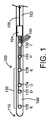
図1は、本開示の装置100の遠位の部分の1例を示す。ここに示されるように、装置100は細長ボディ102を有する。細長ボディ102は、(絶縁された、或いは、絶縁されていない)ワイヤ、カテーテル、ハイポチューブ、および/または、(血管挿入および誘導に関連し、血管挿入および誘導に使用されるために、医療技術において、知られているか、或いは、開発されている)他の細長ボディであり得る。回路モジュール104(ここでは、制御モジュールと称する場合もある)は、図1に示されるように、装置100の一部内に形成され、装置100の一部内に載置され、或いは、装置100の一部上に載置される。(装置100は、ここでは、それらのインピーダンス動作/機能を与えられたインピーダンス装置(複数)と称する場合もある。)導電性ワイヤ(複数)として構成された装置100の実施の形態においては、信号データを細長ボディ102から回路モジュール104まで送ることができるようにするように、そして、幾つかの実施の形態においては、信号データを回路モジュール104から細長ボディ102まで送ることができるようにするように、細長ボディ102は回路モジュール104に接続する。非導電性ワイヤ、カテーテル、ハイポチューブ、または、他のボディとして構成された装置100の実施の形態においては、(例えば、導電性ワイヤのような)導体エレメント106は、細長ボディ102の内側に存在しているか、或いは、細長ボディ102内に形成されているか、或いは、細長ボディ102の外側に配置されるか、または、結合されている。導体エレメント106は、回路モジュール104から、例えば、データ取得および処理システム250(図2に示すような1つの例示的なコンソール)のような回路モジュールより近位の位置まで延びる。他の実施の形態においては、導体エレメント106はコイルとして形成され得る。そして、(細長ボディ102のような)第1の導体および(導体エレメントのような)第2の導体の使用は、装置100のみを用いた双方向の電力/電流の伝送およびデータの伝送を実現可能にするものとなるであろう。
FIG. 1 shows an example of the distal portion of the
図1に示されるように、装置100の遠位部108は、回路モジュール104から装置100の遠位端110まで延びる。様々の実施の形態において、遠位部108はサイジング部(サイズ計測部)120を含む。例えば、サイジング部120は、装置100が管腔臓器内に置かれるときに、断面積、直径、および/または、管腔臓器形状の他の計量を得るために用いられる(ここに詳細に記述される電極122、124、126、128のような)複数の電極を有する。様々の実施の形態において、サイジング部120は、装置100の遠位部108に沿って、例えば、2つの励起電極(図1において「E」としても示される126、128)の間に位置する2つの検出電極(図1において「D」としても示される122、124)のような1または複数の電極を有し得る。例えば、圧力センサ(「P」として示される1つの例示的な「他のセンサ130」)、および/または、温度センサ(「T」として示される他の1つの例示的な「他のセンサ130」))のような、更なるセンサまたは電極は、図1に示されるように、(例えば、遠位部108に、または、装置100の他の部分に)装置100に沿って、或いは、装置100内に配置され得る。例えば、pHセンサ、フロー・センサ、速度センサ、サーミスタ、および/または、他のタイプの化学センサのような、他のタイプのセンサ130が使用されることができ、そして、ここで圧力および/または温度センサ100に関して記述されるように装置100と共に含められ得る。更に、例えば、サイジング用に2つ、または、3つの全長に亘る電極を用いること等により、2つ未満の検出電極122、124、および/または、2つ未満の励起電極126、128がサイジング・データ(サイズ計測データ)を得るために用いられ得る。
As shown in FIG. 1, the
図1に示されるように、複数のワイヤ150が、様々の電極および/またはセンサを個々に回路モジュール104に接続するために用いられ得る。例えば、そして、様々の実施の形態において、1つのワイヤ150が励起電極126を回路モジュール104に接続するために用いられ得、他方で、他の1つのワイヤ150が検出電極122を回路モジュール104に接続するために用いられ得る。少なくとも1つの実施の形態においては、(1つのワイヤ150を使用して)励起電極126を励起電極128に接続するために、更に、(同じワイヤ150、または、直列に接続された他の1つのワイヤ150を使用して)励起電極128を回路モジュール104に接続するために、1つの接続が用いられ、その結果、回路モジュール104から延びる1つのワイヤ150によって回路モジュール104は励起電極126および128に接続される。
同様に、そして、様々の実施の形態においては、(1つのワイヤ150を使用して)検出電極122を検出電極124に接続するために、更に、(同じワイヤ150、または、直列に接続された他の1つのワイヤ150を使用して)検出電極124を回路モジュール104に接続するために、1つの接続が用いられ、その結果、回路モジュール104から延びる1つのワイヤ150によって回路モジュール104は検出電極122および124に接続される。(1つの接続が励起電極126、128、および/または、検出電極122、124を接続するために用いられる)そのような実施の形態においては、これらの電極の組は(2つが短絡して)実効的に単一の電極としての働きをし、例えば、(以下においてより詳細に記述される)パッド200のような、他の1つの電極が戻り電極としての働きをする。ここに記述されるように、(励起用エレメント(励起電極126、128)および電圧記録用エレメント(検出電極122、124)が体表に対して単極性であるので)そのような実施の形態は誘導のために使用されることができた。他方、(電極122、124、126、および、128が各々別々のワイヤ150に接続される)伝統的な4極性の実施の形態がサイジングのために使用されることができた。動作中においては、励起電極126、128は哺乳類の管腔臓器内で電界を励起させることができる。そして、この電界は検出電極122、124によって検出されられ得る。その結果、インピーダンスを用いてコンダクタンスの測定値が得られる。
As shown in FIG. 1, a plurality of
Similarly, and in various embodiments, the detection electrode 122 (using one wire 150) is further connected (
本開示の装置100の少なくとも1つの実施の形態は、回路モジュール104、および、回路モジュールから遠位にある遠位部108を含み、更に、サイジング部120、および、少なくとも1つのセンサ130(例えば、温度センサおよび/または圧力センサ)を含む。
At least one embodiment of the
ここに記述された様々の電極および/またはセンサからデータが得られるように、(回路によって)信号が細長ボディ102または導体エレメント106を通って、或いは、患者の上、または、一般には患者の外部に置かれたパッド200を通って、後方に伝送され得る。その結果、信号データは、電極および/またはセンサから血流を通ってパッド200に、そして、最後に、図2に示されるように、データ取得および処理システム250にまで達することができる。そのような実施の形態においては、パッド200は、例えば、パッド・ワイヤ202によってデータ取得および処理システム250に結合されるであろう。その結果、信号回路全体が完全となる。様々の実施の形態においては、図2に示されるように、装置100はデータ取得および処理システム250に直接結合させることができ、或いは、一例としてカプラー210によってデータ取得および処理システム250に接続され得る。
The signal (by circuit) passes through the
そのような例示的な装置100、または、(例えば、少なくとも装置100、そして、例えば、パッド200、および/または、データ取得および処理システム250のような少なくとも1つの他のアイテムを有する)例示的なシステム300を使用して、サイジングに関するデータ(血管断面積および/または形状)が、圧力または温度に関するような、先に言及した様々の電極および/またはセンサを用いた付加的データと共に、取得され得る。これは、例えば、先に言及した回路を用いて達成することができ、他の場合に必要とされるより少数の構成部品を用いて装置100が構成/製造されるようにすることができる。例えば、装置100の、導体エレメント106が使用されない実施の形態においては、装置100からの信号は、パッド200を用いて検出されることができ、装置100からデータ取得および処理システム250までにおいて何らかの戻りワイヤまたは導体を必要とすることなく、データ取得および処理システム250に送られ得る。回路モジュール104を操作/作動させるために、そして、1または複数の検出電極122、124等によって検出可能な電界を管腔臓器内で発生することができるように電流を励起電極126、128へ供給するために、電力/電流がデータ取得および処理システム250から送られ得る。それから、以下においてより詳細に説明されるように、(サイジング、圧力、温度等のデータのような)データは、パッド200を通って、または、装置100内を戻り方向に通って、データ取得および処理システム250に返され得る。
Such an
本開示の装置100の少なくとも1つの実施の形態においては、サイジングのために使用される電極(例えば、1または複数の検出電極122、124および1つ以上の励起電極126、128)によって、他の如何なる電極またはセンサ無しで、装置100は構成される。例えば、1つの例示的な装置の実施の形態は、回路モジュール104に、個々の電極(または、先に言及した電極の組)を接続するワイヤ150と共に、2つの励起電極126、128の間に置かれる2つの検出電極122、124を有し得る。
In at least one embodiment of the
本開示の装置100の少なくとも1つの実施の形態においては、細長ボディ102および/または(存在するならば)導体エレメント106は、信号源として使用されるのに加えて、地帰路として使用され得る。(信号源としては、例えば、データ取得および処理システム250からの信号および/または電流を提供し、それにより、この電流は、例えば、最終的に1または複数の励起電極126、128を作動させるために用いられる。)そのような1つの例示的な実施の形態においては、前記回路は装置100のみを用いて、例えば、以下の信号によって、完成されることができた。(a)データ取得および処理システム250から細長ボディ102を通って回路モジュール104に到り、最終的に細長ボディ102を通ってデータ取得および処理システム250まで戻る信号、(b)データ取得および処理システム250から細長ボディ102を通って回路モジュール104に到り、最終的に導体エレメント106を通ってデータ取得および処理システム250まで戻る信号、(c)データ取得および処理システム250から導体エレメント106を通って回路モジュール104に到り、最終的に細長ボディ102を通ってデータ取得および処理システム250まで戻る信号、および/または(d)導体エレメント106から細長ボディ102を通って回路モジュール104に到り、最終的に導体エレメント106を通ってデータ取得および処理システム250まで戻る信号。回路モジュール104は、様々の実施の形態において、電力/電流を取得し、励起電極126、128の励起を助け(容易化し)、増幅能力を有し、交流および直流を扱い、及び/又は、パッド200によって検出されるように、細長ボディ102、導体エレメント106、および/または、血流を通って後方に信号を送信することができ、上記の双方向動作/機能は、この回路モジュール104を利用するであろう。様々のセンサ/電極に電力を供給するための導体エレメント106の使用は、例えば、(a)装置100内の単一の導体として、そして、(接地している回路モジュール104に接続され)更に、データ取得および処理システム250に戻る方向に接続されて前記回路を完成するように体表上の電極(例えば、パッド200)を介して接続された励起電極126、128のような)第2の電極としての使用によって扱われることができた。或いは、導体エレメント106の使用は、(b)電源および地気に接続するために前記ワイヤのうちの2つ(2つの導体エレメント106、または、1つの導体エレメント106に電導性の細長ボディ102を加えたもの)を使用することによって扱われることができた。
In at least one embodiment of the
本開示の回路モジュール104は、例えば、0〜3Vの電源によって電力供給され得る。この電源は、(回路モジュール104の内の、及び/又は、励起電極126、128に接続された)コンダクタンス回路に電力を供給し、データ取得および処理システム250にデータ/信号を送信することができた。もし、−3〜0Vの電力供給がなされたならば、(ここで他のセンサ130と称される)圧力および/または温度センサのような他のセンサ/回路に電力供給され、及び/又は、圧力および/または温度データは回路モジュール104から後方へ送られ得る。様々の動作/機能は、例えば、制御線(例えば、導体エレメント106)を用いてどの回路に電力供給し伝送するかをエンコーディングすることによって容易にされることができ、或いは、例えば、機能間でトグルする、電力線(細長ボディ102および/または導体エレメント106)上の、より高い電圧のパルスによって容易にされることができ、或いは、(例えば、3Vと5Vのような)異なる電源電圧を用いることによってさえ容易にされることができた。
更にまた、1つの例示的な導体エレメント106が電力を回路モジュール104へ供給するならば、データ取得および処理システム250からセンサ/電極まで送られている電力に加えて、データは双方向に送られ得る。少なくとも1つの実施の形態においては、直流(DC)電力信号がデータ信号と共に送られ得る。
The
Furthermore, if one
本開示の様々の装置100の実施の形態においては、1または複数の回路モジュール104が単一の装置100内で使用され得る。例えば、そして、装置の幾つかの実施の形態においては、励起電極126、128の励起およびコンダクタンスの測定(検出電極122、124の中の電圧)は、これらを容易にするために、2つ以上の回路モジュール104を必要とする場合があり、或いは、1台の回路モジュール104と他の1つの回路モジュール104内の特徴のサブセットとを使用することを必要とする場合がある。例えば、装置100のボディに組み込まれる独立した導体の必要数を減らす手段として、1つの例示的な回路モジュール104において要求される/必要な機能の全てまたは1つのサブセットが回路モジュール104内に実装されることができた。例えば、検出電極122、124および/または励起電極126、128の1または複数は、付加回路モジュール104(例示的な集積回路またはマイクロマシン組立体)内に集めることができた。
In embodiments of the
少なくとも1つの実施の形態においては、回路モジュール104は、それ自身が(励起電極126、128の1つ、または、検出電極122、124の1つのような)電極として働き、その結果、サイジング部120内の電極の1つの総体的な必要性を減らすであろう。そのような実施の形態は図3に示される。ここでは、サイジング部120内において回路モジュール104が励起電極128の代わりに使用される。他の実施の形態においては、回路モジュール104は、他の1つの電極にとって代わることができた。
In at least one embodiment, the
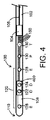
例えば、図4に示されるような、少なくとも1つの他の実施の形態においては、少なくとも1つの装置100の実施の形態は、その上に/その中に検出電極122、124を有するマイクロアセンブリ400を含む。或いは、少なくとも1つの装置100の実施の形態は、マイクロアセンブリ400と少なくとも他の1つの電極とが検出電極122、124として働くように構成される。そのようなマイクロアセンブリ400は、本開示の例示的な装置100の実施の形態で使用されるとき、検出電極122、124の間の長さ(「L」)に関して、より高い精度を実現可能にするものとなるであろう。様々の実施の形態においては、それらの相対的なサイズ/寸法が与えられたときにも、本開示のマイクロアセンブリ400および/または回路モジュール104は柔軟、または、本質的に柔軟である。以下において挙げられる特許および/または特許出願の1または複数において記述されるように、そして、インピーダンス装置100、および、これらのインピーダンス装置100の様々の電極の使用に関して、ここに一般的に記述されるように、これらの装置100の動作中にはコンダクタンス・データが得られる。管腔臓器内の特定の場所において測定された総コンダクタンス(GT)と断面積(CSA)との間を支配する関係は、以下の式によって与えられる。
For example, in at least one other embodiment, as shown in FIG. 4, the embodiment of at least one
GT=(CSA・α)/L+Gp (式1) G T = (CSA · α) / L + Gp ( Equation 1)
ここで、Lは検出電極122、124の間の距離によって決定される定数、αは(血液のような)局所流体の電導率、そして、Gpは並列コンダクタンスである。このことに鑑み、正確なLが重要であり、例えば、特にその上に電極122、124を載置するマイクロアセンブリ400を使用すると、装置100に沿って別々の電極を配置するより正確であることができた。また、そのようなマイクロアセンブリ400は、励起電極126、128の間の様々の場所に載置されることができた。マイクロアセンブリ400の他の様々の実施の形態は、その上に所望の通りに載置された本開示の任意の数の電極/センサを有することができる。
Here, L is a constant determined by the distance between the
以上の記載に従って、本開示の例示的な装置100は、データ取得および処理システム250から回路モジュール104へ供給された電力を使用して、2つの電極/センサに電力を増幅して供給することができた。例えば、回路モジュール104から圧力センサ130への電力は、例えば、同じワイヤ150、または、直列につながれた2つのワイヤ150を通して励起電極128へ供給するために増幅されることができた。2つの電極および/またはセンサに直列に接続された1つのワイヤ150または2つのワイヤ150を介して電源を共有することによって、或いは、電極として1つの構成部品(例えば、回路モジュール104)自体を使用することによって、電極または構成部品の数を減らすために、更なる有効性を得ることもできた。
According to the above description, the
本開示の1つの例示的な装置100の更なる実施の形態は、図5に示される。図5に示されるように、装置100は図1に示される装置100と同様であるが、図5に示される様々の電極/センサに回路モジュール104を接続するワイヤ150はない。そのような装置の実施の形態においては、様々の電極/センサは、回路モジュール104との無線接続によって(無線通信によって)動作し、回路モジュール104は、例えば、導体エレメント106、または、様々の実施の形態においては他の1つの電源を使用して電力供給される。使用の際には、図5に示されるような装置100は、様々の電極/センサが、ここに記述されるように情報/データを得ることができ、そして、回路モジュール104がワイヤレスで前記情報/データを取得し/アクセスすることができるように、動作可能である。図6は、図4および図5と同様の更なる実施の形態を示す。これによれば、その上に電極/センサを有するマイクロアセンブリ400は、また、回路モジュール104との無線通信状態にある。様々の電極/センサが、本開示の例示的なマイクロアセンブリ400および/または回路モジュール104の上に載置されるか、マイクロアセンブリ400および/または回路モジュール104に沿ってエッチングされるか、或いは、マイクロアセンブリ400および/または回路モジュール104内に埋め込まれるかすることができる。前記無線通信は、様々の実施の形態においては、(例えば、電極/センサから回路モジュール104へ、または、その逆のような)1方向であるか、或いは、(例えば、電極/センサと回路モジュール104との間のような双方向であり得る。様々の実施の形態においては、回路モジュール104(または本開示の1つの例示的な装置100の他の部分)は、本開示の様々の電極/センサと通信するように構成された無線通信モジュール600を含む(を有するように構成される)か、回路モジュール104に加えて、この無線通信モジュール600を有する。無線通信モジュール600は、様々の実施の形態においては、導体エレメント106または他の1つの電源を用いて電力供給され得る。図6は、また、装置100の少なくとも部分の周りに置かれるバルーン602を示す。その結果、バルーン602は、例えば、管腔臓器内で、所望のように、膨らませられ、及び/又は、しぼませられ、ここに一般的に記述されるように、コンダクタンスおよび/または他の測定値がインピーダンスを用いてバルーン602内で得られるようにできる。そのような実施の形態は、例えば、様々の程度のインフレーションにおいてバルーン602内で、サイジング・データ(例えば、コンダクタンスの測定を用いた断面積)、圧力データ等を与える。
A further embodiment of one
図7は、本開示の他の1つの例示的なシステム300を示す。図7に示されるように、例示的なシステム300は装置100を含むことができ、装置100は、それ自身が、近位電気ユニット700と、ガイドワイヤ740と、センサ基板760とを含む。ガイドワイヤ740は、その中を貫通する(そして、導体とも称する)少なくとも1つの導体エレメント106と、本開示の例示的な細長ボディ102を含むことができるセンサ基板760とを含む。センサ基板760は、装置100の相対的に遠位の端110に、または、その近くにある。システム300は、例えば、(ここではパッチ電極とも称する)パッド200、および/または、データ取得および処理システム250のような、更なるエレメントを有する。図7に示されるように、近位電気ユニット700はガイドワイヤ740の少なくとも部分に近くにあり、そして、センサ基板760はガイドワイヤ740の少なくとも部分から遠位にある。図8は、他の1つの例示的なシステム300の実施の形態を示す。これによれば、装置100は、近位電気ユニット700とセンサ基板760との間にあるガイドワイヤ740の第1の部分と、センサ基板760の末端にあるガイドワイヤ740の第2の部分とを有し、ガイドワイヤ740の第2の部分はサイジング部120、および/または、1または複数の他のセンサ130を有する。1または複数の他のセンサ130は、例えば、圧力センサ130のように、上記第2の部分の上に載置され、及び/又は、この第2の部分の中に埋め込まれる。一般に、近位電気ユニット700はセンサ基板760から戻る(ここに、より詳細に記述される)データ信号765を処理することができ、近位電気ユニット700の動作を制御することができる。近位電気ユニット700は、例えば、図9に関連して以下において記述されるマイクロプロセッサ900のような、一般に、近位電気ユニット700の中の、および/または、近位電気ユニット700に連結される、1または複数の構成部品を用いる。データ信号765が遠位の部分(センサ基板760)から近位のユニット700まで送られることを理解されるべきである。更に、電力信号710が近位のユニット700からセンサ基板760まで送られると理解されるべきである。データ信号765および電力信号710の両方の伝送は、(ここに、より詳細に記述される)搬送波1000によって達成される。搬送波1000は、ガイドワイヤ106と、遠位ユニット760と、遠位接地768(或いは、ここに、より詳細に記述されるような、センサ基板760の他の部分、または、センサ基板760に接続された部分)と、組織730と、パッド200と、ワイヤ202と、近位のユニット700とからなる完全な電気回路を使用する。
FIG. 7 shows another
本開示の例示的な近位電気ユニット700は少なくとも1つの電源702を有する/含む。電源702は、ここでは、発電機および/または電源と称する場合がある。電源702は、例えば、電源702のバッテリの実施の形態のような、それ自身が正に電力の源である場合もあり、及び/又は、それ自身が、ユニバーサル・シリアル・バス(USB)または(例えば、図9に示すような)他のコネクタ802から、および/または、他の電力ケーブル供給源804(例えば、適切な電源安定化装置を有する伝統的な電源の出力に差し込まれるように構成された従来の電気コード)から電力を受けるものである場合もある。
The exemplary proximal
電源702、USBコネクタ802、および/または、電力ケーブル供給源804からの電力は、直接的に導体106に、および/または、前記電源/コネクタ/供給源のうちの1つ、および/または、近位電気ユニット700の1または複数の他の構成部品を介して間接的に導体106に供給され得る。近位電気ユニット700から導体106へ配給された電力は、導体106を通って、センサ基板760内の、センサ基板760上の、および/または、センサ基板760に埋め込まれた1または複数の構成要素/構成部品まで送られる。図7に示されるように、例えば、電力710は右向きの太線の矢で示されている。好ましい実施の形態においては、電力710は、例えば、200KHz(1秒につき200,000回で交替する)の交流の形で近位のユニット700から遠位ユニット(センサ基板760)まで送られる搬送波)のような、交流電流(AC)またはオシレートする直流電流(DC)として、電源702、USBコネクタ802、および/または、電力ケーブル供給源804から配給される。
Power from the
センサ基板760は、図7および図8に示されるように、比較的小さな、及び/又は、薄い基板を有し得る。これにより、(集積回路とも称される)回路モジュール104は、その基板上に配置され、及び/又は、基板内に埋め込まれる。センサ基板760はそれ自身で本開示のマイクロアセンブリ400である場合があるが、或いは、マイクロアセンブリ400とは別である場合もある。例えば、センサ基板760は回路モジュール104を有するか、或いは、含むことができ、マイクロアセンブリ400は、その上、および/または、その中に、サイジング部120および/または1または複数の他のセンサ130のうちの1または複数を有するか、或いは、含むことができる。図7、図8、および、図9に示されるように、メモリ764(本開示の例示的な記憶媒体)は回路モジュール104、および/または、センサ基板760の他の構成部品に接続され得る。これによって、例えば、メモリ964は、(ここに記述されるように)データ765が近位電気ユニット700に送られ得るまでデータ765を格納することができる。様々の実施の形態において、メモリ764は、上記のように様々のデータを格納することができ、例えば、ここに、より詳細に記述されるようなセンサ基板700の様々の態様を調整し/制御するために、その中に命令および/またはソフトウェアを含むことができる。
The
センサ基板760の構成要素/構成部品は、幾つかの結果を達成するために導体106からの電力710を用いて電力供給され得る。例えば、1つの結果は、コンデンサ762を充電すること、および/または、センサ基板760内またはセンサ基板760上の(図8に示される)遠位電源766へ電力を供給することであり得る。その結果、コンデンサ762および/または遠位電源766からの電力は、センサ基板760内の、または、センサ基板760に接続された1または複数の構成要素を操作するために用いられ得る。他の1つの結果は、サイジング部120および/または他のセンサ130のうちの1または複数(すなわち、動作するための電力を要求しているもの)を作動させることであり得る。例えば、サイジング部120の励起電極122、124を用いて電界を発生すること(または、サイジング部120の他のエレメントを用いて電界を発生すること)であり得る。更に他の1つの結果は、1または複数の導体エレメント106を介して、および/または、以下において記述されるように無線で、サイジング部120および/または他のセンサ130のうちの1または複数から近位電気ユニット700まで後方にデータ信号765を送信することであり得る。図7に示されるように、例えば、データ信号765は、左向きの太線の矢で示されている。他の実施の形態においては、例えば、データ信号765を近位電気ユニット700に送信するために、センサ基板760内の、または、センサ基板760に接続された、有線または無線通信モジュール600(例えば、近位電気ユニット700へデータを送信するように構成された例示的な送信器)を用いる等によって、データは、患者の上に置かれた1または複数のパッドを介して近位電気ユニット700まで後方に伝送され得る。少なくとも1つの実施の形態においては、そして、図8に示されるように、遠位電源766が前述されたことの1つまたは複数を達成するために必要な電力を提供することができるように、遠位電源766がコンデンサ762に接続して使用され得る。そして、様々の実施の形態においては、遠位電源766は、更に、センサ基板760の1または複数の構成部品を操作するために(例えば、電源702によって提供される)交流電流を直流電流に変換することもできる。そのように、そして、上で記述されるように、導体106、コンデンサ762、および/または、遠位電源766からの電力は、前述の結果のうちの1または複数を達成し/容易にするために用いられ得る。様々の実施の形態においては、特に、ガイドワイヤ740からの電力710に一貫性が無く、信頼できない場合には、センサ基板760内の様々の回路に電力を供給するために、コンデンサ762が遠位電源766によって用いられ得る。これによって、コンデンサ762と遠位電源766とがお互いに関連して働いて、一貫して信頼できる電力710をセンサ基板760の部分(複数)に供給する。
The components / components of the
図7または図8に示されるように、上述のようなデータ信号765は、センサ基板760内の、および/または、センサ基板760に接続された、構成部分から生じる。様々の実施の形態においては、(以下において、より詳細に記述される)データ信号765は圧力、温度、および/または、インピーダンス・データを含むことができ、ガイドワイヤ740を介して近位電気ユニット700まで後方に送られる。
一般的な回路は、図7および図8にも示される。その中に示されるように、そして、様々
As shown in FIG. 7 or 8, the data signal 765 as described above arises from components within and / or connected to the
A typical circuit is also shown in FIGS. 7 and 8. As shown in it, and various
の実施の形態について、電力710は、一般に、近位電気ユニット700からガイドワイヤ740を介して、センサ基板760内の、および/または、センサ基板760に接続された、構成部分まで送られる。それから、(様々の実施の形態において、接地768および/または信号770を使用して示されるような)ボディを通って、ボディ上に置かれるパッド200に到って電力回路は完成される。ここで、パッド200からは、例えば、図8に示されるように直接に、または、例えば、図7に示されるように間接的に、近位電気ユニットまで戻る配線がなされる。これは、センサ基板760の1または複数の構成部品、および/または、センサ基板760に接続された1または複数の構成部品、を用いて容易にされる。その結果、例えば、1または複数の電極122、124、126、128、1または複数のセンサ130、および/または、(例えば、ある種のアンテナまたは他の金属エレメントであり得る)接地768、更に/或いは、センサ基板760を構成する、または、センサ基板760に接続された他の1つの金属部品を介して、ある種の金属エレメントは患者の血液、および/または、組織と接触する。ここに一般的に記述されるように、データ信号765は、センサ基板760の構成部品、および/または、センサ基板760に接続された構成部品から、ガイドワイヤ740を通って、または、ガイドワイヤ740に沿って、近位電気ユニット700まで、(ここに、更に詳細に記述されるように)何らかの形で流れることができる。それから、図7および図8に示されるように、データ信号765の回路は、組織730を通りパッド200を介してボディを通って完成される。
In an embodiment of the above,
図7および図8に示されるシステム300の構成部品は、例えば、ここに一般的に記述されるように(例えば、ガイドワイヤのような)例示的な細長ボディ102の一部として導体106が哺乳類の脈管構造の一部を通して挿入され誘導され得るようにセンサ基板760が導体106の一部に、取り付けられ、巻きつけられ、及び/又は、組み込まれるように構成される時の縮尺では描かれてはいない。例えば、細長ボディ102(導体106を有するか、または、含む、全長に亘るガイドワイヤ)は、例えば、0.010インチと0.030インチとの間のような、0.010インチと0.050インチとの間の如何なる直径でもあり得る。例えば、直径0.014インチおよび0.035インチを含むが、これらに限らない。ガイドワイヤ740は様々の金属および高分子の材料を用いて作られることができ、ここに記述されるように1または複数の導体106を使用することができる。センサ基板760、および/または、サイジング部120の様々の構成部品、および/または、センサ130は、ここに一般的に記述されるように、本開示の装置100および/またはシステム300の部分を脈管構造内で誘導してデータを得ることを許容するような全径/サイズであるか、または、それに近い全径/サイズである。
The components of the
前述の内容に鑑み、そして、そのようなシステム300を操作するために必要な回路全体を完成するために、電力が近位電気ユニット700から導体106を通って(例えば、近位の接地704を介して)組織730内に伝送され、システム300の部分を操作してセンサ基板760から近位電気ユニット700まで送られるデータを得る。その結果、近位電気ユニット700はセンサ基板760からフィードバックを(データの形で)得る。
In view of the above, and to complete the entire circuit required to operate such a
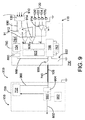
本開示の例示的なシステム300は、例えば、図9に示されるように、更なる構成部品をも有することができる。図9に示されるように、例えば、本開示の1または複数の例示的なシステム300は、近位電気ユニット700、ガイドワイヤ740、および、センサ基板760を含む装置100を有することができる。様々の実施の形態において、ここに記述されるように、近位電気ユニット700は、ハンドルまたは他の構成であり得る、或いは、ハンドルまたは他の構成を含み得る。そして、近位電気ユニット700は、電源702を含み、選択的に、USBまたは他のコネクタ802、および/または、電力ケーブル供給源804(図8に示されるように)を含むことができる。USBまたは他のコネクタ802が、前述のとおり、電源として使用されることができ、及び/又は、(例えば、近位電気ユニット700に接続されたコンピュータ(図示せず)への有線または無線の接続によって)近位電気ユニット700の外へ(例えば、データ信号765のような)データを送信するために使用され得る。マイクロプロセッサ900、または、機能的に等価な構成部品は、近位電気ユニット700内に、または、近位電気ユニット700の一部として、存在し、幾つかの異なる種類の動作のために構成され得る。これらの動作は、例えば、近位電気ユニット700の部分を通る電力710および/またはデータ信号765の流れを制御すること、前述等のような装置100の1または複数の態様を制御するようにマイクロプロセッサ900と通信してオプションのメモリ902(本開示の例示的な記憶媒体)にアクセスすること、等である。図9は、また、ガイドワイヤ740と通信する受信器904を示す。受信器904は、ガイドワイヤ740から1または複数のデータ信号765を受け取るように動作する。これにより、前記1または複数のデータ信号765は装置100のユーザに提供され/示される。そして、前記1または複数のデータ信号765は、これ以降の電力710を制御するため、メモリ902内に前記1または複数のデータ信号765を格納するため、及び/又は、前記1または複数のデータ信号765を、互いと、メモリ902内の他のデータ信号765と、および/または、(例えば、様々のセンサ130および/またはサイジング部120に関連した校正情報/データのような)メモリ902内に格納された他のデータと、比較するために、マイクロプロセッサ900によってアクセスされることができる。例えば、USBまたは他のコネクタ802を介する近位電気ユニット700への接続の一部または全体が動作中に失われても、マイクロプロセッサ900を用いて利用可能なメモリ902内のデータを用いて装置100が依然動作することができるように、データ信号765および/または他のデータはメモリ902内に、そして、近位電気ユニット700の外部に、格納され得る。様々の実施の形態においては、メモリ902は、上述のような様々のデータを格納することができ、近位電気ユニット700の様々の態様を調整して/制御するため、データ取得および処理システム250とインターフェースするため等のための、命令および/またはソフトウェアを含むことができる。
The
ここに一般的に記述されるように、近位電気ユニット700は、上述のように、前記装置100を用いる医療専門家によって把持され得る装置100の相対的なハンドル部分を形成する、及び/又は、そのハンドル部分に位置することができる。一般に、本開示の近位電気ユニット700は(ここに、より詳細に記述され、例えば、図10に示される)搬送波1000を発生することができる、搬送波1000は、ガイドワイヤ740および組織130によって形成された回路を通してセンサ基板760に送られ得る。例示的な搬送波1000はセンサ基板760内の構成要素を操作するために必要な電力710を提供することができ、データ信号765を送信するためにセンサ基板760によって変調され得る。そして、データ信号765は搬送波1000の復調により近位電気ユニット700によって回復される。ここに、より詳細に記述されるように、測定値を得ることが安全であることをセンサ基板760に知らせるために、搬送波1000は中断されることもあり得る。本開示の近位電気ユニット700は、更なる処理および/または表示のために、例えば、図7に示されるように、センサ基板760から得られたデータ信号765をデータ取得および処理システム250まで中継することもできる。この中継は、USB、RS−232、Wi−Fi、ブルートゥース(登録商標)、Zigby、および/または、他の既知の、または、開発された、データを送信する有線および/または無線の手段を用いると容易となり得る。
As commonly described herein, the proximal
様々の実施の形態においては、データ信号765が装置(センサ基板760)の遠位部から近位電気ユニット700までガイドワイヤ740を通して送られるとき、データ信号765は変調される。少なくとも幾つかの実施の形態においては、受信器904は、復調されたデータ信号765がマイクロプロセッサ900に従って取り扱われ得る(受信され、処理される等)ように、前記データ信号765を復調するように構成される。
In various embodiments, the data signal 765 is modulated when the data signal 765 is sent from the distal portion of the device (sensor substrate 760) to the proximal
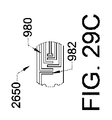
装置100(センサ基板760を含む)の遠位の部分は、図9に示される構成部品/特徴の一部もしくは全部を有することができる。例えば、そして、その中に示されるように、本開示の例示的なセンサ基板760は、(ここでは集積回路とも称する)回路モジュール104、有線または無線通信モジュール600(データ信号765が近位電気ユニット700に提供され得るようにセンサ基板760からガイドワイヤ740までデータ信号765を送信するように構成された例示的な送信器)、圧力センサ(例示的なセンサ130)、および、(例えば、電極122、124、126、128を有する)サイジング部120を有し得る。様々のワイヤまたはトレース980が近位電気ユニット700および/またはセンサ基板760内に存在することができ、ここに一般的に記述されるような動作のために多くの構成部品をお互いに接続するために用いられる。例示的なワイヤまたはトレース980が図9に示される。
The distal portion of device 100 (including the sensor substrate 760) can have some or all of the components / features shown in FIG. For example, and as shown therein, the
本開示の例示的な圧力センサ(センサ130)は、それにかかる圧力の変化に応じて曲がるダイアフラム910を有し得る。例えば、図9の中の3本の左向きの矢は、センサ130のダイアフラム910に対する力を示す。これにより、例えば、ダイアフラム910の外の部分が延ばされ、ダイアフラム910の内側は圧縮される。センサ910に、直接、または、1または複数のワイヤまたはトレース980によって接続される、例示的なブリッジ912は、ダイアフラム910の内側と外側との間の非常に小さな差を測定することができ、これにより、センサ130からの非常に小さい信号を検出できる。また、例示的なブリッジ912は、それに接続される1または複数の増幅器914を介して、1または複数のデータ信号765を、センサ130からマルチプレクサ920へ、及び/又は、直接、送信器(有線または無線通信モジュール600)へ、分配する。それから、送信器は、ガイドワイヤ740によって、および/または、(無線送信器が使用されるときは)無線で(例えば、1または複数の無線信号、無線周波数信号/波、ブルートゥース(登録商標)等を用いて)データ信号765を近位電気ユニット700へ送信することができる。増幅器914は、図9に示されるように、データ信号765全体の強度を増幅するように、ブリッジ912からのデータ信号765を増幅することができる。図9に示されるように、例えば、ブリッジ912は、圧力センサ(センサ130)から2つのデータを実際に受け取ることができる。2つのデータのうちの1つは、圧力の1つの変化のみに関係するダイアフラム910の内側の変化と外側の変化との間の差であり、他の1つは、これらの変化の和であり、(例えば、圧力センサ130が温度変化を補償することができるときは)この和は、温度成分をも利用する。上記の点に鑑み、増幅器914は、両方の種類のデータ信号765(図9にて「P」で示した圧力、および、図9にて「T」で示される温度)を増幅することができる。同様に、マルチプレクサ920に到達する前にそれらの全体強度を増やすために、増幅器は、サイジング部120からの(図9にて「Z」として示された)インピーダンスのデータ信号765を、図9に示されるように、増幅することができる。
An exemplary pressure sensor (sensor 130) of the present disclosure may have a
本開示の(1または複数の)例示的な圧力センサ130は、医療器具100の遠位先端110の近くに置かれることができ、血液の圧力を測定するように構成されている。多くの実施の形態が可能であるが、少なくとも1つの実施の形態は、可撓性の基板(上記のダイアフラム910)の互いに対向する側に取り付けられる1対の歪みゲージから成る。可撓性の基板の一方の側にかかる力が反対側に対して相対的に変化すると、可撓性の基板は曲がり、その曲率を変化させる。前記2つの歪みゲージが差動対として構成されるとき、完全または半ホイートストン・ブリッジから測定される信号は圧力センサ130にかかる法線力に比例している。しかし、歪みゲージが直列の抵抗(複数)として構成されるとき、上に一般的に記述したように、生成される信号は血液の温度と比例している。
The
図9に示されるマルチプレクサ920は、例えば、(1または複数)センサ130、および/または、サイジング部120のような様々の入力からデータ信号765を得ることができ、一度に1つのデータ信号765を、要望されるように、転送および/または処理することができる。例えば、図示されるように、マルチプレクサ920は、サイジング部120からのサイジング(インピーダンス)データ信号765と同様に、(圧力センサとして構成された)センサ130から圧力および温度のデータ信号765を得ることができる。マルチプレクサ920は、前記データ信号765を受け取った後に、一度に1つずつそれらを分配することができる。(例えば、サイジング部120からの、または、サイジング部120に関するデータ信号765を最初に分配し、それから、センサ130からの、または、センサ130に関するデータ信号765を分配する。アナログ/デジタル変換器922は、図9に示されるように、(相互通信で)マルチプレクサ920に接続され得(マルチプレクサ920と通信し得)、サイジング部120および/またはセンサ130からのアナログのデータ信号765をデジタル信号765に変換するように動作することができる。それから、デジタル信号765は、(例えば、集積回路および/またはマイクロプロセッサのような)回路モジュール104へ転送され、有線または無線通信モジュール600(本開示の例示的な送信器)によって近位電気ユニット700まで後方に送信される。様々の実施の形態においては、有線または無線通信モジュール600は、例えば、コイル、電極122、124、126、128のうちの1つ、或いは、別の電極のように、それ自身で、電極である(または、電極として構成される)。その結果、データ信号765は近位電気ユニット700へ正しく送られ得る。
The
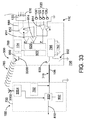
例示的なセンサ基板760は、動作中に、1または複数のスイッチを利用し得る。例えば、第1のスイッチ930は、ガイドワイヤ740、有線または無線通信モジュール600、および、遠位電源766を(電力710、および/または、データ信号765によって)電気的に接続するために用いられ得る。図9に示されるように、第2のスイッチ932は、(電力710および/またはデータ信号765によって)遠位電源766を組織730と電気的に接続するために用いられ得る。図13は遠位ユニット(センサ基板760)によって決定されるイベント発生1300を示す。遠位ユニットは近位電気ユニット700のスレーブとして動作する。簡潔に言えば、そして、図13に示されるように、イベント発生1300は開始ステップ1302に始まる。そして、(図9に示されるようなスイッチS1(第1のスイッチ930)およびS2(第2のスイッチ932)の閉鎖によって達成される)分離オフ状態1304にあることによって、センサ基板760は、最初は、ガイドワイヤ740および組織130に効果的に接続している。その時、搬送波1000が中断されるときに(センサ基板760内の)遠位の回路を管理するために必要な電力を提供するために、ここに記述されるコンデンサ762(複数)は充電される。遠位ユニット(センサ基板760)は電力を(「電力はONか」ステップ1306によって)をモニタし続ける、そして、電力がOFFであるとき、すなわち、搬送波1000が近位電気ユニット700によって中断されるとき、センサ基板760は測定モード(測定ステップ1310)に入る。初めに、図9に分離オン状態1308によって示されるように、遠位先端電子回路(センサ基板760内の構成部品)は組織130から分離される。これは、図9に示されるように、スイッチS1およびS2(それぞれ第1のスイッチ930と第2のスイッチ932)を開くことによって達成される。その後、インピーダンス、圧力、および/または、温度の測定が行われ得、遠位先端電子回路の電気的絶縁は(分離オフ状態1312によって)終了される。この時点で、結果として生じる測定値(データ信号765)を(データ伝送ステップ1318によって)搬送波1000の変調によって近位電気ユニット700に送り返そうとする前に、(センサ基板760の)遠位先端回路は(近位電気ユニット700の)近位の回路による搬送波の回復を待つ。一旦、(「電力はONか」ステップ1314によって)電力がONに戻ると、短時間の遅延(遅延状態1316)がデータ伝送ステップ1318に先行することができる。変調スキームは、利用可能な多くのもの(例えば、振幅変調、パルス位置変調、パルス幅変調、その他)から選ばれ得る。同様に、データ(データ信号765)の符号化は、利用可能な技術の大規模な選択肢から選ぶことによって為され得る。例えば、振幅変調およびマンチェスター符号化はゼロオフセットで信号を生成するので、振幅変調およびマンチェスター符号化が好まれ得る。このことは、組織130を通して送られるデータ信号765にとって、副作用および意図しない刺激を防止するために重要である。スイッチ930、932の開閉については、ここに、より詳細に議論される。
An
様々の更なるワイヤまたはトレース980が近位電気ユニット700および/またはセンサ基板760内に存在することができる。そして、ここに一般的に記述されるような動作のために多くの構成部品をお互いに接続するために用いられる。例示的なワイヤまたはトレース980が図9に示される。
Various additional wires or traces 980 can be present within the proximal
図10に示される例示的な搬送波タイミング図を考慮して、本開示の例示的な装置100および/またはシステム300の新規な動作が記述され得る。その中に示されるように、近位電気ユニットからの電力信号全体と共に、単一の搬送波1000が、装置100および/またはシステム300の様々の態様の動作を制御するために使用される。例えば、そして、図10に示されるように、例示的な搬送波1000は、(それによって、装置100を用いる測定値が哺乳類の脈管構造の中で得られる)測定部分1002と、(それによって、導体106からの電力710を用いてセンサ基板760内の構成要素が充電される、言い換えれば、近位電気ユニット700によって電力710がONに戻される)充電部分1004とを有する。測定部分1002においては、例えば、センサ基板760の構成部品は、ガイドワイヤ740からセンサ基板760に電力710が流れ込んでいないことを確認する。このことは、前記電力710の流れによる電気的干渉無しにセンサ130および/またはサイジング部120を使用して1または複数の測定値を得るためのトリガとしての働きをすることができる。本開示の搬送波1000もまた、(それによって、装置100を用いて得られるデータは近位電気ユニット700へ戻される)データ伝送部分1006と、(そこではデータは得られず、送られない)スタンバイ部分1008とを含む。そして、スタンバイ部分1008が、装置100および/またはシステム300が更なるデータを得るためのトリガとしての働きをする。測定部分1002の間に、電力710は近位電気ユニット700からセンサ基板760に提供されない。測定部分1002は、センサ基板760の1または複数の構成部品が圧力、温度、および/または、インピーダンスの1または複数の測定値を得るためのトリガとしての働きをすることができる。例示的なデータ伝送部分1006の間に、センサ基板760の構成部品は、次第に消耗する電流/電力の全体量を変え得る。そして、近位電気ユニット700は、この電力消耗をモニタすることができる。センサ基板760は、(例えば、比較的少ない電力、または、比較的多くの電力を二進数の0または1と考えて)次第に消耗する電力の量を意図的に変えることができる。様々の実施の形態においては、スタンバイ部分1008の間に、電力710はコンデンサ762を充電するために用いられ得る。
In light of the exemplary carrier timing diagram shown in FIG. 10, a novel operation of the
一般に、そして、ここに記述されるように、本開示の例示的な装置100は、同じガイドワイヤ740を通って電力710および複数のデータ信号765を送信するように動作可能で、及び/又は、そのように構成される。様々の装置100のように、本出願のサイジング部120および/またはセンサ130は電気的に接続し、電流(電力710)を送り、様々の測定値(結果としてデータ信号765になる)を、同時に、または、互いに非常に近い時間に取得する。単一のコア(信号導体エレメント106または導体)を用いて、電力710およびデータ信号765は、体(組織130)によって完成される電力およびデータの回路全体によって、同じコアを通して送られ得る。このことに鑑み、様々の実施の形態において、本開示の装置100は、データ信号765および電力710の複数のチャネルを使用することとして考えられ得る。
In general, and as described herein, the
図11は、本開示の例示的な近位電気ユニット700からの例示的なイベント発生1100のステップを示す。その中に示されるように、例示的な装置100は(開始ステップ1102を使用して)動作を開始することができ、(パワーオフ・ステップ1104を使用して)電力伝送は止められ得る。これによって、(組織固有のキャパシタンスのための時間を少なくして、より完全な測定値を得られるようにするために含まれる)パワーオフ・ステップ1104または遅延ステップ1106において、装置100および/またはシステム300の部分(複数)を用いて、例えば、インピーダンス、圧力、および/または、温度のような測定値が得られ得る。例えば、データ取得の間の、そのような伝送からの潜在的な負帰還を最小にして、より完全な(したがって、より正確な)データ取得プロセスを実現可能にするように、前記の測定値は、導体106を通してセンサ基板760に電力が伝送されていないときに得られるであろう。それから、例えば、センサ基板760内の無線通信モジュール600が、例えば、近位電気ユニット700にデータ信号765を送信することができるように、センサ基板706へ電力を供給するために、(パワーオン・ステップ1108を用いて)電力供給がオンにされ得る。もう1つの遅延ステップ1110がパワーオン・ステップ1108に続く。その結果、パワーオン・ステップ1108により、組織キャパシタンスは減じられることができ、データ受信ステップ1112の中で装置100および/またはシステム300を用いて取得されたデータの、より完全な伝送を実現可能とすることができる。更なる遅延ステップ1114がデータ受信ステップ1112に続くことができる。図11に示されるイベント発生1100における最後のステップ、データ伝送ステップ1116において、近位電気ユニット700および/またはデータ取得および処理システム250にデータ信号765を送ることになる。データ伝送ステップ1116において一旦データが送られたならば、図示されるようにプロセスは繰り返すことができる。遅延ステップ1106、1110、および、1114はオプションであるが、装置100および/またはシステム300の最も完全な動作を実現可能にするために様々の実施の形態において推奨される。
FIG. 11 shows the steps of an exemplary event occurrence 1100 from an exemplary proximal
ここに記述されるように、単一の導体(単一の導体エレメント106)を用いる装置100および/またはシステム300の実施の形態は、哺乳類の組織130を使用して電力および/またはデータの回路全体を完成することができる。前記装置100は好適な柔軟性および/または操縦性を有する。もし、複数のコア(導体エレメント106)が使用されるならば、ここに記述されるように小さいサイズのガイドワイヤ740が幾らか傷つけられるであろう。
As described herein, embodiments of
しかし、本開示は、例えば、図12に示されるような、2つ以上のコア(導体/導体エレメント106)を有する装置100の開示も含む。その結果、回路全体が装置100内で完成され得る。例えば、そして、図12に示されるように、装置100は、近位電気ユニット700と、2つの導体エレメント106を有するガイドワイヤ740と、遠位のセンサ基板760を含むことができる。各々が、ここに記述される様々の特徴および/または構成要素を有する。(図12に示されないが、他の図に示される)電力710およびデータ信号765は、図12に示されるように、近位電気ユニット700、第1の導体エレメント106、センサ基板760、および、第2の導体エレメント106によって作られたループを通して送信され得る。
However, the present disclosure also includes disclosure of a
(センサ基板760内の)遠位の回路によって対処されなければならない少なくとも1つの問題は、例えば、電力回路と測定されているインピーダンスとの間の共通の電気経路の存在である。4極(4極性の)インピーダンス技術(ここに一般的に記述されるように、2つの励起電極126、128は、2つの励起電極126、128の内側に置かれた2つの検出電極122、124を用いて検出可能な電界1400を発生するために用いられる)を用いる電気インピーダンス測定の原理が図14および図15に図示される。図16および図17内で確認されるように、そこからインピーダンスが測定される組織と同じ組織を通して電力が供給されるとき、残りのシャント経路は測定通路内に残り、インピーダンス測定の結果を不正確にする。この問題を解決するために、(近位電気ユニット700内の)近位の回路が搬送波1000を止めるサイクル部分の間だけ、測定が行われ得る。その時、(センサ基板760内の)遠位の回路は、図9に示されるように第1のスイッチ930および第2のスイッチ932を開くことによって、分離をオンにする。本開示の様々の実施の形態においては、電極122、124、126、128は装置100の遠位の部分110の周りの環(複数)として作成される。これらの電極は通常1mm幅の帯で、白金イリジウム合金から作られる。しかし、異なるサイジングと異なる材質も本開示内に含まれる。個々の電極122、124、126、128の間の間隔は、0.5〜10mmの範囲にある。
At least one problem that must be addressed by the distal circuit (in the sensor board 760) is, for example, the existence of a common electrical path between the power circuit and the impedance being measured. 4-pole (4-polarity) impedance technology (as commonly described herein, the two
図18は本開示の例示的な装置100の遠位の部分(センサ基板760)を示す。この遠位の部分は、2つのコンデンサ762、4つの電極122、124、126、128、圧力センサ(例示的なセンサ130)、および、集積回路(回路モジュール104)を有する。これらは、様々のワイヤまたはトレース980を用いて図示されるように接続され、ここに一般的に記述されるような動作のために構成される。図19は、本開示の様々の装置100を用いた際の、例示的な電力710およびデータ信号765の流れ方向を示す。それによれば、例えば、近位電気ユニット700からガイドワイヤ740を通ってセンサ基板760へ、(前述の1または複数のメカニズムまたは方法によって、例えば、一般的な回路/ループを延ばすような、センサ基板760の金属部品、或いは、センサ基板760に接続された金属部品の接触によって)パッド200へ、そして、逆に、パッド・ワイヤ202および/またはカプラー210を経て近位電気ユニット700へと、電力710は流れる。また、例えば、データ信号765は、センサ基板760からガイドワイヤ740を通って近位電気ユニット700へ、そして、逆に、図示のようにループ/回路を完成するべくセンサ基板760へと流れる。図7、図8および図19に示されるように、例えば、電力710は一般に一方向に動くものとして、そして、データ信号765は一般に他の方向に動くものとして示されている。(要望に従って、交流電流(AC)またはパルス直流電流(DC)による)電子が回路に沿って両方の方向に動くが、例えば、電源702からセンサ基板760の回路モジュール104までの電力710の流れ全体、そして、例えば、回路モジュール104から近位電気ユニット700へ戻るデータ信号765の流れ全体を示すために、図7、図8および図19に示される矢が含まれている。電力710およびデータ信号765の流れに関して、2つの導体を用いて回路全体は完成される。2つの導体の少なくとも1つはガイドワイヤ740の第1の導体エレメント106であり、そして、他は、例えば、ここに記述されるように、体を通ってパッド202およびパッド・ワイヤ202へ戻ることで完成される。
FIG. 18 shows the distal portion (sensor substrate 760) of the
ここに一般的に記述されるように、本開示の様々の装置100およびシステム300は、例えば、狭窄した領域の位置を特定するため、更に、例えば、様々の治療装置の事前選択を潜在的に支援するためにインピーダンスを用いて断面積の測定値を得るため等、哺乳類の脈管構造の内側で測定値を得るために有用である。インピーダンス、血圧、および/または、温度は、本開示の様々の経血管的装置100および/またはシステム300を使用して得ることができる。
As commonly described herein, the
ここに一般的に記述されるように、本開示の様々の装置100は、例えば、ここに記述された電極122、124、126、および/または、128のような、様々の電極を有するサイジング部120を含むことができる。ここで、様々の電極は、それらの4つの電極、更なる電極、および、より少数の電極を含む。装置100の実施の形態は、サイジング部120、(例えば、サーミスタまたは熱電対のような)温度測定値を得るように構成されたセンサ130、および/または、(例えば、圧力センサのような)圧力測定値を得るように構成されたセンサ130のうちの1または複数を含むことができる。適用可能な場合には、医療技術において使用される他のセンサ130が様々の装置100および/またはシステム300の実施の形態に組込まれ得る。
As commonly described herein, the
2つのカスタム回路が本開示の例示的な実施の形態を試験するために作られた。回路の1つは、近位の回路と称され、搬送波の発生、電力の伝送、遠位の回路からのデータの受信、および、外部コンピュータとの通信を含む、図7に示されるような、近位電気ユニット700の機能を実行する。この例では近位電気ユニット700の動作は、「プロセシング(Processing)」言語で書かれたプログラムを実行するアルドゥイーノ・ウノ・マイクロコントローラ・ボードによって制御される。この同じボードは、USB接続802を用いる外部コンピュータと通信した。電力は、9ボルトの一次電池から得られた。バッテリからの全体的な電流は、約80ミリアンペアであった。
Two custom circuits have been created to test the exemplary embodiments of the present disclosure. One of the circuits, referred to as the proximal circuit, includes the generation of carriers, the transmission of power, the reception of data from the distal circuits, and the communication with external computers, as shown in FIG. Performs the function of the proximal
第2の回路は、遠位の回路と称され、例えば、搬送波からの電力回復、マンチェスター符号化を用いる搬送波の振幅変調(AM)によるデータ伝送、圧力センサ、温度センサ(両者は例示的なセンサ130)、および、4極の/4極性のインピーダンス・センサ(例示的なサイジング部120)を含むオンボード・センサを用いたデータ取得を含む、図7に示されるような、センサ基板760内の、または、センサ基板760上の構成要素の機能を実行する。使用された圧力は、また、温度センサとして用いられた差動歪みゲージ・センサである。遠位の回路の動作は、C++言語で記述されたプログラムを実行するPIC 16F690マイクロコントローラによって制御された。
The second circuit is referred to as the distal circuit, for example, power recovery from the carrier wave, data transmission by carrier wave amplitude modulation (AM) using Manchester coding, pressure sensor, temperature sensor (both are exemplary sensors). 130), and in the
使用される搬送波は、近位の回路で発生された200のKHzの方形波であった。
以下に記述され、更に、図20に図示されるが、データ伝送は、長さ14ビットのデータ・パッケージを使用して、9,600ボー(ビット/秒)で行われた:
ビット01:スタート・ビット(常に「1」)
ビット 02および03:
チャネル番号(00:予備、01:インピーダンス、02:圧力、03:温度)
ビット 04 ― 13:10ビットのデータ
ビット 14:偶パリティ・ビット
The carrier used was a 200 KHz square wave generated in a proximal circuit.
As described below and further illustrated in FIG. 20, data transmission was performed at 9,600 baud (bits per second) using a 14-bit long data package:
Bit 01: Start bit (always "1")
Channel number (00: reserve, 01: impedance, 02: pressure, 03: temperature)
Bits 04-13: 10-bit data bits 14: Even parity bits
マンチェスター符号の使用は、以下の論理レベル・シーケンスを用いてデータ伝送が為されるべきことを要求する。すなわち、図21に図示されるような、低レベルと、後に続く高レベルとからなるデータ値「1」の伝送のための論理レベル・シーケンス、および、高レベルと、後に続く低レベルとからなるデータ値「0」の伝送のための論理レベル・シーケンスである。 The use of Manchester codes requires that data transmission be made using the following logic level sequences. That is, it consists of a logical level sequence for transmission of data value "1" consisting of a low level followed by a high level, as illustrated in FIG. 21, and a high level followed by a low level. A logical level sequence for transmission of data value "0".
搬送波の電流強度は、常に1ミリアンペア未満に保たれた。
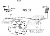
波を搬送するために必要な電気回路は、図22に示されるように単線および組織を用いて形成された。組織への接続は、1対のパッチ電極を用いて為された。
The current strength of the carrier was always kept below 1mA.
The electrical circuits required to carry the waves were formed using single wires and tissue as shown in FIG. The connection to the tissue was made using a pair of patch electrodes.
短時間の生体内研究の間、雄ウサギが、処置の間を通して吸入ガスを用いて麻酔下に維持された。頸静脈および大腿静脈への脈管アクセスは、通常の切開によって、そして、両方の部位に導入器を配置することによって取得される。0.035インチLumenRECONガイドワイヤは頸静脈エントリ・ポイントから静脈に入れられ、そして、上大静脈内に進められた。静脈系に導入された放射線不透過性染料は、ガイドワイヤが4つの異なる位置に移動される間に様々の位置における静脈の直径を推定するために後で用いられる血管の静脈造影像を捕えるために用いられた。最後に、番号2および3を付けられたインピーダンス電極(例示的なサイジング部120の例示的な検出電極122、124)の中心から19mmの距離から室温生理食塩水(0.9%NaCl)を放出するために4フレンチMerit KA2カテーテルが用いられた。
During a brief in vivo study, male rabbits were maintained under anesthesia with inhaled gas throughout the procedure. Vascular access to the jugular and femoral veins is obtained by routine incision and by placing introducers at both sites. A 0.035 inch Lumen RECON guidewire was placed into the vein from the jugular vein entry point and advanced into the superior vena cava. The radiopaque dye introduced into the venous system captures venous images of blood vessels that will be used later to estimate the diameter of veins at various positions while the guidewire is being moved to four different positions. Was used for. Finally, room temperature saline (0.9% NaCl) is released from a distance of 19 mm from the center of the impedance electrodes numbered 2 and 3 (
研究の間に以下の観察が為された。
1.近位および遠位の回路が単線+動物組織経路を用いて接続されたとき、近位の回路に存在する「戻り信号受信表示」に示されるように、遠位の回路が電力供給された。
2.遠位の回路に備えられたマイクロプロセッサ(例示的な回路モジュール104)が固定のデータ値を送信するようにプログラムされた場合、それらの値は近位の回路によって確実に受け取られ、USBポートを通ってコンピュータに送信され、組織を通した頼できるデータ伝送が達成され得ることがコンピュータ・スクリーン上に表示された。
3.遠位の回路に備えられたマイクロプロセッサが、トランスジューサからデータを送るようにプログラムされた場合、圧力センサのデータが受け取られる。圧力センサに手の力が加えられると、圧力データの変化が観測され、圧力センサ・インターフェースが機能することを示した。
4.図23に示されるようにガイドワイヤがウサギの静脈内で異なる場所に置かれるとき、遠位の回路上にある4極のインピーダンス・センサ(例示的なサイジング部120)を用いて生体内電気インピーダンスを測定することができた。
研究の間、以下の表1に示されるように、4つの異なる位置が試みられた。
The following observations were made during the study:
1. 1. When the proximal and distal circuits were connected using a single wire + animal tissue pathway, the distal circuits were powered as shown in the "return signal reception display" present in the proximal circuits.
2. 2. If a microprocessor in the distal circuit (exemplary circuit module 104) is programmed to send fixed data values, those values will be reliably received by the proximal circuit and the USB port. It was displayed on the computer screen that it was sent to the computer through and reliable data transmission through the organization could be achieved.
3. 3. If the microprocessor in the distal circuit is programmed to send data from the transducer, the data from the pressure sensor will be received. When hand force was applied to the pressure sensor, changes in pressure data were observed, demonstrating that the pressure sensor interface worked.
4. In vivo electrical impedance using a 4-pole impedance sensor (exemplary sizing section 120) on the distal circuit when the guidewires are placed in different locations within the rabbit vein as shown in FIG. Was able to be measured.
During the study, four different positions were attempted, as shown in Table 1 below.

表1に表形式で示され、そして、図24に図の形式で示されるデータは、コンダクタンスと血管の断面積との間の予測された関係を示す。 The data shown in tabular form in Table 1 and in the form shown in FIG. 24 show the predicted relationship between conductance and the cross-sectional area of the vessel.
室温の生理食塩水(0.9%NaCl)のボーラス量が、血管内の、ガイドワイヤの電極2および3の中心から19mm離れている位置に4フレンチMerit KA2カテーテルを用いて射出されたとき、図25に示されるような電圧の過渡応答が観察された。
生理食塩水は血液と比較してより高い導電性を有するので、カテーテルの遠位の部分を食塩水が通過する間、予想通り、電極2と3との間で観察される電圧降下は少なくなっていた。
When a bolus amount of room temperature saline (0.9% NaCl) was injected using a 4 French Merit KA2 catheter 19 mm away from the center of the guide wire electrodes 2 and 3 in the blood vessel. A transient response of the voltage as shown in FIG. 25 was observed.
Saline has a higher conductivity compared to blood, so, as expected, the voltage drop observed between electrodes 2 and 3 is less while the saline passes through the distal portion of the catheter. Was there.
本開示の例示的な装置100の実施の形態の部分(複数)は、図26の分解部品図に示される。その中に示されるように、導体エレメント(導体106)は少なくとも3つの部分、すなわち、近位セグメント2600、遠位セグメント2602、および、内側セグメント2604を有する。ここで、近位セグメント2600および遠位セグメント2602は、各々、内側セグメント2604の対向する端部に結合するように構成される。図26に示されるように、内側セグメント2604は、その上に対応するラップ2650を受けるように構成される。ここで、ラップ2650は内側セグメント2604の殆ど、または、全ての周りに巻きつけられるように構成される。近位セグメント2600は、内側セグメント2604に接続され/結合され得る。そして、遠位セグメント2602もまた、様々の接続および/または手段を用いて、例えば、接着剤、(半田、および/または、更なる金属の使用のような)溶接、(溶断プラスチックのような)融解物、撚り、摩擦等のうちの1または複数を使用して、内側セグメント2604に接続され/結合され得る。本開示の装置100の少なくとも1つの実施の形態においては、そして、図26に示されるように、近位セグメント2600および遠位セグメント2602が、各々、内側セグメント2604に接続され/結合されるであろうそれらの端において、タブ2606を有し、内側セグメント2604は、内側セグメント2604を接続するためにタブ2606を受け入れるために、各端部において、その中に形成されたポケット2608を有する。
A portion (s) of embodiments of the
図26に示されるように、コンポーネント・ハウジング2675は、例えば、圧力センサ(例示的なセンサ130)、(ここでは集積回路またはASICとも称する)回路モジュール104、および、コンデンサ762のような、本開示の例示的な装置100の様々の構成部品を受け入れるように構成される。図26に示されるように、転送回路2680は、例えば、ラップ2650および/または内側セグメント2604の上、または、内側に含まれるような、装置100の他の部分の上に形成された他のワイヤまたはトレース980に接触するか、または、係合するように構成された、様々のワイヤまたはトレース980を有することができる。例えば、様々のワイヤまたはトレース980が、コンポーネント・ハウジング2675の中で1または複数の構成部品を接続するために用いられることができ、及び/又は、コンポーネント・ハウジング2675の中の構成部品が装置100の他の部分と電気的に通信することを許容するように転送回路2680の接続を提供するために用いられることができる。ここで、装置100の他の部分は、例えば、他のワイヤまたはトレース980、サイジング部120の構成部品、圧力センサ(例示的なセンサ130)、導体エレメント(または導体)104、および、(例えば、近位セグメント2600および/または遠位セグメント2602のような)装置100の様々の部品のようなものである。
As shown in FIG. 26, the
図26および図27に示す例示的な装置100の実施の形態の全体の組立ての間に、例えば、圧力センサ(センサ130)、回路モジュール104、および、コンデンサ762のような、コンポーネント・ハウジング2675内に置かれることを意図される構成部品は、コンポーネント・ハウジング2675内に配置される。コンポーネント・ハウジングの1または複数の開口2676は、例えば、血液が圧力センサ(センサ130)に接触することを許容して、装置100の使用中に圧力を読み取ることができるようにするように、コンポーネント・ハウジング2675内に形成される。転送回路2680は、装置100の他のワイヤまたはトレース980または構成部品と接触するように構成された、コンポーネント・ハウジング2675の他のワイヤまたはトレース980と接触することができるか、或いは、図30Aおよび図30Cに示されるように、転送回路2680を露出するようにコンポーネント・ハウジング2675内に形成された転送回路の開口2678を通して露出されることができる。
During the entire assembly of embodiments of the
コンポーネント・ハウジング2675は、その中の構成部品と共に、内側セグメント2604内に配置されることができる、その結果、内側セグメント内に形成される、内側セグメントの1または複数の開口2610は、コンポーネント・ハウジング2675内に形成されたコンポーネント・ハウジングの1または複数の開口と一致する/揃う。ラップ2650は内側セグメント2604に巻きつけることができる、そして、近位セグメント2600および遠位セグメント2602は、図26に示されるように装置100の制作を完了するために、内側セグメント2604に接続され得る。ラップ開口2655は、図26に示されるように、内側セグメントの1または複数の開口2610およびコンポーネント・ハウジングの1または複数の開口2676と一致する/揃うことができる。その中に示されるように、ラップ2650が内側セグメント2604の周りに配置されるとき、(例えば、(図26および/または図28Cに示される)電極122、124、126、128、遠位導体パッド2620、(図29Dおよび29Eに示されるような)近位導体パッド2700、および/または、様々のワイヤまたはトレース980のような)装置の様々の構成部品は、ワイヤまたはトレース980、遠位導体接点2612、1または複数の電極接点2614、および/または、近位導体接点2616のような、内側セグメント2604の様々の部分に接触することができる。
The
図27は、図27に示される装置100の一部分の斜視図を示す。この一部分は、内側セグメント2604の周りにラップ2650を配置するためではあるが、一般的に組立られる部分である。図27に示されるように、圧力センサ(センサ130)、回路モジュール140、および、コンデンサ762が装置100の内側に配置される。図27に示されているのは、これらの構成部品を見るための部分破断図である。図27はまた、哺乳類の脈管構造の内側で、装置100を通って送られるように構成されたカテーテル2750の遠位の部分を示す。それによって、ここに一般的に記述されるように、例えば、食塩水のような、オプションの流体がカテーテル2750を通して配給されることができ、この流体のボーラスが1または複数のサイジング部120および/またはセンサ130を越えて通ることができ、それによって検出され得る。
FIG. 27 shows a perspective view of a part of the
図28Aは、図28Cに断面B−Bに沿って示されるような、本開示の例示的な装置100の一部の断面図を示す。その中に示されるように、その上にラップ2650が配置された、装置100は、圧力センサ(センサ130)および転送回路2680を含む。ここで、圧力センサは、1または複数のコンポーネント・ハウジング開口2676をその中に形成されたコンポーネント・ハウジング2675内にある。図28Bは、図28Dに示される断面A−Bに沿った断面図を示す。ここでは、様々の構成部品は、その上にラップ2650を配置された装置100の内側に示される。図28Cおよび図28Dは、その上にラップ2650が配置された本開示の例示的な装置100の遠位の部分の、互いから90°回転した側面図である。ここで、電極122、124、126、128および遠位導体パッド2620がその上に示される。
FIG. 28A shows a cross-sectional view of a portion of the
図29Aは、その上にラップ2650が配置された本開示の例示的な装置100の一部の斜視図である。ここで、電極122、124、126、128、遠位導体パッド2620、および、近位導体パッド2700がその上に示される。そのような図は、装置100の最も遠位の部分および最も近位の部分を示さない。図29Bは、ラップ開口2650をその中に形成された例示的なラップ2650の斜視図を示す。
FIG. 29A is a perspective view of a portion of the
図29Cは、図29Dに示されたラップ2650の円形の領域Aの拡大図である。ここに示されるように、様々のワイヤまたはトレース980が1または複数のワイヤまたはトレースの終点982で終端することができる。ここで、終点982は、例えば、遠位導体パッド2620、近位導体パッド2700、遠位導体接点2612、電極接点2614、および/または、近位導体2616のうちの1または複数のような、装置100の他の構成部品と接触するように構成される。図29Dおよび図29Eに示される正面図および背面図(または、上面図および底面図)に示されるように、例示的なラップ2650は、電極122、124、126、128、遠位導体パッド2620、近位導体パッド2700、様々のワイヤまたはトレース980、そして、(ラップ内に形成された)1または複数のラップ開口2655を含む。本開示の様々のラップ2650は、例えば、接着剤、熱収縮、および/または、機械的接続のうちの1または複数によって、例えば、内側セグメント2604または単体のコア(導体エレメントまたは導体106)のような、装置100の部分に接続されることができる。
FIG. 29C is an enlarged view of the circular region A of the
図30Aから図30Eは、その中に様々の構成部品を有する、例示的なコンポーネント・ハウジング2675の部分を示す図である。図30Aは、その中に圧力センサ(センサ130)および転送回路2680を有するコンポーネント・ハウジング2675の一部の破断図を示す。ここで、転送回路は、コンポーネント・ハウジング2675内から、コンポーネント・ハウジング2675内に形成される転送回路開口2678を通って延びている。図30Bは、その中に、圧力センサ(センサ130)、回路モジュール104、および、コンデンサ762を有するコンポーネント・ハウジング2675の半分の斜視図である。ここで、転送回路2680は、例えば、図30Eに示されるワイヤまたはトレース980によって、前記構成部品のうちの1または複数に接続される。図30Dは、その中に様々の構成部品を有する、図30Cに示されるコンポーネント・ハウジング2675の一部の断面図である。図30Eは、図30Bに示される構成部品を示すコンポーネント・ハウジング2675の断面図を示す。図30Eは、本開示の例示的な転送回路2680が、ここに一般的に記述されるような他の構成部品への電気的接続の助けとなるように1または複数のトレースまたはワイヤ980を備えていることを示しいている。
30A-30E are views showing a portion of an
冠状動脈の末端領域へ誘導するに十分な程小さく、その一般的なサイズ範囲の穴を有する冠状動脈カテーテルに対応するために、一般に、冠状動脈ガイドワイヤは、0.014インチの外径に限られている必要がある。したがって、ガイドワイヤコアは、可能な限り0.014インチの断面積と同程度を占める高モジュラス材料で作られていなければならない。その結果、ガイドワイヤコアは、誘導目的のために可能な限り固く、且つ、屈曲した人体構造内に冠状動脈カテーテルを送り込むことを可能にすることができる。 Coronary guide wires are generally limited to an outer diameter of 0.014 inches to accommodate coronary catheters that are small enough to guide to the terminal region of the coronary artery and have holes in their common size range. Must be. Therefore, the guidewire core must be made of a high modulus material that occupies as much as 0.014 inch cross-sectional area as much as possible. As a result, the guide wire core can be as rigid as possible for guiding purposes and allow the coronary artery catheter to be delivered into the flexed human anatomy.
圧力検知ガイドワイヤは、それらが装置の近位の端から遠位の端まで3つの電気伝導体を、それらのコア断面積のうちの何処かに、収容する必要があるので、それらの断面積の大部分に亘って高モジュラス金属で作られることは一般にできない。ここに記述されるように、本開示の様々の装置100の実施の形態は、圧力センサ(センサ130)を用いると共に、サイジング・データを得るために4つの電極(電極122、124、126と128)を使用する、したがって、これらの構成部品を用いる従来の装置は、一般に、全部で少なくとも7つの導体を必要とするであろう。例えば、温度センサのような他のセンサは、導体の数を増やすであろう。
Pressure-sensing guide wires have their cross-sectional areas because they need to house three electrical conductors from the proximal end to the distal end of the device somewhere in their core cross-sectional area. It is generally not possible to make most of the high modulus metal. As described herein, embodiments of
サイジング・データと圧力データを得るために有用である0.014インチ以下の外径を有するガイドワイヤとして構成される装置100を作ることができるように、本出願人の本開示は、唯1つのコア(導体エレメントまたは導体104)を用いる様々の構成の装置100を含む。それらによれば、ASIC(例示的な回路モジュール104)とパッド200(戻りパッチ)との組合せが、数種類のセンサを操作するために単一のコアのみが必要とされるようにできるようにし、そのような装置100が現在市場に出ている標準的な主力のガイドワイヤと同様に送りができるようにする。
The present disclosure of the Applicant is unique so that the
ここに記述されるように、本開示の例示的な近位電気ユニット700は、以下の機能を含むが、これに限らず、様々の機能を実行することができる構成部品を含む。
a)電源702から導体エレメント106を通ってセンサ基板760まで電力を供給すること等により、遠位の回路(センサ基板760内の、センサ基板760の一部の、および/または、センサ基板760に接続されたエレメント(複数))に電力供給すること、および/または
b)例えば、図10、図11、および、図13に記述されているように、そして、ここに一般的に記述されるように、各センサ計測段階を開始するために遠位の回路と通信すること、および/または
c)(センサ基板760内の、センサ基板760の一部の、および/または、センサ基板760に接続された)遠位の回路から、(サイジング部120および/またはセンサ130のような)前記センサ(複数)からのデータと共に、診断データを含む(1または複数の)データ信号765を受け取ること、および/または、
d)例えば、センサ・データにおける非線形性およびオフセット・エラーを修正することのように、例えば、マイクロプロセッサ900を使うことによって、前記センサ(複数)から来るデータ765を読み取ること、および/または、
e)例えば、(本開示の例示的な記憶媒体である)メモリ902内に、装置100特定情報(例えば、センサ・ゲイン、センサ・オフセット、および、装置シリアル番号)を格納すること、および/または、
f)結果として生じるデータを(例えば、医療専門家による視覚化のためのコンピュータのような)他の装置に伝えること、および/または、
g)ブランド保護のために使用され得るデータを提供すること。
As described herein, the exemplary proximal
a) By supplying power from the
d)
e) For example, storing
f) Communicating the resulting data to other devices (eg, computers for visualization by medical professionals) and / or
g) To provide data that can be used to protect the brand.
例えば、(近位電気ユニット700内の)近位の回路全体の動作を決定するプログラムを実行するマイクロコントローラ(マイクロプロセッサ900)のような、アナログおよびデジタル回路の組合せを用いて、上記の機能は達成され得る。 Using a combination of analog and digital circuits, such as a microcontroller (microprocessor 900) that runs a program that determines the operation of the entire proximal circuit (in the proximal electrical unit 700), the above functions Can be achieved.
例えば、アナログ回路が主に上に列挙されている最初の3つの機能を担い、他方で、デジタル回路が上に列挙されている最後の4つの項目をサポートすることができる。例示的な好ましい実施の形態においては、近位の回路(近位電気ユニット700)はガイドワイヤ(装置100)のハンドル部分内に収容される。ここで、例えば、図7の説明において示されるように、本開示は、アナログ回路のような、近位の回路の一部がハンドル内に配置され、デジタル回路がコンソール内に置いておかれるという実装をもサポートすることに注意する。図7の説明においては、構成要素700(近位電気ユニット)がハンドルを有し、データ取得および処理システム250がハンドルに接続/結合され、データ取得および処理システム250およびハンドル700が、各々、これらに関連して、ここに記述されるように、例えば、電源702、マイクロプロセッサ900、および/または、メモリ902のような、1または複数の構成部品を含む。前者のオプションは、(例えば、装置100を操作するために要求される構成部品の数が、より少ない)より簡素な構成のために提供され、後者のオプションは、(医療器具100の消耗できる/使い捨て可能な部分における構成部品の全て)の部品数を減らすことによって、より低いコストを確立し得るようにする。例えば、本開示の例示的な装置100が1回限りの使用(例えば、1人の患者のみの使用)を目的とするものであるならば、近位電気ユニット700の構成部品の幾つかまたは全ては、装置100のハンドル部分ではなく、データ取得および処理システム250内に含まれ得る。装置100のハンドルとして構成される近位電気ユニット700内に回路/構成部品が含まれる本開示の装置の実施の形態100において、近位の回路(近位電気ユニット700の例示的な実施の形態)の周りのハウジングは、流体がしみ通らないようにしておくことができ、近位のハンドル(例示的な近位電気ユニット700)を含む全ての医療器具100が、例えば、エチレンオキシド滅菌のような従来の方法を用いて殺菌されることを許容することができる。
For example, analog circuits can primarily serve the first three functions listed above, while digital circuits can support the last four items listed above. In an exemplary preferred embodiment, the proximal circuit (proximal electrical unit 700) is housed within the handle portion of the guide wire (device 100). Here, for example, as shown in the description of FIG. 7, the present disclosure states that a portion of a proximal circuit, such as an analog circuit, is placed in the handle and a digital circuit is placed in the console. Note that it also supports implementations. In the description of FIG. 7, the component 700 (proximal electrical unit) has a handle, the data acquisition and
更に、そして、ここに一般に記述されるように、本開示の例示的な搬送波1000は、近位の回路(近位電気ユニット700)から(センサ基板760内の、センサ基板760の一部に属する、および/または、センサ基板760に接続された)遠位の回路まで電力710を伝送するため、そして、遠位の回路から近位の回路へデータ信号765を搬送するために用いられる、交流電流(AC)、および/または、オシレートする直流電流(DC)である。搬送波1000は、選択されたどんな波形でもあり得るが、バランスがとれた波、例えば、長期の平均値がゼロの波、が好適であり得る。正弦波、方形波、完全な三角波、クリップされた三角波等は、全て許容できるオプションである。実装の簡素さのために、本開示の少なくとも1つの実施の形態においては、方形波の利用が好適であり得る。
Furthermore, and as commonly described herein, the
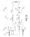
搬送波1000の発生は、電力710が発生され、そこから伝送される場所である、装置100の近位側において達成される。この電力710が、遠位側で(センサ基板760の構成部品によって)受け取られ、使用される。搬送波1000の変調は搬送波1000上にデータを重畳するために遠位の回路によって為され、それから、遠位の回路によって送られたデータを回復するために近位の回路によって復調される。図31および図32は、以下に、より詳細に記述される、搬送波1000の発生、変調、および、復調の方法を例示する。
Generation of
近位の回路(近位電気ユニット700の)による例示的な搬送波1000の発生は、電源702からの電流の引き出しによって開始する。電源702の端子は図31において「正」(正端子3100)と「負」(負端子3102)と示されている。動作の第1の段階の間、(ここではスイッチ3111とも称する)スイッチS11および(ここではスイッチ3113とも称する)スイッチS13が開いたままであるが、(ここではスイッチ3112とも称する)スイッチS12および(ここではスイッチ3114とも称する)スイッチS14は閉じられている。この段階では、電源702の正端子3100から来る電流(電力710)は、最初にスイッチS12(スイッチ3112)を通り、それからガイドワイヤ740を通って流れ、遠位の負荷に到達する。遠位の負荷を通過して、図31および図32においてISと示されている同じ電流が、(ここではスイッチ3115とも称する)通常閉じられているスイッチにS15を最初に通り、それから組織730を通って近位側(近位電気ユニット700)に戻る。ここに一般的に記述されるように、本開示の装置100全体はガイドワイヤとして構成され得、(ガイドワイヤとして構成される)装置100の「近位側」と称される近位電気ユニット700と、(ガイドワイヤとして構成される)装置100の「遠位側」と称されるセンサ基板760とを有する。その後、電流(電力710)は、(ここでは抵抗3120とも称する)抵抗RSおよびスイッチS14(スイッチ3114)を通り、バッテリ(例示的な電源702)の負端子3102に到達する。搬送波1000の発生の前記第1の段階の間、組織730は負電位であるが、「ワイヤ」(ガイドワイヤ740の、近位電気ユニット700より遠位の一部)は正電位である点に注意される。
The generation of the
例示的な搬送波1000の発生の第2の段階において、スイッチS11(スイッチ3111)およびS13(スイッチ3113)は閉じられているが、スイッチS12(スイッチ3112)およびS14(スイッチ3114)は開いたままにされる。電源702の正端子3100から来る電流が組織740に達するためにS11(スイッチ3111)およびRS(抵抗3120)を通るので、上記の構成はISの方向を逆にする。それから、この電流は、スイッチS15(スイッチ3115)、遠位の負荷、「ワイヤ」(近位電気ユニット700とセンサ基板760の間のガイドワイヤ740の部分)、そして、最後にスイッチS13(スイッチ3113)を通って、負端子3102に到達する。例示的な搬送波発生1000の第2の段階の間、組織740は正電位であるが、「ワイヤ」(近位電気ユニット700とセンサ基板760との間のガイドワイヤ740の部分)は負電位である。
両方の電位と電流ISの方向の、この交替は、例えば、搬送波1000がその交流の性質を保持することを保証する。
In the second stage of the generation of the
Direction of both the potential and the current I S, the replacement, for example, to ensure that the
図31および図32に図示されるように、搬送波1000の変調は様々の異なる構成を用いて為され得る。図31に示される構成は、直列抵抗(搬送波1000を変調するRM1(抵抗3122))を利用する。手短に言えば、スイッチS15(スイッチ3115)が閉じられると、電流ISが遭遇する抵抗は、遠位の負荷RLおよびセンサ抵抗RSのみであり、全抵抗値RL+RSを与える。もし、電源702の電圧がVPであるならば、電流ISはオームの法則を用いて発見され得る。
As illustrated in FIGS. 31 and 32, the modulation of
IS1=VP/(RL+RS) (式2) IS1 = VP / ( RL + RS ) (Expression 2)
スイッチS15(スイッチ3115)が開いているとき、電流ISは抵抗RL、RMI、および、RSを通らなければならず、全抵抗値RL+RM1+RSを与える。再び、オームの法則を用いて、電流ISの新しい値は以下の通りであると決定され得る。 When the switch S 15 to (switch 3115) is open, current I S is the resistance R L, R MI, and must pass through the R S, giving a total resistance R L + R M1 + R S . Again, using the Ohm's law, may be determined as the new value of the current I S is as follows.
IS2=VP/(RL+RM1+RS) (式3) IS2 = VP / ( RL + RM1 + RS ) (Expression 3)
式2と式3とを比較すると、式3の分母は式2の分母より大きいので、IS2がIS1より小さいと結論することができる。 Comparing Equations 2 and 3, the denominator of Equation 3 is greater than the denominator of Equation 2 can be I S2 is concluded that I S1 smaller.
抵抗RS(抵抗3120)上の電圧降下VSは、以下の通りに電流ISの両方の値について計算され得る: Voltage drop V S on resistance R S (resistor 3120) may be calculated for both values of the current I S as follows:
VS1=RS*IS1=(VP*RS)(RL+RS) (式4) VS1 = RS * IS1 = ( VP * RS ) ( RL + RS ) (Equation 4)
VS2=RS*IS2=(VP*RS)(RL+RM1+RS) (式5) VS2 = RS * IS2 = ( VP * RS ) ( RL + R M1 + RS ) (Equation 5)
また、VS2がVS1より小さいと推測されることができる。 Further, it is possible to V S2 is presumed that V S1 smaller.
搬送波の変調は、スイッチS15の開閉によって達成される。「1」に対応するデータビットを送信するために、遠位の回路はスイッチS15を閉じる。これにより、電流ISの値はIS1に、電圧降下VSはVS1に増やされる。これは近位の回路によって「1」のデータビットとして検出される。反対に、遠位の回路でスイッチS15を開くと、ISはIS2に、VSはVS2に下げられる。これにより、近位の回路によって「0」ビットが検出されることになる。 Modulation of the carrier is achieved by opening and closing of the switch S 15. To transmit the data bits corresponding to "1", the circuit of the distal closes the switch S 15. Thus, the value of the current I S to I S1, the voltage drop V S is increased to V S1. This is detected as a "1" data bit by the proximal circuit. Conversely, opening the switch S 15 in the circuit of distally, to I S is I S2, V S is lowered to V S2. This will cause the proximal circuit to detect the "0" bit.
伝統的な変調指数10%を得るために、RM1およびRSの値は、比率(IS1ーIS2)/IS1=0.1であるように選ばれることが好ましい。 In order to obtain the traditional modulation index of 10%, the values of RM1 and RS are preferably chosen such that ratio ( IS1 - IS2 ) / IS1 = 0.1.
図31に示される構成では、ゼロの伝送の間に電力の幾らかの減少が経験されるが、「1」または「ゼロ」の伝送に関係なく、常に遠位の負荷への電力の流れを許容するという長所を有する。例えば、ゼロと1の指定を逆にすることができる、そのため、S15は「ゼロ」を送信するために閉じられ、「1」を送信するために開けられる。 In the configuration shown in FIG. 31, some reduction in power is experienced during zero transmission, but the flow of power to the distal load is always present, regardless of the "1" or "zero" transmission. It has the advantage of being tolerant. For example, it is possible to specify zero and one in reverse, therefore, S 15 is closed to send a "zero", is opened in order to transmit a "1".
搬送波1000を変調するために、図32に示される概略図は、分路抵抗RM2(抵抗3200)を利用する。手短に言えば、スイッチS16(スイッチ3116)が開けられるとき、電流ISは、抵抗RLおよびRSを有する遠位の回路を流れるときに通る単一の経路のみを有する。
To modulate the
IS1=VP/(RL+RS) (式6) IS1 = VP / ( RL + RS ) (Expression 6)
VS1=RS*IS1=(Vp*Rs)/(RL+RS) (式7) V S1 = R S * I S1 = (Vp * Rs) / (R L + R S) ( Equation 7)
しかし、スイッチS16(スイッチ3116)が閉じられると、電流は2つの経路を取り、1つは遠位の負荷を通り、他の1つは抵抗RM2を通る。こうして、全抵抗を減らす。 However, when the switch S 16 (switch 3116) is closed, the current takes two paths, one through the distal load and the other through the resistor RM2 . In this way, the total resistance is reduced.
IS2=VP/(RL*RM2/(RL+RM2+RS) (式8) IS2 = VP / ( RL * R M2 / ( RL + R M2 + RS ) (Equation 8)
VS2=RS*IS2=(VP*RS)(RL*RM2(RL+RM2+RS) (式9) V S2 = R S * I S2 = (V P * R S) (RL * R M2 (R L + R M2 + R S) ( Formula 9)
この構成では、全電力が遠位の負荷に供給されることが許容され、分路抵抗RM2を通って失われないようにするために、スイッチS16(スイッチ3116)は通常開いたままにされ、先に記述された第1の構成の場合のように閉じられない。ここでも、スイッチS16が閉じられるとき、電流IS、および、対応するセンサ電圧VSは、より大きくなる。先の構成(図31)でそうであったように、ゼロまたは1を意味するスイッチ閉鎖の選択は、この構成(図32)においても任意である。 In this configuration, be allowed full power is supplied to the distal load, to prevent lost through the shunt resistor R M2, the switch S 16 (switch 3116) to leave the with normally open And not closed as in the case of the first configuration described earlier. Again, when the switch S 16 is closed, current I S, and the corresponding sensor voltage V S becomes greater. The choice of switch closure, which means zero or one, is optional in this configuration (FIG. 32), as was the case in the previous configuration (FIG. 31).
第1の構成(図31に示される)は雑音が低い状況において、より適切である。そして、変調は、搬送波1000の振幅の更なる縮小によって達成されるので、信頼できる伝送が低い変調指数で達成され得る。例えば、雑音が搬送波1000のわずか数パーセントの振幅であるならば、搬送波1000の振幅の10%の縮小は近位の回路によって容易に検出され得る。その上、スイッチS15が閉じられる時間の間に遠位の負荷に供給される電力を約10%減らすので、(図31に示される)第1の構成を使用するのが好適である。
The first configuration (shown in FIG. 31) is more suitable in low noise situations. And since the modulation is achieved by further reducing the amplitude of the
固有の雑音レベルが高いときは、(図32に示される)第2の構成が好適である。この構成は、電流およびセンサ電圧を増やすことによる変調を用いて雑音を克服する。しかし、それは、データ伝送の間に遠位の負荷に供給されている電流を激減させることとのトレードオフである。 When the inherent noise level is high, the second configuration (shown in FIG. 32) is preferred. This configuration overcomes noise by using modulation by increasing the current and sensor voltage. However, it is a trade-off with depleting the current supplied to the distal load during data transmission.
例示的な集積回路(ここで例示的な回路モジュール104と称されるICまたはASIC)は、本開示のセンサ基板760内に含まれる様々の構成部品を含むことができる。更にまた、本開示の様々の回路モジュール104は、以下に限られていないが、例えば、以下のタスク/機能を実行するように構成されることができ、および/または、そのように動作可能であることができる。
a)(センサ基板760に属する、センサ基板760内の、或いは、センサ基板760に接続された)遠位の回路の動作のために必要である直流電源を生成するために、近位の回路(近位電気ユニット700)から来る交流電力の整流、および/または、
b)リップルを減らして、遠位の回路の構成部品によって必要とされる定電圧電源を提供する直流電力の調整、および/または
c)遠位の回路から近位の回路へのデータの伝送のための搬送波1000の変調、および/または
d)近位の回路による電力の中断の検出(遠位の回路が、遠位の回路に存在するセンサ(サイジング部120および/またはセンサ130)を用いてデータを収集することが安全なことを知らせる)、および/または
e)電力蓄積コンデンサ(コンデンサ762)と、圧力センサ(例示的なセンサ130)と、(他の1つの例示的なセンサ130)温度センサと、(例えば、電極122、124、126、128のような)インピーダンス・センサとを含む、遠位先端内の全ての回路およびセンサの動作を制御する、および/または
f)近位の回路に戻され得る診断情報を生成する、および/または
g)センサおよび(増幅器914のような)オンボード増幅器への必要なオフセット電圧を発生する、および/または
h)トランスジューサからデータへの搬送波1000の干渉を減らすために、それぞれのセンサ計測の間と後に、分離スイッチ(スイッチ930および932、および/または、ここに記述される他のスイッチ)をオン、オフする、および/または
i)インピーダンス・センサ(サイジング部120)の電極126、128、および、圧力センサおよび温度センサのブリッジ回路内にある歪みゲージへの交流付勢を含み、(例えば、電極126、128のような)センサの動作に必要な励起を発生する、および/または
j)例えば、1または複数の増幅器914の動作を指示し、及び/又は、調整することによって、センサから戻る信号を増幅する、および/または
k)前記センサから戻る信号を正確な時にサンプリングする、および/または
1)(例えば、アナログデジタルアナログデジタル922の動作を指示し、及び/又は、調整することによって、)センサから来るアナログ信号をデジタル形式に変換する、および/または
m)例えば、回路モジュール104および/またはセンサ基板760の他の構成部品に接続している、メモリ964(本開示の例示的な記憶媒体)内に、デジタルのセンサ・データを格納する(これにより、データが近位の回路に送られ得るまで、メモリ964はデータを格納することができる)、および/または
n)(例えば、ここに記述されるようにデータを送信するように構成された、有線または無線通信モジュール600、或いは、装置100の他の一部の動作を管理し、及び/又は、制御することによって、)近位の回路へデータを送信する、および/または
o)無線周波数電磁波を用いて近位の回路によって伝送される電力を回復するために、オプションの無線周波数(RF)構成部品に接続する、および/または
p)無線周波数電磁波を用いてデータを近位の回路へ送信するために、オプションの無線周波数(RF)構成部品に接続する、および/または
q)近位電気ユニット700からの電力が導体106へと流れるのを一時的に止めたと認識する、および/または
r)導体106に供給されるのを一時的に止めるために、近位電気ユニット700からの電力を管理する。
An exemplary integrated circuit (IC or ASIC referred to herein as an exemplary circuit module 104) can include various components contained within the
a) A proximal circuit (belonging to the
b) Adjustment of DC power to reduce ripple and provide the constant voltage power supply required by the components of the distal circuit, and / or c) Transmission of data from the distal circuit to the proximal circuit. Modulation of
上記のように、回路モジュール104内の固有の構成部品、および/または、例えば、センサ基板760に関連して様々の図に示されるような回路モジュール104と通信する構成部品を用いて、以下の機能/タスクの1または複数を完了することができる。
As described above, using the unique components within the
ここに一般に記述されるように、そして、本開示の装置100を用いる少なくとも1つの実施の形態において、(ここに記述される半ホイートストン・ブリッジのような)圧力センサ130の部分がサーミスタとして使用されることができる。或いは、例えば、注入されたボーラスの温度、または、血液の温度に基づく前記センサの加温または冷却に基づく閾値温度のような、温度データを得るために、別のサーミスタ(センサ)が使用され得る。そのような閾値温度は、例えば、温度データを受け取った後の回路モジュール104の指示によって、サイジング部120および/またはセンサ130のうちの1または複数の測定値を得るための動作の引き金となることができる。導体106を介して電力をセンサ基板760に供給することを一時的に止めるように近位電気ユニット700に指示するために回路モジュール104が電力信号上の搬送波1000を介して信号を届けた後にも、動作トリガが行われ得る。或いは、データが得られ、及び/又は、近位電気ユニット700に送られる間、回路モジュール106は電力をオフとするように動作することができる。
As commonly described herein, and in at least one embodiment using the
本開示の装置100の少なくとも1つの実施の形態においては、(センサ基板760に属する、或いは、センサ基板760に接続された)遠位の構成部品は、図33に示されるように、データが電磁的に送られる間にガイドワイヤ740(装置100の一部)および組織730によって形成される回路を通って届けられる電流ISによって電力供給される。そのような実施の形態においては、搬送波1000は装置100の遠位端構成部品によって変調されない。しかし、搬送波1000からの干渉なしにセンサ(例えば、サイジング部120および/または1または複数のセンサ130)によって測定を行うことが安全なことを遠位の回路に知らせるために周期的に中断される。結果として得られるデータは、図33に示されるように、有線または無線通信モジュール600に属するか、または、有線または無線通信モジュール600に接続される遠位部アンテナ3300から、近位電気ユニット700に属するか、または、近位電気ユニット700内にあるか、または、近位電気ユニット700に接続される受信器3304の近位部アンテナ3302へ送られるようにして、無線周波数電磁波3350を用いて近位電気ユニット(700)へ送られる。適しており、規制機関によって許される、如何なる周波数によっても伝送は為され得るが、組織730による吸収が高い周波数は避けられるべきである。更にまた、より高い周波数はより短い波長を必要とし、それ故に、様々の実施の形態において、より短いアンテナ3300、3302の長さが好ましい。しかし、高周波において組織730の吸収度は増加し得る。10KHzから100MHzの範囲の周波数が使用され得るが、使用される実施の形態によれば、64MHz周辺の周波数が好まれ得る。
振幅変調、周波数変調、および、パルス位置変調を含む、ここに記述される既知の変調構成の何れによってでもデータ伝送は達成され得る。これらは、例えば、時分割多重化を用いてアナログ形式でセンサ・データを伝送するために使用され得る変調構成の例である。同様に、振幅偏移変調、周波数偏移変調、および、位相偏移変調が、デジタルデータの伝送のために使用され得る。周波数分割多重化のような、情報伝送のために使用され得る他のデータ技術は全て本開示の範囲内にある。
In at least one embodiment of the
Data transmission can be achieved by any of the known modulation configurations described herein, including amplitude modulation, frequency modulation, and pulse position modulation. These are, for example, examples of modulation configurations that can be used to transmit sensor data in analog format using time division multiplexing. Similarly, amplitude shift keying, frequency shift keying, and phase shift keying can be used for the transmission of digital data. All other data technologies that can be used for information transmission, such as frequency division multiplexing, are within the scope of this disclosure.
図33に示される、この構成は、更に、付加的データが同じRFチャネルを用いて近位ユニットから遠位ユニットに送られることを許容する。 This configuration, shown in FIG. 33, further allows additional data to be sent from the proximal unit to the distal unit using the same RF channel.
本開示の更なる実施の形態においては、遠位先端は組織730を通って供給されるRF電力によって電力供給される、そして、図34に示されるように、データも電磁的に後方に送られる。この場合、ガイドワイヤ740と組織730とによって形成される電気ループの必要がない。そして、分離スイッチ(スイッチ930、932)は遠位の回路から除かれる。更にまた、搬送波1000が近位の回路から送られないので、遠位の回路上の変調器も近位の回路上の復調器もない。その代わりに、近位ユニットから遠位ユニットまで電力710を伝送して、遠位の回路から近位の回路までデータ信号765を戻すために、近位の回路にあって受信器3304と名付けられるものと、遠位の回路にあって有線または無線通信モジュール600と名付けられるものとの2つのRFユニットが用いられる。
In a further embodiment of the present disclosure, the distal tip is powered by RF power delivered through
電力およびデータのRFベースの伝送のためにカスタム回路を作ることができるが、13MHzから900MHzに亘る異なる周波数で動作するRFIDチップを使用することもできる。そのような実施の形態においては、ガイドワイヤ(すなわち、アンテナ3302を備える有線または無線通信モジュール600)の遠位の部分に配置されるRFID装置は、入って来るRF信号から電力を回収して、回路モジュール104を作動させるために回路モジュール104に電力を提供する。それから、RFIDチップはまた、データを近位のユニットに返す。
Custom circuits can be made for RF-based transmission of power and data, but RFID chips operating at different frequencies ranging from 13 MHz to 900 MHz can also be used. In such an embodiment, an RFID device located in the distal portion of a guide wire (ie, a wired or
効率的に電力を伝送して、確実にデータを受け取るために、近位の回路または少なくとも受信器3304のアンテナ3302は、ガイドワイヤの遠位先端の近くに配置される必要があり得る。
To efficiently transmit power and reliably receive data, the proximal circuit or at least the
遠位先端にある(センサ基板760に属する、或いは、センサ基板760内にある、或いは、センサ基板760に接続された)回路が、医療装置100上に存在する(サイジング部120および/または他のセンサ130のような)センサを走査して、それらを順次適切な時にサンプリングする。トランスジューサ・データを生成するために上記センサを作動させる時は、(近位電気ユニット700に属する、近位電気ユニット700内にある、或いは、近位電気ユニット700に接続される)近位の回路の動作によって決定される。ここに一般的に記述されるように、近位の回路は、搬送波1000の発生を停止することにより、遠位の回路への全電力の伝送を周期的に中断する。遠位の回路は、搬送波1000の可用性を連続的にモニタして、搬送波1000の欠如を、順番において次のセンサを作動させて測定をする時であるという指示として解釈する。搬送波1000の欠如は、遠位の回路が測定モード(これにより、サイジング部120および/またはセンサ130がサイジング、圧力、および/または、温度データを得るために動作する)に切替わるトリガとして用いられるだけでなく、搬送波1000によって組織730内で誘発される電気的干渉がない環境を作ることを実現可能にする。遠位の回路は、測定を行うためにボード上のセンサを循環させることを許容する(回路モジュール104内の、或いは、回路モジュール104によって制御されるような)カウンタを有する。近位の搬送波1000の停止によって作られる測定期間は、遠位の回路が、センサおよび関連電子増幅器914を作動させ、これらが安定するのを待ち、信頼できる測定値を得、結果として生じるデータをオンボードアナログ/デジタル変換器(ADC)922を用いてデジタル形式に変換するためには十分に長い。最後に、一旦搬送波1000が近位の回路で回復すると、結果として生じるデータは搬送波1000の変調によって近位の回路へ送られる。
A circuit at the distal tip (belonging to or within the
本開示の様々の装置100および/またはシステム300は様々の式および/またはアルゴリズムを使用し得る。これらは、例えば、オームの法則、および/または、以下の参照文献の1または複数に記述されるように、電界内で1または複数の食塩水注入等を検出するために使用される(例えば、2つの検出電極122、124の間の距離のような)2つの電極の間の距離である。ここで、前記装置100および/またはシステム300は以下の手順/タスクの1または複数を実行するように構成される。
(a)例えば、Kassab他への米国特許第7,454,244号、Kassab他への米国特許第8,114,143号、Kassab他への米国特許第8,082,032号、Kassabの米国特許出願公開番号第2010/0152607号、Kassabの米国特許出願公開番号第2012/0053441号、Kassab他の米国特許出願公開番号第2012/0089046号、Kassab他の米国特許出願公開番号第2012/0143078号、および、Kassabの米国特許出願公開番号第2013/0030318号(これらの内容の全ては、この参照によって本開示に含むものとする)に記述されているように、哺乳類の管腔臓器のサイズ(例えば、断面積または直径)、哺乳類の管腔臓器内の並列組織コンダクタンス、および/または、管腔臓器内の装置のナビゲーションを決定すること、
(b)例えば、Kassabの米国特許出願公開番号第2009/0182287号、Kassabの米国特許出願公開番号第2012/0172746号、Kassabへの米国特許第8,078,274号、および、Kassabの米国特許第8,632,469号(これらの内容の全ては、この参照によって本開示に含むものとする)に記述されているように、1または複数の体内管腔合流箇所の位置、および/または、管腔臓器の断面形状を決定すること、
(c)Kassabの米国特許出願公開番号第2009/0182287号、Kassabの米国特許出願公開番号第2010/0222786号、Kassabの米国特許出願公開番号第2013/0282037号、および、Kassabの米国特許第8,465,452号(これらの内容の全ては、この参照によって本開示に含むものとする)に記述されているように、哺乳類の患者内の組織を切除すること、および/または血管から狭窄性病変を取り除くこと、
(d)例えば、Kassabの米国特許出願公開番号第2010/0152607号、Kassabの米国特許出願公開番号第2011/0034824号、および、Kassabへの米国特許第7,818,053号(これらの内容の全ては、この参照によって本開示に含むものとする)に記述されているように、管腔臓器内のプラークの存在、可能性のある種類、および/または、脆弱さを決定すること、
(e)例えば、Kassabへの米国特許番号8,185,194号および米国特許第8,099,161号(これらの内容の全ては、この参照によって本開示に含むものとする)に記述されているように、位相性心周期の測定値を決定して、血管のコンプライアンスを決定すること、
(f)例えば、Kassabへの米国特許番号8,078,274号と、Kassabの米国特許出願公開番号第2010/0152607号、Kassab他の米国特許出願公開番号第2012/0053441号、および、Kassab他の米国特許出願公開番号第2012/0089046号(これらの内容の全ては、この参照によって本開示に含むものとする)に記述されているように、哺乳類の管腔臓器を通って流れる流体の速度を決定すること、
(g)例えば、Kassabの米国特許出願公開番号第2013/0317392号およびKassabへの米国特許第8,406,867号(これらの内容の全ては、この参照によって本開示に含むものとする)に記述されているような、(例えば、経皮的バルブの弁輪のサイジングのような)インピーダンスおよびバルーンを用いるバルブのサイジング、
(h)例えば、Kassabへの米国特許第8,388,604号(この内容の全ては、この参照によって本開示に含むものとする)に記述されているように、哺乳類の管腔臓器から造影剤を検出し、及び/又は、除去すること、
(i)例えば、Kassabの米国特許出願公開番号第2011/0178417号およびKassabの米国特許出願公開番号第2011/0178383号(これらの内容の全ては、この参照によって本開示に含むものとする)に記述されているように、冠血流予備量比を決定すること、および/または
(j)例えば、哺乳類の管腔臓器を通して関心対象の位置まで誘導するために本開示の装置100を用い、そして、前記管腔臓器内にリードを配置するために装置100および/または第2の装置を用いることにより、哺乳類の管腔臓器内に導線を配置すること。
The
(A) For example, US Pat. No. 7,454,244 to Cassab et al., US Pat. No. 8,114,143 to Cassab et al., US Pat. No. 8,082,032 to Cassab et al., USA of Cassab et al. Patent Application Publication No. 2010/015267, Kassab U.S. Patent Application Publication No. 2012/0053441, Kassab et al. U.S. Patent Application Publication No. 2012/00890446, Kassab et al. U.S. Patent Application Publication No. 2012/0143078 , And, as described in Kassab's US Patent Application Publication No. 2013/0030318, all of which is incorporated herein by reference (eg, the size of the mammalian luminal organs). Determining cross-sectional area or diameter), parallel tissue conductance within the mammalian luminal organ, and / or navigation of the device within the luminal organ,
(B) For example, Kassab's U.S. Patent Application Publication No. 2009/018287, Kassab's U.S. Patent Application Publication No. 2012/0172746, Kassab's U.S. Patent No. 8,078,274, and Kassab's U.S. Patent. The location and / or cavity of one or more body lumen confluences, as described in No. 8,632,469 (all of which is incorporated herein by this reference). Determining the cross-sectional shape of an organ,
(C) Kassab U.S. Patent Application Publication No. 2009/018287, Kassab U.S. Patent Application Publication No. 2010/0222786, Kassab U.S. Patent Application Publication No. 2013/0282037, and Kassab U.S. Patent No. 8 , 465, 452, all of which are incorporated herein by reference), excision of tissue within a mammalian patient, and / or stenotic lesions from a blood vessel. To get rid of
(D) For example, Kassab's U.S. Patent Application Publication No. 2010/015267, Kassab's U.S. Patent Application Publication No. 2011/0034824, and Kassab's U.S. Patent No. 7,818,053 (of these contents). Determining the presence, possible types, and / or vulnerabilities of plaques within luminal organs, as described in this disclosure, all of which is incorporated herein by reference.
(E) As described, for example, in US Pat. Nos. 8,185,194 and US Pat. No. 8,099,161 to Cassab, all of which are incorporated herein by reference. To determine vascular compliance by determining phased cardiac cycle measurements,
(F) For example, US Patent No. 8,078,274 to Cassab, US Patent Application Publication No. 2010/015267 of Cassab, US Patent Application Publication No. 2012/0053441 of Cassab et al., And Cassab et al. Determines the rate of fluid flowing through a mammalian luminal organ, as described in U.S. Patent Application Publication No. 2012/00890446, all of which are incorporated herein by reference. To do,
(G) described, for example, in US Patent Application Publication No. 2013/0317392 of Cassab and US Pat. Nos. 8,406,867 to Cassab, all of which are incorporated herein by reference. Valve sizing with impedance and balloons, such as (eg, percutaneous valve annulus sizing).
(H) Contrast agents from mammalian luminal organs, for example, as described in US Pat. No. 8,388,604 to Cassab, all of which is incorporated herein by reference. To detect and / or remove,
(I) For example, described in Kassab's U.S. Patent Application Publication No. 2011/01778417 and Kassab's U.S. Patent Application Publication No. 2011/0178383, all of which are incorporated herein by reference. As such, the
前述に加えて、本開示の様々の装置100、および、前述の特許および/または特許出願の1または複数に記述された様々の他のインピーダンス装置(例えば、4極性装置のような)は、例えば、静脈瘤の静脈不全の治療(整形外科的な処置)のための血管内レーザ治療(Endovascular Laser Therapy(EVLT))のために哺乳類の管腔臓器を通って誘導するためのように、比較的小さな静脈の1または複数の切除を実行するように動作可能であり、及び/又は、尿道/膀胱移行部、子供たちの先天性異常の輸尿管の狭窄、輸尿管に対する子宮の圧縮による妊婦の輸尿管の拡張、骨盤骨折を伴う外傷、および、他の泌尿器科学状況を評価するように、更に、輸尿管狭窄症を(腎臓から出ている輸尿管のレベルを含む)様々なレベルで評価するように動作可能であり得る。
In addition to the above, the
集積回路モジュール付きのインピーダンス装置の様々の実施の形態、おび、これらの装置を使用する方法が、ここに、かなり詳細に記述されるが、これらの実施の形態はここに記述される開示の単に非限定的な例として提供されるだけである。したがって、様々の変更及び改造がなされ得ると理解されるべきであり、本開示の要旨を逸脱しない範囲で、それらの構成要素は等価物によって置き換えられ得る。本開示は、その内容に関して、網羅的もしくは限定的であることを意図しない。 Various embodiments of impedance devices with integrated circuit modules, and methods of using these devices, are described here in considerable detail, but these embodiments are merely disclosures described herein. It is provided only as a non-limiting example. It should therefore be understood that various modifications and modifications may be made and their components may be replaced by equivalents without departing from the gist of the present disclosure. This disclosure is not intended to be exhaustive or limited in its content.
更に、代表的な実施の形態を記述する際に、本開示では、方法および/またはプロセスを特定のステップ・シーケンスとして提示したかもしれない。しかし、方法またはプロセスが、その中に記述された特定のステップ順に依存しないならば、その方法またはプロセスは、記述された特定のステップ・シーケンスに限定されるべきではなく、他のステップ・シーケンスが可能であり得る。したがって、ここに開示された特定のステップ順は、本開示の限定と解釈されてはならない。更に、方法および/またはプロセスを対象とする開示は、それらのステップを記載された順に実行することに限定されるべきではない。そのようなシーケンスは様々であり得るが、依然、本開示の範囲内にある。
下記は、当初より本願に記載されていた発明である。
<請求項1>
患者の哺乳類管腔臓器に少なくとも部分的に挿入するために構成された細長ボディであって、前記細長ボディは、前記細長ボディを通って延びる第1の導体を有する、該細長ボディと、
前記細長ボディに動作可能に接続され、前記第1の導体に沿って電力を配給するように構成された近位電気ユニットと、
前記細長ボディの遠位端部に、又は、その近くに位置するセンサ基板であって、前記センサ基板は、前記第1の導体を通して配給される前記電力から直接又は間接的に電力供給を受けるサイジング部および圧力センサに動作可能に接続される、該センサ基板を有し、
前記回路モジュールが、
a) サイジング・データを取得するように前記サイジング部の動作を指示し、
b) 前記圧力センサに圧力データを取得するように指示し、
c) 前記サイジング・データおよび/又は前記圧力データの前記近位電気ユニットへの伝送を容易化する
ように動作可能で、及び/又は、そのように構成されたインピーダンス装置。
<請求項2>
前記第1の導体は単一の導体を有し、前記回路モジュールは、前記第1の導体に沿って配給される電力を用いて、サイジング・データを取得するように前記サイジング部の動作を指示し、圧力データを取得するように前記圧力センサに指示し、前記サイジング・データおよび/又は前記圧力データの前記近位電気ユニットへの伝送を容易化するように動作可能である請求項1に記載のインピーダンス装置。
<請求項3>
前記センサ基板は、前記細長ボディの第1の位置における、断面積、及び/又は、断面積に対応する直径、及び/又は、直径のうちの少なくとも1つを有する請求項1に記載のインピーダンス装置。
<請求項4>
前記センサ基板は、前記近位電気ユニットから前記電力を得るように構成されるコンデンサを更に有する請求項1に記載のインピーダンス装置。
<請求項5>
前記センサ基板は、コンデンサを充電するように構成された遠位電源を更に含む請求項4に記載のインピーダンス装置。
<請求項6>
前記回路モジュールは前記近位電気ユニットからの電力から給電される請求項1に記載のインピーダンス装置。
<請求項7>
前記回路モジュールは、前記センサ基板の遠位電源によって給電され、前記遠位電源は、前記第1の導体を介して、及び/又は、前記遠位電源に接続されるコンデンサから、配給される電力を用いて前記回路モジュールに給電するように構成され、前記遠位電源は、前記配給される電力を前記第1の導体を介して受けるように構成される請求項1に記載のインピーダンス装置。
<請求項8>
前記サイジング部は、1対の励起電極の間に配置された1対の検出電極を有し、前記1対の励起電極は、前記1対の検出電極によって検出可能な電界を発生するように構成される請求項1に記載のインピーダンス装置。
<請求項9>
前記サイジング部は前記センサ基板に直接接続される請求項8に記載のインピーダンス装置。
<請求項10>
前記サイジング部は、前記細長ボディの、前記センサ基板より遠位の部分の上に配置される請求項8に記載のインピーダンス装置。
<請求項11>
前記サイジング部および前記圧力センサは、前記センサ基板の上に、又は、前記センサ基板内に配置されるマルチプレクサに、各々、動作可能に接続される請求項1に記載のインピーダンス装置。
<請求項12>
第1の増幅器が前記サイジング部と前記マルチプレクサとの間に配置され、少なくとも1つの第2の増幅器が前記圧力センサとマルチプレクサの間に配置され、前記第1の増幅器が前記サイジング・データを増幅するように構成され、前記第2の増幅器が前記圧力データを増幅するように構成される請求項11に記載のインピーダンス装置。
<請求項13>
前記マルチプレクサは、前記サイジング部からサイジング・データを、そして、前記圧力センサから圧力データを受け取るように構成され、前記サイジング・データおよび前記圧力データを、別々に、前記回路モジュールに送信するように更に構成される請求項11に記載のインピーダンス装置。
<請求項14>
前記マルチプレクサは、前記サイジング部からサイジング・データを、そして、前記圧力センサから圧力データを受け取るように構成され、前記回路モジュールへの伝送のために、前記センサ基板の上に、又は、前記センサ基板内に配置されたアナログ/デジタル変換器に前記サイジング・データおよび前記圧力データを最初に送信するように更に構成される請求項11に記載のインピーダンス装置。
<請求項15>
前記アナログ/デジタル変換器は、前記サイジング・データおよび前記圧力データを、アナログデータからデジタルデータに変換するように構成される請求項14に記載のインピーダンス装置。
<請求項16>
前記センサ基板は、前記サイジング・データ及び/又は前記圧力データの前記近位電気ユニットへの伝送を、前記センサ基板に接続された金属エレメントによって容易化し、前記金属エレメントは、前記サイジング・データ及び/又は前記圧力データを、前記哺乳類管腔臓器に隣接する組織を通して、前記患者の皮膚上に置かれるパッドに送信するように構成される請求項1に記載のインピーダンス装置。
<請求項17>
前記金属エレメントは、前記センサ基板に接続された遠位接地を有する請求項1に記載のインピーダンス装置。
<請求項18>
前記金属エレメントは前記サイジング部の電極を有する請求項1に記載のインピーダンス装置。
<請求項19>
前記金属エレメントは前記圧力センサを含む請求項1に記載のインピーダンス装置。
<請求項20>
前記金属エレメントは、前記センサ基板に接続され、又は、前記センサ基板内の送信器を有する請求項1に記載のインピーダンス装置。
<請求項21>
前記細長ボディと前記回路モジュールとの間に配置された第1のスイッチを更に有する請求項1に記載のインピーダンス装置。
<請求項22>
前記センサ基板の遠位電源と前記センサ基板に接続された遠位接地との間に配置された第2のスイッチを更に有する請求項21に記載のインピーダンス装置。
<請求項23>
前記近位電気ユニットからの電力は前記近位電気ユニットの電源によって配給される請求項1に記載のインピーダンス装置。
<請求項24>
前記細長ボディは、該細長ボディの中を通して延びる第2の導体を更に有し、前記近位電気ユニットから前記センサ基板まで、前記第1の導体を用いて電力が配給され、前記センサ基板から前記近位電気ユニットまで、前記第2の導体を用いて、前記サイジング・データ及び/又は前記圧力データが送られる請求項1に記載のインピーダンス装置。
<請求項25>
前記細長ボディは、その中を前記第1の導体が貫通して延びる近位セグメントを有し、前記近位セグメントは内側セグメントに接続されるように構成された請求項1に記載のインピーダンス装置。
<請求項26>
前記近位セグメントは前記内側セグメントに接続され、前記内側セグメントは遠位セグメントに接続されるように構成される請求項25に記載のインピーダンス装置。
<請求項27>
前記センサ基板は内側セグメント内にフィットする(ぴったり合う)ように構成される請求項26に記載のインピーダンス装置。
<請求項28>
前記第1の導体は、前記細長ボディの近位セグメント内に配置され、前記近位セグメントは、更に遠位セグメントに接続された内側セグメントに接続される請求項1に記載のインピーダンス装置。
<請求項29>
前記内側セグメントは前記センサ基板を含む請求項28に記載のインピーダンス装置。
<請求項30>
前記回路モジュールおよび前記圧力センサは、コンポーネント・ハウジング内にフィットするように構成され、前記コンポーネント・ハウジングは前記内側セグメント内にフィットするように構成される請求項28に記載のインピーダンス装置。
<請求項31>
前記回路モジュールに接続されたコンデンサを更に含む請求項30に記載のインピーダンス装置。
<請求項32>
前記コンデンサは、前記コンポーネント・ハウジング内にフィットするように構成される請求項31に記載のインピーダンス装置。
<請求項33>
前記圧力センサ、前記回路モジュール、および、前記コンデンサのうちの少なくとも1つに接続された転送回路を更に有し、前記転送回路は、そこに配置される少なくとも1つの構成要素に電気的に接続されるように構成される請求項31に記載のインピーダンス装置。
<請求項34>
前記細長ボディの少なくとも第1の位置の部分の周りに巻きつくように構成されたラップを更に含む請求項1に記載のインピーダンス装置。
<請求項35>
前記サイジング部は、前記サイジング・データを取得するように構成された複数の電極を有し、前記複数の電極は、前記ラップに接続されるか、又は、前記ラップの部分として形成される請求項34に記載のインピーダンス装置。
<請求項36>
前記ラップが前記細長ボディの少なくとも前記第1の位置の部分の周りに配置されるとき、前記複数の電極のうちの少なくとも1つが前記回路モジュールに電気的に接続される請求項35に記載のインピーダンス装置。
<請求項37>
前記第1の導体は前記細長ボディの近位セグメント内に配置され、前記近位セグメントは、遠位セグメントに更に接続された内側セグメントに接続される請求項36に記載のインピーダンス装置。
<請求項38>
前記回路モジュールおよび前記圧力センサはコンポーネント・ハウジング内にフィットするように構成され、前記コンポーネント・ハウジングは、内側セグメント内にフィットするように構成される請求項37に記載のインピーダンス装置。
<請求項39>
前記近位電気ユニットから配給される電力は交流電力であり、前記回路モジュールは更に、前記サイジング部及び/又は前記圧力センサを作動させるための直流電力を発生するために交流を整流するように動作可能である請求項1に記載のインピーダンス装置。
<請求項40>
前記回路モジュールは更に、電力のリップルを減らして、定電圧電源を前記サイジング部及び/又は前記圧力センサに提供するために直流電力を調整するように動作可能である請求項39に記載のインピーダンス装置。
<請求項41>
前記回路モジュールは更に、前記サイジング・データ及び/又は前記圧力データを前記近位電気ユニットに送信するために用いられる搬送波を変調するように動作可能である請求項1に記載のインピーダンス装置。
<請求項42>
前記回路モジュールは更に、前記近位電気ユニットからの電力の中断を検出するように動作可能である請求項1に記載のインピーダンス装置。
<請求項43>
前記回路モジュールは更に、前記サイジング部と、前記圧力センサと、温度データを取得するように動作可能な前記センサ基板内の温度センサと、前記センサ基板内の電源に動作可能に接続される前記センサ基板内のコンデンサとの動作を制御するように動作可能である請求項1に記載のインピーダンス装置。
<請求項44>
前記回路モジュールは更に、前記近位電気ユニットへの伝送のために、前記サイジング・データ及び/又は前記圧力データを用いて診断情報を生成するように動作可能である請求項1に記載のインピーダンス装置。
<請求項45>
前記回路モジュールは更に、前記サイジング部及び/又は前記圧力センサに対するオフセット電圧、及び、前記サイジング部及び/又は前記圧力センサに接続された任意の増幅器に対するオフセット電圧を発生するように動作可能である請求項1に記載のインピーダンス装置。
<請求項46>
前記センサ基板は更に、コンデンサに接続された電源と、接地された第1のスイッチと、前記第1の導体に接続された第2のスイッチとを更に含み、前記回路モジュールは更に、前記サイジング部及び/又は前記圧力センサの動作の間および後に前記第1のスイッチ及び/又は前記第2のスイッチの動作を制御するように動作可能である請求項1に記載のインピーダンス装置。
<請求項47>
前記回路モジュールは更に、前記サイジング部の1又は複数の励起電極への前記直流電力の配給を制御するように動作可能である請求項39に記載のインピーダンス装置。
<請求項48>
前記回路モジュールは更に、前記サイジング部の1又は複数の励起電極への前記直流電力の配給を制御するように動作可能である請求項39に記載のインピーダンス装置。
<請求項49>
前記回路モジュールは更に、前記サイジング・データ及び/又は前記圧力データの増幅を制御するように動作可能である請求項1に記載のインピーダンス装置。
<請求項50>
前記制御は、前記回路モジュールと、前記サイジング部及び/又は前記圧力センサに接続された1又は複数の増幅器とによって実行される請求項39に記載のインピーダンス装置。
<請求項51>
前記回路モジュールは更に、前記サイジング部からの前記サイジング・データ、及び/又は、前記圧力センサからの前記圧力データを、正しい時期にサンプリングするように動作可能である請求項1に記載のインピーダンス装置。
<請求項52>
前記サイジング部からの前記サイジング・データおよび前記圧力センサからの前記圧力データはアナログ信号であり、前記回路モジュールは更に、アナログ信号をデジタル信号に変換するように動作可能である請求項1に記載のインピーダンス装置。
<請求項53>
前記変換は、前記回路モジュールと、前記回路モジュールに直接又は間接的に接続されたアナログ/デジタル変換器とによって実行される請求項52に記載のインピーダンス装置。
<請求項54>
前記回路モジュールは更に、前記サイジング・データ及び/又は前記圧力データの記憶を制御するように動作可能である請求項1に記載のインピーダンス装置。
<請求項55>
前記記憶は、前記回路モジュールと、前記回路モジュールに直接又は間接的に接続されたメモリとによって実行される請求項54に記載のインピーダンス装置。
<請求項56>
前記回路モジュールは更に、前記サイジング・データ及び/又は前記圧力データの前記近位電気ユニットへの伝送を調整するように動作可能である請求項1に記載のインピーダンス装置。
<請求項57>
前記調整は、前記回路モジュールと、前記回路モジュールに直接又は間接的に接続された有線又は無線通信モジュールとによって実行される請求項54に記載のインピーダンス装置。
<請求項58>
前記回路モジュールは更に、無線周波数電磁波を用いて前記近位電気ユニットによって配給された前記電力を回収するために、前記センサ基板内の1又は複数の無線周波数構成部品に接続するように動作可能である請求項1に記載のインピーダンス装置。
<請求項59>
前記回路モジュールは更に、前記サイジング・データ及び/又は前記圧力データを無線周波数電磁波を用いて前記近位電気ユニットに送信するために、前記センサ基板内の1又は複数の無線周波数構成部品に接続するように動作可能である請求項1に記載のインピーダンス装置。
<請求項60>
前記圧力センサは更に、温度データを取得するように動作可能である請求項1に記載のインピーダンス装置。
<請求項61>
前記センサ基板は更に温度センサを有し、前記回路モジュールは更に、温度データを取得し、前記近位電気ユニットへの前記温度データの伝送を容易化するように、前記温度センサに対して指示するように動作可能であり、及び/又は、そのように構成された請求項1に記載のインピーダンス装置。
<請求項62>
前記細長ボディおよび前記センサ基板は、各々、0.014インチ以下の外径を有する請求項1に記載のインピーダンス装置。
<請求項63>
前記細長ボディおよび前記センサ基板はガイドワイヤとして構成される請求項1に記載のインピーダンス装置。
<請求項64>
ガイドワイヤとして構成される請求項1に記載のインピーダンス装置。
<請求項65>
前記近位電気ユニットは前記細長ボディのためのハンドルとして構成される請求項1に記載のインピーダンス装置。
<請求項66>
前記近位電気ユニットはコンピュータ・コンソールとして構成される請求項1に記載のインピーダンス装置。
<請求項67>
前記回路モジュールは、無線で前記サイジング・データ及び/又は前記圧力データを前記近位電気ユニット、又は、それに接続された構成部品に送信するように構成された無線通信モジュールの動作を指示することによって、前記サイジング・データ及び/又は前記圧力データの前記近位電気ユニットへの伝送を容易化するように動作可能であり、及び/又は、そのように容易化するように構成された請求項1に記載のインピーダンス装置。
<請求項68>
前記無線通信モジュールは、無線周波数信号を使用して前記サイジング・データ及び/又は前記圧力データを無線送信するように構成される請求項67に記載のインピーダンス装置。
<請求項69>
前記回路モジュールは更に、前記サイジング・データ及び/又は前記圧力データの生成の間、前記サイジング部および前記圧力センサへの電力の配給を一時的に止めるように動作可能であり、及び/又は、そのように構成された請求項1に記載のインピーダンス装置。
<請求項70>
前記回路モジュールは更に、前記サイジング・データ及び/又は前記圧力データの生成の間、前記第1の導体を通して前記センサ基板に配給される電力の伝送を一時的に止めるように動作可能であり、及び/又は、そのように構成された請求項1に記載のインピーダンス装置。
<請求項71>
前記回路モジュールが前記近位電気ユニットから電力の一時的な停止を識別すると、前記サイジング部は前記サイジング・データを取得するように動作し、前記圧力センサは前記圧力データを取得するように動作するように構成された請求項1に記載のインピーダンス装置。
<請求項72>
前記近位電気ユニットを有するマイクロプロセッサが、前記第1の導体への電力の配給を調整する請求項1に記載のインピーダンス装置。
<請求項73>
前記マイクロプロセッサが前記第1の導体への電力の配給を一時的に止めると、前記サイジング部が前記サイジング・データを取得するようにトリガされ、及び/又は、前記圧力センサが前記圧力データを取得するようにトリガされる請求項72に記載のインピーダンス装置。
<請求項74>
前記回路モジュールは更に、前記第1の導体への電力の配給を一時的に止めるように前記マイクロプロセッサに指示するように動作可能であり、及び/又は、そのように構成された請求項72に記載のインピーダンス装置。
<請求項75>
前記回路モジュールは更に、前記第1の導体への電力の配給の一時的な停止を識別するように動作可能であり、及び/又は、そのように構成された請求項74に記載のインピーダンス装置。
<請求項76>
前記回路モジュールは更に、前記第1の導体への電力の配給の一時的な停止を認識した後に、前記サイジング部に前記サイジング・データを取得するように指示し、及び/又は、前記圧力センサに前記圧力データを取得するように指示するように動作可能であり、及び/又は、そのように構成された請求項75に記載のインピーダンス装置。
<請求項77>
前記回路モジュールは更に、前記近位電気ユニットへの前記サイジング・データ及び/又は前記圧力データの伝送を容易化する前に前記サイジング・データおよび前記圧力データをキャプチャするように動作可能である請求項1に記載のインピーダンス装置。
<請求項78>
前記近位電気ユニットから前記第1の導体への電力が一時的に止められる間、前記回路モジュールは、前記サイジング・データ及び/又は前記圧力データの前記近位電気ユニットへの伝送を容易化する請求項77に記載のインピーダンス装置。
<請求項79>
前記回路モジュールは更に、前記第1の導体への電力の配給を一時的に止めるように前記近位電気ユニットに指示するように動作可能であり、及び/又は、そのように構成された請求項78に記載のインピーダンス装置。
<請求項80>
前記回路モジュールは更に、前記近位電気ユニットが前記第1の導体への電力の配給を一時的に止めたと認識するように動作可能であり、及び/又は、そのように構成された請求項78に記載のインピーダンス装置。
<請求項81>
前記回路モジュールが前記圧力センサに圧力データを取得するように指示すると同時に、前記回路モジュールは前記サイジング部にサイジング・データを取得するように指示する請求項1に記載のインピーダンス装置。
<請求項82>
前記回路モジュールが前記圧力センサに前記圧力データを取得するように指示するときとは異なるときに、前記回路モジュールは前記サイジング部にサイジング・データを取得するように指示する請求項1に記載のインピーダンス装置。
<請求項83>
前記回路モジュールは、前記圧力センサからの温度トリガと前記近位電気ユニットからの電力トリガとからなるグループから選ばれる第1のトリガに基づいてサイジング・データを取得するように前記サイジング部に指示する請求項1に記載のインピーダンス装置。
<請求項84>
前記温度トリガは、前記哺乳類管腔臓器内で検出される閾値温度に基づいて前記圧力センサの半ホイートストン・ブリッジによって得られる請求項83に記載のインピーダンス装置。
<請求項85>
前記温度トリガは、注入された溶液のボーラスによる温度変化のために前記圧力センサによって得られる請求項83に記載のインピーダンス装置。
<請求項86>
前記温度トリガは、血液の存在による前記圧力センサの温度の増加により前記圧力センサによって得られる請求項83に記載のインピーダンス装置。
<請求項87>
前記患者の皮膚に付着されるように構成され、更に、前記サイジング・データ及び/又は前記圧力データを前記患者の組織を通して前記センサ基板から受け取るように構成されたパッドを更に有するシステムの一部を構成する請求項1に記載のインピーダンス装置。
<請求項88>
前記パッドおよび前記近位電気ユニットに接続されたパッド・ワイヤによって、前記サイジング・データ及び/又は前記圧力データは前記近位電気ユニットに送られ得る請求項87に記載のインピーダンス装置。
<請求項89>
前記システムは更に、前記パッドから前記サイジング・データ及び/又は前記圧力データを受け取るように構成されたデータ取得および処理システムを含む請求項87に記載のインピーダンス装置。
<請求項90>
患者の哺乳類管腔臓器に少なくとも部分的に挿入するように構成された細長ボディであって、前記細長ボディを通って延びる単一の導体を有する、該細長ボディと、
前記細長ボディに動作可能に接続され、前記単一の導体へ電力を配給するように構成された近位電気ユニットと、
前記細長ボディの遠位端部に、又は、その近くに位置し、サイジング部および圧力センサに動作可能に接続された回路モジュールを含むセンサ基板であって、前記サイジング部および前記圧力センサは前記単一の導体を通して配給される前記電力から直接又は間接的に電力供給を受ける、該センサ基板を有し、
前記回路モジュールは、
a) サイジング・データを取得するように前記サイジング部の動作を指示し、
b) 前記圧力センサに圧力データを取得するように指示し、
c) 前記サイジング・データ及び/又は前記圧力データの前記近位電気ユニットへの伝送を容易化する
ように動作可能で、及び/又は、そのように構成され、
前記回路モジュール上が前記近位電気ユニットからの前記単一の導体を通る電力が一時的に止まったことを認識したときに、a)およびb)が実行されるインピーダンス装置。
<請求項91>
前記回路モジュールが、温度センサにも接続され、温度データを取得するように前記温度センサの動作を指示するように動作可能で、及び/又は、そのように構成された請求項90に記載のインピーダンス装置。
<請求項92>
前記回路モジュールが前記近位電気ユニットからの前記単一の導体を通る電力が一時的に止まったことを認識したときに、前記サイジング・データ及び/又は前記圧力データの前記近位電気ユニットへの伝送が実行される請求項90に記載のインピーダンス装置。
<請求項93>
患者の哺乳類管腔臓器に少なくとも部分的に挿入するために構成された細長ボディであって、前記細長ボディを通って延びる第1の導体を有する、該細長ボディと、
前記細長ボディに動作可能に接続され、前記第1の導体に沿って電力を配給するように構成された近位電気ユニットと、
前記細長ボディの遠位端部に、又は、その近くに位置するセンサ基板であって、第1のセンサ・タイプおよび第2のセンサ・タイプに動作可能に接続される回路モジュールを含むセンサ基板を有し、
前記回路モジュールが、
a) 第1のデータ・タイプを得るように前記第1のセンサ・タイプの動作を指示し、
b) 第2のデータ・タイプを得るように前記第2のセンサ・タイプの動作を指示し、
c) 前記第1のデータ・タイプ及び/又は前記第2のデータ・タイプの前記近位電気ユニットへの伝送を容易化する
ように動作可能で、及び/又は、そのように構成され、
前記第1のセンサ・タイプおよび前記第2のセンサ・タイプは各々、サイジング・センサ、圧力センサ、温度センサ、pHセンサ、フロー・センサ、速度センサ、および、サーミスタからなるグループから選ばれ、
前記第1のデータ・タイプおよび前記第2のデータ・タイプは各々、前記サイジング・センサからのサイジング・データ、前記圧力センサからの圧力データ、前記圧力センサからの温度データ、前記温度センサからの温度データ、前記pHセンサからのpHデータ、前記フロー・センサからフロー・データ、前記速度センサからの速度データ、および、前記サーミスタからの温度データからなるグループから選ばれ、
前記第1のセンサ・タイプは前記第2のセンサ・タイプと異なる
インピーダンス装置。
<請求項94>
前記回路モジュールは更に第3のセンサ・タイプに動作可能に接続され、
前記回路モジュールは更に、第3のデータ・タイプを得て、前記近位電気ユニットへの前記第3のデータ・タイプの伝送を容易化するように動作可能であり、及び/又は、そのように構成され、
前記第3のセンサ・タイプは、サイジング・センサ、圧力センサ、温度センサ、pHセンサ、フロー・センサ、速度センサ、および、サーミスタからなるグループから選ばれ、
前記第1、第3のデータ・タイプは各々、前記サイジング・センサからのサイジング・データ、前記圧力センサからの圧力データ、前記圧力センサからの温度データ、前記温度センサからの温度データ、前記pHセンサからのpHデータ、前記フロー・センサからフロー・データ、前記速度センサからの速度データ、および、前記サーミスタからの温度データからなるグループから選ばれ、
前記第3のセンサ・タイプは、前記第1のセンサ・タイプおよび前記第2のセンサ・タイプと異なる請求項93に記載のインピーダンス装置。
<請求項95>
患者の哺乳類管腔臓器に少なくとも部分的に挿入するために構成された細長ボディであって、前記細長ボディを通って延びる第1の導体を有する、該細長ボディと、
前記細長ボディに動作可能に接続され、前記第1の導体に沿って電力を配給するように構成された近位電気ユニットと、
前記細長ボディの遠位端部に、又は、その近くに位置するセンサ基板であって、第1のセンサ・タイプ、および、前記第1のセンサ・タイプと異なる第2のセンサ・タイプに動作可能に接続される回路モジュールを含むセンサ基板とを有し、
前記回路モジュールが、
a) 第1のデータ・タイプを得るように前記第1のセンサ・タイプの動作を指示し、
b) 第2のデータ・タイプを得るように前記第2のセンサ・タイプの動作を指示し、
c) 前記サイジング・データ及び/又は前記圧力データの前記近位電気ユニットへの伝送を容易化する
ように動作可能で、及び/又は、そのように構成されたインピーダンス装置。
<請求項96>
患者の哺乳類管腔臓器に少なくとも部分的に挿入するために構成された細長ボディであって、前記細長ボディを通って延びる第1の導体を有する、該細長ボディと、
前記細長ボディに動作可能に接続され、前記第1の導体を通して電力を配給するように構成された近位電気ユニットと、
前記細長ボディの遠位端部に、又は、その近くに位置するセンサ基板であって、前記センサ基板は、サイジング部および圧力センサに動作可能に接続された回路モジュールを含み、サイジング・データを取得するように前記サイジング部の動作を指示し、圧力データを取得するように前記圧力センサの動作を指示するよう構成され、さらに、前記サイジング・データ及び/又は前記圧力データの前記近位電気ユニットへの前記細長ボディを介する伝送を容易化するように構成された、該センサ基板と
を有するインピーダンス装置の一部を前記管腔臓器に挿入することと、
前記管腔臓器内で前記サイジング・データおよび前記圧力データを取得するために前記インピーダンス装置を操作することと、
前記サイジング・データ又は前記圧力データの1つを前記近位電気ユニットへ伝送することと、
前記サイジング・データが前記近位電気ユニットに伝送されたならば、前記圧力データを前記近位電気ユニットに伝送し、或いは、前記圧力データが前記近位電気ユニットに伝送されたならば、前記サイジング・データを前記近位電気ユニットに伝送することと
を含む方法。
<請求項97>
最初に、前記サイジング・データ及び/又は前記圧力データを、前記患者の組織を通して、前記近位電気ユニットに動作可能に接続され前記患者の皮膚の上に置かれたパッドまで送信することによって、前記サイジング・データ及び/又は前記圧力データが前記近位電気ユニットに送られ、
前記パッドが前記近位電気ユニットに接続された請求項96に記載の方法。
<請求項98>
前記第1の導体は少なくとも2つの導体を含み、前記電力が前記近位電気ユニットから前記センサ基板まで前記少なくとも2つの導体のうちの1つを用いて配給され、前記サイジング・データ及び/又は前記圧力データが前記センサ基板から前記近位電気ユニットまで前記少なくとも2つの導体のうちの他の1つを用いて伝送される請求項96に記載の方法。
<請求項99>
前記近位電気ユニットが前記第1の導体への電力の配給を一時的に止めたことを前記回路モジュールが認識した後、前記操作するステップが実行される請求項96に記載の方法。
In addition, in describing typical embodiments, the disclosure may present methods and / or processes as specific step sequences. However, if a method or process does not depend on the particular order of steps described therein, then the method or process should not be limited to the particular sequence of steps described, and other step sequences It can be possible. Therefore, the particular step order disclosed herein should not be construed as a limitation of this disclosure. Furthermore, disclosures covering methods and / or processes should not be limited to performing those steps in the order in which they are described. Such sequences can vary, but are still within the scope of this disclosure.
The following are inventions described in the present application from the beginning.
<Claim 1>
An elongated body configured for at least partial insertion into a patient's mammalian luminal organ, said elongated body having a first conductor extending through the elongated body.
A proximal electrical unit operably connected to the elongated body and configured to distribute power along the first conductor.
A sensor substrate located at or near the distal end of the elongated body, the sensor substrate being sized to be directly or indirectly powered by the power distributed through the first conductor. Has a sensor substrate that is operably connected to a unit and pressure sensor
The circuit module
a) Instruct the operation of the sizing unit to acquire sizing data,
b) Instruct the pressure sensor to acquire pressure data and
c) An impedance device capable of and / or configured to facilitate transmission of said sizing data and / or said pressure data to said proximal electrical unit.
<Claim 2>
The first conductor has a single conductor, and the circuit module uses the power distributed along the first conductor to instruct the operation of the sizing unit to acquire sizing data. 1 according to claim 1, wherein the pressure sensor is instructed to acquire pressure data and can operate to facilitate transmission of the sizing data and / or the pressure data to the proximal electrical unit. Impedance device.
<Claim 3>
The impedance device according to claim 1, wherein the sensor substrate has a cross-sectional area and / or a diameter corresponding to the cross-sectional area and / or at least one of the diameters at the first position of the elongated body. ..
<Claim 4>
The impedance device according to claim 1, wherein the sensor substrate further includes a capacitor configured to obtain the electric power from the proximal electric unit.
<Claim 5>
The impedance device according to claim 4, wherein the sensor substrate further includes a distal power source configured to charge a capacitor.
<Claim 6>
The impedance device according to claim 1, wherein the circuit module is supplied with electric power from the proximal electric unit.
<Claim 7>
The circuit module is powered by the distal power source of the sensor substrate, which power is distributed via the first conductor and / or from a capacitor connected to the distal power source. The impedance device according to claim 1, wherein the distal power source is configured to supply power to the circuit module using the above, and the distal power source is configured to receive the distributed electric power through the first conductor.
<Claim 8>
The sizing unit has a pair of detection electrodes arranged between the pair of excitation electrodes, and the pair of excitation electrodes are configured to generate an electric field detectable by the pair of detection electrodes. The impedance device according to claim 1.
<Claim 9>
The impedance device according to claim 8, wherein the sizing unit is directly connected to the sensor substrate.
<Claim 10>
The impedance device according to claim 8, wherein the sizing portion is arranged on a portion of the elongated body distal to the sensor substrate.
<Claim 11>
The impedance device according to claim 1, wherein the sizing unit and the pressure sensor are operably connected to a multiplexer arranged on the sensor substrate or in the sensor substrate, respectively.
<Claim 12>
A first amplifier is placed between the sizing section and the multiplexer, at least one second amplifier is placed between the pressure sensor and the multiplexer, and the first amplifier amplifies the sizing data. The impedance device according to
<Claim 13>
The multiplexer is configured to receive sizing data from the sizing unit and pressure data from the pressure sensor, and further to transmit the sizing data and the pressure data separately to the circuit module. The impedance device according to
<Claim 14>
The multiplexer is configured to receive sizing data from the sizing unit and pressure data from the pressure sensor and is on or on the sensor board for transmission to the circuit module. The impedance device according to
<Claim 15>
The impedance device according to
<Claim 16>
The sensor substrate facilitates transmission of the sizing data and / or the pressure data to the proximal electrical unit by a metal element connected to the sensor substrate, the metal element comprising the sizing data and / or the sizing data and /. Alternatively, the impedance device according to claim 1, wherein the pressure data is configured to transmit the pressure data through a tissue adjacent to the mammalian lumen organ to a pad placed on the patient's skin.
<Claim 17>
The impedance device according to claim 1, wherein the metal element has a distal grounding connected to the sensor substrate.
<Claim 18>
The impedance device according to claim 1, wherein the metal element has an electrode of the sizing portion.
<Claim 19>
The impedance device according to claim 1, wherein the metal element includes the pressure sensor.
<Claim 20>
The impedance device according to claim 1, wherein the metal element is connected to the sensor substrate or has a transmitter in the sensor substrate.
<Claim 21>
The impedance device according to claim 1, further comprising a first switch arranged between the elongated body and the circuit module.
<Claim 22>
21. The impedance device according to claim 21, further comprising a second switch located between the distal power source of the sensor substrate and the distal grounding connected to the sensor substrate.
<Claim 23>
The impedance device according to claim 1, wherein the electric power from the proximal electric unit is distributed by the power source of the proximal electric unit.
<Claim 24>
The elongated body further has a second conductor extending through the elongated body, and power is distributed from the proximal electric unit to the sensor substrate by using the first conductor, and the electric power is distributed from the sensor substrate to the sensor substrate. The impedance device according to claim 1, wherein the sizing data and / or the pressure data is sent to the proximal electric unit using the second conductor.
<Claim 25>
The impedance device according to claim 1, wherein the elongated body has a proximal segment through which the first conductor extends, and the proximal segment is connected to an inner segment.
<Claim 26>
25. The impedance apparatus according to claim 25, wherein the proximal segment is connected to the inner segment and the inner segment is connected to the distal segment.
<Claim 27>
The impedance device according to claim 26, wherein the sensor substrate is configured to fit (fit) within the inner segment.
<Claim 28>
The impedance device according to claim 1, wherein the first conductor is arranged within a proximal segment of the elongated body, the proximal segment being further connected to an inner segment connected to the distal segment.
<Claim 29>
The impedance device according to claim 28, wherein the inner segment includes the sensor substrate.
<Claim 30>
28. The impedance device of claim 28, wherein the circuit module and the pressure sensor are configured to fit within a component housing, the component housing being configured to fit within the inner segment.
<Claim 31>
The impedance device according to claim 30, further comprising a capacitor connected to the circuit module.
<Claim 32>
31. The impedance device of claim 31, wherein the capacitor is configured to fit within the component housing.
<Claim 33>
Further having a transfer circuit connected to at least one of the pressure sensor, the circuit module, and the capacitor, the transfer circuit is electrically connected to at least one component arranged therein. 31. The impedance device according to claim 31.
<Claim 34>
The impedance apparatus according to claim 1, further comprising a wrap configured to wrap around at least a first position portion of the elongated body.
<Claim 35>
The sizing unit has a plurality of electrodes configured to acquire the sizing data, and the plurality of electrodes are connected to the wrap or formed as a portion of the wrap. 34. The impedance device.
<Claim 36>
35. The impedance of claim 35, wherein at least one of the plurality of electrodes is electrically connected to the circuit module when the wrap is placed around at least a portion of the elongated body in said first position. apparatus.
<Claim 37>
36. The impedance device of claim 36, wherein the first conductor is located within a proximal segment of the elongated body, the proximal segment being connected to an inner segment further connected to the distal segment.
<Claim 38>
37. The impedance device of claim 37, wherein the circuit module and the pressure sensor are configured to fit within a component housing, the component housing being configured to fit within an inner segment.
<Claim 39>
The power distributed from the proximal electrical unit is AC power, and the circuit module further operates to rectify the AC to generate DC power to operate the sizing unit and / or the pressure sensor. The impedance device according to claim 1, which is possible.
<Claim 40>
39. The impedance device according to claim 39, wherein the circuit module can further reduce power ripples and operate to regulate DC power to provide constant voltage power to the sizing unit and / or pressure sensor. ..
<Claim 41>
The impedance device according to claim 1, wherein the circuit module can further operate to modulate a carrier wave used to transmit the sizing data and / or the pressure data to the proximal electrical unit.
<Claim 42>
The impedance device according to claim 1, wherein the circuit module can further operate to detect a power interruption from the proximal electrical unit.
<Claim 43>
The circuit module further includes the sizing unit, the pressure sensor, a temperature sensor in the sensor board that can operate to acquire temperature data, and the sensor that is operably connected to a power source in the sensor board. The impedance device according to claim 1, which can operate so as to control the operation with a capacitor in the substrate.
<Claim 44>
The impedance device according to claim 1, wherein the circuit module can further operate to generate diagnostic information using the sizing data and / or the pressure data for transmission to the proximal electrical unit. ..
<Claim 45>
The circuit module can further operate to generate an offset voltage for the sizing unit and / or the pressure sensor and an offset voltage for any amplifier connected to the sizing unit and / or the pressure sensor. Item 1. The impedance device according to item 1.
<Claim 46>
The sensor board further includes a power supply connected to a capacitor, a grounded first switch, and a second switch connected to the first conductor, and the circuit module further comprises the sizing unit. The impedance device according to claim 1, which can operate to control the operation of the first switch and / or the second switch during and / or after the operation of the pressure sensor.
<Claim 47>
39. The impedance device according to claim 39, wherein the circuit module can further operate to control the distribution of the DC power to one or more excitation electrodes of the sizing unit.
<Claim 48>
39. The impedance device according to claim 39, wherein the circuit module can further operate to control the distribution of the DC power to one or more excitation electrodes of the sizing unit.
<Claim 49>
The impedance device according to claim 1, wherein the circuit module can further operate to control the amplification of the sizing data and / or the pressure data.
<Claim 50>
39. The impedance device of claim 39, wherein the control is performed by the circuit module and one or more amplifiers connected to the sizing unit and / or the pressure sensor.
<Claim 51>
The impedance device according to claim 1, wherein the circuit module can further operate to sample the sizing data from the sizing unit and / or the pressure data from the pressure sensor at the correct time.
<Claim 52>
The first aspect of claim 1, wherein the sizing data from the sizing unit and the pressure data from the pressure sensor are analog signals, and the circuit module can further operate to convert the analog signal into a digital signal. Impedance device.
<Claim 53>
52. The impedance apparatus according to claim 52, wherein the conversion is performed by the circuit module and an analog / digital converter directly or indirectly connected to the circuit module.
<Claim 54>
The impedance device according to claim 1, wherein the circuit module can further operate to control the storage of the sizing data and / or the pressure data.
<Claim 55>
The impedance device according to claim 54, wherein the storage is executed by the circuit module and a memory directly or indirectly connected to the circuit module.
<Claim 56>
The impedance device according to claim 1, wherein the circuit module can further operate to coordinate the transmission of the sizing data and / or the pressure data to the proximal electrical unit.
<Claim 57>
The impedance device according to claim 54, wherein the adjustment is performed by the circuit module and a wired or wireless communication module directly or indirectly connected to the circuit module.
<Claim 58>
The circuit module can further operate to connect to one or more radio frequency components within the sensor substrate to recover the power distributed by the proximal electrical unit using radio frequency electromagnetic waves. The impedance device according to claim 1.
<Claim 59>
The circuit module is further connected to one or more radio frequency components in the sensor substrate to transmit the sizing data and / or the pressure data to the proximal electrical unit using radio frequency electromagnetic waves. The impedance device according to claim 1, which is capable of operating as described above.
<Claim 60>
The impedance device according to claim 1, wherein the pressure sensor can further operate to acquire temperature data.
<Claim 61>
The sensor substrate further comprises a temperature sensor, and the circuit module further instructs the temperature sensor to acquire temperature data and facilitate transmission of the temperature data to the proximal electrical unit. The impedance device according to claim 1, which is capable of operating and / or is configured so.
<Claim 62>
The impedance device according to claim 1, wherein the elongated body and the sensor substrate each have an outer diameter of 0.014 inches or less.
<Claim 63>
The impedance device according to claim 1, wherein the elongated body and the sensor substrate are configured as guide wires.
<Claim 64>
The impedance device according to claim 1, which is configured as a guide wire.
<Claim 65>
The impedance device according to claim 1, wherein the proximal electrical unit is configured as a handle for the elongated body.
<Claim 66>
The impedance device according to claim 1, wherein the proximal electric unit is configured as a computer console.
<Claim 67>
By directing the operation of a wireless communication module configured to wirelessly transmit the sizing data and / or the pressure data to the proximal electrical unit or components connected thereto. 1. The sizing data and / or the pressure data can be operated to facilitate transmission to the proximal electrical unit, and / or claim 1 configured to facilitate such transmission. The impedance device described.
<Claim 68>
The impedance device according to claim 67, wherein the wireless communication module is configured to wirelessly transmit the sizing data and / or the pressure data using a radio frequency signal.
<Claim 69>
The circuit module can further operate to temporarily stop the distribution of power to the sizing unit and the pressure sensor during the generation of the sizing data and / or the pressure data, and / or its. The impedance device according to claim 1, which is configured as described above.
<Claim 70>
The circuit module can further operate to temporarily stop the transmission of power distributed to the sensor substrate through the first conductor during the generation of the sizing data and / or the pressure data. / Or the impedance apparatus according to claim 1, which is configured as such.
<Claim 71>
When the circuit module identifies a temporary power outage from the proximal electrical unit, the sizing unit operates to acquire the sizing data and the pressure sensor operates to acquire the pressure data. The impedance device according to claim 1, which is configured as described above.
<Claim 72>
The impedance device according to claim 1, wherein the microprocessor having the proximal electric unit adjusts the distribution of electric power to the first conductor.
<Claim 73>
When the microprocessor temporarily stops the distribution of power to the first conductor, the sizing unit is triggered to acquire the sizing data and / or the pressure sensor acquires the pressure data. 72. The impedance apparatus according to claim 72, which is triggered to do so.
<Claim 74>
The circuit module can further operate to instruct the microprocessor to temporarily stop the distribution of power to the first conductor and / or claim 72 so configured. The impedance device described.
<Claim 75>
The impedance device according to claim 74, wherein the circuit module can further operate to identify a temporary stoppage of power distribution to the first conductor and / or configured as such.
<Claim 76>
The circuit module further instructs the sizing unit to acquire the sizing data after recognizing the temporary stoppage of power distribution to the first conductor, and / or the pressure sensor. The impedance device according to claim 75, which is capable of operating to instruct the acquisition of pressure data and / or is configured as such.
<Claim 77>
The circuit module can further operate to capture the sizing data and / or the pressure data before facilitating transmission of the sizing data and / or the pressure data to the proximal electrical unit. The impedance device according to 1.
<Claim 78>
While the power from the proximal electrical unit to the first conductor is temporarily stopped, the circuit module facilitates transmission of the sizing data and / or the pressure data to the proximal electrical unit. The impedance device according to claim 77.
<Claim 79>
The circuit module can further operate to instruct the proximal electrical unit to temporarily stop the distribution of power to the first conductor, and / or claim so configured. 78. The impedance device.
<Claim 80>
The circuit module can further operate to recognize that the proximal electrical unit has temporarily stopped distributing power to the first conductor, and / or claim 78 so configured. The impedance device described in.
<Claim 81>
The impedance device according to claim 1, wherein the circuit module instructs the pressure sensor to acquire pressure data, and at the same time, the circuit module instructs the sizing unit to acquire sizing data.
<Claim 82>
The impedance according to claim 1, wherein the circuit module instructs the sizing unit to acquire sizing data when the circuit module is different from instructing the pressure sensor to acquire the pressure data. apparatus.
<Claim 83>
The circuit module instructs the sizing unit to acquire sizing data based on a first trigger selected from a group consisting of a temperature trigger from the pressure sensor and a power trigger from the proximal electrical unit. The impedance device according to claim 1.
<Claim 84>
The impedance device according to claim 83, wherein the temperature trigger is obtained by a semi-Wheatstone bridge of the pressure sensor based on a threshold temperature detected in the mammalian tract organ.
<Claim 85>
The impedance device according to claim 83, wherein the temperature trigger is obtained by the pressure sensor due to a temperature change due to a bolus of the injected solution.
<Claim 86>
The impedance device according to claim 83, wherein the temperature trigger is obtained by the pressure sensor due to an increase in temperature of the pressure sensor due to the presence of blood.
<Claim 87>
Part of a system further comprising a pad configured to adhere to the patient's skin and further to receive said sizing data and / or said pressure data from the sensor substrate through the patient's tissue. The impedance device according to claim 1.
<Claim 88>
87. The impedance device of claim 87, wherein the sizing data and / or the pressure data can be sent to the proximal electrical unit by means of the pad and a pad wire connected to the proximal electrical unit.
<Claim 89>
87. The impedance apparatus of claim 87, wherein the system further comprises a data acquisition and processing system configured to receive the sizing data and / or the pressure data from the pad.
<Claim 90>
An elongated body configured to be at least partially inserted into a patient's mammalian luminal organ, the elongated body having a single conductor extending through the elongated body.
A proximal electrical unit operably connected to the elongated body and configured to distribute power to the single conductor.
A sensor substrate located at or near the distal end of the elongated body and comprising a circuit module operably connected to a sizing section and a pressure sensor, wherein the sizing section and the pressure sensor are simply said. Having the sensor substrate, which receives power directly or indirectly from the power distributed through one conductor.
The circuit module
a) Instruct the operation of the sizing unit to acquire sizing data,
b) Instruct the pressure sensor to acquire pressure data and
c) Operable and / or configured to facilitate transmission of said sizing data and / or said pressure data to said proximal electrical unit.
An impedance device in which a) and b) are executed when the circuit module recognizes that the power from the proximal electric unit through the single conductor is temporarily stopped.
<Claim 91>
The impedance according to claim 90, wherein the circuit module is also connected to a temperature sensor and can operate to direct the operation of the temperature sensor to acquire temperature data and / or such configured impedance 90. apparatus.
<Claim 92>
When the circuit module recognizes that the power from the proximal electrical unit through the single conductor is temporarily stopped, the sizing data and / or the pressure data to the proximal electrical unit. The impedance device according to claim 90, wherein transmission is performed.
<Claim 93>
An elongated body configured for at least partial insertion into a patient's mammalian tract organ, the elongated body having a first conductor extending through the elongated body.
A proximal electrical unit operably connected to the elongated body and configured to distribute power along the first conductor.
A sensor substrate located at or near the distal end of the elongated body that includes a circuit module operably connected to a first sensor type and a second sensor type. Have and
The circuit module
a) Instruct the operation of the first sensor type to obtain the first data type.
b) Instruct the operation of the second sensor type to obtain a second data type.
c) Operable and / or configured to facilitate transmission of the first data type and / or the second data type to the proximal electrical unit.
The first sensor type and the second sensor type are each selected from the group consisting of sizing sensors, pressure sensors, temperature sensors, pH sensors, flow sensors, speed sensors, and thermistors.
The first data type and the second data type are sizing data from the sizing sensor, pressure data from the pressure sensor, temperature data from the pressure sensor, and temperature from the temperature sensor, respectively. Selected from a group consisting of data, pH data from the pH sensor, flow data from the flow sensor, velocity data from the velocity sensor, and temperature data from the thermista.
The first sensor type is an impedance device different from the second sensor type.
<Claim 94>
The circuit module is further operably connected to a third sensor type and
The circuit module can further obtain a third data type and operate to facilitate transmission of the third data type to the proximal electrical unit and / or as such. Configured
The third sensor type is selected from the group consisting of sizing sensors, pressure sensors, temperature sensors, pH sensors, flow sensors, speed sensors, and thermistors.
The first and third data types are sizing data from the sizing sensor, pressure data from the pressure sensor, temperature data from the pressure sensor, temperature data from the temperature sensor, and pH sensor, respectively. Selected from the group consisting of pH data from the flow sensor, flow data from the flow sensor, velocity data from the velocity sensor, and temperature data from the thermista.
The impedance device according to claim 93, wherein the third sensor type is different from the first sensor type and the second sensor type.
<Claim 95>
An elongated body configured for at least partial insertion into a patient's mammalian tract organ, the elongated body having a first conductor extending through the elongated body.
A proximal electrical unit operably connected to the elongated body and configured to distribute power along the first conductor.
A sensor substrate located at or near the distal end of the elongated body that can operate on a first sensor type and a second sensor type different from the first sensor type. Has a sensor board containing a circuit module connected to
The circuit module
a) Instruct the operation of the first sensor type to obtain the first data type.
b) Instruct the operation of the second sensor type to obtain a second data type.
c) An impedance device that can and / or is configured to facilitate the transmission of said sizing data and / or said pressure data to said proximal electrical unit.
<Claim 96>
An elongated body configured for at least partial insertion into a patient's mammalian tract organ, the elongated body having a first conductor extending through the elongated body.
A proximal electrical unit operably connected to the elongated body and configured to distribute power through the first conductor.
A sensor substrate located at or near the distal end of the elongated body, the sensor substrate including a sizing section and a circuit module operably connected to a pressure sensor to obtain sizing data. It is configured to instruct the operation of the sizing unit and the operation of the pressure sensor to acquire pressure data, and further to the proximal electrical unit of the sizing data and / or the pressure data. Inserting a part of an impedance device having the sensor substrate, which is configured to facilitate transmission through the elongated body, into the lumen organ.
Manipulating the impedance device to obtain the sizing data and the pressure data within the tract organ.
Transmission of the sizing data or one of the pressure data to the proximal electrical unit and
If the sizing data is transmitted to the proximal electrical unit, then the pressure data is transmitted to the proximal electrical unit, or if the pressure data is transmitted to the proximal electrical unit, then the sizing. A method comprising transmitting data to the proximal electrical unit.
<Claim 97>
First, the sizing data and / or the pressure data is transmitted through the patient's tissue to a pad operably connected to the proximal electrical unit and placed on the patient's skin. Sizing data and / or the pressure data is sent to the proximal electrical unit and
The method of claim 96, wherein the pad is connected to the proximal electrical unit.
<Claim 98>
The first conductor comprises at least two conductors and the power is distributed from the proximal electrical unit to the sensor substrate using one of the at least two conductors, said sizing data and / or said. The method of claim 96, wherein pressure data is transmitted from the sensor substrate to the proximal electrical unit using the other one of the at least two conductors.
<Claim 99>
The method of claim 96, wherein the operating step is performed after the circuit module recognizes that the proximal electrical unit has temporarily stopped distributing power to the first conductor.
Claims (25)
前記細長ボディに動作可能に接続され、前記第1の導体に沿って電力を配給するように構成された近位電気ユニットと、
前記細長ボディの遠位端部に、又は、前記細長ボディの遠位端部の近くに位置するセンサ基板であって、前記センサ基板は、前記第1の導体を通して配給される前記電力から直接又は間接的に電力供給を受けるサイジング部および圧力センサに動作可能に接続される回路モジュールを有する、該センサ基板を有し、
前記回路モジュールが、
a) サイジング・データを取得するように前記サイジング部の動作を指示し、
b) 前記圧力センサに圧力データを取得するように指示するように動作可能であり、及び/又は、
a) サイジング・データを取得するように前記サイジング部の動作を指示し、
b) 前記圧力センサに圧力データを取得するように指示するように構成され、
前記センサ基板は、前記サイジング・データおよび/又は前記圧力データの前記近位電
気ユニットへの伝送のために前記近位電気ユニットに接続され、
前記回路モジュールは更に、前記近位電気ユニットからの電力の中断を検出するように
動作可能であるインピーダンス装置。 An elongated body configured for at least partial insertion into a patient's mammalian luminal organ, said elongated body having a first conductor extending through the elongated body.
A proximal electrical unit operably connected to the elongated body and configured to distribute power along the first conductor.
A sensor substrate located at the distal end of the elongated body or near the distal end of the elongated body, the sensor substrate directly from or from the power distributed through the first conductor. It has a sensor board that has a sizing unit that indirectly receives power and a circuit module that is operably connected to a pressure sensor.
The circuit module
a) Instruct the operation of the sizing unit to acquire sizing data,
b) It is possible to operate to instruct the pressure sensor to acquire pressure data and / or
a) Instruct the operation of the sizing unit to acquire sizing data,
b) Configured to instruct the pressure sensor to acquire pressure data.
The sensor substrate is connected to the proximal electrical unit for transmission of the sizing data and / or the pressure data to the proximal electrical unit.
The circuit module is also an impedance device capable of operating to detect power interruptions from the proximal electrical unit.
前記細長ボディに動作可能に接続され、前記第1の導体に沿って電力を配給するように構成された近位電気ユニットと、
前記細長ボディの遠位端部に、又は、前記細長ボディの遠位端部の近くに位置するセンサ基板であって、前記センサ基板は、前記第1の導体を通して配給される前記電力から直接又は間接的に電力供給を受けるサイジング部および圧力センサに動作可能に接続される回路モジュールを有する、該センサ基板を有し、
前記回路モジュールが、
a) サイジング・データを取得するように前記サイジング部の動作を指示し、
b) 前記圧力センサに圧力データを取得するように指示するように動作可能であり、及び/又は、
a) サイジング・データを取得するように前記サイジング部の動作を指示し、
b) 前記圧力センサに圧力データを取得するように指示するように構成され、
前記センサ基板は、前記サイジング・データおよび/又は前記圧力データの前記近位電気ユニットへの伝送のために前記近位電気ユニットに接続され、
前記センサ基板は更に、コンデンサに接続された電源と、接地された第1のスイッチと、前記第1の導体に接続された第2のスイッチとを更に含み、前記回路モジュールは更に、前記サイジング部及び/又は前記圧力センサの動作の間および後に前記第1のスイッチ及び/又は前記第2のスイッチの動作を制御するように動作可能であるインピーダンス装置。 An elongated body configured for at least partial insertion into a patient's mammalian luminal organ, said elongated body having a first conductor extending through the elongated body.
A proximal electrical unit operably connected to the elongated body and configured to distribute power along the first conductor.
A sensor substrate located at the distal end of the elongated body or near the distal end of the elongated body, the sensor substrate directly from or from the power distributed through the first conductor. It has a sensor board that has a sizing unit that indirectly receives power and a circuit module that is operably connected to a pressure sensor.
The circuit module
a) Instruct the operation of the sizing unit to acquire sizing data,
b) It is possible to operate to instruct the pressure sensor to acquire pressure data and / or
a) Instruct the operation of the sizing unit to acquire sizing data,
b) Configured to instruct the pressure sensor to acquire pressure data.
The sensor substrate is connected to the proximal electrical unit for transmission of the sizing data and / or the pressure data to the proximal electrical unit.
The sensor board further includes a power supply connected to a capacitor, a grounded first switch, and a second switch connected to the first conductor, and the circuit module further comprises the sizing unit. An impedance device that can operate to control the operation of the first switch and / or the second switch during and / or after the operation of the pressure sensor.
前記細長ボディに動作可能に接続され、前記第1の導体に沿って電力を配給するように構成された近位電気ユニットと、
前記細長ボディの遠位端部に、又は、前記細長ボディの遠位端部の近くに位置するセンサ基板であって、前記センサ基板は、前記第1の導体を通して配給される前記電力から直接又は間接的に電力供給を受けるサイジング部および圧力センサに動作可能に接続される回路モジュールを有する、該センサ基板を有し、
前記回路モジュールが、
a) サイジング・データを取得するように前記サイジング部の動作を指示し、
b) 前記圧力センサに圧力データを取得するように指示するように動作可能であり、及び/又は、
a) サイジング・データを取得するように前記サイジング部の動作を指示し、
b) 前記圧力センサに圧力データを取得するように指示するように構成され、
前記センサ基板は、前記サイジング・データおよび/又は前記圧力データの前記近位電気ユニットへの伝送のために前記近位電気ユニットに接続され、
前記回路モジュールは更に、前記サイジング・データ及び/又は前記圧力データの記憶を制御するように動作可能であり、
前記記憶は、前記回路モジュールと、前記回路モジュールに直接又は間接的に接続されたメモリとによって実行され、
前記センサ基板は、前記近位電気ユニットから前記電力を得るように構成されるコンデンサを更に有し、前記センサ基板は、コンデンサを充電するように構成された遠位電源を更に含む、インピーダンス装置。 An elongated body configured for at least partial insertion into a patient's mammalian luminal organ, said elongated body having a first conductor extending through the elongated body.
A proximal electrical unit operably connected to the elongated body and configured to distribute power along the first conductor.
A sensor substrate located at the distal end of the elongated body or near the distal end of the elongated body, the sensor substrate directly from or from the power distributed through the first conductor. It has a sensor board that has a sizing unit that indirectly receives power and a circuit module that is operably connected to a pressure sensor.
The circuit module
a) Instruct the operation of the sizing unit to acquire sizing data,
b) It is possible to operate to instruct the pressure sensor to acquire pressure data and / or
a) Instruct the operation of the sizing unit to acquire sizing data,
b) Configured to instruct the pressure sensor to acquire pressure data.
The sensor substrate is connected to the proximal electrical unit for transmission of the sizing data and / or the pressure data to the proximal electrical unit.
The circuit module can further operate to control the storage of the sizing data and / or the pressure data.
The memory is executed by the circuit module and a memory directly or indirectly connected to the circuit module.
The sensor board further comprises a capacitor configured to obtain the power from the proximal electrical unit, the sensor board further comprising a distal power source configured to charge the capacitor .
前記細長ボディに動作可能に接続され、前記第1の導体に沿って電力を配給するように構成された近位電気ユニットと、
前記細長ボディの遠位端部に、又は、前記細長ボディの遠位端部の近くに位置するセンサ基板であって、前記センサ基板は、前記第1の導体を通して配給される前記電力から直接又は間接的に電力供給を受けるサイジング部および圧力センサに動作可能に接続される回路モジュールを有する、該センサ基板を有し、
前記回路モジュールが、
a) サイジング・データを取得するように前記サイジング部の動作を指示し、
b) 前記圧力センサに圧力データを取得するように指示するように動作可能であり、及び/又は、
a) サイジング・データを取得するように前記サイジング部の動作を指示し、
b) 前記圧力センサに圧力データを取得するように指示するように構成され、
前記センサ基板は、前記サイジング・データおよび/又は前記圧力データの前記近位電気ユニットへの伝送のために前記近位電気ユニットに接続され、
前記センサ基板は更に温度センサを有し、前記回路モジュールは更に、
温度データを取得し、前記近位電気ユニットへの前記温度データの伝送を容易化するように、前記温度センサに対して指示するように動作可能であり、及び/又は、
温度データを取得し、前記近位電気ユニットへの前記温度データの伝送を容易化するように、前記温度センサに対して指示するように構成され、
前記センサ基板は、前記近位電気ユニットから前記電力を得るように構成されるコンデンサを更に有し、前記センサ基板は、コンデンサを充電するように構成された遠位電源を更に含む、インピーダンス装置。 An elongated body configured for at least partial insertion into a patient's mammalian luminal organ, said elongated body having a first conductor extending through the elongated body.
A proximal electrical unit operably connected to the elongated body and configured to distribute power along the first conductor.
A sensor substrate located at the distal end of the elongated body or near the distal end of the elongated body, the sensor substrate directly from or from the power distributed through the first conductor. It has a sensor board that has a sizing unit that indirectly receives power and a circuit module that is operably connected to a pressure sensor.
The circuit module
a) Instruct the operation of the sizing unit to acquire sizing data,
b) It is possible to operate to instruct the pressure sensor to acquire pressure data and / or
a) Instruct the operation of the sizing unit to acquire sizing data,
b) Configured to instruct the pressure sensor to acquire pressure data.
The sensor substrate is connected to the proximal electrical unit for transmission of the sizing data and / or the pressure data to the proximal electrical unit.
The sensor board further comprises a temperature sensor, and the circuit module further comprises.
It can operate to take temperature data and instruct the temperature sensor to facilitate transmission of the temperature data to the proximal electrical unit and / or.
It is configured to instruct the temperature sensor to acquire temperature data and facilitate transmission of the temperature data to the proximal electrical unit .
The sensor board further comprises a capacitor configured to obtain the power from the proximal electrical unit, the sensor board further comprising a distal power source configured to charge the capacitor .
前記サイジング・データ及び/又は前記圧力データの前記近位電気ユニットへの伝送を容易化するように動作可能であり、及び/又は、
前記サイジング・データ及び/又は前記圧力データの前記近位電気ユニットへの伝送を容易化するように構成された請求項1−4のいずれか一項に記載のインピーダンス装置。 The circuit module by instructing the operation of a wireless communication module configured to wirelessly transmit the sizing data and / or the pressure data to the proximal electrical unit or components connected thereto. ,
It can operate to facilitate the transmission of said sizing data and / or said pressure data to said proximal electrical unit and / or
The impedance device according to any one of claims 1-4, which is configured to facilitate transmission of the sizing data and / or the pressure data to the proximal electrical unit .
前記細長ボディに動作可能に接続され、前記単一の導体へ電力を配給するように構成された近位電気ユニットと、
前記細長ボディの遠位端部に、又は、前記細長ボディの遠位端部の近くに位置し、サイジング部および圧力センサに動作可能に接続された回路モジュールを含むセンサ基板であって、前記サイジング部および前記圧力センサは前記単一の導体を通して配給される前記電力から直接又は間接的に電力供給を受ける、該センサ基板を有し、
前記回路モジュールは、
a) サイジング・データを取得するように前記サイジング部の動作を指示し、
b) 前記圧力センサに圧力データを取得するように指示するように動作可能であり、及び/又は、
a) サイジング・データを取得するように前記サイジング部の動作を指示し、
b) 前記圧力センサに圧力データを取得するように指示するように構成され、
前記センサ基板は、前記サイジング・データおよび/又は前記圧力データの前記近位電気ユニットへの伝送のために前記近位電気ユニットに接続され、
前記回路モジュール上が前記近位電気ユニットからの前記単一の導体を通る電力が一時的に止まったことを認識したときに、a)およびb)が実行されるインピーダンス装置。 An elongated body configured to be at least partially inserted into a patient's mammalian luminal organ, the elongated body having a single conductor extending through the elongated body.
A proximal electrical unit operably connected to the elongated body and configured to distribute power to the single conductor.
A sensor substrate located at the distal end of the elongated body or near the distal end of the elongated body and comprising a circuit module operably connected to a sizing section and a pressure sensor, the sizing. The unit and the pressure sensor have the sensor substrate which is directly or indirectly powered by the power distributed through the single conductor.
The circuit module
a) Instruct the operation of the sizing unit to acquire sizing data,
b) It is possible to operate to instruct the pressure sensor to acquire pressure data and / or
a) Instruct the operation of the sizing unit to acquire sizing data,
b) Configured to instruct the pressure sensor to acquire pressure data.
The sensor substrate is connected to the proximal electrical unit for transmission of the sizing data and / or the pressure data to the proximal electrical unit.
An impedance device in which a) and b) are executed when the circuit module recognizes that the power from the proximal electric unit through the single conductor is temporarily stopped.
患者の管腔臓器に少なくとも部分的に挿入するために構成された細長ボディであって、前記細長ボディを通って延びる第1の導体を有する、該細長ボディと、
前記細長ボディに動作可能に接続され、前記第1の導体を通して電力を配給するように構成された近位電気ユニットと、
前記細長ボディの遠位端部に、又は、前記細長ボディの遠位端部の近くに位置するセンサ基板であって、前記センサ基板は、サイジング部および圧力センサに動作可能に接続された回路モジュールを含み、サイジング・データを取得するように前記サイジング部の動作を指示し、圧力データを取得するように前記圧力センサの動作を指示するよう構成され、前記センサ基板は、前記サイジング・データおよび/又は前記圧力データの前記近位電気ユニットへの伝送のために前記近位電気ユニットに接続された、該センサ基板と、
前記管腔臓器内で前記サイジング・データおよび前記圧力データを取得するために前記インピーダンス装置を動作させるシステム
を有し、
前記方法は、
前記システムにより前記管腔臓器内で前記サイジング・データおよび前記圧力データを取得することと、
前記サイジング・データ又は前記圧力データの1つを前記近位電気ユニットへ伝送することと、
前記サイジング・データが前記近位電気ユニットに伝送されたならば、前記圧力データを前記近位電気ユニットに伝送し、或いは、前記圧力データが前記近位電気ユニットに伝送されたならば、前記サイジング・データを前記近位電気ユニットに伝送することと
を含み、
前記第1の導体は少なくとも2つの導体を含み、前記電力が前記近位電気ユニットから前記センサ基板まで前記少なくとも2つの導体のうちの1つを用いて配給され、前記サイジング・データ及び/又は前記圧力データが前記センサ基板から前記近位電気ユニットまで前記少なくとも2つの導体のうちの他の1つを用いて伝送され、
最初に、前記サイジング・データ及び/又は前記圧力データを、前記患者の組織を通して、前記近位電気ユニットに動作可能に接続され前記患者の皮膚の上に置かれたパッドまで送信することによって、前記サイジング・データ及び/又は前記圧力データが前記近位電気ユニットに送られ、
前記パッドが前記近位電気ユニットに接続された、方法。 A method of operating an impedance device that is at least partially inserted into a patient's luminal organ, said impedance device.
An elongated body configured for at least partial insertion into a patient's luminal organ, the elongated body having a first conductor extending through the elongated body.
A proximal electrical unit operably connected to the elongated body and configured to distribute power through the first conductor.
A sensor substrate located at the distal end of the elongated body or near the distal end of the elongated body, wherein the sensor substrate is a circuit module operably connected to a sizing unit and a pressure sensor. The sizing unit is instructed to acquire sizing data, and the pressure sensor is instructed to acquire pressure data, and the sensor substrate is configured to include the sizing data and /. Alternatively, with the sensor substrate connected to the proximal electrical unit for transmission of the pressure data to the proximal electrical unit .
A system that operates the impedance device to obtain the sizing data and the pressure data in the luminal organ.
Have,
The method is
Acquiring the sizing data and the pressure data in the luminal organ by the system,
Transmission of the sizing data or one of the pressure data to the proximal electrical unit and
If the sizing data is transmitted to the proximal electrical unit, then the pressure data is transmitted to the proximal electrical unit, or if the pressure data is transmitted to the proximal electrical unit, then the sizing. • Including transmitting data to the proximal electrical unit
The first conductor comprises at least two conductors and the power is distributed from the proximal electrical unit to the sensor substrate using one of the at least two conductors, said sizing data and / or said. Pressure data is transmitted from the sensor substrate to the proximal electrical unit using the other one of the at least two conductors.
First, the sizing data and / or the pressure data is transmitted through the patient's tissue to a pad operably connected to the proximal electrical unit and placed on the patient's skin. Sizing data and / or the pressure data is sent to the proximal electrical unit and
The method in which the pad is connected to the proximal electrical unit.
Applications Claiming Priority (3)
| Application Number | Priority Date | Filing Date | Title |
|---|---|---|---|
| US201461933803P | 2014-01-30 | 2014-01-30 | |
| US61/933,803 | 2014-01-30 | ||
| PCT/US2015/013939 WO2015117015A1 (en) | 2014-01-30 | 2015-01-30 | Luminal impedance device with integrated circuit modules |
Publications (3)
| Publication Number | Publication Date |
|---|---|
| JP2017508574A JP2017508574A (en) | 2017-03-30 |
| JP2017508574A5 JP2017508574A5 (en) | 2018-03-01 |
| JP6820200B2 true JP6820200B2 (en) | 2021-01-27 |
Family
ID=53757784
Family Applications (1)
| Application Number | Title | Priority Date | Filing Date |
|---|---|---|---|
| JP2016567461A Active JP6820200B2 (en) | 2014-01-30 | 2015-01-30 | Impedance device of a cavity having an integrated circuit module and its operation method |
Country Status (8)
| Country | Link |
|---|---|
| US (3) | US10463274B2 (en) |
| EP (1) | EP3099226B1 (en) |
| JP (1) | JP6820200B2 (en) |
| AU (1) | AU2015210763B2 (en) |
| CA (1) | CA2938458A1 (en) |
| DK (1) | DK3099226T3 (en) |
| NZ (1) | NZ722849A (en) |
| WO (1) | WO2015117015A1 (en) |
Families Citing this family (14)
| Publication number | Priority date | Publication date | Assignee | Title |
|---|---|---|---|---|
| EP4233738A3 (en) * | 2015-05-29 | 2023-10-18 | Microvention, Inc. | Catheter circuit |
| US11647678B2 (en) | 2016-08-23 | 2023-05-09 | Analog Devices International Unlimited Company | Compact integrated device packages |
| US10629574B2 (en) * | 2016-10-27 | 2020-04-21 | Analog Devices, Inc. | Compact integrated device packages |
| US10697800B2 (en) | 2016-11-04 | 2020-06-30 | Analog Devices Global | Multi-dimensional measurement using magnetic sensors and related systems, methods, and integrated circuits |
| CN110167429B (en) | 2016-11-28 | 2022-05-24 | 森索姆公司 | Insertable device for in vivo sensing |
| JP7329442B2 (en) * | 2017-01-19 | 2023-08-18 | セント・ジュード・メディカル,カーディオロジー・ディヴィジョン,インコーポレイテッド | Sheath visualization |
| EP3795076B1 (en) | 2018-01-31 | 2023-07-19 | Analog Devices, Inc. | Electronic devices |
| US20200196839A1 (en) * | 2018-12-20 | 2020-06-25 | Boston Scientific Scimed, Inc. | Endoscopic scope device with a sensor |
| EP3689231A1 (en) * | 2019-02-01 | 2020-08-05 | Koninklijke Philips N.V. | Power and signal transmission on interventional medical device |
| WO2020202108A1 (en) * | 2019-04-05 | 2020-10-08 | Julius Georgiou | Method and apparatus for direct in-vivo, electrical and chemical monitoring and stimulation of the endometrial cavity |
| US11259750B2 (en) * | 2020-03-20 | 2022-03-01 | Xenter, Inc. | Guidewire for imaging and measurement of pressure and other physiologic parameters |
| US11571159B1 (en) * | 2020-07-23 | 2023-02-07 | Meta Platforms Technologies, Llc | Floating biopotential samplings |
| US20230277076A1 (en) * | 2022-01-24 | 2023-09-07 | Koninklijke Philips N.V. | Blood flow in renal vasculature using electrical resistance and associated systems, devices, and methods |
| WO2023154483A2 (en) * | 2022-02-11 | 2023-08-17 | Hemo Bioengineering Pvt. Ltd. | Thrombosis diagnosing guide wire |
Family Cites Families (18)
| Publication number | Priority date | Publication date | Assignee | Title |
|---|---|---|---|---|
| US4587975A (en) * | 1984-07-02 | 1986-05-13 | Cardiac Pacemakers, Inc. | Dimension sensitive angioplasty catheter |
| JPS6346779A (en) * | 1986-08-15 | 1988-02-27 | Nec Corp | Semiconductor device |
| JP3420632B2 (en) * | 1993-04-01 | 2003-06-30 | テルモ株式会社 | Multi-electrode probe |
| IL120228A0 (en) * | 1997-02-16 | 1997-06-10 | Technion Res & Dev Foundation | Blood vessel cross-sectional detector and compliance measurement device and method |
| JP4699623B2 (en) * | 2000-03-21 | 2011-06-15 | ラディ・メディカル・システムズ・アクチェボラーグ | Method and apparatus for measuring physical variables in vivo |
| US7077812B2 (en) | 2002-11-22 | 2006-07-18 | The Board Regents Of The University System | Apparatus and method for palpographic characterization of vulnerable plaque and other biological tissue |
| US8712549B2 (en) | 2002-12-11 | 2014-04-29 | Proteus Digital Health, Inc. | Method and system for monitoring and treating hemodynamic parameters |
| NZ579430A (en) * | 2003-02-21 | 2011-03-31 | Electro Cat Llc | System and method for measuring cross-sectional areas and pressure gradients in luminal organs |
| US8886301B2 (en) * | 2003-02-21 | 2014-11-11 | 3Dt Holdings, Llc | Impedance devices for obtaining conductance measurements within luminal organs |
| US8948836B2 (en) * | 2003-12-26 | 2015-02-03 | Medtronic Minimed, Inc. | Implantable apparatus for sensing multiple parameters |
| BRPI0720397A8 (en) | 2006-12-21 | 2015-10-13 | Koninklijke Philips Electronics Nv | CATHETER, METHOD FOR ASSEMBLING A CATHETER AND SEALED SENSOR INTEGRATED CIRCUIT |
| US7591185B1 (en) * | 2008-04-23 | 2009-09-22 | Medtronic, Inc. | Pressure sensor configurations for implantable medical electrical leads |
| US8332037B2 (en) | 2008-11-05 | 2012-12-11 | Incube Labs, Llc | Housing structure for a medical implant including a monolithic substrate |
| CA2772966C (en) * | 2009-09-18 | 2018-05-01 | St. Jude Medical Systems Ab | Eavesdropping device |
| US20130237864A1 (en) * | 2011-11-28 | 2013-09-12 | Scott T. Mazar | Steerable guide wire with pressure sensor and methods of use |
| US9084539B2 (en) | 2012-02-02 | 2015-07-21 | Volcano Corporation | Wireless pressure wire system with integrated power |
| US9549679B2 (en) * | 2012-05-14 | 2017-01-24 | Acist Medical Systems, Inc. | Multiple transducer delivery device and method |
| US8804992B2 (en) | 2013-01-04 | 2014-08-12 | Melissa P. Bailey | One-piece headband for a bluetooth headset |
-
2015
- 2015-01-30 CA CA2938458A patent/CA2938458A1/en not_active Abandoned
- 2015-01-30 EP EP15743045.5A patent/EP3099226B1/en active Active
- 2015-01-30 NZ NZ722849A patent/NZ722849A/en not_active IP Right Cessation
- 2015-01-30 JP JP2016567461A patent/JP6820200B2/en active Active
- 2015-01-30 DK DK15743045.5T patent/DK3099226T3/en active
- 2015-01-30 US US15/115,586 patent/US10463274B2/en active Active
- 2015-01-30 AU AU2015210763A patent/AU2015210763B2/en not_active Ceased
- 2015-01-30 WO PCT/US2015/013939 patent/WO2015117015A1/en active Application Filing
-
2019
- 2019-11-05 US US16/674,990 patent/US11382528B2/en active Active
-
2022
- 2022-07-12 US US17/862,830 patent/US20230000385A1/en active Pending
Also Published As
| Publication number | Publication date |
|---|---|
| NZ722849A (en) | 2022-08-26 |
| US11382528B2 (en) | 2022-07-12 |
| EP3099226A4 (en) | 2017-10-04 |
| WO2015117015A1 (en) | 2015-08-06 |
| CA2938458A1 (en) | 2015-08-06 |
| AU2015210763A1 (en) | 2016-09-08 |
| US20170164867A1 (en) | 2017-06-15 |
| US20230000385A1 (en) | 2023-01-05 |
| EP3099226A1 (en) | 2016-12-07 |
| EP3099226B1 (en) | 2022-10-12 |
| US20200060577A1 (en) | 2020-02-27 |
| DK3099226T3 (en) | 2023-01-23 |
| US10463274B2 (en) | 2019-11-05 |
| AU2015210763B2 (en) | 2019-11-28 |
| JP2017508574A (en) | 2017-03-30 |
Similar Documents
| Publication | Publication Date | Title |
|---|---|---|
| JP6820200B2 (en) | Impedance device of a cavity having an integrated circuit module and its operation method | |
| US11026630B2 (en) | Connector interface for ECG-based catheter positioning system | |
| US10493235B2 (en) | Reducing mechanical stress on conductors and connection points in a position determinable interventional medical device | |
| CN107485444B (en) | Multifunctional conductive element for catheter | |
| CN101626724A (en) | Touch sensor and sheath exit pick off | |
| CN109982631B (en) | Wireless intraluminal devices and associated devices, systems, and methods | |
| US8794830B2 (en) | Catheter with digitized temperature measurement in control handle | |
| JP2015501193A (en) | System and method for wireless vascular pressure measuring device | |
| IL269312B2 (en) | Electrodes on double-sided printed circuit board (pcb) to cancel far-field signal | |
| JP2017217484A (en) | Dual-function sensors for basket catheter | |
| US10874830B2 (en) | Smart torquer and methods of using the same | |
| ES2732430T3 (en) | System to acquire physiological variables measured in a body | |
| JP6523420B2 (en) | Interception device | |
| JP6230826B2 (en) | Wireless catheter with base wireless transceiver | |
| US20210077182A1 (en) | Smart Torquer and Methods of Using the Same | |
| CN114977535A (en) | Wireless medical instrument power supply system |
Legal Events
| Date | Code | Title | Description |
|---|---|---|---|
| A521 | Request for written amendment filed |
Free format text: JAPANESE INTERMEDIATE CODE: A523 Effective date: 20180118 |
|
| A621 | Written request for application examination |
Free format text: JAPANESE INTERMEDIATE CODE: A621 Effective date: 20180118 |
|
| A977 | Report on retrieval |
Free format text: JAPANESE INTERMEDIATE CODE: A971007 Effective date: 20181024 |
|
| A131 | Notification of reasons for refusal |
Free format text: JAPANESE INTERMEDIATE CODE: A131 Effective date: 20181030 |
|
| A521 | Request for written amendment filed |
Free format text: JAPANESE INTERMEDIATE CODE: A523 Effective date: 20190128 |
|
| A131 | Notification of reasons for refusal |
Free format text: JAPANESE INTERMEDIATE CODE: A131 Effective date: 20190618 |
|
| A601 | Written request for extension of time |
Free format text: JAPANESE INTERMEDIATE CODE: A601 Effective date: 20190917 |
|
| A521 | Request for written amendment filed |
Free format text: JAPANESE INTERMEDIATE CODE: A523 Effective date: 20190918 |
|
| A131 | Notification of reasons for refusal |
Free format text: JAPANESE INTERMEDIATE CODE: A131 Effective date: 20200218 |
|
| A521 | Request for written amendment filed |
Free format text: JAPANESE INTERMEDIATE CODE: A523 Effective date: 20200518 |
|
| A131 | Notification of reasons for refusal |
Free format text: JAPANESE INTERMEDIATE CODE: A131 Effective date: 20200915 |
|
| A521 | Request for written amendment filed |
Free format text: JAPANESE INTERMEDIATE CODE: A523 Effective date: 20201006 |
|
| TRDD | Decision of grant or rejection written | ||
| A01 | Written decision to grant a patent or to grant a registration (utility model) |
Free format text: JAPANESE INTERMEDIATE CODE: A01 Effective date: 20201201 |
|
| A61 | First payment of annual fees (during grant procedure) |
Free format text: JAPANESE INTERMEDIATE CODE: A61 Effective date: 20210104 |
|
| R150 | Certificate of patent or registration of utility model |
Ref document number: 6820200 Country of ref document: JP Free format text: JAPANESE INTERMEDIATE CODE: R150 |