JP6817815B2 - Heating the product in a soluble container - Google Patents
Heating the product in a soluble container Download PDFInfo
- Publication number
- JP6817815B2 JP6817815B2 JP2016565042A JP2016565042A JP6817815B2 JP 6817815 B2 JP6817815 B2 JP 6817815B2 JP 2016565042 A JP2016565042 A JP 2016565042A JP 2016565042 A JP2016565042 A JP 2016565042A JP 6817815 B2 JP6817815 B2 JP 6817815B2
- Authority
- JP
- Japan
- Prior art keywords
- substance
- self
- cup
- inner cup
- soluble
- Prior art date
- Legal status (The legal status is an assumption and is not a legal conclusion. Google has not performed a legal analysis and makes no representation as to the accuracy of the status listed.)
- Active
Links
- 238000010438 heat treatment Methods 0.000 title claims description 118
- 239000000126 substance Substances 0.000 claims description 109
- 239000012528 membrane Substances 0.000 claims description 69
- 238000006243 chemical reaction Methods 0.000 claims description 61
- 239000007788 liquid Substances 0.000 claims description 34
- 229910052751 metal Inorganic materials 0.000 claims description 11
- 239000002184 metal Substances 0.000 claims description 11
- 238000000034 method Methods 0.000 claims description 10
- 238000000926 separation method Methods 0.000 claims description 4
- 239000002904 solvent Substances 0.000 claims description 4
- 230000001771 impaired effect Effects 0.000 claims 1
- 239000000047 product Substances 0.000 description 41
- 239000000376 reactant Substances 0.000 description 34
- 239000000463 material Substances 0.000 description 20
- 239000002195 soluble material Substances 0.000 description 20
- 230000002093 peripheral effect Effects 0.000 description 8
- 230000009471 action Effects 0.000 description 7
- 235000013305 food Nutrition 0.000 description 7
- 239000004033 plastic Substances 0.000 description 7
- 229920003023 plastic Polymers 0.000 description 7
- 238000007789 sealing Methods 0.000 description 7
- 239000003112 inhibitor Substances 0.000 description 5
- 238000002156 mixing Methods 0.000 description 5
- PEDCQBHIVMGVHV-UHFFFAOYSA-N Glycerine Chemical compound OCC(O)CO PEDCQBHIVMGVHV-UHFFFAOYSA-N 0.000 description 4
- 239000008187 granular material Substances 0.000 description 4
- 230000013011 mating Effects 0.000 description 4
- 239000007787 solid Substances 0.000 description 4
- LYCAIKOWRPUZTN-UHFFFAOYSA-N Ethylene glycol Chemical compound OCCO LYCAIKOWRPUZTN-UHFFFAOYSA-N 0.000 description 3
- DNIAPMSPPWPWGF-UHFFFAOYSA-N Propylene glycol Chemical compound CC(O)CO DNIAPMSPPWPWGF-UHFFFAOYSA-N 0.000 description 3
- 230000004913 activation Effects 0.000 description 3
- 230000008901 benefit Effects 0.000 description 3
- 235000013361 beverage Nutrition 0.000 description 3
- 230000000694 effects Effects 0.000 description 3
- 230000000977 initiatory effect Effects 0.000 description 3
- 230000007246 mechanism Effects 0.000 description 3
- 239000011148 porous material Substances 0.000 description 3
- 239000002683 reaction inhibitor Substances 0.000 description 3
- RZVAJINKPMORJF-UHFFFAOYSA-N Acetaminophen Chemical compound CC(=O)NC1=CC=C(O)C=C1 RZVAJINKPMORJF-UHFFFAOYSA-N 0.000 description 2
- 239000000853 adhesive Substances 0.000 description 2
- 229910021538 borax Inorganic materials 0.000 description 2
- 238000005516 engineering process Methods 0.000 description 2
- 239000011888 foil Substances 0.000 description 2
- 235000011187 glycerol Nutrition 0.000 description 2
- 239000002985 plastic film Substances 0.000 description 2
- 239000012286 potassium permanganate Substances 0.000 description 2
- 239000004328 sodium tetraborate Substances 0.000 description 2
- 235000010339 sodium tetraborate Nutrition 0.000 description 2
- 229940110575 tempra Drugs 0.000 description 2
- XLYOFNOQVPJJNP-UHFFFAOYSA-N water Substances O XLYOFNOQVPJJNP-UHFFFAOYSA-N 0.000 description 2
- SIWNEELMSUHJGO-UHFFFAOYSA-N 2-(4-bromophenyl)-4,5,6,7-tetrahydro-[1,3]oxazolo[4,5-c]pyridine Chemical compound C1=CC(Br)=CC=C1C(O1)=NC2=C1CCNC2 SIWNEELMSUHJGO-UHFFFAOYSA-N 0.000 description 1
- JYLNVJYYQQXNEK-UHFFFAOYSA-N 3-amino-2-(4-chlorophenyl)-1-propanesulfonic acid Chemical compound OS(=O)(=O)CC(CN)C1=CC=C(Cl)C=C1 JYLNVJYYQQXNEK-UHFFFAOYSA-N 0.000 description 1
- 241001122767 Theaceae Species 0.000 description 1
- 239000000654 additive Substances 0.000 description 1
- 230000001070 adhesive effect Effects 0.000 description 1
- 230000002411 adverse Effects 0.000 description 1
- 230000015572 biosynthetic process Effects 0.000 description 1
- 239000004568 cement Substances 0.000 description 1
- 239000003638 chemical reducing agent Substances 0.000 description 1
- 150000001875 compounds Chemical class 0.000 description 1
- 230000001010 compromised effect Effects 0.000 description 1
- 238000000354 decomposition reaction Methods 0.000 description 1
- 238000006073 displacement reaction Methods 0.000 description 1
- 238000004090 dissolution Methods 0.000 description 1
- 239000002552 dosage form Substances 0.000 description 1
- 238000005553 drilling Methods 0.000 description 1
- 230000035622 drinking Effects 0.000 description 1
- -1 etc. Substances 0.000 description 1
- 239000012467 final product Substances 0.000 description 1
- 239000010419 fine particle Substances 0.000 description 1
- 229920002457 flexible plastic Polymers 0.000 description 1
- 230000004927 fusion Effects 0.000 description 1
- 239000003292 glue Substances 0.000 description 1
- 230000005484 gravity Effects 0.000 description 1
- 239000002198 insoluble material Substances 0.000 description 1
- 239000011344 liquid material Substances 0.000 description 1
- 238000002844 melting Methods 0.000 description 1
- 230000008018 melting Effects 0.000 description 1
- 239000007769 metal material Substances 0.000 description 1
- 239000000203 mixture Substances 0.000 description 1
- 238000012986 modification Methods 0.000 description 1
- 230000004048 modification Effects 0.000 description 1
- 239000007800 oxidant agent Substances 0.000 description 1
- 235000019629 palatability Nutrition 0.000 description 1
- 239000008188 pellet Substances 0.000 description 1
- 239000000843 powder Substances 0.000 description 1
- 230000004044 response Effects 0.000 description 1
Images


Classifications
-
- B—PERFORMING OPERATIONS; TRANSPORTING
- B65—CONVEYING; PACKING; STORING; HANDLING THIN OR FILAMENTARY MATERIAL
- B65D—CONTAINERS FOR STORAGE OR TRANSPORT OF ARTICLES OR MATERIALS, e.g. BAGS, BARRELS, BOTTLES, BOXES, CANS, CARTONS, CRATES, DRUMS, JARS, TANKS, HOPPERS, FORWARDING CONTAINERS; ACCESSORIES, CLOSURES, OR FITTINGS THEREFOR; PACKAGING ELEMENTS; PACKAGES
- B65D81/00—Containers, packaging elements, or packages, for contents presenting particular transport or storage problems, or adapted to be used for non-packaging purposes after removal of contents
- B65D81/34—Containers, packaging elements, or packages, for contents presenting particular transport or storage problems, or adapted to be used for non-packaging purposes after removal of contents for packaging foodstuffs or other articles intended to be cooked or heated within the package
- B65D81/3484—Packages having self-contained heating means, e.g. heating generated by the reaction of two chemicals
-
- A—HUMAN NECESSITIES
- A47—FURNITURE; DOMESTIC ARTICLES OR APPLIANCES; COFFEE MILLS; SPICE MILLS; SUCTION CLEANERS IN GENERAL
- A47J—KITCHEN EQUIPMENT; COFFEE MILLS; SPICE MILLS; APPARATUS FOR MAKING BEVERAGES
- A47J36/00—Parts, details or accessories of cooking-vessels
- A47J36/24—Warming devices
- A47J36/2444—Drinking cups with heating means
- A47J36/245—Drinking cups with heating means using solid fuel
-
- A—HUMAN NECESSITIES
- A47—FURNITURE; DOMESTIC ARTICLES OR APPLIANCES; COFFEE MILLS; SPICE MILLS; SUCTION CLEANERS IN GENERAL
- A47J—KITCHEN EQUIPMENT; COFFEE MILLS; SPICE MILLS; APPARATUS FOR MAKING BEVERAGES
- A47J41/00—Thermally-insulated vessels, e.g. flasks, jugs, jars
- A47J41/0038—Thermally-insulated vessels, e.g. flasks, jugs, jars comprising additional heating or cooling means, i.e. use of thermal energy in addition to stored material
- A47J41/0044—Thermally-insulated vessels, e.g. flasks, jugs, jars comprising additional heating or cooling means, i.e. use of thermal energy in addition to stored material comprising heat or cold storing elements or material, i.e. energy transfer within the vessel
-
- B—PERFORMING OPERATIONS; TRANSPORTING
- B65—CONVEYING; PACKING; STORING; HANDLING THIN OR FILAMENTARY MATERIAL
- B65D—CONTAINERS FOR STORAGE OR TRANSPORT OF ARTICLES OR MATERIALS, e.g. BAGS, BARRELS, BOTTLES, BOXES, CANS, CARTONS, CRATES, DRUMS, JARS, TANKS, HOPPERS, FORWARDING CONTAINERS; ACCESSORIES, CLOSURES, OR FITTINGS THEREFOR; PACKAGING ELEMENTS; PACKAGES
- B65D43/00—Lids or covers for rigid or semi-rigid containers
- B65D43/02—Removable lids or covers
-
- B—PERFORMING OPERATIONS; TRANSPORTING
- B65—CONVEYING; PACKING; STORING; HANDLING THIN OR FILAMENTARY MATERIAL
- B65D—CONTAINERS FOR STORAGE OR TRANSPORT OF ARTICLES OR MATERIALS, e.g. BAGS, BARRELS, BOTTLES, BOXES, CANS, CARTONS, CRATES, DRUMS, JARS, TANKS, HOPPERS, FORWARDING CONTAINERS; ACCESSORIES, CLOSURES, OR FITTINGS THEREFOR; PACKAGING ELEMENTS; PACKAGES
- B65D77/00—Packages formed by enclosing articles or materials in preformed containers, e.g. boxes, cartons, sacks or bags
- B65D77/04—Articles or materials enclosed in two or more containers disposed one within another
- B65D77/048—Articles or materials enclosed in two or more containers disposed one within another the inner and outer containers being rigid and the outer container being of curved cross-section, e.g. cylindrical
-
- F—MECHANICAL ENGINEERING; LIGHTING; HEATING; WEAPONS; BLASTING
- F24—HEATING; RANGES; VENTILATING
- F24V—COLLECTION, PRODUCTION OR USE OF HEAT NOT OTHERWISE PROVIDED FOR
- F24V30/00—Apparatus or devices using heat produced by exothermal chemical reactions other than combustion
Description
関連出願の相互参照
本出願は、2014年5月13日に出願された「Mixing Chemicals Employing One of More Soluble Bagged Components」と称する米国仮特許出願第61/992,422号の優先権の利点を主張するものである。先行出願の開示は、本明細書において参考として全体が組み込まれる。
Mutual Reference of Related Applications This application claims the advantage of the priority of US Provisional Patent Application No. 61 / 992,422, entitled "Mixing Chemicals Employing One of More Solve Bagged Components" filed May 13, 2014. To do. The disclosure of prior applications is incorporated herein by reference in its entirety.
本開示は、1つ以上の可溶性の袋詰め成分(soluble bagged components)を使用する化学製品の混合に関し、特に、食品又は他の製品を加熱するための発熱反応を引き起こす混合に関する。 The present disclosure relates to mixing of chemical products using one or more soluble bagged components, especially to mixing that causes an exothermic reaction to heat a food or other product.
本開示は、製品又は物体を温めるための熱を発生させるために化学反応を使用する消費者製品に関する。中でも典型的には、米国特許第7,722,782号に記載されているような自己発熱飲用カップが存在する。いくつかの実施形態において、これらの装置では混合して発熱反応を生じさせる複数の反応物質が利用される。 The present disclosure relates to consumer products that use chemical reactions to generate heat to heat a product or object. Among them, typically, there are self-heating drinking cups as described in US Pat. No. 7,722,782. In some embodiments, these devices utilize multiple reactants that mix to cause an exothermic reaction.
市場調査により、例えば、熱いコーヒー一杯を待ち受ける消費者は、4分乃至5分以内に我慢できなくなることがわかった。したがって、コーヒー等の製品には、消費者を満足させるために極めて迅速に加熱する方法を開始すること(及び完了すること)ができるのが望ましい。典型的な実施形態において、本明細書に記載の技術及び方法は、この性能及び他の性能を提供する。 Market research has shown that, for example, consumers waiting for a cup of hot coffee can't stand it within four to five minutes. Therefore, for products such as coffee, it is desirable to be able to initiate (and complete) a method of heating very quickly to satisfy the consumer. In typical embodiments, the techniques and methods described herein provide this performance and other performance.
一態様において、自己発熱容器は、互いに接触すると発熱反応を生じさせるように適合されている第1の物質及び第2の物質と、第1の物質と第2の物質との間の可溶物と、第2の物質を可溶物から物理的に分離する脆い膜と、脆い膜を破断するための手段とを含む。 In one aspect, the self-heating vessel is a solubilized material between the first and second substances and the first and second substances that are adapted to cause an exothermic reaction when in contact with each other. And a brittle film that physically separates the second substance from the soluble material, and means for breaking the brittle film.
別の態様において、自己発熱容器は、互いに接触すると発熱反応を生じさせるように適合されている第1の物質及び第2の物質を含む。無損傷なときには、第1の物質を取り囲む可溶物が存在する。可溶物は第2の物質と接触すると溶解するように適合されている。脆い膜が第2の物質を可溶物から物理的に分離する。脆い膜は第2の物質において可溶性ではない。脆い膜を破断するための手段が提供される。脆い膜を破断することは、第2の物質と可溶物との間の物理的な分離を損ない、それによって第2の物質を可溶物に接触させることを可能にする。第2の物質と可溶物との間の接触は、可溶物を溶解させ、可溶物を溶解することで第2の物質を第1の物質に接触させ、それによって発熱反応を発生させることを可能にする。第1の物質は、脆い膜が無損傷であるとき第2の物質より上にあり、自己発熱容器は直立した構成にあり、そこで第1の物質は粒状であり、第2の物質は液体である。 In another embodiment, the self-heating vessel comprises a first substance and a second substance that are adapted to cause an exothermic reaction when in contact with each other. When undamaged, there is a soluble material surrounding the first substance. The solubilized material is adapted to dissolve on contact with the second substance. The brittle film physically separates the second substance from the solubilized material. The brittle membrane is not soluble in the second substance. Means for breaking brittle membranes are provided. Breaking the brittle membrane impairs the physical separation between the second material and the soluble material, thereby allowing the second material to come into contact with the soluble material. The contact between the second substance and the soluble material dissolves the soluble material and dissolves the soluble material to bring the second substance into contact with the first substance, thereby causing an exothermic reaction. Make it possible. The first substance is above the second substance when the brittle membrane is intact, where the self-heating vessel is in an upright configuration, where the first substance is granular and the second substance is liquid. is there.
さらに別の態様において、製品を加熱する方法は自己発熱容器を提供することを含む。自己発熱容器は、互いに接触すると発熱反応を生じさせるように適合されている第1の物質及び第2の物質と、第1の物質と第2の物質との間の可溶物と、可溶物から第2の物質を物理的に分離する脆い膜と、脆い膜を破断するための手段とを含む。この方法はさらに、脆い膜を破断することを含む。 In yet another embodiment, the method of heating the product comprises providing a self-heating container. The self-heating vessel is soluble in a first substance and a second substance that are adapted to cause an exothermic reaction when in contact with each other, and a solubilized substance between the first substance and the second substance. It includes a brittle film that physically separates a second substance from an object and means for breaking the brittle film. The method further involves breaking the brittle membrane.
さらに別の態様において、自己発熱容器は、脆い膜によって可溶性容器から物理的に分離される第1の物質及び第2の物質を包含する可溶性容器を含む。第1の物質及び第2の物質は、それらが互いに物理的に接触すると発熱反応するように適合されている。自己発熱容器は、脆い膜を破断するための手段(例えば、切断要素、穴あけ装置等)を有する。脆い膜を破断することは第2の物質が可溶性容器に接触することを可能にし、第2の物質は、第2の物質が可溶性容器と接触すると可溶性容器を溶解する。 In yet another embodiment, the self-heating container comprises a soluble container containing a first substance and a second substance that are physically separated from the soluble container by a brittle membrane. The first and second substances are adapted to undergo an exothermic reaction when they come into physical contact with each other. The self-heating vessel has means for breaking the brittle membrane (eg, cutting element, drilling device, etc.). Breaking the brittle membrane allows the second substance to come into contact with the soluble container, which dissolves the soluble container when the second substance comes into contact with the soluble container.
さらに別の態様において、自己発熱容器に包含される製品を加熱する方法が開示されている。この方法は、可溶性容器に第1の物質を包含することと、脆い膜によって第1の物質から物理的に分離された第2の物質を包含することとを含む。第1の物質及び第2の物質は、それらが互いに物理的に接触すると発熱反応するように適合されている。この方法は、脆い膜を破断し、第2の物質を接触させて可溶性容器を溶解することを可能にすることを含む。 In yet another embodiment, a method of heating a product contained in a self-heating container is disclosed. The method comprises including the first substance in a soluble container and the second substance physically separated from the first substance by a brittle membrane. The first and second substances are adapted to undergo an exothermic reaction when they come into physical contact with each other. The method comprises breaking the brittle membrane and allowing a second substance to come into contact to dissolve the soluble container.
いくつかの実施形態おいて、以下の利点の1つ以上が存在する。 In some embodiments, there is one or more of the following advantages:
例えば、自己発熱容器内に包含される食物、飲料、又は他の製品を極めて徹底的且つ迅速に加熱することができる自己発熱容器を提供することができる。典型的な実施形態において、これは比較的発生が容易で、強固である成分の比較的単純な配置を使用して達成される。 For example, it is possible to provide a self-heating container capable of heating food, a beverage, or other product contained in the self-heating container extremely thoroughly and quickly. In a typical embodiment, this is achieved using a relatively simple arrangement of components that are relatively easy to generate and strong.
別の例において、本明細書に記載の自己発熱容器は、起動/使用前に長時間保存することができる。さらに、自己発熱容器は、その有効性を失うことなく簡単に組み立てて取り付ける方法で長時間、別の区画に個々の反応物質を保存することができる。したがって、パッケージは、失敗の大きなリスクなしに保存可能であり(航空便を含めて)出荷可能である。 In another example, the self-heating container described herein can be stored for extended periods of time prior to activation / use. In addition, self-heating vessels can be stored in separate compartments for extended periods of time in a way that is easy to assemble and install without losing their effectiveness. Therefore, the package can be stored and shipped (including airmail) without a great risk of failure.
さらに加えて、本明細書に記載の自己発熱容器は、最終製品の温度を制御し、一貫した安全な製品を最終消費者に引き渡す能力を有する。 In addition, the self-heating containers described herein have the ability to control the temperature of the final product and deliver a consistent and safe product to the end consumer.
他の特徴及び利点は、説明及び図面から、且つ特許請求の範囲から明らかであろう。 Other features and advantages will be apparent from the description and drawings and from the claims.
同様の参照符号は同様の要素を指す。 Similar reference symbols refer to similar elements.
図1は、自己発熱容器100の例示的な実施形態の部分概略断面側面図である。
FIG. 1 is a partial schematic cross-sectional side view of an exemplary embodiment of the self-
例示された自己発熱容器100は、加熱される製品106を保持するように構成されたインナーカップ102と、インナーカップ102の少なくとも一部を取り囲むアウターカップ104とを有する。
The illustrated self-
例示された実施形態において、インナーカップ102は平らな底及び実質的に円筒形の側壁を有する。典型的に、内部の製品区画を密封することができるインナーカップ102の上部開放端に取り外し可能なカバー(図1には示されていない)が存在する。インナーカップは様々な異なる材料又は材料の組み合わせから作ることができる。典型的に、インナーカップ102は比較的高度の熱伝導度を有し、金属材料等から作られてもよい。
In the illustrated embodiment, the
例示された実施形態において、アウターカップ104は平らな底と、インナーカップ102の実質的に円筒形の側壁に対し実質的に同心である実質的に円筒形の側壁とを有する。
In the illustrated embodiment, the
典型的な実施形態において、加熱される製品106は食物又は飲料である。しかしながら、本明細書に記載の概念は、食物又は飲料ではない他の物質(例えば、セメント等)の加熱を伴う用途に使用することが可能である。
In a typical embodiment, the
インナーカップ102とアウターカップ104との間には、インナーカップ102内部の製品106を加熱する発熱性化学反応に対応する空間108が存在する。典型的な実施形態において、発熱性化学反応は、第1の物質110(例えば、第1の反応物質)が反応空間108内部の第2の物質112(例えば、第2の反応物質)と接触すると生じる。典型的な実施形態において、第1の物質110は実質的に粒状であり、第2の物質は液体である。一例において、第1の物質110は、過マンガン酸ナトリウム、過マンガン酸カリウム又は過マンガン酸カルシウム等の酸化剤を含み、第2の物質112は、エチレングリコール、グリセリン又はプロピレングリコール等のポリヒドロキシ有機化合物であってよい還元剤を含む。
Between the
反応空間108は、インナーカップ102とアウターカップ104の実質的に円筒形の壁の間に環状部分と、インナーカップ102の平らな底面とアウターカップ104の平らな底面との間の円盤状の基礎部分とを有する。反応空間108は、しかしながら、反応空間108が加熱される製品106に熱結合されている限り、様々な異なる物理的構成の任意の1つを有することができる。
The
例示された実施形態において、第1の物質110は反応空間108内部のインナーカップ102真下の容器114内部にある。典型的な実施形態において、容器114は、第2の物質112との接触に応じて溶解するように適合されている可溶物で作られている。したがって、典型的な実施形態において、第2の物質112は、第2の物質112と接触すると可溶性容器114が溶解する又は少なくとも溶解し始めるような、可溶性容器114のための溶媒であり、又はこれを包含する。
In the illustrated embodiment, the
一般に、可溶性容器114は、充填、密封、装着、及び輸送に必要な活動に耐える物理的強度を有するべきである。加えて、可溶性容器は、室温を大きく下回る温度で数秒で破壊できなければならない。可溶性容器114を壊すために機械的な手段も使用することができる。
In general, the
第2の物質112は、脆い膜116によって可溶性容器114から物理的に分離される。一般に、脆い膜116は、第2の物質112に対して実質的に不浸透性である固体の膜である。さらに、脆い膜116は、第2の物質112と可溶性容器114との間の物理的な分離を終結する(図1には示されていない)脆い膜を破断するための手段によって破断され(すなわち、切断され、切り裂かれ、引き裂かれ、突き刺され、穴をあけられ、破られ、又は別な方法で構造的に傷つけられ)得るように適合されている。典型的な実施形態において、脆い膜を破断するための手段は、反応空間108の内部、脆い膜116の近くに位置している。
The
脆い膜116は様々な異なる形態の任意の1つであることができる。図1に例示されたもの等の一例において、脆い膜116は第2の物質112を取り囲むと共にこれを包含するプラスチックパウチである。別の例において、脆い膜116は、第2の物質112を包含するプラスチックカップ上のホイルカバーである。さらに別の例において、脆い膜116は、アウターカップ104の実質的に円筒形の壁の内周全体を密封し、第2の物質112を包含する自己発熱容器の底近くに隔離された区画を限定するホイル又はプラスチックシートである。脆いシール116及び/又は第2の物質112を保持するための容器の多数の他の可能な構成が存在する。
The
例示された実施形態において、直立した位置における自己発熱容器100では、脆い膜116は可溶性容器114(すなわち、プラスチックパウチ)の下にあり、第2の物質112は脆い膜の内部にある。例えば、可溶性容器114とプラスチックパウチが並んでいる配置、又は可溶性容器114が脆いプラスチックパウチの下にある配置を含む他の配置が可能である。
In the illustrated embodiment, in the self-
脆い膜を破断するための手段は、単独で又は共同で脆い膜116を破断する(すなわち、切断し、切り裂き、引き裂き、突き刺し、穴をあけ、穿孔し、又は別の方法で構造的完全性を損なう)ことができる、事実上、任意の種類の構造要素又は構造要素の組み合わせであることができる。脆い膜を破断するための手段は、例えば、枢動して脆い膜を引き裂く、丸鋸又は切断刃、スパイク、丸パンチ、蝶番付きの歯等を含むことができる。実際に、いくつかの実施形態において、脆い膜を破断するための手段は、もう一方に向かって移動させ、(液体の第2の反応物質を保持する)プラスチックパウチを破断するまで圧搾することができる自己発熱容器100内部の単に2つの表面にすぎない(例えば、インナーカップ102の平らな底面とアウターカップ104の平らな底面)。脆い膜を破断するための手段の他の変形も可能である。
Means for breaking the brittle membrane alone or jointly break the brittle membrane 116 (ie, cut, tear, tear, pierce, puncture, perforate, or otherwise structural integrity. It can be virtually any kind of structural element or combination of structural elements that can be compromised. Means for breaking the brittle membrane can include, for example, a circular saw or cutting blade, a spike, a round punch, a hinged tooth, etc. that pivotally tear the brittle membrane. In fact, in some embodiments, the means for breaking the brittle membrane can be moved towards the other and squeezed until the plastic pouch (holding the second reactant of the liquid) breaks. There are only two surfaces inside the self-
自己発熱容器100を操作するには、典型的な実施形態において、人間の使用者は最初に開始行動を行うことになる。一般に、加熱を開始するために必要な行動は、自己発熱容器100全体の特定設計によって決まるが、効果は一般に同じとなり、脆い膜を破断するための手段により脆い膜116が破断される。
To operate the self-
必要な開始行動は、多種多様な可能な行動の任意の1つであることができるが、一般に、手による、自己発熱容器100上のいくつかの構造的特徴又は特徴の組み合わせの人間の使用者の操作を伴う。一例は、自己発熱容器100の一部分(例えば、キャップ)を自己発熱容器100の別の一部分(例えば、本体)に対しねじり、それによってインナーカップ102をアウターカップ104に対し下方への軸方向に移動させることを含む。自己発熱容器100における製品106の加熱を開始するには様々な他の行動が可能である。
The required initiation action can be any one of a wide variety of possible actions, but is generally a human user of some structural feature or combination of features on the self-
典型的な実施形態において、必要な開始行動をとる使用者に応じて、脆い膜を破断するための手段により脆い膜116は破断される。これにより本質的に第2の物質112と可溶性容器114との物理的な分離は終結し、それによって第2の物質112は可溶性容器114と直接物理的に接触することが可能となる。
In a typical embodiment, the
第2の物質112が可溶性容器114と接触すると、可溶性容器114は溶解し始め、それによって、第1の物質110を、初めは可溶性容器114内部で、第2の物質112に曝される。第2の物質112と第1の物質110との間の接触により発熱反応が開始する。
When the
典型的な実施形態において、脆い膜116が破断されると、第1の物質110の重量が、可溶性容器114において、破断された脆い膜を圧迫し、液体の第2の物質112を破断された脆いパウチ116から重力を用いて外へ押し出す一助となる。
In a typical embodiment, when the
発熱反応が継続しながら、可溶性容器114は溶解し続け、ますます多くの粒状の第1の物質110を液体の第2の物質112に曝し、これにより発熱が増大する。一般に、少なくとも発熱反応の初期段階中に、第1の物質110と第2の物質112との間で生じる混合及び接触が多いほど、結果と生じる発熱反応によって高い熱が発生する。さらに、いくつかの実施形態において、発熱反応からの熱の上昇により、可溶性容器114が溶解する速度を加速することができる。
As the exothermic reaction continues, the
発熱反応は反応空間108において熱の生成を継続する。発熱性化学反応によって生じる熱の一部は自己発熱容器100の熱伝導性インナーカップ102を通ってその中に含まれる製品106に向かう。これにより製品106の温度が上昇する。いくつかの実施形態において、アウターカップはそこからの熱損失を防ぎ、又は最小限に抑えるように断熱性である。最終的には、製品106は所望のターゲット温度に達する。図1に例示されたもの等の典型的な実施形態において、自己発熱容器100は製品温度が望ましくない又は潜在的に有害な温度レベルに上昇することがないように、製品が所望のターゲット温度に達すると発熱反応を和らげる又は冷やすように特に適合されている。
The exothermic reaction continues to generate heat in the
この関連で、反応空間108内部のインナーカップ102の実質的に円筒形の壁の外面に付着した可溶材料120が存在する。典型的な実施形態において、可溶材料120は反応物質抑制剤が反応物質に接触すると発熱反応を抑制する(例えば、和らげる又は冷やす)反応物質抑制剤を含有することができる。例示された実施形態において、可溶材料120はワックスリング(wax ring)の形である。しかしながら、可溶材料は様々な異なる形状又は大きさの任意の1つであることができる。
In this regard, there is a
反応物質抑制剤は事実上、任意の種類の反応物質抑制剤(すなわち、発熱反応に曝されている場合は、発熱反応によって生じる熱の強度及び量を冷やす又は少なくとも削減する物質又は物質の組み合わせ)であることができる。反応物質抑制剤の一例はホウ砂である。例示的な一実施形態において、可溶材料は、およそ10gのホウ砂を包含する、およそ67℃の融解温度を有し、厚さがおよそ0.3cmで高さがおよそ3.5cmであるワックスリングであることができる。 Reactant inhibitors are virtually any type of reactant inhibitor (ie, a substance or combination of substances that cools or at least reduces the intensity and amount of heat generated by an exothermic reaction if exposed to an exothermic reaction). Can be. An example of a reactant inhibitor is borax. In one exemplary embodiment, the soluble material is a wax containing about 10 g of borax, having a melting temperature of about 67 ° C., a thickness of about 0.3 cm and a height of about 3.5 cm. Can be a ring.
典型的に、自己発熱容器100は一定量の熱を発生することができる。したがって、何かしらの熱調節機構(可溶材料120のような)なしに、容器100は、初期温度が理想値以下であれば、製品106を加熱不足にすることがあり、開始温度が理想値以上であれば、製品106を過熱することがある。したがって、食品に伝えられる熱の量を、嗜好性に必要な熱の量に制限することが一般に望ましい。さもなければ、ケミカルヒーターは最初に得られる全熱エネルギーの一定量を有するため、食品は開始温度に左右されて熱すぎるか冷たすぎるかのいずれかになる。典型的な実施形態において、可溶材料120はこの機能の実施の一助となる。
Typically, the self-
図1に示されているように、ワックスリング120は、製品106が所望のターゲット温度に達し、ワックスリングが融解し始めると、ワックスリングがインナーカップ102の外面から落下し、自然に発熱反応の状態となり、発熱反応を少なくとも部分的に冷やす又は抑制するように自己発熱容器100内の位置にある。
As shown in FIG. 1, in the
典型的な実施形態において、製品が所望のターゲット温度に達した後、これには30秒から4分程度、又は、おそらく、加熱される製品及び自己発熱容器100の全体的な設計によってそれ以上かかるが、加熱製品106は消費され味わうことができる。
In a typical embodiment, after the product reaches the desired target temperature, this takes about 30 seconds to 4 minutes, or perhaps more depending on the overall design of the product to be heated and the self-
いくつかの実施形態において、起動前に、第2の物質112に対して浸透性であり、且つ第1の物質110に対して実質的に不浸透性であるパッチによって覆われた可溶物(すなわち、可溶性容器114)には小さな開口が存在する。小さな開口/パッチを含む実施形態において、脆い膜116が破断され、第2の物質112が可溶性容器114に達すれば、第2の物質112のいくつかは可溶性容器114を溶解し始め、第2の物質112のいくつかはパッチを通って流れ、可溶性容器114内部の第1の物質110との発熱反応を開始する。典型的な実施形態において、この初期のわずかな発熱反応からの熱は製品106の加熱に寄与し始めるだけではなく、可溶性容器114の溶解促進の一助にもなる。
In some embodiments, a solubilized material covered with a patch that is permeable to the
図2は自己発熱容器200の別の例示的な実施形態の部分概略断面側面図である。
FIG. 2 is a partial schematic cross-sectional side view of another exemplary embodiment of the self-
図2の自己発熱容器200は、図2の自己発熱容器200が、加熱される製品106を保持するインナーカップ102、及びインナーカップ102の少なくとも一部を取り囲むアウターカップ104と、インナー製品区画を密封するインナーカップ102の上部開放端における取り外し可能なカバー222と、発熱性化学反応に対応するインナーカップ102とアウターカップ104との間の空間108と、インナーカップ102の真下の可溶性容器114における第1の物質110と、脆い膜116によって可溶性容器114から物理的に分離される第2の物質112と、脆い膜を破断するための手段(図1には示されていないが、図2における224を参照)と、反応空間108におけるインナーカップ102の表面に付着した反応抑制剤を備えた可溶材料120と、を有するという点で図1の自己発熱容器100と同様である。
In the self-
図2の自己発熱容器200における脆い膜を破断するための手段はカッター224である。例示された実施形態において、カッター224はインナーカップ106の底部にしっかりと固定され、脆い膜116に向かって軸方向に伸張する。カッター224の遠位(底)縁は切縁である。カッター224及びカッター224の遠位切縁は、様々な可能な構成の任意の1つを有することができる。一例として、カッター224は実質的に環状であり、カッター224の遠位縁はカッター224の周辺部を中心に鋸歯状である。別の一例において、カッター224は、各々が鋭い遠位縁を有する複数の下方への突起を含む。様々な他の構成が可能である。典型的な実施形態において、カッター224は実質的に図示されているように(すなわち、脆い膜116の外側周辺部近くの脆い膜116を通って切断できるように)配置されている。
The means for breaking the brittle film in the self-
自己発熱容器200の上部周縁には環状連結要素226がある。典型的な実施形態において、環状連結要素226は、インナーカップ102とアウターカップ104との間の空間108を密封し、人間の使用者がインナーカップ102をアウターカップ104に対し同心軸Aの周りを容易に回転させることを可能にし、インナーカップ102が回転しているとき、インナーカップ102(及び付属のカッター224)をアウターカップ104に対し軸方向の下方に、脆いシール116に向かって、且つこれを通って移動させる。
There is an annular connecting
例示された連結要素226は、インナーカップ102にしっかりと固定されている第1の部分226aと、インナーカップ102とアウターカップ104との間で下方向に伸張する第2の部分226bと、アウターカップ104の外側にあり、外側に面する環状の掴み面228を規定する第3の部分226cと、シップリップを規定する第4の部分226dと、を含む。
The illustrated connecting
典型的な実施形態において、連結要素の第1の部分、第2の部分、及び第3の部分は1つの一体型部品として形成されており、連結要素の第4の部分は、一体型部品にクリップで留め、インナーカップ102に連結する別の部品である。図示されているように、第4の部分は、アセンブリ全体にインナーカップ102を本質的に固定する。
In a typical embodiment, the first part, the second part, and the third part of the connecting element are formed as one integrated part, and the fourth part of the connecting element is formed into the integrated part. It is another part that is clipped and connected to the
アウターカップ104の内面上及び連結要素226の第2の部分226bの外面上には嵌合ねじ山(mating screw threads)230がある。嵌合ねじ山230は、インナーカップ102がアウターカップに対し同心軸Aの周りを回転しているとき、アウターカップ104に対し軸方向の下方にインナーカップ102を移動させるように構成されている。
There are
例示された実施形態においてはOリングである密封要素232は、アウターカップ104の内面と連結要素226の第2の部分226bの外面との間に位置している。例示された実施形態において、密封要素232は嵌合ねじ山230より下にある。しかしながら、他の実施形態においては、密封要素232は勘合ねじ山230より上にあってもよい。
The sealing
いくつかの実施形態において、取り外し可能なティアタブ(tear tab)(図2には示されていない)があり、これは一般に、ティアタブが取り外されない限り及び取り外されるまで、アウターカップ104に対しインナーカップ102を使用者が回転させるのを防ぐ。
In some embodiments, there is a removable tear tab (not shown in FIG. 2), which is generally an inner cup relative to the
例示された自己発熱容器200における加熱を開始するには、人間の使用者がティアタブ(存在するならば)を取り外し、アウターカップ104の外面を保持すると共に表面228を掴むことによって、連結要素226(及び、したがって、インナーカップ102)をアウターカップ104に対し回転させることになる。これにより、インナーカップ102は、回転している間に、アウターカップ104に対し軸方向の下方に移動されることになる。最終的には、インナーカップ102の回転及び軸下方への移動により、インナーカップ102と共に移動するカッター224が脆い膜116を通り抜き、又はこれを破断することになる。
To initiate heating in the illustrated self-
脆い膜116が破断されると、第1の物質110の重量が、可溶性容器114において、破断された脆い膜を圧迫し、液体の第2の物質112を破断された脆い膜116の下から重力を用いて外へ押し出す一助となる。
When the
発熱反応が継続しながら、可溶性容器114は溶解し続け、ますます多くの第1の物質110を第2の物質112に曝し、これにより発熱が増大する。一般に、少なくとも発熱反応の初期段階中に、第1の物質110と第2の物質112との間で生じる混合及び接触が多いほど、結果と生じる発熱反応によって高い熱が発生する。さらに、いくつかの実施形態において、発熱反応からの熱の上昇により、可溶性容器114が溶解する速度を加速することができる。
As the exothermic reaction continues, the
再び図2を参照すると、脆い膜116の下の空間に穿孔要素234がある。典型的な実施形態において、穿孔要素は硬く細長い構造物であり、上に向いている鋭い先端を備え、脆い膜の近くにある。例示された実施形態において、穿孔要素はアウターカップ104の内側の底面から上方向に伸張する。
Seeing FIG. 2 again, there is a
典型的な実施形態において、脆い膜116が破断された後、人間の使用者がインナーカップ102をアウターカップ104に対し回転し続けた場合は、インナーカップ102はアウターカップ104に対し軸方向の下方に移動し続けることになる。最終的には、インナーカップの外側底面が可溶性容器114を、依然として無損傷である場合は、穿孔要素234に押し上げる。可溶性容器114が依然として少なくとも部分的に無損傷である場合は、穿孔要素234との接触がその構造的完全性を損ない、粒状の第1の反応物質の液体の第2の反応物質へのさらなる暴露を促進する。
In a typical embodiment, if a human user continues to rotate the
発熱反応は継続し、反応空間108に熱を生じさせる。発熱性化学反応からの熱は自己発熱容器100の熱伝導性インナーカップ102を通ってその中に含まれる製品106に向かう。これにより製品106の温度が上昇する。最終的には、製品は所望のターゲット温度に達する。例示された実施形態において、自己発熱容器200は、上述したように、製品温度が望ましくない又は潜在的に有害な温度レベルに上昇することがないように、製品が所望のターゲット温度に達すると発熱反応を和らげる又は冷やすように特に適合されている可溶材料120を有する。
The exothermic reaction continues, generating heat in the
図3は自己発熱容器300の別の例示的な実施形態の部分概略断面側面図である。
FIG. 3 is a partial schematic cross-sectional side view of another exemplary embodiment of the self-
図3の自己発熱容器300は、図3の自己発熱容器300が、加熱される製品106を保持するインナーカップ102、及びインナーカップ102の少なくとも一部を取り囲むアウターカップ104と、インナー製品区画を密封するインナーカップ102の上部開放端における取り外し可能なカバー222と、発熱性化学反応に対応するインナーカップ102とアウターカップ104との間の空間108と、インナーカップ102の真下の可溶性容器114における第1の物質110と、脆い膜116によって可溶性容器114から物理的に分離される第2の物質112と、脆い膜を破断するための手段(図1には示されていないが、図3における324を参照)と、反応空間108におけるインナーカップ102の表面に付着した反応抑制剤を備えた可溶材料120と、を有するという点で図1の自己発熱容器100と同様である。
In the self-
さらに、自己発熱容器300の上部周縁には環状連結要素326がある。環状連結要素326は、図2の自己発熱容器200における環状連結要素226とほとんど同じである。ただし、環状連結要素326は、インナーカップ102とアウターカップ104との間の空間108をOリングで密封し、人間の使用者がアウターカップ104に対しインナーカップ102を同心軸Aの周りを容易に回転させることが可能となる。
Further, there is an annular connecting
環状連結要素326は、図3において上部周縁の片側(右側)でのみ示されている。しかしながら、環状連結要素326は、実際に上部周縁の周辺部全体を中心に伸張し、図3にその全体が示されている場合は、図示されている環状連結要素326の部分の鏡像として上部周縁の左側に現れるものと理解されるべきである。
The annular connecting
図2における自己発熱容器200とは異なり、図3における自己発熱容器300は、インナーカップ102が回転しているときにインナーカップ102を軸方向の下方に移動させる嵌合ねじ山又は他の構造的特徴を有することはない。実際に、図3の自己発熱容器300におけるインナーカップ102は、アウターカップ104に対し同心軸Aの周りを回転することができるが、回転しているときにアウターカップ104に対し大きな軸移動を受けることはない。
Unlike the self-
図3の自己発熱容器300においては、1つ以上のパドル329と、丸パンチ(又はカッター)要素324と、アウターカップ104の内面上のねじ山又はカム面333とを含む押し下げカムアセンブリ(drive down cam assembly)327がある。1つ以上のパドル329はインナーカップ102の底部分にしっかりと固定されており、したがって、インナーカップが回転すると軸Aの周りを回転する。1つ以上のパドル329は丸パンチ要素324に固定されており、1つ以上のパドル329が軸Aの周りを回転すると、1つ以上のパドル329と共に丸パンチ要素324が軸Aの周りを回転するようになっている。さらに加えて、1つ以上のパドル329は、丸パンチ要素324が軸Aの周りを回転するとき、脆い膜116に対し少なくとも軸方向の下方に丸パンチ要素324が移動するのを可能にするように丸パンチ324に結合されている。
In the self-
さらに、丸パンチ要素324は、アウターカップ104の内面上のねじ山又はカム機構333のいずれかに係合する外側に突出する部分331を有する。ねじ山又はカム機構333は、丸パンチ要素324が回転しているとき、脆い膜116に向かって、またこれを通って軸方向の下方に丸パンチ要素324を積極的に駆動するように構成されている。
Further, the
例示された実施形態において、脆い膜を破断するための手段は、軸方向の下方に向いている遠位切縁を含む丸パンチ要素324である。遠位切縁は平らであり、鋸歯状であり、又は別な方法で脆い膜116を通って切断又は引き裂くように成形することができる。
In the illustrated embodiment, the means for breaking the brittle membrane is a
図4は自己発熱容器400の別の例示的な実施形態の部分概略断面側面図である。
FIG. 4 is a partial schematic cross-sectional side view of another exemplary embodiment of the self-
図4の自己発熱容器400は、図4の自己発熱容器400が、加熱される製品106を保持するインナーカップ102、及びインナーカップ102の少なくとも一部を取り囲むアウターカップ104と、インナー製品区画を密封するインナーカップ102の上部開放端における取り外し可能なカバー222と、発熱性化学反応に対応するインナーカップ102とアウターカップ104との間の空間108と、インナーカップ102の真下の可溶性容器114における第1の物質110と、脆い膜116によって可溶性容器114から物理的に分離される第2の物質112と、脆い膜を破断するための手段(図1には示されていないが、図4における424を参照)と、反応空間108におけるインナーカップ102の表面に付着した反応抑制剤を備えた可溶材料120と、を有するという点で図1の自己発熱容器100と同様である。
In the self-
図4には示されていないが、典型的な実施形態において、図4における自己発熱容器400は、自己発熱容器400の上部周縁に(図3における環状連結要素326と同様の)環状連結要素を含むことができる。環状連結要素により、人間の使用者は、アウターカップ104に対しインナーカップ102の実質的な軸方向変位をもたらすことなく、同心軸Aの周りをアウターカップ104に対しインナーカップ102を容易に回転させることができるであろう。
Although not shown in FIG. 4, in a typical embodiment, the self-
例示された自己発熱容器400は、インナーカップ102の下部分にしっかりと結合された1つ以上のカッター駆動パドル428を有する。カッター駆動パドル428は、実質的に軸方向の下方にインナーカップ102の下部分から伸張する。カッター424がカッター駆動パネル428の遠位端に係合している。典型的な実施形態において、カッター424は軸下方へ面する切縁を備えた環状切断装置である。カッター駆動パネル428は、カッター424をカッター駆動パネル428と共に回転させ、カッター424が回転しているときにカッター駆動パネル428に対し軸方向の下方に移動することを可能にするようにカッター424に係合されている。カッター424は、アウターカップ104の内面上で対応する内部のねじ山又はカム構造物(433を参照)と嵌合する外部のねじ山又は他の構造物を有する。カッター424がアウターカップ104に対し軸Aの周りを回転すると、嵌合ねじ山はカッター424を軸方向の下方に、最終的に脆い膜116を通って移動させる。
The illustrated self-
図3における自己発熱容器は、脆い膜116の下の空間に(図1の自己発熱容器100における穿孔要素234と同様の)穿孔要素を有する。
The self-heating container in FIG. 3 has a perforating element (similar to the perforating
図5は自己発熱容器500の別の例示的な実施形態の部分概略断面側面図である。
FIG. 5 is a partial schematic cross-sectional side view of another exemplary embodiment of the self-
図5の自己発熱容器500は、図5の自己発熱容器500も脆い膜を破断するための手段(すなわち、カッター424)に結合された金具532を有し、カッター424が脆い膜116を通り過ぎて軸方向の下方に移動するとき、金具532もまた軸方向の下方に移動し、可溶性容器114を第2の物質112に向かって押すように配置されていることを除き、図4の自己発熱容器400とほとんど同じである。特に、金具532は、カッター424が脆い膜116を破断させた後、アウターカップ106に対し同心軸Aの周りのインナーカップ102の継続した回転が、アウターカップ104に対し金具532をさらに下方へ移動させ、可溶性容器114を穿孔要素234へと押すように構成されている。
In the self-
例示された実施形態にける金具532は鳥かご状の構造物である。しかしながら、金具532には様々な他の構成が可能である。例えば、金具532は、網状の構造物、固体板、ポール等であることができる。
The
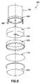
図6は、さらに別の例示的な自己発熱容器600のいくつかの構成要素を示す分解立体図である。
FIG. 6 is an exploded three-dimensional view showing some components of yet another exemplary self-
例示された実施形態において示された構成要素は、加熱される製品を保持するインナーカップ102と、粒状の第1の反応物質を包含する可溶性容器114と、液体の第2の反応物質を保持するための器634と、器634を密封するための脆い膜116と、例示された例において、下方へ面した鋸状の歯のある切縁を備えた環状リングである、脆い膜を破断するための手段とを含む。インナーカップ102の下部分に結合された駆動リング638がある。駆動リング638は、環状切断リング636に嵌合し、これを駆動するように構成されている複数の伸張部682を有する。
The components shown in the illustrated embodiments hold an
可溶性容器114の底面にはパッチ640がある。パッチ640は可溶性114における開口を覆い、液体の第2の反応物質に対して浸透性であり、粒状の第1の反応物質に対して実質的に不浸透性である。自己発熱容器600の操作中、パッチ640は大量の液体の第2の反応物質を別な方法より早く粒状の第1の反応物質に接近させることが可能である。典型的な実施形態において、これにより可溶性容器114が加熱開始前に溶解が必要な場合に生じるよりも迅速な加熱が発生する。
There is a
パッチ640は様々な可能な構成の任意の1つを有することができる。一例において、パッチ640は、液体を通すことを可能にするが、粒状材料の通過を妨げる孔径を有する多孔材料である。典型的に、パッチ640は、その意図された役割のために十分な物理的強度を有するべきである。さらに、その孔は粒状材料を保持するのに十分に小さくあるべきであり、液体反応物質によって容易に湿らされるべきである。普通のティーバッグにおいて使用されるもの等の材料が適しているかもしれない。パッチ640は、自己粘着リング又は熱融着によって可溶性容器114における穴の上に付着させることができる。パッチ及びその粘着リングが十分に小さく、反応物質の循環を阻止することがない限り、反応環境における不可溶物の潜在的な有害作用は最小になる。ティーバック状材料の使用の代案が、可溶性フィルムの1つの小さな領域(又は複数の小さな領域)に穴をあけ、行動開始と同時に液体材料の侵入を可能にすることであろう。
可溶性バッグにおける粒状材料は水分に敏感であり、相当の時間にわたって湿度に曝された場合は粘着してケークになることがある。これらのケークはいくぶん多孔性であり、液体の第2の反応物質と反応するが、最初は反応を遅らせるため起動が長引く。いくつかの実施形態において、自己発熱容器600は(例えば、アウターカップにおける)通気口を有し、これにより水分が反応空間内へ入るのが可能となる。微粒のケーク化の原因となり得る、この水分がパッチ640を通って粒状材料内へ侵入するのを防ぐには、パッチ640は、図6において示されているように、脆い膜に対して位置するように、可溶性容器の底上に配置することができる。可溶性容器114は通常、高度の柔軟性を備えたプラスチックフィルムであるため、脆い膜116に対してしっかりと押し付けることになる。この配置は水分の微粒内への侵入を効果的に防ぐ。
Granular materials in soluble bags are sensitive to moisture and can stick and become cake when exposed to humidity for a significant period of time. These cakes are somewhat porous and react with a second reactant in the liquid, but initially delay the reaction and thus prolong activation. In some embodiments, the self-
図7A及び図7Bは、さらに別の例示的な自己発熱容器700における液体の第2の反応物質を包含する器634上で脆いシール116を破断するための代替的な手段を示す。
7A and 7B show alternative means for breaking the
例示された実施形態は、脆い膜を破断するための手段に面する脆い膜116の上面に複数の突出部750を含む。これらの突出部750は様々な可能な材料から作ることができる。一例において、突出部は乾燥したグルードット(glue dots)である。
The illustrated embodiment comprises a plurality of
例示された実施形態における脆い膜を破断するための手段は、歯744を含むが、その各々は蝶番748によって複数の支持膜742の対応する1つに連結されている。各支持膜742はインナーカップ102にしっかりと結合されており(例えば、インナーカップ102の底部の上に押し付けられたリング746の構造物によって)、脆いシール116に向かって軸方向の下方に伸張する。例示された実施形態におけるインナーカップは(矢印Rで示されているように)旋回可能であるが、軸方向に大きく移動を受けることはない。各々の歯744は、インナーカップ102が回転しているとき、脆い膜116の上面に沿って、又はこれに極めて接近して滑動できるように配置されている。さらに、各歯はその支持膜の誘導面(すなわち、インナーカップ102が(矢印Rによって)示された方向に回転すると、移動を誘導する面)に結合され、脆い膜116の破断を引き起こす。最終的には、歯が突出部750の1つに達し、インナーカップ102が回転し続けると、歯は脆い膜の中へ及びこれを通ってその蝶番の周りを回転する。図7Bは、脆い膜116を通ってその蝶番を中心として枢動した後の例示的な歯の1つを示す。その点を越えるインナーカップ102のさらなる回転は、脆い膜116のさらなる引き裂きをもたらす。
Means for breaking the brittle membrane in the illustrated embodiment include
図8は、図2における自己発熱容器200と同様である自己発熱容器800の例示的な実施形態の部分断面側面図である。
FIG. 8 is a partial cross-sectional side view of an exemplary embodiment of the self-
図2の自己発熱容器200のように、図8の自己発熱容器800は、加熱される製品106を保持するインナーカップ102、及びインナーカップ102の少なくとも一部を取り囲むアウターカップ104と、インナー製品区画を密封するインナーカップ102の上部開放端における取り外し可能なカバー222と、発熱性化学反応に対応するインナーカップ102とアウターカップ104との間の空間108と、インナーカップ102の真下の可溶性容器(図8には示されていない)における第1の物質と、脆い膜116によって可溶性容器から物理的に分離される第2の物質と、脆い膜を破断するための手段と、自己発熱容器800の上周辺部縁における環状連結要素226と、密封要素232と、を有する。
Like the self-
本発明のいくつもの実施例を記載した。それにもかかわらず、本発明の精神及び範囲から逸脱することなく様々な変更がなされ得ることが理解されるであろう。 A number of examples of the present invention have been described. Nevertheless, it will be understood that various changes can be made without departing from the spirit and scope of the invention.
例えば、本明細書に記載の異なる実施形態からの異なる特徴をいくつもの方法で組み合わせることができる。同様に、本明細書に記載の実施形態のいくつかから一定の特徴を省略することができる。例えば、可溶材料及び/又は穿孔要素は、それらの要素の1つ以上を含む本明細書に記載の一定の実施形態から省略できる。さらに、様々な構成要素の相対的な大きさ及び位置決めには大きなばらつきがあり得る。例えば、可溶性容器における粒状反応物質は液体反応物質より下に位置することがあり得る。 For example, different features from different embodiments described herein can be combined in a number of ways. Similarly, certain features may be omitted from some of the embodiments described herein. For example, soluble materials and / or perforation elements can be omitted from certain embodiments described herein that include one or more of those elements. Moreover, there can be large variations in the relative size and positioning of the various components. For example, the granular reactant in a soluble container can be located below the liquid reactant.
自己発熱容器の実施形態の異なる成分を多種多様な異なる材料を用いて作ることができる。同様に、発熱反応を発生させる反応物質は異なる種類の反応物質であることができる。 Different components of the self-heating container embodiment can be made using a wide variety of different materials. Similarly, the reactants that cause an exothermic reaction can be different types of reactants.
一実施形態において、自己発熱容器の底は2つのプラスチックパウチを有する。この例における下部のパウチは化学反応の液体成分を包含するが、一方、水溶性である上部のパウチは、粒状(例えば、粉状、ペレット状等、固体)反応物質である第2の反応物質を包含する。いくつかの実施形態において、固体反応物質には被覆された過マンガン酸カリウムを含めることができ、液体成分(又は液体反応物質)にはグリセリンを含めることができる。これらの種類の剤形の例は、例えば、出願人のTempra Technology,Ins.自身の米国特許出願公開第2008/0245358号に記載されている。その他の反応物質及び反応物質の組み合わせも可能である。 In one embodiment, the bottom of the self-heating container has two plastic pouches. The lower pouch in this example contains the liquid component of the chemical reaction, while the upper pouch, which is water soluble, is a second reactant that is a granular (eg, powder, pellet, etc., solid) reactant. Including. In some embodiments, the solid reactant may include coated potassium permanganate and the liquid component (or liquid reactant) may include glycerin. Examples of these types of dosage forms include, for example, Applicant's Tempra Technology, Ins. It is described in Publication No. 2008/0245358 of his US patent application. Other reactants and combinations of reactants are also possible.
液体反応物質における溶媒は、水であることができ、又は事実上、任意の他の種類の溶媒であることができる。様々な添加物を反応物質の1つ以上と共に含めることができる。 The solvent in the liquid reactant can be water, or virtually any other type of solvent. Various additives can be included with one or more of the reactants.
さらに、典型的な実施形態において、自己発熱容器は、空気を容器のヒーター部分(例えば、反応空間)に抜けさせるベントシステムを含む。食物容器内に吸収されるよりも高い熱が反応中に発生する場合は、蒸気を発散させ、自己発熱容器における圧力上昇を防ぐことができる。 Further, in a typical embodiment, the self-heating vessel includes a vent system that allows air to escape to a heater portion (eg, reaction space) of the vessel. If higher heat is generated during the reaction than is absorbed in the food container, steam can be dissipated to prevent pressure rise in the self-heating container.
可溶材料は様々であり、その詳細は、出願人のTempra Technology,Ins.自身の米国特許出願公開第US20100239877号に開示され得る。 Soluble materials vary, the details of which are described in Applicant's Tempra Technology, Ins. It may be disclosed in US Patent Application Publication No. US201000239877.
最後に、本文書では、「下部の」、「上部の」、「水平の」、「鉛直の」、「より上に」、「より下に」、「上へ」、「下へ」、「上端」、及び「底」、並びにそれらの派生語(例えば、「水平に」、「下方への」、「上方への」等)等のいくつもの相対語が用いられる。一般に、これらの相対語、及びそれらの派生語は、論じられている特定の図面に示された方向づけを有する配置及び構成要素の物体及び相対位置を指すと理解されるべきである。別の方法で示されていない限り、相対用語は特定の方法で限定的と解釈されるべきではない。 Finally, in this document, "bottom", "top", "horizontal", "vertical", "above", "below", "above", "below", "down" A number of relative words are used, such as "top" and "bottom", as well as their derivatives (eg, "horizontally", "downward", "upward", etc.). In general, these relative terms, and their derivatives, should be understood to refer to the objects and relative positions of the arrangements and components with the orientations shown in the particular drawings being discussed. Relative terms should not be construed as limiting in any particular way, unless otherwise indicated.
他の実施形態は特許請求の範囲内にある。
Other embodiments are within the scope of the claims.
Claims (14)
前記粒状の第1の物質を包含する可溶性容器または可溶性バッグと、
前記可溶性容器または可溶性バッグから前記液体の第2の物質を物理的に分離する脆い膜と、
前記脆い膜を破断するための手段と、
加熱される製品を包含するインナーカップと、
アウターカップと、
前記インナーカップが前記アウターカップに対し同心軸の周りを回転すると前記インナーカップを前記アウターカップに対し軸方向の下方に移動させるように構成されたカム又はねじ山と、を備え、
前記インナーカップは、少なくとも部分的に前記アウターカップ内部にあり、
前記インナーカップは、前記アウターカップに対し前記同心軸の周りを回転するように構成されている、自己発熱容器。 A granular first substance and a liquid second substance that are adapted to cause an exothermic reaction when in contact with each other.
A soluble container or bag containing the granular first substance,
A brittle membrane that physically separates the second substance of the liquid from the soluble container or bag.
Means for breaking the brittle film and
An inner cup that contains the product to be heated and
Outer cup and
And a cam or a screw thread is configured to move in the axially downward relative to the outer cup the inner cup to rotate about said inner cup against the outer cup the mandrel,
The inner cup is at least partially inside the outer cup.
The inner cup is the relative outer cup is configured to rotate about the concentric shaft, self-heating container.
前記可溶性容器または可溶性バッグを溶解することは、前記液体の第2の物質が前記粒状の第1の物質に接触し、それによって前記発熱反応を発生させることを可能にする、請求項3に記載の自己発熱容器。 A second substance in the liquid that comes into contact with the soluble container or bag dissolves the soluble container or bag.
The third aspect of claim 3, wherein dissolving the soluble container or bag allows the second substance of the liquid to come into contact with the granular first substance, thereby causing the exothermic reaction. Self-heating container.
前記インナーカップの少なくとも一部を取り囲むアウターカップと、を備え、
前記粒状の第1の物質、前記液体の第2の物質、前記可溶性容器または可溶性バッグ、前記脆い膜、及び前記脆い膜を破断するための前記手段は、前記インナーカップと前記アウターカップとの間の空間に位置しており、且つ
前記発熱反応は前記インナーカップと前記アウターカップとの間の前記空間において生じる、請求項1に記載の自己発熱容器。 In addition, with an inner cup configured to hold the product to be heated,
An outer cup that surrounds at least a part of the inner cup is provided.
The granular first substance, the liquid second substance, the soluble container or bag, the brittle film, and the means for breaking the brittle film are between the inner cup and the outer cup. The self-heating container according to claim 1, wherein the exothermic reaction occurs in the space between the inner cup and the outer cup.
前記インナーカップが前記アウターカップに対し前記同心軸の周りを回転して前記アウターカップに対し前記軸方向の下方に移動すると、前記脆い膜を破断するための前記手段が、前記同心軸の周りを回転して前記脆い膜に向かって且つこれを通って軸方向の下方に移動するように、
前記インナーカップに連結されている、請求項1に記載の自己発熱容器。 The means for breaking the brittle membrane is
When the inner cup rotates about the concentric shaft with respect to the outer cup and moves downward in the axial direction with respect to the outer cup, the means for breaking the brittle film moves around the concentric shaft. As it rotates toward and through the brittle membrane, it moves downward in the axial direction.
The self-heating container according to claim 1, which is connected to the inner cup.
前記脆い膜を破断するための前記手段が前記脆い膜を通って移動した後、前記インナーカップの前記アウターカップに対する前記同心軸の周りの継続的な回転が前記インナーカップに前記可溶性容器または可溶性バッグを前記第2の物質内へ押させるように、
構成されている、請求項7に記載の自己発熱容器。 The inner cup
After the means for breaking the brittle membrane has moved through the brittle membrane, continuous rotation of the inner cup around the concentric axis with respect to the outer cup causes the inner cup to have the soluble container or bag. To push into the second substance
The self-heating container according to claim 7, which is configured.
前記インナーカップは、前記脆い膜を破断するための前記手段が前記脆い膜を通って移動した後、前記インナーカップの前記アウターカップに対する前記同心軸の周りの継続的な回転が、前記インナーカップの前記アウターカップに対するさらなる軸方向の下方への移動を引き起こし、前記可溶性容器または可溶性バッグを前記穿孔要素の上に押すように、
構成されている、請求項7に記載の自己発熱容器。 In addition, it has a perforation element,
In the inner cup, after the means for breaking the brittle film has moved through the brittle film, continuous rotation of the inner cup around the concentric axis with respect to the outer cup of the inner cup. To cause further axial downward movement with respect to the outer cup and push the soluble container or bag over the perforated element.
The self-heating container according to claim 7, which is configured.
互いに接触すると発熱反応を発生させるように適合されている粒状の第1の物質及び液体の第2の物質と、
前記粒状の第1の物質を包含する可溶性容器または可溶性バッグと、
前記可溶性容器または可溶性バッグから前記液体の第2の物質を物理的に分離する脆い膜と、
前記脆い膜を破断するための手段と、
加熱される製品を包含するインナーカップと、
アウターカップと、を備え、
前記インナーカップは、少なくとも部分的に前記アウターカップ内部にあり、
前記インナーカップは、前記アウターカップに対し軸方向に実質的に移動することなく、前記アウターカップに対し同心軸の周りを回転することができ、
前記自己発熱容器は、さらに、
前記インナーカップが前記アウターカップに対し前記同心軸の周りを回転すると、前記脆い膜を破断するための前記手段を前記脆い膜に向かって、且つこれを通って軸方向に移動させるように構成されたカム又はねじ山を備える、自己発熱容器。 It is a self-heating container
A granular first substance and a liquid second substance that are adapted to cause an exothermic reaction when in contact with each other.
A soluble container or bag containing the granular first substance,
A brittle membrane that physically separates the second substance of the liquid from the soluble container or bag.
Means for breaking the brittle film and
An inner cup that contains the product to be heated,
With an outer cup,
The inner cup is at least partially inside the outer cup.
The inner cup can rotate about a concentric axis with respect to the outer cup without substantially moving axially with respect to the outer cup.
The self-heating container further
When the inner cup rotates about the concentric shaft with respect to the outer cup, the means for breaking the brittle film is configured to move axially toward and through the brittle film. A self-heating container with a cam or thread.
前記金具は、前記脆い膜を破断するための前記手段が前記軸方向の下方に移動すると、当該金具も前記軸方向の下方に移動して前記可溶性容器を前記第2の物質へ向かって押すように配置されている、請求項10に記載の自己発熱容器。 A metal fitting coupled to the means for breaking the brittle film.
When the means for breaking the brittle film moves downward in the axial direction, the metal fitting also moves downward in the axial direction and pushes the soluble container toward the second substance. The self-heating container according to claim 10, which is arranged in.
前記金具は、
前記脆い膜を破断するための前記手段が前記脆い膜を破断させた後、前記インナーカップの前記アウターカップに対する前記同心軸の周りの継続的な回転が、前記アウターカップに対する前記金具のさらなる軸方向の下方への移動をもたらし、前記可溶性容器または可溶性バッグを前記穿孔要素の上に押すように、
構成されている、請求項11に記載の自己発熱容器。 In addition, it has a perforation element,
The metal fittings
After the means for breaking the brittle film breaks the brittle film, the continuous rotation of the inner cup around the concentric axis with respect to the outer cup is further axial to the metal fitting with respect to the outer cup. To bring the downward movement of the soluble container or bag to push onto the perforated element,
The self-heating container according to claim 11, which is configured.
自己発熱容器を提供することであって、前記自己発熱容器は、
互いに接触すると発熱反応を発生させるように適合されている粒状の第1の物質及び液体の第2の物質と、
前記第1の物質を包含する可溶性容器または可溶性バッグと、
前記可溶性容器または可溶性バッグから前記液体の第2の物質を物理的に分離する脆い膜と、
前記脆い膜を破断するための手段と、
加熱される製品を包含するインナーカップと、
アウターカップと、を備え、
前記インナーカップは、少なくとも部分的に前記アウターカップ内部にあり、
前記インナーカップは、前記アウターカップに対し同心軸の周りを回転するように構成されている、自己発熱容器を提供することと、
前記脆い膜を破断することと、
を含み、
前記自己発熱容器は、
前記インナーカップが前記アウターカップに対し前記同心軸の周りを回転すると前記インナーカップを前記アウターカップに対し軸方向の下方に移動させるように構成されたカム又はねじ山、あるいは
前記インナーカップが前記アウターカップに対し前記同心軸の周りを回転すると、前記脆い膜を破断するための前記手段を前記脆い膜に向かって、且つこれを通って軸方向に移動させるように構成されたカム又はねじ山
を有する、方法。
In the method of heating the product
To provide a self-heating container, the self-heating container is
A granular first substance and a liquid second substance that are adapted to cause an exothermic reaction when in contact with each other.
A soluble container or bag containing the first substance,
A brittle membrane that physically separates the second substance of the liquid from the soluble container or bag.
Means for breaking the brittle film and
An inner cup that contains the product to be heated and
With an outer cup,
The inner cup is at least partially inside the outer cup.
The inner cup provides a self-heating container that is configured to rotate about a concentric axis with respect to the outer cup.
Breaking the brittle film and
Including
The self-heating container is
A cam or thread configured to move the inner cup axially downward with respect to the outer cup when the inner cup rotates about the concentric shaft with respect to the outer cup, or the inner cup is the outer. A cam or thread configured to rotate around the concentric shaft with respect to the cup to move the means for breaking the brittle film toward and axially through the brittle film. How to have.
Applications Claiming Priority (3)
| Application Number | Priority Date | Filing Date | Title |
|---|---|---|---|
| US201461992422P | 2014-05-13 | 2014-05-13 | |
| US61/992,422 | 2014-05-13 | ||
| PCT/US2015/030077 WO2015175371A1 (en) | 2014-05-13 | 2015-05-11 | Product heating with soluble container |
Publications (3)
| Publication Number | Publication Date |
|---|---|
| JP2017515756A JP2017515756A (en) | 2017-06-15 |
| JP2017515756A5 JP2017515756A5 (en) | 2018-06-28 |
| JP6817815B2 true JP6817815B2 (en) | 2021-01-20 |
Family
ID=54480485
Family Applications (1)
| Application Number | Title | Priority Date | Filing Date |
|---|---|---|---|
| JP2016565042A Active JP6817815B2 (en) | 2014-05-13 | 2015-05-11 | Heating the product in a soluble container |
Country Status (8)
| Country | Link |
|---|---|
| US (2) | US10850911B2 (en) |
| EP (1) | EP3142943B1 (en) |
| JP (1) | JP6817815B2 (en) |
| CN (1) | CN107074430B (en) |
| CY (1) | CY1122032T1 (en) |
| ES (1) | ES2745536T3 (en) |
| TW (1) | TW201600054A (en) |
| WO (1) | WO2015175371A1 (en) |
Families Citing this family (10)
| Publication number | Priority date | Publication date | Assignee | Title |
|---|---|---|---|---|
| IL252764A0 (en) * | 2017-06-07 | 2017-08-31 | Novamed Ltd | Puncturing element for gradual liquid flow |
| CN107264995A (en) * | 2017-06-17 | 2017-10-20 | 常州朋悦纺织品有限公司 | Type food self-heating apparatus and its application process can be recycled in one kind |
| EP3982058A1 (en) * | 2017-07-20 | 2022-04-13 | Tempra Technology, Inc. | Self-heating food pouch with distributed reactants and method of manufacturing |
| FR3069146A1 (en) * | 2017-07-20 | 2019-01-25 | C.G.L. Pack Service | SELF-HEATING CONTAINER |
| CN108784396B (en) * | 2018-05-10 | 2021-07-16 | 王清妍 | Portable automatic heating device and application thereof |
| CN109703915A (en) * | 2019-03-05 | 2019-05-03 | 广州九润医药科技有限公司 | A kind of facial mask of self-heating |
| JOP20220103A1 (en) * | 2019-10-30 | 2023-01-30 | Tempra Tech Inc | Sealed package for solid reactant in self-heating assembly |
| ES2850526B2 (en) * | 2020-02-28 | 2022-03-07 | Univ Del Pais Vasco / Euskal Herriko Unibertsitatea | DEVICE AND ASSEMBLY FOR HEATING FLUID CONTAINER, AND METHOD FOR HEATING FLUID |
| CN115605410A (en) * | 2020-03-12 | 2023-01-13 | 坦普拉科技股份有限公司(Us) | Actuator for self-heating container |
| CN112890571B (en) * | 2021-02-05 | 2021-12-17 | 长沙理工大学 | Self-heating chafing dish with scald preventing structure |
Family Cites Families (29)
| Publication number | Priority date | Publication date | Assignee | Title |
|---|---|---|---|---|
| US2300793A (en) * | 1941-03-22 | 1942-11-03 | Virgil E C Martin | Self-heating can |
| US3561424A (en) * | 1969-09-15 | 1971-02-09 | Anthony C Failla | Food warming by exothermic reaction |
| US3970068A (en) * | 1973-05-29 | 1976-07-20 | Shotaro Sato | Heat exchange package for food |
| US4306556A (en) * | 1980-02-07 | 1981-12-22 | Rensselaer Polytechnic Institute | Method and apparatus for storing and preparing cryopreserved blood |
| JPS61253023A (en) | 1985-04-04 | 1986-11-10 | 旭化成株式会社 | Heating container |
| JPS62135172A (en) | 1985-11-27 | 1987-06-18 | 凸版印刷株式会社 | Heat-generating vessel |
| FR2598070B1 (en) * | 1986-05-05 | 1989-05-19 | Labrousse Bernard | SINGLE USE HEAT TRANSFER PACKAGING FOR BEVERAGES, FOODS AND MEDICINES |
| JPH01213179A (en) | 1988-02-16 | 1989-08-25 | Dainippon Printing Co Ltd | Container for heating foodstuffs |
| CN2124206U (en) | 1992-03-19 | 1992-12-09 | 黄文城 | Automatic heating can |
| JPH06271842A (en) | 1993-03-23 | 1994-09-27 | Sadamu Hoshi | Exothermic body and its constituting component |
| CN2178700Y (en) | 1993-10-21 | 1994-10-05 | 徐欣 | Disposable drinking container with automatic-heating sealing |
| US5388565A (en) * | 1994-04-01 | 1995-02-14 | Ou; Lih-Horng | Self-heating container system |
| CA2152452C (en) | 1995-06-22 | 1998-02-03 | Robert Freiman | Self heating container |
| US6116231A (en) * | 1998-02-11 | 2000-09-12 | Tempra Technology, Inc. | Liquid heat pack |
| US6079405A (en) * | 1999-11-30 | 2000-06-27 | Justo; Jose A. | Container with in situ dual food product mixing and heating |
| CN2450142Y (en) | 2000-09-28 | 2001-09-26 | 上海华东食品饮料工业研究所 | Self-heated beverage can |
| US6481470B1 (en) | 2002-07-03 | 2002-11-19 | John Rubenic | Aerosol can and contents salvage apparatus |
| US7912749B2 (en) * | 2003-07-11 | 2011-03-22 | Computer Associates Think, Inc. | Infrastructure auto discovery from business process models via middleware flows |
| DE102004003998A1 (en) | 2004-01-26 | 2005-09-01 | Winter, Michael, Dr. | Pre-pack for preparing hot food and drinks |
| JP4556534B2 (en) | 2004-08-02 | 2010-10-06 | 富士ゼロックス株式会社 | Recording medium and hologram reading apparatus |
| US7722782B2 (en) | 2005-07-12 | 2010-05-25 | Rechargeable Battery Corporation | Portable heating apparatus and metal fuel composite for use with same |
| WO2007042176A1 (en) | 2005-10-11 | 2007-04-19 | Smart Holograms Ltd. | Interactive holographic security element |
| US20080000898A1 (en) * | 2006-06-28 | 2008-01-03 | Christopher Edward Ramsden | Methods and apparatus for providing edible substances with a beverage |
| WO2008058062A2 (en) * | 2006-11-07 | 2008-05-15 | Tempra Technology, Inc. | Method for adding a fusible material to a container wall |
| WO2010059636A2 (en) * | 2008-11-18 | 2010-05-27 | Tempra Technology, Inc. | Self-heating container with activation mechanism |
| US8101133B2 (en) * | 2010-02-25 | 2012-01-24 | Praxair Technology, Inc. | Radial flow reactor |
| US20120193367A1 (en) * | 2011-01-27 | 2012-08-02 | Silgan Containers Llc | Heated container having chemical heating mechanism |
| CN103287735A (en) | 2013-05-08 | 2013-09-11 | 谭军 | Can with automatic temperature control function |
| US20140358206A1 (en) * | 2013-05-31 | 2014-12-04 | Laurie HIROKANE | Therapeutic heating and cooling packs comprising decorative elements |
-
2015
- 2015-05-11 US US15/309,823 patent/US10850911B2/en active Active
- 2015-05-11 EP EP15792228.7A patent/EP3142943B1/en active Active
- 2015-05-11 WO PCT/US2015/030077 patent/WO2015175371A1/en active Application Filing
- 2015-05-11 JP JP2016565042A patent/JP6817815B2/en active Active
- 2015-05-11 CN CN201580036869.4A patent/CN107074430B/en active Active
- 2015-05-11 ES ES15792228T patent/ES2745536T3/en active Active
- 2015-05-13 TW TW104115207A patent/TW201600054A/en unknown
-
2019
- 2019-09-16 CY CY20191100962T patent/CY1122032T1/en unknown
-
2020
- 2020-10-27 US US17/080,996 patent/US11905099B2/en active Active
Also Published As
| Publication number | Publication date |
|---|---|
| CY1122032T1 (en) | 2020-10-14 |
| US20170267437A1 (en) | 2017-09-21 |
| TW201600054A (en) | 2016-01-01 |
| US20210039868A1 (en) | 2021-02-11 |
| WO2015175371A1 (en) | 2015-11-19 |
| US11905099B2 (en) | 2024-02-20 |
| JP2017515756A (en) | 2017-06-15 |
| US10850911B2 (en) | 2020-12-01 |
| EP3142943B1 (en) | 2019-06-19 |
| EP3142943A4 (en) | 2017-11-29 |
| EP3142943A1 (en) | 2017-03-22 |
| ES2745536T3 (en) | 2020-03-02 |
| CN107074430B (en) | 2019-10-29 |
| CN107074430A (en) | 2017-08-18 |
Similar Documents
| Publication | Publication Date | Title |
|---|---|---|
| JP6817815B2 (en) | Heating the product in a soluble container | |
| JP6078679B2 (en) | Instant self-heating dispenser | |
| CA2700303C (en) | Self-heating apparatuses using solid chemical reactants | |
| EP1481921A1 (en) | Autothermic packaging | |
| US9360233B2 (en) | Heated container having chemical heating mechanism | |
| EP2911950B1 (en) | Temperature changing container | |
| CA3019390C (en) | Self-heating assembly with distributed reactant | |
| US11484149B2 (en) | Shrink film container for self-heating assembly | |
| US11661261B2 (en) | Self-contained meal assembly with steam vent | |
| US11747050B2 (en) | Sealed package for solid reactant in self-heating assembly | |
| MX2009001240A (en) | Two part vessel with a hingeable actuator for a cutter. | |
| JPH0523162Y2 (en) | ||
| KR20170135286A (en) | Fever container with a Damage mechanism | |
| RU2004126255A (en) | SELF-HEATING PACKAGING |
Legal Events
| Date | Code | Title | Description |
|---|---|---|---|
| A621 | Written request for application examination |
Free format text: JAPANESE INTERMEDIATE CODE: A621 Effective date: 20180510 |
|
| A521 | Request for written amendment filed |
Free format text: JAPANESE INTERMEDIATE CODE: A523 Effective date: 20180515 |
|
| A621 | Written request for application examination |
Free format text: JAPANESE INTERMEDIATE CODE: A621 Effective date: 20180510 |
|
| A977 | Report on retrieval |
Free format text: JAPANESE INTERMEDIATE CODE: A971007 Effective date: 20190409 |
|
| A131 | Notification of reasons for refusal |
Free format text: JAPANESE INTERMEDIATE CODE: A131 Effective date: 20190527 |
|
| A521 | Request for written amendment filed |
Free format text: JAPANESE INTERMEDIATE CODE: A523 Effective date: 20190823 |
|
| A131 | Notification of reasons for refusal |
Free format text: JAPANESE INTERMEDIATE CODE: A131 Effective date: 20191202 |
|
| A601 | Written request for extension of time |
Free format text: JAPANESE INTERMEDIATE CODE: A601 Effective date: 20200212 |
|
| A521 | Request for written amendment filed |
Free format text: JAPANESE INTERMEDIATE CODE: A523 Effective date: 20200430 |
|
| A131 | Notification of reasons for refusal |
Free format text: JAPANESE INTERMEDIATE CODE: A131 Effective date: 20200720 |
|
| A521 | Request for written amendment filed |
Free format text: JAPANESE INTERMEDIATE CODE: A523 Effective date: 20200924 |
|
| TRDD | Decision of grant or rejection written | ||
| A01 | Written decision to grant a patent or to grant a registration (utility model) |
Free format text: JAPANESE INTERMEDIATE CODE: A01 Effective date: 20201201 |
|
| A61 | First payment of annual fees (during grant procedure) |
Free format text: JAPANESE INTERMEDIATE CODE: A61 Effective date: 20201225 |
|
| R150 | Certificate of patent or registration of utility model |
Ref document number: 6817815 Country of ref document: JP Free format text: JAPANESE INTERMEDIATE CODE: R150 |
|
| R250 | Receipt of annual fees |
Free format text: JAPANESE INTERMEDIATE CODE: R250 |