JP6814618B2 - Quick connection terminal of outlet - Google Patents
Quick connection terminal of outlet Download PDFInfo
- Publication number
- JP6814618B2 JP6814618B2 JP2016236952A JP2016236952A JP6814618B2 JP 6814618 B2 JP6814618 B2 JP 6814618B2 JP 2016236952 A JP2016236952 A JP 2016236952A JP 2016236952 A JP2016236952 A JP 2016236952A JP 6814618 B2 JP6814618 B2 JP 6814618B2
- Authority
- JP
- Japan
- Prior art keywords
- electric wire
- piece
- wire
- quick
- housing
- Prior art date
- Legal status (The legal status is an assumption and is not a legal conclusion. Google has not performed a legal analysis and makes no representation as to the accuracy of the status listed.)
- Active
Links
Images


Description
本発明は、壁面等に設置されるコンセントに対して電線を接続するため速結端子に関する。 The present invention relates to a quick connection terminal for connecting an electric wire to an outlet installed on a wall surface or the like.
主に壁面に設置されるコンセントでは、電線の接続に速結端子が使用されている。速結端子は、電線を差し込むだけで電気的接続を図ることができ、ネジ止め等しなくても抜けることがないので、簡易な操作で接続でき普及している。この速結端子は、引き抜くためのリリースボタンが設けられており、このボタンを操作して、速結端子の電線抜け止め作用を解除して電線を引き抜いた。 In outlets that are mainly installed on the wall, quick-connect terminals are used to connect electric wires. The quick-connect terminal can be electrically connected by simply inserting an electric wire, and does not come off without screwing, so it can be connected with a simple operation and is widely used. This quick-connect terminal is provided with a release button for pulling out, and by operating this button, the wire disconnection prevention action of the quick-connect terminal was released and the wire was pulled out.
図5はこの従来の速結端子の一例を模式的に示している。図5に示すように、リリースボタン50は電線を挿入する挿入孔51に隣接して配置され、このリリースボタン50を矢印A3に示す方向に傾倒操作することで、速結バネ52の電線53への係止を解除させて、電線53の引き抜きを可能とした。
例えば特許文献1では、速結端子近くのハウジング内部にリリースボタンが配置され、ハウジングに形成された窓からドライバー等で操作する構成が開示されている。
FIG. 5 schematically shows an example of this conventional quick-connect terminal. As shown in FIG. 5, the
For example,
コンセントに設けられている上記従来の速結端子は、図5ではリリースボタン50を誇張して記載しているが、特許文献1に開示されているように、僅かなスペースに設けられており、操作部が小さいし解除操作する荷重も重く、操作性が悪かった。
また、挿入された電線が確実に速結バネ52に接続されているか表示する部材が無く、電線の接続確認はテスター等で確認するしかなかった。
The conventional quick-connect terminal provided in the outlet is described by exaggerating the
In addition, there is no member to indicate whether the inserted electric wire is securely connected to the quick-connect
そこで、本発明はこのような問題点に鑑み、接続された電線のリリース操作を比較的弱い力で行うことができ、また差し込まれた電線が速結バネに接続されていることを表示する差込表示部を省スペースで設けたコンセントの速結端子を提供することを目的としている。 Therefore, in view of such a problem, the present invention can perform the release operation of the connected electric wire with a relatively weak force, and also indicates that the inserted electric wire is connected to the quick-connect spring. The purpose is to provide a quick-connect terminal for an outlet with an embedded display in a space-saving manner.
上記課題を解決する為に、請求項1の発明は、ハウジングに形成された挿入孔から挿入された電線をコンセント刃受けに電気的に接続するためのハウジング内に形成されたコンセントの速結端子であって、挿入された電線に弾性接触する連結部と、連結部の挿入孔側で電線挿入方向に傾倒し、挿入された電線に傾倒した先端が係止して電線の抜け止めを図る抜け止め片とを有し、略S字状に折り曲げ形成されてコンセント刃受けに電気的に接続された速結バネと、抜け止め片の電線への係止作用を解除する係止解除部材とを有し、係止解除部材は、挿入孔に隣接する部位に突出配置されたリリースボタンと、当該リリースボタンの背部に連続形成されて、電線挿入方向に延設されてハウジング内を摺動する摺動部と、摺動部の側部に形成されて、抜け止め片に当接する解除片とを有し、リリースボタンが押し込み操作されて、摺動部が摺動してハウジングの内部へ移動すると、解除片が抜け止め片を更に傾倒させて電線係止作用を解除し、電線の引き抜きが可能となることを特徴とする。
この構成によれば、挿入された電線の抜け止めを解除する操作は、抜け止め片を電線挿入方向へ押すため、押し込み量に応じて抜け止め片の先端寄りに力点が移動する。よって、軽い荷重即ち弱い押し込み力でリリース操作できる。
In order to solve the above problem, the invention of
According to this configuration, the operation of releasing the retaining piece of the inserted electric wire pushes the retaining piece in the wire insertion direction, so that the point of effort moves toward the tip of the retaining piece according to the pushing amount. Therefore, the release operation can be performed with a light load, that is, a weak pushing force.
請求項2の発明は、請求項1に記載の構成において、速結端子に電線が確実に接続されたことを表示するための表示部材を有し、表示部材は、リリースボタンに隣接する部位でハウジングから露出した差込表示部を先端に有して、差込表示部の背部から電線挿入方向に延設されて、連結部を越える位置に至る長さを有する連結片と、連結片の延設した端部から折り曲げ形成されて、挿入孔の底部に配置されて挿入された電線の先端が当接する電線当接片とを有する一方、電線当接片の背部には、電線当接片がハウジングの内部方向への移動を可能とする隙間を有して、挿入された電線の先端が電線当接片を押圧してハウジングの内部へ移動させることで、差込表示部の露出量が変化し、この変化で電線の挿入完了を把握できることを特徴とする。
この構成によれば、表示部材は連結片と電線当接片とを例えばL字状に形成でき、然も薄い部材で作製可能であるため、僅かなスペースに組み込むことが可能となる。よって、設置スペースが小さいコンセントの速結端子であっても、無理なく組み込むことができ、挿入された電線が速結バネに接続されていることを把握できる。
The invention of
According to this configuration, the display member can form the connecting piece and the electric wire contact piece in an L shape, for example, and can be manufactured with a thin member, so that the display member can be incorporated in a small space. Therefore, even a quick-connect terminal of an outlet with a small installation space can be easily incorporated, and it can be grasped that the inserted electric wire is connected to the quick-connect spring.
本発明によれば、挿入された電線の抜け止めを解除するリリースボタン操作は、抜け止め片を電線挿入方向へ押すため、押し込み量に応じて抜け止め片の先端寄りに力点が移動する。よって、軽い荷重即ち弱い押し込み力でリリース操作できる。 According to the present invention, the release button operation for releasing the retaining piece of the inserted electric wire pushes the retaining piece in the wire insertion direction, so that the force point moves toward the tip of the retaining piece according to the pushing amount. Therefore, the release operation can be performed with a light load, that is, a weak pushing force.
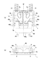
以下、本発明を具体化した実施の形態を、図面を参照して詳細に説明する。図1は本発明に係るコンセントの速結端子の一例を示す断面説明図であり、1はコンセントのハウジング、2は電線11を挿入する挿入孔、3は挿入された電線11と図示しないコンセント刃受けとを電気的に接続させる速結バネ、4は電線11の引き抜きを可能とするリリースボタン4aを備えた係止解除部材、5aは電線11の差し込み状態を表示する差込表示部であり、速結端子10はコンセントのハウジング1の内部に形成されている。
尚、7はコンセント刃受けに連結されている端子金具であり、速結バネ3と接触状態にある。また、挿入孔2の形成面をハウジング1の前面として以下説明する。
Hereinafter, embodiments embodying the present invention will be described in detail with reference to the drawings. FIG. 1 is a cross-sectional explanatory view showing an example of a quick-connect terminal of an outlet according to the present invention, where 1 is an outlet housing, 2 is an insertion hole into which an
速結バネ3は帯状金属片を略S字状に折り曲げて形成した弾性を有するバネ片であり、挿入された電線と電気的接続を図るために曲面で形成された連結部3aと、挿入された電線の抜けを防止するために金属片の端部で形成された抜け止め片3bとを有し、抜け止め片3bを挿入孔2側に配置し、連結部3aをハウジング1の奥部に配置している。
抜け止め片3bは、ハウジング1の前面近くから矢印A1で示す電線挿入方向に折り曲げられて傾倒配置され、先端は連結部3aの近傍に配置されている。
The quick-connecting
The
リリースボタン4aは、挿入孔2に隣接して配置された係止解除部材4の先端部であり、ハウジング1から突出している。係止解除部材4は、リリースボタン4aの背部に連続形成されて、電線挿入方向(矢印A1の方向)に摺動可能にハウジング1内に配置された摺動部4bを有し、この摺動部4bの側部に抜け止め片に当接する解除片4cが突設されている。
そして、摺動部4bとハウジング1との間には、摺動部4bを前方に付勢するコイルバネ20が配置され、リリースボタン4aが押下されて摺動部4bがハウジング1内へ摺動しても、復帰動作するよう構成されている。
The
A
解除片4cは、摺動部4bの側部から速結バネ3方向に突出形成され、途中挿入された電線11が接触しないよう迂回する形状を成して、先端は抜け止め片3bの途中に当接している。この解除片4cは、リリースボタン4aが押し込み操作を受けると、傾倒配置されている抜け止め片3bを更に傾倒させ、抜け止め片3bの電線11への係止を解除させる。
The
差込表示部5aは、リリースボタン4aに隣接して配置された表示部材5のハウジング1から露出した先端部であり、表示部材5は電線挿入方向に延設された連結片5bと、挿入された電線11の先端が当接する電線当接片5cを有している。連結片5bは、速結バネ3の連結部3aを越える位置に至る長さを有し、電線当接片5cは連結片5bの端部から横方向に延びて挿入孔2の底部に至る長さを有している。結果、表示部材5は全体で略L字状に形成されている。
The
また、電線当接片5cの背部には、電線当接片5cがハウジング1の内部方向への移動を可能とする、即ち表示部材5のハウジング1の内部への移動を可能とする隙間Sが設けられている。そして、電線当接片5cの背部には表示部材5を前方へ常時付勢するコイルバネ21が配置されている。
こうして速結端子10は、ハウジング1の挿入孔2の一方の側に速結バネ3が配置され、他方の側にリリースボタン4a、差込表示部5aの順に配置され、表面上は一直線に並べて配置されている。
Further, on the back of the electric
In this way, in the quick-connect
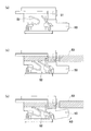
図2はこの速結端子10に電線11を挿入した説明図であり、(a)は電線11が係止されている状態、(b)は係止が解除された状態を示している。
図2(a)に示すように、挿入孔2から挿入された電線11は、速結バネ3に接触係合した後、挿入孔2の底部にある電線当接片5cに当接し、更に電線当接片5cを押し込んで挿入完了となる。こうして電線当接片5cは、当接した電線11の押圧力で隙間Sの奥に移動し、差込表示部5aの突出量が減少し僅かとなる。
また、挿入された電線11により速結バネ3は弾性変形し、その復元力で連結部3aが電線11に密着して弾性接触状態を維持するし、電線当接片3bは抜け止め作用を発揮する。
2A and 2B are explanatory views in which the
As shown in FIG. 2A, the
Further, the quick-connecting
この状態で、リリースボタン4aが押下されると、図2(b)に示すように、解除片4cが抜け止め片3bを更に折り曲げるため、電線11への係止作用が解除され、電線11の引き抜きが可能となる。その際、リリースボタン4aを押し込むに従い、解除片4cの抜け止め片3bへの係合点が先端寄りに移動する。
こうして係止が解除された状態で電線11を抜き取ると、表示部材5がコイルバネ21の作用で元の位置に復帰し、差込表示部5aが突出する或いは突出量が増加する。また、リリースボタン4aも、押下が解除されるとコイルバネ20の作用で元の位置に復帰する。
When the
When the
このように、挿入された電線11の抜け止めを解除する操作は、抜け止め片3bを電線挿入方向へ押すため、押し込み量に応じて抜け止め片3bの先端寄りに力点が移動する。よって、軽い荷重即ち弱い押し込み力でリリース操作できる。
また、表示部材5はL字状に長いが薄い板材で形成でき、僅かなスペースに組み込むことが可能であり、設置スペースの少ないコンセントの速結端子であっても、無理なく組み込むことができ、電線11が速結バネ3に接続されていることを把握できる。
In this way, the operation of releasing the retaining
Further, the
図3,4は、コンセントの速結端子の他の例を示す説明図であり、2つの速結端子10,10を1つのリリースボタン40aで操作する構成を示している。図3は電線挿入前の状態、図4はリリースボタン40aを押下して挿入した電線11を引き抜き可能とした状態を示し、いずれも(a)は断面説明図、(b)は正面説明図である。
図示するように、2つの速結端子10、10が対称線Mを中心に互いに対称配置され、速結バネ3が背中合わせ状態で配置されている。そして、リリースボタン40aが一体に形成されている。
3 and 4 are explanatory views showing another example of the quick-connect terminal of the outlet, and show a configuration in which the two quick-
As shown in the figure, the two quick-connecting
以下、速結バネ3、表示部材5は上記形態と同様であるため説明を省略し、リリースボタン40aについて説明する。
リリースボタン40aは、2つの挿入孔2,2に跨がる幅を有して形成され、このリリースボタン40aの背部には、挿入孔2の位置に合わせて配置された一対の摺動部40bを有する係止解除部材40が形成されている。
Hereinafter, since the quick-connecting
The
摺動部40bは、矢印A2で示す電線挿入方向であるハウジング1の内部に向けて形成され、後端側部に抜け止め片3bに当接する解除片40cが形成されている。結果、係止解除部材40全体は略コ字状に形成されている。
そして、リリースボタン40aを押下すると、解除片40cが抜け止め片3bを更に折り曲げるため、電線11への係止作用が解除され、電線11の引き抜きが可能となる。
尚、上記形態と同様に、リリースボタン40aにも常時前方に付勢するコイルバネがハウジング1との間に設けられているが省略してある。
The sliding
Then, when the
Similar to the above embodiment, the
このように、2つの速結端子を対称に配置すれば、リリースボタン40aを省スペースで一体にでき、設置スペースを更に削減できる。また、差込表示部5aも省スペースで設けることができる。そして、挿入された電線11の抜け止めを解除する操作は、抜け止め片3bを電線挿入方向へ押すため、押し込み量に応じて抜け止め片3bの先端寄りに力点が移動するため、軽い荷重即ち弱い押し込み力でリリース操作できる。
By arranging the two quick-connect terminals symmetrically in this way, the
尚、上記実施形態は、何れも電線11が確実に接続されたことを表示するための表示部材5を設けているが、この表示部材5は無くても良い。
In each of the above embodiments, a
1・・ハウジング、2・・挿入孔、3・・速結バネ、3a・・連結部、3b・・抜け止め片、4・・係止解除部材、4a・・リリースボタン、4b・・摺動部、4c・・解除片、5・・表 示部材、5a・・差込表示部、5b・・連結部、5c・・電線当接片、10・・速結端子、11・・電線、20,21・・コイルバネ、40・・係止解除部材、40a・・リリースボタン、40b・・摺動部、40c・・解除片。 1 ・ ・ Housing, 2 ・ ・ Insert hole, 3 ・ ・ Quick connection spring, 3a ・ ・ Connecting part, 3b ・ ・ Retaining piece, 4 ・ ・ Unlocking member, 4a ・ ・ Release button, 4b ・ ・ Sliding , 4c ... Release piece, 5 ... Display member, 5a ... Plug-in display part, 5b ... Connecting part, 5c ... Wire contact piece, 10 ... Quick connection terminal, 11 ... Wire, 20 , 21 ... Coil spring, 40 ... Unlocking member, 40a ... Release button, 40b ... Sliding part, 40c ... Release piece.
Claims (2)
挿入された電線に弾性接触する連結部と、前記連結部の前記挿入孔側で電線挿入方向に傾倒し、挿入された電線に傾倒した先端が係止して電線の抜け止めを図る抜け止め片とを有し、略S字状に折り曲げ形成されて前記コンセント刃受けに電気的に接続された速結バネと、
前記抜け止め片の電線への係止作用を解除する係止解除部材とを有し、
前記係止解除部材は、前記挿入孔に隣接する部位に突出配置されたリリースボタンと、
当該リリースボタンの背部に連続形成されて、電線挿入方向に延設されて前記ハウジング内を摺動する摺動部と、
前記摺動部の側部に形成されて、前記抜け止め片に当接する解除片とを有し、
前記リリースボタンが押し込み操作されて、前記摺動部が摺動して前記ハウジングの内部へ移動すると、前記解除片が前記抜け止め片を更に傾倒させて電線係止作用を解除し、電線の引き抜きが可能となることを特徴とするコンセントの速結端子。 A quick-connect terminal for an outlet formed in the housing for electrically connecting an electric wire inserted through an insertion hole formed in the housing to an outlet blade holder.
A retaining piece that elastically contacts the inserted electric wire and tilts in the wire insertion direction on the insertion hole side of the connecting portion and locks the tilted tip to the inserted electric wire to prevent the electric wire from coming off. A quick-connecting spring that is bent into a substantially S-shape and electrically connected to the outlet blade holder.
It has an unlocking member that releases the locking action of the retaining piece on the electric wire.
The unlocking member includes a release button projecting from a portion adjacent to the insertion hole and a release button.
A sliding portion that is continuously formed on the back of the release button, extends in the wire insertion direction, and slides in the housing.
It has a release piece formed on the side portion of the sliding portion and abutting on the retaining piece.
When the release button is pushed in and the sliding portion slides and moves into the housing, the release piece further tilts the retaining piece to release the wire locking action and pulls out the wire. The quick-connect terminal of the outlet, which is characterized by being able to.
前記表示部材は、前記リリースボタンに隣接する部位で前記ハウジングから露出した差込表示部を先端に有して、
前記差込表示部の背部から電線挿入方向に延設されて、前記連結部を越える位置に至る長さを有する連結片と、
前記連結片の延設した端部から折り曲げ形成されて、前記挿入孔の底部に配置されて挿入された電線の先端が当接する電線当接片とを有する一方、
前記電線当接片の背部には、前記電線当接片が前記ハウジングの内部方向への移動を可能とする隙間を有して、
挿入された電線の先端が前記電線当接片を押圧して前記ハウジングの内部へ移動させることで、前記差込表示部の露出量が変化し、この変化で電線の挿入完了を把握できることを特徴とする請求項1記載のコンセントの速結端子。 It has a display member for displaying that the electric wire is securely connected to the quick-connect terminal.
The display member has a plug-in display portion exposed from the housing at a portion adjacent to the release button at the tip thereof.
A connecting piece extending from the back of the insertion display portion in the wire insertion direction and having a length extending beyond the connecting portion.
While having a wire contact piece formed by bending from an extended end of the connecting piece and arranged at the bottom of the insertion hole and with which the tip of the inserted wire abuts.
The back of the wire contact piece has a gap that allows the wire contact piece to move inward of the housing.
The tip of the inserted electric wire presses the electric wire contact piece and moves it to the inside of the housing, so that the exposure amount of the insertion display portion changes, and this change makes it possible to grasp the completion of the insertion of the electric wire. The quick-connect terminal of the outlet according to claim 1.
Priority Applications (1)
| Application Number | Priority Date | Filing Date | Title |
|---|---|---|---|
| JP2016236952A JP6814618B2 (en) | 2016-12-06 | 2016-12-06 | Quick connection terminal of outlet |
Applications Claiming Priority (1)
| Application Number | Priority Date | Filing Date | Title |
|---|---|---|---|
| JP2016236952A JP6814618B2 (en) | 2016-12-06 | 2016-12-06 | Quick connection terminal of outlet |
Publications (2)
| Publication Number | Publication Date |
|---|---|
| JP2018092846A JP2018092846A (en) | 2018-06-14 |
| JP6814618B2 true JP6814618B2 (en) | 2021-01-20 |
Family
ID=62563768
Family Applications (1)
| Application Number | Title | Priority Date | Filing Date |
|---|---|---|---|
| JP2016236952A Active JP6814618B2 (en) | 2016-12-06 | 2016-12-06 | Quick connection terminal of outlet |
Country Status (1)
| Country | Link |
|---|---|
| JP (1) | JP6814618B2 (en) |
Families Citing this family (2)
| Publication number | Priority date | Publication date | Assignee | Title |
|---|---|---|---|---|
| JP7016935B1 (en) * | 2020-11-24 | 2022-02-07 | 三和電気工業株式会社 | Wire plug connector plug |
| CN114243323A (en) * | 2021-12-23 | 2022-03-25 | 安徽环宇电缆集团有限公司 | Mining control shielding type cable joint and manufacturing method |
-
2016
- 2016-12-06 JP JP2016236952A patent/JP6814618B2/en active Active
Also Published As
| Publication number | Publication date |
|---|---|
| JP2018092846A (en) | 2018-06-14 |
Similar Documents
| Publication | Publication Date | Title |
|---|---|---|
| JP6861841B2 (en) | Small conductor connection terminal | |
| KR100927501B1 (en) | Fastening terminal device | |
| JP2007052985A (en) | Connector | |
| JP2018514919A (en) | Electrical connector system with secondary locking device | |
| JP2011134656A (en) | Lock cover of electrical connection device | |
| JP2001244025A (en) | Fitting structure for connector | |
| JP4836214B2 (en) | Connector assembly having electrical connector for cable and electrical connector for board | |
| JP2010049896A (en) | Connector | |
| KR102651924B1 (en) | terminal block | |
| US7854618B2 (en) | Wire connector system with lock mechanism | |
| JP6814618B2 (en) | Quick connection terminal of outlet | |
| KR20120006307A (en) | Connector assembly | |
| JP2015046245A (en) | Relay terminal, and relay connector | |
| JP2005216792A (en) | Connector | |
| EP3879637A1 (en) | Connector lock structure | |
| JP5837543B2 (en) | Cable body holder, plug connector and connector assembly | |
| JP2009026590A (en) | Connector | |
| CN114080734A (en) | Connector with a locking member | |
| JP2006179266A (en) | Connector | |
| JP2007280729A (en) | Female terminal fitting | |
| JP2014056700A (en) | Connector | |
| JP2013069539A (en) | Connector | |
| JP5397124B2 (en) | connector | |
| JP3664428B2 (en) | Connector mating structure | |
| JP2008140731A (en) | Connector |
Legal Events
| Date | Code | Title | Description |
|---|---|---|---|
| A621 | Written request for application examination |
Free format text: JAPANESE INTERMEDIATE CODE: A621 Effective date: 20191024 |
|
| A977 | Report on retrieval |
Free format text: JAPANESE INTERMEDIATE CODE: A971007 Effective date: 20200824 |
|
| A131 | Notification of reasons for refusal |
Free format text: JAPANESE INTERMEDIATE CODE: A131 Effective date: 20200901 |
|
| A521 | Request for written amendment filed |
Free format text: JAPANESE INTERMEDIATE CODE: A523 Effective date: 20201005 |
|
| TRDD | Decision of grant or rejection written | ||
| A01 | Written decision to grant a patent or to grant a registration (utility model) |
Free format text: JAPANESE INTERMEDIATE CODE: A01 Effective date: 20201201 |
|
| A61 | First payment of annual fees (during grant procedure) |
Free format text: JAPANESE INTERMEDIATE CODE: A61 Effective date: 20201221 |
|
| R150 | Certificate of patent or registration of utility model |
Ref document number: 6814618 Country of ref document: JP Free format text: JAPANESE INTERMEDIATE CODE: R150 |
|
| R250 | Receipt of annual fees |
Free format text: JAPANESE INTERMEDIATE CODE: R250 |