JP6814373B2 - Use of perforated elastic film as the front wall of the fluid supply cushion - Google Patents
Use of perforated elastic film as the front wall of the fluid supply cushion Download PDFInfo
- Publication number
- JP6814373B2 JP6814373B2 JP2015243828A JP2015243828A JP6814373B2 JP 6814373 B2 JP6814373 B2 JP 6814373B2 JP 2015243828 A JP2015243828 A JP 2015243828A JP 2015243828 A JP2015243828 A JP 2015243828A JP 6814373 B2 JP6814373 B2 JP 6814373B2
- Authority
- JP
- Japan
- Prior art keywords
- fluid supply
- elastic film
- elastic
- cover layer
- layer
- Prior art date
- Legal status (The legal status is an assumption and is not a legal conclusion. Google has not performed a legal analysis and makes no representation as to the accuracy of the status listed.)
- Active
Links
Images


Classifications
-
- A—HUMAN NECESSITIES
- A47—FURNITURE; DOMESTIC ARTICLES OR APPLIANCES; COFFEE MILLS; SPICE MILLS; SUCTION CLEANERS IN GENERAL
- A47K—SANITARY EQUIPMENT NOT OTHERWISE PROVIDED FOR; TOILET ACCESSORIES
- A47K5/00—Holders or dispensers for soap, toothpaste, or the like
- A47K5/06—Dispensers for soap
- A47K5/12—Dispensers for soap for liquid or pasty soap
- A47K5/122—Dispensers for soap for liquid or pasty soap using squeeze bottles or the like
-
- A—HUMAN NECESSITIES
- A61—MEDICAL OR VETERINARY SCIENCE; HYGIENE
- A61L—METHODS OR APPARATUS FOR STERILISING MATERIALS OR OBJECTS IN GENERAL; DISINFECTION, STERILISATION OR DEODORISATION OF AIR; CHEMICAL ASPECTS OF BANDAGES, DRESSINGS, ABSORBENT PADS OR SURGICAL ARTICLES; MATERIALS FOR BANDAGES, DRESSINGS, ABSORBENT PADS OR SURGICAL ARTICLES
- A61L2/00—Methods or apparatus for disinfecting or sterilising materials or objects other than foodstuffs or contact lenses; Accessories therefor
- A61L2/16—Methods or apparatus for disinfecting or sterilising materials or objects other than foodstuffs or contact lenses; Accessories therefor using chemical substances
- A61L2/23—Solid substances, e.g. granules, powders, blocks, tablets
- A61L2/232—Solid substances, e.g. granules, powders, blocks, tablets layered or coated
-
- A—HUMAN NECESSITIES
- A01—AGRICULTURE; FORESTRY; ANIMAL HUSBANDRY; HUNTING; TRAPPING; FISHING
- A01N—PRESERVATION OF BODIES OF HUMANS OR ANIMALS OR PLANTS OR PARTS THEREOF; BIOCIDES, e.g. AS DISINFECTANTS, AS PESTICIDES OR AS HERBICIDES; PEST REPELLANTS OR ATTRACTANTS; PLANT GROWTH REGULATORS
- A01N25/00—Biocides, pest repellants or attractants, or plant growth regulators, characterised by their forms, or by their non-active ingredients or by their methods of application, e.g. seed treatment or sequential application; Substances for reducing the noxious effect of the active ingredients to organisms other than pests
- A01N25/34—Shaped forms, e.g. sheets, not provided for in any other sub-group of this main group
-
- A—HUMAN NECESSITIES
- A61—MEDICAL OR VETERINARY SCIENCE; HYGIENE
- A61L—METHODS OR APPARATUS FOR STERILISING MATERIALS OR OBJECTS IN GENERAL; DISINFECTION, STERILISATION OR DEODORISATION OF AIR; CHEMICAL ASPECTS OF BANDAGES, DRESSINGS, ABSORBENT PADS OR SURGICAL ARTICLES; MATERIALS FOR BANDAGES, DRESSINGS, ABSORBENT PADS OR SURGICAL ARTICLES
- A61L2/00—Methods or apparatus for disinfecting or sterilising materials or objects other than foodstuffs or contact lenses; Accessories therefor
- A61L2/16—Methods or apparatus for disinfecting or sterilising materials or objects other than foodstuffs or contact lenses; Accessories therefor using chemical substances
- A61L2/18—Liquid substances or solutions comprising solids or dissolved gases
-
- A—HUMAN NECESSITIES
- A61—MEDICAL OR VETERINARY SCIENCE; HYGIENE
- A61L—METHODS OR APPARATUS FOR STERILISING MATERIALS OR OBJECTS IN GENERAL; DISINFECTION, STERILISATION OR DEODORISATION OF AIR; CHEMICAL ASPECTS OF BANDAGES, DRESSINGS, ABSORBENT PADS OR SURGICAL ARTICLES; MATERIALS FOR BANDAGES, DRESSINGS, ABSORBENT PADS OR SURGICAL ARTICLES
- A61L2/00—Methods or apparatus for disinfecting or sterilising materials or objects other than foodstuffs or contact lenses; Accessories therefor
- A61L2/16—Methods or apparatus for disinfecting or sterilising materials or objects other than foodstuffs or contact lenses; Accessories therefor using chemical substances
- A61L2/22—Phase substances, e.g. smokes, aerosols or sprayed or atomised substances
-
- A—HUMAN NECESSITIES
- A61—MEDICAL OR VETERINARY SCIENCE; HYGIENE
- A61L—METHODS OR APPARATUS FOR STERILISING MATERIALS OR OBJECTS IN GENERAL; DISINFECTION, STERILISATION OR DEODORISATION OF AIR; CHEMICAL ASPECTS OF BANDAGES, DRESSINGS, ABSORBENT PADS OR SURGICAL ARTICLES; MATERIALS FOR BANDAGES, DRESSINGS, ABSORBENT PADS OR SURGICAL ARTICLES
- A61L2/00—Methods or apparatus for disinfecting or sterilising materials or objects other than foodstuffs or contact lenses; Accessories therefor
- A61L2/16—Methods or apparatus for disinfecting or sterilising materials or objects other than foodstuffs or contact lenses; Accessories therefor using chemical substances
- A61L2/23—Solid substances, e.g. granules, powders, blocks, tablets
- A61L2/235—Solid substances, e.g. granules, powders, blocks, tablets cellular, porous or foamed
-
- B—PERFORMING OPERATIONS; TRANSPORTING
- B32—LAYERED PRODUCTS
- B32B—LAYERED PRODUCTS, i.e. PRODUCTS BUILT-UP OF STRATA OF FLAT OR NON-FLAT, e.g. CELLULAR OR HONEYCOMB, FORM
- B32B27/00—Layered products comprising a layer of synthetic resin
- B32B27/06—Layered products comprising a layer of synthetic resin as the main or only constituent of a layer, which is next to another layer of the same or of a different material
-
- B—PERFORMING OPERATIONS; TRANSPORTING
- B32—LAYERED PRODUCTS
- B32B—LAYERED PRODUCTS, i.e. PRODUCTS BUILT-UP OF STRATA OF FLAT OR NON-FLAT, e.g. CELLULAR OR HONEYCOMB, FORM
- B32B27/00—Layered products comprising a layer of synthetic resin
- B32B27/32—Layered products comprising a layer of synthetic resin comprising polyolefins
-
- B—PERFORMING OPERATIONS; TRANSPORTING
- B32—LAYERED PRODUCTS
- B32B—LAYERED PRODUCTS, i.e. PRODUCTS BUILT-UP OF STRATA OF FLAT OR NON-FLAT, e.g. CELLULAR OR HONEYCOMB, FORM
- B32B3/00—Layered products comprising a layer with external or internal discontinuities or unevennesses, or a layer of non-planar form; Layered products having particular features of form
- B32B3/26—Layered products comprising a layer with external or internal discontinuities or unevennesses, or a layer of non-planar form; Layered products having particular features of form characterised by a particular shape of the outline of the cross-section of a continuous layer; characterised by a layer with cavities or internal voids ; characterised by an apertured layer
- B32B3/266—Layered products comprising a layer with external or internal discontinuities or unevennesses, or a layer of non-planar form; Layered products having particular features of form characterised by a particular shape of the outline of the cross-section of a continuous layer; characterised by a layer with cavities or internal voids ; characterised by an apertured layer characterised by an apertured layer, the apertures going through the whole thickness of the layer, e.g. expanded metal, perforated layer, slit layer regular cells B32B3/12
-
- B—PERFORMING OPERATIONS; TRANSPORTING
- B32—LAYERED PRODUCTS
- B32B—LAYERED PRODUCTS, i.e. PRODUCTS BUILT-UP OF STRATA OF FLAT OR NON-FLAT, e.g. CELLULAR OR HONEYCOMB, FORM
- B32B33/00—Layered products characterised by particular properties or particular surface features, e.g. particular surface coatings; Layered products designed for particular purposes not covered by another single class
-
- B—PERFORMING OPERATIONS; TRANSPORTING
- B65—CONVEYING; PACKING; STORING; HANDLING THIN OR FILAMENTARY MATERIAL
- B65D—CONTAINERS FOR STORAGE OR TRANSPORT OF ARTICLES OR MATERIALS, e.g. BAGS, BARRELS, BOTTLES, BOXES, CANS, CARTONS, CRATES, DRUMS, JARS, TANKS, HOPPERS, FORWARDING CONTAINERS; ACCESSORIES, CLOSURES, OR FITTINGS THEREFOR; PACKAGING ELEMENTS; PACKAGES
- B65D65/00—Wrappers or flexible covers; Packaging materials of special type or form
- B65D65/02—Wrappers or flexible covers
- B65D65/22—Details
-
- E—FIXED CONSTRUCTIONS
- E05—LOCKS; KEYS; WINDOW OR DOOR FITTINGS; SAFES
- E05B—LOCKS; ACCESSORIES THEREFOR; HANDCUFFS
- E05B1/00—Knobs or handles for wings; Knobs, handles, or press buttons for locks or latches on wings
- E05B1/0069—Sanitary doorknobs or handles, e.g. comprising a disinfectant
-
- A—HUMAN NECESSITIES
- A61—MEDICAL OR VETERINARY SCIENCE; HYGIENE
- A61L—METHODS OR APPARATUS FOR STERILISING MATERIALS OR OBJECTS IN GENERAL; DISINFECTION, STERILISATION OR DEODORISATION OF AIR; CHEMICAL ASPECTS OF BANDAGES, DRESSINGS, ABSORBENT PADS OR SURGICAL ARTICLES; MATERIALS FOR BANDAGES, DRESSINGS, ABSORBENT PADS OR SURGICAL ARTICLES
- A61L2202/00—Aspects relating to methods or apparatus for disinfecting or sterilising materials or objects
- A61L2202/10—Apparatus features
- A61L2202/11—Apparatus for generating biocidal substances, e.g. vaporisers, UV lamps
-
- B—PERFORMING OPERATIONS; TRANSPORTING
- B32—LAYERED PRODUCTS
- B32B—LAYERED PRODUCTS, i.e. PRODUCTS BUILT-UP OF STRATA OF FLAT OR NON-FLAT, e.g. CELLULAR OR HONEYCOMB, FORM
- B32B2307/00—Properties of the layers or laminate
- B32B2307/50—Properties of the layers or laminate having particular mechanical properties
- B32B2307/51—Elastic
-
- B—PERFORMING OPERATIONS; TRANSPORTING
- B32—LAYERED PRODUCTS
- B32B—LAYERED PRODUCTS, i.e. PRODUCTS BUILT-UP OF STRATA OF FLAT OR NON-FLAT, e.g. CELLULAR OR HONEYCOMB, FORM
- B32B2307/00—Properties of the layers or laminate
- B32B2307/70—Other properties
- B32B2307/75—Printability
Description
本発明は、プラスチックからなる流体気密性の後方壁、ホットシーリング継ぎ目によってその後方壁と接合されている有孔弾性フィルム、及び該前方壁と後方壁との間の流体受容コアを有する、流体供給クッションに関する。 The present invention has a fluid-tight rear wall made of plastic, a perforated elastic film joined to the rear wall by a hot sealing seam, and a fluid supply with a fluid receiving core between the front wall and the rear wall. Regarding cushions.
本発明は、特に、消毒液の形態にあるか、又は消毒ジェルの形態にある流体を含有する、流体供給クッションに関し、その際、該液又はジェルは、前方壁を介して、より長い時間にわたって放出させることができる。 The present invention specifically relates to a fluid supply cushion that contains a fluid in the form of a disinfectant solution or in the form of a disinfectant gel, wherein the solution or gel is via the anterior wall over a longer period of time. Can be released.
バクテリア、病原菌等の移動を防ぐために、そのような流体供給クッションを、回転式ドア、ドアオープナー、又はスイッチのようなその他のデバイスに配置することができ、その際、流体供給クッションとも呼ばれるパッドとしては、使用者が触れる接触面から形成される。 To prevent the movement of bacteria, pathogens, etc., such fluid supply cushions can be placed on other devices such as rotary doors, door openers, or switches, as pads, also referred to as fluid supply cushions. Is formed from the contact surface that the user touches.
該流体供給クッションによって、そのような接触面は、多くの使用者に触れられた場合であっても、病原菌、バクテリア、又は病原体の影響を全く受けないままであることができる。さらに、使用者が接触面上に触れた、特に指のような肢体部分を、ある範囲において消毒剤で湿らせることができ、それにより、この肢体部分をある範囲において清浄化することができる、という利点がもたらされる。 The fluid supply cushion allows such contact surfaces to remain completely unaffected by pathogens, bacteria, or pathogens, even when touched by many users. In addition, limbs that the user touches on the contact surface, especially fingers, can be moistened with a disinfectant to some extent, thereby cleaning the limbs to some extent. The advantage is brought.
それ故、消毒流体を有するそのような流体供給クッションの使用は、病原体が移動する危険性の高い場所においてまさに有利である。例えば、小売店、レストラン及びオフィスビルのような多くの人々が行き交う全ての領域の他にも、この流体供給クッションの使用は、例えば、病院又はクルーズ船の領域においてさえも、病原体の伝播を防ぐのに有利である。 Therefore, the use of such fluid supply cushions with disinfectant fluids is just an advantage in places where there is a high risk of pathogen migration. In addition to all areas where many people come and go, such as retail stores, restaurants and office buildings, the use of this fluid supply cushion prevents the transmission of pathogens, even in the area of hospitals or cruise ships, for example. It is advantageous for.
その流体供給クッションの良好な性能特性を達成するために、様々な規準が考慮されている。まず、より長い期間にわたって使用することができるよう、その流体供給クッションは十分な量の流体を受容できなければならない。そのとき、流体が無制御で排出又は揮発したりするのを回避すべきであり、そして、その流体供給クッションが使用される場合にだけ放出されるべきである。この目的のために、本発明の範囲において、弾性の有孔フィルムが設けられ、その際、その穿孔は、好ましくは切開部によって形成され、該切開部は、ある程度の弁機能を可能にする。その弾性フィルムが変形していない状態では、穿孔の個々の孔は単に小さいか、又は好ましくは弾性回復力によって閉じている。しかしながら、流体供給クッションの前方壁としてのその弾性フィルムが使用者の加圧によって使用時に変形した場合、孔が局所的に開放され、それからそれにより、流体が放出される。 Various criteria are considered to achieve the good performance characteristics of the fluid supply cushion. First, the fluid supply cushion must be able to receive a sufficient amount of fluid so that it can be used for a longer period of time. At that time, the fluid should be avoided from being discharged or volatilized uncontrolled and should be released only when the fluid supply cushion is used. To this end, within the scope of the present invention, elastic perforated films are provided, wherein the perforations are preferably formed by incisions, which allow some degree of valve function. In the undeformed state of the elastic film, the individual holes in the perforations are simply small or preferably closed by elastic resilience. However, if the elastic film as the anterior wall of the fluid supply cushion is deformed during use by the pressure of the user, the holes are locally opened, from which the fluid is released.
その流体供給クッションの受容量には限界があり、そして、長い期間にわたる汚染を排除できないため、その流体供給クッションは新しいものと簡単に交換できるべきであり、その際、そのようなディスポーザブル製品は安価かつ簡単に製造できるものでなければならない。 Due to the limited capacity of the fluid supply cushion and the inability to eliminate long-term contamination, the fluid supply cushion should be easily replaced with a new one, in which case such disposable products are inexpensive. And it must be easy to manufacture.
さらに、前方壁は、流体供給クッションの目に見える表面である接触面として形成される。多くの場合、使用者は、これをまさに流体供給クッションの接触面としてのみ認識するはずである。それ故に、その前方壁は通常印刷されており、その際、その印刷されたプリントは、耐久性があるだけでなく高品質でなければならず、そして、販売促進目的に利用することができる。 In addition, the anterior wall is formed as a contact surface, which is the visible surface of the fluid supply cushion. In many cases, the user should only recognize this as the contact surface of the fluid supply cushion. Therefore, the front wall is usually printed, in which case the printed print must be of high quality as well as durable and can be used for promotional purposes.
冒頭で説明した特徴を備えた流体供給クッションは、国際公開第2013/167746 A2号明細書(特許文献1)及び米国特許出願公開第2011/0111000 A1号明細書(特許文献2)から知られている。同様に消毒材料を供給するクッションは、さらに、米国特許第4 832 942号明細書(特許文献3)、米国特許第7 037 569 B2号明細書(特許文献4)、米国特許第7 722 589 B2号明細書(特許文献5)及び欧州特許出願公開第2 098 664 A1号明細書(特許文献6)に記載されている。 Fluid supply cushions with the features described at the outset are known from International Publication No. 2013/167746 A2 (Patent Document 1) and US Patent Application Publication No. 2011/01111000 A1 (Patent Document 2). There is. The cushions that also supply disinfectant materials are further described in US Pat. No. 4,832,942 (Patent Document 3), US Pat. No. 7,037,569 B2 (Patent Document 4), and US Pat. No. 7,722,589 B2. It is described in the specification (Patent Document 5) and the European Patent Application Publication No. 2 098 664 A1 (Patent Document 6).
公知の実施の形態の場合、前方壁の印刷適正は改善の余地がある。 In the case of known embodiments, there is room for improvement in the printability of the front wall.
この背景に基づいて、本発明は、改善された弾性の有孔フィルムの使用を提供することを課題とするものである。 Based on this background, it is an object of the present invention to provide the use of improved elastic perforated films.
本発明の対象及び上記課題の解決法は、請求項1に記載の使用である。 The object of the present invention and the solution to the above problems are the uses according to claim 1.
本発明によれば、請求項1の上位概念から出発して、一つの弾性層、及びポリオレフィンからなる、流体供給クッションの表面を提供するカバー層としての一つの非弾性層を有する少なくとも二層の共押し出しフィルムの弾性フィルムであり、その際、該カバー層の厚さが15μm未満であり、そしてその際、該弾性層の該カバー層に対する厚さの比が少なくとも10:1である弾性フィルムが提供される。 According to the present invention, starting from the superordinate concept of claim 1, at least two layers having one elastic layer and one inelastic layer as a cover layer for providing a surface of a fluid supply cushion made of polyolefin. An elastic film of a co-extruded film, wherein the thickness of the cover layer is less than 15 μm, and the ratio of the thickness of the elastic layer to the cover layer is at least 10: 1. Provided.
ポリオレフィンからなるカバー層は簡単に印刷することができ、そのために、好ましくは、そのカバー層にコロナ放電を施す。しかしながら、共押し出しにより、有孔の弾性フィルムに弾性特性を提供する弾性層に実質的に影響が及ばない程、そのカバー層を薄くすることができる。特に、流体供給クッションの接触面であり、そしてそれ故に表面を形成する一方の面上にのみ、そのカバー層は設けられる。それに対して、対向する、後方壁と接合される面は、弾性の材料から形成され、好ましくは、まさに二層の構成の共押し出しフィルムの弾性層である。 The cover layer made of polyolefin can be easily printed, and therefore, preferably, the cover layer is subjected to corona discharge. However, coextrusion allows the cover layer to be so thin that it does not substantially affect the elastic layer that provides the elastic properties of the perforated elastic film. In particular, the cover layer is provided only on the contact surface of the fluid supply cushion, and therefore on one surface forming the surface. On the other hand, the opposing surface to be joined to the rear wall is formed of an elastic material, preferably an elastic layer of a coextruded film having exactly two layers.
その弾性層のカバー層に対する厚さの比は、少なくとも10:1である。この顕著な非対称性により、弾性フィルムは良好な弾性特性及び十分な可動性を有することが達成され、その際、その薄いカバー層は、実質的にこの特性を失うことはなく、むしろ良好な印刷特性が確実に得られる。 The ratio of the thickness of the elastic layer to the cover layer is at least 10: 1. Due to this remarkable asymmetry, the elastic film is achieved to have good elastic properties and sufficient mobility, in which case the thin cover layer does not substantially lose this property, but rather good printing. The characteristics are surely obtained.
薄い、非弾性層がある程度の剛性を生じる場合であってさえ、穿孔によって形成された孔又は切り口は、その共押し出しフィルムの非対称性によって、少なくとも、コアの方向に内側に向かう面において閉じることができる。その印刷されるカバー層においてわずかに剛性にすることは、弾性フィルムを加工することに関して有利でさえある。なぜなら、その弾性フィルム自体は、その加工時及び、特に、印刷時にほとんど伸縮しないからである。この文脈において、本発明は、弾性層が、前方壁全体が良好な弾性の伸縮性を有するのではなく、むしろ、穿孔によって形成された孔の局所的な閉塞させることを意図する、という知見にある。 Even when the thin, inelastic layer provides some rigidity, the holes or cuts formed by the perforations can be closed, at least in the inward plane towards the core, due to the asymmetry of the coextruded film. it can. The slight rigidity in the printed cover layer is even advantageous with respect to processing the elastic film. This is because the elastic film itself hardly expands or contracts during its processing and especially during printing. In this context, the invention is based on the finding that the elastic layer is intended to locally occlude the holes formed by perforation, rather than having good elastic elasticity throughout the anterior wall. is there.
その弾性フィルムは、好ましくは、初期の長さから伸ばして、少なくとも50%伸張可能であり、その際、次いで伸縮を引き起こす力が消滅した場合、永久歪みは、その初期の長さと比較して、典型的には20%未満、好ましくは10%未満である。 The elastic film is preferably stretchable from its initial length by at least 50%, where the permanent strain is compared to its initial length if the force that then causes the stretch disappears. It is typically less than 20%, preferably less than 10%.
ポリオレフィンから形成され、そして、好ましくは、コロナ放電で処理されたカバー層は、本発明の範囲において、通常、印刷されるか、又は印刷可能である。そのカバー層の材料としては、特に、ポリエチレン及びポリプロピレンが考慮され、ここで、ポリプロピレン(PP)及びポリエチレン(PE)の混合物が特に好ましい。例えば、該カバー層におけるポリエチレンの割合は、40〜70重量%であり、そしてポリプロピレンの割合は30〜60重量%であることができ、その際、更なる成分としては、好ましくは10重量%未満の割合のタルカム、加工助剤又は別の添加剤を提供することができる。 Cover layers formed from polyolefins and preferably treated with corona discharge are usually printed or printable within the scope of the present invention. As the material of the cover layer, polyethylene and polypropylene are particularly considered, and here, a mixture of polypropylene (PP) and polyethylene (PE) is particularly preferable. For example, the proportion of polyethylene in the cover layer can be 40-70% by weight and the proportion of polypropylene can be 30-60% by weight, with additional components preferably less than 10% by weight. A proportion of talcum, processing aids or other additives can be provided.
上記のカバー層に好ましいポリオレフィンは、低密度の線状のポリオレフィン(LLDPE)及びポリプロピレンコポリマーである。 Preferred polyolefins for the cover layer are low density linear polyolefin (LLDPE) and polypropylene copolymers.
本発明の特に好ましい一実施形態によれば、カバー層は、低分子量の成分のための吸収剤、例えば水及びスチレンも含有する。 According to one particularly preferred embodiment of the invention, the cover layer also contains absorbents for low molecular weight components such as water and styrene.
弾性フィルムは共押し出しによって形成されるため、カバー層は非常に薄くすることができ、その場合、材料の組成に応じて、その共押し出し時に、さらなる感圧接着性の中間層などは不要である。好ましくは、カバー層の厚さは10μm未満であり、そして、少なくとも2μm、好ましくは4μmである。 Since the elastic film is formed by co-extrusion, the cover layer can be very thin, in which case no additional pressure-sensitive adhesive intermediate layer or the like is required at the time of co-extrusion, depending on the composition of the material. .. Preferably, the cover layer has a thickness of less than 10 μm and is at least 2 μm, preferably 4 μm.
弾性層は、好ましくは20〜70重量%のスチレン−ブロックコポリマー(SBC)及び15〜50重量%のエチレン−酢酸ビニル(EVA)を含有する。スチレン−ブロックコポリマーとしては、例えば、スチレン−ブタジエン−スチレンコポリマー(SBS)、スチレン−エテンブテン−スチレンコポリマー(SEBS)、スチレン−エテンプロペン−スチレンコポリマー(SEPS)及びスチレン−イソプレン−スチレンコポリマー(SIS)が考慮され、ここで、SBSが好ましい。 The elastic layer preferably contains 20-70% by weight of styrene-block copolymer (SBC) and 15-50% by weight of ethylene-vinyl acetate (EVA). Examples of the styrene-block copolymer include styrene-butadiene-styrene copolymer (SBS), styrene-etembutene-styrene copolymer (SEBS), styrene-ethenepropene-styrene copolymer (SEPS) and styrene-isoprene-styrene copolymer (SIS). Considered, where SBS is preferred.
本発明の好ましいこの実施形態により、後方壁がポリエチレンテレフタレート(PET)から形成される場合、該後方壁に対する良好な封止性を得るために、エチレン酢酸ビニル(EVA)が特に目的に適っている。その上、この目的のためには、そのエチレン−酢酸ビニルにおける酢酸ビニル含有量は10%超であり、そして好ましくは15%超である。そのエチレン−酢酸ビニル中の酢酸ビニル含有量は、例えば、10%〜30%、好ましくは15%〜25%であることができる。 According to this preferred embodiment of the present invention, ethylene vinyl acetate (EVA) is particularly suitable for the purpose of obtaining good sealing properties for the rear wall when the rear wall is formed of polyethylene terephthalate (PET). .. Moreover, for this purpose, the vinyl acetate content in its ethylene-vinyl acetate is greater than 10%, and preferably greater than 15%. The vinyl acetate content in the ethylene-vinyl acetate can be, for example, 10% to 30%, preferably 15% to 25%.
通常、後方壁はシェル形状を有しており、その際、その後方壁は、特に、深絞り成形のシェルから形成することができ、その際、PETの他に、例えば、ポリスチレン(PS)及びポリスチレンコポリマーも材料として考慮される。弾性フィルムから形成された前方壁は、次いで、好ましくは、そのシェルの角度を有するリムでシールされ、そしてそのシェルから形成された凹み部を、その内部に配置されたコアで覆う。そのような実施形態の範囲において、弾性フィルムは本質的に平坦であるか、又は若干ドーム状であることができ、そのため、その後、これは、負荷のない状態で広範囲にわたり力を用いずに配置され、それにより、その穿孔の弾性特性に基づいて、ある種の弁機能でもって、その縁部を閉じることができる。原則的に、該穿孔は、前方壁の部分的な領域にのみ設けることも可能であり、その際、例えば、下方の縁部又は周辺部は該穿孔から離間させることができる。 Usually, the rear wall has a shell shape, wherein the rear wall can be formed, in particular, from a deep drawn shell, in which, in addition to PET, for example, polystyrene (PS) and Polystyrene copolymers are also considered as materials. The anterior wall formed from the elastic film is then preferably sealed with a rim having the angle of the shell, and the recess formed from the shell is covered with a core disposed therein. Within the scope of such embodiments, the elastic film can be essentially flat or slightly dome-shaped, so that it is subsequently placed extensively and unforced under load. And thereby, based on the elastic properties of the perforation, the edges can be closed with some valve function. In principle, the perforation can also be provided only in a partial area of the anterior wall, where, for example, the lower edge or periphery can be separated from the perforation.
好ましくは、弾性フィルムは切開部によって穿孔されており、その際、該切開部は弁機能を有しており、そして、その弾性フィルムの変形されていない状態では、少なくとも幅において、あるいは好ましくは完全に閉じている。 Preferably, the elastic film is perforated by an incision, wherein the incision has a valve function, and in the undeformed state of the elastic film, at least in width, or preferably complete. Closed to.
流体供給クッションの具体的な実施形態に関して、本発明の範囲において様々な可能性が与えられる。後方壁は、上述したように、剛性の、深絞り成形のシェルとして仕上げることができ、その際、次いで、該後方壁は、直接又は別の支持体を介して、ドア、スイッチ等の接触面上に配置することができる。しかしながら、曲げられた表面、例えば、把持棒などの上に流体供給クッションを適用できるよう、該後方壁が可撓性である場合の実施形態も考慮できる。 Various possibilities are provided within the scope of the present invention with respect to specific embodiments of the fluid supply cushion. The rear wall can be finished as a rigid, deep-drawn shell, as described above, where the rear wall is then the contact surface of the door, switch, etc., either directly or via another support. Can be placed on top. However, embodiments where the rear wall is flexible can also be considered so that the fluid supply cushion can be applied over a bent surface, such as a grip bar.
弾性層の厚さは、典型的に、80μm〜300μm、好ましくは100μm〜200μmであり、これは、ほんのわずかな厚さのカバー層により、弾性フィルムの全体の厚さにほぼ相当する。 The thickness of the elastic layer is typically 80 μm to 300 μm, preferably 100 μm to 200 μm, which corresponds approximately to the total thickness of the elastic film with a cover layer of very small thickness.
すでに上記で説明したように、流体供給クッションの流体は、好ましくは消毒液又は消毒ジェルである。 As already described above, the fluid in the fluid supply cushion is preferably a disinfectant or disinfectant gel.
その流体を保持できるように、コアは、合目的的に、適切な支持体材料を有し、その際、それは、例えば、テキスタイル、不織布、綿又は発泡材であることができる。一方で、この材料は、流体のための中空空間及び自由空間を有さなくてはならない。しかしながら他方で、流体をある程度の量保持できるように一定の吸収特性を有することが有利であり、それにより、その弾性の有孔フィルムの上を加圧しただけで流体が供給される。それに加えて、支持体材料は、好ましくはある範囲で加圧弾性でもある。 The core purposefully has a suitable support material so that it can retain its fluid, in which case it can be, for example, textile, non-woven fabric, cotton or foam. On the other hand, this material must have a hollow space and a free space for the fluid. However, on the other hand, it is advantageous to have a certain absorption property so that the fluid can be held in a certain amount, whereby the fluid is supplied only by pressurizing the elastic perforated film. In addition, the support material is also preferably pressure elastic to some extent.
最後に、本発明の対象は、流体供給クッションを備えた消毒液デバイスでもあり、その後方壁は深絞り成形のシェルから形成され、その際、流体としては、消毒液又は消毒ジェルが企図される。流体供給クッションは、交換可能に支持体に保持される。そのような支持体は、深絞り成形のシェルから形成することができ、これは、次いで、接触面上に恒久的に固定される一方で、流体供給クッション自体は簡単に交換できる。支持体は、例えば、ポリエチレンテレフタレートからの深絞り成形のシェルであることができる。 Finally, the subject of the present invention is also a disinfectant device with a fluid supply cushion, the rear wall of which is formed from a deep drawn shell, wherein the fluid is a disinfectant or disinfectant gel. .. The fluid supply cushion is interchangeably held on the support. Such a support can be formed from a deep drawn shell, which is then permanently fixed on the contact surface, while the fluid supply cushion itself is easily replaceable. The support can be, for example, a deep drawn shell from polyethylene terephthalate.
流体供給クッションの支持体及び後方壁のいずれも、深絞り成形のシェルとして形成される場合、該後方壁は、一種のスナップ方式の接合により、着脱できるよう簡単な方法で支持体中に保持することができる。 When both the support and the rear wall of the fluid supply cushion are formed as a deep-drawn shell, the rear wall is held in the support in a simple manner so that it can be attached and detached by a kind of snap joint. be able to.
本発明を、単に実施形態として示す図面に基づいて以下に説明する。 The present invention will be described below with reference to the drawings shown merely as embodiments.
図1は、流体供給クッション並びに該流体を供給クッションのための支持体1を示している。該支持体1は、ドア等の接触面上に設けることができ、その際、該流体供給クッションは、固定結合部によって該支持体1において交換可能に保持される。 FIG. 1 shows a fluid supply cushion and a support 1 for the fluid supply cushion. The support 1 can be provided on a contact surface such as a door, at which time the fluid supply cushion is interchangeably held in the support 1 by a fixed coupling portion.
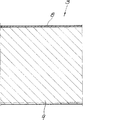
該流体供給クッションの細部は、図2の断面図に明らかに示されている。流体供給クッションは流体気密な後方壁2を有し、該後方壁は、シェルの形態を有しており、そして、PETフィルムから深絞りされたものである。その流体供給クッションの対向する前方側には、有孔弾性フィルム3が配置されており、これは、周囲を囲むホットシール継ぎ目4によって、該後方壁2と接合されている。前方壁としての該弾性フィルム3と該後方壁2との間には、流体受容コア5が配置されており、その際、その流体受容コアは、テキスタイル、不織布、綿、及び発泡プラスチックの群から選択される支持材料6を有し、そしてその際、該コア5中には、消毒液又は消毒ジェルの形態の流体が受容される。該支持材料6は、好ましくは、圧力弾性でもあるため、常に、図2に示す力が解放された流体供給クッションの形態が与えられることになる。
Details of the fluid supply cushion are clearly shown in the cross section of FIG. The fluid supply cushion has a fluid-tight
図1によれば、穿孔は、弾性フィルム3中の多数の切開部7によって形成される。それにより、切開部7は、その弾性フィルム3の弾性特性に基づく弁機能を有することが可能となり、その際、該切開部7は、その弾性フィルム3の変形されていない状態において少なくとも幅において閉じるため、流体は流体供給コア5中に保持される。
According to FIG. 1, the perforations are formed by a number of incisions 7 in the
使用者が触れることによって弾性フィルム3が変形するので、その弾性フィルム3自体は、個々の切開部において孔が開放され、そして流体が供給されるように変形する。
Since the
図1においては、その弾性フィルム3の露出表面に印字Aが提供されていることが更に示されている。一方では、その流体供給クッションは、価値の高い外観を有するべきであり、そして他方では、流体供給クッションが、消毒液デバイスの接触面として使用される部分であることも使用者に示さなければならない。
In FIG. 1, it is further shown that the print A is provided on the exposed surface of the
図3に示すように、弾性フィルム3は、本発明によれば、少なくとも二層の共押し出しフィルムから形成されており、これは、一つの非弾性の、流体供給クッションの表面を形成する、ポリオレフィンの薄いカバー層8、及び一つの弾性層9を有する。その弾性層9は、流体受容コア5の方向において配置されており、その際、対向して存在する薄いカバー層は、本発明によれば、10μm未満の厚さを有する。その弾性層9の、カバー層8に対する厚さの比は少なくとも10:1である。
As shown in FIG. 3, the
その具体的に示す実施形態において、外側の層は4μmの厚さを有し、そして、55重量%のLLDPE、40重量%のPPコポリマー及び残部のタルカム、加工助剤及び吸収剤を含有する。該吸収剤は、弾性層9を出ることのできる低分子量の成分を受容できるように特に適合される。
In its specifically illustrated embodiment, the outer layer has a thickness of 4 μm and contains 55% by weight LLDPE, 40% by weight PP copolymer and the rest of talcum, processing aids and absorbents. The absorbent is particularly adapted to accept low molecular weight components capable of exiting the
カバー層は、その印刷適正を改善するために、コロナ放電で処理される。 The cover layer is treated with corona discharge to improve its printability.
コア層は、全体として、196μmの厚さを有するため、その具体的な実施形態では、厚さの比は49:1である。 Since the core layer has a thickness of 196 μm as a whole, in its specific embodiment the thickness ratio is 49: 1.
弾性層は、40重量%までのSBS及び18%の酢酸ビニル含有量を有する35重量%のEVAからなる。さらに、その弾性層は、加工助剤、着色顔料、滑剤、ブロック防止剤及び安定剤を含有する。 The elastic layer consists of SBS up to 40% by weight and 35% by weight EVA with a vinyl acetate content of 18%. In addition, the elastic layer contains processing aids, color pigments, lubricants, block inhibitors and stabilizers.
その結果、顕著に非対称的な二層の共押し出しフィルムが得られる。 The result is a remarkably asymmetric two-layer co-extruded film.
図3に示す実施形態において、この二層の共押し出しフィルム自体は、三層用に調整された押し出し装置で製造される。その目的のために、弾性層9は、同じ材料の組成を有する二つの部分層から形成され、その際、その層構造中の中間の部分層は192μmの厚さを有し、そして、他方の部分層は4μmの厚さを有する。しかしながら、共押し出しフィルムの場合の層の移行部は、通常、もはや認識できない。というのも、共押し出しの場合の部分層は、互いに融合しているからである。その層の移行部は、図3においては鎖線によって示唆されている。
In the embodiment shown in FIG. 3, the two-layer co-extruded film itself is manufactured by an extrusion device adjusted for three layers. For that purpose, the
図4は、支持体1上に配置された流体供給クッションを示しており、そして、例えば、固定接合部によって保持することができ、それにより、該流体供給クッションは簡単に交換することができる。その支持体1は、例えば、接着テープ10によってドア等の接触面上に固定することができる。
FIG. 4 shows a fluid supply cushion disposed on support 1, which can be held, for example, by a fixed joint, whereby the fluid supply cushion can be easily replaced. The support 1 can be fixed on a contact surface such as a door by, for example, an
Claims (8)
前記弾性フィルム(3)が、切開部(7)によって穿孔され、その際、該切開部(7)が弁機能をもたらし、そして前記弾性フィルム(3)の変形されていない状態で閉じており、該前方壁は使用者が触れる接触面である
ことを特徴とする、上記の使用。 The perforated elastic film (3) is used as a front wall of a fluid supply cushion, wherein the fluid supply cushion is a fluid-tight rear wall (2) made of plastic, and the front wall and the rear wall. The use, which has a fluid receiving core (5) between (2) and the perforated elastic film (3), which is joined to the rear wall (2) by a hot sealing seam (4). The elastic film (3) is at least two co-extruded films having one elastic layer (9) and one cover layer (8) , and is a cover layer provided as a surface of the fluid supply cushion. (8) is made of polyolefin, wherein the thickness of the cover layer (8) is less than 15 μm, and the thickness ratio of the elastic layer (9) to the cover layer (8) is 10. more: 1 der is,
The elastic film (3) is perforated by the incision (7), at which time the incision (7) provides a valve function and is closed in an undeformed state of the elastic film (3). The use described above, wherein the front wall is a contact surface that the user touches .
Applications Claiming Priority (2)
| Application Number | Priority Date | Filing Date | Title |
|---|---|---|---|
| EP14198623.2 | 2014-12-17 | ||
| EP14198623.2A EP3034098B1 (en) | 2014-12-17 | 2014-12-17 | Use of a perforated elastic film as a front wall of a cushion that dispenses fluid |
Publications (3)
| Publication Number | Publication Date |
|---|---|
| JP2016117536A JP2016117536A (en) | 2016-06-30 |
| JP2016117536A5 JP2016117536A5 (en) | 2019-01-31 |
| JP6814373B2 true JP6814373B2 (en) | 2021-01-20 |
Family
ID=52144437
Family Applications (1)
| Application Number | Title | Priority Date | Filing Date |
|---|---|---|---|
| JP2015243828A Active JP6814373B2 (en) | 2014-12-17 | 2015-12-15 | Use of perforated elastic film as the front wall of the fluid supply cushion |
Country Status (6)
| Country | Link |
|---|---|
| US (1) | US9999324B2 (en) |
| EP (1) | EP3034098B1 (en) |
| JP (1) | JP6814373B2 (en) |
| CN (1) | CN105709250B (en) |
| CA (1) | CA2909953A1 (en) |
| ES (1) | ES2666656T3 (en) |
Families Citing this family (1)
| Publication number | Priority date | Publication date | Assignee | Title |
|---|---|---|---|---|
| WO2021179562A1 (en) * | 2020-03-12 | 2021-09-16 | 深圳市人民医院 | Persistently sanitizing shielding film |
Family Cites Families (17)
| Publication number | Priority date | Publication date | Assignee | Title |
|---|---|---|---|---|
| NZ205183A (en) * | 1982-08-13 | 1987-01-23 | Unilever Plc | Wiping cloth includes a liquid"active material" |
| US4832942A (en) | 1987-10-21 | 1989-05-23 | Crace Robert L | Touch effective disinfectant tape |
| US7179007B2 (en) * | 1999-10-08 | 2007-02-20 | The Procter & Gamble Company | Semi-enclosed applicators for distributing a substance onto a target surface |
| US6726386B1 (en) * | 1999-10-08 | 2004-04-27 | The Procter & Gamble Company | Semi-enclosed applicator and a cleaning composition contained therein |
| CA2392695C (en) | 1999-12-21 | 2007-09-11 | The Procter & Gamble Company | Laminate web comprising an apertured layer and method for manufacture thereof |
| US20030049410A1 (en) * | 2001-09-07 | 2003-03-13 | Munagavalasa Murthy S. | Film material and method of dispensing a volatile substance |
| DE10158345B4 (en) * | 2001-11-28 | 2005-11-24 | Nordenia Deutschland Gronau Gmbh | Monoaxially elastic laminate film |
| US7722589B2 (en) | 2005-08-31 | 2010-05-25 | Kimberly-Clark Worldwide, Inc. | Stretch activated article for delivering various compositions or functional elements |
| GB0610096D0 (en) | 2006-05-22 | 2006-06-28 | Walker Adam | Anti viral spreader |
| CN101100123A (en) * | 2006-07-06 | 2008-01-09 | 郭瑞林 | Seven-layer co-extrusion high-isolating packaging film |
| US7862877B2 (en) * | 2007-11-20 | 2011-01-04 | Basic Electronics, Inc. | Sanitary wrap |
| DE102008013284B3 (en) | 2008-03-08 | 2009-10-01 | Brinkmann, Uwe | Handle cover, especially for door handles |
| CN101905776A (en) * | 2010-07-26 | 2010-12-08 | 刘燕 | Multilayer coextrusion paper-like liquid packaging film |
| US8375521B1 (en) * | 2010-08-27 | 2013-02-19 | Andy S. Caron | Sanitary door handle cover |
| EP2471652A1 (en) * | 2010-12-28 | 2012-07-04 | Nordenia Technologies GmbH | Elastomer laminate and method for its production |
| US9123257B2 (en) * | 2012-01-18 | 2015-09-01 | Julio Vicente | Device for facilitating detection of hygienic hand washing |
| GB201208282D0 (en) | 2012-05-11 | 2012-06-20 | Surfaceskins Ltd | Delivery device |
-
2014
- 2014-12-17 ES ES14198623.2T patent/ES2666656T3/en active Active
- 2014-12-17 EP EP14198623.2A patent/EP3034098B1/en not_active Not-in-force
-
2015
- 2015-10-22 CA CA2909953A patent/CA2909953A1/en not_active Abandoned
- 2015-11-13 US US14/940,888 patent/US9999324B2/en active Active
- 2015-12-04 CN CN201510885572.7A patent/CN105709250B/en not_active Expired - Fee Related
- 2015-12-15 JP JP2015243828A patent/JP6814373B2/en active Active
Also Published As
| Publication number | Publication date |
|---|---|
| CN105709250B (en) | 2020-10-16 |
| CN105709250A (en) | 2016-06-29 |
| CA2909953A1 (en) | 2016-06-17 |
| JP2016117536A (en) | 2016-06-30 |
| US20160174775A1 (en) | 2016-06-23 |
| EP3034098A1 (en) | 2016-06-22 |
| ES2666656T3 (en) | 2018-05-07 |
| EP3034098B1 (en) | 2018-02-14 |
| US9999324B2 (en) | 2018-06-19 |
Similar Documents
| Publication | Publication Date | Title |
|---|---|---|
| US9867891B2 (en) | Delivery device | |
| US20200056400A1 (en) | Surface mountable delivery device | |
| US20220047747A1 (en) | Liquid or gel delivery devices | |
| US7699166B2 (en) | Package for wipes | |
| AU2007290048B2 (en) | Package for wipes | |
| JP2002194128A5 (en) | ||
| JP2014024599A (en) | Polyethylene bag opener | |
| JP6814373B2 (en) | Use of perforated elastic film as the front wall of the fluid supply cushion | |
| RU2016140366A (en) | MICROSTRUCTURED MULTI-LAYERED ELASTIC LAYERED MATERIALS WITH INCREASED STRENGTH AND ELASTICITY AND METHODS FOR PRODUCING THEM | |
| WO2019187886A1 (en) | Pad implement for toilet seat disinfection | |
| KR200484545Y1 (en) | Wet tissue package | |
| JP4343715B2 (en) | Non-slip material and method for producing the same | |
| CN203379357U (en) | Multilayer nasal cavity cleaning fingerstall | |
| CN201821978U (en) | Breathable film fingerstall | |
| JP3230481U (en) | Western-style toilet sterilization and disinfection materials | |
| GB2460269A (en) | Toilet tissue paper mitten | |
| KR102340030B1 (en) | Cosmetic applicator having indicator | |
| US20150067945A1 (en) | Disposable Wipe | |
| WO2011116734A1 (en) | Disposable sanitary sheet, especially for use in wc | |
| TWM612951U (en) | Sterilization unit | |
| JP2002165870A (en) | Deodorant sheet | |
| CN113908418A (en) | Disinfecting product for preventing contact infection | |
| JP2014198589A (en) | Resin bag opening tool | |
| WO2009087246A8 (en) | Dual-surface base element for disposable and recyclable cleaning articles | |
| TWM468409U (en) | Photocatalyst protecting film |
Legal Events
| Date | Code | Title | Description |
|---|---|---|---|
| A521 | Written amendment |
Free format text: JAPANESE INTERMEDIATE CODE: A523 Effective date: 20181207 |
|
| A621 | Written request for application examination |
Free format text: JAPANESE INTERMEDIATE CODE: A621 Effective date: 20181207 |
|
| A977 | Report on retrieval |
Free format text: JAPANESE INTERMEDIATE CODE: A971007 Effective date: 20191011 |
|
| A131 | Notification of reasons for refusal |
Free format text: JAPANESE INTERMEDIATE CODE: A131 Effective date: 20191023 |
|
| A601 | Written request for extension of time |
Free format text: JAPANESE INTERMEDIATE CODE: A601 Effective date: 20200106 |
|
| A521 | Written amendment |
Free format text: JAPANESE INTERMEDIATE CODE: A523 Effective date: 20200421 |
|
| TRDD | Decision of grant or rejection written | ||
| A01 | Written decision to grant a patent or to grant a registration (utility model) |
Free format text: JAPANESE INTERMEDIATE CODE: A01 Effective date: 20200930 |
|
| A601 | Written request for extension of time |
Free format text: JAPANESE INTERMEDIATE CODE: A601 Effective date: 20201027 |
|
| A521 | Written amendment |
Free format text: JAPANESE INTERMEDIATE CODE: A523 Effective date: 20201124 |
|
| A711 | Notification of change in applicant |
Free format text: JAPANESE INTERMEDIATE CODE: A711 Effective date: 20201124 |
|
| A61 | First payment of annual fees (during grant procedure) |
Free format text: JAPANESE INTERMEDIATE CODE: A61 Effective date: 20201126 |
|
| A521 | Written amendment |
Free format text: JAPANESE INTERMEDIATE CODE: A821 Effective date: 20201124 |
|
| R150 | Certificate of patent or registration of utility model |
Ref document number: 6814373 Country of ref document: JP Free format text: JAPANESE INTERMEDIATE CODE: R150 |