JP6812259B2 - Image reader and image forming device - Google Patents
Image reader and image forming device Download PDFInfo
- Publication number
- JP6812259B2 JP6812259B2 JP2017017543A JP2017017543A JP6812259B2 JP 6812259 B2 JP6812259 B2 JP 6812259B2 JP 2017017543 A JP2017017543 A JP 2017017543A JP 2017017543 A JP2017017543 A JP 2017017543A JP 6812259 B2 JP6812259 B2 JP 6812259B2
- Authority
- JP
- Japan
- Prior art keywords
- image
- document
- reading
- transparent member
- adhesive
- Prior art date
- Legal status (The legal status is an assumption and is not a legal conclusion. Google has not performed a legal analysis and makes no representation as to the accuracy of the status listed.)
- Active
Links
Images


Landscapes
- Facsimile Heads (AREA)
- Facsimiles In General (AREA)
- Facsimile Scanning Arrangements (AREA)
Description
本発明は、画像読取装置及びこれを備えた画像形成装置に関する。 The present invention relates to an image reader and an image forming apparatus including the image reader.
従来、原稿トレイ等に積載された原稿を一枚ずつ自動的に給送して搬送しながら、順次搬送される原稿の画像情報を読取可能な画像読取装置が用いられている。画像読取装置として、原稿を給送するADF(Auto Document Feeder)側と、原稿台ガラスを備えたスキャナ部側とのそれぞれに読取センサを配置し、原稿の両面を同時に読取可能とした装置が提案されている(特許文献1)。読取センサは、原稿に向け照射した光の反射光を撮像素子に結像して光電変換することにより原稿の画像情報を読み取るものであり、ADF側の読取センサはホルダ内に収容されている。 Conventionally, an image reading device capable of reading image information of sequentially conveyed originals has been used while automatically feeding and conveying the originals loaded on an original tray or the like one by one. As an image reading device, a device has been proposed in which reading sensors are arranged on the ADF (Auto Document Feeder) side for feeding the document and the scanner unit side provided with the platen glass so that both sides of the document can be read at the same time. (Patent Document 1). The reading sensor reads the image information of the document by forming an image of the reflected light of the light emitted toward the document on the image sensor and performing photoelectric conversion, and the reading sensor on the ADF side is housed in the holder.
ホルダには、ガラス(あるいは透明プラスチック等)で板状に形成されたコンタクトガラスが、画像情報を読み取る側の原稿の一面に対向するように取り付けられている。コンタクトガラスは、読取センサにより原稿に向けて照射される光を透過し、また光の照射に伴い原稿で反射された反射光を透過する。読取センサは、コンタクトガラスを通して受光される反射光に基づいて画像情報を読取位置で読み取る。 A contact glass formed of glass (or transparent plastic or the like) in a plate shape is attached to the holder so as to face one side of the document on the side for reading image information. The contact glass transmits the light emitted toward the document by the reading sensor, and also transmits the reflected light reflected by the document due to the irradiation of the light. The reading sensor reads the image information at the reading position based on the reflected light received through the contact glass.
また、ホルダにはADF側の読取センサの読取位置と異なる位置に、詳しくはスキャナ部側の読取センサにより照射された光がコンタクトガラスを通過し得る位置に、コンタクトガラスに重ね合されて白色部材が配置されている。白色部材は、スキャナ部側の読取センサによる読取画像の背景として配置される。 In addition, the holder is superposed on the contact glass at a position different from the reading position of the reading sensor on the ADF side, specifically at a position where the light emitted by the reading sensor on the scanner unit side can pass through the contact glass. Is placed. The white member is arranged as a background of the image read by the reading sensor on the scanner unit side.
ところで、最近では画像読取装置においてもより一層の低コスト化と小型化が望まれている。そこで、ホルダにコンタクトガラスを取り付けるのに、比較的にコストが低い両面テープを用いることが考えられる。しかしながら、両面テープを用いる場合、両面テープによる接着強度を確保できるだけの接着領域をコンタクトガラスに確保しなければならず、その接着領域は読取センサの読取位置や白色部材が重ね合わされる位置から外れた位置でなければならない。そのため、両面テープの接着領域の分だけコンタクトガラスは大型化する。コンタクトガラスが大型化すれば、それを取り付けるホルダも大きくせざるを得ず、これは小型化に反する。 By the way, recently, it is desired to further reduce the cost and size of the image reading device. Therefore, it is conceivable to use double-sided tape, which has a relatively low cost, to attach the contact glass to the holder. However, when using double-sided tape, it is necessary to secure an adhesive area on the contact glass that can secure the adhesive strength of the double-sided tape, and the adhesive area deviates from the reading position of the reading sensor and the position where the white member is overlapped. Must be in position. Therefore, the size of the contact glass is increased by the amount of the adhesive area of the double-sided tape. As the size of the contact glass increases, the holder to which it is attached must also be increased, which is contrary to the miniaturization.
これに対し、両面テープを用いずに液体接着剤を用いてホルダにコンタクトガラスを取り付ければ、両面テープより接着領域を縮小でき、小型化に資する。ただし、液体接着剤は両面テープに比べて高価であり、また接着領域から周りにはみ出さない適切な量で塗布することが難しく、両面テープを用いる場合に比べ手間がかかることから、コストが高くなりがちである。以上のことから、小型化と低コスト化とを両立した画像読取装置が従来から望まれていたが、未だそのようなものは提案されていない。 On the other hand, if the contact glass is attached to the holder using a liquid adhesive without using the double-sided tape, the adhesive area can be reduced as compared with the double-sided tape, which contributes to miniaturization. However, the liquid adhesive is more expensive than the double-sided tape, it is difficult to apply it in an appropriate amount that does not protrude from the adhesive area, and it takes more time than using the double-sided tape, so the cost is high. It tends to be. From the above, an image reader that achieves both miniaturization and cost reduction has been conventionally desired, but such an image reader has not yet been proposed.
本発明は上記問題に鑑みてなされたもので、小型化と低コスト化とを両立した画像読取装置、及びこれを備えた画像形成装置を提供することを目的とする。 The present invention has been made in view of the above problems, and an object of the present invention is to provide an image reading device that achieves both miniaturization and cost reduction, and an image forming device including the same.
本発明に係る画像読取装置は、原稿が積載される積載部と、前記積載部に積載された原稿を搬送方向に搬送する搬送部と、第一の透明部材と、前記搬送部によって搬送される原稿の第一面の画像を読取位置において前記第一の透明部材を介して読み取る第一読取部と、を有する原稿搬送ユニットと、第二の透明部材と、前記搬送部によって搬送される原稿の第二面の画像を前記第二の透明部材を介して読み取る第二読取部と、を有し、前記原稿搬送ユニットが回動可能に取り付けられる読取ユニットと、を備え、前記第一読取部は、前記第一面の画像を読み取る読取素子と、前記第二読取部によって読み取られる白色部材と、前記読取素子及び前記白色部材を保持すると共に、前記第一の透明部材が接着されて前記第一の透明部材を保持する保持部材と、を有し、前記白色部材は、前記原稿搬送ユニットが前記読取ユニットに対して閉じた状態において、鉛直方向において前記第一の透明部材と前記保持部材との間に設けられ、且つ、前記搬送方向において前記第一の透明部材の上流側の端部と下流側の端部との間に設けられ、前記保持部材は、前記搬送方向において、前記読取位置に関して前記白色部材とは反対側の前記第一の透明部材の第一領域が接着される第一接着部と、前記読取位置に関して前記白色部材と同じ側の前記第一の透明部材の第二領域が接着される第二接着部と、を有し、前記搬送方向に交差する幅方向において、前記読取素子が読み取り可能な領域よりも外側の領域に、前記第一の透明部材が接着される第三接着部を有し、前記第一接着部及び前記第三接着部においては、両面テープにより前記第一の透明部材と前記保持部材とが接着され、前記第二接着部においては、液体接着剤により前記第一の透明部材と前記保持部材とが接着され、前記第二接着部の前記搬送方向の長さは、前記第一接着部の前記搬送方向の長さよりも短い、ことを特徴とする。 The image reading device according to the present invention is conveyed by a loading section on which documents are loaded, a transport section that transports the documents loaded on the loading section in the transport direction, a first transparent member, and the transport section. A document transfer unit having a first reading unit that reads an image on the first surface of a document through the first transparent member at a reading position, a second transparent member, and a document conveyed by the transfer unit. The first reading unit includes a second reading unit that reads an image on the second surface via the second transparent member, and a reading unit to which the document transport unit is rotatably attached. A reading element that reads an image on the first surface, a white member that is read by the second reading unit, the reading element, and the white member are held, and the first transparent member is adhered to the first transparent member. The white member has a holding member for holding the transparent member of the above, and the white member is a state in which the document transport unit is closed with respect to the reading unit, and the first transparent member and the holding member are in the vertical direction. The holding member is provided between the upstream end and the downstream end of the first transparent member in the transport direction, and the holding member is provided in the transport direction with respect to the reading position. The first adhesive portion to which the first region of the first transparent member on the opposite side of the white member is bonded and the second region of the first transparent member on the same side as the white member with respect to the reading position are A third that has a second adhesive portion to be bonded and the first transparent member is bonded to a region outside the region that can be read by the reading element in the width direction intersecting the transport direction. It has an adhesive portion, and in the first adhesive portion and the third adhesive portion , the first transparent member and the holding member are adhered by a double-sided tape, and in the second adhesive portion, a liquid adhesive is used. The first transparent member and the holding member are bonded to each other, and the length of the second bonded portion in the transport direction is shorter than the length of the first bonded portion in the transport direction.
本発明では、両面テープにより第一の透明部材と保持部材とが接着状態とされる第一接着部よりシート搬送方向の長さが小さい第二接着部で、液体接着剤により第一の透明部材と保持部材とを接着状態とし、画像読取装置の小型化と低コスト化とを両立し得る。
In the present invention, the second adhesive portion length of the sheet conveyance direction is smaller than the first adhesive portion and the holding member and the first transparent member is an adhesive state by means of a double-sided tape, the first transparent member by a liquid adhesive And the holding member are adhered to each other , so that the image reader can be miniaturized and the cost can be reduced at the same time.
以下、本実施形態の画像読取装置及び画像形成装置について、図面を参照しながら説明する。 Hereinafter, the image reading device and the image forming device of the present embodiment will be described with reference to the drawings.
[画像形成装置]
本実施形態の画像形成装置について、図1(a)乃至図2を用いて説明する。画像形成装置100は、例えば電子写真方式のレーザビームプリンタである。図1(a)に示すように、画像形成装置100は、プリンタ本体70と、プリンタ本体70の上部に装着された画像読取部10とを備えている。
[Image forming device]
The image forming apparatus of this embodiment will be described with reference to FIGS. 1 (a) and 2 (2). The
プリンタ本体70は、プリンタ本体70を形成する筐体70Aの内部に画像形成エンジン60を有している。画像形成エンジン60は、図1(b)に示すように、電子写真方式の画像形成ユニットPUと、定着装置7とを備えている。画像形成ユニットPUでは画像形成動作の開始が指令されると、感光体である感光ドラム1が回転し、ドラム表面が帯電装置2によって一様に帯電される。すると、露光装置3が画像読取部10又は外部のコンピュータから送信された画像データに基づいてレーザ光を変調して出力し、ドラム表面を走査して静電潜像を形成する。この静電潜像が現像装置4から供給されるトナーによって現像されることで、ドラム表面にトナー像が形成される。
The printer
このような画像形成動作に並行して、不図示のカセット又は手差しトレイからシートが給送される。給送されたシートは、画像形成ユニットPUによる上記した画像形成動作の進行に合わせて画像形成ユニットPUへと搬送される。そして、ドラム表面に形成されたトナー像は、転写ローラ5によってシートに転写される。トナー像の転写後にドラム表面に残ったトナーは、クリーニング装置6によって回収される。トナー像が転写されたシートは、定着装置7へと受け渡される。定着装置7では、シートをローラ対で挟持して加熱及び加圧する。これにより、トナーが溶融及び固着し、シートに画像が定着する。画像が定着されたシートは、不図示の排出ローラ対によって筐体70Aの外部に排出される。なお、ここで言うシートとは普通紙の他に、コート紙等の特殊紙、封筒やインデックス紙等の特殊形状からなる記録材、及びオーバーヘッドプロジェクタ用のプラスチックフィルムや布などを含む。
In parallel with such an image forming operation, a sheet is fed from a cassette or a manual feed tray (not shown). The fed sheet is conveyed to the image forming unit PU in accordance with the progress of the image forming operation described above by the image forming unit PU. Then, the toner image formed on the drum surface is transferred to the sheet by the
また、プリンタ本体70には制御部80が搭載されている。制御部80は、画像形成装置100全体の動作を統括制御する中央処理装置(CPU)と、CPUが実行するプログラムや画像情報及び設定情報を記憶するメモリを含む。制御部80は、画像形成エンジン60を制御して、原稿D1とは別のシート(上記した不図示のカセット又は手差しトレイから給送されたシート)に画像を形成させる画像形成動作を実行可能である。
Further, the printer
なお、画像形成エンジン60は、原稿D1とは別のシートに画像を形成可能な画像形成手段の一例であり、上述の直接転写方式に代えて中間転写体を含む中間転写方式の構成を用いてもよく、インクジェット方式等の他の機構を用いてもよい。
The
図2に示すように、画像読取装置の一例である画像読取部10は、原稿トレイ14に載置された原稿D1(図1(a)参照)を自動的に給送するADF11と、上面に原稿台ガラス30が設けられたスキャナ部12とを備えている。シート給送装置の一例であるADF11(Auto Document Feeder)は、原稿台ガラス30を上面側で露出させることが可能なように、不図示のヒンジ等によってスキャナ部12に対し回動可能に支持されている。即ち、画像読取部10は図示を省略したが、スキャナ部12を構成する本体フレームと、ADF11を構成するフレームであって、本体フレームに対し開閉可能な開閉フレームとを有している。なお、原稿D1として用いられるシートは、白紙でも、片面又は両面に画像が形成されていてもよい。
As shown in FIG. 2, the
ADF11は、図1(a)に示すように、原稿D1が載置される原稿トレイ14と、原稿トレイ14から給送された原稿D1を搬送する原稿搬送部15と、原稿D1が排出される排出トレイ29とを備えている。原稿搬送部15は、略U字状に湾曲した原稿搬送路22を有する。原稿搬送部15には、原稿搬送路22に沿ってピックアップローラ17、分離ローラ18、分離パッド19、原稿ストッパ20、原稿有無センサ21、搬送ローラ対23、排出ローラ対24、及び原稿エッジセンサ25が配置されている。
As shown in FIG. 1A, the
ADF11及びスキャナ部12には、それぞれ原稿D1の画像情報を読取可能な読取センサ16、26が配置されている。読取センサ16、26としては、例えば光源から発せられる光を原稿D1の画像情報面に照射し、原稿D1の画像情報面で反射した反射光をレンズで撮像素子に結像して画像情報を読み取る、密着型イメージセンサが用いられる(後述する図3参照)。
Reading
ここで、画像読取部10がADF11によって原稿D1を給送しながら原稿D1の画像情報を読み取る動作(流し読み動作)について、図1(a)を用いて説明する。まず、利用者が原稿D1を原稿トレイ14に載置する。このとき、原稿D1の先端位置が原稿ストッパ20によって規制されると共に、原稿有無センサ21によって原稿D1が検知される。制御部80は、原稿有無センサ21の検知結果に基づき原稿が原稿トレイ14上に載置されているか否かを判定し、原稿が原稿トレイ14上に載置されている場合に以下の動作の制御を実行し得る。
Here, an operation (scanning operation) in which the
利用者が不図示の操作部を介して読取開始を指示すると、不図示の駆動部から供給される駆動力によって原稿ストッパ20が押し下げられ、ピックアップローラ17によって原稿D1が分離ローラ18と分離パッド19の間の分離部まで搬送される。すると、分離パッド19によって最上位の原稿D1が他の原稿から分離され、分離された原稿D1は分離ローラ18によって原稿搬送路22に送られる。原稿搬送路22に送られた原稿D1は、搬送ローラ対23によって原稿搬送路22に沿って、読取センサ16、26による読取位置へ向け搬送される。
When the user instructs the start of scanning via an operation unit (not shown), the
その後、原稿エッジセンサ25により原稿D1の先端部が検知されると、原稿D1の先端部が原稿エッジセンサ25の検知位置から所定量搬送されるタイミングで読取センサ16、26による画像情報の読み取りが開始される。ADF11に配置された読取センサ26は原稿D1の第一面から画像情報を読み取り、スキャナ部12に配置された読取センサ16は原稿D1の第一面とは反対側の第二面から画像情報を読み取る。即ち、搬送される原稿D1の第一面及び第二面両面の画像情報が同時に読み取られる。
After that, when the tip of the document D1 is detected by the
読取センサ16、26の読取位置を通過した原稿D1は、排出ローラ対24に向かって搬送される。そして、原稿エッジセンサ25により原稿D1の後端部が検知されると、原稿D1の後端部が原稿エッジセンサ25の検知位置から所定量搬送されるタイミングで読取センサ16、26による画像情報の読み取りが終了する。そして、原稿D1は、排出ローラ対24によって排出トレイ29へ排出される。このような読取動作は、原稿トレイ14に載置された原稿が存在しないことが原稿有無センサ21によって検知されるまで繰り返される。
The document D1 that has passed the reading positions of the
なお、画像読取部10は上記した流し読み動作の他に、ADF11による原稿D1の給送を行うことなしに、利用者が原稿台ガラス30に載置した原稿D1の画像情報を読み取る動作(固定読み動作)を実行可能である。この場合、原稿台ガラス30に原稿が載置された状態で、スキャナ部12の読取センサ16が原稿台ガラス30に沿って副走査方向(図1において左右方向)に移動することで、原稿D1の第二面片面の画像情報が読み取られる。
In addition to the above-mentioned scanning operation, the
ここで、画像読取部10の構成について、図3を用いて説明する。図3は、図1に記号Xを付した画像読取部10の一部範囲を拡大して示す一部拡大図である。図3に示すように、各読取センサ16(26)は、導光体161(261)と、レンズアレイ162(262)と、撮像素子163(263)とを備えている。読取センサ16(26)は、レンズアレイ162(262)から発せられる光を導光体161(261)によって原稿搬送路22を搬送される原稿D1へ向けて照射する。そして、読取センサ16(26)は、光の照射に伴い原稿D1で反射された反射光を撮像素子163(263)に結像して光電変換することにより、原稿D1の画像情報を読み取る。
Here, the configuration of the
以下、原稿搬送方向における読取センサ16の読取位置、即ちレンズアレイ162の光軸位置を第一読取位置Paとし、読取センサ26の読取位置、即ちレンズアレイ262の光軸位置を第二読取位置Pbとする。なお、画像読取部10における原稿搬送方向(図3において右方向)はシート搬送方向に相当し、原稿搬送路22はシート搬送路に相当する。また、原稿搬送方向に交差する方向(図3において奥行方向)を原稿(シート)の幅方向と呼び、原稿搬送方向及び原稿の幅方向に交差する方向(図3において上下方向)を原稿(シート)の厚さ方向と呼ぶ。
Hereinafter, the reading position of the reading
別の読取手段としての読取センサ16は、キャリッジ160に支持されている。キャリッジ160は、スキャナ部12の本体フレームに対して副走査方向(図3において左右方向)に移動可能である。キャリッジ160は固定読み動作の際に原稿台ガラス30の下方を通して副走査方向に移動されるが、流し読み動作の際には移動されることなく図示の位置で静止状態に維持される。
A reading
スキャナ部12の本体フレームには、第一読取位置Paにおいて読取センサ16を覆うようにコンタクトガラス50が取付けられている。また、読取センサ16とキャリッジ160との間には、読取センサ16をコンタクトガラス50(あるいは原稿台ガラス30)へ向けて付勢するバネ等の押圧部材31が配置されている。読取センサ16は、固定読み動作の場合、原稿台ガラス30を通して原稿D1の第二面から画像情報を読み取り、流し読み動作の場合、コンタクトガラス50を通して原稿D1の第二面の画像情報を読み取る。
A
他方、読取手段としての読取センサ26はホルダ27に収容され、ホルダ27ごと原稿搬送路22に対して読取センサ16とは反対側に配置される。詳しくは後述するように(図4及び図5参照)、ホルダ27には透過部材としてのコンタクトガラス28が取り付け可能である。
On the other hand, the reading
ホルダ27はフレーム体としてのADF11のフレーム110により、第二読取位置Pbにおける原稿D1の厚さ方向に揺動可能に支持されている。ホルダ27とフレーム110との間には、ホルダ27をコンタクトガラス50へ向けて付勢するバネ等の押圧部材32が配置されている。これにより、コンタクトガラス50とコンタクトガラス28との間に、原稿搬送路22が形成される。読取センサ26は流し読み動作の際に、コンタクトガラス28を通して原稿搬送路22を搬送される原稿D1の第二面の画像情報を読み取る。
The
本実施形態の場合、流し読み動作における排出ローラ対24の周速は、搬送ローラ対23の周速に比べて大きく設定されている(図1参照)。言い換えると、画像読取部10の上流に配置される第一搬送ローラ対の周速が、画像読取部10の下流に配置される第二搬送ローラ対の周速に比べて小さくなるように設定されている。こうすると、搬送ローラ対23と排出ローラ対24との間における原稿D1の撓みやシワが低減されるので、搬送動作の安定性向上及び読取画像の画質向上の効果が得られやすい。なお、搬送ローラ対23及び排出ローラ対24は、いずれも原稿D1(シート)を搬送するシート搬送手段の一例であり、これに限らない。シート搬送手段としては、搬送ベルト等の他の搬送部材を用いてもよい。
In the case of this embodiment, the peripheral speed of the
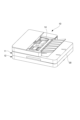
ホルダ27について、図3を参照しながら図4及び図5を用いて説明する。図4に示すように、収容体としてのホルダ27は読取センサ26(図3参照)を収容し保持する収容部27aと、収容部27aに支持された支持枠部27bとを有する。収容部27aには開口部27cが形成され、収容部27a内(収容体内)に収容されている読取センサ26から開口部27cを通じて収容部27a外へ光を照射可能になっている。即ち、流し読み動作の際に原稿搬送路22を搬送される原稿D1は、開口部側で読取センサ26に相対する。
The
支持枠部27bは、収容部27aの開口部27cに設けられる。支持枠部27bには、第一読取位置Paにおいて読取センサ16(より詳しくはレンズアレイ162)に対向するように、光を反射する白色部材の一例である白色シート33が設けられている。また、支持枠部27bは、透過部材としてのコンタクトガラス28を取り付ける取付領域(後述する接着部41〜44)を有している。コンタクトガラス28は、白色シート33を支持枠部27bとの間で挟むように支持枠部27bに取り付けられる。これは、白色シート33をコンタクトガラス28よりもホルダ内に配置することで、白色シート33が汚れるのを防ぐためである。白色シート33は白色等の明度の高い部材であり、支持枠部27bとコンタクトガラス28とに挟まれて、読取センサ16による読取画像の背景として機能する。
The
コンタクトガラス28は開口部27cを塞ぐように取り付けられるが、コンタクトガラス28はガラスあるいは透明プラスチック等で光を透過可能に板状に形成されている。それ故、読取センサ26により照射される光はコンタクトガラス28を通じてホルダ外に透過し、また原稿D1で反射された反射光はコンタクトガラス28を通じてホルダ内に透過し得る。
The
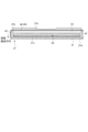
図5に示すように、支持枠部27bはコンタクトガラス28を接着して取り付け可能な接着部41〜44を有している。本実施形態の場合、下流接着部41は原稿搬送方向の下流側、端部接着部としての接着部42、43はそれぞれ原稿の幅方向の両端部、上流接着部44は原稿搬送方向の上流側の、開口部27cを囲むように支持枠部27bの四辺に形成されている。これら接着部41〜44にコンタクトガラス28が接着されると、ホルダ27は密閉される。こうしてホルダ27を密閉することで、外部からホルダ内への埃等の侵入を防ぎ、読取センサ26の誤検知等を防止している。
As shown in FIG. 5, the
ホルダ27は、原稿搬送方向における読取センサ26に対して白色シート33とは反対側の端部27dとの間に、第一接着部としての下流接着部41を有する。また、ホルダ27は、白色シート33に対して読取センサ26とは反対側の端部27eとの間に、第二接着部としての上流接着部44を有する。上流接着部44は白色シート33を避けて、白色シート33よりも原稿搬送方向の上流側の一辺に形成されている。上流接着部44の原稿搬送方向の長さは、下流接着部41の原稿搬送方向の長さよりも小さい。例えば、下流接着部41の原稿搬送方向の長さは4〜6mm程度であり、上流接着部44(より詳しくは後述する溝90)の原稿搬送方向の長さは1〜2mm程度である。なお、上流接着部44と下流接着部41の原稿の幅方向長さは略同一に形成されている。また、接着部42と接着部43に関しては、原稿搬送方向の長さ、原稿の幅方向長さとも略同一に形成されていればよい。
The
本実施形態の場合、コンタクトガラス28と支持枠部27bとは、接着部44以外(第二接着部以外)の他の接着部41〜43において両面テープにより接着状態とされる。即ち、接着部41〜43には両面テープが貼り付けられている。両面テープを貼り付けやすくまた剥がれ難くするために、接着部41〜43は平らで滑らかな平滑面を有する。なお、接着部41に貼り付けられる両面テープは、その原稿搬送方向の長さが接着部41と略同一である。
In the case of the present embodiment, the
他方、コンタクトガラス28と支持枠部27bとは、上流接着部44において両面テープに比べ単位面積当たりの接着力が強い液体接着剤により接着状態とされる。液体接着剤としては、例えば紫外線を照射することで硬化する紫外線硬化型の接着剤などが用いられる。これは、上記のように上流接着部44は原稿搬送方向の長さが下流接着部41に比べて小さいがために、下流接着部41と同じように両面テープを用いて接着すると、接着力が足りない(弱い)からである。即ち、仮に上流接着部44において両面テープを用いるとなると、上流接着部44での接着力を確保するため、両面テープの原稿搬送方向の長さを大きくせざるを得ない。しかしながら、上流接着部44は白色シート33に隣接するが故に、両面テープの原稿搬送方向の長さを大きくすることは難しい。そこで、両面テープの原稿搬送方向の長さを大きくするため、コンタクトガラス28を原稿搬送方向の上流側に大きくすることが考えられるが、これは装置の小型化に反するため採用し難い。
On the other hand, the
上記のように、上流接着部44で液体接着剤を用いて接着する場合、上流接着部44から液体接着剤がはみ出してしまうと、はみ出した液体接着剤によりコンタクトガラス28や白色シート33が汚れる虞がある。これを避けるために、上流接着部44は液体接着剤を塗布可能な溝90(図3参照)を有している。液体接着剤は溝90に流し入れられるようにして塗布されることで、溝90の周りにはみ出さない適切な量でコンタクトガラス28を支持枠部27bに接着できる。
As described above, when the upstream
以上のように、本実施形態では、ホルダ27(詳しくは支持枠部27b)とコンタクトガラス28とを、白色シート33を配置した原稿搬送方向の上流側の一辺では液体接着剤を用いて接着状態とし、他の三辺では両面テープを用いて接着状態とする。こうして一辺を除き、液体接着剤よりも安価な両面テープを用いてコンタクトガラス28を接着することで、コストを抑制できる。また、両面テープよりも単位面積当たりの接着力が強い液体接着剤を用いることで、上流接着部44はその原稿搬送方向の長さが下流接着部41の原稿搬送方向の長さよりも小さくて済む。即ち、その分、コンタクトガラス28ひいてはホルダ27を小さくすることができる。こうして、下流接着部41よりも原稿搬送方向の長さが小さい上流接着部44で液体接着剤を用いてホルダ27とコンタクトガラス28とを接着することにより、簡易な構成で画像読取装置の小型化と低コスト化とを両立することが実現できる。
As described above, in the present embodiment, the holder 27 (specifically, the
なお、上述した実施形態では、読取センサ26において白色シート33がレンズアレイ262よりも原稿搬送方向の上流側に配置されている場合を示したが(図3参照)、これに限られない。例えば、白色シート33がレンズアレイ262よりも原稿搬送方向の下流側に配置されている場合でも、本実施形態は適用可能である。即ち、ホルダ27とコンタクトガラス28とは、白色シート33を配置した原稿搬送方向の下流側の一辺で液体接着剤を用いて接着状態とされ、他の三辺で両面テープを用いて接着状態とされる。この場合、下流接着部41は、その原稿搬送方向の長さが上流接着部44よりも小さい。
In the above-described embodiment, the case where the
10・・・画像読取装置(画像読取部)、16・・・別の読取手段(読取センサ)、23・・・シート搬送手段(第一搬送ローラ対、搬送ローラ対)、24・・・シート搬送手段(第二搬送ローラ対、排出ローラ対)、26・・・読取手段(読取センサ)、27・・・収容体(ホルダ)、27d(27e)・・・端部、28・・・透過部材(コンタクトガラス)、33・・・白色部材(白色シート)、41・・・取付領域(第一接着部、下流接着部)、42(43)・・・取付領域(端部接着部、接着部)、44・・・取付領域(第二接着部、上流接着部)、60・・・画像形成手段(画像形成エンジン)、90・・・溝、100・・・画像形成装置、D1・・・原稿 10 ... Image reading device (image reading unit), 16 ... Another reading means (reading sensor), 23 ... Sheet transporting means (first transport roller pair, transport roller pair), 24 ... Sheet Conveying means (second transport roller pair, discharge roller pair), 26 ... reading means (reading sensor), 27 ... accommodating body (holder), 27d (27e) ... end, 28 ... transparent Member (contact glass), 33 ... White member (white sheet), 41 ... Mounting area (first adhesive part, downstream adhesive part), 42 (43) ... Mounting area (end adhesive part, adhesive) Part), 44 ... Mounting area (second adhesive part, upstream adhesive part), 60 ... Image forming means (image forming engine), 90 ... Groove, 100 ... Image forming device, D1 ...・ Manuscript
Claims (5)
第二の透明部材と、前記搬送部によって搬送される原稿の第二面の画像を前記第二の透明部材を介して読み取る第二読取部と、を有し、前記原稿搬送ユニットが回動可能に取り付けられる読取ユニットと、
を備え、
前記第一読取部は、前記第一面の画像を読み取る読取素子と、前記第二読取部によって読み取られる白色部材と、前記読取素子及び前記白色部材を保持すると共に、前記第一の透明部材が接着されて前記第一の透明部材を保持する保持部材と、を有し、
前記白色部材は、前記原稿搬送ユニットが前記読取ユニットに対して閉じた状態において、鉛直方向において前記第一の透明部材と前記保持部材との間に設けられ、且つ、前記搬送方向において前記第一の透明部材の上流側の端部と下流側の端部との間に設けられ、
前記保持部材は、前記搬送方向において、前記読取位置に関して前記白色部材とは反対側の前記第一の透明部材の第一領域が接着される第一接着部と、前記読取位置に関して前記白色部材と同じ側の前記第一の透明部材の第二領域が接着される第二接着部と、を有し、前記搬送方向に交差する幅方向において、前記読取素子が読み取り可能な領域よりも外側の領域に、前記第一の透明部材が接着される第三接着部を有し、
前記第一接着部及び前記第三接着部においては、両面テープにより前記第一の透明部材と前記保持部材とが接着され、
前記第二接着部においては、液体接着剤により前記第一の透明部材と前記保持部材とが接着され、
前記第二接着部の前記搬送方向の長さは、前記第一接着部の前記搬送方向の長さよりも短い、
ことを特徴とする画像読取装置。 The image of the first surface of the loading section on which the originals are loaded, the transport section for transporting the documents loaded on the loading section in the transport direction, the first transparent member, and the document transported by the transport section is read. A document transport unit having a first reading unit that reads through the first transparent member at a position, and
The document transport unit has a second transparent member and a second reading unit that reads an image of the second surface of the document transported by the transport unit via the second transparent member, and the document transport unit can rotate. With the reading unit attached to
With
The first reading unit holds a reading element that reads an image on the first surface, a white member that is read by the second reading unit, the reading element, and the white member, and the first transparent member. Has a holding member that is adhered to hold the first transparent member,
The white member is provided between the first transparent member and the holding member in the vertical direction in a state where the document transport unit is closed with respect to the reading unit, and the first in the transport direction. It is provided between the upstream end and the downstream end of the transparent member of
The holding member has a first adhesive portion to which the first region of the first transparent member opposite to the white member with respect to the reading position is adhered in the transport direction, and the white member with respect to the reading position. A region outside the region readable by the reading element in the width direction intersecting the transport direction , which has a second adhesive portion to which the second region of the first transparent member on the same side is bonded. Has a third adhesive portion to which the first transparent member is adhered.
In the first adhesive portion and the third adhesive portion , the first transparent member and the holding member are adhered to each other by a double-sided tape.
In the second adhesive portion, the first transparent member and the holding member are adhered to each other by a liquid adhesive.
The length of the second adhesive portion in the transport direction is shorter than the length of the first adhesive portion in the transport direction.
An image reader characterized by this.
ことを特徴とする請求項1に記載の画像読取装置。 The white member is provided on the upstream side in the transport direction with respect to the reading position.
The image reading device according to claim 1.
ことを特徴とする請求項1又は2に記載の画像読取装置。 The second adhesive portion has a groove to which the liquid adhesive can be applied.
The image reading device according to claim 1 or 2.
ことを特徴とする請求項1乃至3のいずれか1項に記載の画像読取装置。 The liquid adhesive is an ultraviolet curable adhesive.
The image reading device according to any one of claims 1 to 3 , wherein the image reading device is characterized.
前記画像読取装置によって読み取られた画像に基づいて、記録媒体に画像を形成する画像形成手段と、を備える、
ことを特徴とする画像形成装置。 The image reading device according to any one of claims 1 to 4 ,
An image forming means for forming an image on a recording medium based on an image read by the image reading device is provided.
An image forming apparatus characterized in that.
Priority Applications (1)
| Application Number | Priority Date | Filing Date | Title |
|---|---|---|---|
| JP2017017543A JP6812259B2 (en) | 2017-02-02 | 2017-02-02 | Image reader and image forming device |
Applications Claiming Priority (1)
| Application Number | Priority Date | Filing Date | Title |
|---|---|---|---|
| JP2017017543A JP6812259B2 (en) | 2017-02-02 | 2017-02-02 | Image reader and image forming device |
Publications (3)
| Publication Number | Publication Date |
|---|---|
| JP2018125752A JP2018125752A (en) | 2018-08-09 |
| JP2018125752A5 JP2018125752A5 (en) | 2020-03-12 |
| JP6812259B2 true JP6812259B2 (en) | 2021-01-13 |
Family
ID=63109779
Family Applications (1)
| Application Number | Title | Priority Date | Filing Date |
|---|---|---|---|
| JP2017017543A Active JP6812259B2 (en) | 2017-02-02 | 2017-02-02 | Image reader and image forming device |
Country Status (1)
| Country | Link |
|---|---|
| JP (1) | JP6812259B2 (en) |
Family Cites Families (4)
| Publication number | Priority date | Publication date | Assignee | Title |
|---|---|---|---|---|
| JPH039661A (en) * | 1989-06-06 | 1991-01-17 | Matsushita Graphic Commun Syst Inc | Reader |
| JPH0583480A (en) * | 1991-09-20 | 1993-04-02 | Pfu Ltd | Original reader |
| JP3746806B2 (en) * | 1995-02-28 | 2006-02-15 | ペンタックス株式会社 | Image reader |
| TWI690577B (en) * | 2015-03-12 | 2020-04-11 | 日商松下知識產權經營股份有限公司 | Photocationically polymerizable composition, bonding method, electronic device, and producing method thereof, as well as displaying device, and producing method thereof |
-
2017
- 2017-02-02 JP JP2017017543A patent/JP6812259B2/en active Active
Also Published As
| Publication number | Publication date |
|---|---|
| JP2018125752A (en) | 2018-08-09 |
Similar Documents
| Publication | Publication Date | Title |
|---|---|---|
| CN101673070B (en) | Document pressing apparatus, image reading apparatus and image forming apparatus with document pressing apparatus | |
| JP6661465B2 (en) | Image reading device and image forming device | |
| US7570400B2 (en) | Document reading device | |
| US10237443B2 (en) | Image reading apparatus and image forming apparatus | |
| JP5932149B2 (en) | Document reading apparatus and image forming apparatus having the same | |
| JP6812259B2 (en) | Image reader and image forming device | |
| JP4095054B2 (en) | Document reader | |
| JP3788128B2 (en) | Image reading apparatus, image reading method, and image forming apparatus | |
| JP6884591B2 (en) | Image reader and image forming device | |
| JP4089644B2 (en) | Document feeder | |
| JP6739984B2 (en) | Image reading apparatus and image forming apparatus | |
| JP2007336278A (en) | Image reader | |
| JP6936724B2 (en) | Document feeder, image reader and image forming device | |
| JP3420479B2 (en) | Image reading device and image forming device | |
| JP2008005360A (en) | Image reader | |
| JP6848914B2 (en) | An image reader and an image forming apparatus provided with the image reader. | |
| JP6906753B2 (en) | Image reader and image forming device | |
| US20180234576A1 (en) | Image reading apparatus and image forming apparatus | |
| JP2004075259A (en) | Paper conveyance device | |
| JP2016208132A (en) | Automatic document feeder and image forming apparatus including the same | |
| JP2006193314A (en) | Image reading device, and image forming device having the same | |
| JPH10236690A (en) | Image reader and image processor | |
| JP2006115294A (en) | Original reader | |
| JP2021125855A (en) | Image reading device and image forming apparatus | |
| JP5790323B2 (en) | Image reading apparatus and image forming apparatus provided with image reading apparatus |
Legal Events
| Date | Code | Title | Description |
|---|---|---|---|
| A521 | Written amendment |
Free format text: JAPANESE INTERMEDIATE CODE: A523 Effective date: 20200131 |
|
| A621 | Written request for application examination |
Free format text: JAPANESE INTERMEDIATE CODE: A621 Effective date: 20200131 |
|
| RD02 | Notification of acceptance of power of attorney |
Free format text: JAPANESE INTERMEDIATE CODE: A7422 Effective date: 20200206 |
|
| RD04 | Notification of resignation of power of attorney |
Free format text: JAPANESE INTERMEDIATE CODE: A7424 Effective date: 20200207 |
|
| A977 | Report on retrieval |
Free format text: JAPANESE INTERMEDIATE CODE: A971007 Effective date: 20200918 |
|
| A131 | Notification of reasons for refusal |
Free format text: JAPANESE INTERMEDIATE CODE: A131 Effective date: 20201006 |
|
| A521 | Written amendment |
Free format text: JAPANESE INTERMEDIATE CODE: A523 Effective date: 20201013 |
|
| TRDD | Decision of grant or rejection written | ||
| A01 | Written decision to grant a patent or to grant a registration (utility model) |
Free format text: JAPANESE INTERMEDIATE CODE: A01 Effective date: 20201117 |
|
| A61 | First payment of annual fees (during grant procedure) |
Free format text: JAPANESE INTERMEDIATE CODE: A61 Effective date: 20201216 |
|
| R151 | Written notification of patent or utility model registration |
Ref document number: 6812259 Country of ref document: JP Free format text: JAPANESE INTERMEDIATE CODE: R151 |