JP6812208B2 - Information processing equipment, printing system, information processing equipment control method, and program - Google Patents
Information processing equipment, printing system, information processing equipment control method, and program Download PDFInfo
- Publication number
- JP6812208B2 JP6812208B2 JP2016220401A JP2016220401A JP6812208B2 JP 6812208 B2 JP6812208 B2 JP 6812208B2 JP 2016220401 A JP2016220401 A JP 2016220401A JP 2016220401 A JP2016220401 A JP 2016220401A JP 6812208 B2 JP6812208 B2 JP 6812208B2
- Authority
- JP
- Japan
- Prior art keywords
- post
- processing
- print job
- image forming
- forming apparatus
- Prior art date
- Legal status (The legal status is an assumption and is not a legal conclusion. Google has not performed a legal analysis and makes no representation as to the accuracy of the status listed.)
- Active
Links
Images


Classifications
-
- B—PERFORMING OPERATIONS; TRANSPORTING
- B65—CONVEYING; PACKING; STORING; HANDLING THIN OR FILAMENTARY MATERIAL
- B65H—HANDLING THIN OR FILAMENTARY MATERIAL, e.g. SHEETS, WEBS, CABLES
- B65H29/00—Delivering or advancing articles from machines; Advancing articles to or into piles
- B65H29/58—Article switches or diverters
- B65H29/60—Article switches or diverters diverting the stream into alternative paths
-
- G—PHYSICS
- G03—PHOTOGRAPHY; CINEMATOGRAPHY; ANALOGOUS TECHNIQUES USING WAVES OTHER THAN OPTICAL WAVES; ELECTROGRAPHY; HOLOGRAPHY
- G03G—ELECTROGRAPHY; ELECTROPHOTOGRAPHY; MAGNETOGRAPHY
- G03G15/00—Apparatus for electrographic processes using a charge pattern
- G03G15/50—Machine control of apparatus for electrographic processes using a charge pattern, e.g. regulating differents parts of the machine, multimode copiers, microprocessor control
- G03G15/5075—Remote control machines, e.g. by a host
- G03G15/5083—Remote control machines, e.g. by a host for scheduling
-
- B—PERFORMING OPERATIONS; TRANSPORTING
- B65—CONVEYING; PACKING; STORING; HANDLING THIN OR FILAMENTARY MATERIAL
- B65H—HANDLING THIN OR FILAMENTARY MATERIAL, e.g. SHEETS, WEBS, CABLES
- B65H43/00—Use of control, checking, or safety devices, e.g. automatic devices comprising an element for sensing a variable
- B65H43/06—Use of control, checking, or safety devices, e.g. automatic devices comprising an element for sensing a variable detecting, or responding to, completion of pile
-
- G—PHYSICS
- G03—PHOTOGRAPHY; CINEMATOGRAPHY; ANALOGOUS TECHNIQUES USING WAVES OTHER THAN OPTICAL WAVES; ELECTROGRAPHY; HOLOGRAPHY
- G03G—ELECTROGRAPHY; ELECTROPHOTOGRAPHY; MAGNETOGRAPHY
- G03G15/00—Apparatus for electrographic processes using a charge pattern
- G03G15/55—Self-diagnostics; Malfunction or lifetime display
-
- G—PHYSICS
- G03—PHOTOGRAPHY; CINEMATOGRAPHY; ANALOGOUS TECHNIQUES USING WAVES OTHER THAN OPTICAL WAVES; ELECTROGRAPHY; HOLOGRAPHY
- G03G—ELECTROGRAPHY; ELECTROPHOTOGRAPHY; MAGNETOGRAPHY
- G03G15/00—Apparatus for electrographic processes using a charge pattern
- G03G15/65—Apparatus which relate to the handling of copy material
- G03G15/6552—Means for discharging uncollated sheet copy material, e.g. discharging rollers, exit trays
-
- G—PHYSICS
- G06—COMPUTING; CALCULATING OR COUNTING
- G06F—ELECTRIC DIGITAL DATA PROCESSING
- G06F3/00—Input arrangements for transferring data to be processed into a form capable of being handled by the computer; Output arrangements for transferring data from processing unit to output unit, e.g. interface arrangements
- G06F3/12—Digital output to print unit, e.g. line printer, chain printer
- G06F3/1201—Dedicated interfaces to print systems
- G06F3/1202—Dedicated interfaces to print systems specifically adapted to achieve a particular effect
- G06F3/1203—Improving or facilitating administration, e.g. print management
- G06F3/1204—Improving or facilitating administration, e.g. print management resulting in reduced user or operator actions, e.g. presetting, automatic actions, using hardware token storing data
-
- G—PHYSICS
- G06—COMPUTING; CALCULATING OR COUNTING
- G06F—ELECTRIC DIGITAL DATA PROCESSING
- G06F3/00—Input arrangements for transferring data to be processed into a form capable of being handled by the computer; Output arrangements for transferring data from processing unit to output unit, e.g. interface arrangements
- G06F3/12—Digital output to print unit, e.g. line printer, chain printer
- G06F3/1201—Dedicated interfaces to print systems
- G06F3/1202—Dedicated interfaces to print systems specifically adapted to achieve a particular effect
- G06F3/1203—Improving or facilitating administration, e.g. print management
- G06F3/1207—Improving or facilitating administration, e.g. print management resulting in the user being informed about print result after a job submission
-
- G—PHYSICS
- G06—COMPUTING; CALCULATING OR COUNTING
- G06F—ELECTRIC DIGITAL DATA PROCESSING
- G06F3/00—Input arrangements for transferring data to be processed into a form capable of being handled by the computer; Output arrangements for transferring data from processing unit to output unit, e.g. interface arrangements
- G06F3/12—Digital output to print unit, e.g. line printer, chain printer
- G06F3/1201—Dedicated interfaces to print systems
- G06F3/1223—Dedicated interfaces to print systems specifically adapted to use a particular technique
- G06F3/1237—Print job management
- G06F3/1259—Print job monitoring, e.g. job status
-
- G—PHYSICS
- G06—COMPUTING; CALCULATING OR COUNTING
- G06F—ELECTRIC DIGITAL DATA PROCESSING
- G06F3/00—Input arrangements for transferring data to be processed into a form capable of being handled by the computer; Output arrangements for transferring data from processing unit to output unit, e.g. interface arrangements
- G06F3/12—Digital output to print unit, e.g. line printer, chain printer
- G06F3/1201—Dedicated interfaces to print systems
- G06F3/1223—Dedicated interfaces to print systems specifically adapted to use a particular technique
- G06F3/1237—Print job management
- G06F3/126—Job scheduling, e.g. queuing, determine appropriate device
- G06F3/1264—Job scheduling, e.g. queuing, determine appropriate device by assigning post-processing resources
-
- G—PHYSICS
- G06—COMPUTING; CALCULATING OR COUNTING
- G06F—ELECTRIC DIGITAL DATA PROCESSING
- G06F3/00—Input arrangements for transferring data to be processed into a form capable of being handled by the computer; Output arrangements for transferring data from processing unit to output unit, e.g. interface arrangements
- G06F3/12—Digital output to print unit, e.g. line printer, chain printer
- G06F3/1201—Dedicated interfaces to print systems
- G06F3/1278—Dedicated interfaces to print systems specifically adapted to adopt a particular infrastructure
- G06F3/1285—Remote printer device, e.g. being remote from client or server
-
- B—PERFORMING OPERATIONS; TRANSPORTING
- B65—CONVEYING; PACKING; STORING; HANDLING THIN OR FILAMENTARY MATERIAL
- B65H—HANDLING THIN OR FILAMENTARY MATERIAL, e.g. SHEETS, WEBS, CABLES
- B65H2511/00—Dimensions; Position; Numbers; Identification; Occurrences
- B65H2511/50—Occurence
- B65H2511/51—Presence
-
- B—PERFORMING OPERATIONS; TRANSPORTING
- B65—CONVEYING; PACKING; STORING; HANDLING THIN OR FILAMENTARY MATERIAL
- B65H—HANDLING THIN OR FILAMENTARY MATERIAL, e.g. SHEETS, WEBS, CABLES
- B65H2511/00—Dimensions; Position; Numbers; Identification; Occurrences
- B65H2511/50—Occurence
- B65H2511/515—Absence
-
- B—PERFORMING OPERATIONS; TRANSPORTING
- B65—CONVEYING; PACKING; STORING; HANDLING THIN OR FILAMENTARY MATERIAL
- B65H—HANDLING THIN OR FILAMENTARY MATERIAL, e.g. SHEETS, WEBS, CABLES
- B65H2551/00—Means for control to be used by operator; User interfaces
- B65H2551/20—Display means; Information output means
-
- B—PERFORMING OPERATIONS; TRANSPORTING
- B65—CONVEYING; PACKING; STORING; HANDLING THIN OR FILAMENTARY MATERIAL
- B65H—HANDLING THIN OR FILAMENTARY MATERIAL, e.g. SHEETS, WEBS, CABLES
- B65H2801/00—Application field
- B65H2801/03—Image reproduction devices
- B65H2801/06—Office-type machines, e.g. photocopiers
-
- B—PERFORMING OPERATIONS; TRANSPORTING
- B65—CONVEYING; PACKING; STORING; HANDLING THIN OR FILAMENTARY MATERIAL
- B65H—HANDLING THIN OR FILAMENTARY MATERIAL, e.g. SHEETS, WEBS, CABLES
- B65H2801/00—Application field
- B65H2801/24—Post -processing devices
- B65H2801/27—Devices located downstream of office-type machines
-
- G—PHYSICS
- G03—PHOTOGRAPHY; CINEMATOGRAPHY; ANALOGOUS TECHNIQUES USING WAVES OTHER THAN OPTICAL WAVES; ELECTROGRAPHY; HOLOGRAPHY
- G03G—ELECTROGRAPHY; ELECTROPHOTOGRAPHY; MAGNETOGRAPHY
- G03G15/00—Apparatus for electrographic processes using a charge pattern
- G03G15/65—Apparatus which relate to the handling of copy material
- G03G15/6582—Special processing for irreversibly adding or changing the sheet copy material characteristics or its appearance, e.g. stamping, annotation printing, punching
-
- G—PHYSICS
- G03—PHOTOGRAPHY; CINEMATOGRAPHY; ANALOGOUS TECHNIQUES USING WAVES OTHER THAN OPTICAL WAVES; ELECTROGRAPHY; HOLOGRAPHY
- G03G—ELECTROGRAPHY; ELECTROPHOTOGRAPHY; MAGNETOGRAPHY
- G03G2215/00—Apparatus for electrophotographic processes
- G03G2215/00362—Apparatus for electrophotographic processes relating to the copy medium handling
- G03G2215/00535—Stable handling of copy medium
- G03G2215/00603—Control of other part of the apparatus according to the state of copy medium feeding
-
- G—PHYSICS
- G03—PHOTOGRAPHY; CINEMATOGRAPHY; ANALOGOUS TECHNIQUES USING WAVES OTHER THAN OPTICAL WAVES; ELECTROGRAPHY; HOLOGRAPHY
- G03G—ELECTROGRAPHY; ELECTROPHOTOGRAPHY; MAGNETOGRAPHY
- G03G2221/00—Processes not provided for by group G03G2215/00, e.g. cleaning or residual charge elimination
- G03G2221/16—Mechanical means for facilitating the maintenance of the apparatus, e.g. modular arrangements and complete machine concepts
Description
本発明は、情報処理装置、印刷システム、情報処理装置の制御方法、及びプログラムに関するものである。 The present invention relates to an information processing device, a printing system, a control method of the information processing device, and a program.
印刷市場においては、画像形成装置により画像形成がなされた用紙に対してステープルやパンチなどの後処理を行う後処理装置を使用して、さまざまな出力物を作成している。例えば、出力用紙束を中央部で2つ折にして、折部分にステープルを施し、簡単な冊子を作製する事(サドル製本)を目的としたサドル製本機がある。また、出力用紙を三面に分け、ある一面を内側に折り、反対側の一面をかぶせるように折り(C折)、封筒等に入れやすい形に折る事を目的とした折機などが有る。 In the printing market, various output products are produced by using a post-processing device that performs post-processing such as staples and punches on paper on which an image is formed by an image forming device. For example, there is a saddle binding machine for the purpose of making a simple booklet (saddle binding) by folding a bundle of output paper in half at the center and stapling the folded portion. In addition, there is a folding machine that divides the output paper into three sides, folds one side inward, folds the other side so as to cover it (C-fold), and folds it into a shape that is easy to put in an envelope or the like.
ユーザは所望の出力物を得るような後処理装置を画像形成装置に接続し、印刷物に対する後処理設定を施すことにより、所望の出力物を得ている。上述の一例のような折りを実施した時に、折方向に対して外側の用紙に伸びる力が働くことで、折り目に付着したトナー画像がひび割れ(以降、背割れ)てしまい、白く見えている状態になり、著しく見た目を損なう。これを防ぐために、折部に対して予め折筋を付けておき、外側の用紙を折りやすくし、背割れが発生しないようにするクリース処理が知られている。画像形成装置の後処理機としては、クリーサと呼ばれる装置がこれに該当する。複数の後処理を行うことができる後処理装置も存在し、ユーザが後処理部を交換することで複数の後処理を1台の後処理装置で行うことが可能になっている。 The user obtains a desired output by connecting a post-processing device for obtaining a desired output to the image forming apparatus and setting post-processing for the printed matter. When the fold is performed as in the above example, the toner image attached to the crease is cracked (hereinafter, spine crack) due to the force acting on the outer paper in the folding direction, and the image looks white. And significantly spoils the appearance. In order to prevent this, a crease treatment is known in which a crease is formed in advance on the folded portion to make the outer paper easier to fold and prevent back cracking. As the post-processing machine of the image forming apparatus, an apparatus called a cleaner corresponds to this. There is also a post-processing device capable of performing a plurality of post-processing, and the user can perform a plurality of post-processing with one post-processing device by exchanging the post-processing unit.
また、前述のステープルやパンチやクリース処理などの後処理が設定された印刷ジョブで後処理禁則がかかった場合に、後処理を解除して印刷を継続するか、もしくは印刷を停止してエラーを発生させることをユーザが任意に決めることができる画像形成装置システムが存在する(特許文献1)。 In addition, if post-processing prohibition is applied to a print job for which post-processing such as staple, punch, or crease processing is set, the post-processing is canceled and printing is continued, or printing is stopped and an error occurs. There is an image forming apparatus system in which the user can arbitrarily decide to generate the image (Patent Document 1).
しかしながら、前述のユーザが交換可能な部品(パンチャー、クリーサ)を有する後処理装置が接続された印刷装置システムには以下のような問題がある。 However, the printing device system to which the post-processing device having the above-mentioned user-replaceable parts (puncher, cleaner) is connected has the following problems.
クリース機能はパンチャーのダイをクリース用のダイに変更してクリース処理を行う。しかし、パンチダイはユーザがいつでも交換可能なものであるため、クリースを実行しようとした時に装置に装着されたダイがパンチ用のダイに変更されている可能性がある。パンチについても同様の問題が存在する。サドル製本とクリース処理を指定したジョブを画像形成装置で受信したときに装着されているダイがパンチである場合、現状ではクリースはされずにサドル製本だけが実施されてしまい、所望の出力を得ることができない。 The crease function changes the puncher die to a crease die and performs crease processing. However, since the punch die is replaceable by the user at any time, it is possible that the die attached to the device has been changed to a punch die when trying to perform a crease. A similar problem exists with punches. If the die attached when the image forming device receives a job that specifies saddle binding and crease processing is a punch, at present, only saddle binding is performed without crease, and the desired output is obtained. Can't.
本発明は、上記の課題を解決するためになされたもので、本発明の目的は、後処理装置に指定した後処理とは異なる後処理部材が装着されている状態では、指定された後処理が実行されていないシートが排紙されてしまうことを防止できる仕組みを提供することである。 The present invention has been made to solve the above problems, and an object of the present invention is a designated post-treatment in a state where a post-treatment member different from the post-treatment specified in the post-treatment device is attached. It is to provide a mechanism that can prevent the sheet that has not been executed from being ejected.
上記目的を達成する本発明の情報処理装置は以下に示す構成を備える。
画像形成されたシートに対して、後処理部材を交換して異なる後処理を実行可能な後処理装置が接続される画像形成装置に対して印刷ジョブを送信する情報処理装置であって、前記画像形成装置から受信する後処理部材に関する情報に基づいて、前記画像形成装置へ送信するべき印刷ジョブに指定された後処理に対応する後処理部材が前記後処理装置に装着されていないと判断した場合、前記画像形成装置に対して前記印刷ジョブを送信しないよう制御する制御手段と、前記印刷ジョブで指定された後処理に対応する後処理部材が装着されていない場合に、前記情報処理装置へ前記印刷ジョブを送信してきたデータ処理装置に対して前記後処理部材の変更を促す指示を送信するか、前記後処理部材の変更を待つことなく前記印刷ジョブをキャンセルするかを予め設定する設定手段と、を備え、前記制御手段は、前記印刷ジョブで指定された後処理に対応する後処理部材が装着されていない場合に、前記設定手段により予め設定された内容に従って前記指示を送信するか前記印刷ジョブをキャンセルするかを決定することを特徴とする。
The information processing apparatus of the present invention that achieves the above object has the following configuration.
An information processing device that transmits a print job to an image forming device to which a post-processing device capable of performing different post-processing by exchanging a post-processing member is connected to an image-formed sheet. When it is determined that the post-processing member corresponding to the post-processing specified in the print job to be transmitted to the image forming device is not attached to the post-processing device based on the information about the post-processing member received from the forming device. When the control means for controlling not to transmit the print job to the image forming apparatus and the post-processing member corresponding to the post-processing specified by the print job are not attached to the information processing apparatus, the information processing apparatus is described. A setting means for setting in advance whether to send an instruction prompting the change of the post-processing member to the data processing device that has sent the print job, or to cancel the print job without waiting for the change of the post-processing member. When the post-processing member corresponding to the post-processing specified in the printing job is not mounted, the control means transmits the instruction or prints according to the contents preset by the setting means. It is characterized by deciding whether to cancel the job.
本発明によれば、後処理装置に指定した後処理とは異なる後処理部材が装着されている状態では、指定された後処理が実行されていないシートが排紙されてしまうことを防止できる。 According to the present invention, when a post-treatment member different from the post-treatment specified in the post-treatment device is attached, it is possible to prevent the sheet from which the designated post-treatment has not been executed from being ejected.
次に本発明を実施するための最良の形態について図面を参照して説明する。
<システム構成の説明>
〔第1実施形態〕
Next, the best mode for carrying out the present invention will be described with reference to the drawings.
<Explanation of system configuration>
[First Embodiment]
<システム構成>
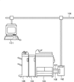
図1は、本実施形態を示す画像形成装置を含む印刷システムの構成を説明する図である。本例は、画像形成装置に接続された外部装置を介してデータ処理装置であるクライアントコンピュータ(PC)と通信するシステム例である。本実施形態に示す印刷システムは、画像形成されたシートに対して、後処理部材を交換して異なる後処理を実行する画像形成装置及び該画像形成装置と通信する情報処理装置としての後述するPDLコントローラ102を備えている。
<System configuration>
FIG. 1 is a diagram illustrating a configuration of a printing system including an image forming apparatus showing the present embodiment. This example is a system example of communicating with a client computer (PC) which is a data processing device via an external device connected to the image forming device. The printing system shown in the present embodiment is an image forming apparatus for performing different post-processing by exchanging post-processing members on an image-formed sheet, and a PDL described later as an information processing apparatus communicating with the image forming apparatus. It has a
図1において、クライアントコンピュータ(PC)101は、ユーザが指示するアプリケーションを実行して、所定のページ記述言語に準拠する印刷情報(PDLデータ)を生成する。
PDLコントローラ102は、例えばイーサネット(登録商標)ケーブルで構成されるネットワーク106を介して、PC101が生成したPDLデータを解析して、画像形成装置103が処理可能なジョブを出力する。なお、画像形成装置103は、プリンタとしてもコピー機としても使用できるように、リーダスキャナと原稿自動送り装置が装着可能に構成されている。
後処理装置104は、画像形成装置103から排出されたメディア(シート)に対して、シート単位の後処理を施すための装置である。フィニッシャー105は、後処理装置104の下流側に接続され、画像形成装置103から排紙されるシート束に対してステープル、シフト、中綴じ製本の機能を有している。
In FIG. 1, the client computer (PC) 101 executes an application instructed by a user to generate print information (PDL data) conforming to a predetermined page description language.
The
The
クライアントコンピュータ101とPDLコントローラ102はネットワーク106に接続されている。ケーブル107はPDLコントローラ102と画像形成装置103との間でPDLデータの印刷に関わる制御信号を双方向にやり取りする。画像転送用ビデオケーブル108は、PDLコントローラ102と画像形成装置103との間で画像情報であるビデオ信号をやり取りする。
The
<印刷装置とPDLコントローラの構成>
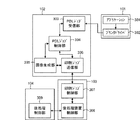
図2は、図1に示した印刷システムの構成を示すブロック図である。本例に示す印刷システムにおいて、画像形成装置103はコントローラ201、プリンタエンジン202、スキャナ219、操作部220から構成される。以下、各構成の詳細について説明する。
<Configuration of printing device and PDL controller>
FIG. 2 is a block diagram showing a configuration of the printing system shown in FIG. In the printing system shown in this example, the
PDLコントローラ102において、CPU203は、システムバス209を介してPDLコントローラ各部の制御、演算、及び記憶装置に格納されたプログラムの実行を行う。メモリ204はPDLデータの画像展開時の一時記憶領域、およびワークメモリとして使用される。ハードディスクドライブHDD205は大容量の記憶装置であり、CPU203により実行される各種制御プログラムを格納している。また、ハードディスクドライブHDD205は処理されるデータの一時的な記憶領域や保存領域としても使用される。
ネットワークインタフェース206はネットワーク106を介してクライアントコンピュータ101などの他の装置と通信を行う。PDL制御インタフェース207もネットワークインタフェース206と同様のネットワークインタフェースであるが、PDL印刷処理の制御を行い、画像形成装置103との間で制御コマンドの送受信を行う。
In the
The
コントローラ201において、CPU210はシステムバス216を介して画像形成装置各部の制御、演算、及び記憶装置に格納されたプログラムの実行を行う。メモリ211は印刷装置動作時における一時記憶領域、およびワークメモリとして使用される。ハードディスクドライブ(HDD)213は大容量の記憶装置であり、CPU210により実行される各種制御プログラムを格納している。また、HDD213は処理されるデータの一時的な記憶領域や保存領域として使用される。
PDL制御インタフェース212は、プリンタエンジン202で印刷するためのPDL印刷処理の制御を行いPDLコントローラ102との間で制御コマンドの送受信を行う。
In the
The
エンジンインタフェース(エンジンI/F)214は、プリンタエンジン202との通信制御を司る。プリンタエンジン202と後処理装置104、フィニッシャ105は専用ケーブルで接続されている。スキャナ219、操作部220はリーダインタフェース217によって、システムバス216を介してコントローラ201と接続されている。
The engine interface (engine I / F) 214 controls communication with the
<ソフトウェアモジュール構成>
図3は、図2に示した印刷システムのソフトウェアモジュールを示すブロック図である。
図3において、アプリケーション301とプリンタドライバ302はクライアントコンピュータ101の不図示のハードディスクから不図示のメモリに展開されクライアントコンピュータ101内の不図示のCPU上で実行される。アプリケーション301はDTPなどの文書作成アプリケーションでアプリケーション上の印刷設定でプリンタドライバ302を介してPDLデータが生成され、PDLコントローラ102に送信される。
<Software module configuration>
FIG. 3 is a block diagram showing a software module of the printing system shown in FIG.
In FIG. 3, the
PDLジョブ受信部303、PDLジョブ制御部304、画像生成部305、印刷ジョブ送信部306は、PDLコントローラ102のメモリ204に展開され、プログラムにより呼び出されてCPU203上で実行される。
PDLジョブ受信部303は、PC101から送信されたPDLジョブを受信する。PDLジョブ制御部304は、受信したPDLジョブのPDLデータを解析し、PDLジョブの制御を行う。
The PDL
The PDL
画像生成部305は、PDLデータを展開し、画像データを生成する。印刷ジョブ送信部306はPDLジョブ制御部304が解析した結果に基づき画像形成装置103へ画像生成部305が生成した画像データの送信や、画像形成装置103や後処理装置104の機器情報を取得するコマンドの送信を行う。ここで、画像形成装置103から取得する機器情報には、シート後処理を行う後処理部材(ダイ部材(クリースダイ、パンチダイ))の情報が含まれる。
The
印刷ジョブ制御部307は、印刷装置103のメモリ211に展開され、プログラムより呼び出されてCPU210上で実行される。印刷ジョブ制御部307は印刷ジョブ送信部306から送信された印刷画像データと印刷ジョブに対するプリンタエンジンの制御コマンドや機器情報取得コマンドのエンジンI/F214を介したプリンタエンジン202への送信や、機器情報取得要求に対する返信をする。
後処理装置制御部308は不図示のプリントエンジン202のメモリに展開され、プログラムより呼び出されて不図示のCPU上で実行される。後処理制御部309は不図示の後処理装置104のメモリ上に展開され、プログラムより呼び出されて不図示のCPU上で実行される。
The print
The post-processing
後処理装置制御部308は、印刷ジョブ制御部307からの制御コマンドに基づき、後処理制御部309に後処理命令を送信したり、後処理装置104のダイ情報や装置の状態通知を受信し印刷ジョブ制御部307に通知したりする。後処理制御部309は後処理を実行するとともにダイの状態やドアの開閉など後処理装置104の状態を後処理制御部308に通知する。
The post-processing
<後処理装置>
図4は、図1に示した後処理装置104の構成を示す断面図である。なお、後処理装置104は、画像形成されたシートに対して、後述する後処理部材を交換して異なる後処理を実行可能に構成されている。
図4において、ストレートパス401は、上流側から搬送されてきたメディアを下流側へ搬送するパスである。本実施例においては、画像形成装置103から受け取ったメディアを、フィニッシャ装置105へ搬送する。
<Post-processing device>
FIG. 4 is a cross-sectional view showing the configuration of the
In FIG. 4, the
搬送パス402は、後処理を行う対象となるメディアを搬送するための搬送パスである。フラッパ403は、画像形成装置103から搬送されてきたメディアを、ストレートパス401、もしくは搬送パス402に振り分けるものである。フラッパ403は、揺動軸を中心に揺動可能に構成され、メディアの搬送方向を規定する。フラッパ403が、図中時計回りの方向に揺動しているときは、メディアはストレートパス401に搬送され、図中反時計回りの方向に揺動しているときは、メディアは搬送パス402に搬送される。
The
後処理用ダイ404は、メディアに後処理を施すためのダイであり、後処理の施すための刃405を有している。本実施例において、後処理用ダイ404は、クリース(筋付け)用ダイ、パンチ用ダイの2種類が存在する。そして、ダイの種類により、刃405の形状は異なる。たとえば、クリース(筋付け)用ダイの場合は、刃405はメディアを切断しないために丸みを帯びた刃になっている。パンチ用ダイの場合は、刃405は、丸い穿孔を穿つための刃が直列に複数配置されている。
The
このような後処理用ダイ404は、後処理装置104に着脱可能であり、センサ(不図示)により、後処理用ダイ404が、後処理装置104に装着されているか否かを検知可能である。さらに、センサ(不図示)により、装着されているダイの種類がパンチャーなのかクリ―サーなのかを認識し、画像形成装置103に通知する。圧力装置406は、後処理用ダイ404に圧力を加えるための装置である。土台407は、刃405を受けるための土台である。搬送速度制御ユニット408は、メディアの搬送速度を規定の速度に制御するユニットであり、ユニット内部にメディアの搬送速度を検知するためのセンサを有している。検知センサ409は、搬送されているメディアの先端を検知するためのセンサである。
Such a
後処理装置104が、メディアに対して後処理を施す場合は、以下のような動作を行う。まず、搬送速度制御ユニット408は、メディアの搬送速度を検知するセンサを有しており、搬送パス402を通過するメディアの搬送速度を規定の速度になるように、加速もしくは減速する。そして、規定の速度で搬送されているメディアの先端が、検知センサ409で検知されると、圧力装置406は、後処理用ダイ404に対して、図中上方から下方に向かって圧力を加える。
When the
圧力装置406にて、後処理用ダイ404に加えられた圧力は、刃405に伝えられる。そして、刃405は、図中上方から下方へ移動し、刃405と土台407で、メディアを挟むことでクリース(筋付け)、パンチなどの後処理を実現する。
The pressure applied to the
<クリース設定ジョブの印刷>
クリース処理を設定して印刷する方法を図5、図7と図6のフローチャートを用いて説明する。図6はPDLコントローラ102が実行する処理で、メモリ204に展開されたプログラムによりCPU203が実行する。
<Printing crease setting job>
A method of setting the crease process and printing will be described with reference to the flowcharts of FIGS. 5, 7, and 6. FIG. 6 shows a process executed by the
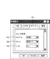
図5は、図1に示したPC101上で表示されるUI画面を示す図である。本例は、クライアントコンピュータ101上にインストールされたプリンタドライバ302が提供する印刷設定画面のうち、選択されたタブが仕上げの場合に表示される画面に対応する。
FIG. 5 is a diagram showing a UI screen displayed on the
図5において、仕上げタブ501は仕上げ設定を行う際に選択される。ステープル502はフィニッシャー105で行うステープルの綴じ方を設定する。ここでは「中綴じ」が設定されている。クリース503はクリース処理が施されるシートとして、「最終シート」が設定された状態を示す。パンチ504はパンチ処理として、パンチ処理は「なし」が設定された状態を示す。
なお、印刷設定を確定後、PC101上のアプリケーション301はクリース処理設定された印刷ジョブをプリンタドライバ302からPDLコントローラ102に送信する。
In FIG. 5, the
After confirming the print settings, the
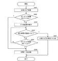
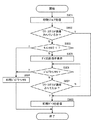
図6は、本実施形態を示す情報処理装置(PDLコントローラ102)の制御方法を説明するフローチャートである。本例は、PC101上のアプリケーション301からクリース処理設定された印刷ジョブをPDLコントローラ102が受信した際の処理に対応する。なお、各ステップは、PDLコントローラ102のCPU203が記憶された制御プログラムを実行することで実現される。
FIG. 6 is a flowchart illustrating a control method of the information processing device (PDL controller 102) showing the present embodiment. This example corresponds to the processing when the
印刷ジョブがPDLコントローラ102に送信されると本処理を開始して、S601でPDLジョブ受信部303は、送信された印刷ジョブをネットワーク106を介して受信する。S602ではPDLジョブ制御部304は、画像形成装置103と通信して、画像形成装置103に接続された後処理装置104に装着されているダイの種別(後処理条件)が指定されたクリースダイと一致しているかを判断する。
なお、PDLジョブ制御部304は印刷ジョブ送信部306を介して後処理装置104のダイ種別情報を画像形成装置103から取得し、PDLジョブ制御部304はその状態をメモリ204上で保持する。
本実施形態の画像形成装置は、後処理装置104でダイ部材を使用する後処理が指定された印刷ジョブを受信した場合、印刷ジョブで指定された後処理に対応したダイ部材が後処理装置104に装着されていない状態でも、印刷ジョブを実行する構成となっている。即ち、指定された後処理が実行されずに画像形成されたシートが排出される。
When the print job is transmitted to the
The PDL
In the image forming apparatus of the present embodiment, when the
図14は、PDLコントローラ102と画像形成装置103との通信処理を説明する図である。以下、図14に示す通信例を用いてPDLコントローラ102の後処理装置104のダイ情報取得処理の詳細を説明する。
図14では、PDLコントローラ102の印刷ジョブ送信部306のコマンド送受信と、画像形成装置103の印刷ジョブ制御部307のコマンド送受信とのやり取りを示す。
FIG. 14 is a diagram illustrating communication processing between the
FIG. 14 shows the exchange between the command transmission / reception of the print
PDLコントローラ102の起動時(1)
印刷ジョブ送信部306はインタフェースの初期化をするために、「I/F初期化要求」を送信し、印刷ジョブ制御部307から「OK」を受信すると「ダイ情報取得」を送信する。印刷ジョブ制御部307は「OK」の返信でダイ情報を通知する。ダイ情報には「ダイなし」、「パンチ」、「クリース」がある。
When the
The print
後処理装置104の前ドアが開閉されたとき(2)
印刷ジョブ制御部307は後処理装置104の前ドアが開くと印刷ジョブ送信部306に「機器状態通知」を送信し、前ドアが開いたことを通知する。次に、後処理装置104の前ドアが閉じると印刷ジョブ制御部307は印刷ジョブ送信部306に「機器状態通知」を送信し、前ドアが閉じたことを通知する。印刷ジョブ送信部306はこの一連の通知を受信すると「ダイ情報取得」を送信し、印刷ジョブ制御部307の「OK」の返信からダイ情報を更新する。
When the front door of the
When the front door of the
画像形成装置103が省電力状態(スリープモード)から復帰したとき(3)
印刷ジョブ制御部307は画像形成装置103が省電力状態から復帰すると「システム状態通知」を送信して印刷ジョブ送信部306に通知する。印刷ジョブ送信部306は「システム状態通知」を受信し、送信理由が省電力状態からの復帰である場合には「ダイ情報取得」を送信し、印刷ジョブ制御部307の「OK」の返信からダイ情報を更新する。
When the
When the
後処理装置104に装着されているダイがクリースダイである場合はS606で、印刷ジョブ送信部306はPDLデータから画像生成部305がラスタライズした画像データと画像形成装置への制御コマンドを画像形成装置103の印刷ジョブ制御部307に送信する。なお、図中のS606では、ラスタライズした画像データと画像形成装置への制御コマンドとを合わせて印刷データと記す。
If the die mounted on the
図7に示すUI画面は、クライアントコンピュータ101上の不図示のPDLコントローラ102の印刷ジョブを管理するジョブ管理アプリケーション上に表示される警告メッセージ701を示した例である。
ここで、図6の説明に戻り、上記S602で、上記通信により後処理装置104にクリースダイが装着されていないとPDLジョブ制御部304が判断した場合、S603で、PDLジョブ制御部304はクライアントコンピュータ101上のプリンタドライバ302または不図示のPDLコントローラ102の印刷ジョブを管理するジョブ管理アプリケーションに「クリースダイ交換指示」のステータスを通知し、ジョブアプリケーションは、図7に一例を示すクリースダイへの交換を促すメッセージ701をPC101上の画面に表示する。
The UI screen shown in FIG. 7 is an example showing the
Here, returning to the description of FIG. 6, when the PDL
S604では、PDLジョブ制御部304はS603の表示をしてからの時間があらかじめ設定した待ち時間を経過したかを判断する。この待ち時間はPDLコントローラの不図示の機器設定画面より設定が可能であり、デフォルトは5分となっている。
S604において、待ち時間が経過していないとPDLジョブ制御部304が判断した場合、PDLジョブ制御部304は処理をS605に進める。
S605では、PDLジョブ制御部304は後処理装置104にクリースダイが装着されたかどうかを判断し、クリースダイが装着されていないとPDLジョブ制御部304が判断した場合、PDLジョブ制御部304は処理をS604に戻す。
一方、S604で待ち時間が経過したとPDLジョブ制御部304が判断した場合には、PDLジョブ制御部304は処理をS607に進める。S607では、PDLジョブ制御部304は、PC101からの応答に従い、印刷ジョブの印刷を送信せずに印刷ジョブをHDD205に保存するか、印刷ジョブをキャンセル(取消)して、本処理を終了する。
なお、S607で印刷ジョブを送信しないときに保存するか、キャンセルするかのどちらの動作をするかは、前述の機器設定画面で設定された動作に従う。
In S604, the PDL
If the PDL
In S605, the PDL
On the other hand, when the PDL
Whether to save or cancel the print job when the print job is not sent in S607 follows the operation set on the above-mentioned device setting screen.
一方、S605でクリースダイが装着されているとPDLジョブ制御部304が判断した場合は、PDLジョブ制御部304は処理をS606に進める。S606で、印刷ジョブ送信部306はPDLデータから画像生成部305がラスタライズした画像データと画像形成装置103への制御コマンドを画像形成装置103の印刷ジョブ制御部307に送信して、本処理を終了する。
なお、印刷ジョブ制御部307は、後処理設定を後処理装置制御部308に指示し、後処理装置制御部308は、後処理制御部309にクリース処理を指示することで、指示された後処理設定に基づくクリース処理を実行し印刷ジョブを出力する。
On the other hand, when the PDL
The print
第1実施形態によれば、情報処理装置が後処理を指定した印刷ジョブを受信した際に、後処理装置に異なる後処理部材が装着されている状態では、印刷ジョブがキャンセルまたは保存される状態に遷移させることができる。したがって、後処理部材の交換等の作業がなされていない場合、情報処理装置はPC等から印刷ジョブを受信しても、印刷ジョブに従う印刷データを画像形成装置に送信しないため、指定された後処理が実行されていないシートを排紙してしまうことを防止できる。 According to the first embodiment, when the information processing apparatus receives a print job for which post-processing is specified, the print job is canceled or saved in a state where a different post-processing member is attached to the post-processing apparatus. Can be transitioned to. Therefore, if the post-processing member is not replaced, the information processing device does not send the print data according to the print job to the image forming device even if the information processing device receives the print job from the PC or the like. Therefore, the specified post-processing It is possible to prevent the sheet that has not been executed from being ejected.
〔第2実施形態〕
<後処理印刷ジョブ送信設定>
[Second Embodiment]
<Post-processing print job transmission settings>
上記第1実施形態ではPDLコントローラ102が画像形成装置103にクリース処理の印刷ジョブを送信するときに所定の待ち時間を設定し、その時間が経過するまでにクリースダイが後処理装置104に装着されない場合にはクリース処理の印刷ジョブをPDLコントローラ102に保存する、もしくはキャンセルを行った。
In the first embodiment, when the
これに対して、印刷ジョブに適切な後処理装置104のダイが装着されていない場合の印刷ジョブの送信動作をPDLコントローラ102の機器設定で行って、その後で処理印刷ジョブ送信設定に従ってクリース処理の印刷ジョブを処理するように構成してもよい。以下のその実施形態について詳述する。
On the other hand, when the
図8は、本実施形態を示す情報処理装置の制御方法を説明するフローチャートである。本例は、PC101上のアプリケーション301はクリース処理設定された印刷ジョブを受信した際の処理に対応する。なお、各ステップは、PDLコントローラ102のCPU203が記憶された制御プログラムを実行することで実現される。
FIG. 8 is a flowchart illustrating a control method of the information processing apparatus showing the present embodiment. In this example,
プリンタドライバ302で設定された印刷ジョブがPDLコントローラ102に送信されると、S801でPDLジョブ受信部303は、送信された印刷ジョブを受信する。S802ではPDLジョブ制御部304は、後処理装置104に装着されているダイの種別がクリースダイであるかを確認する。PDLジョブ制御部304は後処理装置のダイ種別情報を第1実施形態と同様のタイミングで画像形成装置103から取得し、PDLジョブ制御部304はその状態を保持している。
When the print job set by the
ここで、後処理装置104に装着されているダイがクリースダイであるとPDLジョブ制御部304が判断した場合は、PDLジョブ制御部304は処理をS808に進める。そして、S808で、印刷ジョブ送信部306はPDLデータから画像生成部305がラスタライズした画像データと画像形成装置への制御コマンドを画像形成装置103の印刷ジョブ制御部307に送信して、本処理を終了する。
Here, when the PDL
一方、S802で、PDLジョブ制御部304が後処理装置104にクリースダイが装着されていないと判断した場合、PDLジョブ制御部304は処理をS803進める。
S803で、PDLジョブ制御部304は、後処理印刷ジョブ送信モードの設定を確認する。なお、本実施形態では、後処理印刷ジョブ送信設定モードは不図示のPDLコントローラ102の機器設定で設定するが、印刷ジョブに適切な後処理装置104のダイが装着されていない場合に、適切なダイに交換されるのを待つことなくジョブをキャンセルする「キャンセルモード」と適切なダイに交換されるのを待つ「ウエイトモード」がある。
S803で後処理印刷ジョブ送信設定が「キャンセルモード」に設定されているとPDLジョブ制御部304が判断した場合には、PDLジョブ制御部304は処理をS804に進める。
S804でPDLジョブ制御部304は印刷ジョブをキャンセルし、本印刷処理を終了する。
一方、S803で後処理印刷ジョブ送信設定が「ウエイトモード」であるとPDLジョブ制御部304が判断した場合、PDLジョブ制御部304は処理をS805に進める。
On the other hand, in S802, when the PDL
In S803, the PDL
When the PDL
In S804, the PDL
On the other hand, when the PDL
ここで、S805において表示する警告画面の内容について図9を参照して、説明する。
図9に示すUI画面は、クライアントコンピュータ101上の不図示のPDLコントローラ102の印刷ジョブを管理するジョブ管理アプリケーション上に表示される警告メッセージ画面を示した例である。
図9において、警告画面では、クリースダイへの交換を促すメッセージ901と印刷ジョブをキャンセルするキャンセルボタン902とを表示した状態に対応する。
S805で、PDLジョブ制御部304はPC101上のプリンタドライバ302または不図示のPDLコントローラ102の印刷ジョブを管理するジョブ管理アプリケーションに「クリースダイ交換指示」のステータスを通知し、ジョブアプリケーションはクリースダイ交換のメッセージ901を表示装置に表示する。次に、PDLジョブ制御部304は、処理をS806へ進める。
Here, the contents of the warning screen displayed in S805 will be described with reference to FIG.
The UI screen shown in FIG. 9 is an example showing a warning message screen displayed on a job management application that manages a print job of the PDL controller 102 (not shown) on the
In FIG. 9, the warning screen corresponds to a state in which a
In S805, the PDL
S806ではPDLジョブ制御部304はキャンセルボタン902が押下されたかを判断し、キャンセルボタン902が押下されたと判断した場合、PDLジョブ制御部304は処理をS804に戻す。
一方、S806で、キャンセルボタン902が押下されていないとPDLジョブ制御部304が判断した場合、処理をS807に進める。
S807ではPDLジョブ制御部304は後処理装置104にクリースダイが装着されたかどうかを判断し、クリースダイが装着されていないとPDLジョブ制御部304が判断した場合、PDLジョブ制御部304は処理をS806に戻す。
In S806, the PDL
On the other hand, if the PDL
In S807, the PDL
一方、S807でクリースダイが装着されているとPDLジョブ制御部304が判断した場合、PDLジョブ制御部304は処理をS808に進める。
S808で、印刷ジョブ送信部306はPDLデータから画像生成部305がラスタライズした画像データと画像形成装置への制御コマンドを画像形成装置103の印刷ジョブ制御部307に送信して、本処理を終了する。なお、図中のS808では、ラスタライズした画像データと画像形成装置への制御コマンドとを合わせて印刷データと記す。
この後、印刷ジョブ制御部306は後処理設定を後処理装置制御部308に指示し、後処理制御部309は指示された後処理設定に基づいてクリース処理を実行し印刷ジョブを出力する。
On the other hand, when the PDL
In S808, the print
After that, the print
第2実施形態によれば、情報処理装置が後処理を指定した印刷ジョブを受信した際に、後処理装置に異なる後処理部材が装着されている状態では、印刷ジョブに従う印刷データが像形成装置に送信されない。従って、指定された後処理が実行されていないシートを排紙してしまうことを防止できる。
また、ユーザは印刷ジョブをキャンセルするか否かを直ちに決定することができる。
According to the second embodiment, when the information processing apparatus receives a print job for which post-processing is specified, the print data according to the print job is image-forming apparatus in a state where different post-processing members are attached to the post-processing apparatus. Not sent to. Therefore, it is possible to prevent the sheet that has not been subjected to the designated post-processing from being ejected.
In addition, the user can immediately decide whether or not to cancel the print job.
〔第3実施形態〕
<ダイ交換指示画面の表示タイミング>
[Third Embodiment]
<Display timing of die replacement instruction screen>
第1、第2実施形態では単独の印刷ジョブの制御について説明したが、複数の印刷ジョブを連続して印刷する場合のダイ交換指示画面の表示タイミングについて説明する。 In the first and second embodiments, the control of a single print job has been described, but the display timing of the die replacement instruction screen when printing a plurality of print jobs in succession will be described.
図10は、複数の印刷ジョブを送信するタイミングを説明するチャートである。本実施形態において、PDLコントローラ102は印刷ジョブを連続して画像形成装置103に送信することが可能である。
図10において、ジョブ1からジョブ5に対応する印刷ジョブ1001〜1005でPDLコントローラ102が連続して印刷する場合において、現在、ジョブ1は画像形成装置103で印刷中であり、ジョブ2とジョブ3はPDLコントローラ102から画像形成装置103に送信済みの印刷ジョブであり、画像形成装置103のメモリ211上に保持されている。
ジョブ4とジョブ5はPDLコントローラ102で未送信の印刷ジョブであり、PDLコントローラ102のメモリ204上に保持されている。
FIG. 10 is a chart illustrating timing for transmitting a plurality of print jobs. In the present embodiment, the
In FIG. 10, when the
この状態において、後処理装置104にクリースダイは装着されていないときにクリース処理のジョブ4を第2実施形態と同様にして印刷処理する場合を図8を参照して説明する。
PDLコントローラ102のPDLジョブ制御部304は、印刷処理が終了するまで送信済みのジョブが後処理装置104を使用するジョブかどうかを示す情報を保持する。
S805でPDLジョブ制御部304は先行する印刷ジョブ、ジョブ1、ジョブ2、ジョブ3が後処理装置104のパンチダイを使用しないジョブであると判断した場合には、即座に図9に示したメッセージ画面に基づくダイ交換指示を表示する。また、先行する印刷ジョブに後処理装置のパンチダイを使用する印刷ジョブがある場合にはそのジョブの印刷終了後にダイ交換指示を表示する。
例えばジョブ2がパンチダイを使用する印刷ジョブである場合、ジョブ2の印刷終了後にダイ交換指示を表示する。このときの印刷ジョブの状態を図11に示す。
In this state, a case where the
The PDL
When the PDL
For example, if job 2 is a print job that uses a punch die, a die replacement instruction is displayed after the print of job 2 is completed. The state of the print job at this time is shown in FIG.
また、ダイ交換指示の画面を先行する印刷ジョブがすべて印刷終了した後に表示するようにしてもよいが、その場合であっても先行する印刷ジョブの印刷中に紙なし、ジャムなどで印刷が中断したときに先行する印刷ジョブに後処理装置104のパンチダイを使用するジョブがない場合にはダイ交換指示画面を表示するようにしてもよい。
Further, the die replacement instruction screen may be displayed after all the preceding print jobs have finished printing, but even in that case, printing is interrupted due to no paper, jam, etc. during printing of the preceding print job. If there is no job that uses the punch die of the
本実施形態の印刷システムは商業印刷などのプロダクション用途を想定しており、オペレータが印刷ジョブを管理している場合に先行してダイの交換指示を表示することにより印刷ジョブのキャンセルやダイ交換のタイミングを調整できるというメリットがある。 The printing system of this embodiment is intended for production use such as commercial printing, and cancels a print job or replaces a die by displaying a die replacement instruction in advance when the operator manages the print job. There is an advantage that the timing can be adjusted.
〔第4実施形態〕
<ダイ名称(後処理部材の名称)によるジョブ送信の方法の制御>
[Fourth Embodiment]
<Control of job transmission method by die name (name of post-processing member)>
第1〜第3実施形態では後処理装置104のクリース処理の印刷ジョブの印刷方法について説明したが、後処理装置104のパンチ処理の印刷ジョブのPDLコントローラ102からの送信方法について説明する。
In the first to third embodiments, the printing method of the crease processing print job of the
これまで説明してきたように本実施例の印刷装置システムでは後処理装置104のダイがパンチダイであるかクリースダイであるかの装着情報をPDLコントローラ102は取得することができる。
しかしながら、実際にはパンチダイには多くの種類があり、パンチ穴の個数も刃を組み替えることで変更することが可能なものも存在する。画像形成装置103ではパンチダイについてはパンチ穴など具体的な種類を区別することはできないがパンチダイに名称を登録することは可能である。具体的にはパンチダイの名称を画像形成装置103の操作部220から入力し、後処理装置制御部308は装着されているパンチダイのシリアル番号の情報と入力された名称を関連付けて登録する。登録されたパンチダイの名称は操作部220で確認することができる。
As described above, in the printing apparatus system of the present embodiment, the
However, in reality, there are many types of punch dies, and there are some that can change the number of punch holes by rearranging the blades. In the
本実施例ではパンチダイの名称の付け方と印刷ジョブの送信制御を関連付け、パンチダイ名称によって印刷ジョブの送信を制御する。具体的にはパンチダイ名称に印刷ジョブとして使用する用紙サイズと用紙名の条件を記述したジョブ送信制御ルールを定義する。パンチダイ名称は、[制御対象]_[値]_[任意名]の形式となっている。 In this embodiment, the method of naming the punch die is associated with the print job transmission control, and the print job transmission is controlled by the punch die name. Specifically, a job transmission control rule that describes the conditions of the paper size and paper name used as a print job in the punch die name is defined. The punch die name is in the format of [control target] _ [value] _ [arbitrary name].
制御対象は用紙サイズの場合は「SZ」、用紙名のときは「PN」とする。値はパンチダイが使用するサイズまたは名称を入れる。例えば、パンチダイ名称を「SZ_A4_3H」とした場合は、ジョブ送信の制御ルールは「印刷ジョブの用紙サイズがA4またはA3以外のときは印刷ジョブを送信しないでダイの交換指示表示を行う」となる。「PN_コート紙5_22穴」とした場合は、「印刷ジョブで使用する用紙名がコート紙5以外のときは印刷ジョブを送信しないでダイの交換指示表示を行う」となる。 The control target is "SZ" for the paper size and "PN" for the paper name. The value is the size or name used by the punch die. For example, when the punch die name is "SZ_A4_3H", the job transmission control rule is "when the paper size of the print job is other than A4 or A3, the die replacement instruction is displayed without sending the print job". When "PN_coated paper 5_22 holes" is set, "when the paper name used in the print job is other than coated paper 5, the die replacement instruction is displayed without sending the print job".
図12は、本実施形態を示す情報処理装置の制御方法を説明するフローチャートである。本例は、PC101上のアプリケーション301はクリース処理設定された印刷ジョブを受信した際の処理に対応する。なお、各ステップは、PDLコントローラ102のCPU203が記憶された制御プログラムを実行することで実現される。
FIG. 12 is a flowchart illustrating a control method of the information processing apparatus showing the present embodiment. In this example,
第1実施形態と同様のプリンタドライバ302で502のステープルと503のクリースを「なし」に504のパンチを「左」に設定された印刷ジョブがPDLコントローラ102に送信されると、S1201でPDLジョブ受信部303は送信された印刷ジョブを受信する。S1202ではPDLジョブ制御部304は後処理装置104に装着されているダイの種別と登録されているパンチダイ名称と受信した印刷ジョブの用紙サイズ、用紙名とからダイの確認が必要であるかを判断する。PDLジョブ制御部304は後処理装置のダイ種別と登録されているパンチダイ名称を第1実施形態と同様のタイミングで画像形成装置103から取得し、PDLジョブ制御部304はその状態を保持している。
When a print job with 502 staples and 503 creases set to "none" and 504 punches set to "left" with the
後処理装置104に装着されているダイの名称が印刷ジョブで指定したダイ名称に一致しており、ダイの確認が必要ないとPDLジョブ制御部304が判断した場合は、PDLジョブ制御部304は処理をS1207に進める。S1207で、印刷ジョブ送信部306はPDLデータから画像生成部305がラスタライズした画像データと画像形成装置への制御コマンドを画像形成装置103の印刷ジョブ制御部307に送信する。なお、図中のS1207では、ラスタライズした画像データと画像形成装置への制御コマンドとを合わせて印刷データと記す。
If the name of the die mounted on the
後処理装置104のダイの名称が印刷ジョブで指定したダイ名称に一致しておらず、ダイの確認が必要であるとPDLジョブ制御部304が判断した場合、PDLジョブ制御部304は処理をS1203に進める。
図13はクライアントコンピュータ101上の不図示のPDLコントローラ102の印刷ジョブを管理するジョブ管理アプリケーション上に表示される警告メッセージ画面である。
図13に示すUI画面では、パンチダイの交換を促すメッセージ1301、印刷ジョブをキャンセルするキャンセルボタン1302を表示した状態を示している。
S1203でPDLジョブ制御部304はクライアントコンピュータ101上のプリンタドライバ302または不図示のPDLコントローラ102の印刷ジョブを管理するジョブ管理アプリケーションに「パンチダイ交換指示」のステータスを通知し、ジョブアプリケーションは901のパンチダイ交換を促すメッセージを表示する。
If the die name of the
FIG. 13 is a warning message screen displayed on the job management application that manages the print job of the PDL controller 102 (not shown) on the
The UI screen shown in FIG. 13 shows a state in which a
In S1203, the PDL
S1204ではPDLジョブ制御部304はキャンセルボタン1302が押下されたかを判断し、キャンセルボタンが押下されたとPDLジョブ制御部304が判断した場合には、PDLジョブ制御部304は処理をS1205に進め、キャンセルボタンが押下されていないとPDLジョブ制御部304が判断した場合には、PDLジョブ制御部304は処理をS1206に進める。
S1205でPDLジョブ制御部304は印刷ジョブをキャンセルし、PDLジョブ制御部304は印刷処理を終了する。
S1206ではPDLジョブ制御部304は、後処理装置104に印刷ジョブに使用できるパンチダイが装着されたかどうかを判断し、適切なパンチダイが装着されていないとPDLジョブ制御部304が判断した場合には、PDLジョブ制御部304は処理をS1204に戻す。
In S1204, the PDL
In S1205, the PDL
In S1206, the PDL
一方、S1206で適切なパンチダイが装着されているとPDLジョブ制御部304が判断した場合は、PDLジョブ制御部304は処理をS1207に進める。S1207では、印刷ジョブ送信部306はPDLデータから画像生成部305がラスタライズした画像データと画像形成装置への制御コマンドを画像形成装置103の印刷ジョブ制御部307に送信して、PDLジョブ制御部304は印刷処理を終了する。
この後、印刷ジョブ制御部306は後処理設定を後処理装置制御部308に指示し、後処理制御部309は指示された後処理設定に基づいてクリース処理を実行し印刷ジョブを出力する。
On the other hand, if the PDL
After that, the print
第4実施形態によれば、特定の後処理部材名称の後処理部材を用いて後処理を行う印刷ジョブを受信した際に、画像形成装置に異なる後処理部材の名称が装着されている状態では、印刷ジョブがキャンセルまたは保存される状態に遷移させることができる。
したがって、複数の種類が予定された後処理部材のうち、印刷ジョブで指定された後処理部材が一致しない状態では、受信した印刷ジョブに基づく印刷データが画像形成装置に送信されてしまうことを防止できる。
According to the fourth embodiment, when a print job for performing post-processing using a post-processing member with a specific post-processing member name is received, the image forming apparatus is equipped with a different name of the post-processing member. , The print job can be canceled or transitioned to the saved state.
Therefore, it is possible to prevent the print data based on the received print job from being transmitted to the image forming apparatus when the post-processing members specified in the print job do not match among the post-processing members of which a plurality of types are planned. it can.
本発明は、上述の実施形態の1以上の機能を実現するプログラムを、ネットワーク又は記憶媒体を介してシステムまたは装置に供給し、そのシステム又は装置のコンピュータにおける1つ以上のプロセッサがプログラムを読み出し実行する処理でも実現可能である。また、1以上の機能を実現する回路(例えばASIC)によっても実現可能である。 The present invention supplies a program that realizes one or more functions of the above-described embodiment to a system or device via a network or storage medium, and one or more processors in the computer of the system or device reads and executes the program. It can also be realized by the processing to be performed. It can also be realized by a circuit (for example, ASIC) that realizes one or more functions.
101 PC
102 PDLコントローラ
103 画像形成装置
104 後処理装置
105 フィニッシャ
304 PDLジョブ制御部
101 PC
102 PDL controller
103 Image forming device
104 Aftertreatment device
105 Finisher
304 PDL Job Control Unit
Claims (12)
前記画像形成装置から受信する後処理部材に関する情報に基づいて、前記画像形成装置へ送信するべき印刷ジョブに指定された後処理に対応する後処理部材が前記後処理装置に装着されていないと判断した場合、前記画像形成装置に対して前記印刷ジョブを送信しないよう制御する制御手段と、
前記印刷ジョブで指定された後処理に対応する後処理部材が装着されていない場合に、前記情報処理装置へ前記印刷ジョブを送信してきたデータ処理装置に対して前記後処理部材の変更を促す指示を送信するか、前記後処理部材の変更を待つことなく前記印刷ジョブをキャンセルするかを予め設定する設定手段と、を備え、
前記制御手段は、前記印刷ジョブで指定された後処理に対応する後処理部材が装着されていない場合に、前記設定手段により予め設定された内容に従って前記指示を送信するか前記印刷ジョブをキャンセルするかを決定することを特徴とする情報処理装置。 An information processing device that transmits a print job to an image forming device to which a post-processing device capable of performing different post-processing by exchanging post-processing members is connected to an image-formed sheet.
Based on the information about the post-processing member received from the image forming apparatus, it is determined that the post-processing member corresponding to the post-processing specified in the print job to be transmitted to the image forming apparatus is not attached to the post-processing apparatus. If so, a control means for controlling the image forming apparatus not to send the print job, and
An instruction to urge the data processing device that has transmitted the print job to the information processing device to change the post-processing member when the post-processing member corresponding to the post-processing specified in the print job is not mounted. Is provided , or a setting means for setting in advance whether to cancel the print job without waiting for the change of the post-processing member is provided .
When the post-processing member corresponding to the post-processing specified by the print job is not mounted, the control means transmits the instruction or cancels the print job according to the contents preset by the setting means. An information processing device characterized by determining whether or not .
前記制御手段は、前記パンチダイ或いは前記クリースダイへの交換を表す指示を送信することを特徴とする請求項3に記載の情報処理装置。 The post-treatment device can be equipped with a punch die for punching the sheet or a crease die for scoring the sheet as the post-treatment member.
The information processing apparatus according to claim 3, wherein the control means transmits an instruction indicating replacement with the punch die or the crease die.
前記制御手段は、前記印刷ジョブに指定された後処理条件に従う後処理部材名称と、前記画像形成装置から取得する装着されている後処理部材の後処理部材名称とが一致するかどうかを判断して、前記画像形成装置に対して前記印刷ジョブに基づく印刷データを送信するかどうかを制御する制御手段を備えることを特徴とする請求項1または2に記載の情報処理装置。 The name of the post-processing member mounted on the image forming apparatus is registered in the image forming apparatus.
The control means determines whether or not the name of the post-processing member according to the post-processing conditions specified in the print job matches the name of the post-processing member of the mounted post-processing member acquired from the image forming apparatus. The information processing apparatus according to claim 1 or 2, further comprising a control means for controlling whether or not to transmit print data based on the print job to the image forming apparatus.
前記情報処理装置は、
前記画像形成装置から受信する後処理部材に関する情報に基づいて、前記画像形成装置へ送信するべき印刷ジョブに指定された後処理に対応する後処理部材が前記後処理装置に装着されていないと判断した場合、前記画像形成装置に対して前記印刷ジョブを送信しないよう制御する制御手段と、
前記印刷ジョブで指定された後処理に対応する後処理部材が装着されていない場合に、前記情報処理装置へ前記印刷ジョブを送信してきたデータ処理装置に対して前記後処理部材の変更を促す指示を送信するか、前記後処理部材の変更を待つことなく前記印刷ジョブをキャンセルするかを予め設定する設定手段と、を備え、
前記制御手段は、前記印刷ジョブで指定された後処理に対応する後処理部材が装着されていない場合に、前記設定手段により予め設定された内容に従って前記指示を送信するか前記印刷ジョブをキャンセルするかを決定することを特徴とする印刷システム。 An image forming device to which a post-processing device capable of performing different post-processing by exchanging post-processing members is connected to the image-formed sheet, and an information processing device for transmitting a print job to the image forming device. It is a printing system that has
The information processing device
Based on the information about the post-processing member received from the image forming apparatus, it is determined that the post-processing member corresponding to the post-processing specified in the print job to be transmitted to the image forming apparatus is not attached to the post-processing apparatus. If so, a control means for controlling the image forming apparatus not to send the print job, and
An instruction to urge the data processing device that has transmitted the print job to the information processing device to change the post-processing member when the post-processing member corresponding to the post-processing specified in the print job is not mounted. Is provided , or a setting means for setting in advance whether to cancel the print job without waiting for the change of the post-processing member is provided .
When the post-processing member corresponding to the post-processing specified by the print job is not mounted, the control means transmits the instruction or cancels the print job according to the contents preset by the setting means. A printing system characterized by determining whether or not .
前記画像形成装置から受信する後処理部材に関する情報に基づいて、前記画像形成装置へ送信するべき印刷ジョブに指定された後処理に対応する後処理部材が前記後処理装置に装着されていないと判断した場合、前記画像形成装置に対して前記印刷ジョブを送信しないよう制御する制御工程と、
前記印刷ジョブで指定された後処理に対応する後処理部材が装着されていない場合に、前記情報処理装置へ前記印刷ジョブを送信してきたデータ処理装置に対して前記後処理部材の変更を促す指示を送信するか、前記後処理部材の変更を待つことなく前記印刷ジョブをキャンセルするかを予め設定する設定工程と、
前記印刷ジョブで指定された後処理に対応する後処理部材が装着されていない場合に、前記設定工程により予め設定された内容に従って前記指示を送信するか前記印刷ジョブをキャンセルするかを決定する決定工程と、を備えることを特徴とする情報処理装置の制御方法。 It is a control method of an information processing device that sends a print job to an image forming device to which a post-processing device capable of performing different post-processing by exchanging post-processing members is connected to an image-formed sheet. ,
Based on the information about the post-processing member received from the image forming apparatus, it is determined that the post-processing member corresponding to the post-processing specified in the print job to be transmitted to the image forming apparatus is not attached to the post-processing apparatus. If this is the case, a control step that controls the image forming apparatus not to send the print job, and
An instruction to urge the data processing device that has transmitted the print job to the information processing device to change the post-processing member when the post-processing member corresponding to the post-processing specified in the print job is not mounted. And a setting process in which the printing job is canceled without waiting for the change of the post-processing member.
When the post-processing member corresponding to the post-processing specified in the print job is not mounted, a determination is made to determine whether to send the instruction or cancel the print job according to the contents preset by the setting step. control method for an information processing apparatus characterized by comprising: a step.
Priority Applications (2)
| Application Number | Priority Date | Filing Date | Title |
|---|---|---|---|
| JP2016220401A JP6812208B2 (en) | 2016-11-11 | 2016-11-11 | Information processing equipment, printing system, information processing equipment control method, and program |
| US15/807,432 US10577212B2 (en) | 2016-11-11 | 2017-11-08 | Information processing apparatus for controlling execution of print job in which post-processing is designated |
Applications Claiming Priority (1)
| Application Number | Priority Date | Filing Date | Title |
|---|---|---|---|
| JP2016220401A JP6812208B2 (en) | 2016-11-11 | 2016-11-11 | Information processing equipment, printing system, information processing equipment control method, and program |
Publications (3)
| Publication Number | Publication Date |
|---|---|
| JP2018077753A JP2018077753A (en) | 2018-05-17 |
| JP2018077753A5 JP2018077753A5 (en) | 2019-12-26 |
| JP6812208B2 true JP6812208B2 (en) | 2021-01-13 |
Family
ID=62107204
Family Applications (1)
| Application Number | Title | Priority Date | Filing Date |
|---|---|---|---|
| JP2016220401A Active JP6812208B2 (en) | 2016-11-11 | 2016-11-11 | Information processing equipment, printing system, information processing equipment control method, and program |
Country Status (2)
| Country | Link |
|---|---|
| US (1) | US10577212B2 (en) |
| JP (1) | JP6812208B2 (en) |
Families Citing this family (3)
| Publication number | Priority date | Publication date | Assignee | Title |
|---|---|---|---|---|
| JP7275934B2 (en) * | 2019-07-02 | 2023-05-18 | コニカミノルタ株式会社 | Image forming apparatus, image forming method, and image forming program |
| JP7290078B2 (en) | 2019-07-05 | 2023-06-13 | コニカミノルタ株式会社 | Image forming apparatus and image forming system |
| JP7347119B2 (en) | 2019-10-28 | 2023-09-20 | コニカミノルタ株式会社 | Image forming device |
Family Cites Families (9)
| Publication number | Priority date | Publication date | Assignee | Title |
|---|---|---|---|---|
| JP4508934B2 (en) * | 2005-04-26 | 2010-07-21 | キヤノン株式会社 | Information processing apparatus, information processing method, and program |
| JP2008224724A (en) * | 2007-03-08 | 2008-09-25 | Kyocera Mita Corp | Image forming apparatus |
| JP2010277324A (en) * | 2009-05-28 | 2010-12-09 | Fuji Xerox Co Ltd | Print instruction device and print instruction program |
| JP2010280060A (en) * | 2009-06-02 | 2010-12-16 | Ricoh Co Ltd | Image forming apparatus, method and program for controlling image formation, and recording medium |
| JP5610891B2 (en) * | 2010-07-20 | 2014-10-22 | キヤノン株式会社 | Printing system and information processing method |
| JP6329389B2 (en) * | 2014-02-25 | 2018-05-23 | キヤノン株式会社 | Image forming system and image forming apparatus |
| JP6521577B2 (en) * | 2014-06-16 | 2019-05-29 | キヤノン株式会社 | Image forming apparatus and control method thereof |
| JP6391357B2 (en) | 2014-08-11 | 2018-09-19 | キヤノン株式会社 | Printing system, printing system control method and program |
| JP2017213885A (en) * | 2016-05-30 | 2017-12-07 | ミュラー・マルティニ・ホルディング・アクチエンゲゼルシヤフト | Method and device for controlling printing subsequent processing facility |
-
2016
- 2016-11-11 JP JP2016220401A patent/JP6812208B2/en active Active
-
2017
- 2017-11-08 US US15/807,432 patent/US10577212B2/en active Active
Also Published As
| Publication number | Publication date |
|---|---|
| US10577212B2 (en) | 2020-03-03 |
| US20180134509A1 (en) | 2018-05-17 |
| JP2018077753A (en) | 2018-05-17 |
Similar Documents
| Publication | Publication Date | Title |
|---|---|---|
| KR101611656B1 (en) | Sheet processing apparatus, control method of sheet processing apparatus, and storage medium | |
| US9020413B2 (en) | Selectively changing printing order of print data depending on selected binding process | |
| JP6812208B2 (en) | Information processing equipment, printing system, information processing equipment control method, and program | |
| JP6521577B2 (en) | Image forming apparatus and control method thereof | |
| US10606524B2 (en) | Image forming apparatus, image forming system, information processing apparatus, control method for an information processing apparatus, and non-transitory computer-readable storage medium with determination of mounted punch die | |
| JP2016016583A (en) | Printing system, control device, control method, and program | |
| JP2011059344A (en) | Image forming apparatus, method of controlling image forming apparatus, and program | |
| JP4779390B2 (en) | Image forming apparatus control system and image forming apparatus | |
| US8982402B2 (en) | Image forming system and image forming system communication control method | |
| US10209663B2 (en) | Image forming apparatus, control method for image forming apparatus, and non-transitory computer-readable storage medium | |
| JP5677071B2 (en) | Sheet processing apparatus, sheet processing method, and program | |
| JP4983235B2 (en) | Image processing apparatus, image processing system, and image processing program | |
| JP6473399B2 (en) | Information processing apparatus, information processing apparatus control method, and storage medium | |
| JP2015168235A (en) | Sheet processing device, information processing device and control method and program thereof | |
| JP6800746B2 (en) | Image forming apparatus, control method of image forming apparatus, and program | |
| JP4872995B2 (en) | Image processing apparatus, image forming system, and image processing program | |
| JP2006267610A (en) | Image forming apparatus, system and control method | |
| JP6745591B2 (en) | System having printing device and print control device | |
| JP2015168234A (en) | Sheet processing device, information processing device and control method and program thereof | |
| JP7475929B2 (en) | Print processing system, printing device and control method thereof, information processing device and control method thereof | |
| JP6743239B2 (en) | System, post-processing apparatus and control method thereof | |
| JP2016084184A (en) | Control method for image formation system comprising image formation apparatus and post-processing device connected to the same, and program | |
| JP2017159551A (en) | Printer, control method and program of the same | |
| JP2006251490A (en) | Post-processing apparatus, image forming apparatus, image forming system, and control method of post-processing apparatus | |
| JP2021000731A (en) | Image formation apparatus, control method of image formation apparatus, and program |
Legal Events
| Date | Code | Title | Description |
|---|---|---|---|
| RD02 | Notification of acceptance of power of attorney |
Free format text: JAPANESE INTERMEDIATE CODE: A7422 Effective date: 20180306 |
|
| A521 | Request for written amendment filed |
Free format text: JAPANESE INTERMEDIATE CODE: A523 Effective date: 20191111 |
|
| A621 | Written request for application examination |
Free format text: JAPANESE INTERMEDIATE CODE: A621 Effective date: 20191111 |
|
| A977 | Report on retrieval |
Free format text: JAPANESE INTERMEDIATE CODE: A971007 Effective date: 20200624 |
|
| A131 | Notification of reasons for refusal |
Free format text: JAPANESE INTERMEDIATE CODE: A131 Effective date: 20200630 |
|
| A521 | Request for written amendment filed |
Free format text: JAPANESE INTERMEDIATE CODE: A523 Effective date: 20200831 |
|
| TRDD | Decision of grant or rejection written | ||
| A01 | Written decision to grant a patent or to grant a registration (utility model) |
Free format text: JAPANESE INTERMEDIATE CODE: A01 Effective date: 20201117 |
|
| A61 | First payment of annual fees (during grant procedure) |
Free format text: JAPANESE INTERMEDIATE CODE: A61 Effective date: 20201216 |
|
| R151 | Written notification of patent or utility model registration |
Ref document number: 6812208 Country of ref document: JP Free format text: JAPANESE INTERMEDIATE CODE: R151 |