JP6811319B2 - Stenosis prevention and ablation transfer system - Google Patents
Stenosis prevention and ablation transfer system Download PDFInfo
- Publication number
- JP6811319B2 JP6811319B2 JP2019522581A JP2019522581A JP6811319B2 JP 6811319 B2 JP6811319 B2 JP 6811319B2 JP 2019522581 A JP2019522581 A JP 2019522581A JP 2019522581 A JP2019522581 A JP 2019522581A JP 6811319 B2 JP6811319 B2 JP 6811319B2
- Authority
- JP
- Japan
- Prior art keywords
- balloon structure
- elongated body
- liquid
- ablation
- tissue
- Prior art date
- Legal status (The legal status is an assumption and is not a legal conclusion. Google has not performed a legal analysis and makes no representation as to the accuracy of the status listed.)
- Active
Links
- 238000002679 ablation Methods 0.000 title description 103
- 208000031481 Pathologic Constriction Diseases 0.000 title description 31
- 208000037804 stenosis Diseases 0.000 title description 31
- 230000036262 stenosis Effects 0.000 title description 29
- 230000002265 prevention Effects 0.000 title description 6
- 238000012546 transfer Methods 0.000 title description 4
- 239000007788 liquid Substances 0.000 claims description 110
- 230000035699 permeability Effects 0.000 claims description 41
- 210000004204 blood vessel Anatomy 0.000 claims description 39
- 239000003795 chemical substances by application Substances 0.000 claims description 31
- 239000003814 drug Substances 0.000 claims description 28
- 229940079593 drug Drugs 0.000 claims description 28
- 230000004044 response Effects 0.000 claims description 27
- 239000012466 permeate Substances 0.000 claims description 22
- 238000010317 ablation therapy Methods 0.000 claims description 17
- FAPWRFPIFSIZLT-UHFFFAOYSA-M Sodium chloride Chemical compound [Na+].[Cl-] FAPWRFPIFSIZLT-UHFFFAOYSA-M 0.000 claims description 15
- 239000002086 nanomaterial Substances 0.000 claims description 14
- 238000013507 mapping Methods 0.000 claims description 13
- 238000006073 displacement reaction Methods 0.000 claims 1
- 210000004907 gland Anatomy 0.000 claims 1
- 210000001519 tissue Anatomy 0.000 description 181
- 230000000694 effects Effects 0.000 description 46
- 210000003492 pulmonary vein Anatomy 0.000 description 29
- 230000005684 electric field Effects 0.000 description 22
- 238000011298 ablation treatment Methods 0.000 description 18
- 238000012800 visualization Methods 0.000 description 18
- 238000000034 method Methods 0.000 description 13
- 239000012530 fluid Substances 0.000 description 12
- 230000007246 mechanism Effects 0.000 description 12
- 239000011780 sodium chloride Substances 0.000 description 12
- 230000006907 apoptotic process Effects 0.000 description 10
- 238000010586 diagram Methods 0.000 description 10
- 230000002107 myocardial effect Effects 0.000 description 8
- 230000036982 action potential Effects 0.000 description 7
- 210000004126 nerve fiber Anatomy 0.000 description 7
- 230000002927 anti-mitotic effect Effects 0.000 description 6
- 230000015572 biosynthetic process Effects 0.000 description 6
- 210000002796 renal vein Anatomy 0.000 description 6
- 230000017531 blood circulation Effects 0.000 description 5
- 238000009792 diffusion process Methods 0.000 description 5
- 230000006870 function Effects 0.000 description 5
- 210000005246 left atrium Anatomy 0.000 description 5
- 239000003080 antimitotic agent Substances 0.000 description 4
- 230000005540 biological transmission Effects 0.000 description 4
- 239000008280 blood Substances 0.000 description 4
- 210000004369 blood Anatomy 0.000 description 4
- 210000004027 cell Anatomy 0.000 description 4
- 239000004020 conductor Substances 0.000 description 4
- 230000002427 irreversible effect Effects 0.000 description 4
- 230000002685 pulmonary effect Effects 0.000 description 4
- 238000007674 radiofrequency ablation Methods 0.000 description 4
- 239000011248 coating agent Substances 0.000 description 3
- 238000000576 coating method Methods 0.000 description 3
- 239000002872 contrast media Substances 0.000 description 3
- 239000011148 porous material Substances 0.000 description 3
- 230000001105 regulatory effect Effects 0.000 description 3
- 230000000451 tissue damage Effects 0.000 description 3
- 231100000827 tissue damage Toxicity 0.000 description 3
- 238000011282 treatment Methods 0.000 description 3
- CSCPPACGZOOCGX-UHFFFAOYSA-N Acetone Chemical compound CC(C)=O CSCPPACGZOOCGX-UHFFFAOYSA-N 0.000 description 2
- 206010003658 Atrial Fibrillation Diseases 0.000 description 2
- LFQSCWFLJHTTHZ-UHFFFAOYSA-N Ethanol Chemical compound CCO LFQSCWFLJHTTHZ-UHFFFAOYSA-N 0.000 description 2
- 229930012538 Paclitaxel Natural products 0.000 description 2
- 206010052428 Wound Diseases 0.000 description 2
- 208000027418 Wounds and injury Diseases 0.000 description 2
- 210000003157 atrial septum Anatomy 0.000 description 2
- 230000000903 blocking effect Effects 0.000 description 2
- 230000008859 change Effects 0.000 description 2
- 239000000835 fiber Substances 0.000 description 2
- 238000003780 insertion Methods 0.000 description 2
- 230000037431 insertion Effects 0.000 description 2
- 239000000463 material Substances 0.000 description 2
- 238000005259 measurement Methods 0.000 description 2
- 238000012986 modification Methods 0.000 description 2
- 230000004048 modification Effects 0.000 description 2
- 230000008520 organization Effects 0.000 description 2
- 229960001592 paclitaxel Drugs 0.000 description 2
- -1 polyethylene Polymers 0.000 description 2
- RCINICONZNJXQF-MZXODVADSA-N taxol Chemical compound O([C@@H]1[C@@]2(C[C@@H](C(C)=C(C2(C)C)[C@H](C([C@]2(C)[C@@H](O)C[C@H]3OC[C@]3([C@H]21)OC(C)=O)=O)OC(=O)C)OC(=O)[C@H](O)[C@@H](NC(=O)C=1C=CC=CC=1)C=1C=CC=CC=1)O)C(=O)C1=CC=CC=C1 RCINICONZNJXQF-MZXODVADSA-N 0.000 description 2
- 238000002604 ultrasonography Methods 0.000 description 2
- 210000003462 vein Anatomy 0.000 description 2
- XLYOFNOQVPJJNP-UHFFFAOYSA-N water Substances O XLYOFNOQVPJJNP-UHFFFAOYSA-N 0.000 description 2
- QZCLKYGREBVARF-UHFFFAOYSA-N Acetyl tributyl citrate Chemical compound CCCCOC(=O)CC(C(=O)OCCCC)(OC(C)=O)CC(=O)OCCCC QZCLKYGREBVARF-UHFFFAOYSA-N 0.000 description 1
- 206010016654 Fibrosis Diseases 0.000 description 1
- 239000004698 Polyethylene Substances 0.000 description 1
- 230000009471 action Effects 0.000 description 1
- 238000007792 addition Methods 0.000 description 1
- 206010003119 arrhythmia Diseases 0.000 description 1
- 230000006793 arrhythmia Effects 0.000 description 1
- 230000009286 beneficial effect Effects 0.000 description 1
- 230000036760 body temperature Effects 0.000 description 1
- 230000008602 contraction Effects 0.000 description 1
- 239000011162 core material Substances 0.000 description 1
- 238000005553 drilling Methods 0.000 description 1
- 238000012377 drug delivery Methods 0.000 description 1
- 239000013013 elastic material Substances 0.000 description 1
- 238000001962 electrophoresis Methods 0.000 description 1
- 210000002889 endothelial cell Anatomy 0.000 description 1
- 210000003038 endothelium Anatomy 0.000 description 1
- 210000003191 femoral vein Anatomy 0.000 description 1
- 230000004761 fibrosis Effects 0.000 description 1
- 210000002837 heart atrium Anatomy 0.000 description 1
- 239000012510 hollow fiber Substances 0.000 description 1
- 230000002209 hydrophobic effect Effects 0.000 description 1
- 206010020718 hyperplasia Diseases 0.000 description 1
- 230000004941 influx Effects 0.000 description 1
- 230000001788 irregular Effects 0.000 description 1
- 210000005240 left ventricle Anatomy 0.000 description 1
- 229910052751 metal Inorganic materials 0.000 description 1
- 239000002184 metal Substances 0.000 description 1
- 150000002739 metals Chemical class 0.000 description 1
- 230000005012 migration Effects 0.000 description 1
- 238000013508 migration Methods 0.000 description 1
- 210000003205 muscle Anatomy 0.000 description 1
- HLXZNVUGXRDIFK-UHFFFAOYSA-N nickel titanium Chemical compound [Ti].[Ti].[Ti].[Ti].[Ti].[Ti].[Ti].[Ti].[Ti].[Ti].[Ti].[Ni].[Ni].[Ni].[Ni].[Ni].[Ni].[Ni].[Ni].[Ni].[Ni].[Ni].[Ni].[Ni].[Ni] HLXZNVUGXRDIFK-UHFFFAOYSA-N 0.000 description 1
- 229910001000 nickel titanium Inorganic materials 0.000 description 1
- 230000000149 penetrating effect Effects 0.000 description 1
- 229920000728 polyester Polymers 0.000 description 1
- 229920000573 polyethylene Polymers 0.000 description 1
- 229920000642 polymer Polymers 0.000 description 1
- 230000008569 process Effects 0.000 description 1
- 230000003014 reinforcing effect Effects 0.000 description 1
- 210000005245 right atrium Anatomy 0.000 description 1
- 238000005245 sintering Methods 0.000 description 1
- 238000005476 soldering Methods 0.000 description 1
- 230000002966 stenotic effect Effects 0.000 description 1
- 239000000126 substance Substances 0.000 description 1
- 230000008961 swelling Effects 0.000 description 1
- 210000000115 thoracic cavity Anatomy 0.000 description 1
- 230000007704 transition Effects 0.000 description 1
- 210000001631 vena cava inferior Anatomy 0.000 description 1
- 238000003466 welding Methods 0.000 description 1
Images


Classifications
-
- A—HUMAN NECESSITIES
- A61—MEDICAL OR VETERINARY SCIENCE; HYGIENE
- A61B—DIAGNOSIS; SURGERY; IDENTIFICATION
- A61B18/00—Surgical instruments, devices or methods for transferring non-mechanical forms of energy to or from the body
- A61B18/04—Surgical instruments, devices or methods for transferring non-mechanical forms of energy to or from the body by heating
- A61B18/12—Surgical instruments, devices or methods for transferring non-mechanical forms of energy to or from the body by heating by passing a current through the tissue to be heated, e.g. high-frequency current
- A61B18/14—Probes or electrodes therefor
- A61B18/1492—Probes or electrodes therefor having a flexible, catheter-like structure, e.g. for heart ablation
-
- A—HUMAN NECESSITIES
- A61—MEDICAL OR VETERINARY SCIENCE; HYGIENE
- A61B—DIAGNOSIS; SURGERY; IDENTIFICATION
- A61B18/00—Surgical instruments, devices or methods for transferring non-mechanical forms of energy to or from the body
- A61B18/04—Surgical instruments, devices or methods for transferring non-mechanical forms of energy to or from the body by heating
- A61B18/08—Surgical instruments, devices or methods for transferring non-mechanical forms of energy to or from the body by heating by means of electrically-heated probes
- A61B18/082—Probes or electrodes therefor
-
- A—HUMAN NECESSITIES
- A61—MEDICAL OR VETERINARY SCIENCE; HYGIENE
- A61B—DIAGNOSIS; SURGERY; IDENTIFICATION
- A61B18/00—Surgical instruments, devices or methods for transferring non-mechanical forms of energy to or from the body
- A61B18/04—Surgical instruments, devices or methods for transferring non-mechanical forms of energy to or from the body by heating
- A61B18/12—Surgical instruments, devices or methods for transferring non-mechanical forms of energy to or from the body by heating by passing a current through the tissue to be heated, e.g. high-frequency current
- A61B18/14—Probes or electrodes therefor
- A61B18/1442—Probes having pivoting end effectors, e.g. forceps
- A61B18/1445—Probes having pivoting end effectors, e.g. forceps at the distal end of a shaft, e.g. forceps or scissors at the end of a rigid rod
-
- A—HUMAN NECESSITIES
- A61—MEDICAL OR VETERINARY SCIENCE; HYGIENE
- A61M—DEVICES FOR INTRODUCING MEDIA INTO, OR ONTO, THE BODY; DEVICES FOR TRANSDUCING BODY MEDIA OR FOR TAKING MEDIA FROM THE BODY; DEVICES FOR PRODUCING OR ENDING SLEEP OR STUPOR
- A61M25/00—Catheters; Hollow probes
- A61M25/10—Balloon catheters
-
- A—HUMAN NECESSITIES
- A61—MEDICAL OR VETERINARY SCIENCE; HYGIENE
- A61B—DIAGNOSIS; SURGERY; IDENTIFICATION
- A61B18/00—Surgical instruments, devices or methods for transferring non-mechanical forms of energy to or from the body
- A61B2018/00005—Cooling or heating of the probe or tissue immediately surrounding the probe
- A61B2018/00011—Cooling or heating of the probe or tissue immediately surrounding the probe with fluids
- A61B2018/00029—Cooling or heating of the probe or tissue immediately surrounding the probe with fluids open
-
- A—HUMAN NECESSITIES
- A61—MEDICAL OR VETERINARY SCIENCE; HYGIENE
- A61B—DIAGNOSIS; SURGERY; IDENTIFICATION
- A61B18/00—Surgical instruments, devices or methods for transferring non-mechanical forms of energy to or from the body
- A61B2018/00053—Mechanical features of the instrument of device
- A61B2018/00059—Material properties
- A61B2018/00065—Material properties porous
-
- A—HUMAN NECESSITIES
- A61—MEDICAL OR VETERINARY SCIENCE; HYGIENE
- A61B—DIAGNOSIS; SURGERY; IDENTIFICATION
- A61B18/00—Surgical instruments, devices or methods for transferring non-mechanical forms of energy to or from the body
- A61B2018/00053—Mechanical features of the instrument of device
- A61B2018/00107—Coatings on the energy applicator
- A61B2018/00125—Coatings on the energy applicator with nanostructure
-
- A—HUMAN NECESSITIES
- A61—MEDICAL OR VETERINARY SCIENCE; HYGIENE
- A61B—DIAGNOSIS; SURGERY; IDENTIFICATION
- A61B18/00—Surgical instruments, devices or methods for transferring non-mechanical forms of energy to or from the body
- A61B2018/00053—Mechanical features of the instrument of device
- A61B2018/00214—Expandable means emitting energy, e.g. by elements carried thereon
- A61B2018/0022—Balloons
- A61B2018/00238—Balloons porous
-
- A—HUMAN NECESSITIES
- A61—MEDICAL OR VETERINARY SCIENCE; HYGIENE
- A61B—DIAGNOSIS; SURGERY; IDENTIFICATION
- A61B18/00—Surgical instruments, devices or methods for transferring non-mechanical forms of energy to or from the body
- A61B2018/00053—Mechanical features of the instrument of device
- A61B2018/00214—Expandable means emitting energy, e.g. by elements carried thereon
- A61B2018/0022—Balloons
- A61B2018/0025—Multiple balloons
- A61B2018/00255—Multiple balloons arranged one inside another
-
- A—HUMAN NECESSITIES
- A61—MEDICAL OR VETERINARY SCIENCE; HYGIENE
- A61B—DIAGNOSIS; SURGERY; IDENTIFICATION
- A61B18/00—Surgical instruments, devices or methods for transferring non-mechanical forms of energy to or from the body
- A61B2018/00053—Mechanical features of the instrument of device
- A61B2018/00273—Anchoring means for temporary attachment of a device to tissue
- A61B2018/00279—Anchoring means for temporary attachment of a device to tissue deployable
- A61B2018/00285—Balloons
-
- A—HUMAN NECESSITIES
- A61—MEDICAL OR VETERINARY SCIENCE; HYGIENE
- A61B—DIAGNOSIS; SURGERY; IDENTIFICATION
- A61B18/00—Surgical instruments, devices or methods for transferring non-mechanical forms of energy to or from the body
- A61B2018/00315—Surgical instruments, devices or methods for transferring non-mechanical forms of energy to or from the body for treatment of particular body parts
- A61B2018/00345—Vascular system
- A61B2018/00351—Heart
-
- A—HUMAN NECESSITIES
- A61—MEDICAL OR VETERINARY SCIENCE; HYGIENE
- A61B—DIAGNOSIS; SURGERY; IDENTIFICATION
- A61B18/00—Surgical instruments, devices or methods for transferring non-mechanical forms of energy to or from the body
- A61B2018/00571—Surgical instruments, devices or methods for transferring non-mechanical forms of energy to or from the body for achieving a particular surgical effect
- A61B2018/00577—Ablation
-
- A—HUMAN NECESSITIES
- A61—MEDICAL OR VETERINARY SCIENCE; HYGIENE
- A61B—DIAGNOSIS; SURGERY; IDENTIFICATION
- A61B18/00—Surgical instruments, devices or methods for transferring non-mechanical forms of energy to or from the body
- A61B18/04—Surgical instruments, devices or methods for transferring non-mechanical forms of energy to or from the body by heating
- A61B18/12—Surgical instruments, devices or methods for transferring non-mechanical forms of energy to or from the body by heating by passing a current through the tissue to be heated, e.g. high-frequency current
- A61B18/14—Probes or electrodes therefor
- A61B2018/1472—Probes or electrodes therefor for use with liquid electrolyte, e.g. virtual electrodes
-
- A—HUMAN NECESSITIES
- A61—MEDICAL OR VETERINARY SCIENCE; HYGIENE
- A61B—DIAGNOSIS; SURGERY; IDENTIFICATION
- A61B5/00—Measuring for diagnostic purposes; Identification of persons
- A61B5/24—Detecting, measuring or recording bioelectric or biomagnetic signals of the body or parts thereof
- A61B5/316—Modalities, i.e. specific diagnostic methods
- A61B5/318—Heart-related electrical modalities, e.g. electrocardiography [ECG]
- A61B5/346—Analysis of electrocardiograms
- A61B5/349—Detecting specific parameters of the electrocardiograph cycle
- A61B5/361—Detecting fibrillation
-
- A—HUMAN NECESSITIES
- A61—MEDICAL OR VETERINARY SCIENCE; HYGIENE
- A61M—DEVICES FOR INTRODUCING MEDIA INTO, OR ONTO, THE BODY; DEVICES FOR TRANSDUCING BODY MEDIA OR FOR TAKING MEDIA FROM THE BODY; DEVICES FOR PRODUCING OR ENDING SLEEP OR STUPOR
- A61M25/00—Catheters; Hollow probes
- A61M25/10—Balloon catheters
- A61M25/1011—Multiple balloon catheters
- A61M2025/1013—Multiple balloon catheters with concentrically mounted balloons, e.g. being independently inflatable
-
- A—HUMAN NECESSITIES
- A61—MEDICAL OR VETERINARY SCIENCE; HYGIENE
- A61M—DEVICES FOR INTRODUCING MEDIA INTO, OR ONTO, THE BODY; DEVICES FOR TRANSDUCING BODY MEDIA OR FOR TAKING MEDIA FROM THE BODY; DEVICES FOR PRODUCING OR ENDING SLEEP OR STUPOR
- A61M25/00—Catheters; Hollow probes
- A61M25/10—Balloon catheters
- A61M2025/1043—Balloon catheters with special features or adapted for special applications
- A61M2025/105—Balloon catheters with special features or adapted for special applications having a balloon suitable for drug delivery, e.g. by using holes for delivery, drug coating or membranes
-
- A—HUMAN NECESSITIES
- A61—MEDICAL OR VETERINARY SCIENCE; HYGIENE
- A61M—DEVICES FOR INTRODUCING MEDIA INTO, OR ONTO, THE BODY; DEVICES FOR TRANSDUCING BODY MEDIA OR FOR TAKING MEDIA FROM THE BODY; DEVICES FOR PRODUCING OR ENDING SLEEP OR STUPOR
- A61M25/00—Catheters; Hollow probes
- A61M25/10—Balloon catheters
- A61M2025/1043—Balloon catheters with special features or adapted for special applications
- A61M2025/1072—Balloon catheters with special features or adapted for special applications having balloons with two or more compartments
-
- A—HUMAN NECESSITIES
- A61—MEDICAL OR VETERINARY SCIENCE; HYGIENE
- A61M—DEVICES FOR INTRODUCING MEDIA INTO, OR ONTO, THE BODY; DEVICES FOR TRANSDUCING BODY MEDIA OR FOR TAKING MEDIA FROM THE BODY; DEVICES FOR PRODUCING OR ENDING SLEEP OR STUPOR
- A61M25/00—Catheters; Hollow probes
- A61M25/10—Balloon catheters
- A61M25/1011—Multiple balloon catheters
Description
本発明は、患者に治療を提供する為のシステムおよび方法に関する。より詳細には、患者の心臓内の組織に対してアブレーションを実施し狭窄を低減する為の装置、システム、および方法に関する。 The present invention relates to systems and methods for providing treatment to a patient. More specifically, the present invention relates to devices, systems, and methods for performing ablation on tissues in the patient's heart to reduce stenosis.
心房細動は、一般に身体への血液の流れを乏しくする不規則でしばしば速い心拍数である。肺静脈などの胸部静脈のアブレーションなどのアブレーション術は、心房細動の治療法である。肺静脈をアブレーションする最中には、例えば、カテーテルを心房の中に挿入して、エネルギーを肺静脈の組織や左心房の肺静脈口付近に送達する。 Atrial fibrillation is an irregular, often fast heart rate that generally impairs blood flow to the body. Ablation, such as ablation of thoracic veins such as the pulmonary veins, is a treatment for atrial fibrillation. During ablation of the pulmonary veins, for example, a catheter is inserted into the atrium to deliver energy to the tissues of the pulmonary veins or near the pulmonary vein ostium of the left atrium.
アブレーションは、狭窄(例えば、血管の狭窄)を引き起こす場合がある。したがって、アブレーション術と組み合わせてまたはアブレーションの最中に抗狭窄要素を含めることが有益であり得る。 Ablation can cause stenosis (eg, stenosis of blood vessels). Therefore, it may be beneficial to include an anti-stenotic element in combination with or during ablation.
例1は、組織領域にアブレーション治療を適用するための装置である。前記装置は、血管にアクセスする為にサイズと形状とが形成されたカテーテルであって近位端と遠位端との間に延びる長尺状本体を含むカテーテルと、長尺状本体の遠位端付近に配置されて第1の透過性を有する第1の部分と第2の透過性を有する第2の部分とを有するバルーン構造体と、前記第1の透過性は、前記第2の透過性とは異なり、前記バルーン構造体またはその内部に配置されて組織領域にエネルギーを送達するように構成された1つ以上の電極と、からなる。 Example 1 is a device for applying ablation therapy to a tissue area. The device is a catheter that is sized and shaped to access a blood vessel and includes a long body that extends between the proximal and distal ends, and a distal long body. A balloon structure arranged near the end and having a first portion having a first permeability and a second portion having a second permeability, and the first permeability is the second transmission. Unlike sex, it consists of one or more electrodes arranged within the balloon structure or within it and configured to deliver energy to a tissue area.
例2では、例1の装置において、第1の透過性は、第2の透過性よりも大きい。
例3では、例1または例2のいずれか1つの装置において、バルーン構造体の第1の部分は、その内部を貫通して液体を透過するように構成され、バルーン構造体の第2の部分は、長尺状本体を組織に固定するように構成されている。
In Example 2, in the apparatus of Example 1, the first permeability is greater than the second permeability.
In Example 3, in any one of the devices of Example 1 or Example 2, the first portion of the balloon structure is configured to penetrate the interior and allow the liquid to permeate, and the second portion of the balloon structure. Is configured to secure the elongated body to the tissue.
例4では、例3の装置において、液体は、食塩水、薬剤および抗狭窄剤のうちの少なくとも1つを含有する。
例5では、例1〜4のいずれか1つの装置において、バルーン構造体は外面を備え、第1の部分および第2の部分は、バルーンの外面に沿って配置される。
In Example 4, in the device of Example 3, the liquid contains at least one of saline solution, drug and anti-stenotic agent.
In Example 5, in any one of Examples 1 to 4, the balloon structure comprises an outer surface, the first portion and the second portion being arranged along the outer surface of the balloon.
例6では、例5の装置において、バルーン構造体の第1の部分は、バルーン構造体の膨張に応答して、液体を流出するように構成されている。
例7では、実施例5または6のいずれか1つの装置において、バルーン構造体の第1の部分は、液体を包含する複数のナノ構造を備える。
In Example 6, in the device of Example 5, the first portion of the balloon structure is configured to drain the liquid in response to the expansion of the balloon structure.
In Example 7, in any one device of Example 5 or 6, the first portion of the balloon structure comprises a plurality of nanostructures containing a liquid.
例8では、例1〜4のいずれか1つの装置において、バルーン構造体の第2の部分は、バルーン構造体の第1の部分の内部に配置される。
例9では、例8の装置において、第1の部分は、バルーン構造体の第1のチャンバーを形成し、第2の部分は、バルーン構造体の第2のチャンバーを形成する。
In Example 8, in any one of the devices of Examples 1 to 4, the second portion of the balloon structure is arranged inside the first portion of the balloon structure.
In Example 9, in the apparatus of Example 8, the first portion forms the first chamber of the balloon structure and the second portion forms the second chamber of the balloon structure.
例10では、例9の装置において、長尺状本体は、第1のチャンバーの内部に配置された第1の開口部を備え、長尺状本体は、第2のチャンバーの内部に配置された第2の開口部を備える。 In Example 10, in the apparatus of Example 9, the elongated body was provided with a first opening located inside a first chamber, and the elongated body was disposed inside a second chamber. It has a second opening.
例11では、例10の装置において、第1の部分は、第1の開口部を通って第1のチャンバーの中に液体が流入するのに応答して、その内部を貫通して液体を流出するように構成されている。 In Example 11, in the apparatus of Example 10, the first portion penetrates the inside of the first chamber in response to the liquid flowing into the first chamber through the first opening and flows out of the liquid. It is configured to do.
例12では、例11の装置において、第2の部分は、第2の開口部を通って第2のチャンバーの中に液体が流入するのに応答して拡張して長尺状本体を組織領域に固定するように構成されている。 In Example 12, in the apparatus of Example 11, the second portion expands in response to the inflow of liquid into the second chamber through the second opening to extend the elongated body into the tissue area. It is configured to be fixed to.
例13では、例1〜11のいずれかの1つの装置において、第1の部分および第2の部分は、バルーン構造体の外面を形成する。
例14では、例1〜13のいずれかの1つの装置において、1つ以上の電極は、バルーン構造体の第1の部分の内部に配置される。
In Example 13, in any one of Examples 1-11, the first and second portions form the outer surface of the balloon structure.
In Example 14, in any one of the devices of Examples 1-13, one or more electrodes are arranged inside a first portion of the balloon structure.
例15では、例14の装置において、長尺状本体は管腔を備え、1つ以上の電極は、長尺状本体の管腔の内部に配置される。
例16は、組織領域にアブレーション治療を適用するための装置である。前記装置は、血管にアクセスする為にサイズと形状とが形成されたカテーテルであって近位端と遠位端との間に延びる長尺状本体を備えるカテーテルと、長尺状本体の遠位端の近くに配置されて第1の部分と第2の部分とを有するバルーン構造体と、バルーン構造体の第1の部分は、第1の部分を通過して液体を透過するように構成され、バルーン構造体の第2の部分は、組織領域に長尺状本体を固定するように構成され、バルーン構造体またはその内部に配置されて組織領域にエネルギーを送達するように構成された1つ以上の電極とからなる。
In Example 15, in the device of Example 14, the elongated body comprises a lumen and one or more electrodes are arranged inside the lumen of the elongated body.
Example 16 is a device for applying ablation therapy to a tissue area. The device is a catheter that is sized and shaped to access a blood vessel and has an elongated body that extends between the proximal and distal ends, and the distal of the elongated body. A balloon structure arranged near the edges and having a first portion and a second portion, and a first portion of the balloon structure are configured to pass through the first portion and allow liquid to permeate. A second portion of the balloon structure is configured to secure an elongated body to the tissue area and is located in or within the balloon structure to deliver energy to the tissue area. It consists of the above electrodes.
例17では、例16に記載の装置において、バルーン構造体の第1の部分の外面は、1つ以上の電極から組織領域にエネルギーを伝達するように構成される。
例18では、例17の装置において、1つ以上の電極は、バルーン構造体の第1の部分の内部に配置される。
In Example 17, in the device of Example 16, the outer surface of the first portion of the balloon structure is configured to transfer energy from one or more electrodes to the tissue region.
In Example 18, in the device of Example 17, one or more electrodes are arranged inside a first portion of the balloon structure.
例19では、例18の装置において、電極は、電極に流された直流に応答してバルーン構造体の第1の部分を介してエネルギーを送達するように構成される。
例20では、実施例19の装置において、液体は、食塩水、薬剤および抗狭窄薬のうちの少なくとも1つを含有し、液体は、組織領域で狭窄を低減するように構成される。
In Example 19, in the device of Example 18, the electrodes are configured to deliver energy through a first portion of the balloon structure in response to direct current flowing through the electrodes.
In Example 20, in the apparatus of Example 19, the liquid contains at least one of saline solution, drug and anti-stenosis agent, and the liquid is configured to reduce stenosis in the tissue area.
例21では、例16の装置において、バルーン構造体の第2の部分は、バルーン構造体の第1の部分の内部に配置される。
例22では、例21の装置において、第1の部分は、バルーン構造体の第1のチャンバーを形成し、第2の部分は、バルーン構造体の第2のチャンバーを形成する。
In Example 21, in the device of Example 16, the second portion of the balloon structure is located inside the first portion of the balloon structure.
In Example 22, in the device of Example 21, the first portion forms the first chamber of the balloon structure and the second portion forms the second chamber of the balloon structure.
例23では、例22の装置において、長尺状本体は、第1のチャンバーの内部に配置された第1の開口部を備え、長尺状本体は、第2のチャンバーの内部に配置された第2の開口部を備え、第1の部分は、第1の開口部を通って第1のチャンバーの中に液体が流入するのに応答してその内部を貫通して液体を流出するように構成され、第2の部分は、第2の開口部を通って第2チャンバーの中に第2の液体が流入するのに応答して拡張して長尺状本体を組織領域に固定するように構成される。 In Example 23, in the apparatus of Example 22, the elongated body is provided with a first opening located inside a first chamber, and the elongated body is disposed inside a second chamber. It comprises a second opening so that the first portion penetrates the interior and drains the liquid in response to the liquid flowing into the first chamber through the first opening. The second portion is configured to expand in response to the inflow of the second liquid into the second chamber through the second opening to secure the elongated body to the tissue area. It is composed.
例24では、例16の装置において、バルーン構造体は、膨張する前に長尺状本体から入れ子式に伸縮するように構成されている。
例25では、例16の装置において、バルーン構造体および長尺状本体のうちの少なくとも一方をガイドするステアリング機構をさらに備える。
In Example 24, in the device of Example 16, the balloon structure is configured to nestably expand and contract from the elongated body before inflating.
In Example 25, the device of Example 16 further includes a steering mechanism that guides at least one of the balloon structure and the elongated body.
例26では、例25の装置において、ステアリング機構は、カテーテルハンドルに連結された少なくとも1本のワイヤを備える。
例27は、組織領域にアブレーション治療を適用するための装置である。前記装置は、血管にアクセスする為にサイズと形状とが形成されたカテーテルであって近位端と遠位端との間に延びる長尺状本体を備えるカテーテルと、長尺状本体の遠位端付近に配置されて第1の透過性を有する第1の部分と第2の透過性を有する第2の部分とを有するバルーン構造体と、第1の透過性は、第2の透過性とは異なり、バルーン構造体上またはその内部に配置されてアブレーション治療の為の標的部位を決定して決定した部位に基づいて組織領域に対してエネルギーを送達する1つ以上の電極とからなる。
In Example 26, in the device of Example 25, the steering mechanism comprises at least one wire connected to the catheter handle.
Example 27 is a device for applying ablation therapy to a tissue area. The device is a catheter that is sized and shaped to access blood vessels and has an elongated body that extends between the proximal and distal ends, and the distal of the elongated body. A balloon structure located near the edge and having a first portion having a first permeability and a second portion having a second permeability, and the first permeability is a second permeability. Differently, it consists of one or more electrodes that are placed on or within the balloon structure to determine the target site for ablation treatment and deliver energy to the tissue region based on the determined site.
例28では、例27の装置において、バルーン構造体の第1の部分は、その内部を貫通して第1の液体を流出するように構成され、第1の液体は、組織領域で狭窄を低減するように構成される。 In Example 28, in the device of Example 27, the first portion of the balloon structure is configured to penetrate the interior and drain the first liquid, which reduces stenosis in the tissue area. It is configured to do.
例29では、例28の装置において、バルーン構造体の第2の部分は、第2の液体が第2の部分を拡張するのに応答して、組織領域に長尺状本体を固定するように構成される。
例30では、例29の装置において、長尺状本体に配置される可視化要素をさらに備え、可視化要素は組織領域を貫通する血液の流れを観察するように構成される。
In Example 29, in the device of Example 28, the second portion of the balloon structure anchors the elongated body to the tissue area in response to the second liquid expanding the second portion. It is composed.
In Example 30, the device of Example 29 further comprises a visualization element located on the elongated body, which is configured to observe the flow of blood through the tissue area.
例31では、例30の装置において、組織領域は、肺静脈および腎静脈のうちの少なくとも一方であり、バルーン構造体の第1の部分と1つ以上の電極とは、第1の液体の流出とエネルギーの送達とを同時に行うように構成される。 In Example 31, in the apparatus of Example 30, the tissue region is at least one of the pulmonary and renal veins, and the first portion of the balloon structure and one or more electrodes are the outflow of a first fluid. And energy delivery at the same time.
実施例32は、患者の心臓の内部の組織領域にアブレーション治療を適用する方法である。前記方法は、患者の心臓の内部でカテーテルをナビゲートする工程と、カテーテルは、近位端と遠位端の間に延びる長尺状本体を備え、組織領域にバルーン構造体を配置する工程と、バルーン構造体は、長尺状本体の遠位端の近くに配置されて第1の透過性を備える第1の部分と第2の透過性を備える第2の部分とを含み、第1の透過性は、第2の透過性とは異なり、アブレーション治療の標的部位を決める為にバルーン構造体またはその内部に配置された1つ以上のマッピング電極を介して組織領域のペーシングを決定する工程と、バルーン構造体またはその内部に配置された1つ以上の電極を介して決定した部位に基づいて組織領域に対してエネルギーを送達する工程と、組織領域にエネルギーを送達する間にバルーン構造体の第1の部分を貫通して液体を流出する工程とからなる。 Example 32 is a method of applying ablation therapy to a tissue area inside the patient's heart. The method comprises navigating the catheter inside the patient's heart and placing the balloon structure in a tissue area with the catheter having an elongated body extending between the proximal and distal ends. The balloon structure comprises a first portion that is located near the distal end of the elongated body and has a first permeability and a second portion that has a second permeability. Permeability, unlike the second permeability, is the step of determining the pacing of the tissue region via the balloon structure or one or more mapping electrodes placed within it to determine the target site for ablation treatment. , A step of delivering energy to a tissue region based on a site determined via the balloon structure or one or more electrodes arranged therein, and during delivery of energy to the tissue region of the balloon structure. It consists of a step of flowing out the liquid through the first portion.
例33では、例32の方法において、バルーン構造体の第2の部分を膨張することにより、長尺状本体を組織領域の内部に固定する工程をさらに含む。
例34では、例33の方法において、長尺状本体を組織領域の内部に固定した後、組織領域の内部で流れを可視化する工程をさらに含む。
Example 33 further includes, in the method of Example 32, the step of fixing the elongated body inside the tissue region by inflating a second portion of the balloon structure.
In Example 34, in the method of Example 33, after fixing the elongated body inside the tissue region, the step of visualizing the flow inside the tissue region is further included.
例35では、例32の方法において、液体は、生理食塩水、薬剤および抗狭窄薬のうちの少なくとも1つを含有し、液体は、組織領域で狭窄を低減するように構成される。多数の実施形態が開示されているが、当業者であれば、本発明のさらなる別の実施形態は、本発明の例示的な実施形態を示し説明する以下の詳細な説明から理解できる。したがって、図面および詳細な説明は、本質的に例示であって限定ではないと理解されたい。 In Example 35, in the method of Example 32, the liquid contains at least one of saline, a drug and an anti-stenosis agent, and the liquid is configured to reduce stenosis in the tissue area. Although a number of embodiments have been disclosed, those skilled in the art will appreciate yet another embodiment of the invention from the following detailed description showing and illustrating exemplary embodiments of the invention. Therefore, it should be understood that the drawings and detailed description are exemplary in nature and not limiting.
本発明は、様々な変更形態と代替形態とが可能であるが、それらのうちの特別なものが、例示によって図面に示され、かつ以下に詳細に説明されている。しかしながら、本発明は、記載の特定の実施形態に限定してはならない。むしろ本発明は、添付の請求項に記載された発明の範囲に入る全ての変更形態と均等形態と代替形態とを包含することが意図されている。 Various modifications and alternatives are possible of the present invention, the special ones of which are illustrated in the drawings by way of illustration and are described in detail below. However, the present invention should not be limited to the particular embodiments described. Rather, the invention is intended to include all modified, equivalent and alternative forms within the scope of the invention set forth in the appended claims.
図1は、本発明の実施形態に係るアブレーションシステム100の例を示す図である。図に示すように、システム100は、血管にアクセスする為の寸法と形状とに形成されたカテーテル102を含む。カテーテル102は、遠位端104と近位端106とを有する。一態様において、カテーテル102の近位端106は、近位部110と遠位部112とを有するハンドル108を備える。医師は、アブレーションなどの治療術を行う間、ハンドル108を用いてアブレーションシステム100を操作することができる。ハンドル108は、複数の導管と、導体と、カテーテル102の制御をしやすくする為のワイヤと、および流体の源、アブレーションエネルギー源、マッピング源、温度ディスプレイ、センサ、および制御ソフトウェア/ハードウェアのうちの少なくともいずれか1つを備えるカテーテル102と係合することのうちの少なくとも1つを備える。ハンドル108は、アブレーションエネルギー源とマッピングエネルギー源を動作可能に接続する接続ポート113をさらに備える。
FIG. 1 is a diagram showing an example of an
カテーテル102は、近位端116と遠位端118とを有する長尺状本体114を備える。長尺状本体114は、検知した信号及びアブレーションエネルギーのうちの少なくともいずれか一方を伝達するための電気的な導体/ケーブルアセンブリ(例えば、ワイヤ)を収容することができる。加えて、長尺状本体114は、円形状の横断面を有する。しかしながら、楕円形、長方形、三角形およびその他の様々な形状などの別の横断形状も設けることができる。ある場合には、長尺状本体114は、その形状を保持する不活性で弾性を有するが体温で大きく軟化しない材料、例えばペバックス(Pebax(登録商標))、ポリエチレンまたはハイトレル(Hytrel(登録商標))(ポリエステル)等で形成することができる。長尺状本体114は、様々な材料、例えば、限定ではないが、金属やポリマーで形成することができる。長尺状本体114は、可撓性を有して、標的部位、例えば心臓の内部に至る蛇行経路の中に沿って進むことができる。長尺状本体114は、湾曲する量を制限する為に、堅い材料で形成するかまたはコーティング又はコイルで補強することにより、半堅(semi‐rigid)であってもよい。
The catheter 102 comprises an
ある場合には、長尺状本体114の遠位端118の移動(標的部位に至る蛇行経路の中に沿って進むなど)は、ハンドル108の内部に備えられた制御機構122で制御できる。システム100は、制御機構122を介して制御される長尺状本体114の関節部(例えば、遠位端近く118)を含むことができる。長尺状本体114の遠位端118は、偏倚または湾曲可能である。本体の関節部は、体管腔(例えば、血管)の中を貫通してカテーテル102の挿入を容易にしたり標的組織の部位に電極を配置し易くする。関節部は、1つ以上の自由度を設けて、上下及び左右の関節のうちの少なくともいずれか一方を可能にする。
In some cases, the movement of the
カテーテル102の遠位端104は、長尺状本体114の遠位端118に配置された先端部124を備える。先端部124は、近位部134と遠位部136とを備える。ある場合には、遠端部124の部分は、導電性の材料で形成される。より具体的には、システム100は、導電性の材料で形成された1つ以上の電極構造142を先端部124の外面130に備える。電極構造142は、先端部124の外面130の周囲に配置される。加えて、電極構造142は、マッピング電極とアブレーション電極として構成される。
The
電極構造142は、アブレーション術中に傷を形成する為に、ラジオ周波数(RF)エネルギーまたは直流を伝達するように構成される。電極構造142は、アブレーションエネルギーを不整脈の原因となっている心筋組織に対して送達することによって、熱を用いて心筋組織またはその一部を破壊できる。電極構造142のそれぞれは、はんだ付けまたは溶接などの好適な手段を用いてワイヤ126に結合される。ワイヤ126の数は、電極構造124の数と同じである。ワイヤ126は、カテーテル102の長尺状本体114の中を貫通して延びる管腔144の中を通って、アブレーションシステム100に外部接続されたRF発生器に対して電気的に接続される。
The
電極構造142はまた、RFエネルギーの伝達時にリアルタイムで局所的な心臓内の電気的な活動(マップ)を測定するように構成される。電極構造142は、医師が、アブレーション電極に接触している組織の電気的な活動を測定することによって傷の形成を確認可能にする(例えば、電気的な活動が無いことは、組織がアブレーションされたことを示すが、電気的な活動があることは、組織が生存している、すなわちアブレーションされていないことを示す)。ある場合には、電極構造142に接続されたワイヤ126は、心電図や、単相性活動電位(MAPs:monophasic action potentials)や、等時性電気活動マップ(isochronal electrical activity maps)などを生成する為に筋組織内部の電気的な事象を検知する為にマッピング信号処理装置に対して電気的に接続される。
The
図2は、本発明の実施形態に係る患者の心臓200内部の標的組織領域におけるアブレーションシステムの例を示す図である。より詳細には、図2に示す心臓200は、この明細書で説明する様々な態様に係る装置220を用いて肺静脈アブレーション術を受けている。装置220は、バルーン構造体224に結合された長尺状本体222を有するカテーテルを備える。装置220は、アブレーションエネルギー源と制御装置(例えば、ラジオ周波数(RF)システムまたは、直流(DC)システム(図示せず))と1つ以上の液体源(図示せず)も接続することができ、双方は、患者の体外に配置される。バルーンシステム224は、長尺状本体222の遠位端の近くに配置される。バルーン構造体224の1つ以上の内部チャンバーは、長尺状本体222の内部に配置された液体を搬送する管腔に流体連通している。液体を搬送する管腔は、患者の体外の源からバルーン構造体224の中に1種類以上の液体を運搬する為に使用される。長尺状本体222とバルーン構造体224とは、アブレーションエネルギーが付与される組織部分に対して搬送される。
FIG. 2 is a diagram showing an example of an ablation system in a target tissue region inside a patient's
図2に示すように、長尺状本体222は、患者の心臓200の左心房202の中に配置される。より具体的には、ある場合において、装置220は、大腿静脈と下大静脈(図示せず)とを介して心臓200の右心房204に入る。装置220は、左心房202にアクセスする為に心房中隔206にある孔の中を貫通される。左心房202から、バルーンカテーテル装置220は、肺静脈218等の肺静脈に入れるために、肺静脈口210,212,214または216の任意の部分に配置される。ある場合には、装置220は、予め配置されたガイドワイヤの上またはその上に沿って搬送されるワイヤ上装置(over−the−wire device)であり、すなわち搬送カテーテル/シースまたは迅速交換カテーテルが装置220の挿入と配置を支援する為に使用される。
As shown in FIG. 2, the
組織領域(図2に示す肺静脈218の内部)に装置220を配置した後、バルーン構造体224が拡張される。バルーン構造体224は、膨張媒体として液体(例えば、生理食塩水、薬剤またはそれらの組み合わせ)を用いて膨張される。バルーン224が肺静脈218等の血管の内部に配置される場合には、バルーン構造体224の膨張により、バルーン構造体224の外面を肺静脈218等の血管の内壁に接触させることができる。ある場合には、アブレーションエネルギーは、標的の神経線維の変化を開始するために、バルーン構造体224の内部に配置された1つ以上の電極(図略)を用いて付与される。加えて、バルーン構造体224の1つ以上の部分は、液体が浸潤、流出、漏出など、その中を通って移動するように透過性を有する。ある場合には、液体は、肺静脈218の内壁に接触する抗狭窄薬である。
After placing the
アブレーションエネルギーは、外部源/制御装置によって生成される電場によってバルーン構造体224の1つ以上の部分に付与されて、長尺状本体222の1つ以上の管腔の内部のワイヤを介してバルーン構造体224に配置された電極(図略)に伝達される。電気エネルギーは、バルーン構造体224の外面からでる液体(薬剤)を介して、バルーン構造体224の表面の電極またはバルーン構造体224の内部の電極から直接的に肺静脈218の内壁に伝達される。電場は、アブレーションエネルギーを受け取る組織にアポトーシス性細胞死を少なくとも部分的に引き起こすことにより肺静脈218の壁の内部の神経線維に沿った活動を変更する。ある場合には、アブレーションの為の電場を適用する間に、バルーン構造体224から組織に液体(薬剤)の投与も続けることができる。アブレーションの工程は、アブレーションエネルギーを受け取る組織に抗有糸分裂薬を投与するのと同時かつ一時に、液体の運搬に続けて実施することができる。
Ablation energy is applied to one or more parts of the
アブレーションエネルギーを付与する前に薬剤を投与することによって、組織の中に薬剤を届ける為にイオントフォレシス(iontophoresis)様の作用を利用することができる。薬剤を投与する前にアブレーションエネルギーを付与することによって内皮細胞の細胞間結合を電気穿孔的にいくらか破壊できる為、薬剤の送達を促進することができる。ある場合には、アブレーションエネルギーと薬剤とを繰り返し周期的に投与することによって、薬剤の取り込みを高めることができる。ある場合には、薬剤は、アブレーションエネルギーの効果を最適化して薬剤を組織の内皮を超えさせる為にイオン塩基を含含有することができる。パクリタキセルは、この明細書で説明する装置、システムおよび方法で使用することができる抗有糸分裂剤の例である。パクリタキセルの投与をアブレーション工程に組み合わせる技術は、アブレーションを受ける組織の線維化、狭窄、および新生内膜過形成を防止したり低減することができる。 By administering the drug before ablation energy is applied, iontophoresis-like action can be utilized to deliver the drug into the tissue. By applying ablation energy prior to administration of the drug, some of the intercellular connections of the endothelial cells can be electroporated to some extent, thus facilitating drug delivery. In some cases, the uptake of the drug can be enhanced by repeatedly and cyclically administering the ablation energy and the drug. In some cases, the agent can contain an ionic base to optimize the effect of ablation energy and allow the agent to cross the endothelium of the tissue. Paclitaxel is an example of an antimitotic agent that can be used in the devices, systems and methods described herein. Techniques that combine the administration of paclitaxel with the ablation process can prevent or reduce fibrosis, stenosis, and neointimal hyperplasia of the ablated tissue.
ある場合には、電場は、バルーン構造体224の内部に配置された1つ以上の電極に対して直流を流すことによって生成される。非熱的である直流を用いる場合には、RFアブレーションに対比して狭窄を引き起こす可能性が低くなり得る。ある場合には、バルーン構造体224から投与される抗狭窄薬剤の量は、アブレーションに用いられるエネルギーの種類に基づいて調節することができる(例えば、RFアブレーションの場合は、直流の場合よりも抗狭窄剤の量が多い)。加えて、直流を用いると、アブレーションエネルギーを受け取る組織に対してアポトーシス細胞死を生じさせることができる。直流は、肺静脈218の壁の細胞に不可逆性の(例えば、閉じない)孔を形成する。肺静脈218の壁に接触したバルーン構造体224は、アブレーションエネルギーが下流に拡散するのを低減しつつ標的領域に対して調節された直接的なアブレーションを実施することができる。
In some cases, an electric field is generated by passing direct current through one or more electrodes located inside the
図3は、本発明の実施形態に係る組織領域に対してアブレーション治療を適用する為の例示の装置300を示す部分断面図である。装置300は、血管にアクセスする為の寸法と形状とに形成されたカテーテル302を備え、かつカテーテル302の近位端と遠位端の間で延びる長尺状本体304を有する。カテーテル302の遠位部と長尺状本体304を図3に示す。装置300は、長尺状本体304の遠位端の近くに配置されたバルーン構造体306も備える。バルーン構造体306は、第1の部分308と第2の部分310とを備える。バルーン構造体306は、バルーン構造体に供給される液体又は膨張媒体に応答して膨張するように構成される。ある場合には、第1の部分308と第2の部分310とは、2つの膨張媒体を用いて別々に膨張されるか、または第1の部分308と第2の部分310とは、単一の膨張媒体を用いて膨張される。
FIG. 3 is a partial cross-sectional view showing an
ある場合には、バルーン構造体306の第1の部分308は、第1の透過性を備え、バルーン構造体306の第2の部分310は、第2の透過性を備える。第1の透過性は、第2の透過性と異なり得る。より具体的には、第1の透過性は、第2の透過性よりも大きい。その結果、ある場合には、バルーン構造体306の第1の部分308は、その中を貫通して液体が通過するように構成される。バルーン構造体306の第1の部分308が膨張されると、液体は、その中を貫通して透過する。液体は、生理食塩水、薬剤、抗狭窄剤またはそれらの組み合わせであり得る。
In some cases, the
ある場合には、バルーン構造体306の第1の部分308は、第1のチャンバーを形成し、バルーン構造体310の第2の部分310は、第2のチャンバーを形成する。その結果、第1の部分306と第2の部分310とは、別体でありかつ異なる構造となり得る。より具体的には、第2の部分310は、第1の部分308の内部に配置されたバルーンまたは別の類似の構造である。第1の部分は、第2の部分310に配置または取り付けられる。
In some cases, the
装置300は、バルーン構造体306の上または内部に配置された1つ以上の電極も含み得る。図3に示すように、装置は、バルーン構造体306の内部に配置された電極312を含む。電極312は、組織領域にエネルギーを搬送するように構成される。ある場合には、電極312は、それに付与される直流に応答してエネルギーを搬送するように構成される。
The
図4は、本発明の実施形態に係る組織領域にアブレーション治療を適用するための例示の装置400を示す図である。装置400は、長尺状本体404を有するカテーテル402を備える。カテーテル402の遠位部分と長尺状本体404とは、図4に示されている。装置400は、長尺状本体404の遠位端の近くに配置されたバルーン構造体406を備える。バルーン構造体406は、第1の透過性を有する第1の部分408と、第2の透過性を有する第2の部分410とを備える。バルーン構造体406は、バルーン構造体に対して供給される液体または膨張媒体に応答して膨張するように構成される。第1の透過性は、第2の透過性よりも大きいなど、第1の透過性と第2の透過性とは異なっていてよい。その結果としてある場合には、バルーン構造体406の第1の部分408は、その中を貫通して液体が浸透するように構成されて、第2の部分は、液体の滲出又は流出を抑制するように構成される。したがって、バルーン構造体406が膨張されると、液体は、第1の部408を貫通して浸出する。液体は、生理食塩水、薬剤、抗狭窄剤またはそれらの組み合わせであり得る。
FIG. 4 is a diagram showing an
装置400は、バルーン構造体406の外面に配置された電極412も備える。電極412は、長尺状本体404に沿って配置されて組織領域に対してエネルギーを送達するように構成される。電極404は、バルーン構造体406の周囲に等間隔または非等間隔で配置され得る。ある場合には、電極412は、付与される直流に応答してエネルギーを送達するように構成される。エネルギーは、ラジオ周波数エネルギー、電気窃孔、振動、超音波、又はレーザーエネルギーを介して、電極412に対して同時/一時にまたは連続的に送達される。
The
図5は、本発明の実施形態に係る組織領域にアブレーション治療を適用するための別例の装置500を示す部分断面図である。装置500は、長尺状本体502を有するカテーテルを含む。バルーン構造体504は、長尺状本体502の遠位部またはその近くに配置される。バルーン構造体504は、長尺状本体502に対して取り付けられるか、または長尺状本体502に形成される。
FIG. 5 is a partial cross-sectional view showing another
バルーン構造体504は、第1の部分506と、第1の部分506の少なくとも一部は第1の透過性を備え、第2の透過性を有する第2の部分508とを備える。バルーン構造体504は、バルーン構造体に供給される液体または膨張媒体に応答して膨張するように構成される。その結果、第1の透過性は、第2の透過性よりも大きい場合がある。したがってある場合には、バルーン構造体504の第1の部分506は、(バルーン構造体504の膨張に応答して)その内部を貫通して液体を透過するように構成され、バルーン構造体504の第2の部分508は、組織領域に長尺状本体502を固定するように構成される。第1の部分506と第2の部分508とは、バルーン構造体504の外面に沿って配置される。
The
加えて、バルーン構造体504の第1の部分506は、第1のチャンバーを形成し、バルーン構造体504の第2の部分508は、第2のチャンバーを形成することもできる。第2の部分508は、バルーンまたは第1の部分506の内部に配置された別の類似する構造である。第1の部分506は、第2の部分508の上に配置又は取り付けられる。上記のように、第1の部分506の少なくとも一部は、第2の部分508よりも大きな透過性を有する。ある場合には、第2の部分508の透過性は、液体をその中を貫通して透過または流出させない為にゼロである。バルーン構造504の全体は、膨張するように構成されるが、バルーン構造体504は、液体に対して不透過性な部分である第2の部分508を含む。したがって、バルーン構造体504の第2の部分508を含まない少なくとも一部510は透過性である。第1の部分506は、第1の部分506の全体がその中を貫通して液体を透過するように同一の透過性で形成されるか、または第1の部分506の一部510がその中を貫通して液体を透過するように形成される。
In addition, the
バルーン構造体504は、アブレーションの為に標的組織領域に配置される。ある場合には、組織領域は、肺静脈又は腎静脈またはその他の付属器官等の血管である。バルーン構造体504は、部分510が血管壁に接触するように血管の内部に配備するように構成される。第1の部分506は、組織領域(例えば、血管)に液体を透過できる。液体は、組織領域で狭窄を低減する抗狭窄剤を含有する。加えて、第2の部分508は、組織領域に長尺状本体502を固定するように構成される。第2の部分508は、液体に対して不透過性である。
装置500はまた、バルーン構造体504の内部に配置された電極512を備える。電極512は、組織領域にエネルギーを送達するように構成される。ある場合には、電極512は、第1の部分506の内部に配置されて、その部分に付与される直流に応答してエネルギーを送達するように構成される。電極512からのアブレーションエネルギーは、外部源/制御装置によって生成されて長尺状本体502の内部のワイヤ514を介して伝達される電場によってバルーン構造体504の第1の部分506の外面を介して付与される。電気エネルギーは、液体を介して組織領域(例えば、血管壁)に伝達することができ、液体は、抗狭窄薬を含むことができ、バルーン構造体504の第1の部分506から流出する。電場は、アブレーションエネルギーを受け取る組織にアポトーシス細胞死を少なくとも部分的に引き起こして組織の壁の内部で神経線維に沿ってその活動を変化させることができる。ある場合には、アブレーションの為の電場を付与している間に、バルーン構造体504の第1の部分506から抗狭窄薬などの液体の組織への投与を続けることができる。電極512を用いて実施するアブレーション工程は、アブレーションエネルギーを受け取る組織に対して抗有糸分裂薬の投与と同時且つ一時に、または液体の搬送に続けて実施できる。
The
ある場合には、上記のように、電場は、電極512に対して直流を流すことによって生成される。直流を使用することにより、アブレーションエネルギーを受け取る組織に対してアポトーシス細胞死を引き起こすことができる。直流は、組織領域の細胞に不可逆性の(例えば、閉鎖しない)孔を形成できる。組織に接触したバルーン構造体504は、アブレーションエネルギーが下流に拡散するのを抑制しつつ標的部位に対して調節された直接的なアブレーションを実施する。
In some cases, as described above, the electric field is generated by passing direct current through the
装置500は、グランドを形成するか、電極512と閉鎖ループを形成するように構成された先端電極516を備え得る。電極512と同様に、先端電極516は、長尺状本体502の内部のワイヤ518を介して外部電源/制御装置に対して接続される。外部電源/制御装置は、RFアブレーションエネルギーまたはDC電流を付与する。したがって、外部電源/制御装置がRFアブレーションエネルギーを付与するように構成されている場合には、先端電極516は、単一の点アブレーション電極として機能する。
ある場合には、電極512および先端電極516のうちの少なくともいずれか一方は、局所的な心臓の内部の電気的な活動を測定するように構成される。ワイヤ514およびワイヤ518のうちの少なくともいずれか一方は、心電図や、単相性活動電位(MAPs)や、等時性電気活動マップなどを生成する為に心筋組織内の電気的な事象を検知するべく、マッピング信号処理装置に対して電気的に接続される。電極512および先端電極516によって、医師は、組織領域の電気的な活動を測定できる(例えば、電気的な活動が無いことは、組織がアブレーションされていることを示し、電気的な活動があることは、組織が生きていることを示す)。ある場合には、先端電極516は、ガイドワイヤに適合させる為またはその中を貫通して造影剤(contrast)を排出させる為に、その遠位端に中心に孔を備える(例えば、図7,8)。加えて、先端電極516は、組織領域の中に入った後に収縮する(例えば、アコーディオン様に)。先端電極516は、組織領域の内部で装置500を安定化して、バルーン構造体504が組織領域の内部でより遠位方向に移動させられた場合に収縮する。先端電極516の収縮により、組織領域の内部で圧力を上昇させなくてもバルーン構造体504を容易に配置する。ある場合には、先端電極516は、収縮してそのメッシュの表面積に全体に亘って電気エネルギーを分散できるメッシュ構造(例えば、ニチノールで形成された)である。
In some cases, at least one of the
別の場合には、装置500は、ペーシング電極520,522を備える。ペーシング電極520,522は、バルーン構造体504の内部に配置される。ある場合には、ペーシング電極520,522は、バルーン構造体504の第2の部分508の内部に配置される。ペーシング電極520,522は、心電図や、単相性活動電位(MAPs)や、等時性電気活動マップ等を生成する為に、心筋組織の電気事象を検知するべくマッピング信号処理装置に対して電気的に接続される。ペーシング電極520,522によって、医師は組織領域の電気的な活動を測定できる(例えば、電気的な活動が無いことは、組織がアブレーションされたことを表し、電気的な活動があることは、組織が生きていることを表す)。電極512を用いて付与されるアブレーションエネルギーは、ペーシング電極520,522で測定された電気的な活動に基づいて変更することができ、アブレーション治療の為の標的部位を決める際に使用することができる。
In another case, the
図5に示す構成要素は、開示されている本発明の主題の実施形態の用途または機能の範囲について如何なる限定を示唆することも意図していない。例示の構成要素は、この明細書で開示されている任意の単一構成要素または構成要素の組み合わせについて、従属性すなわち必要性を有すると解釈してはならない。加えて、図5に示す構成要素の任意の1つ以上は、複数の実施形態において、この明細書に示されている様々な別の構成要素(および図に示されていない構成要素のうちの少なくともいずれか1つ)と組み合わせることができ、それらの全ては、開示されている本発明の主題の範囲内に入ると考えられる。例えば、ペーシング電極520,522は、装置300と装置400と組わせて使用される。
The components shown in FIG. 5 are not intended to suggest any limitation on the scope of use or function of the disclosed embodiments of the subject of the invention. The illustrated components shall not be construed as having a dependency or need for any single component or combination of components disclosed herein. In addition, any one or more of the components shown in FIG. 5 may, in multiple embodiments, be among the various other components (and components not shown in the figure) shown herein. It can be combined with at least one), all of which are believed to fall within the scope of the disclosed subject matter of the invention. For example, the pacing
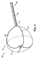
図6は、本発明の実施形態に係る組織領域にアブレーション治療を適用するための別例の装置600を示す部分断面図である。装置600は、長尺状本体602を有するカテーテルを備える。装置600はまた、長尺状本体602の遠位部またはその近くに配置されたバルーン構造体604を備える。バルーン構造体604は、バルーン構造体に供給される液体または膨張流体に応答して膨張するように構成される。加えて、バルーン構造体604は、第1の部分606と第2の部分608とを備える。ある場合には、バルーン構造体604の第1の部分606は、(バルーン構造体604の膨張に応答して)その中を貫通して液体を透過するように構成され、バルーン構造体604の第2の部分608は、長尺状本体602を組織領域に固定するように構成される。
FIG. 6 is a partial cross-sectional view showing another
バルーン構造体604は、アブレーションの為に組織領域またはその内部に配置される。ある場合には、組織領域は、肺静脈または腎静脈などの血管である。バルーン構造体604は、部分610が血管壁に接するように血管の内部に配備するように構成される。第1の部分606は、組織領域に対して(例えば、血管壁)、液体を透過する。液体は、血管の内部の狭窄を低減する抗狭窄薬を含有する。加えて、第2の部分608は、長尺状本体602を血管の内部に固定する。
The
ある場合には、長尺状本体602は、第1の部分606(または、チャンバー)の内部に配置された第1の開口部624を備え、長尺状本体602は、第2の部分608(または、チャンバー)の内部に配置された第2の開口部626を備える。第1の部分606(または、チャンバー)は、第1の開口部624を介して第1の部分606(または、チャンバー)の中に液体が流入するのに応答して、第1の部分を貫通して液体を流出するように構成される。加えて、第2の部分608は、第2の開口部626を介して第2の部分608(または、チャンバー)の中に液体が流入するのに応答して拡張して組織領域に長尺状本体602を固定するように構成される。第1の部分606を貫通して流出した液体は、組織領域で狭窄を低減するように構成される。
In some cases, the
ある場合には、装置600はまた、長尺状本体602の管腔の内部に配置されて、組織領域にエネルギーを送達するように構成された電極612を含む。ある場合には、電極612は、第1の部分606の内部に配置されて、付与される直流に応答してエネルギーを送達するように構成される。電極612からのアブレーションエネルギーは、外部電源/制御装置によって生成されて長尺状本体602の内部のワイヤ614を介して伝達される電場によりバルーン構造体604の第1の部分606の外面を介して付与される。装置600は、グランドを形成するか、電極612と閉鎖ループを形成するように構成された先端電極616を備える。先端電極616は、長尺状本体602の内部に配置されたワイヤ618を介して外部電源/制御装置に接続される。ある場合には、上記のように、電場は、電極612に直流を流すことによって生成される。直流の使用により、アブレーションエネルギーを受け取る組織に対してアポトーシス細胞死を誘導することができる。直流は、組織領域の細胞に、不可逆性の(例えば、閉じない)孔を形成することができる。組織に接触したバルーン構造体604は、アブレーションエネルギーの下流への拡散を抑制しつつ標的部位に調節された直接的なアブレーションを実施することができる。加えて、装置600は、先端電極616に配置されたコントラストポート628を備える。コントラストポート628は、アブレーション600の前およびその最中に装置600の可視化を支援する為に、その中を通過して造影剤を排出するように構成される。コントラストポート628は、長尺状本体602の中心軸から偏倚される。ある場合には、先端電極616は、複数の側面分岐部の中に誘導し易くする為に複数の偏倚させたコントラストポート628を備える。
In some cases, the
電気エネルギーは、バルーン構造体604の第1の部分606を貫通して透過した液体を介して組織領域(例えば、血管)に伝達される。電場は、アブレーションエネルギーを受け取る組織にアポトーシス細胞死を少なくとも部分的に引き起こすことによって組織の壁の内部の神経線維に沿ってその活動を変更する。ある場合には、アブレーションの為に電場が適用されている間に、バルーン構造体604の第1の部分606から液体を組織に対して投与し続けることができる。電極612を介して実施されるアブレーション工程は、アブレーションエネルギーを受け取る組織に対して液体(または生理食塩水と抗有糸分裂薬との組み合わせ)として抗有糸分裂薬の投与と同時且つ一時に、または液体の投与に続いて実施することができる。
Electrical energy is transmitted to the tissue region (eg, blood vessels) via a liquid that has penetrated through the
装置600は、バルーン構造体604の内部に配置されたペーシング電極620,622を備える。ペーシング電極620,622は、心電図や、単相性活動電位(MAPs)や、等時性電気活動マップなどを生成する為に心筋組織内の電気事象が検知できるようにマッピング信号処理装置に対して電気的に接続される。ペーシング電極620,622によって、医師は、組織領域の電気的な活動を測定することができ(例えば、電気的な活動が無いことは、組織がアブレーションされていることを示し、電気的な活動があることは、組織が生きていることを示す)、アブレーション治療のための標的部位を決定することができる。
The
ある場合には、装置600は、ステアリング機構630を備える。ステアリング機構630は、バルーン構造体604、長尺状本体602またはバルーン構造体604と長尺状本体602の双方をガイドするように構成される。図6に示すように、ステアリング機構630は、長尺状本体602の内部の中心に配置される。ステアリング機構630は、バルーン構造体604及び長尺状本体602のうちの少なくともいずれか一方を、ステアリング機構に付与される力に基づいて複数の方向にガイドする。ステアリング機構630は、カテーテルハンドルに接続されたワイヤ(例えば、図1に示す)であり得る。
In some cases,
図7は、本発明の実施形態に係る組織領域に対してアブレーション治療を実施するための別例の装置700を示す部分断面図である。装置700は、長尺状本体702と長尺状本体702に取り付けられたバルーン構造体704とを備えるカテーテルを含む。バルーン構造体704は、液体または膨張媒体に応答して膨張するように構成される。加えて、バルーン構造体604は、第1の部分706と第2の部分708とを含む。ある場合には、バルーン構造体704の第1の部分706は、その内部を貫通して液体を透過するように構成され(バルーン構造体704の膨張に応答して)、バルーン構造体704の第2の部分708は、組織領域に長尺状本体702を固定するように構成される。
FIG. 7 is a partial cross-sectional view showing another
バルーン構造体704は、アブレーションの対象である組織領域またはその内部に配置される。ある例では、組織領域は、肺静脈または腎静脈などの血管である。第1の部分706は、組織領域(例えば、血管)に対して液体を透過する。液体は、血管の内部で狭窄を低減する抗狭窄薬を含み得る。加えて、第2の部分708は、血管の内部にて長尺状本体702を固定する。
The
電気エネルギーは、バルーン構造体704の第1の部分706を貫通して通過する液体を介して組織領域(例えば、血管)に伝達される。電場は、アブレーションエネルギーを受け取る組織にアポトーシス細胞死を少なくとも部分的に引き起こすことによって組織の壁の内部の神経線維に沿ってその活動を変更する。ある場合には、アブレーションの電場を付与している間に、バルーン構造体704の第1の部分706から組織に対して液体を投与し続けることができる。電極712を用いて実施されるアブレーション工程は、抗有糸分裂薬を液体(または、生理食塩水と抗有糸分裂薬との組み合わせ)としてアブレーションエネルギーを受け取る組織に対して投与するのと同時かつ一時に、または液体の投与に続けて実施することができる。第1の部分704の内部で長尺状本体702に配置された電極712は、組織領域にエネルギーを送達するように構成される。電極712からのアブレーションエネルギーは、外部電源/制御装置によって生成されて長尺状本体702の内部のワイヤ714を介して伝達される電場によりバルーン構造体704の第1の部分706の外面を介して適用される。ある場合には、上記のように、電場は、電極712に直流を流すことによって生成される。直流を用いることによって、アブレーションエネルギーを受け取る組織に対してアポトーシス細胞死を引き起こすことができる。直流は、組織領域の細胞に不可逆性の(例えば、閉じない)孔を形成する。組織に接触したバルーン構造体704は、アブレーションエネルギーの下流への拡散を抑制しつつ標的部位に対して制御された直接的なアブレーションを実施することができる。
Electrical energy is transmitted to tissue regions (eg, blood vessels) via a liquid that passes through the
先端電極716は、グランドを形成するか、電極712と閉鎖ループを形成する為に使用される。先端電極716も外部電源/制御装置に接続することができる。加えて、装置700は、先端電極716に配置されたコントラストポート710を備える。コントラストポート710は、アブレーションの前または最中において装置700を可視化する為に、ポートの中を貫通して造影剤を排出するように構成される。コントラストポート710は、先端電極716の遠位端に配置される。
バルーン構造体704の内部に配置されたペーシング電極720,722は、組織領域の電気的な活動を決定するように構成される。ペーシング電極720、722は、組織の損傷の程度を推定する為にアブレーションの前に使用される。加えて、ペーシング電極720,722は、アブレーションの程度を決定する為にアブレーションの後に使用される。ペーシング電極720,722は、心電図や、単相性活動電位(MAPs)や、等時性電気活動マップなどを生成する為に、心筋組織の電気事象を検知できるようにマッピング信号処理装置に対して電気的に接続される。ペーシング電極720,722によって、医師は、組織領域の電気的な活動を測定して(例えば、電気的な活動が無いことは、組織がアブレーションされていることを示し、電気的な活動があることは、組織が生きていることを示す)、アブレーション治療の対象となる標的部位を決定することができる。
The pacing electrodes 720,722 located within the
ある場合において、装置700は、操縦可能であり、第1のステアリングワイヤ724と第2のステアリングワイヤ726とを含む。第1のステアリングワイヤ724および第2のステアリングワイヤ726は、バルーン構造体704、または長尺状本体702、またはバルーン構造体704および長尺状本体702の双方をガイドするように構成される。第1のステアリングワイヤ724および第2のステアリングワイヤ726は、中央の管腔728の両側において長尺状本体702の内部に配置される。上記で詳細に説明したように、中央の管腔728は、第1の部分706および第2の部分708のそれぞれに液体を運搬する部分を備える。第1のステアリングワイヤ724および第2のステアリングワイヤ726は、付与される力に基づいて、バルーン構造体704および長尺状本体702のうちの少なくともいずれか一方を複数の方向にガイドすることができる。第1のステアリングワイヤ724と第2のステアリングワイヤ726とは、カテーテルハンドル(例えば、第1に示す)に対して連結することができる。
In some cases,
ある場合には、第1の部分706および第2の部分708の一方または双方は、ステント支持構造体730を備える。ステント支持構造体730は、第1の部分706および第2の部分708の一方または双方の構造上の安定性を高めることができる。
In some cases, one or both of the
図8は、本発明の実施形態に係る組織領域に対してアブレーション治療を実施する為の別例の装置を示す部分断面図である。装置800は、長尺状本体802と長尺状本体802に取り付けられたバルーン構造体804とを有するカテーテルを含む。バルーン構造体804は、第1の部分806と第2の部分808とを備える。ある場合には、バルーン構造体804の第1の部分806は、それを貫通して液体を透過するように構成され、バルーン構造体804の第2の部分808は、バルーン構造体804の膨張に応答して組織領域に長尺状本体802を固定するように構成される。バルーン構造体804は、アブレーションの対象である組織領域またはその内部に配置される。ある場合には、組織領域は、肺静脈または腎静脈などの血管である。第1の部分806は、組織領域(例えば、血管)に対して液体を透過できる。液体は、血管の内部において狭窄を低減する抗狭窄薬剤を含有する。加えて、第2の部分808は、血管の内部に長尺状本体802を固定する。
FIG. 8 is a partial cross-sectional view showing another device for performing ablation treatment on the tissue region according to the embodiment of the present invention. The
電気的なエネルギーは、バルーン構造体804の第1の部分806を貫通して通過する液体を介して組織領域(例えば、血管壁)に伝達できる。電場は、アブレーションエネルギーを受け取る組織にアポトーシス細胞死を少なくとも部分的に引き起こすことによって組織の壁の内部の神経線維に沿って活動を変更する。ある場合には、アブレーションの電場を付与しつつ、組織に対してバルーン構造体804の第1の部分806を介して液体を投与し続けることができる。電極812を用いて実施されるアブレーションの工程は、アブレーションのエネルギーを受け取る組織に対して液体(または、生理食塩水と抗有糸分裂薬の組み合わせ)として抗有糸分裂薬の投与と同時かつ一時に、または液体の投与に続いて実施することができる。電極812からのアブレーションエネルギーは、外部電源/制御装置によって生成され、長尺状本体802の内部のワイヤ814を介して伝達される電場によってバルーン構造体804の第1の部分806の外面を介して付与される。
Electrical energy can be transferred to the tissue region (eg, vessel wall) via a liquid that passes through the
装置800の先端部分810は、組織領域にバルーン構造体804の位置決めを容易にするように構成される。先端部分810は、患者の心臓の左心房にアクセスするために心房中隔の孔を介して長尺状本体802およびバルーン構造体804を通過するのを支援する中央孔816を備える。中心孔816は、その中を貫通してガイドワイヤを通過させて、中隔において先端部分810の位置決めを支援する。次に、中隔に孔をあける為に、穿孔器具が、長尺状本体802の中を通って中心孔816を貫通して配置される。中心孔816は、アブレーションの前とその最中に装置800の可視化を支援する為に内部を貫通して造影剤を排出するように構成することもできる。
The
可視化を支援する為に、可視化要素824も使用することができる。可視化要素824は、カメラと光源(例えば、光放出ダイオード(LED))とを備える。可視化要素824は、長尺状本体802に配置されて、撮像して装置800を操作する医師にビデオ画像を提供するように構成される。バルーン構造体804を肺静脈(図2に示すように)の内部等の組織領域に配置した後に、バルーン構造体804は、拡張される。バルーン構造体804の膨張は、バルーン構造体804の外面を血管の内壁に接触させる。より詳細には、バルーン構造体804の第2の部分808は、血管内部に長尺状本体802を固定する。可視化要素824は、組織領域を介して血液の流れを観察するのに使用される。ある場合には、第2の部分808は、第1の部分806から流出した液体が組織領域に対して直接的に投与されるように組織領域から血液の流れを阻止する。血液の流れをブロックすることによって、組織領域から運搬される液体(例えば、抗狭窄薬剤)を抑制できる。抗狭窄薬剤を含む液体は、組織領域に接触して(血管の内壁)、電極812を介して付与されたアブレーションエネルギーを付与した結果生じ得る狭窄の形成を低減できる。
A
バルーン構造体804の内部に配置されたペーシング電極820,822は、組織領域の電気的な活動を決定するように構成される。ペーシング電極820,822は、組織のダメージの程度を見積もるためにアブレーションの前に用いられる。加えて、ペーシング電極820,822は、アブレーションの程度を決定する為にアブレーション後に用いられる。ペーシング電極820,822は、心電図や、単相性活動電位(MAPs)や、等時性電気活動マップなどを生成する為に心筋組織の電気事象を検知できるようにマッピング信号処理装置に対して電気的に接続される。ペーシング電極820,822により、医師は、組織領域の電気的な活動を測定して(例えば、電気的な活動が無いことは、組織がアブレーションされたことを示し、電気的な活動があることは、組織が生きていることを示す)、アブレーション治療の為に標的部位を決めることができる。
Pacing electrodes 820,822 located within the
図6〜8に示す例示の構成要素は、開示されている発明の主題にかかる実施形態の使用または機能の範囲に関して如何なる限定を示唆するものではない。例示の構成要素は、図示されている任意の単一の構成要素または構成要素の組み合わせについて従属性や必要性を有すると理解してはならない。加えて、図6〜8のいずれかに示す構成要素の任意の1つ以上は、実施形態において、この図に示されている別の複数の構成要素と組み合わせることができ、その全ては、開示された発明の主題の範囲内に入ると考えられる。例えば、ペーシング電極520,522は、装置300および装置400と組み合わせて使用できる。加えて、装置300および装置400は、図6〜8について説明したステアリング機構および可視化要素のうちの少なくともいずれか一方を備えることができる。さらに、装置600〜800の先端部分は、図5について上記したように収縮可能である。
The exemplary components shown in FIGS. 6-8 do not imply any limitation with respect to the use or scope of function of such embodiments in the subject matter of the disclosed invention. The illustrated components should not be understood to have dependencies or needs for any single component or combination of components shown. In addition, any one or more of the components shown in any of FIGS. 6-8 may, in embodiments, be combined with a plurality of other components shown in this figure, all of which are disclosed. It is considered to fall within the scope of the subject matter of the invention. For example, the pacing
図9Aは、本発明の実施形態に係る第1のマルチチャンバー構成を有する装置であって、組織領域に対して狭窄防止を実施する為の別例の装置を示す部分断面図である。装置900は、長尺状本体902およびバルーン構造体904を含む。図9Aに示す第1のマルチチャンバー構成では、バルーン構造体904は、組織領域に長尺状本体902を固定するように構成された2つのチャンバー906,908を含む。チャンバー906,908は、バルーン構造体904を膨張させる為に使用される液体に対して不透過性である。バルーン構造体904は、それを貫通して液体を透過するように構成された第3のチャンバー910を備えることができる。液体は、抗狭窄薬剤であり、組織領域で狭窄の形成を防止することができる。
FIG. 9A is a partial cross-sectional view showing an apparatus having the first multi-chamber configuration according to the embodiment of the present invention, which is another example for implementing stenosis prevention in a tissue region. The
図9Bは、本発明の実施形態に係る第2のマルチチャンバー構成を有する、狭窄防止を行う為の装置900を図9Aに示したように示す図である。図9Bに示す第2のマルチチャンバー構成では、バルーン構造体904は、組織領域に長尺状本体902を固定するように構成された2つのチャンバー906,908を備える。チャンバー906,908は、バルーン構造体904を膨張するために用いられる液体に対して不透過性である。第3のチャンバー910は、その内部を貫通して液体を透過するように構成される。液体は、抗狭窄薬剤であり、組織領域で狭窄が形成されるのを防止することができる。チャンバー906,908は、より大きな第3のチャンバー910を可能にする為に、第1の形態のチャンバー906,908よりも小さい。
FIG. 9B is a diagram showing a
図9Cは、本発明の実施形態に係る第3のマルチチャンバー構成を有する、狭窄防止を行う為の装置900を図9A、9Bに示したように示す図である。図9Bに示す第3のチャンバー構成では、バルーン構造体904は、組織領域に長尺状本体902を固定するように構成された3つのチャンバー906,908,912を含む。チャンバー906,908,912は、バルーン構造体904を膨張するのに用いられる液体に対して不透過性である。装置は、その内部を貫通して液体を透過するように構成された第3のチャンバー910と、同じくその内部を貫通して液体を透過するように構成された第4のチャンバー914とを備える。液体は、抗狭窄薬剤であり、組織領域で狭窄の形成を防止することができる。第3の形態では、装置900は、液体(例えば、抗狭窄薬剤)が透過する透過可能部916,918の2つの領域を含む。装置900の第1、第2、第3の形態のいずれも、上で詳しく説明したように、アブレーションエネルギーを付与するように構成された電極を備えることができる。電極は、液体を透過するチャンバーの内部に配置される。
FIG. 9C is a diagram showing a
図10は、本は発明の実施形態に係るマルチチャンバー形態を有する、組織領域に対して狭窄防止を行う為の別例の装置1000を示す図である。装置1000は、カテーテルの長尺状本体1008に沿って3つのチャンバー1002,1004,1006を備える。3つのチャンバー1002,1004,1006のそれぞれは、内部を貫通して抗狭窄性の液体を透過するように構成される。ある場合には、3つのチャンバー1002,1004,1006の全ては、液体に対して透過性であり、別の場合には、3つのチャンバー1002,1004,1006のうちの一部のみが液体に対して透過性である。透過性(又はそれを欠く)は、3つのチャンバー1002,1004,1006の間で異なり得る。3つのチャンバー1002,1004,1006のいずれも上記に詳しく説明したようにアブレーションエネルギーを付与するように構成された電極も備えることができる。
FIG. 10 is a diagram showing another
図11Aは、本発明の実施形態に係る組織領域に対してアブレーション治療を実施する為の別例の装置1100を示す図である。装置1100は、長尺状本体1102と長尺状本体1102に対して取り付けられたバルーン構造体1104とを有するカテーテルを含む。バルーン構造体1104は、膨張する前に長尺状本体1102から入れ子になるように構成される。図11Aに示すように、バルーン構造体1104は、長尺状本体1102から入れ子する前には、第1の形態で配置される。
FIG. 11A is a diagram showing another
第2のバルーン構造体1106は、長尺状本体1102に配置される。第2のバルーン構造体1106は、可視化要素1108を収容する。可視化要素1108も、アブレーション治療を実施する間に可視化を支援する為に使用することができる。可視化要素1108は、カメラと光源(例えば、LED)とを備える。可視化要素1108は、撮像して装置1100を操作する医師にビデオ画像を提供するように構成される。
The
第1の形態で、長尺状本体1102とカテーテルとは、組織領域に案内される。より詳細には、長尺状本体1102とカテーテルとは、患者の心臓の内部に案内される。患者の心臓に案内された後(例えば、図2について説明したように)、バルーン構造体1104は、組織領域に配置される。ある場合には、組織領域は、肺静脈などの血管である。そのような場合には、バルーン構造体1104は、その血管の内部に配置される。
In the first embodiment, the
図11Bは、アブレーション治療を実施する為の装置1100を、本発明の実施形態に係る第2の形態で、図11Aに示したように、示す図である。第2の形態では、バルーン構造体1104は、長尺状本体1102から入れ子にされていてまだ膨張されていない。組織領域(血管内部に)へのバルーン構成1104の配置は、バルーン構造体1104を第1の形態と第2の形態との間で移行する間か、またはバルーン構造体1104を第2の形態に移行した後に行われる。バルーン構造体1104は、カテーテルハンドルに連結した長尺状本体1102の内部に配置された部分を含む。この部分は、バルーン構造体1104を入れ子にする為に、長尺状本体1102の内部で摺動するように構成される。
FIG. 11B is a diagram showing an
図11Cは、アブレーション治療を実施する為の装置1100を、本発明の実施形態に係る第3の形態で、図11A〜11Bに示したように示す図である。第3の形態では、バルーン構造体1104は、膨張されている。バルーン構造体1104は、第1の部分1110と第2の部分1102とを備える。ある場合には、バルーン構造体1104の第1の部分1110は、その内部を貫通して液体が透過するように構成され、バルーン構成1104の第2の部分1112は、バルーン構造体1104の膨張に応答して組織領域にバルーン本体1102を固定するように構成される。したがって、バルーン構造体1104の第1の部分1110は、第1の透過性を備え、バルーン構造体1104の第2の部分1112は、第2の透過性を備え、第1の透過性は、第2の透過性よりも大きい。バルーン構造体1104は、アブレーションの対象である組織領域またはその内部に配置される。ある場合には、組織領域は、肺静脈または腎静脈等の血管である。第1の部分1110は、組織(例えば、血管壁)に対して液体を透過する。液体は、血管の内部で狭窄を低減する抗狭窄薬剤を含有してよい。加えて、第2の部分1112は、血管内部に長尺状本体1102を固定することができる。
FIG. 11C is a diagram showing the
電極1114を介して実施されるアブレーション工程は、アブレーションエネルギーを受け取る組織に対して抗有糸分裂薬の投与と同時且つ一時に、または液体の投与に続いて実施することができる。電気エネルギーは、バルーン構造体1104の第1の部分1110の中を透過する液体を介して組織領域に伝達できる。電場は、アブレーションエネルギーを受け取る組織に対してアポトーシス細胞死を少なくとも部分的に引き起こすことによって組織の壁の内部の神経線維に沿って活動を変更することができる。ある場合には、アブレーション用の電場を付与しつつ、バルーン構造体1104の第1の部分1110を介して組織に対して液体を透過し続けることができる。電極1114からのアブレーションエネルギーは、外部電源/制御装置によって生成され、電極1114に接続したワイヤを介して伝達される電場によって、バルーン構造体1104の第1の部分1110の外面を介して付与される。
The ablation step performed via the electrode 1114 can be performed simultaneously and simultaneously with the administration of the antimitotic agent to the tissue receiving the ablation energy, or following the administration of the liquid. Electrical energy can be transmitted to the tissue region via a liquid that permeates through the
肺静脈(図2に示すように)内部等の組織領域にバルーン構造体1104を配置した後、バルーン構造体1104を膨張することによって、バルーン構造体1104の外面を血管の内壁に接触させることができる。より詳細には、バルーン構造体1104の第2の部分1112は、長尺状本体1102を血管内部に固定することができる。可視化要素1108は、組織領域を介して血流を観察するのに使用することができる。ある場合には、第2の部分1112は、第1の部分1110から流出した液体が組織領域に対して直接的に適用されるように組織部分から血液をブロックする。血流をブロックすることにより、液体(例えば、抗狭窄薬剤)が組織領域から運搬されることを低減できる。抗狭窄薬を含む液体は、組織領域に接触して、電極1114を介して適用されるアブレーションエネルギーを付与する結果として生じ得る狭窄の形成を低減できる。
After placing the
加えて、バルーン構造体1104は、その内部に配置されたペーシング電極1116,1118を備える。ペーシング電極1116,1118は、組織領域の電気的な活動を決定するように構成される。ペーシング電極1116,1118は、組織のダメージの程度を見積もるためにアブレーションの前に使用することができる。加えて、ペーシング電極1116,1118は、アブレーションの程度を決定する為にアブレーションの後に使用することができる。ペーシング電極1116,1118は、心電図や、単相性活動電位(MAPs)や、等時性電気活動マップを作成する為に心筋組織の電気事象を検知できるように、マッピング信号処理装置に対して電気的に接続される。ペーシング電極1116,1118によって、医師は、組織領域の電気的な活動を測定することができる(例えば、電気的な活動が無いことは、組織がアブレーションされていることを示し、電気的な活動があることは、組織が生きていることを示す)。
In addition, the
ある場合には、バルーン構造体1104が配備されると(例えば、肺静脈内)、バルーン構造体1104は、肺静脈が分れる2分岐方向に向かってできるだけ遠位に配置される。この時点で、第2の部分1112は、膨張されて、長尺状本体1102を前記血管の内部に固定する。第2部分1112の膨張により左心室への血流は停止され、これは、可視化要素1108で確認できる。次に、ペーシング電極1116,1118は、肺静脈の電気的な活動を測定する。ペーシング電極1116,1118による測定によりアブレーション治療のための基準線を形成することができる。アブレーション治療は、ペーシング電極1116,1118での測定に基づいて、第1の部分1110を貫通して透過された液体を介して、抗狭窄薬剤の放出と共に、電極1114を介して実施される。ある場合には、液体は、アブレーション治療の前に第1の部分1110を貫通して透過する。可視化要素1108及び超音波のうちの少なくともいずれか一方により、電極1114を用いてアブレーションを適用する前に、液体(例えば、生理食塩水と抗狭窄薬)が血管壁に流れていることを確認することができる。
In some cases, when the
アブレーションを実施した後、ペーシング電極1116,1118を再度用いて電気的な活動が測定される。読み取り値に基づいて、アブレーションの程度が所望のレベルに達していた場合には、バルーン構造体1104は、収縮されて肺静脈から除去される。ある場合には、バルーン構造体1104は、肺静脈に沿って第2のアブレーション部位に移動される。第2の部分1112は、バルーン構造体1104を再配置する間、膨張されたままであってよい。第2のアブレーションの電気的な活動は、ペーシング電極1116,1118で測定されて、液体の透過とアブレーションが実施される。この工程は、所望するアブレーションのレベルが達成されるまで繰り返すことができる。第2のアブレーション部位への移動(例えば、5mm)は、ペーシング電極1116,1118によって測定した電気的な活動の変化に基づいて決定することができる。加えて、電極1114は、様々なパルス幅パターンと振幅とで(例えば、1000〜3000ボルトで1〜30マイクロ秒パルス)、それに対して流した直流を介して電気エネルギーを適用ことができる。アブレーション術に関するさらなる詳細については、ペーシング電極1116,1118のマッピング使用を含めて、図1及び関連の記載を参照されたい。
After ablation, electrical activity is measured using the
図11A〜11Cに示す例示の構成要素は、開示された発明の主題に係る実施形態の使用または機能の範囲に関して如何なる限定を示唆するものではない。例示の構成要素は、図に示す任意の単一の構成要素または複数の構成要素の組み合わせに関して従属性または必要性を有すると解してはならない。加えて、図11A〜11Cのいずれかに示した構成要素の任意の1つ以上は、実施形態において、そこに示されている様々な別の構成要素(および示されていない構成要素のうちの少なくともいずれか一方)と組み合わせることができ、その全ては、開示されている発明の主題の範囲内に含まれると考えられる。 The exemplary components shown in FIGS. 11A-11C do not imply any limitation with respect to the use or scope of function of embodiments of the subject of the disclosed invention. The illustrated components should not be construed as having a dependency or need with respect to any single component or combination of components shown in the figure. In addition, any one or more of the components shown in any of FIGS. 11A-11C will, in embodiments, of the various other components (and not shown) shown therein. It can be combined with at least one), all of which are considered to be within the scope of the disclosed subject matter of the invention.
図12は、本発明の実施形態に係る組織領域に対して狭窄防止を行う為の例示のバルーン構造体1200を示す図である。バルーン構造体1200は、透過部1202と不透過部1204とを備える。透過部1202は、複数のナノ構造1206を備える。ある場合には、ナノ構造1206は、液体、例えば抗狭窄薬剤を包含する為のコア材料として機能する中空状の繊維である。別の場合には、複数のナノ構造1206は、液体、例えば抗狭窄薬剤を、複数のナノ構造1206の間の間隙に包含することができる。いずれの場合でも、複数のナノ構造1206は、透過部1202の内部に斜交平行ネットワークを形成することができる。
FIG. 12 is a diagram showing an
複数のナノ構造1206は、線維の配置、繊維の焼結(熱的または化学的)、親水性または疎水性コーティング、またはその他の同様の工程によってバルーン構造体1200の上に配置することができる。加えて、透過部1202は、一の層が複数のナノ構造1206を備え、別の層が、複数のナノ構造1206からの液体の放出を抑制する為にその上に配置されるなどして複数の層を備えることができる。液体は、バルーン構造体1200の膨張に応答してその上に配置された層の有無に拘わらず、複数のナノ構造1206から排出される。抗狭窄薬剤などの液体は、組織の中への拡散によって組織領域に送達されるか、バルーン構造体1200の内部に配置された電極(図示略)に由来する電気的な力によってイオノフォレシス(ionophoresis)によって駆動できる。別の場合には、複数のナノ構造1206は、バルーン構造体1200の上の抗狭窄薬剤のコーティングで置き換えることもできる。これは、抗狭窄薬を水または生理食塩水と組み合わせることを含む(例えば、40/40/20のエタノール/アセトン/水で、4.86%の80/20のptx/ATBC)。ある場合には、バルーン構造体1200は、複数の層を有する。1つ以上の抗狭窄薬、生理食塩水、または別の薬剤をバルーン構造1200の異なる層の内部に含侵することができる。抗狭窄薬、生理食塩水、または別の薬剤は、バルーン構造体1200の複数の異なる層を用いて順番に送達することができる。加えて、バルーン構造体1200は、抗狭窄薬、生理食塩水、または別の薬剤を順次送達する為にその異なる部分に異なる層を備えることができる。
The plurality of
図12に示す例示の構成要素は、開示されている発明の主題の実施形態の使用または機能に関して如何なる制限をも示唆していない。例示の構成要素は、図に示す任意の単一の構成要素または複数の構成要素の組み合わせに関する如何なる従属性や必要性を有すると解してはならない。加えて、図12に示されている構成要素の任意の1つ以上は、実施形態において、そこに示されている別の構成要素(及び示されていない構成要素のうちの少なくともいずれか1つ)と組み合わせることができ、その全ては、開示されている発明の主題の範囲内に入ると考えられる。例えば、ナノ構造1206は、この明細書で説明した任意のバルーン構造体と組み合わせて使用することができる。
The illustrated components shown in FIG. 12 do not suggest any limitation with respect to the use or function of embodiments of the subject matter of the disclosed invention. The illustrated components should not be construed as having any dependency or need for any single component or combination of components shown in the figure. In addition, any one or more of the components shown in FIG. 12 is, in the embodiment, at least one of the other components (and not shown) shown therein. ), All of which are considered to fall within the subject matter of the disclosed invention. For example,
本発明の範囲を逸脱することなく記載の例示の実施系他に対して様々な変更や追加を行うことができる。例えば、上記の実施形態が特定の要素に関するものであっても、本発明の範囲は、要素の異なる組み合わせを含む実施形態および説明した要素の必ずしも全てを含まない実施形態も含む。したがって、本発明の範囲は、全ての均等物と共に、請求項の範囲内に入るそのような全ての代替形態と変更形態と変化形態を包含するものとする。 Various changes and additions can be made to the above-exemplified implementation systems and the like without departing from the scope of the present invention. For example, even though the above embodiments relate to specific elements, the scope of the invention also includes embodiments that include different combinations of elements and embodiments that do not necessarily include all of the described elements. Accordingly, the scope of the present invention shall include all such alternatives, modifications and variations within the scope of the claims, as well as all equivalents.
Claims (15)
血管にアクセスする為の寸法と形状とを備え、近位端と遠位端の間に延びる長尺状本体を有するカテーテルと、
前記長尺状本体の前記遠位端の近くに配置されて、第1の透過性を有する第1の部分と、第2の透過性を有する第2の部分とを含むバルーン構造体と、前記第1の透過性は、前記第2の透過性とは異なることと、
前記バルーン構造体および前記バルーン構造体の内部のいずれか一方に配置されてアブレーション治療の標的部位を決定するように構成された1つ以上のマッピング電極と、
前記バルーン構造体および前記バルーン構造体の内部のうちのいずれか一方に配置されて前記組織領域にエネルギーを伝達する1つ以上の電極と、
前記カテーテルの遠位端に配置されてグランドを形成することおよび前記1つ以上の電極と閉鎖ループを形成することのうちのいずれか一方である先端電極と
からなる装置。 In a device for applying ablation therapy to a tissue area
A catheter with an elongated body that has dimensions and shapes to access blood vessels and extends between the proximal and distal ends.
A balloon structure located near the distal end of the elongated body and comprising a first portion having a first permeability and a second portion having a second permeability. the first permeability, and Rukoto different from the said second permeability,
With one or more mapping electrodes located either inside the balloon structure or inside the balloon structure and configured to determine the target site for ablation therapy.
One or more electrodes for transmitting energy to the tissue region is disposed on either the inside of the inner Neu displacement of the balloon structure and the balloon structure,
A device consisting of a tip electrode located at the distal end of the catheter to form a gland and one of the one or more electrodes and a closed loop .
Applications Claiming Priority (3)
| Application Number | Priority Date | Filing Date | Title |
|---|---|---|---|
| US201662413249P | 2016-10-26 | 2016-10-26 | |
| US62/413,249 | 2016-10-26 | ||
| PCT/US2017/058376 WO2018081323A1 (en) | 2016-10-26 | 2017-10-25 | Stenosis prevention and ablation delivery system |
Publications (3)
| Publication Number | Publication Date |
|---|---|
| JP2019532759A JP2019532759A (en) | 2019-11-14 |
| JP2019532759A5 JP2019532759A5 (en) | 2020-10-22 |
| JP6811319B2 true JP6811319B2 (en) | 2021-01-13 |
Family
ID=60409343
Family Applications (1)
| Application Number | Title | Priority Date | Filing Date |
|---|---|---|---|
| JP2019522581A Active JP6811319B2 (en) | 2016-10-26 | 2017-10-25 | Stenosis prevention and ablation transfer system |
Country Status (5)
| Country | Link |
|---|---|
| US (1) | US10716621B2 (en) |
| EP (1) | EP3531948A1 (en) |
| JP (1) | JP6811319B2 (en) |
| CN (1) | CN110191688A (en) |
| WO (1) | WO2018081323A1 (en) |
Families Citing this family (6)
| Publication number | Priority date | Publication date | Assignee | Title |
|---|---|---|---|---|
| WO2018081323A1 (en) | 2016-10-26 | 2018-05-03 | Boston Scientific Scimed Inc. | Stenosis prevention and ablation delivery system |
| EP3634284A1 (en) * | 2017-06-06 | 2020-04-15 | Cardiac Pacemakers, Inc. | Ablation delivery using a catheter having a semi-permeable inflatable balloon structure |
| US10874388B2 (en) | 2017-11-30 | 2020-12-29 | Boston Scientific Scimed, Inc. | Connected anchor delivery systems and methods for valve repair |
| US20200205889A1 (en) * | 2018-12-28 | 2020-07-02 | Biosense Webster (Israel) Ltd. | Balloon Catheter with Distal End Having a Recessed Shape |
| BR112023020624A2 (en) | 2021-04-07 | 2023-12-05 | Btl Medical Dev A S | PULSED FIELD ABLATION DEVICE AND METHOD |
| IL309432A (en) | 2021-07-06 | 2024-02-01 | Btl Medical Dev A S | Pulsed field ablation device and method |
Family Cites Families (21)
| Publication number | Priority date | Publication date | Assignee | Title |
|---|---|---|---|---|
| US5256141A (en) | 1992-12-22 | 1993-10-26 | Nelson Gencheff | Biological material deployment method and apparatus |
| US8025661B2 (en) * | 1994-09-09 | 2011-09-27 | Cardiofocus, Inc. | Coaxial catheter instruments for ablation with radiant energy |
| US5961513A (en) * | 1996-01-19 | 1999-10-05 | Ep Technologies, Inc. | Tissue heating and ablation systems and methods using porous electrode structures |
| US6251109B1 (en) * | 1997-06-27 | 2001-06-26 | Daig Corporation | Process and device for the treatment of atrial arrhythmia |
| US6500174B1 (en) * | 1997-07-08 | 2002-12-31 | Atrionix, Inc. | Circumferential ablation device assembly and methods of use and manufacture providing an ablative circumferential band along an expandable member |
| US7674259B2 (en) * | 2000-12-09 | 2010-03-09 | Tsunami Medtech | Medical instruments and techniques for thermally-mediated therapies |
| US6529756B1 (en) * | 1999-11-22 | 2003-03-04 | Scimed Life Systems, Inc. | Apparatus for mapping and coagulating soft tissue in or around body orifices |
| US6620159B2 (en) * | 2001-06-06 | 2003-09-16 | Scimed Life Systems, Inc. | Conductive expandable electrode body and method of manufacturing the same |
| US20050010207A1 (en) * | 2002-09-10 | 2005-01-13 | Scimed Life Systems, Inc. | Microporous electrode structure and method of making the same |
| US7736362B2 (en) * | 2003-09-15 | 2010-06-15 | Boston Scientific Scimed, Inc. | Catheter balloons |
| US20090248012A1 (en) | 2008-03-27 | 2009-10-01 | The Regents Of The University Of California | Irreversible electroporation device and method for attenuating neointimal |
| US20100256629A1 (en) * | 2009-04-06 | 2010-10-07 | Voyage Medical, Inc. | Methods and devices for treatment of the ostium |
| CN103271766B (en) * | 2012-08-24 | 2015-08-26 | 苏州信迈医疗器械有限公司 | A kind of for mapping and melt the device being positioned at the kidney nerve that renal artery distributes |
| CA2882002C (en) * | 2012-08-24 | 2018-04-17 | Symap Medical (Suzhou) , Ltd. | Device for mapping and ablating renal nerves distributed on the renal artery |
| WO2014168987A1 (en) * | 2013-04-08 | 2014-10-16 | Shifamed Holdings, Llc | Cardiac ablation catheters and methods of use thereof |
| AU2014268737A1 (en) | 2013-05-20 | 2015-12-03 | Mayo Foundation For Medical Education And Research | Devices and methods for ablation of tissue |
| JP6159888B2 (en) * | 2013-08-22 | 2017-07-05 | ボストン サイエンティフィック サイムド,インコーポレイテッドBoston Scientific Scimed,Inc. | Flexible circuit with improved adhesion to renal neuromodulation balloon |
| EP3120792A1 (en) * | 2015-07-22 | 2017-01-25 | Fiorenzo Gaita | Catheter for cryogenic ablation |
| CN105147389B (en) * | 2015-10-22 | 2018-03-16 | 上海魅丽纬叶医疗科技有限公司 | Include the radio frequency ablation device and its ablation method of balloon occlusion type guiding catheter |
| CN105935314B (en) * | 2016-06-17 | 2018-09-18 | 赵学 | A kind of radio frequency ablation catheter with multiple spot mapping function |
| WO2018081323A1 (en) | 2016-10-26 | 2018-05-03 | Boston Scientific Scimed Inc. | Stenosis prevention and ablation delivery system |
-
2017
- 2017-10-25 WO PCT/US2017/058376 patent/WO2018081323A1/en unknown
- 2017-10-25 US US15/793,954 patent/US10716621B2/en active Active
- 2017-10-25 CN CN201780066568.5A patent/CN110191688A/en active Pending
- 2017-10-25 EP EP17801140.9A patent/EP3531948A1/en active Pending
- 2017-10-25 JP JP2019522581A patent/JP6811319B2/en active Active
Also Published As
| Publication number | Publication date |
|---|---|
| US20180110563A1 (en) | 2018-04-26 |
| US10716621B2 (en) | 2020-07-21 |
| CN110191688A (en) | 2019-08-30 |
| JP2019532759A (en) | 2019-11-14 |
| EP3531948A1 (en) | 2019-09-04 |
| WO2018081323A1 (en) | 2018-05-03 |
Similar Documents
| Publication | Publication Date | Title |
|---|---|---|
| JP6811319B2 (en) | Stenosis prevention and ablation transfer system | |
| US11426233B2 (en) | Ablation delivery using a catheter having a semipermeable inflatable balloon structure | |
| ES2960299T3 (en) | Devices for endovascular ablation of a splanchnic nerve | |
| US10524859B2 (en) | Therapeutic tissue modulation devices and methods | |
| ES2743974T3 (en) | Apparatus for renal neuromodulation | |
| ES2269214T3 (en) | APPLIANCE FOR THE EXPLORATION AND COAGULATION OF SOFT FABRICS IN BODY HOLES OR AROUND THEMSELVES. | |
| ES2247621T3 (en) | EXCAVATION PROBE. | |
| ES2757726T3 (en) | Catheter devices and systems for renal neuromodulation | |
| US9131982B2 (en) | Mediguide-enabled renal denervation system for ensuring wall contact and mapping lesion locations | |
| AU749417B2 (en) | Systems and methods for delivering drugs to selected locations within the body | |
| US20150223877A1 (en) | Methods and systems for treating nerve structures | |
| CN101600471B (en) | Methods and apparatus for renal neuromodulation | |
| JP2014517731A (en) | Iontophoretic catheter system and method for renal sympathetic denervation and iontophoretic drug delivery | |
| CN105636644A (en) | Devices, systems, and methods for the selective positioning of an intravascular ultrasound neuromodulation device | |
| JP2019532759A5 (en) | ||
| ES2855051T3 (en) | A device for localization and ablation of renal nerves distributed in the renal artery | |
| JP2023543848A (en) | Balloon catheter with microporous section | |
| CA3162954A1 (en) | Methods and devices for endovascular ablation of a splanchnic nerve |
Legal Events
| Date | Code | Title | Description |
|---|---|---|---|
| A621 | Written request for application examination |
Free format text: JAPANESE INTERMEDIATE CODE: A621 Effective date: 20190530 |
|
| A977 | Report on retrieval |
Free format text: JAPANESE INTERMEDIATE CODE: A971007 Effective date: 20200522 |
|
| A131 | Notification of reasons for refusal |
Free format text: JAPANESE INTERMEDIATE CODE: A131 Effective date: 20200609 |
|
| A524 | Written submission of copy of amendment under article 19 pct |
Free format text: JAPANESE INTERMEDIATE CODE: A524 Effective date: 20200909 |
|
| TRDD | Decision of grant or rejection written | ||
| A01 | Written decision to grant a patent or to grant a registration (utility model) |
Free format text: JAPANESE INTERMEDIATE CODE: A01 Effective date: 20201117 |
|
| A61 | First payment of annual fees (during grant procedure) |
Free format text: JAPANESE INTERMEDIATE CODE: A61 Effective date: 20201214 |
|
| R150 | Certificate of patent or registration of utility model |
Ref document number: 6811319 Country of ref document: JP Free format text: JAPANESE INTERMEDIATE CODE: R150 |
|
| R250 | Receipt of annual fees |
Free format text: JAPANESE INTERMEDIATE CODE: R250 |