JP6810454B2 - Light receiving optical system - Google Patents
Light receiving optical system Download PDFInfo
- Publication number
- JP6810454B2 JP6810454B2 JP2017054393A JP2017054393A JP6810454B2 JP 6810454 B2 JP6810454 B2 JP 6810454B2 JP 2017054393 A JP2017054393 A JP 2017054393A JP 2017054393 A JP2017054393 A JP 2017054393A JP 6810454 B2 JP6810454 B2 JP 6810454B2
- Authority
- JP
- Japan
- Prior art keywords
- light receiving
- optical system
- axis
- light
- fresnel lens
- Prior art date
- Legal status (The legal status is an assumption and is not a legal conclusion. Google has not performed a legal analysis and makes no representation as to the accuracy of the status listed.)
- Active
Links
- 230000003287 optical effect Effects 0.000 title claims description 213
- 238000003384 imaging method Methods 0.000 claims description 60
- 210000001747 pupil Anatomy 0.000 claims description 8
- 238000010586 diagram Methods 0.000 description 19
- 230000001678 irradiating effect Effects 0.000 description 4
- 230000000694 effects Effects 0.000 description 2
- 210000003128 head Anatomy 0.000 description 2
- 230000001154 acute effect Effects 0.000 description 1
- 238000005286 illumination Methods 0.000 description 1
- 238000000034 method Methods 0.000 description 1
- 238000000926 separation method Methods 0.000 description 1
- 230000001360 synchronised effect Effects 0.000 description 1
- 238000002834 transmittance Methods 0.000 description 1
Images


Classifications
-
- G—PHYSICS
- G01—MEASURING; TESTING
- G01J—MEASUREMENT OF INTENSITY, VELOCITY, SPECTRAL CONTENT, POLARISATION, PHASE OR PULSE CHARACTERISTICS OF INFRARED, VISIBLE OR ULTRAVIOLET LIGHT; COLORIMETRY; RADIATION PYROMETRY
- G01J1/00—Photometry, e.g. photographic exposure meter
- G01J1/02—Details
- G01J1/04—Optical or mechanical part supplementary adjustable parts
- G01J1/0407—Optical elements not provided otherwise, e.g. manifolds, windows, holograms, gratings
- G01J1/0411—Optical elements not provided otherwise, e.g. manifolds, windows, holograms, gratings using focussing or collimating elements, i.e. lenses or mirrors; Aberration correction
-
- G—PHYSICS
- G02—OPTICS
- G02B—OPTICAL ELEMENTS, SYSTEMS OR APPARATUS
- G02B3/00—Simple or compound lenses
- G02B3/02—Simple or compound lenses with non-spherical faces
- G02B3/08—Simple or compound lenses with non-spherical faces with discontinuous faces, e.g. Fresnel lens
-
- G—PHYSICS
- G02—OPTICS
- G02B—OPTICAL ELEMENTS, SYSTEMS OR APPARATUS
- G02B26/00—Optical devices or arrangements for the control of light using movable or deformable optical elements
- G02B26/08—Optical devices or arrangements for the control of light using movable or deformable optical elements for controlling the direction of light
- G02B26/0816—Optical devices or arrangements for the control of light using movable or deformable optical elements for controlling the direction of light by means of one or more reflecting elements
-
- G—PHYSICS
- G02—OPTICS
- G02B—OPTICAL ELEMENTS, SYSTEMS OR APPARATUS
- G02B26/00—Optical devices or arrangements for the control of light using movable or deformable optical elements
- G02B26/08—Optical devices or arrangements for the control of light using movable or deformable optical elements for controlling the direction of light
- G02B26/10—Scanning systems
- G02B26/105—Scanning systems with one or more pivoting mirrors or galvano-mirrors
-
- G—PHYSICS
- G02—OPTICS
- G02B—OPTICAL ELEMENTS, SYSTEMS OR APPARATUS
- G02B5/00—Optical elements other than lenses
- G02B5/18—Diffraction gratings
- G02B5/1876—Diffractive Fresnel lenses; Zone plates; Kinoforms
- G02B5/189—Structurally combined with optical elements not having diffractive power
Description
本発明は、周囲の物体の情報を収集するために光を受信する受光光学系に関する。 The present invention relates to a light receiving optical system that receives light to collect information on surrounding objects.
レーザなどの光を周囲の物体に照射して反射波を受信することにより周囲の物体の情報を収集するシステムであって、照射及び受信のために光学系を回転させるシステムが知られている(特許文献1)。このような装置においては、受信した光を電気信号に変換する受光素子を回転部分に設置する必要がある。受光素子を回転部分に設置すると、回転部分が大型になり、システム全体も大型化する。また、受光素子の出力である電気信号を回転部分から外部に取り出すための装置が必要となるなどシステムの構成が煩雑になる。 A system that collects information on surrounding objects by irradiating surrounding objects with light such as a laser and receiving reflected waves, and a system that rotates an optical system for irradiation and reception is known ( Patent Document 1). In such a device, it is necessary to install a light receiving element that converts the received light into an electric signal in the rotating portion. When the light receiving element is installed in the rotating portion, the rotating portion becomes large and the entire system also becomes large. In addition, the system configuration becomes complicated, for example, a device for extracting an electric signal output from the light receiving element from the rotating portion to the outside is required.
レーザなどの光を周囲の物体に照射して反射波を受信することにより周囲の物体の情報を収集するシステムであって、コンパクトで構成が簡単なシステムを実現するための受光光学系は開発されていない。 A light-receiving optical system has been developed to realize a compact and easy-to-configure system that collects information on surrounding objects by irradiating surrounding objects with light such as a laser and receiving reflected waves. Not.
したがって、レーザなどの光を周囲の物体に照射して反射波を受信することにより周囲の物体の情報を収集するシステムであって、コンパクトで構成が簡単なシステムを実現するための受光光学系に対するニーズがある。本発明が解決すべき課題は、コンパクトで構成が簡単な上記のシステムを実現するための受光光学系を提供することである。 Therefore, it is a system that collects information on surrounding objects by irradiating surrounding objects with light such as a laser and receiving reflected waves, and is a light-receiving optical system for realizing a compact and easy-to-configure system. There is a need. An object to be solved by the present invention is to provide a light receiving optical system for realizing the above-mentioned system which is compact and easy to configure.
本発明による受光光学系は、所定の回転軸の周りに回転するように構成され、該回転軸に対して所定の角度を有するように配置された反射面を有する回転ミラーと、該回転軸と一致する光軸を有する結像光学系と、多焦点フレネルレンズと、複数の受光素子とを有する。該多焦点フレネルレンズは、該光軸の周りに同心状に形成された複数の領域を備え、該回転ミラーに入射した光線が、該光軸に対する角度に応じて、該結像光学系によって該多焦点フレネルレンズのいずれかの領域に集光された後、該複数の受光素子のうちの該いずれかの領域に対応する受光素子に到達するように構成され、該回転ミラーの回転位置にかかわらず、該光線の該光軸に対する角度に応じて該光線の到達する受光素子が定まるように構成されている。 The light receiving optical system according to the present invention includes a rotating mirror having a reflecting surface which is configured to rotate around a predetermined rotating axis and is arranged so as to have a predetermined angle with respect to the rotating axis, and the rotating shaft. It has an imaging optical system having the same optical axis, a multifocal Fresnel lens, and a plurality of light receiving elements. The multifocal Fresnel lens comprises a plurality of concentrically formed regions around the optical axis, and the light rays incident on the rotating mirror are emitted by the imaging optical system according to the angle with respect to the optical axis. After being focused on any region of the multifocal Fresnel lens, it is configured to reach the light receiving element corresponding to any of the plurality of light receiving elements, regardless of the rotational position of the rotating mirror. Instead, the light receiving element to which the light ray reaches is determined according to the angle of the light ray with respect to the optical axis.
本発明による受光光学系によれば、複数の受光素子を回転させる必要がないので、レーザなどの光を周囲の物体に照射して反射波を受信することにより周囲の物体の情報を収集するシステムであって、コンパクトで構成が簡単なシステムを実現することができる。 According to the light receiving optical system according to the present invention, since it is not necessary to rotate a plurality of light receiving elements, a system that collects information on surrounding objects by irradiating surrounding objects with light such as a laser and receiving reflected waves. Therefore, it is possible to realize a compact and simple system.
本発明の第1の実施形態による受光光学系は、該回転軸と所定の角度で交わる基準軸と、該回転軸とを含む基準面に直交するように該反射面が設置され、該基準面内において該基準軸となす角度が所定の角度範囲の光線を取り込むように構成されている。 In the light receiving optical system according to the first embodiment of the present invention, the reflection surface is installed so as to be orthogonal to the reference axis including the rotation axis and the reference axis intersecting the rotation axis at a predetermined angle, and the reference surface is provided. It is configured so that the angle formed by the reference axis captures light rays in a predetermined angle range.
本実施形態によれば、該基準面内において該基準軸となす角度が所定の角度範囲の光線を、固定された複数の受光素子に振り分けることができる。 According to the present embodiment, it is possible to distribute light rays having a predetermined angle range with respect to the reference axis in the reference plane to a plurality of fixed light receiving elements.
本発明の第2の実施形態による受光光学系は、第1の実施形態による受光光学系であって、該回転軸と該基準軸とが直交するように構成されている。 The light-receiving optical system according to the second embodiment of the present invention is the light-receiving optical system according to the first embodiment, and is configured such that the rotation axis and the reference axis are orthogonal to each other.
本発明の第3の実施形態による受光光学系は、該複数の領域のうちある領域に集光される光線の、該光軸に対する角度の最大値と最小値との差をΔθとし、該複数の領域の複数のΔθのうちの最小値をαとし、該結像光学系の入射瞳径をD、近点距離をLn、使用波長をλとしたとき、 In the light receiving optical system according to the third embodiment of the present invention, the difference between the maximum value and the minimum value of the angle of the light beam focused on a certain region among the plurality of regions with respect to the optical axis is Δθ, and the plurality of light rays are defined as Δθ. When the minimum value of the plurality of Δθs in the region is α, the entrance pupil diameter of the imaging optical system is D, the near-point distance is L n , and the wavelength used is λ.
![]()
![]()
及び
4.88λ/α≦D≦αLn
を満たす。
as well as
4.88 λ / α ≤ D ≤ α L n
Meet.
本実施形態によれば、結像光学系の許容錯乱円直径δを多焦点フレネルレンズの輪帯幅の半分以下とすることができるので、良好に輪帯に入る光線を分離することができる。 According to the present embodiment, the permissible circle of confusion diameter δ of the imaging optical system can be set to half or less of the annulus width of the multifocal Fresnel lens, so that the light rays entering the annulus can be separated satisfactorily.
本発明の第4の実施形態による受光光学系は、該多焦点フレネルレンズの該複数の領域のそれぞれが、連続面をもつレンズの形状である。 The light receiving optical system according to the fourth embodiment of the present invention has the shape of a lens in which each of the plurality of regions of the multifocal Fresnel lens has a continuous surface.
本発明の第5の実施形態による受光光学系は、該多焦点フレネルレンズの該複数の領域のそれが、フレネルレンズの形状である。 In the light receiving optical system according to the fifth embodiment of the present invention, that of the plurality of regions of the multifocal Fresnel lens is the shape of the Fresnel lens.
本発明の第6の実施形態による受光光学系は、該多焦点フレネルレンズの該複数の領域のそれぞれが、回折格子レンズの形状である。 In the light receiving optical system according to the sixth embodiment of the present invention, each of the plurality of regions of the multifocal Fresnel lens is in the shape of a diffraction grating lens.
本発明の第7の実施形態による受光光学系は、該多焦点フレネルレンズと該受光素子との間に集光レンズをさらに備えている。
Seventh light-receiving optical system according to an embodiment of the present invention further comprises a condenser lens between the multi-focal Fresnel lens and the light receiving element.
本実施形態によれば、集光レンズによって狭い領域に光を集めることができるので、受光面上での単位面積当たりの光量を大きくすることができる。さらに、受光素子の受光面のサイズを集光レンズが無い場合に比べて小さくすることができる。また、他の理由により、複数の受光素子間の間隔を大きくする必要がある場合に有利である。 According to this embodiment, since the light can be collected in a narrow area by the condenser lens, the amount of light per unit area on the light receiving surface can be increased. Further, the size of the light receiving surface of the light receiving element can be made smaller than that without the condenser lens. It is also advantageous when it is necessary to increase the distance between the plurality of light receiving elements for other reasons.
本発明の第8の実施形態による受光光学系は、該結像光学系と該多焦点フレネルレンズの間に、光線が通過する領域を制限するアパーチャをさらに備えている。 The light receiving optical system according to the eighth embodiment of the present invention further includes an aperture that limits the region through which light rays pass between the imaging optical system and the multifocal Fresnel lens.
本実施形態によれば、回転ミラーに同期させて回転軸のまわりにアパーチャを回転させることによって、不要な光を遮断することができる。 According to the present embodiment, unnecessary light can be blocked by rotating the aperture around the rotation axis in synchronization with the rotation mirror.
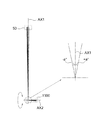
図1は、本発明の一実施形態の受光光学系1000及び被検物50を示す図である。被検物50の中心と受光光学系1000の基準点を結ぶ直線を軸AX1と呼称する。被験物50上の点から受光光学系1000に到達する光線は、軸AX1に対して、±a°の角度範囲の所定の角度をなす。上記所定の角度は、被験物50上の点の位置によって定まる。受光光学系1000は、軸AX1に所定の角度で交わり、基準点を通過する軸AX2に沿って形成される。図1は、軸AX1及び軸AX2を含む断面を示す。
FIG. 1 is a diagram showing a light receiving
図2は、本発明の一実施形態の受光光学系1000の構成を示す図である。図2は、軸AX1及び軸AX2を含む断面を示す。図2に示す受光光学系1000において、軸AX2は軸AX1と直交するように定めている。一般的に、軸AX2と軸AX1とがなす角度は、45°から135度の範囲内であるのが好ましい。受光光学系1000は、回転ミラー100と、結像光学系200と、多焦点フレネルレンズ300と、複数の集光レンズ400と複数の受光素子500と、を含む。回転ミラー100は、軸AX1及び軸AX2を含む面に直交し、該面内において軸AX2に対する角度がθ(鋭角)である反射面を含み、軸AX2の周りに回転するように構成されている。回転ミラー100が回転することによって、軸AX2の周りの被験物からの光線が受光光学系1000に到達する。軸AX2は、回転ミラー100の回転軸であるとともに、結像光学系200の光軸である。結像光学系200は、軸AX1を基準として±a°の範囲の角度の光線を、軸AX2を中心軸とする多焦点フレネルレンズ300の面上に集光させるように構成されている。
FIG. 2 is a diagram showing a configuration of a light receiving
図3は、多焦点フレネルレンズ300の機能を説明するための図である。図3において、Wは、多焦点フレネルレンズ300の軸AX2に垂直な断面の外周を形成する円の半径を示す。
FIG. 3 is a diagram for explaining the function of the
図4は、多焦点フレネルレンズ300の軸AX2に垂直な断面を示す図である。多焦点フレネルレンズ300は、軸AX2の周りに同心状に形成された複数の領域301、302、303、304及び305を含む。これらの領域は輪帯とも呼称する。
FIG. 4 is a view showing a cross section of the
図5は、被検物50からの光線の光路を示す図である。結像光学系200は、軸AX1に沿って進行する光線L1が、上述のように、多焦点フレネルレンズ300の軸AX2に垂直な断面の外周を形成する円の中心と円周との中間点(輪帯303内)を通過するように構成される。さらに、結像光学系200は、軸AX1に対して+a°の角度の光線が輪帯301内の、該中心に結像し、軸AX1に対して−a°の角度の光線が輪帯305内の該円周に集光するように構成される。回転ミラー100の、ある回転位置において、軸AX1に対する角度が+a°から−a°までの光線は、該中心と該円周を結ぶ線分に対応する線状の領域に集光する。後で説明するように、回転ミラー100が軸AX2の周りに回転すると、上記の線状の領域も軸AX2の周りに回転する。結局、光線は、回転ミラー100が軸AX2の周りの回転位置にかかわらず、光線の軸AX1に対する角度にしたがって定まる、いずれかの輪帯に集光される。図5において、符号301−305は、それぞれの光線が到達する輪帯を示す。
FIG. 5 is a diagram showing an optical path of a light ray from the subject 50. In the imaging
なお、それぞれの輪帯の幅を同じにする必要はない。光線の軸AX1に対する角度の範囲の定め方にしたがってそれぞれの輪帯の幅を定めればよい。 It is not necessary to make the width of each ring band the same. The width of each ring zone may be determined according to the method of determining the range of angles with respect to the axis AX1 of the light beam.
図6は、多焦点フレネルレンズ300のいずれかの輪帯に対応する仮想レンズを説明するための図である。仮想レンズは、球面、非球面、自由曲面などの連続面のレンズ、フレネルレンズ、回折格子のいずれによって実現することもできる。軸AX2に平行に進行する光線が仮想レンズを通過した後に進行する方向を仮想レンズの光軸とする。そこで、それぞれの輪帯に対応する仮想レンズの光軸を受光素子または集光レンズの方向に向けると、その輪帯に入射する光線のうち、軸AX2に対して平行に近い光線は、複数の集光レンズのいずれか、または複数の受光素子のいずれかに向けることができる。
FIG. 6 is a diagram for explaining a virtual lens corresponding to any ring band of the
図7は、多焦点フレネルレンズ300のいずれかの輪帯の仮想レンズの光軸OPを示す図である。
FIG. 7 is a diagram showing the optical axis OP of the virtual lens of any of the ring bands of the
図8は、回転ミラー100、結像光学系200、多焦点フレネルレンズ300を含む光学系の構成を示す図である。結像光学系200は、第1のレンズ201、第2のレンズ203、第3のレンズ205、バンドパスフィルター207を含む。バンドパスフィルター207は、受光素子が使用する波長の光のみを透過させる。一般的に、多層膜のバンドパスフィルターを使用する場合は入射角によって透過率が変わってしまうため、光線入射角の小さくなる場所に挿入するのが良い。さらに、バンドパスフィルター207と多焦点フレネルレンズ300との間にアパーチャ(開口絞り)250を備えてもよい。
FIG. 8 is a diagram showing a configuration of an optical system including a
図9は、アパーチャ250の開口部251を示す図である。
FIG. 9 is a diagram showing an
照明系によって、受光光学系1000の受光範囲よりも広い部分が照明される場合がある。この場合、結像光学系200と多焦点フレネルレンズ300の間にアパーチャ250を配置し、受光光学系1000に必要な光のみを通過させるようにしたうえで、回転ミラー100に同期させて軸AX2のまわりにアパーチャ250を回転させると、受光光学系1000に不要な光はアパーチャ250によって遮られ、受光光学系1000に必要な光のみが多焦点フレネルレンズ300を通って受光素子上に導かれる。
Depending on the illumination system, a portion wider than the light receiving range of the light receiving
また、回転ミラー100とともに、結像光学系200も回転させてもよい。結像光学系200の光軸と回転軸は軸AX2であるので、回転させた場合でも性能は変化しないので、アパーチャ250を回転させる場合には機構的に有利となる。
Further, the imaging
ここで、回転ミラー100の軸AX2の周りの回転について説明する。
Here, the rotation of the
図10は、回転ミラー100がある回転角度の場合の、集光レンズを使用しない受光光学系の光路を示す図である。
FIG. 10 is a diagram showing an optical path of a light receiving optical system that does not use a condenser lens when the
図11は、回転ミラー100が図10の状態から時計回りに90度回転した場合の、集光レンズを使用しない受光光学系の光路を示す図である。
FIG. 11 is a diagram showing an optical path of a light receiving optical system that does not use a condenser lens when the
図12は、回転ミラー100が図11の状態から時計回りに90度回転した場合の、集光レンズを使用しない受光光学系の光路を示す図である。
FIG. 12 is a diagram showing an optical path of a light receiving optical system that does not use a condenser lens when the
図13は、回転ミラー100が図12の状態から時計回りに90度回転した場合の、集光レンズを使用しない受光光学系の光路を示す図である。
FIG. 13 is a diagram showing an optical path of a light receiving optical system that does not use a condenser lens when the
図10乃至図13に示すように、回転ミラー100の回転角度にかかわらず、光線は、光線の軸AX1に対する角度にしたがって定まる、受光素子501乃至505のいずれかに到達する。
As shown in FIGS. 10 to 13, the light ray reaches any of the
図14は、回転ミラー100がある回転角度の場合の、集光レンズ401−405を使用する受光光学系の光路を示す図である。
FIG. 14 is a diagram showing an optical path of a light receiving optical system using a condenser lens 401-405 when the
図15は、回転ミラー100が図14の状態から時計回りに90度回転した場合の、集光レンズ401−405を使用する受光光学系の光路を示す図である。
FIG. 15 is a diagram showing an optical path of a light receiving optical system using a condenser lens 401-405 when the
図16は、回転ミラー100が図15の状態から時計回りに90度回転した場合の、集光レンズ401−405を使用する受光光学系の光路を示す図である。
FIG. 16 is a diagram showing an optical path of a light receiving optical system using a condenser lens 401-405 when the
図17は、回転ミラー100が図16の状態から時計回りに90度回転した場合の、集光レンズ401−405を使用する受光光学系の光路を示す図である。
FIG. 17 is a diagram showing an optical path of a light receiving optical system using a condenser lens 401-405 when the
図14乃至図17に示すように、回転ミラー100の回転角度にかかわらず、光線は、光線の軸AX1に対する角度にしたがって定まる、集光レンズ401乃至405のいずれかに到達する。
As shown in FIGS. 14 to 17, the light ray reaches any of the
要約すると、被験物50から受光光学系1000に入射する光線の、受光光学系1000の中心軸AX1に対する角度(−a°から+a°の範囲)によって、該光線が、多焦点フレネルレンズ300のどの輪帯に入射するかが決まる。さらに、いずれかの輪帯に入射した光線は、該輪帯に対応する受光素子、または集光レンズに到達する。このようにして、被験物50から受光光学系1000に入射する光線の、受光光学系1000の中心軸AX1に対する角度によって、該光線が到達する受光素子を定めることができる。この場合、光線が到達する受光素子は、回転ミラー100の回転に無関係に、受光光学系1000の中心軸AX1に対する該光線の角度のみによって定まる。したがって、受光光学系1000において、受光素子を回転させる必要がない。
In summary, depending on the angle (range of −a ° to + a °) of the light beam incident on the light receiving
つぎに、受光光学系1000について検討する。
Next, the light receiving
最初に、結像光学系200ついて検討する。結像光学系200は、像側テレセントリックであることが好ましい。像側テレセントリックである場合、結像位置が光軸方向にずれた場合においても像高が変わらないので、多焦点フレネルレンズ300上での位置が変わらないためである。
First, the imaging
結像光学系200の半画角θと像高y、焦点距離fの関係は、y=fθであることがフレネルレンズの設計が簡便となり好ましいが、その他の関係であってもかまわない。本明細書の説明においては、y=fθとする。
Regarding the relationship between the half angle of view θ of the imaging
結像光学系の入射瞳径をD、F値をF、1輪帯に入射する光線の角度範囲(分解能)のうち、最小の値をα、αの範囲に対応する、受光素子に光を導く多焦点フレネルレンズ300の輪帯幅をwとすると、以下の式が成り立つ。
w=fα (1)
F=f/D (2)
The entrance pupil diameter of the imaging optical system is D, the F value is F, and the smallest value in the angular range (resolution) of the light rays incident on the one-wheel band corresponds to the range of α and α. Assuming that the ring width of the lead
w = fα (1)
F = f / D (2)
受光光学系1000において、物体が遠距離の位置にある場合でも近距離の位置にある場合でも分解能が変わらず受光できることが好ましい。つまり、結像光学系200において、被写界深度を深くする必要がある。結像光学系200の許容錯乱円直径をδ、ベストピントでの入射瞳位置と物体間の距離をLp、後方被写界深度をLr、前方被写界深度をLfとすると、Lr、及びLfは、以下の式で表すことができる。

遠距離まで受光できるようにするには、後方被写界深度Lrを無限大にする必要がある。つまり、後方被写界深度Lrの分母が0になるようにすればよいので、以下の条件を満たせばよい。
Ln=Lp-Lf=Lp/2
となる。
The rear depth of field Lr must be infinite in order to be able to receive light over a long distance. That is, since the denominator of the rear depth of field Lr may be set to 0, the following conditions may be satisfied.
Ln = Lp-Lf = Lp / 2
Will be.
ここで、許容錯乱円直径δが多焦点フレネルレンズ300の輪帯幅の半分程度であれば、良好に輪帯に入る光線を分離することができるため、以下の関係が満たされるのが望ましい。
δ≦w/2 (6)
式(1)、式(2)、式(5)、及び式(6)から、
Lp≧2D/α
となるので、
D≦αLn (7)
となる。
Here, if the permissible circle of confusion diameter δ is about half the width of the annulus of the
δ ≤ w / 2 (6)
From equations (1), (2), (5), and (6),
Lp ≧ 2D / α
Because it becomes
D ≤ α Ln (7)
Will be.
他方、結像光学系のエアリーディスク直径をε、使用波長をλとすると、以下の関係が成立する。
ε=2.44λf/D
光の干渉によってエアリーディスク直径ε以下の径には集光できないが、許容錯乱円直径δとエアリーディスク直径εが同程度の場合には、被写界深度の範囲内では集光スポット径がほとんど変わらないことになる。よって、多焦点フレネルレンズ300の輪帯での光線の分離を考えると、ε≦w/2とするのがよい。
On the other hand, if the Airy disk diameter of the imaging optical system is ε and the wavelength used is λ, the following relationship holds.
ε = 2.44λf / D
It is not possible to collect light to a diameter smaller than the Airy disk diameter ε due to light interference, but when the permissible circle of confusion diameter δ and the Airy disk diameter ε are about the same, the focusing spot diameter is almost within the range of the depth of view. It will not change. Therefore, considering the separation of light rays in the ring zone of the
したがって、式(1)及び式(7)と組み合わせて、以下の関係が成立する必要がある。
4.88λ/α≦D≦αLn (8)
ここから、Dに解が存在ためには、以下の関係が成立する必要がある。
![]()
4.88 λ / α ≤ D ≤ α Ln (8)
From this, in order for D to have a solution, the following relationship must be established.
![]()
つぎに、多焦点フレネルレンズ300、及び受光素子500について検討する。最初に、集光レンズ400を使用しない場合について検討する。
Next, the
多焦点フレネルレンズ300のある一つの輪帯において、結像光学系200からの光線が受光素子上に入射するように仮想レンズを定める必要がある。このとき、結像光学系からの光線はFによって決まる角度の幅を持っており、光軸に対する光線の最大角度をβとすると、以下の関係が成立する。
![]()
rd≧Ld・tanβ (11)
In one ring of the
![]()
r d ≧ L d · tan β (11)
他方、輪帯上の光線を1つの受光素子上に集めるためには、Ldは少なくともその輪帯の最大直径よりも長くする必要があり、実際の多焦点フレネルレンズを考えると、多焦点フレネルレンズの半径Wと、最も光軸から遠い受光素子の中心と光軸との距離Pdの和よりも長くするのがよい。その理由は、Ldを短くすると、フレネルレンズ形状の接線角が大きくなりすぎ、加工が難しくなるからである。したがって、以下の関係を満たすのが好ましい。
W=fαmax=DFαmax (14)
式(13)及び式(14)から、以下の関係を満たすのが好ましい。
W = fα max = DFα max (14)
From the formula (13) and the formula (14), it is preferable to satisfy the following relationship.
つぎに、集光レンズ400を使用する場合について検討する。集光レンズを使用する場合、集光レンズによって狭い領域に光を集めることができるので、受光面上での単位面積当たりの光量を大きくすることができる。さらに、受光素子の受光面のサイズを集光レンズが無い場合に比べて小さくすることができる。このとき、各受光素子に対して集光レンズが必要となり、複数の受光素子に対応する複数の集光レンズ400を配置するためには、複数の受光素子500間の間隔を大きくする必要がある。したがって、他の理由により、複数の受光素子500間の間隔を大きくする必要がある場合には、複数の集光レンズ400を備えた上記の構成が適している。
Next, a case where the
複数の集光レンズ400を備えた場合に、式(16)において、受光素子の半径rdを集光レンズの最大半径rcに置き換えて、以下の関係を満たすのが好ましい。
つぎに、本発明の実施例について説明する。以下の実施例においては、設計波長λを1064[nm]とし、多焦点フレネルレンズの輪帯の数は5とし、各輪帯の幅は同じとした。また、近点距離Lnは、510[mm]とした。 Next, examples of the present invention will be described. In the following examples, the design wavelength λ is 1064 [nm], the number of ring bands of the multifocal Fresnel lens is 5, and the width of each ring band is the same. The perigee distance Ln was set to 510 [mm].
なお、以下の複数の実施例の説明において、たとえば、結像光学系、多焦点フレネルレンズがそれぞれ異なる場合でも、同じ符号200、300を使用している。
In the following description of the plurality of examples, the
実施例1
実施例1において、多焦点フレネルレンズ300のそれぞれの輪帯は連続面によって構成され、受光光学系は集光レンズを備えていない。
Example 1
In the first embodiment, each ring band of the
結像光学系200の入射瞳径D、1輪帯に入射する光線の角度範囲α、結像光学系で受光可能な半画角の最大値をαmax、輪帯幅w、多焦点フレネルレンズの半径W、受光素子の半径rd、及び最も軸AX2から遠い受光素子の中心と軸AX2との距離Pdを以下のように定めた。
D=2.2[mm]
α=0.25[deg]= 4.363E-03[rad]
αmax=1.25[deg]
w=0.6[mm]
W=3.0[mm]
rd=0.25[mm]
Pd=1.5[mm]
The entrance pupil diameter D of the imaging
D = 2.2 [mm]
α = 0.25 [deg] = 4.363E-03 [rad]
αmax = 1.25 [deg]
w = 0.6 [mm]
W = 3.0 [mm]
r d = 0.25 [mm]
P d = 1.5 [mm]
このとき、式(9)の右辺は、3.191E-03であるので、式(9)は満たされる。 At this time, since the right side of the equation (9) is 3.191E-03, the equation (9) is satisfied.
また、式(16)の左辺は 0.048[mm]であり、式(16)の右辺は 0.333[mm]であるので、式(16)は満たされる。 Further, since the left side of the equation (16) is 0.048 [mm] and the right side of the equation (16) is 0.333 [mm], the equation (16) is satisfied.
上記の仕様を満たす結像光学系200を以下のように定めた。ここで、ベストピントでの入射瞳位置と物体間の距離をLp 及び近点距離Lnは、以下のとおりである。
Lp=2Ln=1020[mm]
また、結像光学系200と多焦点フレネルレンズ300の間にλの波長を透過するバンドパスフィルター207を挿入した。
The imaging
Lp = 2Ln = 1020 [mm]
Further, a
表1は、結像光学系200のデータを示す表である。表1における長さの単位はミリメートルである。
表1の最も左側の列の数字1−6は、それぞれ、図8におけるレンズ201の入側面及び出側面、レンズ203の入側面及び出側面、レンズ205の入側面及び出側面を示す。これらの面は、結像光学系200の光軸AX2とそれぞれの面との交点をそれぞれの面定義中心として、以下の式で表せる。
表1の最も左側の列のBPFは、バンドパスフィルター207を示す。
The BPF in the leftmost column of Table 1 shows the
表1の最も上の行のRは、上記の式のcの逆数に相当し、面定義中心における曲率半径を示す。kは、上記の式のkに相当し、コーニック定数を示す。A4及びA6は、上記の式のAiの値を示す。また、dは、面間の距離を示す。たとえば、物体の行のdの数値は、物体から絞りまでの距離を示し、絞りの行のdの数値は、絞りからレンズ201の入側面までの距離を示す。絞りの行のdの数値は、0であるので、絞りはレンズ201の入側面上にある。
The R in the top row of Table 1 corresponds to the reciprocal of c in the above equation and indicates the radius of curvature at the surface definition center. k corresponds to k in the above equation and indicates a conic constant. A 4 and A 6 indicate the value of A i in the above equation. Further, d indicates the distance between the surfaces. For example, numerical values of d line of objects, indicate the distance to the aperture from the object, the numerical value of d of the aperture row indicates the distance from the diaphragm to the entrance face of the
表2は、多焦点フレネルレンズ300のそれぞれの輪帯の面形状のデータを示す表である。表2における長さの単位はミリメートルである。
表2の最も上の行の数字1−5は、それぞれの輪帯を示し、それぞれ、図4の301−305に相当する。 The numbers 1-5 in the top row of Table 2 indicate the respective annulus and correspond to 301-305 in FIG. 4, respectively.
多焦点フレネルレンズ300のそれぞれの輪帯の面は、以下の式で表せる。屈折率は1.521とした。
表2の最も左側の列のRは、上記の式のcの逆数に相当し、面定義中心における曲率半径を示す。kは、上記の式のkに相当し、コーニック定数を示す。A00及びA01は、上記の式のAmnの値を示す。rminは、それぞれの輪帯の内側の境界をなす円周の光軸AX2からの距離を表し、rmaxは、それぞれの輪帯の外側の境界をなす円周の光軸AX2からの距離を表す。 R in the leftmost column of Table 2 corresponds to the reciprocal of c in the above equation and indicates the radius of curvature at the center of the plane definition. k corresponds to k in the above equation and indicates a conic constant. A 00 and A 01 indicate the value of A mn in the above equation. rmin represents the distance from the optical axis AX2 of the circumference forming the inner boundary of each ring zone, and rmax represents the distance from the optical axis AX2 of the circumference forming the outer boundary of each ring zone.
表3は、多焦点フレネルレンズ300の受光素子側の面の面形状のデータを示す表である。表3における長さの単位はミリメートルである。
表3の最も左側の列のRは、面定義中心における曲率半径を示す。kはコーニック定数を表し、0であるので面は球面である。tは、フレネル面の面定義中心から受光素子400側の面の面定義中心までの距離を表す。
The R in the leftmost column of Table 3 indicates the radius of curvature at the center of the plane definition. Since k represents a conic constant and is 0, the surface is spherical. t represents the distance from the surface definition center of the Fresnel surface to the surface definition center of the surface on the
このようにすると、結像光学系の集光位置(像面)から受光素子までの光路長の最大値Ldを21.508[mm]として、0.75[mm]間隔でy軸方向に直線状に配列された半径rd=0.25[mm]の受光素子にそれぞれの輪帯を通過した光線を入射させることができる。 In this way, the maximum value L d of the optical path length from the condensing position (image plane) of the imaging optical system to the light receiving element is 21.508 [mm], and they are arranged linearly in the y-axis direction at 0.75 [mm] intervals. A light ray passing through each annulus can be incident on a light receiving element having a radius of rd = 0.25 [mm].
図18は、結像光学系の集光位置と集光位置からの光路長が最大値Ldを示す最も離れた受光素子とを示す図である。 FIG. 18 is a diagram showing a condensing position of the imaging optical system and the farthest light receiving element in which the optical path length from the condensing position shows the maximum value L d .
受光光学系1000の中心軸AX1が、結像光学系200の光軸AX2に垂直になるように設定し、このとき軸AX1に沿って進行する光線が多焦点フレネルレンズ300の、軸AX2から半径Wの半分W/2離れた位置を通るように回転ミラー100の軸AX2に対する角度θを45.3125[deg]とした。このとき軸AX1から+0.625[deg]の方向からの光線は、結像光学系200を通って多焦点フレネルレンズ300の中心を通り、受光素子501に向かう。また、軸AX1から-0.625[deg]の方向からの光線は、多焦点フレネルレンズ300の光学領域の外周を通り、受光素子505に向かう。
The central axis AX1 of the light receiving
以上の構成にすると、軸AX1に対して+0.625[deg]〜+0.375[deg]の範囲の光線は多焦点フレネルレンズ300の輪帯301を通って受光素子501に入る。同様に、軸AX1に対して+0.375[deg]〜+0.125[deg] の範囲の光線は輪帯302を通って受光素子502に、軸AX1に対して+0.125[deg]〜-0.125[deg] の範囲の光線は輪帯303を通って受光素子503に、軸AX1に対して-0.125 [deg]〜-0.375[deg] の範囲の光線は輪帯304を通って受光素子504に、軸AX1に対して-0.375 [deg]〜-0.625[deg] の範囲の光線は輪帯305を通って受光素子505に入る。
With the above configuration, light rays in the range of +0.625 [deg] to +0.375 [deg] with respect to the axis AX1 pass through the
実施例2
実施例2において、多焦点フレネルレンズ300のそれぞれの輪帯が連続面によって構成され、受光光学系は集光レンズを備えている。
Example 2
In the second embodiment, each ring band of the
結像光学系200の入射瞳径D、1輪帯に入射する光線の角度範囲α、結像光学系で受光可能な半画角の最大値をαmax、輪帯幅w、多焦点フレネルレンズの半径W、集光レンズの半径rc、受光素子の半径rd、及び最も軸AX2から遠い受光素子の中心と軸AX2との距離Pdを以下のように定めた。
D=4.0[mm]
α=0.45[deg]= 7.8540E-03[rad]
αmax=2.25[deg]
w=0.66[mm]
W=3.3[mm]
rc=3.0[mm]
rd=0.25[mm]
Pd=12.0[mm]
The entrance pupil diameter D of the imaging
D = 4.0 [mm]
α = 0.45 [deg] = 7.8540E-03 [rad]
αmax = 2.25 [deg]
w = 0.66 [mm]
W = 3.3 [mm]
rc = 3.0 [mm]
r d = 0.25 [mm]
P d = 12.0 [mm]
このとき、式(9)の右辺は、3.191E-03であるので、式(9)は満たされる。 At this time, since the right side of the equation (9) is 3.191E-03, the equation (9) is satisfied.
また、式(17)の左辺は 0.157[mm]であり、式(17)の右辺は 1.270[mm]であるので、式(17)は満たされる。 Further, since the left side of the equation (17) is 0.157 [mm] and the right side of the equation (17) is 1.270 [mm], the equation (17) is satisfied.
上記の仕様を満たす結像光学系200を以下のように定めた。ここで、ベストピントでの入射瞳位置と物体間の距離をLp 及び近点距離Lnは、以下のとおりである。
Lp=2Ln=1020[mm]
また、結像光学系200と多焦点フレネルレンズ300の間にλの波長を透過するバンドパスフィルター207を挿入した。
The imaging
Lp = 2Ln = 1020 [mm]
Further, a
表4A及び表4Bは、結像光学系200のデータを示す表である。表4A及び表4Bにおける長さの単位はミリメートルである。
表4A及び表4Bの最も左側の列の数字1−6は、それぞれ、図8におけるレンズ201の入側面及び出側面、レンズ203の入側面及び出側面、レンズ205の入側面及び出側面を示す。これらの面は、結像光学系200の光軸AX2とそれぞれの面との交点をそれぞれの面定義中心として、以下の式で表せる。
表4A及び表4Bの最も左側の列のBPFは、バンドパスフィルター207を示す。
The BPF in the leftmost column of Tables 4A and 4B indicates the
表4A及び表4Bの最も上の行のRは、上記の式のcの逆数に相当し、面定義中心における曲率半径を示す。kは、上記の式のkに相当し、コーニック定数を示す。A4、A6及びA8は、上記の式のAiの値を示す。また、dは、面間の距離を示す。たとえば、物体の行のdの数値は、物体から絞りまでの距離を示し、絞りの行のdの数値は、絞りからレンズ201の入側面までの距離を示す。絞りの行のdの数値は、0であるので、絞りはレンズ201の入側面上にある。
The R in the top row of Tables 4A and 4B corresponds to the reciprocal of c in the above equation and indicates the radius of curvature at the surface definition center. k corresponds to k in the above equation and indicates a conic constant. A 4 , A 6 and A 8 indicate the value of A i in the above equation. Further, d indicates the distance between the surfaces. For example, numerical values of d line of objects, indicate the distance to the aperture from the object, the numerical value of d of the aperture row indicates the distance from the diaphragm to the entrance face of the
表5は、多焦点フレネルレンズ300のそれぞれの輪帯の面形状のデータを示す表である。表5における長さの単位はミリメートルである。
表5の最も上の行の数字1−5は、それぞれの輪帯を示し、それぞれ、図4の301−305に相当する。 The numbers 1-5 in the top row of Table 5 indicate the respective annulus and correspond to 301-305 in FIG. 4, respectively.
多焦点フレネルレンズ300のそれぞれの輪帯の面は、以下の式で表せる。屈折率は1.521とした。
表5の最も左側の列のRは、上記の式のcの逆数に相当し、面定義中心における曲率半径を示す。kは、上記の式のkに相当し、コーニック定数を示す。A00及びA01は、上記の式のAmnの値を示す。rminは、それぞれの輪帯の内側の境界をなす円周の光軸AX2からの距離を表し、rmaxは、それぞれの輪帯の外側の境界をなす円周の光軸AX2からの距離を表す。 The R in the leftmost column of Table 5 corresponds to the reciprocal of c in the above equation and indicates the radius of curvature at the center of the plane definition. k corresponds to k in the above equation and indicates a conic constant. A 00 and A 01 indicate the value of A mn in the above equation. rmin represents the distance from the optical axis AX2 of the circumference forming the inner boundary of each ring zone, and rmax represents the distance from the optical axis AX2 of the circumference forming the outer boundary of each ring zone.
また、受光素子側の面は平面とし、フレネル面の面定義中心から受光素子側の面の面定義中心までの距離tは1.5[mm]とした。 The surface on the light receiving element side was flat, and the distance t from the surface definition center on the Frenel surface to the surface definition center on the light receiving element side was 1.5 [mm].
表6は、多焦点フレネルレンズ300の5個の輪帯に対応する5個の集光レンズのデータを示す表である。表6における長さの単位はミリメートルである。
表6の最も上の行の数字1−5は、それぞれの集光レンズを示し、それぞれ、図14−17の401−405に相当する。 The numbers 1-5 in the top row of Table 6 indicate the respective condenser lenses, which correspond to 401-405 in FIG. 14-17, respectively.
軸AX2と像面との交点を原点として、像面内に互いに直交するx軸及びy軸を定める。また、軸AX2をz軸とする。 With the intersection of the axis AX2 and the image plane as the origin, the x-axis and y-axis that are orthogonal to each other are determined in the image plane. Further, the axis AX2 is defined as the z-axis.
集光レンズの多焦点フレネルレンズ側の面をS1面、受光素子側の面をS2面とする。 The surface of the condensing lens on the multifocal Fresnel lens side is the S1 surface, and the surface on the light receiving element side is the S2 surface.
表6の最も左側の列において、dzは像面から各集光レンズのS1面の面定義中心までのz方向距離[mm] 、dyは軸AX2からS1面の面定義中心までのy軸方向距離[mm]、txは集光レンズの中心軸と軸AX2との角度[deg]、tcは集光レンズの芯厚[mm]をそれぞれ示す。ここで、それぞれの集光レンズは、その中心軸が、対応する輪帯の仮想レンズの光軸と一致するように配置される。
In the leftmost column of Table 6, dz is the z-direction distance [mm] from the image plane to the surface definition center of the S1 surface of each condenser lens, and dy is the y-axis direction from the axis AX2 to the surface definition center of the S1 surface. distance [mm], tx is the angle between the mandrel and the axis AX2 in the condenser lens [deg], tc denotes the core thickness of the condenser lens [mm], respectively. Here, each of the condenser lenses, central axis in the its is arranged to coincide with the optical axis of the virtual lens corresponding annular.
S1面及びS2面は、以下の式で表せる。
表6の最も左側の列におけるRは、上記の式のcの逆数に相当し、面定義中心における曲率半径を示す。kは、上記の式のkに相当し、コーニック定数を示す。A4及びA6は、上記の式のAiの値を示す。 R in the leftmost column of Table 6 corresponds to the reciprocal of c in the above equation and indicates the radius of curvature at the surface definition center. k corresponds to k in the above equation and indicates a conic constant. A 4 and A 6 indicate the value of A i in the above equation.
このようにすると、結像光学系の集光位置(像面)から集光レンズまでの光路長の最大値Ldを73.572[mm]として、6.0[mm]間隔でy軸方向に直線状に配列された受光素子にそれぞれの輪帯を通過した光線を入射させることができる。 In this way, the maximum value L d of the optical path length from the condensing position (image plane) of the imaging optical system to the condensing lens is 73.572 [mm], and the light path is linear at intervals of 6.0 [mm] in the y-axis direction. Light rays that have passed through the respective ring zones can be incident on the arranged light receiving elements.
軸AX1が、結像光学系200の光軸AX2に垂直になるように設定し、このとき軸AX1に沿って進行する光線が多焦点フレネルレンズ300の、軸AX2から半径Wの半分W/2離れた位置を通るように回転ミラー100の軸AX2に対する角度θを45.5625[deg]とした。このとき軸AX1から+1.125 [deg]の方向からの光線は、結像光学系200を通って多焦点フレネルレンズ300の中心を通り、受光素子501に向かう。また、軸AX1から-1.125 [deg]の方向からの光線は、多焦点フレネルレンズ300の光学領域の外周を通り、受光素子505に向かう。
The axis AX1 is set to be perpendicular to the optical axis AX2 of the imaging
以上の構成にすると、軸AX1に対して+1.125 [deg]〜+0.675[deg]の範囲の光線は多焦点フレネルレンズ300の輪帯301を通って受光素子501に入る。同様に、軸AX1に対して+0.675 [deg]〜+0.225 [deg] の範囲の光線は輪帯302を通って受光素子502に、軸AX1に対して+0.225 [deg]〜-0.225 [deg] の範囲の光線は輪帯303を通って受光素子503に、軸AX1に対して-0.225 [deg]〜-0.675 [deg] の範囲の光線は輪帯304を通って受光素子504に、軸AX1に対して-0.675 [deg]〜-1.125 [deg] の範囲の光線は輪帯305を通って受光素子505に入る。
With the above configuration, light rays in the range of +1.125 [deg] to +0.675 [deg] with respect to the axis AX1 pass through the
実施例3
実施例3の受光光学系は、多焦点フレネルレンズを除いて実施例1の受光光学系と同じである。実施例3の多焦点フレネルレンズのそれぞれの輪帯は、フレネル形状とした。こうすることにより、フレネル面側の全体的なサグ量を小さくし、多焦点フレネルレンズを薄くすることができる。
Example 3
The light receiving optical system of Example 3 is the same as the light receiving optical system of Example 1 except for the multifocal Fresnel lens. Each annulus of the multifocal Fresnel lens of Example 3 has a Fresnel shape. By doing so, the overall sag amount on the Fresnel surface side can be reduced, and the multifocal Fresnel lens can be made thinner.
表7は、多焦点フレネルレンズ300のそれぞれの輪帯の面形状のデータを示す表である。表7における長さの単位はミリメートルである。
表7の最も上の行の数字1−5は、それぞれの輪帯を示し、それぞれ、図4の301−305に相当する。それぞれの輪帯のフレネルレンズのピッチは、0.3mmとした。 The numbers 1-5 in the top row of Table 7 indicate the respective annulus and correspond to 301-305 in FIG. 4, respectively. The pitch of the Fresnel lens in each ring band was 0.3 mm.
多焦点フレネルレンズ300のそれぞれの輪帯の面形状は以下の式で表せる。屈折率は1.521とした。
表7の最も左側の列のRは、上記の式のcの逆数に相当し、面定義中心における曲率半径を示す。kは、上記の式のkに相当し、コーニック定数を示す。dyは軸AX2からそれぞれの輪帯の面の面定義中心までのy軸方向距離[mm]を示す。rminは、それぞれの輪帯の内側の境界をなす円周の光軸AX2からの距離を表し、rmaxは、それぞれの輪帯の外側の境界をなす円周の光軸AX2からの距離を表す。 The R in the leftmost column of Table 7 corresponds to the reciprocal of c in the above equation and indicates the radius of curvature at the surface definition center. k corresponds to k in the above equation and indicates a conic constant. dy indicates the y-axis direction distance [mm] from the axis AX2 to the surface definition center of the surface of each ring band. rmin represents the distance from the optical axis AX2 of the circumference forming the inner boundary of each ring zone, and rmax represents the distance from the optical axis AX2 of the circumference forming the outer boundary of each ring zone.
また、受光素子側の面は平面とし、フレネル面の面定義中心から受光素子側の面の面定義中心までの距離tは1.5[mm]とした。 The surface on the light receiving element side was flat, and the distance t from the surface definition center on the Frenel surface to the surface definition center on the light receiving element side was 1.5 [mm].
上記の実施例3の多焦点フレネルレンズによって実施例1の多焦点フレネルレンズと同様の効果が得られる。 The same effect as the multifocal Fresnel lens of Example 1 can be obtained by the multifocal Fresnel lens of Example 3 described above.
図19は、実施例3の多焦点フレネルレンズを示す図である。 FIG. 19 is a diagram showing a multifocal Fresnel lens of Example 3.
図20は、実施例3の多焦点フレネルレンズのyz断面を示す図である。上述のように、それぞれの輪帯のフレネルレンズのピッチは、0.3mmである。また、それぞれの輪帯のフレネル形状は、凸部の頂点がフレネル定義面、すなわちフレネル面の面定義中心を通り軸AX2に垂直な面と一致するように定めた。 FIG. 20 is a diagram showing a yz cross section of the multifocal Fresnel lens of Example 3. As mentioned above, the pitch of the Fresnel lens of each ring band is 0.3 mm. Further, the Fresnel shape of each ring band is determined so that the apex of the convex portion passes through the Fresnel definition plane, that is, the plane definition center of the Fresnel plane and coincides with the plane perpendicular to the axis AX2.
実施例4
実施例4の受光光学系は、多焦点フレネルレンズを除いて実施例1の受光光学系と同じである。実施例4の多焦点フレネルレンズのそれぞれの輪帯は、回折格子で形成されている。
Example 4
The light receiving optical system of Example 4 is the same as the light receiving optical system of Example 1 except for the multifocal Fresnel lens. Each annulus of the multifocal Fresnel lens of Example 4 is formed by a diffraction grating.
表8は、多焦点フレネルレンズ300のそれぞれの輪帯の面形状のデータを示す表である。表8における長さの単位はミリメートルである。
表8の最も上の行の数字1−5は、それぞれの輪帯を示し、それぞれ、図4の301−305に相当する。 The numbers 1-5 in the top row of Table 8 indicate the respective annulus and correspond to 301-305 in FIG. 4, respectively.
多焦点フレネルレンズ300のそれぞれの輪帯の回折格子の位相関数は以下の式で表せる。
表8の最も左側の列のdyは軸AX2からそれぞれの輪帯の面の面定義中心までのy軸方向距離[mm]を示す。rminは、それぞれの輪帯の内側の境界をなす円周の光軸AX2からの距離を表し、rmaxは、それぞれの輪帯の外側の境界をなす円周の光軸AX2からの距離を表す。 The dy in the leftmost column of Table 8 indicates the y-axis direction distance [mm] from the axis AX2 to the surface definition center of the surface of each ring band. rmin represents the distance from the optical axis AX2 of the circumference forming the inner boundary of each ring zone, and rmax represents the distance from the optical axis AX2 of the circumference forming the outer boundary of each ring zone.
また、受光素子側の面は平面とし、フレネル面の面定義中心から受光素子側の面の面定義中心までの距離tは1.5[mm]とした。 The surface on the light receiving element side was flat, and the distance t from the surface definition center on the Frenel surface to the surface definition center on the light receiving element side was 1.5 [mm].
上記の実施例4の多焦点フレネルレンズによって実施例1の多焦点フレネルレンズと同様の効果が得られる。
The same effect as the multifocal Fresnel lens of Example 1 can be obtained by the multifocal Fresnel lens of Example 4 described above.
Claims (9)
被検物からの光線が、該光軸に垂直な断面において、該光軸と該多焦点フレネルレンズの外周を結ぶ線分に対応する線状の領域に集光する状態で機能し、
該多焦点フレネルレンズは、該光軸の周りに同心状に形成された複数の領域を備え、該線分と該光軸とを含む面内において該回転ミラーに入射した光線が、該光軸に対する該光線の角度に応じて、該結像光学系によって該多焦点フレネルレンズのいずれかの領域に集光された後、該複数の受光素子のうちの該いずれかの領域に対応する受光素子に到達するように構成され、該回転ミラーの回転位置にかかわらず、該光線の該光軸に対する角度に応じて該光線の到達する受光素子が定まるように構成された受光光学系。 An imaging optical system having a rotating mirror configured to rotate around a rotating axis and having a reflecting surface arranged to have a predetermined angle with respect to the rotating axis, and an optical axis matching the rotating axis. A light receiving optical system having a multifocal Fresnel lens and a plurality of light receiving elements.
The light beam from the test object functions in a state of being focused on a linear region corresponding to a line segment connecting the optical axis and the outer periphery of the multifocal Fresnel lens in a cross section perpendicular to the optical axis.
The multifocal Fresnel lens includes a plurality of regions formed concentrically around the optical axis, and light rays incident on the rotating mirror in a plane including the line segment and the optical axis are emitted by the optical axis. A light receiving element corresponding to any one of the plurality of light receiving elements after being focused on any region of the multifocal Fresnel lens by the imaging optical system according to the angle of the light ray with respect to the light beam. A light receiving optical system configured to reach the light beam, and the light receiving element to which the light ray reaches is determined according to the angle of the light ray with respect to the optical axis regardless of the rotation position of the rotating mirror.
4.88λ/α≦D≦αLn
を満たす、請求項1から3のいずれかに記載の受光光学系。 Let Δθ be the difference between the maximum value and the minimum value of the angle of the light beam focused on a certain region among the plurality of regions with respect to the optical axis, and let α be the minimum value among the plurality of Δθ of the plurality of regions. When the entrance pupil diameter of the imaging optical system is D, the near point distance which is the minimum object distance at which the point image is less than the allowable circle of confusion in the imaging system is L n , and the wavelength used is λ.
4.88 λ / α ≤ D ≤ α L n
The light receiving optical system according to any one of claims 1 to 3, which satisfies the above conditions.
Priority Applications (2)
| Application Number | Priority Date | Filing Date | Title |
|---|---|---|---|
| JP2017054393A JP6810454B2 (en) | 2017-03-21 | 2017-03-21 | Light receiving optical system |
| US15/924,808 US10527489B2 (en) | 2017-03-21 | 2018-03-19 | Light-receiving optical system |
Applications Claiming Priority (1)
| Application Number | Priority Date | Filing Date | Title |
|---|---|---|---|
| JP2017054393A JP6810454B2 (en) | 2017-03-21 | 2017-03-21 | Light receiving optical system |
Publications (3)
| Publication Number | Publication Date |
|---|---|
| JP2018156008A JP2018156008A (en) | 2018-10-04 |
| JP2018156008A5 JP2018156008A5 (en) | 2020-02-27 |
| JP6810454B2 true JP6810454B2 (en) | 2021-01-06 |
Family
ID=63581706
Family Applications (1)
| Application Number | Title | Priority Date | Filing Date |
|---|---|---|---|
| JP2017054393A Active JP6810454B2 (en) | 2017-03-21 | 2017-03-21 | Light receiving optical system |
Country Status (2)
| Country | Link |
|---|---|
| US (1) | US10527489B2 (en) |
| JP (1) | JP6810454B2 (en) |
Families Citing this family (4)
| Publication number | Priority date | Publication date | Assignee | Title |
|---|---|---|---|---|
| JP6810454B2 (en) * | 2017-03-21 | 2021-01-06 | ナルックス株式会社 | Light receiving optical system |
| JP6788537B2 (en) * | 2017-03-28 | 2020-11-25 | 本田技研工業株式会社 | Object edge detection method using a laser ranging device |
| JP7103694B2 (en) * | 2020-01-24 | 2022-07-20 | 株式会社コムテック | Laser detector |
| KR20230000670A (en) * | 2021-06-25 | 2023-01-03 | 주식회사 세코닉스 | Lens systen for Lidar |
Family Cites Families (16)
| Publication number | Priority date | Publication date | Assignee | Title |
|---|---|---|---|---|
| JPH0658481B2 (en) * | 1985-02-22 | 1994-08-03 | 株式会社ニコン | Multifocal Fresnel lens for camera focus plate |
| JP3356576B2 (en) * | 1994-02-25 | 2002-12-16 | 日本電気株式会社 | Laser radar |
| JPH07270602A (en) * | 1994-03-31 | 1995-10-20 | Omron Corp | Lens for receiving light, light receiving device, photoelectric sensor and laser radar using them and vehicle loading laser radar |
| JPH0882677A (en) * | 1994-09-13 | 1996-03-26 | Nippondenso Co Ltd | Reflection measuring apparatus |
| JP3340885B2 (en) * | 1995-07-04 | 2002-11-05 | 株式会社デンソー | Reflection measuring device |
| JP2007501410A (en) * | 2003-02-10 | 2007-01-25 | ユニヴァースティ オブ ヴァージニア パテント ファウンデイション | System and method for remote sensing and / or analysis to detect and / or identify spectral characteristics of targets and / or chemical species |
| JP2004247947A (en) * | 2003-02-13 | 2004-09-02 | Olympus Corp | Optical apparatus |
| JP4702200B2 (en) * | 2006-06-27 | 2011-06-15 | 株式会社デンソー | RECEIVER AND RADAR DEVICE PROVIDED WITH THE RECEIVER |
| JP5177003B2 (en) * | 2009-02-19 | 2013-04-03 | 株式会社デンソーウェーブ | Laser distance measuring device |
| WO2011046034A1 (en) * | 2009-10-15 | 2011-04-21 | 日本電気株式会社 | Image projection device, image projection method and image display device |
| JP5919530B2 (en) * | 2010-12-21 | 2016-05-18 | パナソニックIpマネジメント株式会社 | Optical detection device and apparatus using the same |
| JP2013072770A (en) * | 2011-09-28 | 2013-04-22 | Denso Wave Inc | Laser radar apparatus |
| JP2013200367A (en) * | 2012-03-23 | 2013-10-03 | Panasonic Corp | Fresnel lens and optical detector |
| EP2856240A4 (en) * | 2012-04-26 | 2016-03-02 | Neptec Design Group Ltd | High speed 360 degree scanning lidar head |
| US20140211194A1 (en) | 2013-01-27 | 2014-07-31 | Quanergy Systems, Inc. | Cost-effective lidar sensor for multi-signal detection, weak signal detection and signal disambiguation and method of using same |
| JP6810454B2 (en) * | 2017-03-21 | 2021-01-06 | ナルックス株式会社 | Light receiving optical system |
-
2017
- 2017-03-21 JP JP2017054393A patent/JP6810454B2/en active Active
-
2018
- 2018-03-19 US US15/924,808 patent/US10527489B2/en active Active
Also Published As
| Publication number | Publication date |
|---|---|
| JP2018156008A (en) | 2018-10-04 |
| US10527489B2 (en) | 2020-01-07 |
| US20180274972A1 (en) | 2018-09-27 |
Similar Documents
| Publication | Publication Date | Title |
|---|---|---|
| JP6810454B2 (en) | Light receiving optical system | |
| US6856466B2 (en) | Multiple imaging system | |
| US7268956B2 (en) | Solid catadioptric lens with two viewpoints | |
| US6611282B1 (en) | Super wide-angle panoramic imaging apparatus | |
| JP4195292B2 (en) | Imaging system using catadioptric system and catadioptric system | |
| JP4611111B2 (en) | Optical system | |
| JP2004348041A (en) | Eccentric optical system and optical device using the same | |
| JP2006235139A (en) | Optical system for focusing two wavelengths | |
| EP3084373B1 (en) | Spectrometer for generating a two dimensional spectrum | |
| JP2003515733A (en) | Concentric spectrometer to reduce internal specular reflection | |
| JP2016038574A (en) | Imaging optical system | |
| US11852852B2 (en) | Patterned mirror edge for stray beam and interference mitigation | |
| JPH02157808A (en) | Radiation beam converging apparatus | |
| EP2382501A2 (en) | Combined lens and reflector, and an optical apparatus using the same | |
| CA2773965C (en) | Meso-optic device | |
| JP5452245B2 (en) | Lightwave distance measuring device | |
| US20170102233A1 (en) | Image-Forming Optical Component And Optical System Of Surveying Instrument | |
| CN109597193B (en) | Compact wide-spectrum optical system | |
| JP2010217142A (en) | Optical sensor | |
| JP6596744B2 (en) | Optical element | |
| JP2006154365A (en) | Optical system | |
| JP7264749B2 (en) | Stereo camera and stereo camera integrated light unit | |
| KR102176198B1 (en) | A Lens Assembly for a Black Box | |
| JPH04328500A (en) | Condenser | |
| CN117233929A (en) | Sub-band double-channel objective lens |
Legal Events
| Date | Code | Title | Description |
|---|---|---|---|
| A711 | Notification of change in applicant |
Free format text: JAPANESE INTERMEDIATE CODE: A711 Effective date: 20191202 |
|
| A521 | Request for written amendment filed |
Free format text: JAPANESE INTERMEDIATE CODE: A821 Effective date: 20191202 |
|
| A521 | Request for written amendment filed |
Free format text: JAPANESE INTERMEDIATE CODE: A523 Effective date: 20200114 |
|
| A621 | Written request for application examination |
Free format text: JAPANESE INTERMEDIATE CODE: A621 Effective date: 20200114 |
|
| A131 | Notification of reasons for refusal |
Free format text: JAPANESE INTERMEDIATE CODE: A131 Effective date: 20201022 |
|
| A977 | Report on retrieval |
Free format text: JAPANESE INTERMEDIATE CODE: A971007 Effective date: 20201021 |
|
| A521 | Request for written amendment filed |
Free format text: JAPANESE INTERMEDIATE CODE: A523 Effective date: 20201117 |
|
| TRDD | Decision of grant or rejection written | ||
| A01 | Written decision to grant a patent or to grant a registration (utility model) |
Free format text: JAPANESE INTERMEDIATE CODE: A01 Effective date: 20201201 |
|
| A61 | First payment of annual fees (during grant procedure) |
Free format text: JAPANESE INTERMEDIATE CODE: A61 Effective date: 20201204 |
|
| R150 | Certificate of patent or registration of utility model |
Ref document number: 6810454 Country of ref document: JP Free format text: JAPANESE INTERMEDIATE CODE: R150 |
|
| S531 | Written request for registration of change of domicile |
Free format text: JAPANESE INTERMEDIATE CODE: R313531 |
|
| R350 | Written notification of registration of transfer |
Free format text: JAPANESE INTERMEDIATE CODE: R350 |
|
| R250 | Receipt of annual fees |
Free format text: JAPANESE INTERMEDIATE CODE: R250 |