JP6809804B2 - Dustproof cap for optical transmission / reception module and optical transmission / reception module equipped with it - Google Patents
Dustproof cap for optical transmission / reception module and optical transmission / reception module equipped with it Download PDFInfo
- Publication number
- JP6809804B2 JP6809804B2 JP2016076140A JP2016076140A JP6809804B2 JP 6809804 B2 JP6809804 B2 JP 6809804B2 JP 2016076140 A JP2016076140 A JP 2016076140A JP 2016076140 A JP2016076140 A JP 2016076140A JP 6809804 B2 JP6809804 B2 JP 6809804B2
- Authority
- JP
- Japan
- Prior art keywords
- side connector
- connector portion
- optical transmission
- receiving
- transmitting
- Prior art date
- Legal status (The legal status is an assumption and is not a legal conclusion. Google has not performed a legal analysis and makes no representation as to the accuracy of the status listed.)
- Active
Links
- 230000005540 biological transmission Effects 0.000 title claims description 134
- 230000003287 optical effect Effects 0.000 title claims description 119
- 239000013307 optical fiber Substances 0.000 claims description 13
- 239000000428 dust Substances 0.000 claims description 10
- 239000011521 glass Substances 0.000 claims description 3
- 239000004033 plastic Substances 0.000 claims description 3
- 238000004140 cleaning Methods 0.000 description 4
- 239000000835 fiber Substances 0.000 description 4
- MCMNRKCIXSYSNV-UHFFFAOYSA-N Zirconium dioxide Chemical compound O=[Zr]=O MCMNRKCIXSYSNV-UHFFFAOYSA-N 0.000 description 2
- 239000000463 material Substances 0.000 description 2
- VYPSYNLAJGMNEJ-UHFFFAOYSA-N Silicium dioxide Chemical compound O=[Si]=O VYPSYNLAJGMNEJ-UHFFFAOYSA-N 0.000 description 1
- 239000000654 additive Substances 0.000 description 1
- 230000000996 additive effect Effects 0.000 description 1
- 239000011248 coating agent Substances 0.000 description 1
- 238000000576 coating method Methods 0.000 description 1
- 230000007547 defect Effects 0.000 description 1
- 230000002950 deficient Effects 0.000 description 1
- 239000002184 metal Substances 0.000 description 1
- 238000012986 modification Methods 0.000 description 1
- 230000004048 modification Effects 0.000 description 1
- 230000001902 propagating effect Effects 0.000 description 1
- 239000011347 resin Substances 0.000 description 1
- 229920005989 resin Polymers 0.000 description 1
Images


Classifications
-
- G—PHYSICS
- G02—OPTICS
- G02B—OPTICAL ELEMENTS, SYSTEMS OR APPARATUS
- G02B6/00—Light guides; Structural details of arrangements comprising light guides and other optical elements, e.g. couplings
- G02B6/24—Coupling light guides
- G02B6/36—Mechanical coupling means
- G02B6/38—Mechanical coupling means having fibre to fibre mating means
- G02B6/3807—Dismountable connectors, i.e. comprising plugs
- G02B6/3833—Details of mounting fibres in ferrules; Assembly methods; Manufacture
- G02B6/3847—Details of mounting fibres in ferrules; Assembly methods; Manufacture with means preventing fibre end damage, e.g. recessed fibre surfaces
- G02B6/3849—Details of mounting fibres in ferrules; Assembly methods; Manufacture with means preventing fibre end damage, e.g. recessed fibre surfaces using mechanical protective elements, e.g. caps, hoods, sealing membranes
-
- G—PHYSICS
- G02—OPTICS
- G02B—OPTICAL ELEMENTS, SYSTEMS OR APPARATUS
- G02B6/00—Light guides; Structural details of arrangements comprising light guides and other optical elements, e.g. couplings
- G02B6/24—Coupling light guides
- G02B6/36—Mechanical coupling means
- G02B6/38—Mechanical coupling means having fibre to fibre mating means
- G02B6/3807—Dismountable connectors, i.e. comprising plugs
- G02B6/381—Dismountable connectors, i.e. comprising plugs of the ferrule type, e.g. fibre ends embedded in ferrules, connecting a pair of fibres
- G02B6/3823—Dismountable connectors, i.e. comprising plugs of the ferrule type, e.g. fibre ends embedded in ferrules, connecting a pair of fibres containing surplus lengths, internal fibre loops
-
- G—PHYSICS
- G02—OPTICS
- G02B—OPTICAL ELEMENTS, SYSTEMS OR APPARATUS
- G02B6/00—Light guides; Structural details of arrangements comprising light guides and other optical elements, e.g. couplings
- G02B6/24—Coupling light guides
- G02B6/36—Mechanical coupling means
- G02B6/38—Mechanical coupling means having fibre to fibre mating means
- G02B6/3807—Dismountable connectors, i.e. comprising plugs
- G02B6/3833—Details of mounting fibres in ferrules; Assembly methods; Manufacture
- G02B6/385—Accessories for testing or observation of connectors
-
- G—PHYSICS
- G02—OPTICS
- G02B—OPTICAL ELEMENTS, SYSTEMS OR APPARATUS
- G02B6/00—Light guides; Structural details of arrangements comprising light guides and other optical elements, e.g. couplings
- G02B6/24—Coupling light guides
- G02B6/42—Coupling light guides with opto-electronic elements
- G02B6/4201—Packages, e.g. shape, construction, internal or external details
- G02B6/4246—Bidirectionally operating package structures
-
- G—PHYSICS
- G02—OPTICS
- G02B—OPTICAL ELEMENTS, SYSTEMS OR APPARATUS
- G02B6/00—Light guides; Structural details of arrangements comprising light guides and other optical elements, e.g. couplings
- G02B6/24—Coupling light guides
- G02B6/42—Coupling light guides with opto-electronic elements
- G02B6/4292—Coupling light guides with opto-electronic elements the light guide being disconnectable from the opto-electronic element, e.g. mutually self aligning arrangements
-
- G—PHYSICS
- G02—OPTICS
- G02B—OPTICAL ELEMENTS, SYSTEMS OR APPARATUS
- G02B6/00—Light guides; Structural details of arrangements comprising light guides and other optical elements, e.g. couplings
- G02B6/24—Coupling light guides
- G02B6/42—Coupling light guides with opto-electronic elements
- G02B6/4296—Coupling light guides with opto-electronic elements coupling with sources of high radiant energy, e.g. high power lasers, high temperature light sources
- G02B2006/4297—Coupling light guides with opto-electronic elements coupling with sources of high radiant energy, e.g. high power lasers, high temperature light sources having protection means, e.g. protecting humans against accidental exposure to harmful laser radiation
-
- G—PHYSICS
- G02—OPTICS
- G02B—OPTICAL ELEMENTS, SYSTEMS OR APPARATUS
- G02B6/00—Light guides; Structural details of arrangements comprising light guides and other optical elements, e.g. couplings
- G02B6/24—Coupling light guides
- G02B6/36—Mechanical coupling means
- G02B6/38—Mechanical coupling means having fibre to fibre mating means
- G02B6/3807—Dismountable connectors, i.e. comprising plugs
- G02B6/3873—Connectors using guide surfaces for aligning ferrule ends, e.g. tubes, sleeves, V-grooves, rods, pins, balls
- G02B6/3874—Connectors using guide surfaces for aligning ferrule ends, e.g. tubes, sleeves, V-grooves, rods, pins, balls using tubes, sleeves to align ferrules
- G02B6/3878—Connectors using guide surfaces for aligning ferrule ends, e.g. tubes, sleeves, V-grooves, rods, pins, balls using tubes, sleeves to align ferrules comprising a plurality of ferrules, branching and break-out means
Description
本発明は、光送受信モジュール用の防塵キャップ及びそれを備える光送受信モジュールに関する。 The present invention relates to a dustproof cap for an optical transmission / reception module and an optical transmission / reception module including the dustproof cap.
光送受信モジュールには、送信用及び受信用の光ファイバコネクタを挿入する2つのアダプタ(ポート、コネクタ)が隣り合って設けられている。光送受信モジュールに使用される光伝送路は、一般に石英ガラスを用いた光ファイバが使用されており、光信号を伝搬するためのコア径は、マルチモードファイバで50.0μm、もしくは62.5μm、シングルモードファイバで9.2μmと非常に小径である。そのため、ファイバコネクタに非常に微細な異物が付着しても通信不良の原因となる。そのような微細な異物の付着による通信不良を防止するため、通常、これらのアダプタには出荷時に防塵キャップが嵌め込まれている。 The optical transmission / reception module is provided with two adapters (ports and connectors) adjacent to each other for inserting optical fiber connectors for transmission and reception. An optical fiber using quartz glass is generally used for the optical transmission line used in the optical transmission / reception module, and the core diameter for propagating an optical signal is 50.0 μm or 62.5 μm in a multimode fiber. It is a single mode fiber with a very small diameter of 9.2 μm. Therefore, even if very fine foreign matter adheres to the fiber connector, it causes communication failure. In order to prevent communication failure due to the adhesion of such fine foreign matter, these adapters are usually fitted with a dustproof cap at the time of shipment.
通信設備への設置時には、アダプタから防塵キャップが取り外され、光送受信モジュールの動作試験が実施されることがある。具体的には、両端にコネクタが取り付けられたテスト用光ファイバーケーブルが用意され、一端のコネクタが送信用アダプタに挿入され、他端のコネクタが受信用アダプタに挿入される。そして、光送受信モジュールの送信用アダプタからテスト信号を送信し、受信用アダプタから同テスト信号を受信することにより、当該光送受信モジュールの動作試験が行われる。 When installing in communication equipment, the dust cap may be removed from the adapter and an operation test of the optical transmitter / receiver module may be performed. Specifically, a test optical fiber cable having connectors attached to both ends is prepared, the connector at one end is inserted into the transmitting adapter, and the connector at the other end is inserted into the receiving adapter. Then, the operation test of the optical transmission / reception module is performed by transmitting a test signal from the transmission adapter of the optical transmission / reception module and receiving the test signal from the reception adapter.
しかしながら、当該光送受信モジュールの動作試験時には防塵キャップを取り外してテスト用光ファイバーケーブルのコネクタに不具合があったり、アダプタに正しく挿入されていなかったりすると、光送受信モジュールは動作不良品と判定されてしまう。また、テスト用光ファイバーケーブルのコネクタをアダプタに挿入する際に、アダプタ内に塵が入ってしまうと、同様に光送受信モジュールは動作不良品と判定されてしまう。この場合、光送受信モジュールに初期不良があったのか、コネクタをアダプタに挿入する際にアダプタ内に塵が入ってしまったのか、もはや判別できなくなる。 However, if the dustproof cap is removed during the operation test of the optical transmission / reception module and the connector of the test optical fiber cable is defective or is not correctly inserted into the adapter, the optical transmission / reception module is determined to be a malfunctioning product. Further, if dust gets into the adapter when the connector of the test optical fiber cable is inserted into the adapter, the optical transmission / reception module is similarly determined to be a malfunctioning product. In this case, it is no longer possible to determine whether the optical transmitter / receiver module had an initial defect or whether dust had entered the adapter when the connector was inserted into the adapter.
しかも、光送受信モジュールの導通確認等の簡易試験であっても防塵キャップを取り外し光コネクタと付け替える必要があり、付け替えるに際して光コネクタの清掃や光送受信モジュールの送信用アダプタや受信用アダプタの内部の清掃が必要である。このため、清掃及びセットアップに係る人件費や清掃用具に係る雑費等のコストアップに繋がってしまう。 Moreover, even in a simple test such as checking the continuity of the optical transmission / reception module, it is necessary to remove the dustproof cap and replace it with the optical connector. When replacing it, clean the optical connector and clean the inside of the transmission adapter and reception adapter of the optical transmission / reception module. is required. For this reason, it leads to an increase in labor costs related to cleaning and setup, miscellaneous costs related to cleaning tools, and the like.
本発明は上記課題に鑑みてなされたものであって、その目的は、アダプタから取り外すことなく光送受信モジュールの動作試験を行うことができる防塵キャップを提供することにある。 The present invention has been made in view of the above problems, and an object of the present invention is to provide a dustproof cap capable of performing an operation test of an optical transmission / reception module without removing it from an adapter.
本発明の防塵キャップは、光送受信モジュールに設けられた送信用アダプタに圧入され、先端に開口を有する送信側コネクタ部と、前記送信用アダプタと隣り合うよう前記光送受信モジュールに設けられた受信用アダプタに圧入され、先端に開口を有する受信側コネクタ部と、前記送信側コネクタ部及び前記受信側コネクタ部の基端側に一体的に設けられ、前記送信側コネクタ部及び前記受信側コネクタ部を支持する支持部と、前記送信側コネクタ部、前記支持部及び前記受信側コネクタ部の内部を順に通るよう設けられ、前記送信側コネクタ部の前記開口から入射する光を前記受信側コネクタの前記開口まで伝送する光伝送路と、を含む。 The dustproof cap of the present invention is press-fitted into a transmission adapter provided in the optical transmission / reception module, and is provided in the optical transmission / reception module so as to be adjacent to the transmission side connector portion having an opening at the tip and the transmission adapter. The receiving side connector portion that is press-fitted into the adapter and has an opening at the tip is integrally provided on the base end side of the transmitting side connector portion and the receiving side connector portion, and the transmitting side connector portion and the receiving side connector portion are integrally provided. It is provided so as to pass through the inside of the supporting portion, the transmitting side connector portion, the supporting portion, and the receiving side connector portion in order, and the light incident from the opening of the transmitting side connector portion is emitted from the opening of the receiving side connector. Includes an optical transmission line that transmits up to.
本発明の防塵キャップによれば、当該防塵キャップを取り付けた状態で光送受信モジュールの動作試験を行うことができる。よって防塵キャップとファイバコネクタの付け替えによるコネクタ端面の汚れが起こらないため、塵によって動作不良品と判定されることがなくなり、また光コネクタの清掃や、送信用アダプタや受信用アダプタの内部の清掃が不要となるので、コスト削減が実現される。 According to the dustproof cap of the present invention, the operation test of the optical transmission / reception module can be performed with the dustproof cap attached. Therefore, since the end face of the connector is not soiled by replacing the dust cap and the fiber connector, it is not judged as a malfunctioning product due to dust, and the optical connector can be cleaned and the inside of the transmitting adapter and receiving adapter can be cleaned. Cost reduction is realized because it becomes unnecessary.
以下に、図面に基づき、本発明の実施形態を具体的かつ詳細に説明する。なお、実施形態を説明するための全図において、同一の機能を有する部材には同一の符号を付し、その繰り返しの説明は省略する。 Hereinafter, embodiments of the present invention will be described in detail with reference to the drawings. In all the drawings for explaining the embodiment, the members having the same function are designated by the same reference numerals, and the repeated description thereof will be omitted.
図1は、本発明の実施形態に係る光送受信モジュール用防塵キャップ100が取り付けられた光送受信モジュール300と、光伝送装置400と、を示す概略斜視図である。図2は、本発明の実施形態に係る光送受信モジュール用防塵キャップ100が取り付けられた光送受信モジュール300を示す上面図である。図1に示すように、光送受信モジュール300は概略平板状をなしており、その先端から光伝送装置400に差し入れられて利用される。光送受信モジュール300の基端側には送信用の光ファイバーケーブルのコネクタを差し込む開口である送信用アダプタ、及び受信用の光ファイバーケーブルのコネクタを差し込む開口である受信用アダプタが、隣り合うよう設けられている(不図示)。光送受信モジュール300の出荷時においては、本発明の実施形態に係る防塵キャップ100が、光送受信モジュール300の送信用アダプタと受信用アダプタに嵌め込まれる。防塵キャップ100は送信用アダプタ及び受信用アダプタへの塵の侵入を防止するものであるが、ここでは特に光伝送路を内蔵しており、該防塵キャップ100を用いて光送受信モジュールの動作試験を行うことができる。光送受信モジュール300を実際に運用する際には、防塵キャップ100は光送受信モジュール300から取り外され、送信用アダプタに送信用の光ファイバーケーブルのコネクタが差し込まれ、受信用アダプタに受信用の光ファイバーケーブルのコネクタが差し込まれる。
FIG. 1 is a schematic perspective view showing an optical transmission /
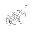
図3は、光送受信モジュール用防塵キャップ100を示す斜視図であり、図4は防塵キャップ100の上面図である。また、図5は、防塵キャップ100の正面図であり、図6は、防塵キャップ100の側面図である。
FIG. 3 is a perspective view showing a
これらの図に示すように、防塵キャップ100は、2つのコネクタ部110a,110bと、支持部140を有する。これらの部分は樹脂又はゴムにより一体形成されてよい。支持部140は光送受信モジュール300の送信用アダプタ及び受信アダプタの双方を覆う平板状の部分を有している。コネクタ部110a,110bのうちの一方は光送受信モジュール300の送信用アダプタに圧入され、他方は光送受信モジュール300の受信用アダプタに圧入される。このため、コネクタ部110a,110bの外形状は光ファイバーケーブルのコネクタとほぼ同様、一方向に延伸し、その断面形状は送信用アダプタ及び受信アダプタの内形状に適合するものとなっている。支持部140の平板状の部分の表面には、コネクタ部110a,110bが左右に並ぶように立設されており、その裏面にはつまみ部140aが設けられている。このつまみ部140aを掴むことにより、防塵キャップ100の光送受信モジュール300への脱着を容易に行うことができる。なお、以下では、コネクタ部110aが送信用アダプタに圧入され、コネクタ部110bが受信用アダプタに圧入されるものとする。
As shown in these figures, the
コネクタ部110a,110bの先端には開口111a,111bが設けられており、その内部には光伝送路130の両端部が配置されている。図4及び図6に示すように、防塵キャップ100には光伝送路130が内蔵されており、コネクタ部110aの開口111aに入射した光は、伝送路130を通って、コネクタ部110bの開口111bから出射される。具体的には、コネクタ部110aの開口111aは円形をなしており、コネクタ部110aにはコネクタ部110aの延伸方向に沿って伸びる円筒状の内部空間が形成されている。この内部空間にはコネクタ部110aの延伸方向に沿って延伸する細長い円筒状の光伝送路支持部120aが配置されている。光伝送路支持部120はコネクタ部110aと一体的に形成されている。光伝送路支持部120aはコネクタ部110aの内部空間の底に立設されており、その中心には光伝送路130が挿通され、光伝送路支持部120aの先端には光伝送路130の一端が露呈している。光伝送路130は、例えばガラスやプラスチックにより形成された光ファイバである。
同様に、コネクタ部110bの開口111bも円形をなしており、コネクタ部110bにはコネクタ部110bの延伸方向に沿って伸びる円筒状の内部空間が形成されている。この内部空間にはコネクタ部110bの延伸方向に沿って延伸する細長い円筒状の光伝送路支持部120bが配置されている。光伝送路支持部120bはコネクタ部110bと一体的に形成されている。光伝送路支持部120bはコネクタ部110bの内部空間の底に立設されており、その中心には光伝送路130が挿通され、光伝送路支持部120bの先端には光伝送路130の他端が露呈している。
Similarly, the opening 111b of the
光伝送路130は、コネクタ部110aの中心をその延伸方向に沿って伸びており、支持部140に進入する。支持部140において光伝送路130はコネクタ部110b側に湾曲し、そのままコネクタ部110bの中心に進入する。光伝送路130は、コネクタ部110bの中心をその延伸方向に沿って伸び、上述のように、その先端が光伝送路支持部120bの先端から露呈する。すなわち、光伝送路130は、光伝送路支持部120aの中心、コネクタ部110aの中心、支持部140、コネクタ部110bの中心、及びコネクタ部120bの中心を順に通るよう設けられている。
The
なお、光伝送路130は、伝送する光を減衰する光アッテネータを含んでよい。また、光伝送路130を意図した割合だけ光を減衰させる材料を添加物の種類やその濃度を制御し、屈折率分布を可変させることにより形成し、その全体を光アッテネータとして構成してよい。また、光伝送路130の内部全体に光を反射するミラーコーティングを施したものを含んでよい。この場合、ミラーは、コーティングする誘電体多層膜の屈折率分布を制御することでその反射率を任意で選択することにより、所期の割合だけ光信号を減衰させる光アッテネータとして機能させることができる。なお、前記光アッテネータは防塵キャップ100個々に対して任意の減衰量を設定できるが、自身の減衰量を可変させることはできない。
The
光送受信モジュール300は動作試験モードを有しており、この動作試験モードにおいては送信用アダプタからテスト光が出射される。こうして送信用アダプタから出射される光は、コネクタ部110aの開口111a内に配置された光伝送路130の端部から入射する。入射した光はコネクタ部110b側に伝送され、コネクタ部110bの開口111b内に配置された光伝送路130の端部から出射する。そして、出射した光は、受信用アダプタに入射するようになっている。光送受信モジュール300は、動作試験モードにおいて、受信用アダプタに入射される光の強度が所定の基準を満足するものか判断し、その結果をランプなどにより出力する。
The optical transmission /
なお、防塵キャップ100は、光送受信モジュール300から射出されたレーザ光を遮断する黒色ゴム等の遮光性の高い素材で構成されてよい。
The
以上説明した実施形態によれば、防塵キャップ100を取り外すことなく光送受信モジュール300の動作試験を行うことができる。光送受信モジュール300の送信用アダプタ及び受信用アダプタは防塵キャップ100によって封止されているため、塵によって動作不良品と判定されることがなくなる。また、光コネクタの清掃や送信用アダプタや受信用アダプタの内部の清掃が不要となるので、コスト削減が実現される。
According to the embodiment described above, the operation test of the optical transmission /
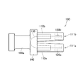
なお、本発明は上記実施形態には限定されず、種々の変形が可能である。図7は、本発明の他の実施形態に係る防塵キャップ200を示す上面図を示している。同図に示す防塵キャップ200では、光伝送部支持部120a、120bに代えて、フェルール220a,220bがそれぞれ設けられている。フェルール220a,220bはジルコニア又は金属により、コネクタ部110a,110b及び支持部140とは別体に形成されている。フェルール220a,220bは細長い円柱状をなし、中心軸にそって光伝送路130の各端部が挿通されており、各フェルール220a,220bの先端に光伝送路130の各端部が露呈している。コネクタ部110aの円筒状の内部空間の底には、その中心にフェルール220aと略同径の孔が開設されており、フェルール220aの基端側が嵌め込まれている。同様に、コネクタ部110bの円筒状の内部空間の底にも、その中心にフェルール220aと略同径の孔が開設されており、フェルール220bの基端側が嵌め込まれている。そして、送信用アダプタや受信用アダプタの側にもフェルール(不図示)が配置されており、防塵キャップ200を光送受信モジュール300に取り付けると、フェルール220a,220bは送信用アダプタや受信用アダプタのフェルールとそれぞれ対向する状態となる。なお、フェルール220a,220bは、送信用アダプタや受信用アダプタに適合するコネクタのフェルールと同じ形状であるのが好ましい。
The present invention is not limited to the above embodiment, and various modifications are possible. FIG. 7 shows a top view showing a
また、フェルール220a,220bが光送受信モジュール300側の各フェルールと接触することで、それらのフェルールの端面が傷つくのを避ける為、防塵キャップ200を光送受信モジュールに装着したときに、フェルール220a,220bの各先端と、光送受信モジュール300側の各フェルールの先端と、の間に間隙が設けられるようにしてよい。
Further, in order to prevent the end faces of the ferrules from being damaged by contacting the
100,200 防塵キャップ、110a,110b コネクタ部、120a,120b 光伝送路支持部、130 光伝送路、140 支持部、140a つまみ部、220a,220b フェルール、300 光送受信モジュール、400 光伝送装置。 100, 200 dustproof cap, 110a, 110b connector part, 120a, 120b optical transmission line support part, 130 optical transmission line, 140 support part, 140a knob part, 220a, 220b ferrule, 300 optical transmission / reception module, 400 optical transmission device.
Claims (7)
前記送信用アダプタと隣り合うよう前記光送受信モジュールに設けられた受信用アダプタに圧入され、先端に開口を有する受信側コネクタ部と、
前記送信側コネクタ部及び前記受信側コネクタ部の基端側に一体的に設けられ、前記送信側コネクタ部及び前記受信側コネクタ部を支持する支持部と、
前記送信側コネクタ部、前記支持部及び前記受信側コネクタ部の内部を順に通るよう設けられ、前記送信側コネクタ部の前記開口から入射する光を前記受信側コネクタ部の前記開口まで伝送する光伝送路と、を含む防塵キャップであって、
当該防塵キャップが前記光送受信モジュールに圧入されるとき、前記送信側コネクタ部の断面は、前記送信用アダプタの内側形状に適合し、かつ、前記受信側コネクタ部の断面は、前記受信用アダプタの内側形状に適合し、
前記送信側コネクタ部の断面外形は、前記送信側コネクタ部の遠端から前記支持部へ向かって増大し、
前記受信側コネクタ部の断面外形は、前記受信側コネクタ部の遠端から前記支持部へ向かって増大し、
前記送信側コネクタ部及び前記受信側コネクタ部は、前記送信側コネクタ部の前記先端及び前記受信側コネクタ部の前記先端に近いほど離れる、相互に対向する面を有し、
前記光伝送路の一の端部は、前記送信側コネクタ部の開口内部に設けられ、
前記光伝送路の他の端部は、前記受信側コネクタ部の開口内部に設けられる、
防塵キャップ。 A transmitter connector that is press-fitted into the transmitter adapter provided in the optical transmitter / receiver module and has an opening at the tip.
A receiving side connector portion that is press-fitted into a receiving adapter provided in the optical transmission / reception module so as to be adjacent to the transmitting adapter and has an opening at the tip, and a receiving side connector portion.
A support portion that is integrally provided on the base end side of the transmitting side connector portion and the receiving side connector portion and supports the transmitting side connector portion and the receiving side connector portion, and a support portion.
Optical transmission provided so as to pass through the inside of the transmitting side connector portion, the supporting portion, and the receiving side connector portion in order, and transmitting light incident from the opening of the transmitting side connector portion to the opening of the receiving side connector portion. A dustproof cap that includes a road and
When the dust cap is press-fitted into the optical transmission / reception module, the cross section of the transmitting side connector portion conforms to the inner shape of the transmitting adapter, and the cross section of the receiving side connector portion is the cross section of the receiving adapter. Fits the inner shape,
Cross-sectional profile of the transmission side connector section increases towards the distal end of the transmitting-side connector unit to the support unit,
Cross-sectional profile of the receiving-side connector portion, increases towards the support from the far end of the receiving-side connector portion,
The transmitting side connector portion and the receiving side connector portion have surfaces facing each other, which are closer to the tip of the transmitting side connector portion and the tip of the receiving side connector portion.
One end of the optical transmission line is provided inside the opening of the transmission side connector portion .
The other end of the optical transmission line is provided inside the opening of the receiving side connector .
Dustproof cap.
前記送信側コネクタ部と前記受信側コネクタ部と前記支持部は黒色ゴムにより形成される、防塵キャップ。 The dustproof cap according to claim 1.
A dustproof cap in which the transmitting side connector portion, the receiving side connector portion, and the supporting portion are formed of black rubber.
前記送信側コネクタ部と前記受信側コネクタ部はそれぞれフェルールを有する、防塵キャップ。 The dustproof cap according to claim 1 or 2.
A dustproof cap in which the transmitting side connector portion and the receiving side connector portion each have a ferrule.
前記送信側コネクタ部と前記受信側コネクタ部のフェルールは、前記防塵キャップの前記光送受信モジュールへの取り付け状態において、それぞれその先端が、光送受信モジュール側のフェルールの先端と離間するよう設けられる、防塵キャップ。 The dustproof cap according to claim 3.
The ferrules of the transmitting side connector portion and the receiving side connector portion are provided so that their tips are separated from the tips of the ferrules on the optical transmitting / receiving module side when the dustproof cap is attached to the optical transmitting / receiving module. cap.
前記光伝送路は、ガラス又はプラスチックで作られた光ファイバである、防塵キャップ。 The dustproof cap according to claim 1 or 2.
The optical transmission line is a dustproof cap which is an optical fiber made of glass or plastic.
前記防塵キャップは、
前記送信用アダプタに圧入され、先端に開口を有する送信側コネクタ部と、
前記受信用アダプタに圧入され、先端に開口を有する受信側コネクタ部と、
前記送信側コネクタ部及び前記受信側コネクタ部の基端側に一体的に設けられ、前記送信側コネクタ部及び前記受信側コネクタ部を支持する支持部と、
前記送信側コネクタ部、前記支持部及び前記受信側コネクタ部の内部を順に通るよう設けられ、前記送信側コネクタ部の前記開口から入射する光を前記受信側コネクタ部の前記開口まで伝送する光伝送路と、
を含み、
当該防塵キャップが前記光送受信モジュールに圧入されるとき、前記送信側コネクタ部の断面は、前記送信用アダプタの内側形状に適合し、かつ、前記受信側コネクタ部の断面は、前記受信用アダプタの内側形状に適合し、
前記送信側コネクタ部の断面外形は、前記送信側コネクタ部の遠端から前記支持部へ向かって増大し、
前記受信側コネクタ部の断面外形は、前記受信側コネクタ部の遠端から前記支持部へ向かって増大し、
前記送信側コネクタ部及び前記受信側コネクタ部は、前記送信側コネクタ部の前記先端及び前記受信側コネクタ部の前記先端に近いほど離れる、相互に対向する面を有し、
前記光伝送路の一の端部は、前記送信側コネクタ部の開口内部に設けられ、
前記光伝送路の他の端部は、前記受信側コネクタ部の開口内部に設けられる、
光送受信モジュール。 An optical transmission / reception module having a transmission adapter and a reception adapter provided adjacent to each other, and a dustproof cap attached to the transmission adapter and the reception adapter.
The dust cap is
A transmission-side connector that is press-fitted into the transmission adapter and has an opening at the tip,
A receiving-side connector that is press-fitted into the receiving adapter and has an opening at the tip,
A support portion that is integrally provided on the base end side of the transmitting side connector portion and the receiving side connector portion and supports the transmitting side connector portion and the receiving side connector portion, and a support portion.
Optical transmission provided so as to pass through the inside of the transmitting side connector portion, the supporting portion, and the receiving side connector portion in order, and transmitting light incident from the opening of the transmitting side connector portion to the opening of the receiving side connector portion. Road and
Including
When the dust cap is press-fitted into the optical transmission / reception module, the cross section of the transmitting side connector portion conforms to the inner shape of the transmitting adapter, and the cross section of the receiving side connector portion is the cross section of the receiving adapter. Fits the inner shape,
Cross-sectional profile of the transmission side connector section increases towards the distal end of the transmitting-side connector unit to the support unit,
Cross-sectional profile of the receiving-side connector portion, increases towards the support from the far end of the receiving-side connector portion,
The transmitting side connector portion and the receiving side connector portion have surfaces facing each other, which are closer to the tip of the transmitting side connector portion and the tip of the receiving side connector portion.
One end of the optical transmission line is provided inside the opening of the transmission side connector portion .
The other end of the optical transmission line is provided inside the opening of the receiving side connector .
Optical transmitter / receiver module.
前記光伝送路は、ガラス又はプラスチックで作られた光ファイバである、防塵キャップ。 The optical transmission / reception module according to claim 6.
The optical transmission line is a dustproof cap which is an optical fiber made of glass or plastic.
Priority Applications (3)
| Application Number | Priority Date | Filing Date | Title |
|---|---|---|---|
| JP2016076140A JP6809804B2 (en) | 2016-04-05 | 2016-04-05 | Dustproof cap for optical transmission / reception module and optical transmission / reception module equipped with it |
| US15/471,441 US9977193B2 (en) | 2016-04-05 | 2017-03-28 | Dust cap and optical transceiver |
| CN201710213011.1A CN107272123B (en) | 2016-04-05 | 2017-04-01 | Dust cover for optical transceiver module and optical transceiver module provided with same |
Applications Claiming Priority (1)
| Application Number | Priority Date | Filing Date | Title |
|---|---|---|---|
| JP2016076140A JP6809804B2 (en) | 2016-04-05 | 2016-04-05 | Dustproof cap for optical transmission / reception module and optical transmission / reception module equipped with it |
Publications (3)
| Publication Number | Publication Date |
|---|---|
| JP2017187612A JP2017187612A (en) | 2017-10-12 |
| JP2017187612A5 JP2017187612A5 (en) | 2019-03-07 |
| JP6809804B2 true JP6809804B2 (en) | 2021-01-06 |
Family
ID=59958697
Family Applications (1)
| Application Number | Title | Priority Date | Filing Date |
|---|---|---|---|
| JP2016076140A Active JP6809804B2 (en) | 2016-04-05 | 2016-04-05 | Dustproof cap for optical transmission / reception module and optical transmission / reception module equipped with it |
Country Status (3)
| Country | Link |
|---|---|
| US (1) | US9977193B2 (en) |
| JP (1) | JP6809804B2 (en) |
| CN (1) | CN107272123B (en) |
Families Citing this family (7)
| Publication number | Priority date | Publication date | Assignee | Title |
|---|---|---|---|---|
| USD938366S1 (en) * | 2017-11-25 | 2021-12-14 | Jack William Smith | Dust cap flange for fiber optic adapters |
| WO2019104273A1 (en) * | 2017-11-25 | 2019-05-31 | Smith Jack William | Dust and port idetification cap for fiber optic adapters |
| US10761281B1 (en) | 2019-05-31 | 2020-09-01 | Cisco Technology, Inc. | Optical module plug for open optical module port |
| US11536921B2 (en) * | 2020-02-11 | 2022-12-27 | Corning Research & Development Corporation | Fiber optic terminals having one or more loopback assemblies |
| US11526143B2 (en) | 2020-05-27 | 2022-12-13 | Cisco Technology, Inc. | Method and apparatus for protection of network device during increase in environmental contamination |
| JP1694347S (en) * | 2021-02-25 | 2021-09-06 | ||
| USD969091S1 (en) * | 2021-04-30 | 2022-11-08 | Japan Aviation Electronics Industry, Limited | Cap for connector |
Family Cites Families (13)
| Publication number | Priority date | Publication date | Assignee | Title |
|---|---|---|---|---|
| US4736100A (en) * | 1986-07-31 | 1988-04-05 | Amp Incorporated | Optical loop attenuator simulating an optical system |
| US20010028771A1 (en) * | 2000-03-02 | 2001-10-11 | Claes Johansson | Protective cover for an optical transceiver |
| US6439776B1 (en) * | 2000-05-15 | 2002-08-27 | Joseph C. Harrison | Fiber optic loop support |
| US6398422B1 (en) * | 2000-07-12 | 2002-06-04 | Molex Incorporated | Dual-function dust cover |
| US6599033B1 (en) * | 2000-10-30 | 2003-07-29 | Infineon Technologies Ag | Device for sealing a coupling unit for an optoelectronic component against contaminants |
| US20030063862A1 (en) * | 2001-10-01 | 2003-04-03 | Woodhead Industries, Inc. | Holder for optical loopback assembly with release mechanism |
| US6985668B2 (en) * | 2003-07-15 | 2006-01-10 | National Semiconductor Corporation | Multi-purpose optical light pipe |
| US7945139B2 (en) * | 2007-06-13 | 2011-05-17 | Corning Cable Systems Llc | Dust cap for fiber optic adapter |
| GB2463332B (en) * | 2009-02-26 | 2011-05-25 | Advanced Fiber Products Ltd | Fibre optic connector assembly |
| US8224146B2 (en) * | 2010-02-05 | 2012-07-17 | Panduit Corp. | Block-out device for fiber optic adapter |
| WO2013020029A2 (en) * | 2011-08-04 | 2013-02-07 | Neitge Dan J | Dust cap for fiber optic cable or adapter |
| CN203054267U (en) * | 2012-12-14 | 2013-07-10 | 泰科电子(上海)有限公司 | Dustproof apparatus and connector assembly |
| US9709755B2 (en) * | 2015-01-26 | 2017-07-18 | Westek Electronics, Inc. | Multi-tool for fiber optic applications |
-
2016
- 2016-04-05 JP JP2016076140A patent/JP6809804B2/en active Active
-
2017
- 2017-03-28 US US15/471,441 patent/US9977193B2/en active Active
- 2017-04-01 CN CN201710213011.1A patent/CN107272123B/en active Active
Also Published As
| Publication number | Publication date |
|---|---|
| US20170285273A1 (en) | 2017-10-05 |
| CN107272123A (en) | 2017-10-20 |
| JP2017187612A (en) | 2017-10-12 |
| CN107272123B (en) | 2020-01-07 |
| US9977193B2 (en) | 2018-05-22 |
Similar Documents
| Publication | Publication Date | Title |
|---|---|---|
| JP6809804B2 (en) | Dustproof cap for optical transmission / reception module and optical transmission / reception module equipped with it | |
| US10200118B2 (en) | Multimode launch systems for use in performing an OTDR measurement on a multi-fiber array DUT and method of performing same | |
| US8705931B2 (en) | Dust cap assembly for sealing an optical fiber ferrule and related methods | |
| US7680384B2 (en) | Installation tool with integrated visual fault indicator for field-installable mechanical splice connector | |
| US10444439B2 (en) | Optical connector and optical coupling structure | |
| US7665901B2 (en) | Protective fiber optic union adapters | |
| JP2008535037A (en) | Ferrule having multi-fiber MT type connector, V-groove lens array, and manufacturing method | |
| JP2003066291A (en) | Optical connector | |
| JP2002181695A (en) | Leak sensor | |
| US20210373250A1 (en) | Dust cap for fiber optic adapters | |
| KR102243081B1 (en) | Apparatus and Method for Detecting Defects in Ferrule for Optical Connector | |
| WO2013191268A1 (en) | Optical connector | |
| JP2004109949A (en) | Plug of optical fiber connecter and optical fiber wiring board | |
| JP2018031998A (en) | Adaptor and optical connection structure | |
| JP2006349869A (en) | End face cover of optical connector, optical connector terminating device, and device for discriminating end face quality of optical connector | |
| JP2020095182A (en) | Optical connector ferrule and optical connector | |
| JP2005208389A (en) | Optical fiber connecting structure | |
| Clement et al. | Connector/Module Interface | |
| JP2010282130A (en) | Mechanism for holding fiber stub |
Legal Events
| Date | Code | Title | Description |
|---|---|---|---|
| A521 | Request for written amendment filed |
Free format text: JAPANESE INTERMEDIATE CODE: A523 Effective date: 20190121 |
|
| A621 | Written request for application examination |
Free format text: JAPANESE INTERMEDIATE CODE: A621 Effective date: 20190121 |
|
| A977 | Report on retrieval |
Free format text: JAPANESE INTERMEDIATE CODE: A971007 Effective date: 20191212 |
|
| A131 | Notification of reasons for refusal |
Free format text: JAPANESE INTERMEDIATE CODE: A131 Effective date: 20200107 |
|
| A521 | Request for written amendment filed |
Free format text: JAPANESE INTERMEDIATE CODE: A523 Effective date: 20200304 |
|
| A02 | Decision of refusal |
Free format text: JAPANESE INTERMEDIATE CODE: A02 Effective date: 20200407 |
|
| A521 | Request for written amendment filed |
Free format text: JAPANESE INTERMEDIATE CODE: A523 Effective date: 20200702 |
|
| C60 | Trial request (containing other claim documents, opposition documents) |
Free format text: JAPANESE INTERMEDIATE CODE: C60 Effective date: 20200702 |
|
| A911 | Transfer to examiner for re-examination before appeal (zenchi) |
Free format text: JAPANESE INTERMEDIATE CODE: A911 Effective date: 20200714 |
|
| C21 | Notice of transfer of a case for reconsideration by examiners before appeal proceedings |
Free format text: JAPANESE INTERMEDIATE CODE: C21 Effective date: 20200721 |
|
| A131 | Notification of reasons for refusal |
Free format text: JAPANESE INTERMEDIATE CODE: A131 Effective date: 20200923 |
|
| A521 | Request for written amendment filed |
Free format text: JAPANESE INTERMEDIATE CODE: A523 Effective date: 20200928 |
|
| TRDD | Decision of grant or rejection written | ||
| A01 | Written decision to grant a patent or to grant a registration (utility model) |
Free format text: JAPANESE INTERMEDIATE CODE: A01 Effective date: 20201124 |
|
| A61 | First payment of annual fees (during grant procedure) |
Free format text: JAPANESE INTERMEDIATE CODE: A61 Effective date: 20201210 |
|
| R150 | Certificate of patent or registration of utility model |
Ref document number: 6809804 Country of ref document: JP Free format text: JAPANESE INTERMEDIATE CODE: R150 |
|
| R250 | Receipt of annual fees |
Free format text: JAPANESE INTERMEDIATE CODE: R250 |