JP6807112B2 - How to set print conditions and print system - Google Patents
How to set print conditions and print system Download PDFInfo
- Publication number
- JP6807112B2 JP6807112B2 JP2019079041A JP2019079041A JP6807112B2 JP 6807112 B2 JP6807112 B2 JP 6807112B2 JP 2019079041 A JP2019079041 A JP 2019079041A JP 2019079041 A JP2019079041 A JP 2019079041A JP 6807112 B2 JP6807112 B2 JP 6807112B2
- Authority
- JP
- Japan
- Prior art keywords
- image
- data
- printing
- conveyor
- Prior art date
- Legal status (The legal status is an assumption and is not a legal conclusion. Google has not performed a legal analysis and makes no representation as to the accuracy of the status listed.)
- Active
Links
- 238000007639 printing Methods 0.000 claims description 116
- 238000000034 method Methods 0.000 claims description 40
- GNFTZDOKVXKIBK-UHFFFAOYSA-N 3-(2-methoxyethoxy)benzohydrazide Chemical compound COCCOC1=CC=CC(C(=O)NN)=C1 GNFTZDOKVXKIBK-UHFFFAOYSA-N 0.000 claims description 2
- 238000003860 storage Methods 0.000 description 29
- 238000004891 communication Methods 0.000 description 14
- 230000006870 function Effects 0.000 description 14
- 238000000605 extraction Methods 0.000 description 12
- 239000003550 marker Substances 0.000 description 12
- 230000015654 memory Effects 0.000 description 12
- 239000000284 extract Substances 0.000 description 6
- 230000007274 generation of a signal involved in cell-cell signaling Effects 0.000 description 6
- 238000012546 transfer Methods 0.000 description 6
- 238000004519 manufacturing process Methods 0.000 description 3
- 238000012545 processing Methods 0.000 description 3
- 238000004364 calculation method Methods 0.000 description 2
- 238000010586 diagram Methods 0.000 description 2
- 238000005516 engineering process Methods 0.000 description 2
- 239000004973 liquid crystal related substance Substances 0.000 description 2
- 238000012856 packing Methods 0.000 description 2
- 238000002360 preparation method Methods 0.000 description 2
- 238000011144 upstream manufacturing Methods 0.000 description 2
- 230000003936 working memory Effects 0.000 description 2
- 238000006243 chemical reaction Methods 0.000 description 1
- 238000011437 continuous method Methods 0.000 description 1
- 238000013144 data compression Methods 0.000 description 1
- 238000009826 distribution Methods 0.000 description 1
- 230000006386 memory function Effects 0.000 description 1
- 238000004806 packaging method and process Methods 0.000 description 1
- 238000012360 testing method Methods 0.000 description 1
Images


Classifications
-
- B—PERFORMING OPERATIONS; TRANSPORTING
- B41—PRINTING; LINING MACHINES; TYPEWRITERS; STAMPS
- B41J—TYPEWRITERS; SELECTIVE PRINTING MECHANISMS, i.e. MECHANISMS PRINTING OTHERWISE THAN FROM A FORME; CORRECTION OF TYPOGRAPHICAL ERRORS
- B41J2203/00—Embodiments of or processes related to the control of the printing process
- B41J2203/01—Inspecting a printed medium or a medium to be printed using a sensing device
Description
本発明は、コンベアで搬送される商品や梱包容器の側面に、インクジェットプリンタを用いて印字を行う際の印字条件の設定方法、およびその設定方法を採用した印字システムに関する。 The present invention relates to a method for setting printing conditions when printing is performed using an inkjet printer on the side surface of a product or a packing container transported by a conveyor, and a printing system that employs the setting method.
商品の製造年月日、製造ロット、使用期限(賞味期限、消費期限)等を管理するため、製造ラインや物流ラインにおいて、それらの情報を商品に直接、または梱包した容器に印字している。 In order to manage the manufacturing date, manufacturing lot, expiration date (expiration date, expiry date), etc. of the product, the information is printed directly on the product or on the packaged container on the manufacturing line or distribution line.
そして近年では、日付やロット番号のように刻一刻と変化してく文字等を印字するのに最適なことから、印刷手段としてインクジェットプリンタ(以降「IJP」と略す)が用いられている(特許文献1参照)。 In recent years, an inkjet printer (hereinafter abbreviated as "IJP") has been used as a printing means because it is most suitable for printing characters that change from moment to moment, such as dates and lot numbers (Patent Documents). 1).
特許文献1記載の印字システムでは、IJPは静止しており、印字対象物(商品、梱包容器、以降、「ワーク」という)がコンベア上を移動している。ワークの側面の狙った位置に狙い通りの内容を印字するためには、コンベアの搬送速度、印字する位置、印字の濃度等を設定する必要がある。一般に、このような印字の際に必要となる内容を「印字条件」と呼んでいる。
In the printing system described in
現状では、印字条件のうち位置については、ユーザが印字面の端から印字する位置までの距離を計測し、その値をIJPのコントローラに入力している。また搬送速度については、タコメータ等を用いて直接コンベアの速度を測定し、その値をコントローラに入力している。 At present, as for the position among the printing conditions, the user measures the distance from the edge of the printing surface to the printing position and inputs the value to the IJP controller. As for the transport speed, the speed of the conveyor is directly measured using a tachometer or the like, and the value is input to the controller.
そして、コントローラに入力した印字条件で試しに印字を行い、狙った通りの印字が行われるか否か確認しながら、印字条件を設定している。 Then, printing is performed on a trial basis under the printing conditions input to the controller, and the printing conditions are set while confirming whether or not printing is performed as intended.
しかし、上述した印字条件の設定方法では、印字条件を決定するまでに時間がかかり、またワークに不要な印字を行う必要がある。そのため、仮想現実(AR:Augmented Reality)の技術を利用して、試し印字を省略する方法が提案されている。 However, in the above-described printing condition setting method, it takes time to determine the printing conditions, and it is necessary to perform unnecessary printing on the workpiece. Therefore, a method of omitting the test printing by using the technology of virtual reality (AR) has been proposed.
特許文献2に記載の印字システムは、ハンドヘルド型のIJPを用いる点で本発明とは異なっているが、携帯端末のディスプレイに映し出された印字媒体にAR技術を用いて印字イメージを表示している。そして、そのディスプレイの画面上で印字の大きさや位置を調節して、印字条件を設定している。
The printing system described in
特許文献2に記載の印字システムを採用すれば、試し印字を行うことなく印字条件を設定でき、しかも条件の設定に要する時間を大幅に短縮できる。
If the printing system described in
これに対し、コンベアで搬送されるワークの側面に印字を行う場合には、コンベアの搬送速度に合わせて印字のタイミングを調節する必要がある。 On the other hand, when printing is performed on the side surface of the work transported by the conveyor, it is necessary to adjust the printing timing according to the transport speed of the conveyor.
印字のタイミングを調節する方法として、コンベアに取り付けられたエンコーダとIJPを接続することによって、コンベアの位置情報を自動的に取得する方法もあるが、エンコーダが取り付けられていないコンベアには適用できない。そのような場合、事前に、タコメータ等を用いてコンベアの搬送速度を計測し、その値をIJPのコントローラに手動で入力している。 As a method of adjusting the printing timing, there is a method of automatically acquiring the position information of the conveyor by connecting the encoder attached to the conveyor and the IJP, but this is not applicable to the conveyor without the encoder attached. In such a case, the conveyor speed is measured in advance using a tachometer or the like, and the value is manually input to the IJP controller.
本発明は、このような状況に鑑みてなされたもので、ARを利用した編集作業の流れの中で、エンコーダやタコメータ等を用いることなくコンベアの搬送速度を取得できる方法を提供することを目的とする。 The present invention has been made in view of such a situation, and an object of the present invention is to provide a method capable of acquiring a conveyor transfer speed without using an encoder, a tachometer, or the like in the flow of editing work using AR. And.
上記目的を達成するため、本発明に係る印字条件の設定方法は、コンベアによって搬送されるワークの側面にインクジェットプリンタを用いて印字を行う際の印字条件を設定する方法であって、以下のa〜hのステップを含むことを特徴とする。
a)携帯端末のカメラによって、前記コンベアで搬送されるワークを、当該コンベアの近傍に設置された前記インクジェットプリンタの印字ヘッドと共に撮影する。
b)撮影された動画を構成する複数の画像から、前記ワークの印字面が映った画像を取り出すと共に、当該画像から印字面の画像を抽出する。
c)前記画像から印字ヘッドの近傍に設置された一対のマーカの画像を抽出する。
d)前記抽出した一対のマーカ間の距離を、予め用意した実際のマーカ間の距離と比較することによって前記印字面の寸法を算出する。
e)前記動画を構成する複数の画像から前記印字面の一辺が前記一対のマーカのそれぞれを通過するときの時刻データを取り出し、当該時刻データの差で前記マーカ間の距離を割ることによって前記コンベアの搬送速度を算出する。
f)前記抽出された印字面の画像を前記携帯端末のディスプレイに表示すると共に、印字データに基づいて作成された仮想の印字イメージを、前記印字面に重ねて表示する。
g)前記ディスプレイに表示された印字面に対して前記印字イメージの位置を調節する。
h)前記印字面に対する印字イメージの位置が確定した画像データから、前記ワークの実際の印字面の印字位置を特定するデータを読み出す。
In order to achieve the above object, the printing condition setting method according to the present invention is a method of setting the printing condition when printing is performed using an inkjet printer on the side surface of the work conveyed by the conveyor, and the following a It is characterized by including steps of ~ h.
a) The camera of the mobile terminal takes a picture of the work conveyed by the conveyor together with the print head of the inkjet printer installed near the conveyor.
b) An image showing the print surface of the work is extracted from a plurality of images constituting the captured moving image, and an image of the print surface is extracted from the image.
c) An image of a pair of markers installed in the vicinity of the print head is extracted from the image.
d) The dimensions of the printed surface are calculated by comparing the distance between the pair of extracted markers with the actual distance between the markers prepared in advance.
e) The conveyor is obtained by extracting time data when one side of the printed surface passes through each of the pair of markers from a plurality of images constituting the moving image and dividing the distance between the markers by the difference between the time data. Calculate the transport speed of.
f) The image of the extracted print surface is displayed on the display of the mobile terminal, and the virtual print image created based on the print data is displayed superimposed on the print surface.
g) The position of the print image is adjusted with respect to the print surface displayed on the display.
h) From the image data in which the position of the print image with respect to the print surface is determined, the data for specifying the print position of the actual print surface of the work is read out.
ここで、前記印字位置を特定するデータおよび前記コンベアの搬送速度のデータは、印字条件として、前記印字データと共に前記インクジェットプリンタのコントローラに送信されることが好ましい。 Here, it is preferable that the data for specifying the print position and the data for the transfer speed of the conveyor are transmitted to the controller of the inkjet printer together with the print data as printing conditions.
また前記gのステップにおいて、前記印字イメージの位置と共に大きさを調節し、前記hのステップにおいて、前記印字面に対する印字イメージの位置および大きさが確定した画像データから、前記ワークの印字面の印字位置および大きさを特定するデータを読み出すことが好ましい。 Further, in the step g, the size is adjusted together with the position of the print image, and in the step h, the print surface of the work is printed from the image data in which the position and size of the print image with respect to the print surface are determined. It is preferable to read the data that specifies the position and size.
前記b〜hのステップは、前記携帯端末にインストールされたアプリケーションソフトを用いて実行されることが好ましい。 The steps b to h are preferably executed using the application software installed on the mobile terminal.
前記一対のマーカは、前記印字ヘッドの筐体の背面に、水平方向の高さが略等しくなるように取り付けられることが好ましい。 It is preferable that the pair of markers are attached to the back surface of the housing of the print head so that the heights in the horizontal direction are substantially equal.
前記印字ヘッドとして、複数のノズルが鉛直方向に等間隔に配置されたドロップオンデマンド方式の印字ヘッドを用いることが好ましい。 As the print head, it is preferable to use a drop-on-demand type print head in which a plurality of nozzles are arranged at equal intervals in the vertical direction.
また本発明に係る印字システムは、コンベアによって搬送されるワークの側面にインクジェットプリンタを用いて印字を行う印字システムであって、
ユーザによって操作され、前記インクジェットプリンタの印字条件を設定する携帯端末と、
記コンベアの近傍に設置され、前記ワークの側面に印字を行う印字ヘッド、および前記携帯端末から送信された印字データおよび印字条件のデータを受信し、前記印字ヘッドの駆動信号およびタイミング信号を生成するコントローラを具備したインクジェットプリンタと、を備え、
前記携帯端末は、
内蔵のカメラによって、前記コンベア搬送されるワークを、当該コンベアの近傍に設置された前記インクジェットプリンタの印字ヘッドと共に撮影し、
撮影された動画を構成する複数の画像から、前記ワークの印字面が映った画像を取り出すと共に、当該画像から印字面の画像を抽出し、
前記画像から印字ヘッドの近傍に設置された一対のマーカの画像を抽出し、
前記抽出した一対のマーカ間の距離を、予め用意した実際のマーカ間の距離と比較することによって前記印字面の寸法を算出し、
前記動画を構成する複数の画像から前記印字面の一辺が前記一対のマーカのそれぞれを通過するときの時刻データを取り出し、当該時刻データの差で前記マーカ間の距離を割ることによって前記コンベアの搬送速度を算出し、
前記抽出された印字面の画像を前記携帯端末のディスプレイに表示すると共に、印字データに基づいて作成された仮想の印字イメージを、前記印字面に重ねて表示し、
前記ディスプレイに表示された印字面に対して前記印字イメージの位置を調節し、
前記印字面に対する印字イメージの位置が確定した画像データから、前記ワークの印字面の印字位置を特定するデータを取り出すことを特徴とする。
Further, the printing system according to the present invention is a printing system that prints on the side surface of a work conveyed by a conveyor using an inkjet printer.
A mobile terminal operated by a user to set printing conditions for the inkjet printer, and
A print head that is installed near the conveyor and prints on the side surface of the work, receives print data and print condition data transmitted from the mobile terminal, and generates a drive signal and a timing signal of the print head. With an inkjet printer equipped with a controller,
The mobile terminal
With the built-in camera, the work transported on the conveyor is photographed together with the print head of the inkjet printer installed in the vicinity of the conveyor.
An image showing the print surface of the work is extracted from a plurality of images constituting the captured moving image, and an image of the print surface is extracted from the image.
An image of a pair of markers installed near the print head is extracted from the image, and the image is extracted.
The dimensions of the printed surface are calculated by comparing the distance between the pair of extracted markers with the actual distance between the markers prepared in advance.
Time data when one side of the printing surface passes through each of the pair of markers is taken out from a plurality of images constituting the moving image, and the distance between the markers is divided by the difference between the time data to convey the conveyor. Calculate the speed,
The extracted image of the printed surface is displayed on the display of the mobile terminal, and the virtual print image created based on the print data is displayed on the printed surface.
Adjust the position of the print image with respect to the print surface displayed on the display.
It is characterized in that data for specifying the print position of the print surface of the work is extracted from the image data in which the position of the print image with respect to the print surface is fixed.
本発明の印字条件の設定方法によれば、印字ヘッドの近傍に設置された一対のマーカを含む動画を撮影することで、コンベアの搬送速度を簡単に算出することができる。結果として、ARを利用した編集作業の一連の流れの中で、コンベアの搬送速度を含む全ての印字条件を簡単に設定することができ、しかも印字条件の設定に要する時間を大幅に短縮できる。 According to the printing condition setting method of the present invention, the conveyor speed can be easily calculated by shooting a moving image including a pair of markers installed near the print head. As a result, all printing conditions including the conveyor transfer speed can be easily set in a series of editing work using AR, and the time required for setting the printing conditions can be significantly shortened.
以下、本発明の実施の形態に係る印字条件の設定方法および印字システムについて、図面を参照して説明する。 Hereinafter, a method for setting printing conditions and a printing system according to an embodiment of the present invention will be described with reference to the drawings.
<印字条件の設定の手順>
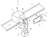
最初に、図1、図2および図3を参照して、本発明に係る印字条件の設定方法における処理手順の概要を説明する。図1に、印字条件を設定する印字システム1の概略構成を示す。図2に、携帯端末4のカメラで撮影したワーク(商品または包装箱)3とIJP5の印字ヘッド55を示す。また図3に、ワーク3の印字面31にARを用いて仮想の印字イメージPIを表示した状態を示す。
<Procedure for setting print conditions>
First, with reference to FIGS. 1, 2 and 3, the outline of the processing procedure in the printing condition setting method according to the present invention will be described. FIG. 1 shows a schematic configuration of a
本発明は、コンベア2で搬送されるワーク3の側面(印字面)31に、コンベア2に隣接して設置されたIJP5を用いて印字を行う際の印字条件の設定方法を提供するものである。
The present invention provides a method for setting printing conditions when printing is performed using the
本実施の形態では、インクを吐出するノズルが鉛直方向に複数、等間隔に配置されたドロップオンデマンド方式の印字ヘッドを用いてワークに印字を行うものとする。ただし、本発明に係る印字条件の設定方法は、コンティニュアス方式等の他の方式のインクジェットプリンタを用いて印字を行う場合にも適用できる。 In the present embodiment, it is assumed that printing is performed on the work by using a drop-on-demand type print head in which a plurality of nozzles for ejecting ink are arranged at equal intervals in the vertical direction. However, the method for setting printing conditions according to the present invention can also be applied to printing using an inkjet printer of another method such as a continuous method.
前述したように、コンベア2で搬送されるワーク3の印字面31に印字を行う場合、予め印字条件を設定する必要がある。具体的には、第1の条件として、印字面に対する印字の位置と大きさを設定する必要がある。すなわち、印字面31のどの位置に、どの大きさで印字するかを決定する必要がある。
As described above, when printing is performed on the
第2の条件として、コンベア2で搬送されるワーク3の側面に第1の条件に従って印字を行うためには、印字ヘッド55のノズルからインクが吐出するタイミングを、コンベア2の搬送速度にあわせて調節する必要があり、そのために搬送速度を計測する必要がある。
As a second condition, in order to print on the side surface of the
本発明では、上述した2つの印字条件を、ARを利用した編集作業の一連の流れの中で設定している。その前提として、図1に示すように、コンベア2で搬送されるワーク3とコンベア2に近接して設置されたIJP5の印字ヘッド55とを、ユーザUが携帯端末4のカメラを用いて撮影し、図2に示すようにワーク3と印字ヘッド55を含む動画データを取得している。そして、得られた動画データから、ワークの側面すなわち印字面31の全てと印字ヘッド55が映った画像を抽出している。
In the present invention, the above-mentioned two printing conditions are set in a series of editing work using AR. As a premise, as shown in FIG. 1, the user U photographs the
また本発明では、ARにおける現実世界を拡張する手段として、上述した画像から抽出される2つの標識を用いている。第1の標識は空間の特徴点を抽出したもので、コンベア2で搬送されるワーク3の側面の画像を抽出し、その側面を印字面とし、そこに仮想のオブジェクトとして印字イメージを重ねて表示している。
Further, in the present invention, two markers extracted from the above-mentioned image are used as means for expanding the real world in AR. The first sign extracts the feature points of the space, extracts the image of the side surface of the
図3に、このようにして抽出された印字面の画像31に、仮想の印字イメージPIを重ねて表示した画像を示す。そして図3の印字イメージPIに対し、携帯端末4の機能の一つであるオブジェクトを移動・拡大・縮小する機能を用いて、印字面31に対する印字イメージPIの位置と大きさを調節している。なお、印字される文字の大きさを変えられない場合には、文字の位置だけを変えるようにしてもよい。
FIG. 3 shows an image in which a virtual print image PI is superimposed and displayed on the
上述の手順により調節した印字イメージの位置と大きさに基づいて印字条件を設定するためには、印字面31のサイズをワーク3の実際の寸法に置き換える必要がある。本発明では、第2の標識を用いて印字面のサイズを実際の寸法に置き換えている。
In order to set the print conditions based on the position and size of the print image adjusted by the above procedure, it is necessary to replace the size of the
第2の標識は、特定のルールで黒と白のパターン化した図形である一対のマーカM1、M2を、印字ヘッド55の筐体の背面に取り付け、その一対のマーカM1、M2の画像を撮影画像から抽出したものである。マーカM1、M2は、ワーク3の印刷面31のサイズを算出するために用いられ、水平方向の高さが略等しくなるように取り付けられる。
The second sign is to attach a pair of markers M1 and M2, which are black and white patterned figures according to a specific rule, to the back surface of the housing of the
マーカ間の実際の寸法は予め用意され、携帯端末4のメモリに格納されている。従って、図3に示した印字面における印字の位置と大きさを決める寸法a、b、cを、マーカ間の距離に基づいて実際の寸法に置き換えれば、前述の第1の印字条件、即ち実際の印字面における印字データの位置および大きさを示すデータを算出できる。
The actual dimensions between the markers are prepared in advance and stored in the memory of the
次に、印字の第2の条件について説明する。図2において、ユーザUは、携帯端末4のカメラを操作してワーク3が実線で示す位置から二点差線で示す位置まで搬送される間の動画を撮影する。その動画から印字面の一辺(図では左辺AB)がマークM1とM2を通過するときの画像を取り出し、それぞれの画像データから時刻データを取り出す。
Next, the second condition of printing will be described. In FIG. 2, the user U operates the camera of the
前述したように、マークM1、M2間の距離は予め決まっているため、印字面31の左辺ABが2つのマーカM1、M2を通過するとき(図2の位置P1、P2)の時間差でマーカ間の距離を割れば、ワークの搬送速度すなわち第2の印字条件を算出できる。
As described above, since the distance between the marks M1 and M2 is predetermined, there is a time difference between the markers when the left side AB of the printed
このようにして算出した第1の印字条件で示す印字面の位置に、第2の印字条件に基づいてタイミング信号を生成し、その信号に基づいて印字ヘッド55のノズルからインクを吐出すれば、ワーク3の側面の所定の位置に所定の大きさの印字を行うことができる。
A timing signal is generated at the position of the print surface indicated by the first print condition calculated in this manner based on the second print condition, and ink is ejected from the nozzle of the
前述したように、従来の印字システムでは、エンコーダを用いてコンベアの位置情報を計測し、その情報をIJPに提供するか、タコメータ等を用いてコンベア2の搬送速度を計測し、その値をIJPのコントローラに手動で入力してタイミング信号を生成していた。
As described above, in the conventional printing system, the position information of the conveyor is measured by using an encoder and the information is provided to IJP, or the transfer speed of the
これに対し、本発明では、ARを利用した編集作業の一連の流れの中で、2つの標識を組み合わせて使用することにより、第1および第2の印字条件を設定している。すなわち、本発明に係る印字条件の設定方法では、コンベアにエンコーダを取り付けて位置情報を取得したり、タコメータ等でコンベアの搬送速度を計測する必要がない。 On the other hand, in the present invention, the first and second printing conditions are set by using the two markers in combination in a series of editing work using AR. That is, in the printing condition setting method according to the present invention, it is not necessary to attach an encoder to the conveyor to acquire position information or measure the conveyor speed with a tachometer or the like.
<携帯端末およびIJPの構成と機能>
次に、図4および図5を参照して、本発明に係る印字条件の設定方法を実現する携帯端末およびIJPの制御系の構成と各部の機能について説明する。
<Configuration and functions of mobile terminals and IJP>
Next, with reference to FIGS. 4 and 5, the configuration of the control system of the mobile terminal and the IJP that realizes the method for setting the printing conditions according to the present invention and the functions of each part will be described.
図4に示したように、携帯端末4は、制御部41、通信モジュール42、カメラ43、ディスプレイ44、操作部45および記憶部46を備えており、通常、スマートフォンやタブレットPC(Personal Computer)で構成される。
As shown in FIG. 4, the
制御部41は、携帯端末4の各部の動作を制御すると共に、記憶部46に記憶されたプログラムを読み出して、図示しないCPUで実行することにより、ブロック411〜416の各機能を実現する。
The
印字データ取得部411は、操作部44で受け付けた、または通信モジュール42で受信した印字データを取得し、記憶部46に格納する。印字データ取得部411で取得する印字データには、一対のマーカM1、M2間の距離等の、印字条件の算出に必要なデータも含まれる。
The print
画像取得部412は、カメラ43で撮影した動画のデータを取得すると共に、それを一時的に記憶部46に格納する。カメラで撮像された動画データは、通常、データの容量を減らすため、データ圧縮した後メモリに格納されるが、本実施の形態では、印字面抽出部413およびマーカ抽出部414において、圧縮されていない画像データに基づいて認識処理を行うため、非圧縮のフレーム毎の画像データを記憶部46に格納する。
The
ユーザUは、記憶部46に格納されたフレーム単位の画像データをディスプレイ45に表示し、操作部44を操作して画像を選択する。印字面抽出部413は、ユーザUの指示に従い、第1の画像認識ソフトを用いて画像の中からワーク3の印字面を第1の標識として抽出する。図2に示すような印字面31の画像が抽出された画像データは、一時的に記憶部46に格納される。
The user U displays the image data in frame units stored in the
マーカ抽出部414は、印字面抽出部413と同様に、ユーザUの操作によって、記憶部46から読み出されたフレームの画像に対し、第2の画像認識ソフトを用いて、画像の中から第2の標識である一対のマーカを抽出する。抽出された一対のマーカの画像データは、一時的に記憶部46に格納される。
Similar to the print
画像生成表示部415は、印字面抽出部413で抽出した印字面の画像を、携帯端末4のディスプレイ45に表示すると共に、記憶部46に格納された印字データを読み出して仮想の印字イメージPIを生成し、図3に示すように、そのイメージPIをディスプレイ45に表示された印字面31に重ねて表示する。
The image
印字条件設定部416は、マーカ抽出部414で抽出したマーカM1、M2の座標データを、マーカ間の距離の実測値と比較し、得られた係数を用いて印字面31の各辺の寸法を算出する。更に、ユーザの操作により設定された第1の印字条件であるa、b、cの値を実際の寸法に置き換える。
The print
更に印字条件設定部416は、マーカ抽出部414で取り出された時刻データに基づいてワーク3の搬送速度を算出する。
Further, the print
通信モジュール42は、印字条件設定部416で設定された第1および第2の印字条件のデータを、無線通信によってIJP5のコントローラ51に送信し、一方、IJP5の記憶部に格納された印字条件の算出に必要なデータを受信する。通信モジュール42は、無線LAN、Bleetooth(登録商標)などのモジュールによって構成される。
The
カメラ43は、CMOS等の撮像素子を備え、ワーク3や印字ヘッド55の撮影に用いられる。印字条件を設定するためには、数秒間の動画があれば済む。前述したように本実施の形態では、数秒間のフレーム毎の非圧縮の画像データが記憶部46に格納される。
The
操作部44およびディスプレイ45はタッチパネル式の液晶ディスプレイ等で構成される。操作部44は印字条件の設定に必要なデータの入力や第1の印字条件の設定等に使用され、ディスプレイ45はカメラ43で撮影した映像や印字イメージ等の表示に用いられる。
The
記憶部46は、ROM、フラッシュメモリ等の不揮発性メモリと、RAM等の揮発性メモリで構成される。不揮発性メモリには制御部41の各機能を実現するOSやプログラムが格納される。一方、揮発性メモリには、カメラで撮影した画像データや印字データ等が格納され、更に、制御部41での演算におけるワーキングメモリとしての機能を果たす。
The
次に、IJP5の構成を説明する。図5に示すように、IJP5は、コントローラ51、通信モジュール52、操作部53、ディスプレイ54、印字ヘッド55、記憶部56および光電センサ57を備えている。
Next, the configuration of IJP5 will be described. As shown in FIG. 5, the
コントローラ51は印字ヘッド55の動作を制御するもので、市販のパーソナルコンピュータと同様の機能を備えている。コントローラ51は、記憶部56に格納されたプログラムを読み出して、図示しないCPUで実行することにより、印字データ取得部511、プリンタドライバ512およびタイミング信号生成部513の各機能を実現する。
The
印字データ取得部511は、通信モジュール52や操作部53を介して外部から入力された印字データ等を取得し、記憶部56に格納する。
The print
プリンタドライバ512は、操作部53から入力された印字データがカラーで表現されている場合、印字データに対して色変換およびハーフトーニング(擬似中間調再現)等の処理を行い、印字ヘッド55の駆動信号を作成する。プリンタドライバ512で生成された駆動信号は、印字ヘッド55に送信される。
When the print data input from the
本実施の形態では、印字面に黒インクを用いて印字を行う場合を想定しているため、ハーフトーニングの処理だけを行う。インクドットによるハーフトーニングの処理については、広く知られているため、詳細な説明は省略する。 In the present embodiment, since it is assumed that printing is performed using black ink on the printing surface, only half toning processing is performed. Since the half toning process using ink dots is widely known, detailed description thereof will be omitted.
タイミング信号生成部513は、携帯端末4から送信されたコンベア2の搬送速度のデータに基づいてタイミング信号を生成し、印字ヘッド55に送信する。
The timing
通信モジュール52は、携帯端末4の通信モジュール42と同様の機能を有し、印字データ取得部511で取得した印字データを、無線通信により携帯端末4の印字データ取得部41に送信し、逆に、携帯端末4から送信された印字条件のデータを受信し、印字データ取得部511に引き渡す。
The
操作部53およびディスプレイ54はタッチパネル式の液晶ディスプレイ等で構成される。操作部53は印字に必要なデータの入力や印字位置の調節等に用いられ、ディスプレイ55はワーク3の印字面に印字されるデータの表示に用いられる。
The
印字ヘッド55は、プリンタドライバ512で生成された駆動信号およびタイミング信号生成部513で生成されたタイミング信号に従って、ノズルからインクを吐出し、ワーク3の側面に印字を行う。
The
前述したように、本実施の形態では、印字ヘッドとして、ドロップオンデマンド方式の印字ヘッドを用いている。後述する図7に、印字ヘッド55に形成されたノズル551の配列状態を示す。印字ヘッド55の前面には、複数のノズル551が鉛直方向に等間隔で形成されており、コントローラ51から供給される駆動信号およびタイミング信号に基づいて、所定のノズルから所定のタイミングでインクを吐出することにより、ワークの印字面に印字が行われる。
As described above, in the present embodiment, a drop-on-demand type print head is used as the print head. FIG. 7, which will be described later, shows the arrangement state of the
記憶部56は、ROM、フラッシュメモリ等の不揮発性メモリおよびRAM等の揮発性メモリで構成される。不揮発性メモリには、OSおよびコントローラ51の各ブロックの機能を実現するプログラム、更に印字データが格納される。一方、揮発性メモリは、プリンタドライバ512で駆動信号を生成する際およびタイミング信号生成部513でタイミング信号を生成する際にワーキングメモリとしての機能を果たす。
The
光電センサ57は、図1に示すように印字ヘッド55の上流側のコンベア2の近傍に設置され、ワーク3が光電センサ58を横切ったときに信号を発生する。光電センサ58の出力信号は、タイミング信号を生成する際のトリガー信号として利用され、この信号に基づいて印字面で印字を開始する位置が決定される。
As shown in FIG. 1, the
<印字条件設定の手順>
次に、図6〜図9のフローチャートを参照して、本実施の形態に係る印字システムにおいて、印字条件を設定する際の手順を説明する。最初に、図6および図7を参照して、印字条件設定の際の準備手順について説明する。
<Procedure for setting print conditions>
Next, in the printing system according to the present embodiment, a procedure for setting printing conditions will be described with reference to the flowcharts of FIGS. 6 to 9. First, a preparatory procedure for setting printing conditions will be described with reference to FIGS. 6 and 7.
最初に、図1に示すように、コンベア2の近傍にIJP5の印字ヘッド51を設置すると共に、印字ヘッドの上流側に光電センサ57を設置する(ステップS11)。印字ヘッド55は、フレーム50によって図示しないベースに固定されている。また印字ヘッド55とプリンタ本体58との間はインク供給用のパイプ59で接続され、プリンタ本体59に内蔵されたインクタンク(図示せず)から印字ヘッド55にインクが供給される。
First, as shown in FIG. 1, the
次に、携帯端末4に印字条件設定用のアプリケーションソフトをインストールする(ステップS12)。インストールされたアプリケーションソフトは記憶部46に格納される。アプリケーションソフトは、制御部41のブロック411〜416に示す機能を実現する。
Next, the application software for setting print conditions is installed on the mobile terminal 4 (step S12). The installed application software is stored in the
次に、ユーザは、印字データおよび印字条件の設定に必要なデータを用意し、操作部44または通信モジュール42を介して、それらのデータを携帯端末4に入力する。印字条件設定に必要なデータとして一対のマーカM1、M2に関するデータがある。図7を参照して、印字条件設定に必要なデータについて説明する。
Next, the user prepares print data and data necessary for setting print conditions, and inputs the data to the
図7は、印字ヘッド55の筐体の前面に形成されたノズル551と、筐体の背面に取り付けられた一対のマーカM1、M2との位置関係を示す。
FIG. 7 shows the positional relationship between the
一対のマーカM1とM2の間の距離W1は、前述した印字面31の寸法およびコンベア2の搬送速度を算出する際に必要なデータである。また一方のマーカM2とノズル551との間の間隔W2、マーカM1、M2と最上位のノズルとの間隔h1、マーカM1、M2と最下位のノズルとの間隔h2は印字面における印字イメージPIの位置a、b、cを設定する際に必要なデータである。
The distance W1 between the pair of markers M1 and M2 is data necessary for calculating the dimensions of the
ちなみに、前述の図3には、最上位のノズルの位置Htと最下位のノズルの位置Hbが示されている。これらの値は、印字イメージPIの位置を決める際の規準となる。 By the way, in FIG. 3 described above, the position Ht of the uppermost nozzle and the position Hb of the lowermost nozzle are shown. These values serve as criteria for determining the position of the print image PI.
印字条件を設定するためには、上述したデータ以外に、マーカの鉛直方向の高さとコンベア上に載置されたワーク3の側面の上辺および下辺の高さデータが必要であり、これらのデータは、予め計測され、携帯端末の記憶部46に格納される。このようにして、印字条件設定の準備が完了する。
In order to set the print conditions, in addition to the above data, the vertical height of the marker and the height data of the upper and lower sides of the side surface of the
なお、本実施の形態では、マーカM1、M2を印字ヘッド55の筐体の背面に取りつけたが、印字ヘッドの形態によっては、マーカを取り付けるスペースを確保できない場合がある。そのような場合は、印字ヘッドの近傍に取付板を設置し、その取付板にマーカを取り付けるようにしてもよい。
In the present embodiment, the markers M1 and M2 are attached to the back surface of the housing of the
次に、図8および図9を参照して、印字条件を設定する際の手順を説明する。前述の図1に示したように、ユーザUは、コンベア2にワーク3を載置した状態でコンベア2を駆動し、ワーク3を搬送する。
Next, a procedure for setting printing conditions will be described with reference to FIGS. 8 and 9. As shown in FIG. 1 described above, the user U drives the
ユーザUは、携帯端末4のカメラ43を用いて、コンベアで搬送されるワーク3を、印字ヘッド55と共に撮影する(ステップS21)。その状態を前述の図2に示す。ユーザUは、カメラ43を操作して、印字ヘッド55の前を通過するワーク3が、実線で示す位置から2点鎖線で示す位置まで移動する間の動画を撮影する。
The user U uses the
なお、撮影の際には、携帯端末4の位置を、カメラ43で撮影された画像において、四角形の印字面に歪が生じない位置、すなわち上下の辺、左右の辺の長さが等しくなる位置で撮影することが好ましい。
At the time of shooting, the position of the
カメラ43で撮影された動画の映像データは、画像取得部412で取得された後、記憶部46のRAMに一時的に格納される。前述したように、記憶部46には、撮影時間が数秒間の非圧縮の複数のフレームの映像データが格納される。
The video data of the moving image taken by the
ユーザUは、記憶部46から映像データを読み出し、ディスプレイ45に表示する。そして複数のフレームから、図2に示すようなワーク3の印字面が全て表示された画像を取り出す(ステップS22)。
The user U reads the video data from the
制御部の印字面抽出部413は、ユーザUの指示に従い、第1の画像認識用ソフトを用いて、取り出された画像から印字面の画像を抽出する(同ステップS22)。
The print
続いて印字面抽出部413は、抽出された印字面の画像の4つの頂点(A〜D)の座標データを取り出す(ステップS23)。取り出された座標データはディスプレイ上での位置を示す相対的なデータである。取り出された4つの頂点の座標データは一時的に記憶部46に格納される。
Subsequently, the print
次に、ユーザUは、マーカ抽出部414に対し、第2の画像認識ソフトを用いて、先程取り出した1フレームの画像データから、印字ヘッド55の背面に取り付けられた一対のマーカM1、M2の画像を抽出する(ステップS24)。
Next, the user U uses the second image recognition software for the
更に、マーカ抽出部413は、抽出された一対のマーカM1、M2の形状と位置を特定する(ステップS25)。マーカM1、M2の形状と位置は、ディスプレイ45の画面の座標として表現される。
Further, the
前述の図6のステップS13で説明したように、一対のマーカM1、M2間の距離W1は予め用意され、記憶部46に格納されている。従って、画像データに基づいた一対のマーカM1、M2間の距離を示す座標データを実測値と対比させることによって、ディスプレイ45の印字面の座標データを実際の印字面の寸法に置き換えることができる(ステップS26)。
As described in step S13 of FIG. 6 above, the distance W1 between the pair of markers M1 and M2 is prepared in advance and stored in the
次に、ユーザUは、記憶部46に格納された動画データを読み出してディスプレイ45に表示し、印字面の左辺ABが一対のマーカと一致する2つのフレーム(図2の位置P1,P2)の画像データを取り出し、それぞれの画像データに記述された時刻データを読み出す(ステップS27)。
Next, the user U reads out the moving image data stored in the
2つの画像データに記述された時刻データの差は、印字面の左辺ABがマーカ間(P1とP2間)を通過した時間を示すため、この時刻差で一対のマーカ間の距離W1を割れば、コンベア2の搬送速度を算出することができる(ステップS28)。このようにして算出した印字面の各辺の長さおよび搬送速度のデータは、記憶部46に格納される。
The difference in the time data described in the two image data indicates the time when the left side AB of the printed surface passes between the markers (between P1 and P2). Therefore, if the distance W1 between the pair of markers is divided by this time difference, , The transport speed of the
次に、図9を参照して、印字面に印字される文字の位置と大きさを特定する手順について説明する。 Next, with reference to FIG. 9, a procedure for specifying the position and size of the characters printed on the printed surface will be described.
ユーザUは、図8のステップS22において抽出した印字面の画像データを記憶部46から読み出し、携帯端末4のディスプレイ45に表示する(ステップS31)。
The user U reads out the image data of the printed surface extracted in step S22 of FIG. 8 from the
次に、ユーザUは画像生成表示部415に指示し、印字データに基づいて仮想の印字イメージPIを作成し、ディスプレイ45に表示された印字面31に重ねて表示する(ステップS32)。前述の図3に、その状態を示す。
Next, the user U instructs the image
この状態において、ユーザUは、携帯端末4の基本的機能である、ディスプレイに表示されたオブジェクトを移動・拡大・縮小させる機能を用いて、印字イメージの位置と大きさを調節する(ステップS33)。 In this state, the user U adjusts the position and size of the print image by using the function of moving / enlarging / reducing the object displayed on the display, which is a basic function of the mobile terminal 4 (step S33). ..
ユーザUは、ディスプレイ45に表示された印字イメージPIを見ながら、操作部44を操作して文字の位置と大きさを調節し、狙い通りの印字イメージであると判断した場合(ステップS34においてYes)、印字条件を確定する(ステップS35)。
When the user U operates the
すなわち、印字条件設定部46は、ディスプレイ45の画面からa、b、cの座標データを取り出す。前述したステップS26の処理によって、印字面31の実際の寸法が算出されているため、そのデータを用いれば、上述したa、b、cの値をワーク3における実際の寸法に置き換えることができる。
That is, the print
制御部41は、このようにして設定された印字条件(a、b、cの寸法、コンベアの搬送速度)のデータを、通信のジュール42を介してIJP5のコントローラ51に送信する(同ステップS35)。
The
<印字の手順>
次に、IJP1における印字手順について説明する。通信モジュール52を介して携帯端末4から、印字データと共に印字条件のデータを取得したコントローラ51の印字データ取得部511は、そのデータをプリンタドライバ512とタイミング信号生成部513に引き渡す。印字データおよび第1の印字条件のデータを受取ったプリンタドライバ512は、これらのデータに基づいて印字ヘッド55の駆動信号を作成する。
<Printing procedure>
Next, the printing procedure in IJP1 will be described. The print
更に、第2の印字条件のデータを受取ったタイミング信号生成部513は、コンベア2の搬送速度のデータに基づいてタイミング信号を生成し、上述した駆動信号と共に印字ヘッド55に送付する。
Further, the timing
駆動信号およびタイミング信号を受取った印字ヘッド55は、光電センサ57の出力信号をトリガーとして、所定のノズルから所定のタイミングでインクを吐出することによって、コンベア2で搬送されるワーク3の印字面に印字を行う。
The
上述したように、本実施の形態に係る印字条件の設定方法によれば、ARを利用した編集作業の中で、2つの標識を組み合わせることにより、インクジェットプリンタの印字条件すなわち、印字面での印字の位置や大きさを示すデータおよびタイミング信号の生成に必要なコンベアの搬送速度のデータを簡単に生成することができる。 As described above, according to the printing condition setting method according to the present embodiment, the printing conditions of the inkjet printer, that is, the printing on the printing surface, can be obtained by combining the two markers in the editing work using AR. It is possible to easily generate data indicating the position and size of the conveyor and data on the conveyor speed required for generating the timing signal.
結果として、従来のような試し印字を行うことなく印字条件を設定でき、しかも印字条件の設定に要する時間を大幅に短縮できる。 As a result, the printing conditions can be set without performing the conventional trial printing, and the time required for setting the printing conditions can be significantly shortened.
なお、上述の実施の形態では、印字条件の設定を行うアプリケーションソフトを携帯端末4にインストールしたが、アプリケーションソフトをパーソナルコンピュータ(以降、「PC」という)にインストールしてもよい。
In the above-described embodiment, the application software for setting the printing conditions is installed in the
携帯端末4では記憶部46に格納できる画像データに限度があるが、通常のPCを用いれば、HDD等の大容量のメモリを備えているため、動画の撮影データを非圧縮で格納しても問題がない。
The
1 印字システム
2 コンベア
3 ワーク
4 携帯端末
5 IJP
41 制御部
42、52 通信モジュール
43 カメラ
44、53 操作部
45、54 ディスプレイ
46、56 記憶部
55 印字ヘッド
57 光電センサ
M1、M2 マーカ
PI 印字イメージ
U ユーザ
1
41
Claims (8)
a)携帯端末のカメラによって、前記コンベアで搬送されるワークを、当該コンベアの近傍に設置された前記インクジェットプリンタの印字ヘッドと共に撮影する。
b)撮影された動画を構成する複数の画像から、前記ワークの印字面が映った画像を取り出すと共に、当該画像から印字面の画像を抽出する。
c)前記画像から印字ヘッドの近傍に設置された一対のマーカの画像を抽出する。
d)前記抽出した一対のマーカ間の距離を、予め用意した実際のマーカ間の距離と比較することによって前記印字面の寸法を算出する。
e)前記動画を構成する複数の画像から前記印字面の一辺が前記一対のマーカのそれぞれを通過するときの時刻データを取り出し、当該時刻データの差で前記マーカ間の距離を割ることによって前記コンベアの搬送速度を算出する。
f)前記抽出された印字面の画像を前記携帯端末のディスプレイに表示すると共に、印字データに基づいて作成された仮想の印字イメージを、前記印字面に重ねて表示する。
g)前記ディスプレイに表示された印字面に対して前記印字イメージの位置を調節する。
h)前記印字面に対する印字イメージの位置が確定した画像データから、前記ワークの実際の印字面の印字位置を特定するデータを読み出す。 A method for setting printing conditions when printing is performed on the side surface of a work conveyed by a conveyor using an inkjet printer, which comprises the following steps a to h.
a) The camera of the mobile terminal takes a picture of the work conveyed by the conveyor together with the print head of the inkjet printer installed near the conveyor.
b) An image showing the print surface of the work is extracted from a plurality of images constituting the captured moving image, and an image of the print surface is extracted from the image.
c) An image of a pair of markers installed in the vicinity of the print head is extracted from the image.
d) The dimensions of the printed surface are calculated by comparing the distance between the pair of extracted markers with the actual distance between the markers prepared in advance.
e) The conveyor is obtained by extracting time data when one side of the printed surface passes through each of the pair of markers from a plurality of images constituting the moving image and dividing the distance between the markers by the difference between the time data. Calculate the transport speed of.
f) The image of the extracted print surface is displayed on the display of the mobile terminal, and the virtual print image created based on the print data is displayed superimposed on the print surface.
g) The position of the print image is adjusted with respect to the print surface displayed on the display.
h) From the image data in which the position of the print image with respect to the print surface is determined, the data for specifying the print position of the actual print surface of the work is read out.
ユーザによって操作され、前記インクジェットプリンタの印字条件を設定する携帯端末と、
記コンベアの近傍に設置され、前記ワークの側面に印字を行う印字ヘッド、および前記携帯端末から送信された印字データおよび印字条件のデータを受信し、前記印字ヘッドの駆動信号およびタイミング信号を生成するコントローラを具備したインクジェットプリンタと、を備え、
前記携帯端末は、
内蔵のカメラによって、前記コンベア搬送されるワークを、当該コンベアの近傍に設置された前記インクジェットプリンタの印字ヘッドと共に撮影し、
撮影された動画を構成する複数の画像から、前記ワークの印字面が映った画像を取り出すと共に、当該画像から印字面の画像を抽出し、
前記画像から印字ヘッドの近傍に設置された一対のマーカの画像を抽出し、
前記抽出した一対のマーカ間の距離を、予め用意した実際のマーカ間の距離と比較することによって前記印字面の寸法を算出し、
前記動画を構成する複数の画像から前記印字面の一辺が前記一対のマーカのそれぞれを通過するときの時刻データを取り出し、当該時刻データの差で前記マーカ間の距離を割ることによって前記コンベアの搬送速度を算出し、
前記抽出された印字面の画像を前記携帯端末のディスプレイに表示すると共に、印字データに基づいて作成された仮想の印字イメージを、前記印字面に重ねて表示し、
前記ディスプレイに表示された印字面に対して前記印字イメージの位置を調節し、
前記印字面に対する印字イメージの位置が確定した画像データから、前記ワークの印字面の印字位置を特定するデータを取り出すことを特徴とする印字システム。 It is a printing system that prints on the side of a work conveyed by a conveyor using an inkjet printer.
A mobile terminal operated by a user to set printing conditions for the inkjet printer, and
A print head that is installed near the conveyor and prints on the side surface of the work, receives print data and print condition data transmitted from the mobile terminal, and generates a drive signal and a timing signal of the print head. With an inkjet printer equipped with a controller,
The mobile terminal
With the built-in camera, the work transported on the conveyor is photographed together with the print head of the inkjet printer installed in the vicinity of the conveyor.
An image showing the print surface of the work is extracted from a plurality of images constituting the captured moving image, and an image of the print surface is extracted from the image.
An image of a pair of markers installed near the print head is extracted from the image, and the image is extracted.
The dimensions of the printed surface are calculated by comparing the distance between the pair of extracted markers with the actual distance between the markers prepared in advance.
Time data when one side of the printing surface passes through each of the pair of markers is taken out from a plurality of images constituting the moving image, and the distance between the markers is divided by the difference between the time data to convey the conveyor. Calculate the speed,
The extracted image of the printed surface is displayed on the display of the mobile terminal, and the virtual print image created based on the print data is displayed on the printed surface.
Adjust the position of the print image with respect to the print surface displayed on the display.
A printing system characterized in that data for specifying the print position of the print surface of the work is taken out from the image data in which the position of the print image with respect to the print surface is fixed.
Priority Applications (1)
| Application Number | Priority Date | Filing Date | Title |
|---|---|---|---|
| JP2019079041A JP6807112B2 (en) | 2019-04-18 | 2019-04-18 | How to set print conditions and print system |
Applications Claiming Priority (1)
| Application Number | Priority Date | Filing Date | Title |
|---|---|---|---|
| JP2019079041A JP6807112B2 (en) | 2019-04-18 | 2019-04-18 | How to set print conditions and print system |
Publications (2)
| Publication Number | Publication Date |
|---|---|
| JP2020175574A JP2020175574A (en) | 2020-10-29 |
| JP6807112B2 true JP6807112B2 (en) | 2021-01-06 |
Family
ID=72936894
Family Applications (1)
| Application Number | Title | Priority Date | Filing Date |
|---|---|---|---|
| JP2019079041A Active JP6807112B2 (en) | 2019-04-18 | 2019-04-18 | How to set print conditions and print system |
Country Status (1)
| Country | Link |
|---|---|
| JP (1) | JP6807112B2 (en) |
Families Citing this family (1)
| Publication number | Priority date | Publication date | Assignee | Title |
|---|---|---|---|---|
| CN112497933B (en) * | 2020-12-09 | 2023-10-13 | 南京中钞长城金融设备有限公司 | Precision control system and process for color spraying machine |
Family Cites Families (5)
| Publication number | Priority date | Publication date | Assignee | Title |
|---|---|---|---|---|
| NO317898B1 (en) * | 2002-05-24 | 2004-12-27 | Abb Research Ltd | Procedure and system for programming an industrial robot |
| EP2641661B1 (en) * | 2012-03-20 | 2016-05-11 | Hexagon Technology Center GmbH | Graphical application system |
| JP6099992B2 (en) * | 2013-01-23 | 2017-03-22 | 株式会社日立産機システム | Inkjet recording apparatus and printing control method |
| JP6259796B2 (en) * | 2015-10-09 | 2018-01-10 | 紀州技研工業株式会社 | Printing method and printing apparatus |
| JP6724464B2 (en) * | 2016-03-24 | 2020-07-15 | カシオ計算機株式会社 | Printing assistance device, printing device, printing system, printing assistance method and program |
-
2019
- 2019-04-18 JP JP2019079041A patent/JP6807112B2/en active Active
Also Published As
| Publication number | Publication date |
|---|---|
| JP2020175574A (en) | 2020-10-29 |
Similar Documents
| Publication | Publication Date | Title |
|---|---|---|
| US7944580B2 (en) | Handheld printer | |
| JP6058465B2 (en) | Printing apparatus and printing method | |
| US20080213018A1 (en) | Hand-propelled scrapbooking printer | |
| US9858511B2 (en) | Printing device and printing method | |
| US20140307269A1 (en) | Display control method, display apparatus, recording medium, and printing system | |
| JP6807112B2 (en) | How to set print conditions and print system | |
| JP2012166511A (en) | Printing apparatus, printing method, and print control program | |
| JP2012190420A (en) | Image processing device, image processing system, and image processing method | |
| JP2015160414A (en) | Image formation system | |
| EP3825133B1 (en) | Printing device and information processing device | |
| JP2020042418A (en) | Data generation system, communication terminal, image formation device and program | |
| JP6190178B2 (en) | Inkjet recording device | |
| JP2001128018A (en) | Printing controller, printing device, printing control method, printing method, recording medium and picture data conversion device | |
| US10069992B2 (en) | Method for establishing a position of a media object on a flatbed surface of a printer | |
| JP6206283B2 (en) | Image processing method, image processing program, and electronic device | |
| CN115320254B (en) | Printer capable of printing bound paper book and printing method | |
| JP2009033249A (en) | Image processing device, image processing method, and computer program | |
| JP2007266740A (en) | Print processing system | |
| JP4238805B2 (en) | Image processing device | |
| JP2021089456A (en) | Information processing apparatus, system, method, and program | |
| JP2004021973A (en) | Display and saving of trimming frame and image resolution corresponding to printable area in image printing | |
| JP2001047684A (en) | Image printing method and device | |
| JP2020097155A (en) | Ink jet printer and control method for the same | |
| JP2021039434A (en) | Image forming system, image display device and image forming method | |
| JP2012187893A (en) | Image forming apparatus and image forming system, and image forming method |
Legal Events
| Date | Code | Title | Description |
|---|---|---|---|
| A621 | Written request for application examination |
Free format text: JAPANESE INTERMEDIATE CODE: A621 Effective date: 20190925 |
|
| RD04 | Notification of resignation of power of attorney |
Free format text: JAPANESE INTERMEDIATE CODE: A7424 Effective date: 20200701 |
|
| TRDD | Decision of grant or rejection written | ||
| A01 | Written decision to grant a patent or to grant a registration (utility model) |
Free format text: JAPANESE INTERMEDIATE CODE: A01 Effective date: 20201110 |
|
| A61 | First payment of annual fees (during grant procedure) |
Free format text: JAPANESE INTERMEDIATE CODE: A61 Effective date: 20201130 |
|
| R150 | Certificate of patent or registration of utility model |
Ref document number: 6807112 Country of ref document: JP Free format text: JAPANESE INTERMEDIATE CODE: R150 |
|
| R250 | Receipt of annual fees |
Free format text: JAPANESE INTERMEDIATE CODE: R250 |