JP6807032B2 - Information processing device and information processing method - Google Patents
Information processing device and information processing method Download PDFInfo
- Publication number
- JP6807032B2 JP6807032B2 JP2017523584A JP2017523584A JP6807032B2 JP 6807032 B2 JP6807032 B2 JP 6807032B2 JP 2017523584 A JP2017523584 A JP 2017523584A JP 2017523584 A JP2017523584 A JP 2017523584A JP 6807032 B2 JP6807032 B2 JP 6807032B2
- Authority
- JP
- Japan
- Prior art keywords
- image
- divided
- file
- screen
- unit
- Prior art date
- Legal status (The legal status is an assumption and is not a legal conclusion. Google has not performed a legal analysis and makes no representation as to the accuracy of the status listed.)
- Active
Links
- 230000010365 information processing Effects 0.000 title claims description 69
- 238000003672 processing method Methods 0.000 title claims description 11
- 230000002194 synthesizing effect Effects 0.000 claims description 3
- 238000012545 processing Methods 0.000 description 69
- 230000006978 adaptation Effects 0.000 description 31
- 238000000034 method Methods 0.000 description 31
- 238000010586 diagram Methods 0.000 description 30
- 230000000153 supplemental effect Effects 0.000 description 17
- 238000013507 mapping Methods 0.000 description 12
- 238000001514 detection method Methods 0.000 description 9
- 230000004044 response Effects 0.000 description 9
- 239000000284 extract Substances 0.000 description 8
- 230000000007 visual effect Effects 0.000 description 7
- 230000005540 biological transmission Effects 0.000 description 5
- 238000004891 communication Methods 0.000 description 4
- 102100025027 E3 ubiquitin-protein ligase TRIM69 Human genes 0.000 description 3
- 101000830203 Homo sapiens E3 ubiquitin-protein ligase TRIM69 Proteins 0.000 description 3
- 230000003044 adaptive effect Effects 0.000 description 3
- 230000006835 compression Effects 0.000 description 3
- 238000007906 compression Methods 0.000 description 3
- 230000006866 deterioration Effects 0.000 description 3
- 230000000694 effects Effects 0.000 description 3
- 230000006870 function Effects 0.000 description 3
- AWSBQWZZLBPUQH-UHFFFAOYSA-N mdat Chemical compound C1=C2CC(N)CCC2=CC2=C1OCO2 AWSBQWZZLBPUQH-UHFFFAOYSA-N 0.000 description 3
- 239000003086 colorant Substances 0.000 description 2
- 230000033001 locomotion Effects 0.000 description 2
- 238000010079 rubber tapping Methods 0.000 description 2
- LEGNTRAAJFCGFF-UHFFFAOYSA-N 2-(diazomethyl)-9h-fluorene Chemical compound C1=CC=C2C3=CC=C(C=[N+]=[N-])C=C3CC2=C1 LEGNTRAAJFCGFF-UHFFFAOYSA-N 0.000 description 1
- 238000005516 engineering process Methods 0.000 description 1
- 239000003550 marker Substances 0.000 description 1
- 230000003287 optical effect Effects 0.000 description 1
- 230000001151 other effect Effects 0.000 description 1
- 230000000644 propagated effect Effects 0.000 description 1
- 239000004065 semiconductor Substances 0.000 description 1
- 238000012546 transfer Methods 0.000 description 1
Images


Classifications
-
- H—ELECTRICITY
- H04—ELECTRIC COMMUNICATION TECHNIQUE
- H04N—PICTORIAL COMMUNICATION, e.g. TELEVISION
- H04N21/00—Selective content distribution, e.g. interactive television or video on demand [VOD]
- H04N21/20—Servers specifically adapted for the distribution of content, e.g. VOD servers; Operations thereof
- H04N21/25—Management operations performed by the server for facilitating the content distribution or administrating data related to end-users or client devices, e.g. end-user or client device authentication, learning user preferences for recommending movies
- H04N21/266—Channel or content management, e.g. generation and management of keys and entitlement messages in a conditional access system, merging a VOD unicast channel into a multicast channel
- H04N21/2668—Creating a channel for a dedicated end-user group, e.g. insertion of targeted commercials based on end-user profiles
-
- H—ELECTRICITY
- H04—ELECTRIC COMMUNICATION TECHNIQUE
- H04N—PICTORIAL COMMUNICATION, e.g. TELEVISION
- H04N21/00—Selective content distribution, e.g. interactive television or video on demand [VOD]
- H04N21/20—Servers specifically adapted for the distribution of content, e.g. VOD servers; Operations thereof
- H04N21/21—Server components or server architectures
- H04N21/218—Source of audio or video content, e.g. local disk arrays
- H04N21/21815—Source of audio or video content, e.g. local disk arrays comprising local storage units
-
- H—ELECTRICITY
- H04—ELECTRIC COMMUNICATION TECHNIQUE
- H04N—PICTORIAL COMMUNICATION, e.g. TELEVISION
- H04N21/00—Selective content distribution, e.g. interactive television or video on demand [VOD]
- H04N21/20—Servers specifically adapted for the distribution of content, e.g. VOD servers; Operations thereof
- H04N21/23—Processing of content or additional data; Elementary server operations; Server middleware
- H04N21/235—Processing of additional data, e.g. scrambling of additional data or processing content descriptors
-
- H—ELECTRICITY
- H04—ELECTRIC COMMUNICATION TECHNIQUE
- H04N—PICTORIAL COMMUNICATION, e.g. TELEVISION
- H04N21/00—Selective content distribution, e.g. interactive television or video on demand [VOD]
- H04N21/20—Servers specifically adapted for the distribution of content, e.g. VOD servers; Operations thereof
- H04N21/25—Management operations performed by the server for facilitating the content distribution or administrating data related to end-users or client devices, e.g. end-user or client device authentication, learning user preferences for recommending movies
- H04N21/266—Channel or content management, e.g. generation and management of keys and entitlement messages in a conditional access system, merging a VOD unicast channel into a multicast channel
- H04N21/2662—Controlling the complexity of the video stream, e.g. by scaling the resolution or bitrate of the video stream based on the client capabilities
-
- H—ELECTRICITY
- H04—ELECTRIC COMMUNICATION TECHNIQUE
- H04N—PICTORIAL COMMUNICATION, e.g. TELEVISION
- H04N21/00—Selective content distribution, e.g. interactive television or video on demand [VOD]
- H04N21/40—Client devices specifically adapted for the reception of or interaction with content, e.g. set-top-box [STB]; Operations thereof
- H04N21/43—Processing of content or additional data, e.g. demultiplexing additional data from a digital video stream; Elementary client operations, e.g. monitoring of home network or synchronising decoder's clock; Client middleware
- H04N21/431—Generation of visual interfaces for content selection or interaction; Content or additional data rendering
- H04N21/4312—Generation of visual interfaces for content selection or interaction; Content or additional data rendering involving specific graphical features, e.g. screen layout, special fonts or colors, blinking icons, highlights or animations
- H04N21/4316—Generation of visual interfaces for content selection or interaction; Content or additional data rendering involving specific graphical features, e.g. screen layout, special fonts or colors, blinking icons, highlights or animations for displaying supplemental content in a region of the screen, e.g. an advertisement in a separate window
-
- H—ELECTRICITY
- H04—ELECTRIC COMMUNICATION TECHNIQUE
- H04N—PICTORIAL COMMUNICATION, e.g. TELEVISION
- H04N21/00—Selective content distribution, e.g. interactive television or video on demand [VOD]
- H04N21/40—Client devices specifically adapted for the reception of or interaction with content, e.g. set-top-box [STB]; Operations thereof
- H04N21/43—Processing of content or additional data, e.g. demultiplexing additional data from a digital video stream; Elementary client operations, e.g. monitoring of home network or synchronising decoder's clock; Client middleware
- H04N21/44—Processing of video elementary streams, e.g. splicing a video clip retrieved from local storage with an incoming video stream or rendering scenes according to encoded video stream scene graphs
- H04N21/4402—Processing of video elementary streams, e.g. splicing a video clip retrieved from local storage with an incoming video stream or rendering scenes according to encoded video stream scene graphs involving reformatting operations of video signals for household redistribution, storage or real-time display
-
- H—ELECTRICITY
- H04—ELECTRIC COMMUNICATION TECHNIQUE
- H04N—PICTORIAL COMMUNICATION, e.g. TELEVISION
- H04N21/00—Selective content distribution, e.g. interactive television or video on demand [VOD]
- H04N21/40—Client devices specifically adapted for the reception of or interaction with content, e.g. set-top-box [STB]; Operations thereof
- H04N21/47—End-user applications
- H04N21/472—End-user interface for requesting content, additional data or services; End-user interface for interacting with content, e.g. for content reservation or setting reminders, for requesting event notification, for manipulating displayed content
- H04N21/4722—End-user interface for requesting content, additional data or services; End-user interface for interacting with content, e.g. for content reservation or setting reminders, for requesting event notification, for manipulating displayed content for requesting additional data associated with the content
- H04N21/4725—End-user interface for requesting content, additional data or services; End-user interface for interacting with content, e.g. for content reservation or setting reminders, for requesting event notification, for manipulating displayed content for requesting additional data associated with the content using interactive regions of the image, e.g. hot spots
-
- H—ELECTRICITY
- H04—ELECTRIC COMMUNICATION TECHNIQUE
- H04N—PICTORIAL COMMUNICATION, e.g. TELEVISION
- H04N21/00—Selective content distribution, e.g. interactive television or video on demand [VOD]
- H04N21/40—Client devices specifically adapted for the reception of or interaction with content, e.g. set-top-box [STB]; Operations thereof
- H04N21/47—End-user applications
- H04N21/472—End-user interface for requesting content, additional data or services; End-user interface for interacting with content, e.g. for content reservation or setting reminders, for requesting event notification, for manipulating displayed content
- H04N21/4728—End-user interface for requesting content, additional data or services; End-user interface for interacting with content, e.g. for content reservation or setting reminders, for requesting event notification, for manipulating displayed content for selecting a Region Of Interest [ROI], e.g. for requesting a higher resolution version of a selected region
-
- H—ELECTRICITY
- H04—ELECTRIC COMMUNICATION TECHNIQUE
- H04N—PICTORIAL COMMUNICATION, e.g. TELEVISION
- H04N21/00—Selective content distribution, e.g. interactive television or video on demand [VOD]
- H04N21/80—Generation or processing of content or additional data by content creator independently of the distribution process; Content per se
- H04N21/81—Monomedia components thereof
- H04N21/816—Monomedia components thereof involving special video data, e.g 3D video
-
- H—ELECTRICITY
- H04—ELECTRIC COMMUNICATION TECHNIQUE
- H04N—PICTORIAL COMMUNICATION, e.g. TELEVISION
- H04N21/00—Selective content distribution, e.g. interactive television or video on demand [VOD]
- H04N21/80—Generation or processing of content or additional data by content creator independently of the distribution process; Content per se
- H04N21/83—Generation or processing of protective or descriptive data associated with content; Content structuring
- H04N21/845—Structuring of content, e.g. decomposing content into time segments
Landscapes
- Engineering & Computer Science (AREA)
- Multimedia (AREA)
- Signal Processing (AREA)
- Databases & Information Systems (AREA)
- Human Computer Interaction (AREA)
- Business, Economics & Management (AREA)
- Marketing (AREA)
- Two-Way Televisions, Distribution Of Moving Picture Or The Like (AREA)
- Compression Or Coding Systems Of Tv Signals (AREA)
- Television Signal Processing For Recording (AREA)
- Image Processing (AREA)
- Editing Of Facsimile Originals (AREA)
Description
本開示は、情報処理装置および情報処理方法に関し、特に、符号化ストリームに対応する、複数の分割画像からなる画像または分割画像の画面上の位置を確実に認識することができるようにした情報処理装置および情報処理方法に関する。 The present disclosure relates to an information processing apparatus and an information processing method, and in particular, information processing capable of reliably recognizing an image composed of a plurality of divided images or a position on the screen of the divided image corresponding to an encoded stream. Regarding equipment and information processing methods.
近年、インターネット上のストリーミングサービスの主流がOTT−V(Over The Top Video)となっている。この基盤技術として普及し始めているのがMPEG−DASH(Moving Picture Experts Group phase − Dynamic Adaptive Streaming over HTTP)である(例えば、非特許文献1参照)。 In recent years, the mainstream of streaming services on the Internet has become OTT-V (Over The Top Video). MPEG-DASH (Moving Picture Experts Group phase-Dynamic Adaptive Streaming over HTTP) is beginning to spread as this basic technology (see, for example, Non-Patent Document 1).
MPEG−DASHでは、配信サーバが1本の動画コンテンツ用にビットレートが異なる符号化ストリームを用意し、再生端末が最適なビットレートの符号化ストリームを要求することにより、適応型のストリーミング配信が実現される。 In MPEG-DASH, adaptive streaming distribution is realized by the distribution server preparing encoded streams with different bit rates for one video content and the playback terminal requesting the encoded stream with the optimum bit rate. Will be done.
また、MPEG-DASH SRD(Spatial Relationship Description) extensionでは、動画コンテンツの画像を1以上の領域に分割して独立して符号化したときの各領域の画面上の位置を示すSRDが定義されている(例えば、非特許文献2および3参照)。このSRDにより、所望のビットレートの符号化ストリームを選択的に取得するbitrate adaptationの仕組みを用いて、所望の領域の画像の符号化ストリームを選択的に取得するSpatial adaptationであるROI(Region of Interest)機能を実現することができる。
In addition, the MPEG-DASH SRD (Spatial Relationship Description) extension defines an SRD that indicates the position on the screen of each region when the image of the video content is divided into one or more regions and encoded independently. (See, for example, Non-Patent
一方、動画コンテンツの画像としては、1つのカメラの画角の画像だけでなく、水平方向の周囲360度および垂直方向の周囲180度の画像を2D画像(平面画像)にマッピングした全天球画像や、水平方向の周囲360度のパノラマ画像などがある。例えば、全天球画像を水平方向に3以上の領域に分割して符号化する場合、水平方向の両端部の領域は連続した画像であるため、1つの画像として符号化することができる。 On the other hand, as the image of the moving image content, not only the image of the angle of view of one camera but also the image of 360 degrees in the horizontal direction and 180 degrees in the vertical direction is mapped to the 2D image (plane image). There are also 360-degree panoramic images in the horizontal direction. For example, when a spherical image is divided into three or more regions in the horizontal direction and encoded, the regions at both ends in the horizontal direction are continuous images, so that the image can be encoded as one image.
しかしながら、両端部の領域の画面上の位置は不連続であるため、符号化対象の画面上の位置は複数存在する。従って、MPEG−DASH において、SRDを用いて、両端部の領域の画面上の位置を記述することはできない。即ち、SRDでは、符号化ストリームに対応する、複数の分割画像からなる画像の画面上の位置を記述することはできない。 However, since the positions of the regions at both ends on the screen are discontinuous, there are a plurality of positions on the screen to be encoded. Therefore, in MPEG-DASH, it is not possible to describe the positions of the regions at both ends on the screen using SRD. That is, in SRD, it is not possible to describe the position on the screen of an image composed of a plurality of divided images corresponding to the coded stream.
また、SRDは、各領域の画面上の位置と、符号化ストリームに対応する画像上の位置とが同一であるものとして記述される。従って、各領域の画面上の位置と、符号化ストリームに対応する画像上の位置とが異なるものである場合、SRDを用いて各領域の画面上の位置を記述することはできない。即ち、画像を構成する各分割画像の画面上の位置と、符号化ストリームに対応する画像上の位置とが異なるものである場合、SRDでは、各分割画像の画面上の位置を記述することはできない。 Further, the SRD is described as assuming that the position on the screen of each area and the position on the image corresponding to the coded stream are the same. Therefore, if the position on the screen of each area and the position on the image corresponding to the coded stream are different, the position on the screen of each area cannot be described using SRD. That is, when the position on the screen of each divided image constituting the image and the position on the image corresponding to the coded stream are different, in SRD, the position on the screen of each divided image cannot be described. Can not.
従って、符号化ストリームに対応する、複数の分割画像からなる画像または分割画像の画面上の位置を確実に記述し、認識可能にすることが望まれている。 Therefore, it is desired to reliably describe the position on the screen of an image composed of a plurality of divided images or the divided image corresponding to the coded stream so that the image can be recognized.
本開示は、このような状況に鑑みてなされたものであり、符号化ストリームに対応する、複数の分割画像からなる画像または分割画像の画面上の位置を確実に認識することができるようにするものである。 The present disclosure has been made in view of such a situation, and makes it possible to reliably recognize an image composed of a plurality of divided images or the position on the screen of the divided image corresponding to the coded stream. It is a thing.
本開示の第1の側面の情報処理装置は、水平方向の周囲360度の画像を平面に展開した展開画像に対して、垂直方向および水平方向にそれぞれ分割した複数の分割画像を生成する分割部であって、前記分割画像のうち、前記展開画像の水平方向の一方の端部に配置された第1の分割画像を、前記一方の端部と対向する他方の端部に配置された第2の分割画像に対して前記展開画像の外側にはみ出る位置に配置して、前記第1の分割画像と前記第2の分割画像とを合成した端部画像を生成する分割部と、前記端部画像が、前記第1の分割画像と前記第2の分割画像とを含むことを表す画像情報を生成する設定部とを備える情報処理装置である。 The information processing device of the first aspect of the present disclosure is a division unit that generates a plurality of divided images divided in the vertical direction and the horizontal direction with respect to the developed image obtained by developing the image of 360 degrees around the horizontal direction in a plane. A second of the divided images, the first divided image arranged at one end in the horizontal direction of the developed image is arranged at the other end facing the one end. A divided portion that is arranged at a position outside the expanded image with respect to the divided image of the above and generates an end image obtained by synthesizing the first divided image and the second divided image, and the end image. There is an information processing apparatus and a setting unit that generates image information indicating that includes a first divided image and the second divided image.
本開示の第1の側面の情報処理方法は、本開示の第1の側面の情報処理装置に対応する。 The information processing method of the first aspect of the present disclosure corresponds to the information processing apparatus of the first aspect of the present disclosure.
本開示の第1の側面においては、水平方向の周囲360度の画像を平面に展開した展開画像に対して、垂直方向および水平方向にそれぞれ分割した複数の分割画像が生成され、前記分割画像のうち、前記展開画像の水平方向の一方の端部に配置された第1の分割画像を、前記一方の端部と対向する他方の端部に配置された第2の分割画像に対して前記展開画像の外側にはみ出る位置に配置して、前記第1の分割画像と前記第2の分割画像とを合成した端部画像が生成され、前記端部画像が、前記第1の分割画像と前記第2の分割画像とを含むことを表す画像情報が生成される。 In the first aspect of the present disclosure, a plurality of divided images divided in the vertical direction and the horizontal direction are generated with respect to the developed image obtained by developing the image having a circumference of 360 degrees in the horizontal direction on a plane, and the divided images Among them, the first divided image arranged at one end in the horizontal direction of the developed image is developed with respect to the second divided image arranged at the other end facing the one end. disposed at a position protruding outside the image, the first divided image and the synthesized end image and the second divided image is generated, the end image, the said first divided image first Image information indicating that the two divided images are included is generated.
本開示の第2の側面の情報処理装置は、水平方向の周囲360度の画像を平面に展開した展開画像に対して、垂直方向および水平方向にそれぞれ分割された複数の分割画像であって、前記展開画像の水平方向の一方の端部に配置された第1の分割画像が、前記一方の端部と対向する他方の端部に配置された第2の分割画像に対して前記展開画像の外側にはみ出る位置に配置されて、前記第1の分割画像と前記第2の分割画像とが合成された端部画像を含む前記分割画像に対して、前記分割画像の前記展開画像の画面上の位置を表した画像情報に基づいて前記分割画像を前記画面上に配置する配置部を備える情報処理装置である。 The information processing device of the second aspect of the present disclosure is a plurality of divided images divided in the vertical direction and the horizontal direction with respect to the developed image obtained by developing the image of 360 degrees around the horizontal direction in a plane. The first divided image arranged at one end in the horizontal direction of the developed image is the developed image with respect to the second divided image arranged at the other end facing the one end . With respect to the divided image including the end image in which the first divided image and the second divided image are combined, which is arranged at a position protruding to the outside, the expanded image of the divided image is displayed on the screen. It is an information processing apparatus including an arrangement unit for arranging the divided image on the screen based on the image information representing the position .
本開示の第2の側面の情報処理方法は、本開示の第2の側面の情報処理装置に対応する。 The information processing method of the second aspect of the present disclosure corresponds to the information processing apparatus of the second aspect of the present disclosure.
本開示の第2の側面においては、水平方向の周囲360度の画像を平面に展開した展開画像に対して、垂直方向および水平方向にそれぞれ分割された複数の分割画像であって、前記展開画像の水平方向の一方の端部に配置された第1の分割画像が、前記一方の端部と対向する他方の端部に配置された第2の分割画像に対して前記展開画像の外側にはみ出る位置に配置されて、前記第1の分割画像と前記第2の分割画像とが合成された端部画像を含む前記分割画像に対して、前記分割画像の前記展開画像の画面上の位置を表した画像情報に基づいて前記分割画像が前記画面上に配置される。 In the second aspect of the present disclosure, there are a plurality of divided images divided vertically and horizontally with respect to a developed image obtained by developing a 360-degree image in the horizontal direction on a plane, and the developed image. The first divided image arranged at one end in the horizontal direction of the above extends outside the developed image with respect to the second divided image arranged at the other end facing the one end. The position on the screen of the developed image of the divided image is shown with respect to the divided image including the end image in which the first divided image and the second divided image are combined at the position. The divided image is arranged on the screen based on the image information .
なお、第1及び第2の側面の情報処理装置は、コンピュータにプログラムを実行させることにより実現することができる。 The information processing devices on the first and second aspects can be realized by causing a computer to execute a program.
また、第1及び第2の側面の情報処理装置を実現するために、コンピュータに実行させるプログラムは、伝送媒体を介して伝送することにより、又は、記録媒体に記録して、提供することができる。 Further, in order to realize the information processing devices of the first and second aspects, the program to be executed by the computer can be provided by transmitting via a transmission medium or by recording on a recording medium. ..
本開示の第1の側面によれば、情報を設定することができる。本開示の第1の側面によれば、符号化ストリームに対応する複数の分割画像からなる画像の画面上の位置を確実に認識することができるように情報を設定することができる。 According to the first aspect of the present disclosure, information can be set. According to the first aspect of the present disclosure, information can be set so that the position on the screen of an image composed of a plurality of divided images corresponding to a coded stream can be reliably recognized.
また、本開示の第2の側面によれば、情報を取得することができる。本開示の第2の側面によれば、符号化ストリームに対応する複数の分割画像からなる画像の画面上の位置を確実に認識することができる。 Further, according to the second aspect of the present disclosure, information can be obtained. According to the second aspect of the present disclosure, the position on the screen of an image composed of a plurality of divided images corresponding to a coded stream can be reliably recognized.
なお、ここに記載された効果は必ずしも限定されるものではなく、本開示中に記載されたいずれかの効果であってもよい。 The effects described here are not necessarily limited, and may be any of the effects described in the present disclosure.
以下、本開示を実施するための形態(以下、実施の形態という)について説明する。なお、説明は以下の順序で行う。
1.第1実施の形態:情報処理システム(図1乃至図11)
2.第2実施の形態:情報処理システム(図12乃至図17)
3.第3実施の形態:情報処理システム(図18乃至図28)
4.第4実施の形態:コンピュータ(図29)Hereinafter, embodiments for carrying out the present disclosure (hereinafter referred to as embodiments) will be described. The explanation will be given in the following order.
1. 1. First Embodiment: Information processing system (FIGS. 1 to 11)
2. 2. Second Embodiment: Information processing system (FIGS. 12 to 17)
3. 3. Third Embodiment: Information processing system (FIGS. 18 to 28)
4. Fourth Embodiment: Computer (Fig. 29)
<第1実施の形態>
(情報処理システムの第1実施の形態の構成例)
図1は、本開示を適用した情報処理システムの第1実施の形態の構成例を示すブロック図である。<First Embodiment>
(Structure example of the first embodiment of the information processing system)
FIG. 1 is a block diagram showing a configuration example of a first embodiment of an information processing system to which the present disclosure is applied.
図1の情報処理システム10は、ファイル生成装置11と接続されるWebサーバ12と動画再生端末14が、インターネット13を介して接続されることにより構成される。
The
情報処理システム10では、MPEG−DASHに準ずる方式で、Webサーバ12が、動画コンテンツの画像としての全天球画像の符号化ストリームを、動画再生端末14に配信する。
In the
本明細書では、全天球画像は、水平方向の周囲360度および垂直方向の周囲180度の画像(以下、全方向画像という)を球の面にマッピングしたときの球の正距円筒図法による画像であるものとするが、全方向画像を立方体(キューブ)の面にマッピングしたときの立方体の展開図の画像であるようにしてもよい。 In the present specification, the omnidirectional image is based on a regular-distance cylindrical projection of a sphere when an image having a horizontal circumference of 360 degrees and a vertical direction of 180 degrees (hereinafter referred to as an omnidirectional image) is mapped to the surface of the sphere. Although it is assumed to be an image, it may be an image of a developed view of a cube when an omnidirectional image is mapped to a surface of a cube (cube).
情報処理システム10のファイル生成装置11(情報処理装置)は、低解像度の全天球画像を符号化し、低解像度符号化ストリームを生成する。また、ファイル生成装置11は、高解像度の全天球画像を分割した各分割画像を独立に符号化し、各分割画像の高解像度符号化ストリームを生成する。ファイル生成装置11は、セグメントと呼ばれる数秒から10秒程度の時間単位ごとに、低解像度符号化ストリームと高解像度符号化ストリームをファイル化し、画像ファイルを生成する。ファイル生成装置11は、生成された画像ファイルをWebサーバ12にアップロードする。
The file generation device 11 (information processing device) of the
また、ファイル生成装置11(設定部)は、画像ファイル等を管理するMPDファイル(管理ファイル)を生成する。ファイル生成装置11は、MPDファイルをWebサーバ12にアップロードする。
Further, the file generation device 11 (setting unit) generates an MPD file (management file) for managing an image file or the like. The file generation device 11 uploads the MPD file to the
Webサーバ12は、ファイル生成装置11からアップロードされた画像ファイルとMPDファイルを格納する。Webサーバ12は、動画再生端末14からの要求に応じて、格納している画像ファイル、MPDファイル等を動画再生端末14に送信する。
The
動画再生端末14は、ストリーミングデータの制御用ソフトウエア(以下、制御用ソフトウエアという)21、動画再生ソフトウエア22、HTTP(HyperText Transfer Protocol)アクセス用のクライアント・ソフトウエア(以下、アクセス用ソフトウエアという)23などを実行する。
The
制御用ソフトウエア21は、Webサーバ12からストリーミングするデータを制御するソフトウエアである。具体的には、制御用ソフトウエア21は、動画再生端末14にWebサーバ12からMPDファイルを取得させる。
The control software 21 is software that controls data streamed from the
また、制御用ソフトウエア21は、MPDファイルに基づいて、動画再生ソフトウエア22により指定される再生対象の符号化ストリームの送信要求を、アクセス用ソフトウエア23に指令する。
Further, the control software 21 instructs the
動画再生ソフトウエア22は、Webサーバ12から取得された符号化ストリームを再生するソフトウエアである。具体的には、動画再生ソフトウエア22は、再生対象の符号化ストリームを制御用ソフトウエア21に指定する。また、動画再生ソフトウエア22は、アクセス用ソフトウエア23から受信開始の通知を受信したとき、動画再生端末14により受信された符号化ストリームを復号する。動画再生ソフトウエア22は、復号の結果得られる画像データを必要に応じて合成し、出力する。
The moving
アクセス用ソフトウエア23は、HTTPを用いたインターネット13を介したWebサーバ12との通信を制御するソフトウエアである。具体的には、アクセス用ソフトウエア23は、制御用ソフトウエア21の指令に応じて、画像ファイルに含まれる再生対象の符号化ストリームの送信要求を、動画再生端末14に送信させる。また、アクセス用ソフトウエア23は、その送信要求に応じて、Webサーバ12から送信されてくる符号化ストリームの受信を動画再生端末14に開始させ、受信開始の通知を動画再生ソフトウエア22に供給する。
The
(画像ファイル生成部の構成例)
図2は、図1のファイル生成装置11のうちの画像ファイルを生成する画像ファイル生成部の構成例を示すブロック図である。(Configuration example of image file generator)
FIG. 2 is a block diagram showing a configuration example of an image file generation unit that generates an image file in the file generation device 11 of FIG.
図2の画像ファイル生成部150は、スティッチング処理部151、マッピング処理部152、低解像度化部153、エンコーダ154、分割部155、エンコーダ156−1乃至156−4、ストレージ157、および生成部158により構成される。 The image file generation unit 150 of FIG. 2 includes a stitching processing unit 151, a mapping processing unit 152, a low resolution unit 153, an encoder 154, a division unit 155, an encoder 156-1 to 156-4, a storage 157, and a generation unit 158. Consists of.
スティッチング処理部151は、図示せぬマルチカメラから供給される全方向画像の色や明るさを同一にし、重なりを除去して接続する。スティッチング処理部151は、その結果得られる全方向画像をマッピング処理部152に供給する。 The stitching processing unit 151 makes the colors and brightness of the omnidirectional images supplied from the multi-camera (not shown) the same, removes the overlap, and connects them. The stitching processing unit 151 supplies the resulting omnidirectional image to the mapping processing unit 152.
マッピング処理部152は、スティッチング処理部151から供給される全方向画像を球にマッピングすることにより、全天球画像を生成する。マッピング処理部152は、全天球画像を低解像度化部153と分割部155に供給する。なお、スティッチング処理部151とマッピング処理部152は、一体化されていてもよい。 The mapping processing unit 152 generates an omnidirectional image by mapping the omnidirectional image supplied from the stitching processing unit 151 to a sphere. The mapping processing unit 152 supplies the spherical image to the low resolution unit 153 and the division unit 155. The stitching processing unit 151 and the mapping processing unit 152 may be integrated.
低解像度化部153は、マッピング処理部152から供給される全天球画像の水平方向と垂直方向の解像度を半分にすることにより低解像度化し、低解像度の全天球画像を生成する。低解像度化部153は、低解像度の全天球画像をエンコーダ154に供給する。 The low resolution unit 153 reduces the resolution by halving the horizontal and vertical resolutions of the spherical image supplied from the mapping processing unit 152, and generates a low resolution spherical image. The low resolution unit 153 supplies a low resolution spherical image to the encoder 154.
エンコーダ154は、AVC(Advanced Video Coding)やHEVC(High Efficiency Video Coding)などの符号化方式で、低解像度化部153から供給される低解像度の全天球画像を符号化し、低解像度符号化ストリームを生成する。エンコーダ154は、低解像度符号化ストリームをストレージ157に供給し、記録させる。 The encoder 154 encodes a low-resolution all-sky image supplied from the low-resolution unit 153 by a coding method such as AVC (Advanced Video Coding) or HEVC (High Efficiency Video Coding), and encodes a low-resolution coded stream. To generate. The encoder 154 supplies a low resolution coded stream to the storage 157 for recording.
分割部155は、マッピング処理部152から供給される全天球画像を高解像度の全天球画像として垂直方向に3分割し、中央の領域を中心が境界とならないように水平方向に3分割する。分割部155は、分割された5つの領域のうちの上側の領域と下側の領域を、例えば水平方向の解像度が半分になるように低解像度化する。 The dividing unit 155 vertically divides the spherical image supplied from the mapping processing unit 152 as a high-resolution spherical image into three in the vertical direction, and divides the central region into three in the horizontal direction so that the center does not become a boundary. .. The division unit 155 reduces the resolution of the upper region and the lower region of the five divided regions so that the resolution in the horizontal direction is halved, for example.
分割部155は、低解像度化された上側の領域である低解像度上画像をエンコーダ156−1に供給し、低解像度化された下側の領域である低解像度下画像をエンコーダ156−2に供給する。 The division unit 155 supplies the low-resolution upper image, which is the lower resolution-reduced upper region, to the encoder 156-1, and supplies the low-resolution lower image, which is the lower-resolution lower region, to the encoder 156-2. To do.
また、分割部155は、中央の領域のうちの右端部の領域の右端に、左端部の領域の左端を合成し、端部画像を生成する。分割部155は、端部画像をエンコーダ156−3に供給する。さらに、分割部155は、中央の領域のうちの中央部を中央部画像としてエンコーダ156−4に供給する。 Further, the division portion 155 synthesizes the left end of the left end region with the right end of the right end region of the central region to generate an end image. The division unit 155 supplies the end image to the encoder 156-3. Further, the division portion 155 supplies the central portion of the central region as a central portion image to the encoder 156-4.
エンコーダ156−1乃至156−4は、それぞれ、AVCやHEVCなどの符号化方式で、分割部155から供給される、低解像度上画像、低解像度下画像、端部画像、中央部画像を符号化する。エンコーダ156−1乃至156−4は、その結果生成される符号化ストリームを高解像度ストリームとしてストレージ157に供給し、記録させる。 The encoders 156-1 to 156-4 encode the low-resolution upper image, the low-resolution lower image, the edge image, and the central image supplied from the division unit 155 by an encoding method such as AVC or HEVC, respectively. To do. Encoders 156-1 to 156-4 supply the resulting coded stream as a high resolution stream to the storage 157 for recording.
ストレージ157は、エンコーダ154から供給される1本の低解像度符号化ストリームと、エンコーダ156−1乃至156−4から供給される4本の高解像度符号化ストリームとを記録する。 The storage 157 records one low resolution coded stream supplied from the encoder 154 and four high resolution coded streams supplied from the encoders 156-1 to 156-4.
生成部158は、ストレージ157に記録されている1本の低解像度符号化ストリームと4本の高解像度符号化ストリームを読み出し、符号化ストリームごとにセグメント単位でファイル化する。生成部158は、その結果生成される画像ファイルを図1のWebサーバ12に伝送する。
The generation unit 158 reads one low-resolution coded stream and four high-resolution coded streams recorded in the storage 157, and files each coded stream in segment units. The generation unit 158 transmits the image file generated as a result to the
(全天球画像の符号化ストリームの説明)
図3は、全天球画像の符号化ストリームを説明する図である。(Explanation of encoded stream of spherical image)
FIG. 3 is a diagram illustrating a coded stream of a spherical image.
図3に示すように、全天球画像170の解像度が4k(3840画素×2160画素)である場合、図3のAに示すように、低解像度の全天球画像161の水平方向の解像度は、全天球画像の水平方向の解像度の半分である1920画素になる。また、低解像度の全天球画像161の垂直方向の解像度は、全天球画像の垂直方向の解像度の半分である1080画素になる。低解像度の全天球画像161はそのまま符号化され、1本の低解像度符号化ストリームが生成される。
As shown in FIG. 3, when the resolution of the all-
また、図3のBに示すように、全天球画像は、垂直方向に3分割され、中央の領域が、中心Oが境界とならないように水平方向に3分割される。その結果、全天球画像170は、上側の3840画素×540画素の領域である上画像171、下側の3840画素×540画素の領域である下画像172、および中央の3840画素×1080画素の領域に分割される。また、中央の3840画素×1080画素の領域は、左側の960画素×1080画素の領域である左端部画像173−1、右側の960画素×1080画素の領域である右端部画像173−2、および中央の1920画素×1080画素の領域である中央部画像174に分割される。
Further, as shown in B of FIG. 3, the spherical image is divided into three in the vertical direction, and the central region is divided into three in the horizontal direction so that the center O does not become a boundary. As a result, the
上画像171と下画像172は、水平方向の解像度が半分にされ、低解像度上画像と低解像度下画像が生成される。また、全天球画像は水平方向および垂直方向に360度広がる画像であるので、対向する左端部画像173−1と右端部画像173−2は、実際には連続する画像である。従って、右端部画像173−2の右端に左端部画像173−1の左端が合成されて、端部画像が生成される。そして、低解像度上画像、低解像度下画像、端部画像、および中央部画像174は、それぞれ、独立して符号化され、4本の高解像度符号化ストリームが生成される。
The resolution of the
なお、一般的に、標準の視線方向で視野の中心に位置する全天球画像170上の位置である全天球画像170の正面が、全天球画像170の中心Oとなるように、全天球画像170が生成される。
In general, the front of the
また、AVCやHEVC等の時間方向の動き補償により情報圧縮を行う符号化方式では、被写体が画面上を移動すると、圧縮歪みの出方が、ある程度の形状を保ったまま、フレーム間で伝搬される。しかしながら、画面が分割され、分割画像が独立して符号化される場合、動き補償が境界をまたいで行われないため、圧縮歪みは大きくなる傾向がある。その結果、復号された分割画像の動画像では、分割画像の境界において圧縮歪みの出方が変化する筋が発生する。この現象は、AVCのスライス間やHEVCのタイル間において発生することが知られている。従って、復号された低解像度上画像、低解像度下画像、端部画像、および中央部画像174の境界では画質の劣化が発生しやすい。
In addition, in coding methods such as AVC and HEVC that compress information by compensating for movement in the time direction, when the subject moves on the screen, the appearance of compression distortion is propagated between frames while maintaining a certain shape. To. However, when the screen is divided and the divided images are encoded independently, the compression distortion tends to be large because the motion compensation is not performed across the boundary. As a result, in the moving image of the decoded divided image, streaks in which the appearance of compression distortion changes at the boundary of the divided image are generated. This phenomenon is known to occur between AVC slices and between HEVC tiles. Therefore, deterioration of image quality is likely to occur at the boundary between the decoded low-resolution upper image, low-resolution lower image, edge image, and
従って、全天球画像170は、ユーザが見る可能性が高い全天球画像170の中心Oが境界とならないように分割される。その結果、ユーザが見る可能性が高い中心Oにおいて画質劣化が発生せず、復号後の全天球画像170の画質劣化が目立たない。
Therefore, the
また、左端部画像173−1と右端部画像173−2は合成されて、符号化される。従って、端部画像と中央部画像174の面積が同一である場合、所定の視点の全天球画像の表示時に最大限必要な全天球画像の高解像度符号化ストリームは、視点によらず、低解像度上画像と低解像度下画像のうちのいずれかと、端部画像と中央部画像174のうちのいずれかの2つの高解像度符号化ストリームになる。よって、動画再生端末14で復号する高解像度ストリームの数を、視点によらず同一にすることができる。
Further, the left end image 173-1 and the right end image 173-2 are combined and encoded. Therefore, when the area of the edge image and the area of the
(第1実施の形態におけるSRDの定義の説明)
図4は、第1実施の形態におけるSRDの定義を説明する図である。(Explanation of definition of SRD in the first embodiment)
FIG. 4 is a diagram illustrating a definition of SRD in the first embodiment.
SRDは、MPDファイルに記述可能な情報であり、動画コンテンツの画像を1以上の領域に分割して独立して符号化したときの各領域の画面上の位置を示す情報である。 The SRD is information that can be described in an MPD file, and is information that indicates the position on the screen of each area when the image of the moving image content is divided into one or more areas and encoded independently.
具体的には、SRDは、<SupplementalProperty schemeIdUri="urn:mpeg:dash:srd:2015" value=“source_id, object_x, object_y, object_width, object_height, total_width, total_height,spatial_set_id"/>である。 Specifically, the SRD is <SupplementalProperty schemeIdUri = "urn: mpeg: dash: srd: 2015" value = “source_id, object_x, object_y, object_width, object_height, total_width, total_height, spatial_set_id” />.
「source_id」は、このSRDに対応する動画コンテンツのIDである。また、「object_x」、「object_y」は、それぞれ、このSRDに対応する領域の左上の画面上の水平方向の座標、垂直方向の座標である。「object_width」、「object_height」は、それぞれ、このSRDに対応する領域の水平方向のサイズ、垂直方向のサイズである。さらに、「total_width」、「total_height」は、それぞれ、このSRDに対応する領域が配置される画面の水平方向のサイズ、垂直方向のサイズである。「spatial_set_id」は、このSRDに対応する領域が配置される画面のIDである。 The "source_id" is the ID of the video content corresponding to this SRD. Further, "object_x" and "object_y" are the horizontal coordinates and the vertical coordinates on the upper left screen of the area corresponding to this SRD, respectively. “Object_width” and “object_height” are the horizontal size and the vertical size of the area corresponding to this SRD, respectively. Further, "total_width" and "total_height" are the horizontal size and the vertical size of the screen on which the area corresponding to this SRD is arranged, respectively. "Spatial_set_id" is the ID of the screen on which the area corresponding to this SRD is arranged.
図4に示すように、本実施の形態におけるSRDの定義では、動画コンテンツの画像がパノラマ画像(panorama image)または全天球画像(celestial sphere dynamic)である場合、「object_x」と「object_width」の和が、「total_width」を超えてもよい。また、「object_y」と「object_height」の和は「total_height」を超えてもよい。 As shown in FIG. 4, in the definition of SRD in the present embodiment, when the image of the moving image content is a panorama image or a spherical image (celestial sphere dynamic), it is defined as "object_x" and "object_width". The sum may exceed "total_width". Further, the sum of "object_y" and "object_height" may exceed "total_height".
なお、MPDファイルに、動画コンテンツの画像がパノラマ画像(panorama image)または全天球画像(celestial sphere dynamic)であることを示す情報が記述されるようにしてもよい。この場合、本実施の形態におけるSRDの定義は、図5に示すようになる。 Information indicating that the image of the moving image content is a panorama image or a celestial sphere dynamic may be described in the MPD file. In this case, the definition of SRD in this embodiment is as shown in FIG.
(端部画像のSRDの説明)
図6は、MPDファイルに記述される端部画像のSRDを説明する図である。(Explanation of SRD of end image)
FIG. 6 is a diagram for explaining the SRD of the edge image described in the MPD file.
図4で説明したように、第1実施の形態におけるSRDでは、動画コンテンツの画像が全天球画像である場合、「object_x」と「object_width」の和が「total_width」を超えてもよい。 As described with reference to FIG. 4, in the SRD according to the first embodiment, when the image of the moving image content is a spherical image, the sum of "object_x" and "object_width" may exceed "total_width".
従って、ファイル生成装置11は、例えば、左端部画像173−1の画面180上の位置を、右端部画像173−2の右側に設定する。これにより、図6に示すように、左端部画像173−1の画面180上の位置は、画面180の外側にはみ出すが、端部画像173を構成する右端部画像173−2と左端部画像173−1の画面180上の位置が連続する。従って、ファイル生成装置11は、端部画像173の画面180上の位置をSRDで記述することができる。
Therefore, the file generation device 11 sets, for example, the position of the left end image 173-1 on the
具体的には、ファイル生成装置11は、端部画像173のSRDの「object_x」および「object_y」として、それぞれ、右端部画像173−2の左上の画面180上の位置の水平方向の座標、垂直方向の座標を記述する。また、ファイル生成装置11は、端部画像173のSRDの「object_width」および「object_height」として、それぞれ、端部画像173の水平方向のサイズ、垂直方向のサイズを記述する。
Specifically, the file generation device 11 uses the SRD "object_x" and "object_y" of the
さらに、ファイル生成装置11は、端部画像173のSRDの「total_width」および「total_height」として、それぞれ、画面180の水平方向のサイズ、垂直方向のサイズを記述する。以上のように、ファイル生成装置11は、端部画像173の画面180上の位置として、画面180の外側にはみ出る位置を設定する。
Further, the file generation device 11 describes the horizontal size and the vertical size of the
これに対して、図7に示すように、SRDの定義において、「object_x」と「object_width」の和が「total_width」以下となり、かつ、「object_y」と「object_height」の和が「total_height」以下となるように制限されている場合、即ちSRDに対応する領域の画面上の位置が、画面からはみ出ることが禁止されている場合、左端部画像173−1の画面180上の位置を、右端部画像173−2の右側に設定することはできない。
On the other hand, as shown in FIG. 7, in the definition of SRD, the sum of "object_x" and "object_width" is "total_width" or less, and the sum of "object_y" and "object_height" is "total_height" or less. When the position on the screen of the area corresponding to the SRD is prohibited from protruding from the screen, the position of the left end image 173-1 on the
従って、端部画像173を構成する右端部画像173−2と左端部画像173−1の画面180上の位置が連続せず、端部画像173の画面180上の位置として、右端部画像173−2と左端部画像173−1の両方の画面180上の位置を記述する必要がある。その結果、端部画像173の画面180上の位置をSRDで記述することはできない。
Therefore, the positions of the right end image 173-2 and the left end image 173-1 on the
(MPDファイルの例)
図8は、図1のファイル生成装置11により生成されるMPDファイルの例を示す図である。(Example of MPD file)
FIG. 8 is a diagram showing an example of an MPD file generated by the file generation device 11 of FIG.
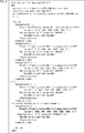
図8に示すように、MPDファイルでは、符号化ストリームごとに「AdaptationSet」が記述される。また、各「AdaptationSet」には、対応する領域のSRDが記述されるとともに、「Representation」が記述される。「Representation」には、対応する符号化ストリームの画像ファイルのURL(Uniform Resource Locator)などの情報が記述される。 As shown in FIG. 8, in the MPD file, an "Adaptation Set" is described for each encoded stream. In addition, in each "Adaptation Set", the SRD of the corresponding area is described and "Representation" is described. Information such as the URL (Uniform Resource Locator) of the image file of the corresponding coded stream is described in "Representation".
具体的には、図8の1番目の「AdaptationSet」は、全天球画像170の低解像度の全天球画像161の低解像度符号化ストリームの「AdaptationSet」である。従って、1番目の「AdaptationSet」には、低解像度の全天球画像161のSRDである<SupplementalProperty schemeIdUri="urn:mpeg:dash:srd:2014" value=“1,0,0,1920,1080,1920,1080,1"/>が記述されている。また、1番目の「AdaptationSet」の「Representation」には、低解像度符号化ストリームの画像ファイルのURL「stream1.mp4」が記述されている。
Specifically, the first "Adaptation Set" in FIG. 8 is the "Adaptation Set" of the low-resolution encoded stream of the low-resolution
図8の2番目の「AdaptationSet」は、全天球画像170の低解像度上画像の高解像度符号化ストリームの「AdaptationSet」である。従って、2番目の「AdaptationSet」には、低解像度上画像のSRDである<SupplementalProperty schemeIdUri="urn:mpeg:dash:srd:2014" value=“1,0,0,3840,540,3840,2160,2"/>が記述されている。また、2番目の「AdaptationSet」の「Representation」には、低解像度上画像の高解像度符号化ストリームの画像ファイルのURL「stream2.mp4」が記述されている。
The second "Adaptation Set" in FIG. 8 is the "Adaptation Set" of the high-resolution coded stream of the low-resolution upper image of the
また、図8の3番目の「AdaptationSet」は、全天球画像170の中央部画像174の高解像度符号化ストリームの「AdaptationSet」である。従って、3番目の「AdaptationSet」には、中央部画像174のSRDである<SupplementalProperty schemeIdUri="urn:mpeg:dash:srd:2014" value=“1,960,540,1920,1080,3840,2160,2"/>が記述されている。また、3番目の「AdaptationSet」の「Representation」には、中央部画像174の高解像度符号化ストリームの画像ファイルのURL「stream3.mp4」が記述されている。
The third "Adaptation Set" in FIG. 8 is the "Adaptation Set" of the high-resolution coded stream of the
図8の4番目の「AdaptationSet」は、全天球画像170の低解像度下画像の高解像度符号化ストリームの「AdaptationSet」である。従って、4番目の「AdaptationSet」には、低解像度下画像のSRDである<SupplementalProperty schemeIdUri="urn:mpeg:dash:srd:2014" value=“1,0,1620,3840,540,3840,2160,2"/>が記述されている。また、4番目の「AdaptationSet」の「Representation」には、低解像度下画像の高解像度符号化ストリームの画像ファイルのURL「stream4.mp4」が記述されている。
The fourth "Adaptation Set" in FIG. 8 is the "Adaptation Set" of the high-resolution coded stream of the low-resolution lower image of the
また、図8の5番目の「AdaptationSet」は、全天球画像170の端部画像173の高解像度符号化ストリームの「AdaptationSet」である。従って、5番目の「AdaptationSet」には、端部画像173のSRDである<SupplementalProperty schemeIdUri="urn:mpeg:dash:srd:2014" value=“1,2880,540,1920,1080,3840,2160,2"/>が記述されている。また、5番目の「AdaptationSet」の「Representation」には、端部画像173の高解像度符号化ストリームの画像ファイルのURL「stream5.mp4」が記述されている。
The fifth "Adaptation Set" in FIG. 8 is the "Adaptation Set" of the high-resolution coded stream of the
(画像ファイル生成部の処理の説明)
図9は、図2の画像ファイル生成部150の符号化処理を説明するフローチャートである。(Explanation of processing in the image file generator)
FIG. 9 is a flowchart illustrating the coding process of the image file generation unit 150 of FIG.
図9のステップS11において、スティッチング処理部151は、図示せぬマルチカメラから供給される全方向画像の色や明るさを同一にし、重なりを除去して接続する。スティッチング処理部151は、その結果得られる全方向画像をマッピング処理部152に供給する。 In step S11 of FIG. 9, the stitching processing unit 151 makes the colors and brightness of the omnidirectional images supplied from the multi-camera (not shown) the same, removes the overlap, and connects them. The stitching processing unit 151 supplies the resulting omnidirectional image to the mapping processing unit 152.
ステップS12において、マッピング処理部152は、スティッチング処理部151から供給される全方向画像から全天球画像170を生成し、低解像度化部153と分割部155に供給する。
In step S12, the mapping processing unit 152 generates an
ステップS13において、低解像度化部153は、マッピング処理部152から供給される全天球画像170を低解像度化し、低解像度の全天球画像161を生成する。低解像度化部153は、低解像度の全天球画像161をエンコーダ154に供給する。
In step S13, the low-resolution unit 153 reduces the resolution of the
ステップS14において、エンコーダ154は、低解像度化部153から供給される低解像度の全天球画像161を符号化し、低解像度符号化ストリームを生成する。エンコーダ154は、低解像度符号化ストリームをストレージ157に供給する。
In step S14, the encoder 154 encodes the low-resolution
ステップS15において、分割部155は、マッピング処理部152から供給される全天球画像170を上画像171、下画像172、左端部画像173−1、右端部画像173−2、および中央部画像174に分割する。分割部155は、中央部画像174をエンコーダ156−4に供給する。
In step S15, the dividing unit 155 uses the
ステップS16において、分割部155は、上画像171と下画像172を水平方向の解像度が半分になるように低解像度化する。分割部155は、その結果得られる低解像度上画像をエンコーダ156−1に供給し、低解像度化された下側の領域である低解像度下画像をエンコーダ156−2に供給する。
In step S16, the division unit 155 reduces the resolution of the
ステップS17において、分割部155は、右端部画像173−2の右端に左端部画像173−1の左端を合成し、端部画像173を生成する。分割部155は、端部画像173をエンコーダ156−3に供給する。
In step S17, the dividing portion 155 synthesizes the left end of the left end image 173-1 with the right end of the right end image 173-2 to generate the
ステップS18において、エンコーダ156−1乃至156−4は、それぞれ、分割部155から供給される、低解像度上画像、低解像度下画像、端部画像173、中央部画像174を符号化する。エンコーダ156−1乃至156−4は、その結果生成される符号化ストリームを高解像度ストリームとしてストレージ157に供給する。
In step S18, the encoders 156-1 to 156-4 encode the low-resolution upper image, the low-resolution lower image, the
ステップS19において、ストレージ157は、エンコーダ154から供給される1本の低解像度符号化ストリームと、エンコーダ156−1乃至156−4から供給される4本の高解像度符号化ストリームを記録する。 In step S19, the storage 157 records one low resolution coded stream supplied by the encoder 154 and four high resolution coded streams supplied by the encoders 156-1 to 156-4.
ステップS20において、生成部158は、ストレージ157に記録されている1本の低解像度符号化ストリームと4本の高解像度符号化ストリームを読み出し、符号化ストリームごとにセグメント単位でファイル化することにより画像ファイルを生成する。生成部158は、画像ファイルを図1のWebサーバ12に伝送し、処理を終了する。
In step S20, the generation unit 158 reads out one low-resolution coded stream and four high-resolution coded streams recorded in the storage 157, and files each coded stream in segment units to create an image. Generate a file. The generation unit 158 transmits the image file to the
(動画再生端末の機能的構成例)
図10は、図1の動画再生端末14が制御用ソフトウエア21、動画再生ソフトウエア22、およびアクセス用ソフトウエア23を実行することにより実現されるストリーミング再生部の構成例を示すブロック図である。(Example of functional configuration of video playback terminal)
FIG. 10 is a block diagram showing a configuration example of a streaming playback unit realized by the
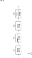
図10のストリーミング再生部190は、MPD取得部191、MPD処理部192、画像ファイル取得部193、デコーダ194−1乃至194−3、配置部195、描画部196、および視線検出部197により構成される。
The streaming
ストリーミング再生部190のMPD取得部191は、Webサーバ12からMPDファイルを取得し、MPD処理部192に供給する。
The
MPD処理部192は、視線検出部197から供給されるユーザの視線方向に基づいて、上画像171、下画像172、端部画像173、および中央部画像174から、ユーザの視野範囲に含まれる可能性のある2つを選択画像として選択する。具体的には、MPD処理部192は、全天球画像170が球の面にマッピングされたときに、球の内部に存在するユーザが視線方向を見たときに視野範囲に含まれる可能性のある、上画像171と下画像172のうちの1つと、端部画像173と中央部画像174のうちの1つとを、選択画像として選択する。
The
MPD処理部192は、MPD取得部191から供給されるMPDファイルから、再生対象のセグメントの低解像度の全天球画像161と選択画像の画像ファイルのURL等の情報を抽出し、画像ファイル取得部193に供給する。また、MPD処理部192は、MPDファイルから、再生対象のセグメントの低解像度の全天球画像161と選択画像のSRDを抽出し、配置部195に供給する。
The
画像ファイル取得部193は、MPD処理部192から供給されるURLで特定される画像ファイルの符号化ストリームをWebサーバ12に要求し、取得する。画像ファイル取得部193は、取得された低解像度符号化ストリームをデコーダ194−1に供給する。また、画像ファイル取得部193は、選択画像のうちの一方の高解像度符号化ストリームをデコーダ194−2に供給し、他方の高解像度符号化ストリームをデコーダ194−3に供給する。
The image
デコーダ194−1は、AVCやHEVCなどの符号化方式に対応する方式で、画像ファイル取得部193から供給される低解像度符号化ストリームを復号し、復号の結果得られる低解像度の全天球画像161を配置部195に供給する。
The decoder 194-1 is a method corresponding to a coding method such as AVC or HEVC, decodes the low resolution coded stream supplied from the image
また、デコーダ194−2とデコーダ194−3は、それぞれ、AVCやHEVCなどの符号化方式に対応する方式で、画像ファイル取得部193から供給される選択画像の高解像度符号化ストリームを復号する。そして、デコーダ194−2とデコーダ194−3は、復号の結果得られる選択画像を配置部195に供給する。
Further, the decoder 194-2 and the decoder 194-3 decode the high-resolution coded stream of the selected image supplied from the image
配置部195は、MPD処理部192から供給されるSRDに基づいて、デコーダ194−1から供給される低解像度の全天球画像161を画面上に配置する。その後、配置部195は、SRDに基づいて、低解像度の全天球画像161が配置された画面上に、デコーダ194−2および194−3から供給される選択画像を重畳する。
The
具体的には、SRDが示す低解像度の全天球画像161が配置される画面の水平方向および垂直方向のサイズは、選択画像が配置される画面の水平方向および垂直方向のサイズの1/2である。従って、配置部195は、低解像度の全天球画像161が配置された画面の水平方向およち垂直方向のサイズを2倍にし、選択画像を重畳する。配置部195は、選択画像が重畳された画面を球にマッピングし、その結果得られる球画像を描画部196に供給する。
Specifically, the horizontal and vertical sizes of the screen on which the low-resolution
描画部196は、配置部195から供給される球画像を、視線検出部197から供給されるユーザの視野範囲に投射投影することにより、ユーザの視野範囲の画像を生成する。描画部196は、生成された画像を表示画像として、図示せぬ表示装置に表示させる。
The
視線検出部197は、ユーザの視線方向を検出する。ユーザの視線方向の検出方法としては、例えば、ユーザに装着させた機器の傾きなどに基づいて検出する方法がある。視線検出部197は、ユーザの視線方向をMPD処理部192に供給する。
The line-of-
また、視線検出部197は、ユーザの位置を検出する。ユーザの位置の検出方法としては、例えば、ユーザに装着させた機器に付加されたマーカなどの撮影画像に基づいて検出する方法がある。視線検出部197は、検出されたユーザの位置と視線ベクトルに基づいて、ユーザの視野範囲を決定し、描画部196に供給する。
In addition, the line-of-
(動画再生端末の処理の説明)
図11は、図10のストリーミング再生部190の再生処理を説明するフローチャートである。(Explanation of processing of video playback terminal)
FIG. 11 is a flowchart illustrating the reproduction process of the
図11のステップS41において、ストリーミング再生部190のMPD取得部191は、Webサーバ12からMPDファイルを取得し、MPD処理部192に供給する。
In step S41 of FIG. 11, the
ステップS42において、MPD処理部192は、視線検出部197から供給されるユーザの視線方向に基づいて、上画像171、下画像172、端部画像173、および中央部画像174から、ユーザの視野範囲に含まれる可能性のある2つを選択画像として選択する。
In step S42, the
ステップS43において、MPD処理部192は、MPD取得部191から供給されるMPDファイルから、再生対象のセグメントの低解像度の全天球画像161と選択画像の画像ファイルのURL等の情報を抽出し、画像ファイル取得部193に供給する。
In step S43, the
ステップS44において、MPD処理部192は、MPDファイルから、再生対象のセグメントの低解像度の全天球画像161と選択画像のSRDを抽出し、配置部195に供給する。
In step S44, the
ステップS45において、画像ファイル取得部193は、MPD処理部192から供給されるURLに基づいて、そのURLで特定される画像ファイルの符号化ストリームを、Webサーバ12に要求し、取得する。画像ファイル取得部193は、取得された低解像度符号化ストリームをデコーダ194−1に供給する。また、画像ファイル取得部193は、選択画像のうちの一方の高解像度符号化ストリームをデコーダ194−2に供給し、他方の高解像度符号化ストリームをデコーダ194−3に供給する。
In step S45, the image
ステップS46において、デコーダ194−1は、画像ファイル取得部193から供給される低解像度符号化ストリームを復号し、復号の結果得られる低解像度の全天球画像161を配置部195に供給する。
In step S46, the decoder 194-1 decodes the low-resolution coded stream supplied from the image
ステップS47において、デコーダ194−2とデコーダ194−3は、それぞれ、画像ファイル取得部193から供給される選択画像の高解像度符号化ストリームを復号する。そして、デコーダ194−2とデコーダ194−3は、復号の結果得られる選択画像を配置部195に供給する。
In step S47, the decoder 194-2 and the decoder 194-3 respectively decode the high resolution encoded stream of the selected image supplied from the image
ステップS48において、配置部195は、MPD処理部192から供給されるSRDに基づいて、デコーダ194−1から供給される低解像度の全天球画像161を画面上に配置し、その後、デコーダ194−2および194−3から供給される選択画像を重畳する。配置部195は、選択画像が重畳された画面を球にマッピングし、その結果得られる球画像を描画部196に供給する。
In step S48, the
ステップS49において、描画部196は、配置部195から供給される球画像を、視線検出部197から供給されるユーザの視野範囲に投射投影することにより、表示画像を生成する。描画部196は、生成された画像を表示画像として、図示せぬ表示装置に表示させ、処理を終了する。
In step S49, the
<第2実施の形態>
(端部画像の画像ファイルのセグメント構造の例)
本開示を適用した情報処理システムの第2実施の形態は、端部画像173の符号化ストリームのうちの、左端部画像173−1の符号化ストリームと右端部画像173−2の符号化ストリームに対して異なるlevel(詳細は後述する)を設定する。これにより、SRDの定義が図7の定義である場合に、SRDを用いて、左端部画像173−1と右端部画像173−2の画面180上の位置を記述可能にする。<Second Embodiment>
(Example of segment structure of image file of edge image)
A second embodiment of the information processing system to which the present disclosure is applied is to the coded stream of the left end image 173-1 and the coded stream of the right end image 173-2 among the coded streams of the
具体的には、本開示を適用した情報処理システムの第2実施の形態は、ファイル生成装置11で生成される端部画像173の画像ファイルのセグメント構造とMPDファイルを除いて、第1実施の形態と同様である。従って、以下では、端部画像173の画像ファイルのセグメント構造とMPDファイルについてのみ説明する。
Specifically, the second embodiment of the information processing system to which the present disclosure is applied is the first embodiment except for the segment structure of the image file of the
図12は、本開示を適用した情報処理システムの第2実施の形態における端部画像173の画像ファイルのセグメント構造の例を示す図である。
FIG. 12 is a diagram showing an example of the segment structure of the image file of the
図12に示すように、端部画像173の画像ファイルでは、Initial segmentが、ftypボックスとmoovボックスにより構成される。moovボックスには、stblボックスとmvexボックスが配置される。
As shown in FIG. 12, in the image file of the
stblボックスには、端部画像173を構成する左端部画像173−1の端部画像173上の位置を示すTile Region Group Entryと、右端部画像173−2の端部画像173上の位置を示すTile Region Group Entryとが順に記述されるsgpdボックスなどが配置される。Tile Region Group Entryは、HEVC File FormatのHEVC Tile Trackで規格化されている。
The stbl box shows the Tile Region Group Entry showing the position on the
mvexボックスには、先頭のTile Region Group Entryに対応する左端部画像173−1に対するlevelとして1を設定し、2番目のTile Region Group Entryに対応する右端部画像173−2に対するlevelとして2を設定するlevaボックスなどが配置される。 In the mvex box, set 1 as the level for the leftmost image 173-1 corresponding to the first Tile Region Group Entry, and set 2 as the level for the rightmost image 173-2 corresponding to the second Tile Region Group Entry. The leva box etc. are placed.
levaボックスは、先頭のTile Region Group Entryに対応するlevelの情報、2番目のTile Region Group Entryに対応するlevelの情報を順に記述することにより、左端部画像173−1に対するlevelとして1を設定し、右端部画像173−2に対するlevelとして2を設定する。levelは、MPDファイルから、符号化ストリームの一部を指定するときにインデックスとして機能するものである。 In the leva box, 1 is set as the level for the leftmost image 173-1 by sequentially describing the level information corresponding to the first Tile Region Group Entry and the level information corresponding to the second Tile Region Group Entry. , 2 is set as the level for the rightmost image 173-2. The level functions as an index when specifying a part of the encoded stream from the MPD file.
levaボックスには、各levelの情報として、levelの設定対象が、複数のトラックに配置される符号化ストリームであるかどうかを示すassignment_typeが記述される。図12の例では、端部画像173の符号化ストリームは1つのトラックに配置される。従って、assignment_typeは、levelの設定対象が、複数のトラックに配置される符号化ストリームではないことを表す0である。
In the leva box, as information of each level, assignment_type indicating whether or not the setting target of the level is a coded stream arranged on a plurality of tracks is described. In the example of FIG. 12, the coded stream of the
また、levaボックスには、各levelの情報として、そのlevelに対応するTile Region Group Entryのタイプが記述される。図12の例では、各levelの情報として、sgpdボックスに記述されるTile Region Group Entryのタイプである「trif」が記述される。levaボックスの詳細は、例えば、ISO/IEC 14496-12 ISO base media file format 4th edition, July 2012に記述されている。 In the leva box, the type of Tile Region Group Entry corresponding to the level is described as the information of each level. In the example of FIG. 12, as the information of each level, "trif" which is the type of Tile Region Group Entry described in the sppd box is described. Details of the leva box are described, for example, in ISO / IEC 14496-12 ISO base media file format 4th edition, July 2012.
また、media segmentは、sidxボックス、ssixボックス、およびmoofとmdatのペアからなる1以上のsubsegmentにより構成される。sidxボックスには、各subsegmentの画像ファイル内の位置を示す位置情報が配置される。ssixボックスには、mdatボックスに配置される各レベルの符号化ストリームの位置情報が含まれる。 The media segment is composed of a sidx box, an ssix box, and one or more subsegments consisting of a pair of moof and mdat. In the sidx box, position information indicating the position of each subsegment in the image file is placed. The ssix box contains the location information of each level of coded stream placed in the mdat box.
subsegmentは、任意の時間長ごとに設けられる。mdatボックスには、符号化ストリームが任意の時間長分だけまとめて配置され、moofボックスには、その符号化ストリームの管理情報が配置される。 The subsegment is provided for each arbitrary time length. Encoded streams are collectively arranged in the mdat box for an arbitrary length of time, and management information of the encoded stream is arranged in the moof box.
(Tile Region Group Entryの例)
図13は、図12のTile Region Group Entryの例を示す図である。(Example of Tile Region Group Entry)
FIG. 13 is a diagram showing an example of the Tile Region Group Entry of FIG.
Tile Region Group Entryは、このTile Region Group EntryのID、対応する領域の左上の符号化ストリームに対応する画像上の水平方向および垂直方向の座標、並びに符号化ストリームに対応する画像の水平方向および垂直方向のサイズを順に記述したものである。 The Tile Region Group Entry is the ID of this Tile Region Group Entry, the horizontal and vertical coordinates on the image corresponding to the coded stream in the upper left of the corresponding area, and the horizontal and vertical coordinates of the image corresponding to the coded stream. The size of the direction is described in order.
端部画像173は、図13に示すように、960画素×1080画素の右端部画像173−2の右端に、960画素×1080画素の左端部画像173−1の左端が合成されたものである。従って、左端部画像173−1のTile Region Group Entryは、(1,960,0,960,1080)になり、右端部画像173−2のTile Region Group Entryは、(2,0,0,960,1080)になる。
As shown in FIG. 13, the
(MPDファイルの例)
図14は、MPDファイルの例を示す図である。(Example of MPD file)
FIG. 14 is a diagram showing an example of an MPD file.
図14のMPDファイルは、端部画像173の高解像度符号化ストリームの「AdaptationSet」である5番目の「AdaptationSet」を除いて、図8のMPDファイルと同一である。従って、5番目の「AdaptationSet」についてのみ説明する。
The MPD file of FIG. 14 is the same as the MPD file of FIG. 8 except for the fifth “Adaptation Set” which is the “Adaptation Set” of the high resolution encoded stream of the
図14の5番目の「AdaptationSet」には、端部画像173のSRDが記述されず、「Representation」が記述される。この「Representation」には、端部画像173の高解像度符号化ストリームの画像ファイルのURL「stream5.mp4」が記述される。また、端部画像173の符号化ストリームにはlevelが設定されるので、「Representation」には、levelごとに「SubRepresentation」が記述可能になっている。
In the fifth "Adaptation Set" of FIG. 14, the SRD of the
従って、level「1」の「SubRepresentation」には、左端部画像173−1のSRDである<SupplementalProperty schemeIdUri="urn:mpeg:dash:srd:2014" value=“1,2880,540,960,1080,3840,2160,2"/>が記述される。これにより、左端部画像173−1のSRDが、level「1」に対応するTile Region Group Entryが示す左端部画像173−1の端部画像173上の位置と対応付けて設定される。
Therefore, the "Sub Representation" of level "1" is the SRD of the leftmost image 173-1 <Supplemental Property schemeIdUri = "urn: mpeg: dash: srd: 2014" value = "1,2880,540,960,1080,3840" , 2160,2 "/> is described. As a result, the SRD of the left end image 173-1 is set in association with the position on the
また、level「2」の「SubRepresentation」には、右端部画像173−2のSRDである<SupplementalProperty schemeIdUri="urn:mpeg:dash:srd:2014" value=“1,0,540,960,1080,3840,2160,2"/>が記述される。これにより、右端部画像173−2のSRDが、level「2」に対応するTile Region Group Entryが示す右端部画像173−2の端部画像173上の位置と対応付けて設定される。
Also, in the "Sub Representation" of level "2", the SRD of the rightmost image 173-2 <Supplemental Property scheme IdUri = "urn: mpeg: dash: srd: 2014" value = "1,0,540,960,1080,3840,2160" , 2 "/> is described. As a result, the SRD of the right end image 173-2 is set in association with the position on the
以上のように、第2実施の形態では、左端部画像173−1と右端部画像173−2に対して異なるlevelが設定される。従って、符号化ストリームに対応する端部画像173を構成する左端部画像173−1と右端部画像173−2のそれぞれの画面180上の位置をSRDで記述することができる。
As described above, in the second embodiment, different levels are set for the left end image 173-1 and the right end image 173-2. Therefore, the positions on the
ストリーミング再生部190は、MPDファイルに設定されたlevel「1」のSRDに基づいて、復号された端部画像173のうちの、level「1」に対応するTile Region Group Entryが示す位置の左端部画像173−1を画面180上に配置する。また、ストリーミング再生部190は、MPDファイルに設定されたlevel「2」のSRDに基づいて、復号された端部画像173のうちの、level「2」に対応するTile Region Group Entryが示す位置の右端部画像173−2を画面180上に配置する。
The streaming
なお、第3実施の形態では、端部画像173の符号化ストリームは、1つのトラックに配置されたが、左端部画像173−1と右端部画像173−2がHEVC方式で異なるタイルとして符号化される場合には、それぞれのスライスデータが異なるトラックに配置されてもよい。
In the third embodiment, the coded stream of the
(トラック構造の例)
図15は、左端部画像173−1と右端部画像173−2のスライスデータが異なるトラックに配置される場合のトラック構造の例を示す図である。(Example of track structure)
FIG. 15 is a diagram showing an example of a track structure when the slice data of the left end image 173-1 and the right end image 173-2 are arranged on different tracks.
左端部画像173−1と右端部画像173−2のスライスデータが異なるトラックに配置される場合、図15に示すように、端部画像173の画像ファイルには、3つのトラックが配置される。
When the slice data of the left end image 173-1 and the right end image 173-2 are arranged on different tracks, three tracks are arranged in the image file of the
各トラックのtrackボックスには、Track Referenceが配置される。Track Referenceは、対応するトラックの他のトラックとの参照関係を表す。具体的には、Track Referenceは、参照関係にある他のトラックのトラックに固有のID(以下、トラックIDという)を表す。また、各トラックのサンプルは、サンプルエントリ(Sample Entry)により管理される。 A Track Reference is placed in the track box of each track. The Track Reference represents the reference relationship of the corresponding track with other tracks. Specifically, the Track Reference represents an ID unique to a track of another track having a reference relationship (hereinafter, referred to as a track ID). In addition, the sample of each track is managed by the sample entry (Sample Entry).
トラックIDが1であるトラックは、端部画像173の符号化ストリームのうちのスライスデータを含まないベーストラックである。具体的には、ベーストラックのサンプルとしては、端部画像173の符号化ストリームのうちのVPS(Video Parameter Set)、SPS(Sequence Parameter Set)、SEI(Supplemental Enhancement Information)、PPS(Picture Parameter Set)などのパラメータセットが配置される。また、ベーストラックのサンプルとしては、ベーストラック以外のトラックのサンプル単位のextractorがサブサンプルとして配置される。extractorは、extractorの種別、対応するトラックのサンプルのファイル内の位置とサイズを表す情報などにより構成される。
The track having the track ID of 1 is a base track that does not include slice data in the coded stream of the
トラックIDが2であるトラックは、端部画像173の符号化ストリームのうちの左端部画像173−1のスライスデータをサンプルとして含むトラックである。トラックIDが3であるトラックは、端部画像173の符号化ストリームのうちの右端部画像173−2のスライスデータをサンプルとして含むトラックである。
The track having the track ID of 2 is a track containing the slice data of the left end image 173-1 of the coded stream of the
(levaボックスの例)
左端部画像173−1と右端部画像173−2のスライスデータが異なるトラックに配置される場合の端部画像173の画像ファイルのセグメント構造は、levaボックスを除いて、図12のセグメント構造と同一である。従って、以下では、levaボックスについてのみ説明する。(Example of leva box)
The segment structure of the image file of the
図16は、左端部画像173−1と右端部画像173−2のスライスデータが異なるトラックに配置される場合の端部画像173の画像ファイルのlevaボックスの例を示す図である。
FIG. 16 is a diagram showing an example of a leva box of an image file of the
図16に示すように、左端部画像173−1と右端部画像173−2のスライスデータが異なるトラックに配置される場合の端部画像173の画像ファイルのlevaボックスは、トラックID「1」乃至「3」の各トラックに対して順にlevel「1」乃至「3」を設定する。
As shown in FIG. 16, when the slice data of the left end image 173-1 and the right end image 173-2 are arranged on different tracks, the leva box of the image file of the
図16のlevaボックスは、各levelの情報として、そのlevelが設定される端部画像173内の領域のスライスデータを含むトラックのトラックIDを記述する。図16の例では、level「1」、「2」、「3」の情報として、それぞれ、トラックID「1」、「2」、「3」が記述される。
The leva box of FIG. 16 describes the track ID of the track including the slice data of the area in the
また、図16の場合、levelの設定対象である端部画像173の符号化ストリームのスライスデータが、複数のトラックに配置される。従って、各levelのlevel情報に含まれるassignment_typeは、levelの設定対象が、複数のトラックに配置される符号化ストリームであることを表す2または3である。
Further, in the case of FIG. 16, the slice data of the coded stream of the
さらに、図16の場合、level「1」に対応するTile Region Group Entryは存在しない。従って、level「1」の情報に含まれるTile Region Group Entryのタイプは、Tile Region Group Entryが存在しないことを表すgrouping_type「0」である。一方、level「2」および「3」に対応するTile Region Group Entryは、sgpdボックスに含まれるTile Region Group Entryである。従って、level「2」および「3」の情報に含まれるTile Region Group Entryのタイプは、sgpdボックスに含まれるTile Region Group Entryのタイプである「trif」である。 Further, in the case of FIG. 16, there is no Tile Region Group Entry corresponding to level “1”. Therefore, the type of Tile Region Group Entry included in the information of level "1" is grouping_type "0" indicating that the Tile Region Group Entry does not exist. On the other hand, the Tile Region Group Entry corresponding to the levels "2" and "3" is the Tile Region Group Entry included in the sgpd box. Therefore, the type of Tile Region Group Entry included in the information of levels "2" and "3" is "trif" which is the type of Tile Region Group Entry included in the sgpd box.
(MPDファイルの他の例)
図17は、左端部画像173−1と右端部画像173−2のスライスデータが異なるトラックに配置される場合のMPDファイルの例を示す図である。(Other examples of MPD files)
FIG. 17 is a diagram showing an example of an MPD file when the slice data of the left end image 173-1 and the right end image 173-2 are arranged on different tracks.
図17のMPDファイルは、5番目の「AdaptationSet」の各「SubRepresentation」のelementを除いて、図14のMPDファイルと同一である。 The MPD file of FIG. 17 is the same as the MPD file of FIG. 14 except for the element of each “Sub Representation” of the fifth “Adaptation Set”.
具体的には、図17のMPDファイルでは、5番目の「AdaptationSet」の1つ目の「SubRepresentation」がlevel「2」の「SubRepresentation」である。従って、「SubRepresentation」の要素として、level「2」が記述される。 Specifically, in the MPD file of FIG. 17, the first "SubRepresentation" of the fifth "AdaptationSet" is the "SubRepresentation" of level "2". Therefore, level "2" is described as an element of "SubRepresentation".
また、level「2」に対応するトラックID「2」のトラックは、トラックID「1」のベーストラックと依存関係がある。従って、「SubRepresentation」の要素として記述される、依存関係のあるトラックに対応するlevelを表すdependencyLevelが「1」に設定する。 Further, the track with the track ID "2" corresponding to the level "2" has a dependency relationship with the base track with the track ID "1". Therefore, the dependency Level, which is described as an element of "SubRepresentation" and represents the level corresponding to the track having the dependency, is set to "1".
さらに、level「2」に対応するトラックID「2」のトラックは、HEVC Tile Trackである。従って、「SubRepresentation」の要素として記述される、符号化の種類を表すcodecsが、HEVC Tile Trackを表す「hvt1.1.2.H93.B0」に設定される。 Further, the track with the track ID “2” corresponding to the level “2” is the HEVC Tile Track. Therefore, the codecs that represent the type of encoding, which is described as an element of "Sub Representation", is set to "hvt1.1.2.H93.B0" that represents HEVC Tile Track.
また、図17のMPDファイルでは、5番目の「AdaptationSet」の2つ目の「SubRepresentation」がlevel「3」の「SubRepresentation」である。従って、「SubRepresentation」の要素として、level「3」が記述される。 Further, in the MPD file of FIG. 17, the second "SubRepresentation" of the fifth "AdaptationSet" is the "SubRepresentation" of the level "3". Therefore, level "3" is described as an element of "SubRepresentation".
また、level「3」に対応するトラックID「3」のトラックは、トラックID「1」のベーストラックと依存関係がある。従って、「SubRepresentation」の要素として記述されるdependencyLevelが「1」に設定される。 Further, the track with the track ID "3" corresponding to the level "3" has a dependency relationship with the base track with the track ID "1". Therefore, the dependencyLevel described as an element of "SubRepresentation" is set to "1".
さらに、level「3」に対応するトラックID「3」のトラックは、HEVC Tile Trackである。従って、「SubRepresentation」の要素として記述されるcodecsが「hvt1.1.2.H93.B0」に設定される。 Further, the track with the track ID “3” corresponding to the level “3” is the HEVC Tile Track. Therefore, the codecs described as the element of "SubRepresentation" is set to "hvt1.1.2.H93.B0".
上述したように、左端部画像173−1と右端部画像173−2が異なるタイルとして符号化される場合、図10のデコーダ194−2またはデコーダ194−3は、左端部画像173−1と右端部画像173−2を独立して復号することができる。また、左端部画像173−1と右端部画像173−2のスライスデータが異なるトラックに配置される場合、左端部画像173−1と右端部画像173−2のスライスデータのいずれか一方のみを取得することができる。従って、MPD処理部192は、左端部画像173−1と右端部画像173−2のうちの一方のみを選択画像として選択することができる。
As described above, when the leftmost image 173-1 and the rightmost image 173-2 are encoded as different tiles, the decoder 194-2 or the decoder 194-3 in FIG. 10 has the leftmost image 173-1 and the rightmost image 173-1. Part image 173-2 can be decoded independently. Further, when the slice data of the left end image 173-1 and the right end image 173-2 are arranged on different tracks, only one of the slice data of the left end image 173-1 and the right end image 173-2 is acquired. can do. Therefore, the
なお、上述した説明では、異なるタイルとして符号化された左端部画像173−1と右端部画像173−2のスライスデータが異なるトラックに配置されるようにしたが、1つのトラックに配置されるようにしてもよい。 In the above description, the slice data of the left end image 173-1 and the right end image 173-2 encoded as different tiles are arranged on different tracks, but they are arranged on one track. It may be.
また、第1および第3実施の形態では、動画コンテンツの画像が全天球画像であるようにしたが、パノラマ画像であってもよい。 Further, in the first and third embodiments, the image of the moving image content is a spherical image, but it may be a panoramic image.
<第3実施の形態>
(情報処理システムの第3実施の形態の構成例)
図18は、本開示を適用した情報処理システムの第3実施の形態の構成例を示すブロック図である。<Third Embodiment>
(Structure example of the third embodiment of the information processing system)
FIG. 18 is a block diagram showing a configuration example of a third embodiment of the information processing system to which the present disclosure is applied.
図18に示す構成のうち、図1の構成と同じ構成には同じ符号を付してある。重複する説明については適宜省略する。 Of the configurations shown in FIG. 18, the same configurations as those in FIG. 1 are designated by the same reference numerals. Duplicate explanations will be omitted as appropriate.
図18の情報処理システム210の構成は、ファイル生成装置11の代わりに、ファイル生成装置211が設けられる点が、図1の情報処理システム10の構成と異なる。
The configuration of the
情報処理システム210では、MPEG−DASHに準ずる方式で、Webサーバ12が、動画コンテンツの画像としてのモザイク画像の符号化ストリームを、動画再生端末14に配信する。モザイク画像とは、複数の放送番組などの動画のサムネイル画像から構成される画像である。
In the
情報処理システム210のファイル生成装置211は、複数の符号化速度(ビットレート)でモザイク画像を符号化し、符号化ストリームを生成する。ファイル生成装置211は、セグメントと呼ばれる数秒から10秒程度の時間単位ごとに、各符号化速度の符号化ストリームをファイル化し、画像ファイルを生成する。ファイル生成装置211は、生成された画像ファイルをWebサーバ12にアップロードする。
The
また、ファイル生成装置211(設定部)は、画像ファイル等を管理するMPDファイル(管理ファイル)を生成する。ファイル生成装置211は、MPDファイルをWebサーバ12にアップロードする。
Further, the file generation device 211 (setting unit) generates an MPD file (management file) for managing an image file or the like. The
(ファイル生成装置の構成例)
図19は、図18のファイル生成装置211の構成例を示すブロック図である。(Configuration example of file generator)
FIG. 19 is a block diagram showing a configuration example of the
図19のファイル生成装置211は、符号化処理部231、画像ファイル生成部232、MPD生成部233、およびサーバアップロード処理部234により構成される。
The
ファイル生成装置211の符号化処理部231は、動画コンテンツの画像としてのモザイク画像を、複数の符号化速度で符号化し、符号化ストリームを生成する。符号化処理部231は、各符号化速度の符号化ストリームを画像ファイル生成部232に供給する。
The
画像ファイル生成部232は、符号化処理部231から供給される各符号化速度の符号化ストリームを、セグメントごとにファイル化し、画像ファイルを生成する。画像ファイル生成部232は、生成された画像ファイルをMPD生成部233に供給する。
The image
MPD生成部233は、画像ファイル生成部232から供給される画像ファイルを格納するWebサーバ12のURL等を決定する。そして、MPD生成部233は、画像ファイルのURL等を含むMPDファイルを生成する。MPD生成部233は、生成されたMPDファイルと画像ファイルをサーバアップロード処理部234に供給する。
The
サーバアップロード処理部234は、MPD生成部233から供給される画像ファイルとMPDファイルを、図18のWebサーバ12にアップロードする。
The server upload
(モザイク画像の例)
図20は、モザイク画像の例を示す図である。(Example of mosaic image)
FIG. 20 is a diagram showing an example of a mosaic image.
図20の例では、モザイク画像250は、左上のサムネイル画像251、右上のサムネイル画像252、左下のサムネイル画像252、および右下のサムネイル画像254により構成される。モザイク画像250の解像度は、2k(1920画素×1080画素)であり、サムネイル画像251乃至254の解像度は、全て、960画素×540画素である。
In the example of FIG. 20, the
(sgpdボックスとlevaボックスの例)
ファイル生成装置211により生成される図20のモザイク画像250の画像ファイルのセグメント構造は、sgpdボックスとlevaボックスを除いて、図12のセグメント構造と同一である。従って、以下では、sgpdボックスとlevaボックスについてのみ説明する。(Example of sppd box and leva box)
The segment structure of the image file of the
図21は、図20のモザイク画像250の画像ファイルのsgpdボックスとlevaボックスの例を示す図である。
FIG. 21 is a diagram showing an example of a sppd box and a leva box of the image file of the
モザイク画像250は、4つのサムネイル画像251乃至254により構成されるので、図21に示すように、モザイク画像250の画像ファイルのsgpdボックスには、4つのTile Region Group Entryが記述される。
Since the
図21の例では、先頭のTile Region Group Entryは、サムネイル画像251に対応し、(1,0,0,960,540)である。2番目のTile Region Group Entryは、サムネイル画像252に対応し、(2,960,0,960,540)である。3番目のTile Region Group Entryは、サムネイル画像253に対応し、(3,0,540,960,540)である。4番目のTile Region Group Entryは、サムネイル画像254に対応し、(4,960,540,960,540)である。
In the example of FIG. 21, the head Tile Region Group Entry corresponds to the
また、levaボックスは、各Tile Region Group Entryに対応するlevelの情報を、先頭のTile Region Group Entryに対応するlevelの情報から順に記述する。これにより、サムネイル画像251に対するlevelが1に設定され、サムネイル画像252に対するlevelが2に設定され、サムネイル画像253に対するlevelが3に設定され、サムネイル画像254に対するlevelが4に設定される。
In the leva box, the level information corresponding to each Tile Region Group Entry is described in order from the level information corresponding to the first Tile Region Group Entry. As a result, the level for the
各levelの情報として記述されるassignment_typeは0に設定され、Tile Region Group Entryのタイプは、sgpdボックスに記述されるTile Region Group Entryのタイプである「trif」に設定される。 The assignment_type described as the information of each level is set to 0, and the type of Tile Region Group Entry is set to "trif" which is the type of Tile Region Group Entry described in the sppd box.
(MPDファイルの第1の例)
図22は、図18のファイル生成装置211により生成される、モザイク画像250の画像ファイルに対応するMPDファイルの第1の例を示す図である。(First example of MPD file)
FIG. 22 is a diagram showing a first example of an MPD file corresponding to the image file of the
図22に示すように、MPDファイルでは、符号化ストリームごとに「AdaptationSet」が記述される。また、「AdaptationSet」には「Representation」が記述され、「Representation」には、モザイク画像250の符号化ストリームの画像ファイルのURL「stream.mp4」が記述される。また、モザイク画像250の符号化ストリームにはlevelが設定されるので、「Representation」には、levelごとに「SubRepresentation」が記述可能になっている。
As shown in FIG. 22, in the MPD file, an "Adaptation Set" is described for each encoded stream. Further, "Representation" is described in "Adaptation Set", and the URL "stream.mp4" of the image file of the coded stream of the
従って、level「1」の「SubRepresentation」には、サムネイル画像251のSRDである<SupplementalProperty schemeIdUri="urn:mpeg:dash:srd:2014" value=“1,0,0,960,540,1920,1080"/>が記述される。これにより、サムネイル画像251のSRDが、level「1」に対応するTile Region Group Entryが示すサムネイル画像251のモザイク画像250上の位置と対応付けて設定される。
Therefore, in the "Sub Representation" of level "1", the SRD of the
また、level「2」の「SubRepresentation」には、サムネイル画像252のSRDである<SupplementalProperty schemeIdUri="urn:mpeg:dash:srd:2014" value=“1,960,0,960,540,1920,1080"/>が記述される。これにより、サムネイル画像252のSRDが、level「2」に対応するTile Region Group Entryが示すサムネイル画像252のモザイク画像250上の位置と対応付けて設定される。
In addition, <Supplemental Property schemeIdUri = "urn: mpeg: dash: srd: 2014" value = "1,960,0,960,540,1920,1080" />, which is the SRD of the
さらに、level「3」の「SubRepresentation」には、サムネイル画像253のSRDである<SupplementalProperty schemeIdUri="urn:mpeg:dash:srd:2014" value=“1,0,540,960,540,1920,1080"/>が記述される。これにより、サムネイル画像253のSRDが、level「3」に対応するTile Region Group Entryが示すサムネイル画像253のモザイク画像250上の位置と対応付けて設定される。
Furthermore, in the "Sub Representation" of level "3", the SRD of the
また、level「4」の「SubRepresentation」には、サムネイル画像254のSRDである<SupplementalProperty schemeIdUri="urn:mpeg:dash:srd:2014" value=“1,960,540,960,540,1920,1080"/>が記述される。これにより、サムネイル画像254のSRDが、level「4」に対応するTile Region Group Entryが示すサムネイル画像254のモザイク画像250上の位置と対応付けて設定される。
In addition, <Supplemental Property schemeIdUri = "urn: mpeg: dash: srd: 2014" value = "1,960,540,960,540,1920,1080" />, which is the SRD of the
以上のように、図22のMPDファイルでは、Tile Region Group Entryが示すモザイク画像250の水平方向および垂直方向のサイズと、SRDが示す画面の水平方向および垂直方向のサイズが同一である。また、各levelに対応するTile Region Group Entryが示すモザイク画像250上の水平方向および垂直方向の座標と、そのlevelに対応するSRDが示す画面上の水平方向および垂直方向の位置が同一である。従って、図22のMPDファイルが生成される場合、SRDに基づいて復号されたサムネイル画像251乃至254が配置された画面は、モザイク画像250と同一になる。
As described above, in the MPD file of FIG. 22, the horizontal and vertical sizes of the
また、各levelの「SubRepresentation」には、そのlevelのサムネイル画像251乃至254に対応する動画のURLも記述される。具体的には、level「1」の「SubRepresentation」には、サムネイル画像251に対応する動画のURL「http://example.com/a_service/my.mpd」が記述される。また、level「2」の「SubRepresentation」には、サムネイル画像252に対応する動画のURL「http://example.com/b_service/my.mpd」が記述される。
Further, in the "SubRepresentation" of each level, the URL of the moving image corresponding to the
また、level「3」の「SubRepresentation」には、サムネイル画像253に対応する動画のURL「http://example.com/c_service/my.mpd」が記述される。また、level「4」の「SubRepresentation」には、サムネイル画像254に対応する動画のURL「http://example.com/d_service/my.mpd」が記述される。
Further, in the "SubRepresentation" of the level "3", the URL "http://example.com/c_service/my.mpd" of the video corresponding to the
(MPDファイルの第2の例)
図23は、図18のファイル生成装置211により生成される、モザイク画像250の画像ファイルに対応するMPDファイルの第2の例を示す図である。(Second example of MPD file)
FIG. 23 is a diagram showing a second example of the MPD file corresponding to the image file of the
なお、図23のMPDファイルは、各levelの「SubRepresentation」に記述されるSRDのみが図22のMPDと異なっている。 The MPD file of FIG. 23 differs from the MPD of FIG. 22 only in the SRD described in the “Sub Representation” of each level.
即ち、図23のMPDファイルでは、level「3」の「SubRepresentation」には、サムネイル画像253のSRDである<SupplementalProperty schemeIdUri="urn:mpeg:dash:srd:2014" value=“1,0,0,960,540,1920,1080"/>が記述される。
That is, in the MPD file of FIG. 23, the "SubRepresentation" of level "3" is the SRD of the
また、level「4」の「SubRepresentation」には、サムネイル画像254のSRDである<SupplementalProperty schemeIdUri="urn:mpeg:dash:srd:2014" value=“1,960,0,960,540,1920,1080"/>が記述される。
In addition, <Supplemental Property schemeIdUri = "urn: mpeg: dash: srd: 2014" value = "1,960,0,960,540,1920,1080" />, which is the SRD of the
さらに、level「1」の「SubRepresentation」には、サムネイル画像251のSRDである<SupplementalProperty schemeIdUri="urn:mpeg:dash:srd:2014" value=“1,0,540,960,540,1920,1080"/>が記述される。
Further, in "SubRepresentation" of level "1", <Supplemental Property schemeIdUri = "urn: mpeg: dash: srd: 2014" value = "1,0,540,960,540,1920,1080" /> which is SRD of
また、level「2」の「SubRepresentation」には、サムネイル画像252のSRDである<SupplementalProperty schemeIdUri="urn:mpeg:dash:srd:2014" value=“1,960,540,960,540,1920,1080"/>が記述される。
In addition, <Supplemental Property schemeIdUri = "urn: mpeg: dash: srd: 2014" value = "1,960,540,960,540,1920,1080" />, which is the SRD of the
以上のように、図23のMPDファイルでは、図22のMPDファイルと同様に、Tile Region Group Entryが示すモザイク画像250の水平方向および垂直方向のサイズと、SRDが示す画面の水平方向および垂直方向のサイズが同一である。
As described above, in the MPD file of FIG. 23, the horizontal and vertical sizes of the
しかしながら、各levelに対応するTile Region Group Entryが示すモザイク画像250上の水平方向および垂直方向の座標と、そのlevelに対応するSRDが示す画面上の水平方向および垂直方向の位置が異なっている。従って、図23のMPDファイルが生成される場合、SRDに基づいて復号されたサムネイル画像251乃至254が配置された画面は、モザイク画像250と異なる。
However, the horizontal and vertical coordinates on the
(サムネイル画像が配置された画面の例)
図24は、図23のMPDファイルに記述されたSRDに基づいて復号されたサムネイル画像251乃至254が配置された画面の例を示す図である。(Example of screen where thumbnail images are arranged)
FIG. 24 is a diagram showing an example of a screen in which
図23のMPDファイルに記述されたサムネイル画像251のSRDは、サムネイル画像251の左上の、1920画素×1080画素からなる画面270上の座標が(0,540)である。従って、図24に示すように、サムネイル画像251は、画面270の左下に配置される。
The SRD of the
また、サムネイル画像252のSRDは、サムネイル画像252の左上の画面270上の座標が(960,0)である。従って、図24に示すように、サムネイル画像252は、画面270の右下に配置される。
Further, in the SRD of the
さらに、サムネイル画像253のSRDは、サムネイル画像253の左上の、1920画素×1080画素からなる画面270上の座標が(0,0)である。従って、図24に示すように、サムネイル画像253は、画面270の左上に配置される。
Further, in the SRD of the
また、サムネイル画像254のSRDは、サムネイル画像254の左上の画面270上の座標が(960,0)である。従って、図24に示すように、サムネイル画像254は、画面270の右上に配置される。
Further, in the SRD of the
以上のように、図23のMPDファイルにより、表示時に、サムネイル画像251乃至254の配置を、符号化対象のモザイク画像250における配置から、画面270における配置に変更することができる。
As described above, with the MPD file of FIG. 23, the arrangement of the
(ファイル生成装置の処理の説明)
図25は、図19のファイル生成装置211のファイル生成処理を説明するフローチャートである。(Explanation of processing of file generator)
FIG. 25 is a flowchart illustrating the file generation process of the
図25のステップS191において、符号化処理部231は、動画コンテンツの画像としてのモザイク画像を複数の符号化速度で符号化し、符号化ストリームを生成する。符号化処理部231は、各符号化速度の符号化ストリームを画像ファイル生成部232に供給する。
In step S191 of FIG. 25, the
ステップS192において、画像ファイル生成部232は、符号化処理部231から供給される各符号化速度の符号化ストリームを、セグメントごとにファイル化し、画像ファイルを生成する。画像ファイル生成部232は、生成された画像ファイルをMPD生成部233に供給する。
In step S192, the image
ステップS193において、MPD生成部233は、画像ファイルのURL等を含むMPDファイルを生成する。MPD生成部233は、生成されたMPDファイルと画像ファイルをサーバアップロード処理部234に供給する。
In step S193, the
ステップS194において、サーバアップロード処理部234は、MPD生成部233から供給される画像ファイルとMPDファイルを、Webサーバ12にアップロードする。そして、処理は終了する。
In step S194, the server upload
(動画再生端末の機能的構成例)
図26は、図18の動画再生端末14が制御用ソフトウエア21、動画再生ソフトウエア22、およびアクセス用ソフトウエア23を実行することにより実現されるストリーミング再生部の構成例を示すブロック図である。(Example of functional configuration of video playback terminal)
FIG. 26 is a block diagram showing a configuration example of a streaming playback unit realized by the
なお、図26に示す構成のうち、図10の構成と同じ構成には同じ符号を付してある。重複する説明については適宜省略する。 Of the configurations shown in FIG. 26, the same configurations as those in FIG. 10 are designated by the same reference numerals. Duplicate explanations will be omitted as appropriate.
図26のストリーミング再生部290は、MPD取得部191、MPD処理部292、画像ファイル取得部293、デコーダ294、表示制御部295、受付部296、および動画取得部297により構成される。
The streaming
ストリーミング再生部290のMPD処理部292は、MPD取得部191から供給されるMPDファイルから再生対象のセグメントの画像ファイルのURL等の情報を抽出し、画像ファイル取得部293に供給する。また、MPD処理部292は、MPDファイルを動画取得部297に供給する。さらに、MPD処理部292は、MPDファイルから再生対象のセグメントのモザイク画像の各分割画像のSRDを抽出し、表示制御部295に供給する。
The
画像ファイル取得部293は、MPD処理部292から供給されるURLで特定される画像ファイルの符号化ストリームを、Webサーバ12に要求し、取得する。画像ファイル取得部293は、取得された符号化ストリームをデコーダ294に供給する。
The image
デコーダ294は、画像ファイル取得部293から供給される符号化ストリームを復号する。デコーダ294は、復号の結果得られるモザイク画像を表示制御部295に供給する。
The
表示制御部295(配置部)は、MPD処理部292から供給されるSRDに基づいて、デコーダ294から供給されるモザイク画像の各分割画像を画面上に配置する。また、表示制御部295は、各分割画像に配置された画面にカーソル等を重畳して、図示せぬ表示装置に供給し、表示させる。
The display control unit 295 (arrangement unit) arranges each divided image of the mosaic image supplied from the
また、表示制御部295は、受付部296から供給される画面の所定の領域の拡大指示に応じて、モザイク画像が配置された画面のうちの、その領域に含まれるサムネイル画像のみからなる部分モザイク画像のサイズを、画面サイズに拡大する。そして、表示制御部295は、拡大された部分モザイク画像が配置された画面内の所定のサムネイル画像にカーソル等を重畳し、図示せぬ表示装置に供給して、表示させる。
Further, the
また、表示制御部295は、動画取得部297から供給される、表示中のサムネイル画像の1つに対応する動画を、図示せぬ表示装置に供給し、表示させる。
Further, the
受付部296は、ユーザ等からの指示を受け付け、その指示を動画取得部297または表示制御部295に供給する。
The
動画取得部297は、受付部296から供給される所定の位置の指示に応じて、MPD処理部292から供給されるMPDファイルから、その位置に対応する動画のURLを取得する。動画取得部297は、取得されたURLに基づいて、Webサーバ12等から動画を取得し、表示制御部295に供給する。
The moving
(再生処理の概要)
図27は、図26のストリーミング再生部290による再生処理の概要を説明する図である。(Overview of playback process)
FIG. 27 is a diagram illustrating an outline of the reproduction process by the streaming
図27の左側に示すように、表示制御部295は、まず、画面に配置されたモザイク画像310を構成する4×4個のサムネイル画像311のうちの、所定のサムネイル画像311にカーソル312を重畳し、図示せぬ表示装置に表示させる。
As shown on the left side of FIG. 27, the
このとき、ユーザは、カーソル312が重畳されたモザイク画像310の画面を見ながら、所望の領域の拡大指示を行う。図27の例では、ユーザは、モザイク画像310が配置された画面の右上の2×2個のサムネイル画像311の領域の拡大指示を行っている。
At this time, the user gives an instruction to enlarge a desired area while looking at the screen of the
表示制御部295は、この拡大指示に応じて、モザイク画像310が配置された画面のうちの右上の2×2個のサムネイル画像311のみからなる部分モザイク画像313のサイズを、画面サイズに拡大する。そして、図27の中央に示すように、表示制御部295は、拡大された部分モザイク画像313が配置された画面内の所定のサムネイル画像311にカーソル314を重畳し、図示せぬ表示装置に表示させる。
In response to this enlargement instruction, the
このとき、ユーザは、カーソル314を所望のサムネイル画像311に移動させ、ダブルタップ等の操作を行うことにより、カーソル314の位置を指示する。図27の例では、ユーザは、右上のサムネイル画像311の位置を指示している。
At this time, the user moves the
動画取得部297は、その指示に応じて、MPDファイルから、指示された部分モザイク画像313上の位置に対応するモザイク画像310の画面上の位置を示すSRDに対応する動画のURLを、指示された位置に対応する動画のURLとして取得する。そして、動画取得部297は、取得されたURLに基づいて、Webサーバ12等から動画315を取得し、表示制御部295に供給する。これにより、図27の右側に示すように、表示制御部295は、動画315を図示せぬ表示装置に表示させる。
In response to the instruction, the
(動画再生端末の処理の説明)
図28は、図26のストリーミング再生部290の再生処理を説明するフローチャートである。(Explanation of processing of video playback terminal)
FIG. 28 is a flowchart illustrating the reproduction process of the
図28のステップS211において、ストリーミング再生部290のMPD取得部191は、Webサーバ12からMPDファイルを取得し、MPD処理部292に供給する。
In step S211 of FIG. 28, the
ステップS212において、MPD処理部292は、MPD取得部191から供給されるMPDファイルか再生対象のセグメントの画像ファイルのURL等の情報を抽出し、画像ファイル取得部293に供給する。また、MPD処理部292は、MPDファイルを動画取得部297に供給する。さらに、MPD処理部292は、MPDファイルから再生対象のセグメントのモザイク画像の各分割画像のSRDを抽出し、表示制御部295に供給する。
In step S212, the
ステップS213において、画像ファイル取得部293は、MPD処理部292から供給されるURLに基づいて、そのURLで特定される画像ファイルの符号化ストリームを、Webサーバ12に要求し、取得する。画像ファイル取得部293は、取得された符号化ストリームをデコーダ294に供給する。
In step S213, the image
ステップS214において、デコーダ294は、画像ファイル取得部293から供給される符号化ストリームを復号する。デコーダ294は、復号の結果得られるモザイク画像を表示制御部295に供給する。
In step S214, the
ステップS215において、表示制御部295は、MPD処理部292からのSRDに基づいて、デコーダ294からのモザイク画像の各分割画像を画面上に配置し、その画面にカーソル等を重畳して、図示せぬ表示装置に供給し、表示させる。
In step S215, the
ステップS216において、受付部296は、ユーザからの画面の所定の領域の拡大指示を受け付けたかどうかを判定する。ステップS216で画面の所定の領域の拡大指示を受け付けていないと判定された場合、受付部296は、画面の所定の領域の拡大指示を受け付けるまで待機する。
In step S216, the
一方、ステップS216で画面の所定の領域の拡大指示を受け付けたと判定された場合、受付部296は、その拡大指示を表示制御部295に供給する。そして、ステップS217において、表示制御部295は、受付部296から供給される拡大指示に応じて、モザイク画像が配置された画面のうちの、拡大指示された領域に含まれるサムネイル画像のみからなる部分モザイク画像のサイズを、画面サイズに拡大する。
On the other hand, when it is determined in step S216 that an enlargement instruction for a predetermined area of the screen has been received, the
ステップS218において、表示制御部295は、拡大された部分モザイク画像が配置された画面内の所定のサムネイル画像にカーソル等を重畳し、図示せぬ表示装置に供給して、表示させる。このとき、ユーザは、カーソルを所望のサムネイル画像に移動させ、ダブルタップ等の操作を行うことにより、画面上のカーソルの位置を指示する。
In step S218, the
ステップS219において、受付部296は、ユーザからの画面上の位置の指示を受け付けたかどうかを判定する。ステップS219で画面上の位置の指示を受け付けていないと判定された場合、受付部296は、画面上の位置の指示を受け付けるまで待機する。
In step S219, the
一方、ステップS219で画面上の位置の指示を受け付けたと判定された場合、受付部296は、その指示を動画取得部297に供給する。そして、ステップS220において、動画取得部297は、受付部296から供給される指示に応じて、MPD処理部292から供給されるMPDファイルから、指示された位置に対応する動画のURLを取得する。
On the other hand, when it is determined in step S219 that the instruction of the position on the screen has been received, the
ステップS221において、動画取得部297は、取得されたURLに基づいて、Webサーバ12等から動画を取得し、表示制御部295に供給する。
In step S221, the moving
ステップS222において、表示制御部295は、動画取得部297から供給される動画を、図示せぬ表示装置に供給し、表示させる。そして、処理は終了する。
In step S222, the
なお、第3実施の形態では、モザイク画像の表示後に部分モザイク画像が表示され、ユーザにより部分モザイク画像上の位置が指示されるようにしたが、部分モザイク画像は表示されず、モザイク画像上の位置が直接ユーザにより指示されるようにしてもよい。 In the third embodiment, the partial mosaic image is displayed after the mosaic image is displayed, and the user indicates the position on the partial mosaic image. However, the partial mosaic image is not displayed and the partial mosaic image is displayed on the mosaic image. The position may be directly indicated by the user.
<第4実施の形態>
(本開示を適用したコンピュータの説明)
上述した一連の処理は、ハードウエアにより実行することもできるし、ソフトウエアにより実行することもできる。一連の処理をソフトウエアにより実行する場合には、そのソフトウエアを構成するプログラムが、コンピュータにインストールされる。ここで、コンピュータには、専用のハードウエアに組み込まれているコンピュータや、各種のプログラムをインストールすることで、各種の機能を実行することが可能な、例えば汎用のパーソナルコンピュータなどが含まれる。<Fourth Embodiment>
(Description of the computer to which this disclosure is applied)
The series of processes described above can be executed by hardware or by software. When a series of processes are executed by software, the programs constituting the software are installed on the computer. Here, the computer includes a computer embedded in dedicated hardware and, for example, a general-purpose personal computer capable of executing various functions by installing various programs.
図29は、上述した一連の処理をプログラムにより実行するコンピュータのハードウエアの構成例を示すブロック図である。 FIG. 29 is a block diagram showing a configuration example of hardware of a computer that executes the above-mentioned series of processes programmatically.
コンピュータ900において、CPU(Central Processing Unit)901,ROM(Read Only Memory)902,RAM(Random Access Memory)903は、バス904により相互に接続されている。
In the
バス904には、さらに、入出力インタフェース905が接続されている。入出力インタフェース905には、入力部906、出力部907、記憶部908、通信部909、及びドライブ910が接続されている。
An input /
入力部906は、キーボード、マウス、マイクロフォンなどよりなる。出力部907は、ディスプレイ、スピーカなどよりなる。記憶部908は、ハードディスクや不揮発性のメモリなどよりなる。通信部909は、ネットワークインタフェースなどよりなる。ドライブ910は、磁気ディスク、光ディスク、光磁気ディスク、又は半導体メモリなどのリムーバブルメディア911を駆動する。
The
以上のように構成されるコンピュータ900では、CPU901が、例えば、記憶部908に記憶されているプログラムを、入出力インタフェース905及びバス904を介して、RAM903にロードして実行することにより、上述した一連の処理が行われる。
In the
コンピュータ900(CPU901)が実行するプログラムは、例えば、パッケージメディア等としてのリムーバブルメディア911に記録して提供することができる。また、プログラムは、ローカルエリアネットワーク、インターネット、デジタル衛星放送といった、有線または無線の伝送媒体を介して提供することができる。
The program executed by the computer 900 (CPU901) can be recorded and provided on the
コンピュータ900では、プログラムは、リムーバブルメディア911をドライブ910に装着することにより、入出力インタフェース905を介して、記憶部908にインストールすることができる。また、プログラムは、有線または無線の伝送媒体を介して、通信部909で受信し、記憶部908にインストールすることができる。その他、プログラムは、ROM902や記憶部908に、あらかじめインストールしておくことができる。
In the
なお、コンピュータ900が実行するプログラムは、本明細書で説明する順序に沿って時系列に処理が行われるプログラムであっても良いし、並列に、あるいは呼び出しが行われたとき等の必要なタイミングで処理が行われるプログラムであっても良い。
The program executed by the
また、本明細書において、システムとは、複数の構成要素(装置、モジュール(部品)等)の集合を意味し、すべての構成要素が同一筐体中にあるか否かは問わない。したがって、別個の筐体に収納され、ネットワークを介して接続されている複数の装置、及び、1つの筐体の中に複数のモジュールが収納されている1つの装置は、いずれも、システムである。 Further, in the present specification, the system means a set of a plurality of components (devices, modules (parts), etc.), and it does not matter whether or not all the components are in the same housing. Therefore, a plurality of devices housed in separate housings and connected via a network, and a device in which a plurality of modules are housed in one housing are both systems. ..
なお、本明細書に記載された効果はあくまで例示であって限定されるものではなく、他の効果があってもよい。 The effects described in the present specification are merely examples and are not limited, and other effects may be obtained.
また、本開示の実施の形態は、上述した実施の形態に限定されるものではなく、本開示の要旨を逸脱しない範囲において種々の変更が可能である。 Further, the embodiment of the present disclosure is not limited to the above-described embodiment, and various changes can be made without departing from the gist of the present disclosure.
なお、本開示は、以下のような構成もとることができる。 The present disclosure may have the following structure.
(1)
符号化ストリームに対応する複数の分割画像からなる画像の画面上の位置として、前記画面の外側にはみ出る位置を設定する設定部
を備える情報処理装置。
(2)
前記複数の分割画像は、全天球画像またはパノラマ画像の一部を構成する対向する端部の画像である
ように構成された
前記(1)に記載の情報処理装置。
(3)
前記設定部は、前記符号化ストリームのファイルを管理する管理ファイルに前記画像の前記画面上の位置を設定する
ように構成された
前記(1)または(2)に記載の情報処理装置。
(4)
情報処理装置が、
符号化ストリームに対応する、複数の分割画像からなる画像の画面上の位置として、前記画面の外側にはみ出る位置を設定する設定ステップ
を含む情報処理方法。
(5)
符号化ストリームに対応する複数の分割画像からなる画像の画面上の位置として設定された前記画面の外側にはみ出る位置に基づいて、前記符号化ストリームを復号することにより得られた前記画像を前記画面上に配置する配置部
を備える情報処理装置。
(6)
前記複数の分割画像は、全天球画像またはパノラマ画像の一部を構成する対向する端部の画像である
ように構成された
前記(5)に記載の情報処理装置。
(7)
前記画像の前記画面上の位置は、前記符号化ストリームのファイルを管理する管理ファイルに設定される
ように構成された
前記(5)または(6)に記載の情報処理装置。
(8)
情報処理装置が、
符号化ストリームに対応する複数の分割画像からなる画像の画面上の位置として設定された前記画面の外側にはみ出る位置に基づいて、前記符号化ストリームを復号することにより得られた前記画像を前記画面上に配置する配置ステップ
を含む情報処理方法。
(9)
符号化ストリームに対応する複数の分割画像からなる画像の各分割画像の画面上の位置を、その分割画像の前記画像上の位置と対応付けて設定する設定部
を備える情報処理装置。
(10)
前記画像は、全天球画像またはパノラマ画像の一部、もしくは、モザイク画像である
ように構成された
前記(9)に記載の情報処理装置。
(11)
前記符号化ストリームは、各分割画像を異なるタイルとして符号化した符号化ストリームである
ように構成された
前記(9)または(10)に記載の情報処理装置。
(12)
前記設定部は、前記符号化ストリームのファイルを管理する管理ファイルに前記画像の前記画面上の位置を設定する
ように構成された
前記(9)乃至(11)のいずれかに記載の情報処理装置。
(13)
情報処理装置が、
符号化ストリームに対応する複数の分割画像からなる画像の各分割画像の画面上の位置を、その分割画像の前記画像上の位置と対応付けて設定する設定ステップ
を含む情報処理方法。
(14)
符号化ストリームに対応する複数の分割画像からなる画像上の位置と対応付けて設定された、前記画像の各分割画像の画面上の位置に基づいて、前記符号化ストリームを復号することにより得られた前記画像の各分割画像を前記画面上に配置する配置部
を備える情報処理装置。
(15)
前記画像は、全天球画像またはパノラマ画像の一部、もしくは、モザイク画像である
ように構成された
前記(14)に記載の情報処理装置。
(16)
前記符号化ストリームは、各分割画像を異なるタイルとして符号化した符号化ストリームである
ように構成された
前記(14)または(15)に記載の情報処理装置。
(17)
前記画像の前記画面上の位置は、前記符号化ストリームのファイルを管理する管理ファイルに設定される
ように構成された
前記(14)乃至(16)のいずれかに記載の情報処理装置。
(18)
情報処理装置が、
符号化ストリームに対応する複数の分割画像からなる画像上の位置と対応付けて設定された、前記画像の各分割画像の画面上の位置に基づいて、前記符号化ストリームを復号することにより得られた前記画像の各分割画像を前記画面上に配置する配置ステップ
を含む情報処理方法。(1)
An information processing device including a setting unit that sets a position on the screen of an image composed of a plurality of divided images corresponding to a coded stream, which extends outside the screen.
(2)
The information processing apparatus according to (1) above, wherein the plurality of divided images are configured so as to be images of opposite ends forming a part of a spherical image or a panoramic image.
(3)
The information processing apparatus according to (1) or (2), wherein the setting unit is configured to set a position of the image on the screen in a management file that manages a file of the coded stream.
(4)
Information processing device
An information processing method including a setting step of setting a position on the screen of an image composed of a plurality of divided images corresponding to a coded stream, which extends outside the screen.
(5)
The image obtained by decoding the coded stream is displayed on the screen based on a position set as a position on the screen of an image composed of a plurality of divided images corresponding to the coded stream and protruding outside the screen. An information processing device that has an arrangement unit that is arranged on top.
(6)
The information processing apparatus according to (5) above, wherein the plurality of divided images are configured so as to be images of opposite ends forming a part of a spherical image or a panoramic image.
(7)
The information processing apparatus according to (5) or (6) above, wherein the position of the image on the screen is set to a management file that manages a file of the coded stream.
(8)
Information processing device
The image obtained by decoding the coded stream is displayed on the screen based on a position set as a position on the screen of an image composed of a plurality of divided images corresponding to the coded stream and protruding outside the screen. An information processing method that includes a placement step to place on top.
(9)
An information processing device including a setting unit that sets a position on the screen of each divided image of an image composed of a plurality of divided images corresponding to a coded stream in association with the position of the divided image on the image.
(10)
The information processing device according to (9) above, wherein the image is a part of a spherical image or a panoramic image, or a mosaic image.
(11)
The information processing apparatus according to (9) or (10) above, wherein the coded stream is configured to be a coded stream in which each divided image is encoded as a different tile.
(12)
The information processing apparatus according to any one of (9) to (11), wherein the setting unit is configured to set the position of the image on the screen in a management file that manages a file of the coded stream. ..
(13)
Information processing device
An information processing method including a setting step of setting a position on the screen of each divided image of an image composed of a plurality of divided images corresponding to a coded stream in association with the position of the divided image on the image.
(14)
Obtained by decoding the coded stream based on the position on the screen of each divided image of the image, which is set in association with the position on the image consisting of a plurality of divided images corresponding to the coded stream. An information processing device including an arrangement unit for arranging each divided image of the image on the screen.
(15)
The information processing device according to (14) above, wherein the image is a part of a spherical image or a panoramic image, or a mosaic image.
(16)
The information processing apparatus according to (14) or (15) above, wherein the coded stream is configured to be a coded stream in which each divided image is encoded as a different tile.
(17)
The information processing apparatus according to any one of (14) to (16), wherein the position of the image on the screen is set in a management file that manages a file of the coded stream.
(18)
Information processing device
Obtained by decoding the coded stream based on the position on the screen of each divided image of the image, which is set in association with the position on the image consisting of a plurality of divided images corresponding to the coded stream. An information processing method including an arrangement step of arranging each divided image of the image on the screen.
11 ファイル生成装置, 14 動画再生端末, 170 全天球画像, 173−1 左端部画像,173−2 右端部画像, 180 画面, 195 配置部, 211 ファイル生成装置, 250 モザイク画像, 251乃至254 サムネイル画像 11 File generator, 14 Video playback terminal, 170 Spherical image, 173-1 Left edge image, 173-2 Right edge image, 180 screen, 195 Arrangement, 211 File generator, 250 Mosaic image, 251 to 254 thumbnails image
Claims (8)
前記端部画像が、前記第1の分割画像と前記第2の分割画像とを含むことを表す画像情報を生成する設定部と
を備える情報処理装置。 It is a division unit that generates a plurality of divided images divided vertically and horizontally with respect to a developed image obtained by developing a 360-degree image in the horizontal direction on a plane, and among the divided images, the developed image. The first divided image arranged at one end in the horizontal direction of the above is projected outside the developed image with respect to the second divided image arranged at the other end facing the one end. A division portion that is arranged at a position to generate an end image that combines the first divided image and the second divided image, and a divided portion.
Said end image, the information processing apparatus and a setting unit that generates image information indicating that comprises a second divided image and the first divided image.
請求項1に記載の情報処理装置。 The developed image is Ru Ah at full spherical image or a panoramic image image
The information processing apparatus according to請Motomeko 1.
前記設定部は、前記符号化ストリームのファイルを管理する管理ファイルに前記画像情報、及び、前記分割画像の前記展開画像の画面上の位置を表す情報を含める
請求項1に記載の情報処理装置。 The divided image is an image corresponding to the coded stream.
The setting unit, the image information management file for managing files of the coded stream, and information processing apparatus according to claim 1 including the information indicating a position on the screen of the expanded image of the divided image ..
設定部と
を備えた
情報処理装置の
前記分割部は、水平方向の周囲360度の画像を平面に展開した展開画像に対して、垂直方向および水平方向にそれぞれ分割した複数の分割画像を生成し、
前記分割画像のうち、前記展開画像の水平方向の一方の端部に配置された第1の分割画像を、前記一方の端部と対向する他方の端部に配置された第2の分割画像に対して前記展開画像の外側にはみ出る位置に配置して、前記第1の分割画像と前記第2の分割画像とを合成した端部画像を生成し、
前記設定部は、前記端部画像が、前記第1の分割画像と前記第2の分割画像とを含むことを表す画像情報を生成する
情報処理方法。 Divided part and
With the setting part
The information processing apparatus including
The divided portion generates a plurality of divided images divided in the vertical direction and the horizontal direction with respect to the developed image obtained by developing the image having a 360-degree circumference in the horizontal direction on a plane.
Of the divided images, the first divided image arranged at one end in the horizontal direction of the developed image is converted into a second divided image arranged at the other end facing the one end. On the other hand, it is arranged at a position protruding outside the developed image to generate an end image obtained by synthesizing the first divided image and the second divided image.
The setting unit is an information processing method for generating image information indicating that the end image includes the first divided image and the second divided image .
前記分割画像の前記展開画像の画面上の位置を表した画像情報に基づいて前記分割画像を前記画面上に配置する配置部
を備える情報処理装置。 A plurality of divided images divided vertically and horizontally with respect to a developed image obtained by developing a 360-degree image in the horizontal direction on a plane, and arranged at one end in the horizontal direction of the developed image. The first divided image is arranged at a position protruding outside the developed image with respect to the second divided image arranged at the other end facing the one end , and the first With respect to the divided image including the end image in which the divided image and the second divided image are combined,
An information processing device including an arrangement unit for arranging the divided image on the screen based on image information representing the position of the expanded image on the screen of the divided image.
請求項5に記載の情報処理装置。 The developed image is Ru Ah at full spherical image or a panoramic image image
The information processing apparatus according to請Motomeko 5.
前記分割画像の前記画面上の位置は、前記符号化ストリームのファイルを管理する管理ファイルに設定される
ように構成された
請求項5に記載の情報処理装置。 The divided image is an image corresponding to the coded stream.
The information processing apparatus according to claim 5, wherein the position of the divided image on the screen is set in a management file that manages a file of the coded stream.
を備えた
情報処理装置の
前記配置部が、水平方向の周囲360度の画像を平面に展開した展開画像に対して、垂直方向および水平方向にそれぞれ分割された複数の分割画像であって、前記展開画像の水平方向の一方の端部に配置された第1の分割画像が、前記一方の端部と対向する他方の端部に配置された第2の分割画像に対して前記展開画像の外側にはみ出る位置に配置されて、前記第1の分割画像と前記第2の分割画像とが合成された端部画像を含む分割画像に対して、
前記分割画像の前記展開画像の画面上の位置を表した画像情報に基づいて前記分割画像を前記画面上に配置する
情報処理方法。 Placement part
The information processing apparatus including
The arrangement portion is a plurality of divided images divided in the vertical direction and the horizontal direction with respect to the developed image obtained by developing the image having a circumference of 360 degrees in the horizontal direction on a plane, and is one of the horizontal directions of the developed image. first divided images arranged in the end portion, is disposed at a position protruding outside the developed image to the second divided images arranged at the other end opposite to the one end , With respect to the divided image including the end image in which the first divided image and the second divided image are combined.
Place the divided images on the screen based on the image information representing the position on the screen of the expanded image of the divided image
Information processing method.
Applications Claiming Priority (3)
| Application Number | Priority Date | Filing Date | Title |
|---|---|---|---|
| JP2015119360 | 2015-06-12 | ||
| JP2015119360 | 2015-06-12 | ||
| PCT/JP2016/065865 WO2016199607A1 (en) | 2015-06-12 | 2016-05-30 | Information processing device and information processing method |
Publications (2)
| Publication Number | Publication Date |
|---|---|
| JPWO2016199607A1 JPWO2016199607A1 (en) | 2018-03-29 |
| JP6807032B2 true JP6807032B2 (en) | 2021-01-06 |
Family
ID=57503950
Family Applications (1)
| Application Number | Title | Priority Date | Filing Date |
|---|---|---|---|
| JP2017523584A Active JP6807032B2 (en) | 2015-06-12 | 2016-05-30 | Information processing device and information processing method |
Country Status (9)
| Country | Link |
|---|---|
| US (2) | US10313728B2 (en) |
| EP (1) | EP3310061A4 (en) |
| JP (1) | JP6807032B2 (en) |
| KR (1) | KR20180018522A (en) |
| CN (1) | CN107637082B (en) |
| CA (1) | CA2985329A1 (en) |
| MX (2) | MX2017015340A (en) |
| RU (1) | RU2718118C2 (en) |
| WO (1) | WO2016199607A1 (en) |
Families Citing this family (7)
| Publication number | Priority date | Publication date | Assignee | Title |
|---|---|---|---|---|
| US20200045359A1 (en) * | 2017-04-04 | 2020-02-06 | Sharp Kabushiki Kaisha | Reproduction device, generation device, reproduction system, program, recording medium |
| GB2563865A (en) * | 2017-06-27 | 2019-01-02 | Canon Kk | Method, device, and computer program for transmitting media content |
| GB2570298A (en) * | 2018-01-17 | 2019-07-24 | Nokia Technologies Oy | Providing virtual content based on user context |
| US11184420B2 (en) * | 2020-01-06 | 2021-11-23 | Tencent America LLC | Methods and apparatuses for dynamic adaptive streaming over HTTP |
| US11228796B2 (en) * | 2020-01-07 | 2022-01-18 | Tencent America LLC | Pattern addressing for session-based dash operations |
| US11520848B2 (en) * | 2021-01-06 | 2022-12-06 | Tencent America LLC | Methods and apparatuses for dynamic adaptive streaming over HTTP |
| US11895172B2 (en) * | 2021-04-21 | 2024-02-06 | Tencent America LLC | Session-based description URL customization using the session-based DASH operations |
Family Cites Families (14)
| Publication number | Priority date | Publication date | Assignee | Title |
|---|---|---|---|---|
| US6331869B1 (en) * | 1998-08-07 | 2001-12-18 | Be Here Corporation | Method and apparatus for electronically distributing motion panoramic images |
| JP2003141562A (en) * | 2001-10-29 | 2003-05-16 | Sony Corp | Image processing apparatus and method for nonplanar image, storage medium, and computer program |
| WO2004004363A1 (en) * | 2002-06-28 | 2004-01-08 | Sharp Kabushiki Kaisha | Image encoding device, image transmission device, and image pickup device |
| US7627194B2 (en) * | 2004-08-13 | 2009-12-01 | Samsung Electronics Co., Ltd. | Method and device for making virtual image region for motion estimation and compensation of panorama image |
| JP5107338B2 (en) * | 2006-03-31 | 2012-12-26 | ティーピー ビジョン ホールディング ビー ヴィ | Adaptive rendering of video content based on further frames of content |
| JP4345829B2 (en) * | 2007-03-09 | 2009-10-14 | ソニー株式会社 | Image display system, image display apparatus, image display method, and program |
| US8872888B2 (en) * | 2010-10-01 | 2014-10-28 | Sony Corporation | Content transmission apparatus, content transmission method, content reproduction apparatus, content reproduction method, program and content delivery system |
| JP5409577B2 (en) * | 2010-10-05 | 2014-02-05 | 株式会社ソニー・コンピュータエンタテインメント | Panorama image generation apparatus and panorama image generation method |
| JP5406813B2 (en) * | 2010-10-05 | 2014-02-05 | 株式会社ソニー・コンピュータエンタテインメント | Panorama image display device and panorama image display method |
| CN102209241B (en) * | 2011-05-25 | 2013-07-03 | 杭州华三通信技术有限公司 | Video coding and decoding method and device based on multiple subgraphs |
| JP2015156523A (en) * | 2012-06-06 | 2015-08-27 | ソニー株式会社 | Image processing device, image processing method, and program |
| JP6044328B2 (en) * | 2012-12-26 | 2016-12-14 | 株式会社リコー | Image processing system, image processing method, and program |
| CN103561261B (en) * | 2013-10-12 | 2016-10-26 | 重庆邮电大学 | The panoramic locatable video coded method that view-based access control model notes |
| CN106031180A (en) * | 2014-02-18 | 2016-10-12 | Lg电子株式会社 | Method and apparatus for transreceiving broadcast signal for panorama service |
-
2016
- 2016-05-30 CN CN201680032810.2A patent/CN107637082B/en active Active
- 2016-05-30 MX MX2017015340A patent/MX2017015340A/en active IP Right Grant
- 2016-05-30 CA CA2985329A patent/CA2985329A1/en not_active Abandoned
- 2016-05-30 US US15/564,883 patent/US10313728B2/en active Active
- 2016-05-30 JP JP2017523584A patent/JP6807032B2/en active Active
- 2016-05-30 KR KR1020177034688A patent/KR20180018522A/en not_active Application Discontinuation
- 2016-05-30 EP EP16807314.6A patent/EP3310061A4/en not_active Ceased
- 2016-05-30 RU RU2017142308A patent/RU2718118C2/en active
- 2016-05-30 WO PCT/JP2016/065865 patent/WO2016199607A1/en active Application Filing
-
2017
- 2017-11-29 MX MX2020002592A patent/MX2020002592A/en unknown
-
2019
- 2019-03-28 US US16/368,075 patent/US10757463B2/en active Active
Also Published As
| Publication number | Publication date |
|---|---|
| US20180098107A1 (en) | 2018-04-05 |
| RU2718118C2 (en) | 2020-03-30 |
| RU2017142308A3 (en) | 2019-06-14 |
| MX2017015340A (en) | 2018-04-11 |
| US20190222881A1 (en) | 2019-07-18 |
| KR20180018522A (en) | 2018-02-21 |
| CN107637082A (en) | 2018-01-26 |
| RU2017142308A (en) | 2019-06-05 |
| WO2016199607A1 (en) | 2016-12-15 |
| JPWO2016199607A1 (en) | 2018-03-29 |
| EP3310061A1 (en) | 2018-04-18 |
| CA2985329A1 (en) | 2016-12-15 |
| MX2020002592A (en) | 2020-10-22 |
| US10757463B2 (en) | 2020-08-25 |
| US10313728B2 (en) | 2019-06-04 |
| CN107637082B (en) | 2021-03-12 |
| EP3310061A4 (en) | 2018-12-12 |
Similar Documents
| Publication | Publication Date | Title |
|---|---|---|
| JP6807032B2 (en) | Information processing device and information processing method | |
| KR102246002B1 (en) | Method, device, and computer program to improve streaming of virtual reality media content | |
| WO2016199608A1 (en) | Information processing device and information processing method | |
| US11303826B2 (en) | Method and device for transmitting/receiving metadata of image in wireless communication system | |
| US10672102B2 (en) | Conversion and pre-processing of spherical video for streaming and rendering | |
| JP7218826B2 (en) | Reproduction device and image generation method | |
| US10313763B2 (en) | Method and apparatus for requesting and receiving selected segment streams based on projection information | |
| KR20170005366A (en) | Method and Apparatus for Extracting Video from High Resolution Video | |
| US11653054B2 (en) | Method and apparatus for late binding in media content | |
| WO2016199609A1 (en) | Information processing device and information processing method | |
| WO2019062613A1 (en) | Media information processing method and apparatus | |
| KR20200051605A (en) | Image processing device and file generation device | |
| EP3609187A1 (en) | Method for transmitting region-based 360-degree video, method for receiving region-based 360-degree video, region-based 360-degree video transmission device, and region-based 360-degree video reception device | |
| US20240080501A1 (en) | Processing of multi-view video | |
| Kammachi‐Sreedhar et al. | Omnidirectional video delivery with decoder instance reduction | |
| EP4360316A2 (en) | An apparatus, a method and a computer program for video coding and decoding | |
| CN116848840A (en) | Multi-view video streaming |
Legal Events
| Date | Code | Title | Description |
|---|---|---|---|
| A621 | Written request for application examination |
Free format text: JAPANESE INTERMEDIATE CODE: A621 Effective date: 20190402 |
|
| A131 | Notification of reasons for refusal |
Free format text: JAPANESE INTERMEDIATE CODE: A131 Effective date: 20200602 |
|
| A521 | Request for written amendment filed |
Free format text: JAPANESE INTERMEDIATE CODE: A523 Effective date: 20200721 |
|
| TRDD | Decision of grant or rejection written | ||
| A01 | Written decision to grant a patent or to grant a registration (utility model) |
Free format text: JAPANESE INTERMEDIATE CODE: A01 Effective date: 20201105 |
|
| A61 | First payment of annual fees (during grant procedure) |
Free format text: JAPANESE INTERMEDIATE CODE: A61 Effective date: 20201118 |
|
| R151 | Written notification of patent or utility model registration |
Ref document number: 6807032 Country of ref document: JP Free format text: JAPANESE INTERMEDIATE CODE: R151 |