JP6800720B2 - Radiation imaging equipment, radiography imaging system, radiography equipment control methods and programs - Google Patents
Radiation imaging equipment, radiography imaging system, radiography equipment control methods and programs Download PDFInfo
- Publication number
- JP6800720B2 JP6800720B2 JP2016234422A JP2016234422A JP6800720B2 JP 6800720 B2 JP6800720 B2 JP 6800720B2 JP 2016234422 A JP2016234422 A JP 2016234422A JP 2016234422 A JP2016234422 A JP 2016234422A JP 6800720 B2 JP6800720 B2 JP 6800720B2
- Authority
- JP
- Japan
- Prior art keywords
- radiation
- temperature
- drive
- power
- supplied
- Prior art date
- Legal status (The legal status is an assumption and is not a legal conclusion. Google has not performed a legal analysis and makes no representation as to the accuracy of the status listed.)
- Active
Links
- 230000005855 radiation Effects 0.000 title claims description 145
- 238000000034 method Methods 0.000 title claims description 25
- 238000002601 radiography Methods 0.000 title claims description 22
- 238000003384 imaging method Methods 0.000 title claims description 20
- 238000001514 detection method Methods 0.000 claims description 49
- 238000012545 processing Methods 0.000 claims description 18
- 238000004891 communication Methods 0.000 description 19
- 238000012544 monitoring process Methods 0.000 description 13
- 238000012937 correction Methods 0.000 description 12
- 230000006870 function Effects 0.000 description 12
- 230000006866 deterioration Effects 0.000 description 8
- 238000006243 chemical reaction Methods 0.000 description 7
- 230000005540 biological transmission Effects 0.000 description 6
- 238000009825 accumulation Methods 0.000 description 3
- 238000010586 diagram Methods 0.000 description 3
- 230000007547 defect Effects 0.000 description 2
- 230000001678 irradiating effect Effects 0.000 description 2
- 230000002123 temporal effect Effects 0.000 description 2
- 230000002238 attenuated effect Effects 0.000 description 1
- 230000003247 decreasing effect Effects 0.000 description 1
- 238000003745 diagnosis Methods 0.000 description 1
- 230000020169 heat generation Effects 0.000 description 1
- 238000003702 image correction Methods 0.000 description 1
- 238000003825 pressing Methods 0.000 description 1
- 230000004044 response Effects 0.000 description 1
- 230000008054 signal transmission Effects 0.000 description 1
Images


Description
本発明は、放射線撮影装置、放射線撮影システム、放射線撮影装置の制御方法およびプログラムに関する。 The present invention relates to a radiographic apparatus, a radiological imaging system, a control method and a program of the radiological imaging apparatus.
医療画像診断において、放射線発生装置から被写体に放射線を照射し、被写体を透過した放射線の強度分布を検出し、放射線画像を生成する放射線画像検出器(放射線撮影装置)が利用されている。 In medical image diagnosis, a radiation image detector (radiation imaging device) is used in which a radiation generator irradiates a subject with radiation, detects the intensity distribution of the radiation transmitted through the subject, and generates a radiation image.
従来の放射線画像検出器においては、放射線を電荷に変換する変換素子とスイッチ素子とを含む画素が2次元状に配列されたセンサアレイを有する放射線画像検出器が知られている。そして、放射線画像検出器は、各画素において変換素子で変換された電荷を蓄積し、スイッチ素子を駆動して各画素の電荷を読み出し、放射線画像を生成している。 In the conventional radiation image detector, a radiation image detector having a sensor array in which pixels including a conversion element for converting radiation into electric charge and a switch element are arranged two-dimensionally is known. Then, the radiation image detector accumulates the electric charge converted by the conversion element in each pixel, drives the switch element to read out the electric charge of each pixel, and generates a radiation image.
センサアレイ上の各画素では、放射線照射がない状況でも、ある程度の電荷が発生する。この電荷をここでは暗電荷と呼ぶ。暗電荷は、放射線照射による信号電荷に重畳されることで、画像に不均一なアーチファクトを発生させる。また、暗電荷の大きさはセンサアレイの温度によって変化する。すなわち、センサアレイの温度によって、発生するアーチファクトも変化する。 Each pixel on the sensor array generates some charge even in the absence of radiation. This charge is called a dark charge here. The dark charge is superimposed on the signal charge due to irradiation, causing non-uniform artifacts in the image. In addition, the magnitude of the dark charge changes depending on the temperature of the sensor array. That is, the generated artifacts also change depending on the temperature of the sensor array.
特許文献1では、フレームレートを変化させた際の温度変動を低減させることにより画質の劣化を防ぐために、撮影動作に加えて、追加の熱を発生させる温度制御動作が開示されている。
しかし、特許文献1に記載の技術では、バッテリのような有限の電源を用いて放射線画像検出器を駆動させる場合については考慮されていない。近年、可搬性の高いワイヤレスタイプの放射線画像検出器が多く普及しており、バッテリを用いた場合の撮影可能時間をできるだけ長くできることが望まれている。
However, the technique described in
本発明は、バッテリ給電時の撮影可能時間を考慮し、給電方法に応じた適切な放射線検出部の制御を行うことで、ユーザの利便性を向上させることを目的とする。 An object of the present invention is to improve the convenience of the user by appropriately controlling the radiation detection unit according to the power supply method in consideration of the shootable time when the battery power is supplied.
上記の目的を達成するために、本発明の一態様に係る放射線撮影装置は以下の構成を備える。即ち、
被写体を透過した放射線を電荷に変換する放射線検出部を備え、バッテリからの電力供給が可能な放射線撮影装置であって、
外部電源からの電力供給の有無を判定する判定手段と、
前記放射線検出部の駆動を制御する制御手段と、を有し、
前記制御手段は、前記外部電源からの電力供給がある場合に、前記放射線撮影装置の温度を保持するための駆動を実施する第1のモードで前記放射線検出部の駆動を制御し、前記外部電源から電力が供給されておらず前記バッテリから電力が供給されている場合に、前記温度を保持するための駆動を実施しない第2のモードで前記放射線検出部の駆動を制御することを特徴とする。
In order to achieve the above object, the radiography apparatus according to one aspect of the present invention has the following configuration. That is,
It is a radiography device that has a radiation detector that converts the radiation that has passed through the subject into electric charges and can supply power from a battery.
Judgment means for determining the presence or absence of power supply from an external power source,
It has a control means for controlling the drive of the radiation detection unit, and has.
Wherein, when there is power supply from the external power source, the driving of the radiation detection section is controlled in the first mode of implementing the driving movement for maintaining the temperature of the radiation imaging apparatus, the external When power is not supplied from the power source and power is supplied from the battery, the drive of the radiation detection unit is controlled in a second mode in which the drive for maintaining the temperature is not performed. To do.
本発明によれば、バッテリ給電時の撮影可能時間を考慮し、給電方法に応じた適切な放射線検出部の制御を行うことで、ユーザの利便性を向上させることが可能となる。 According to the present invention, it is possible to improve the convenience of the user by appropriately controlling the radiation detection unit according to the power supply method in consideration of the shootable time at the time of battery power supply.
以下、図面を参照しながら実施形態を説明する。なお、以下の実施形態において示す構成は一例に過ぎず、本発明は図示された構成に限定されるものではない。 Hereinafter, embodiments will be described with reference to the drawings. The configuration shown in the following embodiments is only an example, and the present invention is not limited to the illustrated configuration.
(第1実施形態)
<概要>
第1実施形態では、外部電源から電力が供給されている場合には温度一定化駆動を実施し、外部電源から電力が供給されておらず内部バッテリから電力が供給されている場合には温度一定化駆動を実施しない制御について説明する。
(First Embodiment)
<Overview>
In the first embodiment, the temperature constant drive is performed when the power is supplied from the external power source, and the temperature is constant when the power is not supplied from the external power source and the power is supplied from the internal battery. A control that does not carry out the conversion drive will be described.
<システム構成>
図1を参照しながら、本実施形態に係る放射線撮影システムの構成例を説明する。
<System configuration>
A configuration example of the radiography system according to the present embodiment will be described with reference to FIG.
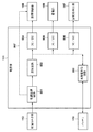
放射線撮影システムは、放射線撮影装置として機能する放射線画像検出器100と、放射線発生装置101と、制御装置102と、曝射スイッチ103と、接続装置104と、中継装置105とを有する。曝射スイッチ103が押下されると、放射線発生装置101は、通信を媒介する接続装置104及び中継装置105を介して、放射線画像検出器100との間で放射線114の照射を行うための信号及び撮影を行うための撮影同期信号を含む制御信号を送受信する。
The radiographic imaging system includes a
放射線発生装置101が生成した放射線114は、被写体113を透過し、放射線画像検出器100へと照射される。放射線画像検出器100は、被写体113を透過する際に減衰した放射線114を、放射線画像として検出する。放射線画像検出器100によって撮影された放射線画像は、中継装置105を介して制御装置102へ出力され、制御装置102により表示器102aに表示される。また、制御装置102は放射線発生装置101とも接続されており、放射線撮影システム全体の制御を行う。
The
放射線画像検出器100と中継装置105との接続には、有線コネクタ112を介した有線による接続と、無線アクセスポイント106を介した無線による接続との少なくとも何れか一方を選択することが可能である。無線による接続の場合、放射線画像検出器100が消費する電力は、放射線画像検出器100内部のバッテリ110によって供給される。
For the connection between the
<放射線画像検出器の構成>
図1に示されるように、放射線画像検出器100は、放射線検出部107と、装置制御部108と、通信部109と、バッテリ110と、電源部111とを有する。バッテリ110は放射線画像検出器100に着脱可能であってもよい。電源部111は、有線コネクタ112が接続されている場合、中継装置105によって商用電源(不図示)から変換された直流電源の電圧を変換し、放射線検出部107と、装置制御部108と、通信部109とへ電力を供給する。また必要に応じて、バッテリ110の充電を行う。なお、クレードルを用いてバッテリ110の充電を行ってもよい。有線コネクタ112が未接続の場合、電源部111は、バッテリ110から供給される電圧を変換し、放射線検出部107と、装置制御部108と、通信部109とへ電力を供給する。
<Structure of radiation image detector>
As shown in FIG. 1, the
放射線検出部107は、照射された放射線114を放射線量に応じた電荷に変換するとともに、装置制御部108の制御下で、当該電荷を、電荷に応じた信号(画像信号)へと変換する。放射線検出部107で得られた画像信号は放射線画像データとして装置制御部108へ出力される。装置制御部108は、オフセット補正機能、ゲイン補正機能、欠損補正機能などの機能を有しており、放射線検出部107から取得した放射線画像データに対して、信号処理/画像処理を行ってもよい。
The
装置制御部108は、放射線画像データを通信部109へと出力し、通信部109は放射線画像データを中継装置105へ出力する。有線コネクタ112が接続されている場合は、有線コネクタ112を介して有線によって放射線画像データを通信し、有線コネクタ112が接続されていない場合は、無線アクセスポイント106を介して無線によって放射線画像データを通信する。
The
なお、図1に示した構成は一例であり、放射線画像検出器100を用いるために接続され得る機器は図示のものに限定されない。また、機器の接続順序も図示のものに限定されない。得られた放射線画像データに対する補正処理についても、その方法は限定されない。システムによっては、放射線画像検出器100への照射許可を必要としなくてもよい。
The configuration shown in FIG. 1 is an example, and the devices that can be connected to use the
<放射線検出部及び装置制御部のハードウェア構成>
続いて、図2を参照して、本実施形態に係る放射線画像検出器100が有する放射線検出部107および装置制御部108のハードウェア構成例を説明する。なお、図2には放射線検出部107および装置制御部108の構成のみを図示している。
<Hardware configuration of radiation detection unit and device control unit>
Subsequently, with reference to FIG. 2, a hardware configuration example of the
放射線検出部107は、信号取得回路202と、ドライブIC203と、光電変換素子204及びスイッチ素子205により構成される複数の画素206とを具備する。画素206の個数は、放射線画像検出器100の画素数に対応する。
The
信号取得回路202(信号処理部)は、信号を増幅するアンプICとアナログ信号をデジタル信号へと変換するADC(Analog Digital Converter)とで構成される。ドライブIC203は、行配線(ライン)を選択して駆動し、その選択された行配線に接続されている画素206のスイッチ素子205をONにする。スイッチ素子205がONになった画素206からは、光電変換素子204に蓄積されている画像信号(電荷)が列配線に出力される。列配線に出力された画像信号は、信号取得回路202により増幅され、デジタルデータへ変換される。ドライブIC203が装置制御部108の制御下で行配線を順次に選択し、信号取得回路202が列配線に出力された画像信号をデジタル化することにより、放射線画像データが得られる。
The signal acquisition circuit 202 (signal processing unit) is composed of an amplifier IC that amplifies the signal and an ADC (Analog Digital Converter) that converts an analog signal into a digital signal. The
また、画素206には放射線を照射せずとも発生する電荷(以下、暗電荷と呼ぶ)も含まれる。暗電荷は放射線照射による信号電荷に重畳されることにより、画像に不均一なアーチファクトを発生させる。撮影された放射線画像データに対して、このようなアーチファクトのオフセット補正処理などの画像処理が行われる。オフセット補正処理には、一般に、放射線を照射しない状態で取得された画像データが補正用データとして用いられる。また、暗電荷は温度によっても大きさが変化しうる。そのため、放射線検出部107の温度の変動は、暗電荷由来のアーチファクトの補正をより困難なものとする。例えば、補正用データを撮影前にあらかじめ取得する場合、撮影中の放射線検出部107の温度の変動により高精度な補正が困難となる。よって、放射線検出部107の温度は可能な限り一定に保つことが望ましい。なお、図2に示した構成は一例であり、これに限定されるものではない。
Further, the
信号取得回路202は、アナログ信号をデジタル信号へと変換して装置制御部108へ当該デジタル信号を送信する一連の動作を行っている場合と、行っていない場合とで消費電力が異なり、発熱量も異なる。
The
装置制御部108は、CPU207と、FPGA208(Field−Programmable Gate Array)と、ROMおよび/またはRAMを含むメモリ209とを具備する。装置制御部108では、CPU207によるメモリ209に格納されたプログラムの実行、FPGA208による処理動作が実現される。
The
<駆動シーケンス>
次に、図3は、動画フレームレートが異なる2つの駆動シーケンスの例を示す。第1の動画フレームレート(フレーム間の時間がT1)におけるシーケンスとして、フレーム301と、撮影同期信号302と、放射線照射303と、センサ駆動状態304と、消費電力305とが示されている。また、第2の動画フレームレート(フレーム間の時間がT1よりも長いT2)におけるシーケンスとして、フレーム306と、撮影同期信号307と、放射線照射308と、センサ駆動状態309と、消費電力310とが示されている。
<Drive sequence>
Next, FIG. 3 shows an example of two drive sequences having different moving image frame rates. As a sequence at the first moving image frame rate (time between frames T1), a
第1の動画フレームレートは、第2の動画フレームレートと比較して、単位時間当たりの読み出し時間が長いため、単位時間当たりの消費電力が大きい。そのため、第1の動画フレームレートと、第2の動画フレームレートとで発熱量が異なり、動画フレームレートの切り替えによって放射線画像検出器100の温度変動が生じる。また、センサ駆動状態304及びセンサ駆動状態309の読み出し時間がそれぞれ異なる駆動モードを放射線画像検出器100が有する場合、駆動モードの切り替えによって放射線画像検出器100に温度変動が生じる。
Since the first moving image frame rate has a longer read time per unit time than the second moving image frame rate, the power consumption per unit time is large. Therefore, the amount of heat generated differs between the first moving image frame rate and the second moving image frame rate, and the temperature fluctuation of the
<温度一定化駆動シーケンス>
これに対して、図4は、本実施形態に係る温度変動を防ぐための駆動を行った場合の、動画フレームレートが異なる2つの駆動シーケンスを示す。第1の動画フレームレート(フレーム間の時間がT1)におけるシーケンスとして、フレーム401と、撮影同期信号402と、放射線照射403と、センサ駆動状態404と、消費電力405とが示されている。また、第2の動画フレームレート(フレーム間の時間がT1よりも長いT2)におけるシーケンスとして、フレーム406と、撮影同期信号407と、放射線照射408と、センサ駆動状態409と、消費電力410とが示されている。
<Temperature constant drive sequence>
On the other hand, FIG. 4 shows two drive sequences having different moving image frame rates when the drive for preventing the temperature fluctuation according to the present embodiment is performed. As a sequence at the first moving image frame rate (time between frames T1), a
図3と異なるのは、電荷蓄積中においても、信号取得回路202にアナログ−デジタル変換、デジタル信号送信を行わせる(以下、温度一定化駆動と呼称する)点である。この際、スイッチ素子205の操作は行わないため、画素206の電荷の蓄積は維持される。電荷蓄積中においても、信号取得回路202を駆動させ、センサ駆動状態404、センサ駆動状態409の違いによる消費電力の変動を抑えることで、信号取得回路202の発熱量を一定に保ち、高精細な画像の作成が可能となる。また、放射線照射がなされていない場合においても、同様の駆動を繰り返すことで、温度変動を抑えた状態での待機が可能となる。
The difference from FIG. 3 is that the
<電源部の構成>
本実施形態では、放射線画像検出器100への電力供給が、有線コネクタ112を通じて外部から行われるか、バッテリ110によって内部で行われるかによって温度一定化駆動の使用を制御する。図5に、本実施形態に係る電源部111の構成例を示す。電源部111は、電源監視回路501と、昇圧回路502と、充放電制御回路503と、DC/DCコンバータ504、505、506とを備える。
<Structure of power supply unit>
In the present embodiment, the use of the temperature constant drive is controlled depending on whether the power supply to the
有線コネクタ112が接続されて外部から電力が放射線検出器100へと供給される場合、電源監視回路501を介して、昇圧回路502において、中継装置105から放射線画像検出器100までのケーブル損失で降圧された電圧を所望の電圧へ昇圧する。昇圧された電圧はDC/DCコンバータ504、505、506にて必要な電圧に変換され、それぞれ、装置制御部108、通信部109、放射線検出部107へと電力が供給される。
When the
また、バッテリ110の充電が十分でない場合は、充放電制御回路503は、バッテリ110の充電を行う。有線コネクタ112が接続されず、外部から放射線検出器100へ電力が供給されない場合、バッテリ110に蓄えられた電力が充放電制御回路503により制御されて、DC/DCコンバータ504、505、506へ電力が供給される。DC/DCコンバータ504、505、506は外部からの電力供給がなされている場合と同様に、それぞれ、装置制御部108、通信部109、放射線検出部107へと電力を供給する。また、電源監視回路501は外部からの電力供給の有無を監視し、外部供給有無信号507を装置制御部108へと送信する。
If the
<装置制御部及び通信部の構成>
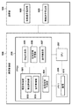
続いて、図6に、本実施形態に係る装置制御部108が有する機能概略と通信部109の構成の一例を示す。装置制御部108の内部のFPGA208は、機能モジュールとして、駆動制御部601と、画像取得制御部604と、画像処理部605と、電源監視受信部606と、通信制御部607とを有する。通信部109は、有線送受信回路608と、無線送受信回路609とを含む。
<Structure of device control unit and communication unit>
Subsequently, FIG. 6 shows an outline of the functions of the
駆動制御部601は、検出制御部602と、温度制御部603とを有する。検出制御部602は、放射線検出部107を駆動させ、放射線画像を取得する。このとき、温度制御部603は、電源監視受信部606で受信した外部供給有無信号507に応じて、温度一定化駆動の切り替えを行う。画像取得制御部604は、取得した放射線画像を画像610としてメモリ209へ記憶する。この際、メモリ209に複数の画像が記憶されてもよい。
The
画像処理部605は、オフセット補正機能、ゲイン補正機能、欠損補正機能などの機能に基づく画像補正処理を行う。電源監視受信部606は、電源監視回路501から外部供給有無信号507を受信する。通信制御部607は、通信部109の動作を制御する。画像処理部605により処理された画像610は、当該通信制御部607により通信部109へ出力される。このとき、通信制御部607は、放射線画像検出器100の使用形態に応じて、有線送受信回路608と、無線送受信回路609とを選択的に制御し、中継装置105へと画像を転送する。
The
<動画シーケンス>
図7は、外部から電力が供給される場合の動画シーケンスと、バッテリから電力が供給される場合の動画シーケンスとを示す。外部から電力が供給される場合の動画シーケンスとして、フレーム701と、撮影同期信号702と、放射線照射703と、センサ駆動状態704と、消費電力705とが示されている。また、バッテリ110から電力が供給される場合の動画駆動シーケンスとして、フレーム706と、撮影同期信号707と、放射線照射708と、センサ駆動状態709と、消費電力710とが示されている。
<Video sequence>
FIG. 7 shows a moving image sequence when power is supplied from the outside and a moving image sequence when power is supplied from the battery. As a moving image sequence when power is supplied from the outside, a frame 701, a
外部から電力が供給される場合は温度一定化駆動を行うことで、温度変動を抑え、より高精細な画像を作成するように制御する。これにより、例えば撮影前にオフセット補正用の画像を取得する場合でも、画質の劣化を抑えることができる。一方、バッテリ110からの電力供給の場合は温度一定化駆動を停止する。これにより、消費電力を小さくし、より長時間の稼働を行うことが可能となる。
When power is supplied from the outside, temperature fluctuation is suppressed by performing temperature constant drive, and control is performed to create a higher-definition image. As a result, deterioration of image quality can be suppressed even when, for example, an image for offset correction is acquired before shooting. On the other hand, in the case of power supply from the
<処理>
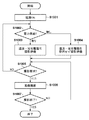
図8は、本実施形態に係る放射線画像検出器100が実施する処理の手順を示すフローチャートである。放射線画像検出器100の電源がONにされる(S801)。装置制御部108は、電源部111の電源監視回路501から出力された外部供給有無信号507を確認し、外部からの電力供給の有無を判定する(S802)。外部から電力が供給されている場合、S803へ進む。一方、外部から電力が供給されていない場合、すなわち、放射線画像検出器100のバッテリ110で動作している場合、S804へ進む。
<Processing>
FIG. 8 is a flowchart showing a procedure of processing performed by the
装置制御部108の駆動制御部601は、放射線画像検出器100を温度一定化駆動で動作させる制御を行う(S803)。装置制御部108の駆動制御部601は、温度一定化駆動を使用せずに放射線画像検出器100を動作させる制御を行う(S804)。
The
以上説明したように、本実施形態では、外部電源から電力が供給されている場合には温度一定化駆動を実施することで、放射線検出部の温度の変動を抑え、画質の劣化を低減させる。一方、外部電源から電力が供給されておらず内部バッテリから電力が供給されている場合には温度一定化駆動を実施しない制御を行うことで、撮影可能時間の減少を防ぐことを優先する。このように、本実施形態では、内部バッテリによる給電が可能な放射線撮影装置において、電源供給の方法に応じて動画撮影時の放射線検出部の駆動制御を変える。これにより、可能な限り画質の劣化を低減しつつ、内部バッテリ給電時の撮影可能時間の減少を防ぐことができるため、ユーザの利便性を向上させることが可能となる。 As described above, in the present embodiment, when the electric power is supplied from the external power source, the temperature constant drive is performed to suppress the temperature fluctuation of the radiation detection unit and reduce the deterioration of the image quality. On the other hand, when the power is not supplied from the external power source and the power is supplied from the internal battery, it is prioritized to prevent the decrease in the shootable time by performing the control not to execute the temperature constant drive. As described above, in the present embodiment, in the radiation photographing apparatus capable of supplying power by the internal battery, the drive control of the radiation detecting unit at the time of moving image is changed according to the method of power supply. As a result, it is possible to reduce the deterioration of the image quality as much as possible and prevent the shooting time from being reduced when the internal battery is supplied, so that the convenience of the user can be improved.
(第2実施形態)
<概要>
第2実施形態では、静止画像取得時において、外部電源から電力が供給される場合には静止画撮影を行わない待機中(撮影待機状態)でも温度一定化駆動を実施し、外部電源から電力が供給されていない場合には、待機中に温度一定化駆動を実施しない制御について説明する。
(Second Embodiment)
<Overview>
In the second embodiment, when a still image is acquired, if power is supplied from an external power source, the temperature constant drive is performed even during standby (shooting standby state) in which still image shooting is not performed, and power is supplied from the external power source. A control in which the temperature constant drive is not performed during standby when the power is not supplied will be described.
<駆動シーケンス>
図9は、本実施形態に係る静止画像取得時の駆動シーケンスである。放射線撮影システムの構成は第1実施形態と同様である。外部から電力が供給される場合の静止画シーケンスとして、撮影要求901と、放射線照射902と、センサ駆動状態903と、消費電力904とが示されている。また、バッテリ110から電力が供給される場合の静止画シーケンスとして、撮影要求905と、放射線照射906と、センサ駆動状態907と、消費電力908とが示されている。
<Drive sequence>
FIG. 9 is a drive sequence at the time of still image acquisition according to the present embodiment. The configuration of the radiography system is the same as that of the first embodiment. As a still image sequence when power is supplied from the outside, a
外部から電力が供給される場合は、センサ駆動状態903に示されるように、第1実施形態の動画シーケンスと同様の温度一定化駆動を待機中においても行うことにより、待機中から撮影に移る際の温度変動を低減することが可能となる。 When power is supplied from the outside, as shown in the sensor drive state 903, by performing the same temperature constant drive as in the moving image sequence of the first embodiment even during standby, when shifting from standby to shooting. It is possible to reduce the temperature fluctuation of.
一方、バッテリ110から電力が供給される場合は、センサ駆動状態907に示されるように、待機中に温度一定化駆動を止めるスタンバイ状態とする。これにより、消費電力を小さくし、温度一定化駆動を続けた場合と比較して長時間の稼働を行うことが可能な駆動へと切り替えることが可能である。
On the other hand, when the electric power is supplied from the
<処理>
図10は、本実施形態に係る放射線画像検出器100が実施する処理の手順を示すフローチャートである。放射線画像検出器100の電源がONにされる(S1001)。装置制御部108は、電源部111の電源監視回路501から出力された外部供給有無信号507を確認し、外部からの電力供給の有無を判定する(S1002)。外部から電力が供給されている場合、S1003へ進む。一方、外部から電力が供給されていない場合、すなわち、放射線画像検出器100のバッテリ110で動作している場合、S1004へ進む。
<Processing>
FIG. 10 is a flowchart showing a procedure of processing performed by the
装置制御部108の駆動制御部601は、放射線画像検出器100を温度一定化駆動で待機させる制御を行う(S1003)。装置制御部108の駆動制御部601は、温度一定化駆動を使用せずに放射線画像検出器100を待機させる制御(スタンバイ状態での待機)を行う(S1004)。
The
続いて、装置制御部108は、通信部109を制御して曝射スイッチ103の押下に応じた撮影要求がなされたか否かを確認する(S1005)。撮影要求がなされた場合、画像を撮影する(S1006)。一方、撮影要求がない場合は、S1002に戻る。撮影後、撮影終了か、継続して撮影が行われるかを確認する(S1007)。撮影終了の場合とは、例えば放射線画像検出器100の電源がOFFにされたり、不図示の撮影終了ボタンが押下されたりした場合であってもよい。継続して撮影が行われる場合はS1005に戻る。
Subsequently, the
以上説明したように、本実施形態では、静止画像取得時において、外部電源から電力が供給されている場合には静止画撮影を行わない待機中でも温度一定化駆動を実施することで、待機中における放射線検出部の温度の変動を抑え、画質の劣化を低減させる。一方、外部電源から電力が供給されておらず内部バッテリから電力が供給されている場合には、待機中に温度一定化駆動を実施しない制御を行うことで、撮影可能時間の減少を防ぐことを優先する。このように、本実施形態では、内部バッテリによる給電が可能な放射線撮影装置において、電源供給の方法に応じて待機中の放射線検出部の駆動制御を変える。これにより、可能な限り画質の劣化を低減しつつ、内部バッテリ給電時の撮影可能時間の減少を防ぐことができるため、ユーザの利便性を向上させることが可能となる。 As described above, in the present embodiment, when the still image is acquired, when the power is supplied from the external power source, the temperature constant drive is performed even during the standby without taking the still image, so that the still image is in the standby state. It suppresses temperature fluctuations in the radiation detector and reduces deterioration of image quality. On the other hand, when power is not supplied from the external power supply and power is supplied from the internal battery, it is possible to prevent a decrease in the shootable time by performing control that does not perform constant temperature drive during standby. Prioritize. As described above, in the present embodiment, in the radiography apparatus capable of supplying power by the internal battery, the drive control of the standby radiation detection unit is changed according to the power supply method. As a result, it is possible to reduce the deterioration of the image quality as much as possible and prevent the shooting time from being reduced when the internal battery is supplied, so that the convenience of the user can be improved.
(第3実施形態)
<概要>
第3実施形態では、放射線検出部の温度を監視し、当該温度変化(温度勾配)に応じて温度一定化駆動を実施する時間的な割合を変更する制御について説明する。
(Third Embodiment)
<Overview>
In the third embodiment, the control of monitoring the temperature of the radiation detection unit and changing the temporal ratio of performing the temperature constant drive according to the temperature change (temperature gradient) will be described.
<構成>
図11は、本実施形態に係る放射線画像検出器の構成例を示す。放射線撮影システムの構成は第1実施形態と同様である。但し、本実施形態に係る放射線画像検出器100は、図1の構成に加えて、放射線検出部107の温度を検出する温度センサ1101をさらに備えている。また、本実施形態に係る装置制御部108が備える温度制御部603は、電源監視受信部606で受信した外部供給有無信号507に応じて温度一定化駆動の切り替えを行う。さらに、温度センサ1001による検出結果である放射線検出部107の温度の変化を監視する。そして、装置制御部108は、放射線検出部107の温度の変化に基づいて温度一定化駆動の切り替えをさらに制御する。
<Composition>
FIG. 11 shows a configuration example of the radiographic image detector according to the present embodiment. The configuration of the radiography system is the same as that of the first embodiment. However, the
<動画シーケンス>
図12は、本実施形態に係る動画シーケンスの一例を示す。温度センサ1101により放射線検出部107の温度を監視し、温度勾配に応じて、温度一定化駆動の実施割合を変更する。温度が低下する場合には、消費電力を増やすため、温度一定化駆動の実施割合を増やす。反対に、温度が上昇する場合には、消費電力を減らすため、温度一定化駆動の実施割合を減少させる。
<Video sequence>
FIG. 12 shows an example of a moving image sequence according to the present embodiment. The temperature of the
具体的には、図13に示されるように、温度勾配(T2−T1)/(t2−t1)の値を算出する。図示の例では当該値は正の値である。すなわち、放射線画像検出器100の駆動によって放射線検出部107の温度が上昇しているため、t2−t1の期間において温度一定化駆動の実施割合を減少させる。一方、温度勾配(T2−T3)/(tn−tn+1)の値を算出すると、図示の例では当該値は負の値である。すなわち、放射線検出部107の温度が下降しているため、tn−tn+1の期間において温度一定化駆動の実施割合を増やす。
Specifically, as shown in FIG. 13, the value of the temperature gradient (T2-T1) / (t2-t1) is calculated. In the illustrated example, the value is a positive value. That is, since the temperature of the
さらに、温度勾配の数値の大きさに応じて、温度一定化駆動の実施割合を調整してもよい。例えば、温度勾配が正の値で且つ大きいほど温度一定化駆動の実施割合を減らし、温度勾配が負の値で且つその絶対値が大きいほど温度一定化駆動の実施割合を増やすように制御してもよい。 Further, the execution rate of the temperature constant drive may be adjusted according to the magnitude of the numerical value of the temperature gradient. For example, the more the temperature gradient is positive and the larger the temperature gradient is, the less the temperature constant drive is executed, and the more the temperature gradient is negative and the larger the absolute value is, the more the temperature constant drive is executed. May be good.
以上説明したように、本実施形態では、放射線検出部の温度を監視し、当該温度変化(温度勾配)に応じて温度一定化駆動を実施する時間的な割合を変更する制御を行う。これにより、放射線検出部の温度を一定に保持することが可能になり、画質の劣化を低減することが可能となる。 As described above, in the present embodiment, the temperature of the radiation detection unit is monitored, and control is performed to change the temporal ratio of performing the temperature constant drive according to the temperature change (temperature gradient). As a result, the temperature of the radiation detection unit can be kept constant, and deterioration of image quality can be reduced.
(第4実施形態)
<概要>
第4実施形態では、外部電源によるバッテリ充電を行いながら温度一定化駆動を実施する場合に、バッテリ充電に起因した消費電力の増加分による温度上昇を考慮して温度一定化駆動の実施割合を調整する制御について説明する。
(Fourth Embodiment)
<Overview>
In the fourth embodiment, when the temperature constant drive is performed while charging the battery with an external power source, the temperature constant drive implementation ratio is adjusted in consideration of the temperature rise due to the increase in power consumption due to the battery charge. The control to be performed will be described.
<動画シーケンス>
図14は、本実施形態に係る動画シーケンスの一例を示す。放射線撮影システムの構成、放射線画像検出器100の構成は第3実施形態と同様である。1401は、外部電源からの電力供給がある場合の動画駆動に関するセンサ状態と消費電力との関係を示す。1402は、外部電源からの電力供給があり、バッテリ充電と動画駆動とを行う場合に関するセンサ状態と消費電力との関係を示す。1403は、本実施形態に係るバッテリ充電駆動におけるセンサ状態と消費電力との関係を示す。1402に示されるように、外部電源から供給される電力によりバッテリ充電を行う場合、充電に応じた消費電力の分だけ全体の消費電力が増加し、ひいては温度上昇につながる。そこで、本実施形態では、1403に示されるように、充電に応じて増加した消費電力の分を削減すべく、温度一定化駆動の実施割合を減少させる。
<Video sequence>
FIG. 14 shows an example of a moving image sequence according to the present embodiment. The configuration of the radiographic imaging system and the configuration of the
これにより、撮影中と、バッテリ充電を伴う暖機運転中とで、発生する熱を揃えることが可能となり、温度変化を抑制し、画質の劣化を低減することが可能となる。 As a result, it is possible to align the generated heat during shooting and during warm-up operation accompanied by battery charging, and it is possible to suppress temperature changes and reduce deterioration of image quality.
(その他の実施形態)
本発明は、上述の実施形態の1以上の機能を実現するプログラムを、ネットワーク又は記憶媒体を介してシステム又は装置に供給し、そのシステム又は装置のコンピュータにおける1つ以上のプロセッサがプログラムを読出し実行する処理でも実現可能である。また、1以上の機能を実現する回路(例えば、ASIC)によっても実現可能である。
(Other embodiments)
The present invention supplies a program that realizes one or more functions of the above-described embodiment to a system or device via a network or storage medium, and one or more processors in the computer of the system or device reads and executes the program. It can also be realized by the processing to be performed. It can also be realized by a circuit (for example, ASIC) that realizes one or more functions.
100:放射線画像検出器、101:放射線発生装置、102:制御装置、103:曝射スイッチ、104:接続装置、105:中継装置、106:無線アクセスポイント、107:放射線検出部、108:装置制御部、109:通信部、110:バッテリ、111:電源部、112:有線コネクタ、113:被写体、114:放射線、202:信号取得回路、203:ドライブIC、204:光電変換素子、205:スイッチ素子、206:画素、207:CPU、208:FPGA、209:メモリ、501:電源監視回路、502:昇圧回路、503:充放電制御回路、504:DC/DCコンバータ、505:DC/DCコンバータ、506:DC/DCコンバータ、507:外部供給有無信号、601:駆動制御部、602:検出制御部、603:温度制御部、604:画像取得制御部、605:画像処理部、606:電源監視受信部、607:通信制御部、608:有線送受信回路、609:無線送受信回路、1101:温度センサ 100: Radiation image detector, 101: Radiation generator, 102: Control device, 103: Exposure switch, 104: Connection device, 105: Relay device, 106: Wireless access point, 107: Radiation detector, 108: Device control Unit, 109: Communication unit, 110: Battery, 111: Power supply unit, 112: Wired connector, 113: Subject, 114: Radiation, 202: Signal acquisition circuit, 203: Drive IC, 204: Photoelectric conversion element, 205: Switch element , 206: Pixel, 207: CPU, 208: FPGA, 209: Memory, 501: Power supply monitoring circuit, 502: Booster circuit, 503: Charge / discharge control circuit, 504: DC / DC converter, 505: DC / DC converter, 506 : DC / DC converter, 507: External supply presence / absence signal, 601: Drive control unit, 602: Detection control unit, 603: Temperature control unit, 604: Image acquisition control unit, 605: Image processing unit, 606: Power supply monitoring / reception unit , 607: Communication control unit, 608: Wired transmission / reception circuit, 609: Wireless transmission / reception circuit, 1101: Temperature sensor
Claims (14)
外部電源からの電力供給の有無を判定する判定手段と、
前記放射線検出部の駆動を制御する制御手段と、を有し、
前記制御手段は、前記外部電源からの電力供給がある場合に、前記放射線撮影装置の温度を保持するための駆動を実施する第1のモードで前記放射線検出部の駆動を制御し、前記外部電源から電力が供給されておらず前記バッテリから電力が供給されている場合に、前記温度を保持するための駆動を実施しない第2のモードで前記放射線検出部の駆動を制御することを特徴とする放射線撮影装置。 It is a radiography device that has a radiation detector that converts the radiation that has passed through the subject into electric charges and can supply power from a battery.
Judgment means for determining the presence or absence of power supply from an external power source,
It has a control means for controlling the drive of the radiation detection unit, and has.
Wherein, when there is power supply from the external power source, the driving of the radiation detection section is controlled in the first mode of implementing the driving movement for maintaining the temperature of the radiation imaging apparatus, the external When power is not supplied from the power source and power is supplied from the battery, the drive of the radiation detection unit is controlled in a second mode in which the drive for maintaining the temperature is not performed. Radiation imaging device.
当該デジタル信号を前記放射線検出部の外へ送信する動作を行う信号処理部を有し、
前記制御手段は、前記放射線検出部の電荷蓄積中において、前記信号処理部に前記動作を行わせることで、前記温度を保持するための駆動を実施することを特徴とする請求項1に記載の放射線撮影装置。 The radiation detection unit converts an analog signal based on the accumulated charge into a digital signal, and then converts it into a digital signal.
It has a signal processing unit that performs an operation of transmitting the digital signal to the outside of the radiation detection unit.
The first aspect of the present invention, wherein the control means drives the signal processing unit to maintain the temperature while the radiation detection unit is accumulating charges. Radiation imaging device.
前記制御手段は、前記温度センサの検出結果に基づいて、前記温度を保持するための駆動の実施を制御することを特徴とする請求項1乃至4のいずれか1項に記載の放射線撮影装置。 Further equipped with a temperature sensor for detecting the temperature of the radiography apparatus,
The radiography apparatus according to any one of claims 1 to 4, wherein the control means controls the execution of driving for maintaining the temperature based on the detection result of the temperature sensor.
前記放射線撮影装置へ照射する放射線を発生させる放射線発生装置と、
前記放射線撮影装置と放射線発生装置とを制御する制御装置と、
を備えることを特徴とする放射線撮影システム。 The radiography apparatus according to any one of claims 1 to 11.
A radiation generator that generates radiation to irradiate the radiographer,
A control device that controls the radiography device and the radiation generator,
A radiography system characterized by being equipped with.
外部電源からの電力供給の有無を判定する判定工程と、
前記外部電源からの電力供給がある場合に、前記放射線撮影装置の温度を保持するための駆動を実施する第1のモードで前記放射線撮影装置の駆動を制御する第1の制御工程と、
前記外部電源から電力が供給されておらず前記バッテリから電力が供給されている場合に、前記温度を保持するための駆動を実施しない第2のモードで前記放射線検出部の駆動を制御する第2の制御工程と、
を有することを特徴とする放射線撮影装置の制御方法。 It is a control method of a radiography device that has a radiation detector that converts the radiation that has passed through the subject into electric charges and can supply power from a battery.
Judgment process to determine the presence or absence of power supply from an external power source,
If there is power supply from the external power source, a first control step of controlling the driving of the radiation imaging device in the first mode of implementing the driving movement for maintaining the temperature of the radiation imaging apparatus,
A second mode for controlling the drive of the radiation detection unit in a second mode in which the drive for maintaining the temperature is not performed when the power is not supplied from the external power source and the power is supplied from the battery. Control process and
A method for controlling a radiography apparatus, which comprises.
Priority Applications (1)
| Application Number | Priority Date | Filing Date | Title |
|---|---|---|---|
| JP2016234422A JP6800720B2 (en) | 2016-12-01 | 2016-12-01 | Radiation imaging equipment, radiography imaging system, radiography equipment control methods and programs |
Applications Claiming Priority (1)
| Application Number | Priority Date | Filing Date | Title |
|---|---|---|---|
| JP2016234422A JP6800720B2 (en) | 2016-12-01 | 2016-12-01 | Radiation imaging equipment, radiography imaging system, radiography equipment control methods and programs |
Publications (3)
| Publication Number | Publication Date |
|---|---|
| JP2018091689A JP2018091689A (en) | 2018-06-14 |
| JP2018091689A5 JP2018091689A5 (en) | 2020-01-09 |
| JP6800720B2 true JP6800720B2 (en) | 2020-12-16 |
Family
ID=62563724
Family Applications (1)
| Application Number | Title | Priority Date | Filing Date |
|---|---|---|---|
| JP2016234422A Active JP6800720B2 (en) | 2016-12-01 | 2016-12-01 | Radiation imaging equipment, radiography imaging system, radiography equipment control methods and programs |
Country Status (1)
| Country | Link |
|---|---|
| JP (1) | JP6800720B2 (en) |
Families Citing this family (2)
| Publication number | Priority date | Publication date | Assignee | Title |
|---|---|---|---|---|
| CN110488339B (en) * | 2019-09-04 | 2021-03-19 | 绵阳市维博电子有限责任公司 | Gamma radiation detection circuit with diagnosis function and diagnosis method |
| JP7390845B2 (en) | 2019-10-07 | 2023-12-04 | キヤノン株式会社 | radiography equipment |
-
2016
- 2016-12-01 JP JP2016234422A patent/JP6800720B2/en active Active
Also Published As
| Publication number | Publication date |
|---|---|
| JP2018091689A (en) | 2018-06-14 |
Similar Documents
| Publication | Publication Date | Title |
|---|---|---|
| US10009990B2 (en) | Imaging apparatus, control method therefor, and imaging system | |
| JP3950665B2 (en) | Radiation imaging apparatus and imaging method of radiation imaging apparatus | |
| US9001972B2 (en) | Radiation image detection apparatus and radiation image photographing system | |
| US10498975B2 (en) | Radiation imaging apparatus, method of controlling the same, and radiation imaging system | |
| JP6800720B2 (en) | Radiation imaging equipment, radiography imaging system, radiography equipment control methods and programs | |
| JP6917752B2 (en) | Radiation imaging device and its control method, program | |
| US11079341B2 (en) | Radiation imaging apparatus, control apparatus, and control methods and storage mediums therefor | |
| US9031190B2 (en) | X-ray imaging apparatus | |
| US20140254765A1 (en) | Display control apparatus, display control method, and computer-readable storage medium storing program | |
| JP2019154785A (en) | Radiographic apparatus and control method therefor, program, and radiographic system | |
| US11128816B2 (en) | Radiographic imaging system | |
| JP6164877B2 (en) | Control device, radiation imaging apparatus, radiation imaging system, control method and program for radiation imaging apparatus | |
| US9894306B2 (en) | Radiation imaging system, control apparatus, control method, and storage medium | |
| JP6577762B2 (en) | Radiation imaging apparatus, radiation imaging system, and program | |
| JP2018175080A (en) | Radiographic apparatus, radiographic system, and control method and program of radiographic apparatus | |
| JP6419265B2 (en) | Image processing apparatus, control method, and program | |
| JP6821351B2 (en) | Radiation imaging device, radiation imaging system, control method of radiation imaging device | |
| JP2011117930A (en) | Radiation image forming device and radiation image forming method | |
| JP6700882B2 (en) | Radiation imaging apparatus, control method thereof, radiation imaging system and program | |
| JP5592705B2 (en) | Calibration data storage system | |
| JP6853644B2 (en) | Radiation imaging device, radiation imaging system, radiation imaging method and program | |
| JP2020048864A (en) | Imaging control apparatus, radiation imaging apparatus, and radiation imaging system | |
| JP2022123631A (en) | Radiation imaging apparatus, radiation imaging system, and control method and program of radiation imaging apparatus | |
| US20240138799A1 (en) | Radiographic imaging apparatus, radiographic imaging system, and method for controlling radiographic imaging apparatus | |
| JP7087435B2 (en) | Radiation imaging device and radiation imaging system |
Legal Events
| Date | Code | Title | Description |
|---|---|---|---|
| A521 | Request for written amendment filed |
Free format text: JAPANESE INTERMEDIATE CODE: A523 Effective date: 20191115 |
|
| A621 | Written request for application examination |
Free format text: JAPANESE INTERMEDIATE CODE: A621 Effective date: 20191115 |
|
| A977 | Report on retrieval |
Free format text: JAPANESE INTERMEDIATE CODE: A971007 Effective date: 20201015 |
|
| TRDD | Decision of grant or rejection written | ||
| A01 | Written decision to grant a patent or to grant a registration (utility model) |
Free format text: JAPANESE INTERMEDIATE CODE: A01 Effective date: 20201026 |
|
| A61 | First payment of annual fees (during grant procedure) |
Free format text: JAPANESE INTERMEDIATE CODE: A61 Effective date: 20201125 |
|
| R151 | Written notification of patent or utility model registration |
Ref document number: 6800720 Country of ref document: JP Free format text: JAPANESE INTERMEDIATE CODE: R151 |