JP6800613B2 - Liquid discharge device and liquid discharge head - Google Patents
Liquid discharge device and liquid discharge head Download PDFInfo
- Publication number
- JP6800613B2 JP6800613B2 JP2016107296A JP2016107296A JP6800613B2 JP 6800613 B2 JP6800613 B2 JP 6800613B2 JP 2016107296 A JP2016107296 A JP 2016107296A JP 2016107296 A JP2016107296 A JP 2016107296A JP 6800613 B2 JP6800613 B2 JP 6800613B2
- Authority
- JP
- Japan
- Prior art keywords
- liquid
- flow path
- discharge
- head
- liquid discharge
- Prior art date
- Legal status (The legal status is an assumption and is not a legal conclusion. Google has not performed a legal analysis and makes no representation as to the accuracy of the status listed.)
- Active
Links
Images


Classifications
-
- B—PERFORMING OPERATIONS; TRANSPORTING
- B41—PRINTING; LINING MACHINES; TYPEWRITERS; STAMPS
- B41J—TYPEWRITERS; SELECTIVE PRINTING MECHANISMS, i.e. MECHANISMS PRINTING OTHERWISE THAN FROM A FORME; CORRECTION OF TYPOGRAPHICAL ERRORS
- B41J2/00—Typewriters or selective printing mechanisms characterised by the printing or marking process for which they are designed
- B41J2/005—Typewriters or selective printing mechanisms characterised by the printing or marking process for which they are designed characterised by bringing liquid or particles selectively into contact with a printing material
- B41J2/01—Ink jet
- B41J2/17—Ink jet characterised by ink handling
- B41J2/175—Ink supply systems ; Circuit parts therefor
- B41J2/17503—Ink cartridges
- B41J2/17553—Outer structure
-
- B—PERFORMING OPERATIONS; TRANSPORTING
- B41—PRINTING; LINING MACHINES; TYPEWRITERS; STAMPS
- B41J—TYPEWRITERS; SELECTIVE PRINTING MECHANISMS, i.e. MECHANISMS PRINTING OTHERWISE THAN FROM A FORME; CORRECTION OF TYPOGRAPHICAL ERRORS
- B41J2/00—Typewriters or selective printing mechanisms characterised by the printing or marking process for which they are designed
- B41J2/005—Typewriters or selective printing mechanisms characterised by the printing or marking process for which they are designed characterised by bringing liquid or particles selectively into contact with a printing material
- B41J2/01—Ink jet
- B41J2/015—Ink jet characterised by the jet generation process
- B41J2/04—Ink jet characterised by the jet generation process generating single droplets or particles on demand
- B41J2/045—Ink jet characterised by the jet generation process generating single droplets or particles on demand by pressure, e.g. electromechanical transducers
-
- B—PERFORMING OPERATIONS; TRANSPORTING
- B41—PRINTING; LINING MACHINES; TYPEWRITERS; STAMPS
- B41J—TYPEWRITERS; SELECTIVE PRINTING MECHANISMS, i.e. MECHANISMS PRINTING OTHERWISE THAN FROM A FORME; CORRECTION OF TYPOGRAPHICAL ERRORS
- B41J2/00—Typewriters or selective printing mechanisms characterised by the printing or marking process for which they are designed
- B41J2/005—Typewriters or selective printing mechanisms characterised by the printing or marking process for which they are designed characterised by bringing liquid or particles selectively into contact with a printing material
- B41J2/01—Ink jet
- B41J2/135—Nozzles
- B41J2/14—Structure thereof only for on-demand ink jet heads
- B41J2/14016—Structure of bubble jet print heads
- B41J2/14032—Structure of the pressure chamber
-
- B—PERFORMING OPERATIONS; TRANSPORTING
- B41—PRINTING; LINING MACHINES; TYPEWRITERS; STAMPS
- B41J—TYPEWRITERS; SELECTIVE PRINTING MECHANISMS, i.e. MECHANISMS PRINTING OTHERWISE THAN FROM A FORME; CORRECTION OF TYPOGRAPHICAL ERRORS
- B41J2/00—Typewriters or selective printing mechanisms characterised by the printing or marking process for which they are designed
- B41J2/005—Typewriters or selective printing mechanisms characterised by the printing or marking process for which they are designed characterised by bringing liquid or particles selectively into contact with a printing material
- B41J2/01—Ink jet
- B41J2/135—Nozzles
- B41J2/145—Arrangement thereof
-
- B—PERFORMING OPERATIONS; TRANSPORTING
- B41—PRINTING; LINING MACHINES; TYPEWRITERS; STAMPS
- B41J—TYPEWRITERS; SELECTIVE PRINTING MECHANISMS, i.e. MECHANISMS PRINTING OTHERWISE THAN FROM A FORME; CORRECTION OF TYPOGRAPHICAL ERRORS
- B41J2/00—Typewriters or selective printing mechanisms characterised by the printing or marking process for which they are designed
- B41J2/005—Typewriters or selective printing mechanisms characterised by the printing or marking process for which they are designed characterised by bringing liquid or particles selectively into contact with a printing material
- B41J2/01—Ink jet
- B41J2/17—Ink jet characterised by ink handling
- B41J2/175—Ink supply systems ; Circuit parts therefor
- B41J2/17596—Ink pumps, ink valves
-
- B—PERFORMING OPERATIONS; TRANSPORTING
- B41—PRINTING; LINING MACHINES; TYPEWRITERS; STAMPS
- B41J—TYPEWRITERS; SELECTIVE PRINTING MECHANISMS, i.e. MECHANISMS PRINTING OTHERWISE THAN FROM A FORME; CORRECTION OF TYPOGRAPHICAL ERRORS
- B41J2/00—Typewriters or selective printing mechanisms characterised by the printing or marking process for which they are designed
- B41J2/005—Typewriters or selective printing mechanisms characterised by the printing or marking process for which they are designed characterised by bringing liquid or particles selectively into contact with a printing material
- B41J2/01—Ink jet
- B41J2/17—Ink jet characterised by ink handling
- B41J2/18—Ink recirculation systems
Description
本発明は、液体吐出ヘッドの吐出口から液体を噴射することによって記録を行う液体吐出装置および液体吐出ヘッドに関する。 The present invention relates to a liquid discharge device and a liquid discharge head that perform recording by injecting a liquid from a discharge port of the liquid discharge head.
インクなどの液体を吐出して記録を行う液体吐出装置では、吐出口におけるメニスカスの位置が変動した場合、以下の問題が生じることが知られている。
1)吐出口から吐出される液滴の量が変化する結果、形成される画像に色むらが発生する。
2)記録媒体と吐出口との相対移動速度に対し、吐出口から吐出される液滴の速度(吐出速度)が変化するため、記録媒体上に着弾する液滴の着弾精度にばらつきが生じ、画像品質が劣化する。
It is known that in a liquid ejection device that ejects a liquid such as ink for recording, the following problems occur when the position of the meniscus in the ejection port fluctuates.
1) As a result of changing the amount of droplets ejected from the ejection port, color unevenness occurs in the formed image.
2) Since the speed (discharge speed) of the droplets discharged from the discharge port changes with respect to the relative movement speed between the recording medium and the discharge port, the landing accuracy of the droplets landing on the recording medium varies. Image quality deteriorates.
これらの問題が発生する原因の1つとして、液体供給流路における動圧(圧力損失)の変動が挙げられる。例えば、ポンプ等の送液機構で液体を供給した場合、一般的に脈動が発生するため、液体の動圧が変動し、吐出口におけるメニスカスの位置が変動し、上記1)、2)のような問題が生じ易い。 One of the causes of these problems is fluctuation of dynamic pressure (pressure loss) in the liquid supply flow path. For example, when a liquid is supplied by a liquid feeding mechanism such as a pump, pulsation generally occurs, so that the dynamic pressure of the liquid fluctuates and the position of the meniscus at the discharge port fluctuates, as in 1) and 2) above. Problems are likely to occur.
特許文献1には、液体供給流路における動圧の変動を抑制することを目的とした技術が開示されている。特許文献1では、液体吐出ヘッドに対して液体を供給する供給路にバルブを設け、このバルブを圧力室内の負圧に基づいて供給路を開放または閉塞することにより、負圧の変動を抑制する構成を採る。
しかしながら、特許文献1に開示の技術では、バルブを作動させるために複雑な構造を必要とし、コスト高になるという課題がある。
However, the technique disclosed in
本発明は、送液手段によって流路内の液体に生じた圧力変動を抑制することができ、吐出口から安定した液体の吐出を行うことが可能な液体吐出装置および液体吐出ヘッドの提供を目的とする。 An object of the present invention is to provide a liquid discharge device and a liquid discharge head capable of suppressing pressure fluctuations generated in a liquid in a flow path by a liquid feeding means and stably discharging a liquid from a discharge port. And.
本発明は、液体を吐出する吐出口を有する液体吐出ヘッドと、前記吐出口に連通する流路と、前記流路へ液体を供給する送液手段と、を備え、前記送液手段から送液される液体の角振動数ω[rad/s]と、前記液体の動粘性係数ν[m 2 /s]と、流路の少なくとも一部の等価直径a[m]と、の関係が、√(ω/2ν)×a>1を満足することを特徴とする。 The present invention includes a liquid discharge head having a discharge port for discharging a liquid, a flow path communicating with the discharge port, and a liquid feeding means for supplying the liquid to the flow path, and the liquid is fed from the liquid feeding means. The relationship between the angular frequency ω [rad / s] of the liquid to be formed, the kinematic viscosity coefficient ν [m 2 / s] of the liquid, and the equivalent diameter a [m] of at least a part of the flow path is √. It is characterized in that (ω / 2ν) × a> 1 is satisfied.
本発明によれば、送液手段によって流路内の液体に生じた圧力変動を抑制することができ、吐出口から安定した液体の吐出を行うことが可能な液体吐出装置および液体吐出ヘッドを提供することができる。 According to the present invention, there is provided a liquid discharge device and a liquid discharge head capable of suppressing pressure fluctuations generated in a liquid in a flow path by a liquid feeding means and stably discharging a liquid from a discharge port. can do.
以下、図面を参照して本発明の実施形態に関わる液体吐出装置について説明する。なお、インク等の液体を吐出する本発明の液体吐出ヘッドおよび液体吐出ヘッドを搭載した液体吐出装置は、プリンタ、複写機、通信システムを有するファクシミリ、プリンタ部を有するワードプロセッサなどの装置、さらには各種処理装置と複合的に組み合わせた産業記録装置に適用可能である。例えば、バイオチップ作製や電子回路印刷や半導体基板作製などの用途としても用いることができる。なお、以下に述べる実施形態は、技術的に好ましい種々の条件が付けられているが、本発明の思想に沿うものであれば、本発明はこれら種々の条件に限定されるものではない。 Hereinafter, the liquid discharge device according to the embodiment of the present invention will be described with reference to the drawings. The liquid discharge head of the present invention for discharging liquid such as ink and the liquid discharge device equipped with the liquid discharge head include a printer, a copying machine, a facsimile having a communication system, a word processor having a printer unit, and various other devices. It is applicable to industrial recording equipment combined with processing equipment. For example, it can also be used for biochip manufacturing, electronic circuit printing, semiconductor substrate manufacturing, and the like. Although various technically preferable conditions are attached to the embodiments described below, the present invention is not limited to these various conditions as long as they are in line with the idea of the present invention.
(第1実施形態)
図1ないし7は、本発明に係る液体吐出装置の第1実施形態を示す図である。なお、本実施形態では、液体吐出装置として、インクを記録媒体に吐出して画像を形成するインクジェット記録装置(以下、単に記録装置という)である。ここで、インクとは、記録媒体に画像を形成するための色材を含んだ液体だけでなく、記録媒体上に形成される画像の定着性、耐候性などを向上させるための処理液などを含むものとする。
(First Embodiment)
1 to 7 are diagrams showing a first embodiment of the liquid discharge device according to the present invention. In the present embodiment, the liquid ejection device is an inkjet recording apparatus (hereinafter, simply referred to as a recording apparatus) that ejects ink onto a recording medium to form an image. Here, the ink is not only a liquid containing a coloring material for forming an image on a recording medium, but also a treatment liquid for improving the fixability, weather resistance, etc. of an image formed on the recording medium. It shall include.
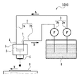
図1は、本実施形態における記録装置1000の基本構成を示す模式図である。記録装置1000は、インクを吐出する液体吐出ヘッド1と、液体吐出ヘッド1へ供給すべきインクを収容する収容体8を備える。さらに、記録装置1000は、液体収容体8と液体吐出ヘッド1とを連結するヘッド外流路2および、ヘッド外流路2においてインクを流動させるための送液手段3を備える。
FIG. 1 is a schematic diagram showing a basic configuration of a
本実施形態におけるヘッド外流路2は、液体収容体(液体供給源)8から液体吐出ヘッド1へと液体を流動させるための上流側流路2aと、液体吐出ヘッド1から液体収容体8へと液体を流動させるための下流側流路2bとを備える。また、本実施形態における送液手段3は、上流側流路2aに接続されたポンプ3aと、下流側流路2bに接続されたポンプ3bとを含む。以下、2つのポンプ3a、3bを特に区別する必要がない場合には、両ポンプを総称してポンプ3と記すこともある。
The head
図2は、本実施形態に用いる液体吐出ヘッド1を示す斜視図であり、(a)は斜視図、(b)は(a)のIIB−IIB´線断面図、(c)は(a)のIIC−IIC´線断面図、(d)は(c)のD部拡大図である。図2(a)に示すように、複数の吐出口60(図2(d)参照)を配列してなる吐出口列61が複数(図2(a)では4本)配列された記録素子基板6と、流路形成部材としての流路プレート5とを備える。流路プレート5には、図2(a)、(b)に示すように、インクが矢印F1方向に流動する共通流路51と、図2(c)に示すように、共通流路51と複数の吐出口列61とを個別に連通させる複数(図2(c)では4本)の個別流路52が形成されている。また、共通流路51の一端部は前述の上流側流路2aに連通し、他端部は前述の下流側流路2bに連通している。なお、流路プレート5に形成される共通流路51と個別流路52とを総称してプレート内流路50ともいう。
2A and 2B are perspective views showing a
図2(d)に示すように、記録素子基板6は、インクを吐出する複数の吐出口60が形成された吐出口形成部材12と、吐出口60からインクを吐出させるための吐出エネルギー発生素子(以下、記録素子という)11が形成されたヒータボード10を有する。記録素子としては、電気熱変換素子(ヒータ)や電気機械変換素子(ピエゾ)などが適用可能であるが、本実施形態では、ヒータを用いている。また、記録素子基板6には、記録素子11と吐出口60とが対向する領域に圧力室62が形成され、さらに圧力室62には、素子基板内流路63を介して、流路プレート5に形成された個別流路52に連通している。なお、プレート内流路50と、素子基板内流路63とにより、ヘッド内流路100が構成されている。
As shown in FIG. 2D, the
以上のように、本実施形態における記録装置1000には、液体吐出ヘッド1の吐出口60へとインクを供給するための流路として、液体吐出ヘッド1外に形成されるヘッド外流路2と、液体吐出ヘッド1内に形成されるヘッド内流路100とが構成されている。
As described above, the
また、記録装置1000は、記録媒体Sを液体吐出ヘッド1に対して相対的に移動させる搬送機構を備える。本実施形態では、記録媒体Sの搬送方向(Y方向)と直交する方向(図1中、紙面と直交する方向)に液体吐出ヘッド1を移動させつつインク滴drを吐出させることにより記録媒体Sに記録を行うシリアル型の記録装置となっている。但し、本発明は、シリアル型の記録装置に限らず、記録媒体を連続的に送りつつ、記録媒体の幅以上の範囲に吐出口を配列した長尺な液体吐出ヘッドを用いて記録を行うフルライン型の記録装置にも適用可能である。
Further, the
上記構成において、ポンプ3a、3bを駆動することにより、液体収容体8に貯留されているインクは、上流側供給流路2aを介して液体吐出ヘッド1の流路プレート5aに形成された共通流路5aに送られる。共通流路5aに流入したインクは、その一部が個別流路52を経て素子基板内流路63に供給される。素子基板内流路63に供給されたインクはさらに圧力室62および吐出口60に供給される。これにより吐出口60にはメニスカスが形成される。また、共通流路51における残りのインクは下流側流路2bおよびポンプ3bを経て液体収容体8に回収される。
In the above configuration, by driving the
記録動作時には、記録素子としてのヒータを駆動し、圧力室内のインクを加熱して圧力室62内に気泡を発生させる。この気泡発生時の圧力によって、メニスカスが形成されている吐出口60からは滴状のインクが吐出される。
During the recording operation, the heater as a recording element is driven to heat the ink in the pressure chamber to generate bubbles in the
ところで、記録装置1000におけるヘッド外流路2およびヘッド内流路100を流れるインクには、流路の内面との摩擦抵抗などによって圧力損失が生じる。
By the way, pressure loss occurs in the ink flowing through the head
一般的に、流路内に流れる流体の圧力損失は流路抵抗とインク流量の関係より以下の式で示される。
ΔP=R×Q ・・・(式1)
ΔP:圧力損失
R:流路抵抗
Q:インク流量
ここで、流路抵抗Rは管路(流路)の定常流れとして導かれるポアゾイユ流れから導出される以下の式が一般的に用いられる。
Generally, the pressure loss of the fluid flowing in the flow path is expressed by the following equation from the relationship between the flow path resistance and the ink flow rate.
ΔP = R × Q ・ ・ ・ (Equation 1)
ΔP: Pressure loss R: Flow path resistance Q: Ink flow rate Here, the flow path resistance R is generally derived from the Poazoille flow derived as a steady flow of a pipeline (flow path).
R=128×η×L/(π×a^4) ・・・(式2)
η:インク粘度
L:管路の長さ
a:管路の等価直径
しかし、図1で示すようにポンプ3a、3bから送出された液体は周期的に圧力が変動する脈動流となることが知られている。この脈動流は、一定の圧力の下で形成されるポアゾイユ流れではなく、管内非定常流れ(調和振動流)となる。特に、一様断面の円管路内の流体に生じる非定常な流速分布は、以下に示す指標の大きさに応じて異なることが知られている。
R = 128 × η × L / (π × a ^ 4) ・ ・ ・ (Equation 2)
η: Ink viscosity L: Length of pipe line a: Equivalent diameter of pipe line However, as shown in FIG. 1, it is known that the liquid sent from the
指標:√(ω/2ν)×a・・・(式3)
ω:脈動の角振動数
ν:インク動粘性係数
a:管路の等価直径
図3は、指標√(ω/2ν)×aが変化した場合の流速分布の変化を示す図であり、図中、横軸は流速を、縦軸は円管の正規化した寸法をそれぞれ表している。ここでは、指標√(ω/2ν)×aが異なる場合の過渡的な流速分布の一例を示している。
Index: √ (ω / 2ν) × a ... (Equation 3)
ω: Angular frequency of pulsation ν: Ink kinematic viscosity coefficient a: Equivalent diameter of pipeline Fig. 3 is a diagram showing the change in flow velocity distribution when the index √ (ω / 2ν) × a changes. , The horizontal axis represents the flow velocity, and the vertical axis represents the normalized dimensions of the circular pipe. Here, an example of a transient flow velocity distribution when the index √ (ω / 2ν) × a is different is shown.
図4は、指標√(ω/2ν)×aが変化した場合の粘性抵抗比を示す図である。図4における横軸は指標√(ω/2ν)×aを、縦軸は粘性抵抗比(管内非定常流れにおける粘性抵抗/定常流れ(ポアゾイユ流れ)における粘性抵抗)を表している。ここに示す曲線において、粘性抵抗比=1となる状態(図中、破線にて示す状態)は、流体がポアゾイユ流れである場合の粘性抵抗を示している。これに対し、図中の実線は、流体が管内非定常流れである場合を示している。 FIG. 4 is a diagram showing the viscous resistivity when the index √ (ω / 2ν) × a changes. In FIG. 4, the horizontal axis represents the index √ (ω / 2ν) × a, and the vertical axis represents the viscous resistivity (viscous resistance in unsteady flow in the pipe / viscous resistance in steady flow (poazoille flow)). In the curve shown here, the state where the viscous resistivity ratio = 1 (the state shown by the broken line in the figure) indicates the viscous resistance when the fluid is a Poazoille flow. On the other hand, the solid line in the figure shows the case where the fluid is unsteady in the pipe.
図5は、指標√(ω/2ν)×aが変化した場合の流量比を示す図である。図5において横軸は指標√(ω/2ν)×aを、縦軸は流量比(管内非定常流れにおける流量/定常流れ(ポアゾイユ流れ)における流量)をそれぞれ表している。流量比=1は流体がポアゾイユ流れ(非振動時における流量)である場合を示している。 FIG. 5 is a diagram showing a flow rate ratio when the index √ (ω / 2ν) × a changes. In FIG. 5, the horizontal axis represents the index √ (ω / 2ν) × a, and the vertical axis represents the flow rate ratio (flow rate in unsteady flow in the pipe / flow rate in steady flow (poazoille flow)). The flow rate ratio = 1 indicates a case where the fluid is a Poazoille flow (flow rate at the time of non-oscillation).
図3、図4、図5で示すように、指標√(ω/2ν)×aの特徴として以下の点が挙げられる。
特徴1(指標<1の場合)
・流速分布 :ポアゾイユ流れと同様になる(図3参照)。
・粘性抵抗比 :ポアゾイユ流れと同様になる(図4参照)。
・流量比 :ポアゾイユ流れと同様になる(図5参照)。
特徴2(指標>1の場合)
・流速分布 :指標の増加に伴ってポアゾイユ流れとの差が生じる(図3参照)。
・粘性抵抗比 :指標の増加に伴ってポアゾイユ流れより増加する(図4参照)。
・流量比 :指標の増加に伴ってポアゾイユ流れより減衰する(図5参照)。
As shown in FIGS. 3, 4, and 5, the following points can be mentioned as features of the index √ (ω / 2ν) × a.
Feature 1 (when index <1)
-Flow velocity distribution: Similar to Poazoille flow (see Fig. 3).
-Viscosity resistivity: Same as Poazoille flow (see Fig. 4).
-Flow ratio: Same as Poazoille flow (see Fig. 5).
Feature 2 (when index> 1)
-Flow velocity distribution: As the index increases, a difference from the Poazoille flow occurs (see Fig. 3).
-Viscous resistivity: Increases from the Poazoille flow as the index increases (see Fig. 4).
-Flow ratio: As the index increases, it attenuates from the Poazoille flow (see Fig. 5).
特徴2において、指標=2、5、10の場合の流量比は、それぞれポアゾイユ流れの約1/2、約1/5、約1/10倍になる。従って、上記の指標が1より大きくなるような等価直径の内面を有する拡径部分を、ポンプ3a、3bが設けられたヘッド外流路2の少なくとも一部に設ける。すなわち、上流側流路2aと下流側流路2bのいずれか一方または双方の一部、あるいは両流路2a、2bの全てに上記の拡径部分を設ける。つまり、上記関係を満足する拡径部分は、定常流れを形成し得る長さであれば良く、必ずしも流路全体である必要はない。なお、本実施形態においては、ヘッド内流路100の指標は、1より小さい(√(ω/2ν)×a<1)となっているものとする。
In
上記のように、ヘッド外流路2に、指標が1よりも大きくなる拡径部分を形成したことにより、ヘッド外流路2を流れる液体の流速が抑制され、吐出口に連通する個別流路における圧力が抑制される。その結果、吐出口内の圧力変動が抑制されてメニスカス変動が抑制され、吐出口から吐出される吐出量変動ΔVdが抑制される。
As described above, by forming the diameter-expanded portion having an index larger than 1 in the head
以下に、本実施形態における共通流路5aの圧力変動、有効径と指標との関係、および共通流路における吐出量変動などの測定結果を示す。
図6は、本実施形態に使用するポンプ3a、3bの圧力脈動によって生じる圧力変動の測定値を示す図である。なお、この測定では、指標<1のヘッド外流路2が形成されている構成においてポンプ3a、3bを駆動した際に、流路プレート5の共通流路5aに生じる圧力変動を示している。図6に示すように、ポンプ3a、3bの最大振幅を有する周波数は、約0.5秒(2Hz付近)であることがわかる。
The measurement results of the pressure fluctuation of the common flow path 5a, the relationship between the effective diameter and the index, and the discharge amount fluctuation in the common flow path in the present embodiment are shown below.
FIG. 6 is a diagram showing measured values of pressure fluctuations caused by pressure pulsation of
図7は、動粘性係数(粘度2.4cP/密度1μg/μm3)のインクを、前述の2Hzの脈動周波数を示すポンプ3a、3bで流動させたときの、ヘッド外流路2の最大等価直径と、指標√(ω/2ν)×aとの関係を示す図である。
FIG. 7 shows the maximum equivalent diameter of the head
図8では、ヘッド外流路2の最大の等価直径の中から下記の3種類の最大等価直径を設定した場合の脈動抑制効果を以下に示す。
・インク流路の最大等価直径が1mm以下の場合
この場合、図7に示すように、指標(√(ω/2ν)×a)<1となるため、図5に示すように、流量比は1となり、調和振動流の脈動の抑制効果は生じない。
・インク流路の最大有効径(等価直径)が2.5mmの場合
この場合、図7に示すように、指標(√(ω/2ν)×a)=2となるため、図5に示すように、流量比は0.5となり、調和振動流の脈動は、約1/2倍となる。
・インク流路の最大有効径12.0mmの場合
この場合、図7に示すように、指標(√(ω/2ν)×a)=10となるため、図5に示すように、流量比は0.1となり、調和振動流の脈動は約1/10倍となる。
In FIG. 8, the pulsation suppressing effect when the following three types of maximum equivalent diameters are set from the maximum equivalent diameters of the head
-When the maximum equivalent diameter of the ink flow path is 1 mm or less In this case, as shown in FIG. 7, the index (√ (ω / 2ν) × a) <1. Therefore, as shown in FIG. 5, the flow rate ratio is It becomes 1, and the effect of suppressing the pulsation of the harmonic oscillating flow does not occur.
-When the maximum effective diameter (equivalent diameter) of the ink flow path is 2.5 mm In this case, as shown in FIG. 7, the index (√ (ω / 2ν) × a) = 2, so as shown in FIG. In addition, the flow rate ratio is 0.5, and the pulsation of the harmonic oscillating flow is about 1/2 times.
-When the maximum effective diameter of the ink flow path is 12.0 mm In this case, as shown in FIG. 7, the index (√ (ω / 2ν) × a) = 10, so the flow rate ratio is as shown in FIG. It becomes 0.1, and the pulsation of the harmonic oscillating flow becomes about 1/10 times.
図8は、流路プレート5における共通流路5aの等価直径(最大有効係数)を、図7に示す1mm、2.5mm、12.0mmとして、指標(√(ω/2ν)×a)を、1、2、10に設定したときの、圧力△Pに対する吐出量変動ΔVdの値を示す図である。図8に示すように、各圧力変動値△Pにおいて指標(√(ω/2ν)×a)を2に設定したときの吐出量変動値は、指標を1にしたときの1/2に抑制され、指標を10に設定した場合の吐出量変動値は、指標を1にしたときの1/10に抑制されていることがわかる。このことから、同一の圧力変動(脈動)ΔPが生じていたとしても、ヘッド外流路の等価直径に基づいて設定された指標が大きいほど、吐出量変動値ΔVdは抑制されることがわかる。
In FIG. 8, the equivalent diameter (maximum effective coefficient) of the common flow path 5a in the
従って、本実施形態によれば、ポンプ3a、3bで液体を流動させることによって脈動流が発生する記録装置において、素子基板内流路63の圧力損失を抑制することが可能になる。その結果、吐出口のメニスカス変動を抑制することが可能になり、吐出口からのインクの吐出量の変動を抑制することが可能になる。また、素子基板内流路63を、ポンプ3a、3bによる圧力変動に関係なく、必要に応じて細径化することが可能となり、記録素子基板6の小型化を図ることが可能になる。
Therefore, according to the present embodiment, it is possible to suppress the pressure loss of the
(第2の実施形態)
次に、本発明の第2の実施形態を、図9を参照しつつ説明する。図9は、記録素子11と吐出口周辺の構成を示す模式図であり、(a)はインク吐出前の状態、(b)はインク吐出中の状態、(c)はインク吐出後の状態をそれぞれ示している。
(Second Embodiment)
Next, a second embodiment of the present invention will be described with reference to FIG. 9A and 9B are schematic views showing the configurations of the
本実施形態では、圧力室内のエネルギー発生素子上のインク(液体)13は70%以上、すなわちほぼ全てがインク滴(液滴)14aとなって吐出される、高効率な構成を有する。このような液体吐出ヘッドにおいて、より大きな吐出量を吐出させるためには、吐出口径をさらに大きくする必要がある。しかし、吐出口を大きくした場合、吐出口のメニスカス変動は圧力変動に対して大きくなる結果、吐出量変動ΔVdが増加し、画像劣化が生じ易い。 In the present embodiment, the ink (liquid) 13 on the energy generating element in the pressure chamber has a highly efficient configuration in which 70% or more, that is, almost all of the ink (liquid) 13 is ejected as ink droplets (droplets) 14a. In such a liquid discharge head, in order to discharge a larger discharge amount, it is necessary to further increase the discharge port diameter. However, when the discharge port is enlarged, the meniscus fluctuation of the discharge port becomes larger with respect to the pressure fluctuation, and as a result, the discharge amount fluctuation ΔVd increases, and image deterioration is likely to occur.
そのため、第2の実施形態では、ヘッド外流路2の指標(√(ω/2ν)×a)を1よりも大きな値、例えば、2、あるいは3以上に設定している。これによれば、上記のような高効率な構成を有する液体吐出ヘッドにあっても、液体吐出ヘッドに供給される液体の圧力変動を抑制することが可能になり、吐出口に形成されるメニスカスの変動量を抑制することができる。このため、吐出口からのインクの吐出量は安定し、高品質な画像形成が可能になる。
Therefore, in the second embodiment, the index (√ (ω / 2ν) × a) of the head
(第3の実施形態)
次に、本発明の第3の実施形態を説明する。
(Third Embodiment)
Next, a third embodiment of the present invention will be described.
上記第1の実施形態では、ヘッド内流路100における指標が1以下(√(ω/2ν)×a≦1)であり、ヘッド外流路2の少なくとも一部に、指標が1より大きくなる拡径部分を形成した例を示した。これに対し、第3の実施形態は、液体吐出ヘッド内に形成されているヘッド内流路における指標を1より大きく構成している。
In the first embodiment, the index in the in-
図10は、第3の実施形態における液体吐出ヘッド200の構成を示す図であり、(a)は斜視図、(b)は(a)のXB−XB´線断面図、(c)は(a)のXC−XC´線断面図、(d)は(c)のD部拡大図である。なお、図10において、図2に示した液体吐出ヘッド1と同一もしくは相当部分には同一符号を付し、その説明の詳細は省く。
10A and 10B are views showing the configuration of the
液体吐出ヘッド200は、第1の実施形態と同様の記録素子基板6および流路プレート5とを備えるが、記録素子基板6と流路プレート5との間に、液室部材22が設けられており、この点が上記第1の実施形態と異なる。
The
液室部材22には、図10(b)に示すように、流路プレート5に形成されているプレート内流路50と記録素子基板6に形成されている素子基板内流路63とを連通させる液室内流路23を有する。この液室内流路23の寸法A1(図10(c)、(d)参照)は、図2(a)に示すように寸法Aに比べて非常に大きくなっている。このため、液室内流路23における等価直径は非常に大きくなり、この流路での指標(√(ω/2ν)×a)おけるaの値が非常に大きくなり、指標(√(ω/2ν)×a)は、1を大幅に上回る値となる。その結果、本実施形態の液体吐出ヘッド200では、ポンプ3によりインクを流動させた際に発生する圧力変動を、記録素子基板に連通する液室内流路23によって抑制することが可能になり、吐出口に形成されるメニスカスの変動量を抑制することが可能になる。このため、吐出口からのインクの吐出量は安定し、高品質な画像形成が可能になる。
As shown in FIG. 10B, the
(第4の実施形態)
次に、本発明の第4の実施形態を、図11ないし図13に基づき説明する。図11は、圧力変動ΔP、吐出口径Φが変化した場合の吐出量変化率を示す図である。図示のように、圧力変動ΔPの増加、吐出口径Φ大化に伴い、吐出量の変化率が増加していることがわかる。つまり、圧力変動ΔPの増加に伴ってインクの脈動流が発生し、吐出口におけるメニスカス変動が増加する結果、吐出時の吐出量変動が増大することがわかる。そのため、インクの脈動流を抑制するには、指標(√(ω/2ν)×a)を1より増加させる必要がある。
(Fourth Embodiment)
Next, a fourth embodiment of the present invention will be described with reference to FIGS. 11 to 13. FIG. 11 is a diagram showing the rate of change in the discharge amount when the pressure fluctuation ΔP and the discharge port diameter Φ change. As shown in the figure, it can be seen that the rate of change in the discharge amount increases as the pressure fluctuation ΔP increases and the discharge port diameter Φ increases. That is, it can be seen that the pulsatile flow of the ink is generated as the pressure fluctuation ΔP increases, and the meniscus fluctuation at the ejection port increases, and as a result, the ejection amount fluctuation at the time of ejection increases. Therefore, in order to suppress the pulsatile flow of ink, it is necessary to increase the index (√ (ω / 2ν) × a) from 1.
図12、図13は、圧力変動△Pが生じている場合における、吐出口径Φと指標との関係を示す図であり、図12は吐出量変化率を1.5%に抑える場合に必要な指標の大きさを示している。また、図13は吐出量変化率を3.0%に抑える場合に必要な指標の大きさをそれぞれ示している。ここでは、圧力変動△Pが、100mmAq、200mmAq、300mmAqである場合を示している。図12および図13から明らかなように、指標(√(ω/2ν)×a)は、圧力変動ΔPの増加、吐出口径Φの増大に伴って増加する。従って、吐出量変化率を1.5%、3.0%に抑えるために、ポンプによって流動する液体の圧力の脈動と、吐出口の径Φとの関係を以下のように設定する。 12 and 13 are diagrams showing the relationship between the discharge port diameter Φ and the index when the pressure fluctuation ΔP occurs, and FIG. 12 is required to suppress the discharge amount change rate to 1.5%. It shows the size of the index. Further, FIG. 13 shows the magnitude of the index required when suppressing the discharge amount change rate to 3.0%. Here, the case where the pressure fluctuation ΔP is 100 mmAq, 200 mmAq, and 300 mmAq is shown. As is clear from FIGS. 12 and 13, the index (√ (ω / 2ν) × a) increases as the pressure fluctuation ΔP increases and the discharge port diameter Φ increases. Therefore, in order to suppress the discharge amount change rate to 1.5% and 3.0%, the relationship between the pulsation of the pressure of the liquid flowing by the pump and the diameter Φ of the discharge port is set as follows.
すなわち、
・吐出量変化率を1.5%に抑える場合には、
√(ω/2ν)×a>Φ(-0.0243+0.0023P)+0.2636-0.0176P ・・・(式4)
の関係を満足するようにする。また、
・吐出量変化率を3.0%に抑える場合には、
√(ω/2ν)×a>Φ(-0.0122+0.0012P)+0.1318-0.0088P ・・・(式5)
の関係を満足するようにする。
That is,
・ When suppressing the discharge rate change rate to 1.5%,
√ (ω / 2ν) × a> Φ (-0.0243 + 0.0023P) + 0.2636-0.0176P ・ ・ ・ (Equation 4)
To satisfy the relationship. Also,
・ When suppressing the discharge rate change rate to 3.0%,
√ (ω / 2ν) × a> Φ (-0.0122 + 0.0012P) + 0.1318-0.0088P ・ ・ ・ (Equation 5)
To satisfy the relationship.
ω:脈動の角振動数
ν:インク動粘性係数
a:管路の等価直径
Φ:液体吐出ヘッドの吐出口径[μm]
P:送液機構から送液される液体の圧力脈動[mmAq]
以上のような関係を満足するように、液体吐出ヘッド、流路、ポンプおよびインクを定めることにより、吐出量変化率を1.5%、3.0%に抑えること可能となり、液体吐出ヘッドからのインクの吐出を安定させることが可能になる。
ω: Angular frequency of pulsation ν: Ink kinematic viscosity coefficient a: Equivalent diameter of pipeline Φ: Discharge port diameter of liquid discharge head [μm]
P: Pressure pulsation of the liquid sent from the liquid feeding mechanism [mmAq]
By defining the liquid discharge head, the flow path, the pump, and the ink so as to satisfy the above relationship, it is possible to suppress the discharge amount change rate to 1.5% and 3.0%, and from the liquid discharge head. It becomes possible to stabilize the ejection of ink.
本発明は上述した各実施形態に代表されるように、ポンプ等の液送機構により液体を供給する形態の液体吐出装置および液体吐出ヘッドに適用可能である。記録媒体に対してスキャンを行い記録を行うシリアルタイプ、記録媒体の幅に対応した長さを備えるフルラインタイプの双方に適用可能である。また、タンク(収容体)から液体吐出ヘッドに液体を供給した後、液体吐出ヘッドからタンクに液体を回収する、所謂循環タイプにも適用可能である。特にフルラインタイプの液体吐出ヘッドで、エネルギー発生素子を内部に備える圧力室内の液体が圧力室の外部との間で循環されるタイプの液体吐出ヘッドおよび吐出装置には好適に適用可能である。 As represented by each of the above-described embodiments, the present invention is applicable to a liquid discharge device and a liquid discharge head in which a liquid is supplied by a liquid feeding mechanism such as a pump. It is applicable to both the serial type that scans and records on the recording medium and the full line type that has a length corresponding to the width of the recording medium. It is also applicable to the so-called circulation type in which the liquid is supplied from the tank (accommodating body) to the liquid discharge head and then the liquid is recovered from the liquid discharge head to the tank. In particular, it is a full-line type liquid discharge head, and is suitably applicable to a liquid discharge head and a discharge device of a type in which a liquid in a pressure chamber having an energy generating element inside is circulated with the outside of the pressure chamber.
1 液体吐出ヘッド
2 ヘッド外流路(ヘッド外流路)
3 送液手段
5 流路プレート
6 記録素子基板
11 記録素子(吐出エネルギー発生素子)
60 吐出口
62 圧力室
63 素子基板内流路
100 ヘッド内流路
200 液体吐出ヘッド
1000 液体吐出装置
1
3 Liquid feeding means 5
60
Claims (11)
前記吐出口に連通する流路と、
前記流路へ液体を供給する送液手段と、
を備え、
前記送液手段から送液される液体の角振動数ω[rad/s]と、前記液体の動粘性係数ν[m 2 /s]と、流路の少なくとも一部の等価直径a[m]と、の関係が、
√(ω/2ν)×a>1
を満足することを特徴とする液体吐出装置。 A liquid discharge head having a discharge port for discharging liquid,
A flow path communicating with the discharge port and
A liquid feeding means for supplying a liquid to the flow path and
With
The angular frequency ω [rad / s] of the liquid sent from the liquid feeding means, the kinematic viscosity coefficient ν [m 2 / s] of the liquid, and the equivalent diameter a [m] of at least a part of the flow path . And the relationship
√ (ω / 2ν) × a> 1
A liquid discharge device characterized by satisfying.
を満足することを特徴とする請求項1に記載の液体吐出装置。 The above relationship is √ (ω / 2ν) × a> 2
The liquid discharge device according to claim 1, wherein the liquid discharge device is characterized in that.
を満足することを特徴とする請求項1または2に記載の液体吐出装置。 The relationship is √ (ω / 2ν) × a> 5
The liquid discharge device according to claim 1 or 2, wherein the liquid discharge device is characterized in that.
前記送液手段から送液される液体の圧力脈動P[Pa]との関係が
√(ω/2ν)×a>Φ(-0.0243+0.0023P)+0.2636-0.0176P
を満足することを特徴とする請求項1ないし3のいずれか1項に記載の液体吐出装置。 The diameter of the discharge port of the liquid discharge head Φ [m] and
The relationship with the pressure pulsation P [Pa] of the liquid sent from the liquid feeding means is √ (ω / 2ν) × a> Φ (-0.0243 + 0.0023P) + 0.2636-0.0176P.
The liquid discharge device according to any one of claims 1 to 3, wherein the liquid discharge device is characterized in that.
前記送液手段から送液される液体の圧力脈動P[Pa]との関係が
√(ω/2ν)×a>Φ(-0.0122+0.0012P)+0.1318-0.0088Pを満足することを特徴とする請求項1ないし3のいずれか1項に記載の液体吐出装置。 The diameter of the discharge port of the liquid discharge head Φ [m] and
The feature is that the relationship with the pressure pulsation P [Pa] of the liquid sent from the liquid feeding means satisfies √ (ω / 2ν) × a> Φ (-0.0122 + 0.0012P) + 0.1318-0.0088P. The liquid discharge device according to any one of claims 1 to 3.
前記記録素子基板と前記流路プレートとを連通させる流路は、前記流路プレートに形成される流路より等価直径が大きいことを特徴とする請求項6に記載の液体吐出装置。 The liquid discharge head has a recording element substrate on which the discharge port is formed, a flow path outside the head, and a flow path plate communicating with the recording element substrate.
The liquid discharge device according to claim 6, wherein the flow path that communicates the recording element substrate and the flow path plate has an equivalent diameter larger than that of the flow path formed in the flow path plate.
前記吐出エネルギー発生素子にて吐出エネルギーを発生させたとき、前記圧力室に存在する液体のうち、70%以上の液体が前記吐出口から吐出されることを特徴とする請求項7に記載の液体吐出装置。 The recording element substrate includes a discharge energy generating element that generates discharge energy for discharging a liquid from a discharge port, and a pressure chamber in which a liquid is supplied between the discharge energy generating element and the discharge port.
The liquid according to claim 7 , wherein when the discharge energy is generated by the discharge energy generating element, 70% or more of the liquid existing in the pressure chamber is discharged from the discharge port. Discharge device.
前記吐出口に連通する流路と、
前記流路へ液体を供給する送液手段と、
を備え、
前記送液手段から送液される液体の角振動数ω[rad/s]と、前記液体の動粘性係数ν[m 2 /s]と、流路の少なくとも一部の等価直径a[m]と、の関係が、
√(ω/2ν)×a>1
を満足することを特徴とする液体吐出ヘッド。 A liquid discharge head having a discharge port for discharging liquid.
A flow path communicating with the discharge port and
A liquid feeding means for supplying a liquid to the flow path and
With
The angular frequency ω [rad / s] of the liquid sent from the liquid feeding means, the kinematic viscosity coefficient ν [m 2 / s] of the liquid, and the equivalent diameter a [m] of at least a part of the flow path . And the relationship
√ (ω / 2ν) × a> 1
A liquid discharge head characterized by satisfying.
Priority Applications (5)
| Application Number | Priority Date | Filing Date | Title |
|---|---|---|---|
| JP2016107296A JP6800613B2 (en) | 2016-05-30 | 2016-05-30 | Liquid discharge device and liquid discharge head |
| US15/598,034 US10232632B2 (en) | 2016-05-30 | 2017-05-17 | Liquid ejection apparatus and liquid ejection head |
| CN201710386357.1A CN107443917B (en) | 2016-05-30 | 2017-05-26 | Liquid injection device and liquid ejecting head |
| KR1020170065819A KR102168825B1 (en) | 2016-05-30 | 2017-05-29 | Liquid ejection apparatus and liquid ejection head |
| US16/260,531 US10336088B2 (en) | 2016-05-30 | 2019-01-29 | Liquid ejection apparatus and liquid ejection head |
Applications Claiming Priority (1)
| Application Number | Priority Date | Filing Date | Title |
|---|---|---|---|
| JP2016107296A JP6800613B2 (en) | 2016-05-30 | 2016-05-30 | Liquid discharge device and liquid discharge head |
Publications (2)
| Publication Number | Publication Date |
|---|---|
| JP2017213700A JP2017213700A (en) | 2017-12-07 |
| JP6800613B2 true JP6800613B2 (en) | 2020-12-16 |
Family
ID=60421327
Family Applications (1)
| Application Number | Title | Priority Date | Filing Date |
|---|---|---|---|
| JP2016107296A Active JP6800613B2 (en) | 2016-05-30 | 2016-05-30 | Liquid discharge device and liquid discharge head |
Country Status (4)
| Country | Link |
|---|---|
| US (2) | US10232632B2 (en) |
| JP (1) | JP6800613B2 (en) |
| KR (1) | KR102168825B1 (en) |
| CN (1) | CN107443917B (en) |
Families Citing this family (5)
| Publication number | Priority date | Publication date | Assignee | Title |
|---|---|---|---|---|
| JP6800613B2 (en) * | 2016-05-30 | 2020-12-16 | キヤノン株式会社 | Liquid discharge device and liquid discharge head |
| US10583662B2 (en) | 2017-09-28 | 2020-03-10 | Canon Kabushiki Kaisha | Liquid supply apparatus, liquid ejection head, and liquid supply method |
| US10792930B2 (en) | 2017-09-29 | 2020-10-06 | Canon Kabushiki Kaisha | Liquid ejection apparatus and liquid ejection head |
| JP7166851B2 (en) * | 2018-09-07 | 2022-11-08 | キヤノン株式会社 | LIQUID EJECTION HEAD AND METHOD FOR MANUFACTURING LIQUID EJECTION HEAD |
| US11179935B2 (en) * | 2019-02-19 | 2021-11-23 | Canon Kabushiki Kaisha | Liquid ejection head, liquid ejection module, and method of manufacturing liquid ejection head |
Family Cites Families (18)
| Publication number | Priority date | Publication date | Assignee | Title |
|---|---|---|---|---|
| JPS606282A (en) | 1983-06-23 | 1985-01-12 | Kawasaki Steel Corp | Method for preventing groove corrosion in weld zone of electric welded steel pipe |
| JPS63153149A (en) | 1986-12-17 | 1988-06-25 | Canon Inc | Ink jet recording method |
| JPH0640031A (en) | 1992-06-19 | 1994-02-15 | Sony Tektronix Corp | Driving method of ink-jet printing head |
| JP3237685B2 (en) | 1992-11-05 | 2001-12-10 | セイコーエプソン株式会社 | Ink jet recording device |
| JP3099653B2 (en) | 1993-10-19 | 2000-10-16 | 富士ゼロックス株式会社 | Fluid ejection device and method |
| JP3422349B2 (en) | 1995-02-23 | 2003-06-30 | セイコーエプソン株式会社 | Ink jet recording head |
| JPH08297121A (en) * | 1995-04-26 | 1996-11-12 | Hitachi Ltd | Grain analyzer |
| JPH0995253A (en) * | 1995-09-29 | 1997-04-08 | Suzuki Motor Corp | Pulse wave damping device |
| JP3491187B2 (en) * | 1996-02-05 | 2004-01-26 | セイコーエプソン株式会社 | Recording method using ink jet recording apparatus |
| CN100562431C (en) | 2001-11-12 | 2009-11-25 | 精工爱普生株式会社 | Liquid injection device |
| WO2003041964A1 (en) | 2001-11-12 | 2003-05-22 | Seiko Epson Corporation | Liquid injector |
| US20050113631A1 (en) * | 2003-11-12 | 2005-05-26 | Bolling Steven F. | Cannulae having a redirecting tip |
| JP2008215311A (en) * | 2007-03-07 | 2008-09-18 | Toyota Motor Corp | Water pump and automobile provided with same |
| US20120046600A1 (en) * | 2010-02-25 | 2012-02-23 | Cardiovascular Systems, Inc. | High-speed rotational atherectomy system, device and method for localized application of therapeutic agents to a biological conduit |
| JP5813040B2 (en) * | 2013-04-05 | 2015-11-17 | 富士フイルム株式会社 | Ink circulation device, ink circulation method, and ink jet recording apparatus |
| JP6518417B2 (en) * | 2014-09-01 | 2019-05-22 | 東芝テック株式会社 | Liquid circulation system |
| JP6611618B2 (en) | 2016-01-08 | 2019-11-27 | キヤノン株式会社 | Recording apparatus, recording apparatus control method, and program |
| JP6800613B2 (en) * | 2016-05-30 | 2020-12-16 | キヤノン株式会社 | Liquid discharge device and liquid discharge head |
-
2016
- 2016-05-30 JP JP2016107296A patent/JP6800613B2/en active Active
-
2017
- 2017-05-17 US US15/598,034 patent/US10232632B2/en not_active Expired - Fee Related
- 2017-05-26 CN CN201710386357.1A patent/CN107443917B/en active Active
- 2017-05-29 KR KR1020170065819A patent/KR102168825B1/en active IP Right Grant
-
2019
- 2019-01-29 US US16/260,531 patent/US10336088B2/en active Active
Also Published As
| Publication number | Publication date |
|---|---|
| KR20170135725A (en) | 2017-12-08 |
| CN107443917A (en) | 2017-12-08 |
| US10336088B2 (en) | 2019-07-02 |
| US20190152229A1 (en) | 2019-05-23 |
| CN107443917B (en) | 2019-10-18 |
| US20170341404A1 (en) | 2017-11-30 |
| US10232632B2 (en) | 2019-03-19 |
| KR102168825B1 (en) | 2020-10-22 |
| JP2017213700A (en) | 2017-12-07 |
Similar Documents
| Publication | Publication Date | Title |
|---|---|---|
| JP6800613B2 (en) | Liquid discharge device and liquid discharge head | |
| EP3246165B1 (en) | Inkjet head and inkjet recording device | |
| US8534807B2 (en) | Fluid droplet ejection systems having recirculation passages | |
| JP2018154095A (en) | Liquid discharge head, liquid discharge unit, and device for discharging liquid | |
| JP2015221554A (en) | Pressure regulation unit, liquid supply device, and liquid discharge device | |
| JP2010083135A (en) | Image forming apparatus | |
| EP3351388A1 (en) | Ink jet head and ink jet recording apparatus | |
| JP2017185792A (en) | Single jet recirculation in inkjet print head | |
| JP2012254553A (en) | Liquid ejection apparatus | |
| JPWO2018008397A1 (en) | Ink jet recording device | |
| JP6135887B2 (en) | Liquid ejecting head, liquid ejecting apparatus, and liquid ejecting method | |
| JP6962013B2 (en) | Inkjet head and inkjet recording device | |
| JP5875293B2 (en) | Recording head and ink jet recording apparatus | |
| US20070171265A1 (en) | Ink supply apparatus of inkjet printing system | |
| JP2017144701A (en) | Liquid discharge head, and liquid discharge device | |
| JP2011051201A (en) | Image forming apparatus | |
| JP5575456B2 (en) | Droplet discharge device | |
| JP7215223B2 (en) | Liquid ejection head and liquid ejection device | |
| JP2016199032A (en) | Liquid discharge head, liquid discharge unit and device for discharging liquid | |
| JP6918636B2 (en) | Control method for liquid discharge head substrate, liquid discharge head, liquid discharge device, and liquid discharge head | |
| JP2017074712A (en) | Inkjet recording device | |
| JP6750843B2 (en) | Liquid ejection head | |
| JP2024007321A (en) | Liquid ejection head and liquid ejection device | |
| JP2021084415A (en) | Liquid ejecting head and apparatus for ejecting liquid | |
| JP2009125969A (en) | Liquid jetting head and liquid jetting apparatus |
Legal Events
| Date | Code | Title | Description |
|---|---|---|---|
| A621 | Written request for application examination |
Free format text: JAPANESE INTERMEDIATE CODE: A621 Effective date: 20190417 |
|
| A977 | Report on retrieval |
Free format text: JAPANESE INTERMEDIATE CODE: A971007 Effective date: 20200221 |
|
| A131 | Notification of reasons for refusal |
Free format text: JAPANESE INTERMEDIATE CODE: A131 Effective date: 20200324 |
|
| A521 | Written amendment |
Free format text: JAPANESE INTERMEDIATE CODE: A523 Effective date: 20200522 |
|
| TRDD | Decision of grant or rejection written | ||
| A01 | Written decision to grant a patent or to grant a registration (utility model) |
Free format text: JAPANESE INTERMEDIATE CODE: A01 Effective date: 20201027 |
|
| A61 | First payment of annual fees (during grant procedure) |
Free format text: JAPANESE INTERMEDIATE CODE: A61 Effective date: 20201125 |
|
| R151 | Written notification of patent or utility model registration |
Ref document number: 6800613 Country of ref document: JP Free format text: JAPANESE INTERMEDIATE CODE: R151 |