JP6800605B2 - Image forming device - Google Patents
Image forming device Download PDFInfo
- Publication number
- JP6800605B2 JP6800605B2 JP2016091307A JP2016091307A JP6800605B2 JP 6800605 B2 JP6800605 B2 JP 6800605B2 JP 2016091307 A JP2016091307 A JP 2016091307A JP 2016091307 A JP2016091307 A JP 2016091307A JP 6800605 B2 JP6800605 B2 JP 6800605B2
- Authority
- JP
- Japan
- Prior art keywords
- toner
- image forming
- forming apparatus
- hopper
- cartridge
- Prior art date
- Legal status (The legal status is an assumption and is not a legal conclusion. Google has not performed a legal analysis and makes no representation as to the accuracy of the status listed.)
- Active
Links
Images


Classifications
-
- G—PHYSICS
- G03—PHOTOGRAPHY; CINEMATOGRAPHY; ANALOGOUS TECHNIQUES USING WAVES OTHER THAN OPTICAL WAVES; ELECTROGRAPHY; HOLOGRAPHY
- G03G—ELECTROGRAPHY; ELECTROPHOTOGRAPHY; MAGNETOGRAPHY
- G03G15/00—Apparatus for electrographic processes using a charge pattern
- G03G15/06—Apparatus for electrographic processes using a charge pattern for developing
- G03G15/08—Apparatus for electrographic processes using a charge pattern for developing using a solid developer, e.g. powder developer
- G03G15/0822—Arrangements for preparing, mixing, supplying or dispensing developer
- G03G15/0887—Arrangements for conveying and conditioning developer in the developing unit, e.g. agitating, removing impurities or humidity
- G03G15/0891—Arrangements for conveying and conditioning developer in the developing unit, e.g. agitating, removing impurities or humidity for conveying or circulating developer, e.g. augers
-
- G—PHYSICS
- G03—PHOTOGRAPHY; CINEMATOGRAPHY; ANALOGOUS TECHNIQUES USING WAVES OTHER THAN OPTICAL WAVES; ELECTROGRAPHY; HOLOGRAPHY
- G03G—ELECTROGRAPHY; ELECTROPHOTOGRAPHY; MAGNETOGRAPHY
- G03G15/00—Apparatus for electrographic processes using a charge pattern
- G03G15/06—Apparatus for electrographic processes using a charge pattern for developing
- G03G15/08—Apparatus for electrographic processes using a charge pattern for developing using a solid developer, e.g. powder developer
- G03G15/0822—Arrangements for preparing, mixing, supplying or dispensing developer
- G03G15/0865—Arrangements for supplying new developer
- G03G15/0867—Arrangements for supplying new developer cylindrical developer cartridges, e.g. toner bottles for the developer replenishing opening
- G03G15/087—Developer cartridges having a longitudinal rotational axis, around which at least one part is rotated when mounting or using the cartridge
- G03G15/0872—Developer cartridges having a longitudinal rotational axis, around which at least one part is rotated when mounting or using the cartridge the developer cartridges being generally horizontally mounted parallel to its longitudinal rotational axis
Description
本発明は、電子写真方式や静電記録方式を利用した複写機、プリンタ、印刷機などの画像形成装置に関するものである。 The present invention relates to an image forming apparatus such as a copying machine, a printer, and a printing machine using an electrophotographic method or an electrostatic recording method.
従来、電子写真方式などを利用した画像形成装置では、静電潜像にトナーを付着させて現像することが行われている。静電潜像を現像する現像装置ではトナーが消費されるので、現像剤補給容器(ここでは「トナーカートリッジ」ともいう。)から現像装置にトナーを補給することが行われる。トナーカートリッジは、画像形成装置の装置本体に対し着脱可能に構成され、その内部に収容されたトナーが無くなった際に交換される。 Conventionally, in an image forming apparatus using an electrophotographic method or the like, toner is adhered to an electrostatic latent image to develop it. Since toner is consumed in a developing device that develops an electrostatic latent image, toner is replenished to the developing device from a developer replenishing container (also referred to as a “toner cartridge” here). The toner cartridge is configured to be removable from the main body of the image forming apparatus, and is replaced when the toner contained therein is exhausted.
ここで、トナーカートリッジ内のトナーが消費され、現像装置へのトナーの補給が途絶えると、プリントジョブ中であっても強制的にプリントジョブを停止する必要が生じることがある。そのため、トナーカートリッジから現像装置に直接トナーを補給せずに、両者の間にトナーの貯留部を備えた現像剤供給装置(ここでは「ホッパー」ともいう。)を設けることが行われている(特許文献1)。これにより、トナーカートリッジ内のトナーが空になった場合でも、プリントジョブを継続したままトナーカートリッジを交換(ここでは「コンティニュアスラン」ともいう。)できるようになる。つまり、ホッパーを設けることで、トナーカートリッジが空になっても現像装置へのトナーの補給がすぐに途絶えないようにして、ホッパー内のトナーを消費仕切るまでの間にトナーカートリッジを交換すれば良いようにすることができる。 Here, when the toner in the toner cartridge is consumed and the supply of toner to the developing apparatus is interrupted, it may be necessary to forcibly stop the print job even during the print job. Therefore, instead of directly supplying toner from the toner cartridge to the developing device, a developing agent supply device (also referred to as a "hopper" here) having a toner storage portion is provided between the two (also referred to as "hopper"). Patent Document 1). As a result, even if the toner in the toner cartridge becomes empty, the toner cartridge can be replaced (also referred to as "continuous run" here) while continuing the print job. In other words, by providing a hopper, even if the toner cartridge is emptied, the toner supply to the developing device will not be interrupted immediately, and the toner cartridge may be replaced before the toner in the hopper is consumed. Can be done.
ホッパーの大きさ(≒ホッパーに貯留されたトナーの量)とコンティニュアスラン可能時間とはトレードオフの関係にある。画像形成装置の小型化のために求められる比較的小さなホッパーで比較的長時間のコンティニュアスランを実現するためには、ホッパー内に貯留するトナーの量をできるだけ多くすることが求められる。ホッパー内にトナーが補給された際、ホッパー内のトナーは、その粉面がトナーの安息角に基づき略円錐形になるように蓄積される。したがって、ホッパー内に貯留するトナーの量をできるだけ多くするためには、トナーカートリッジからホッパー内の中央付近にトナーを排出することが効果的である。そのためには、トナーの排出口を備えたトナーカートリッジの供給部を、ホッパー内の中央付近まで進入させることが効果的である。 There is a trade-off relationship between the size of the hopper (≈ the amount of toner stored in the hopper) and the continuous run time. In order to realize continuous running for a relatively long time with a relatively small hopper required for miniaturization of an image forming apparatus, it is required to increase the amount of toner stored in the hopper as much as possible. When the toner is replenished in the hopper, the toner in the hopper is accumulated so that the powder surface becomes a substantially conical shape based on the angle of repose of the toner. Therefore, in order to increase the amount of toner stored in the hopper as much as possible, it is effective to discharge the toner from the toner cartridge near the center of the hopper. For that purpose, it is effective to allow the supply unit of the toner cartridge provided with the toner discharge port to enter the vicinity of the center in the hopper.
しかしながら、トナーカートリッジの供給部をホッパー内に進入させる構成では、トナーカートリッジからホッパーへのトナー補給に伴ってホッパー内で飛散するトナーなどによって、ホッパー内に進入した供給部が汚れることがある。また、トナーカートリッジの交換時にトナーカートリッジを装置本体から抜き取ることで、排出口の近傍に付着したトナーがトナーカートリッジの移動経路上のカートリッジトレイに付着することがある。さらに、トナーカートリッジがカートリッジトレイを摺擦して移動されることで装置本体に対して挿抜される場合には、カートリッジトレイにトナーが付着すると、そのトナーが次に挿入する新しいトナーカートリッジの外周部を汚すことがある。このように、トナーカートリッジの挿抜を繰り返すと、カートリッジトレイやトナーカートリッジのトナーによる汚れが徐々に助長されていくことがある。 However, in the configuration in which the supply unit of the toner cartridge is inserted into the hopper, the supply unit that has entered the hopper may be contaminated by toner or the like scattered in the hopper as the toner is supplied from the toner cartridge to the hopper. Further, when the toner cartridge is removed from the main body of the apparatus when the toner cartridge is replaced, the toner adhering to the vicinity of the discharge port may adhere to the cartridge tray on the moving path of the toner cartridge. Furthermore, when the toner cartridge is inserted and removed from the device body by rubbing and moving the cartridge tray, when toner adheres to the cartridge tray, the outer periphery of the new toner cartridge into which the toner is inserted next is inserted. May get dirty. In this way, when the toner cartridge is repeatedly inserted and removed, the toner in the cartridge tray and the toner cartridge may be gradually contaminated.
なお、以上では現像剤補給容器から現像剤供給装置に現像剤としてトナーを補給する場合を例に説明したが、トナーとキャリアとを有する二成分現像剤やキャリアを補給する場合も同様の課題がある。 In the above, the case where toner is replenished from the developer replenishment container to the developer supply device as a developer has been described as an example, but the same problem also occurs when replenishing a two-component developer or a carrier having toner and a carrier. is there.
したがって、本発明の目的は、現像剤補給容器の供給部を現像剤供給装置の貯留部の内部に進入させる構成において、現像剤補給容器の供給部がトナーで汚れることを抑制することのできる画像形成装置を提供することである。 Therefore, an object of the present invention is an image capable of suppressing the supply unit of the developer replenishment container from being contaminated with toner in a configuration in which the supply unit of the developer replenishment container is inserted into the storage unit of the developer supply device. It is to provide a forming apparatus.
上記目的は本発明に係る画像形成装置にて達成される。要約すれば、本発明は、画像形成装置であって、像担持体に形成された静電像をトナーを用いて現像する現像装置と、前記画像形成装置に装着可能であり、トナーを収容し、収容されたトナーを排出する排出口を含むトナー排出部を有するトナー容器と、前記排出口から排出されたトナーを貯留する貯留部を有し、前記貯留部に貯留されたトナーを前記現像装置に供給する供給装置と、を備え、前記画像形成装置に前記トナー容器が装着された状態において、前記トナー排出部は、前記貯留部の開口部を介して前記貯留部の内部に侵入しており、前記トナー容器が前記画像形成装置に装着される装着方向に関して、前記貯留部の内部の前記開口部が設けられている側の第一側壁から前記貯留部の内部の前記第一側壁とは反対側の第二側壁までの長さをL1とし、前記トナー排出部が前記貯留部の内部の前記第一側壁から前記貯留部の内部に侵入している長さをL2としたとき、L1×0.3<L2<L1×0.5を満たし、少なくとも前記トナー排出部よりも鉛直方向下方には、前記貯留部の内部のトナーが付着することが抑制されるよう前記トナー排出部を覆うための覆い部が、前記貯留部の内部の前記第一側壁から前記貯留部の内部に突出して設けられていることを特徴とする画像形成装置である。 The above object is achieved by the image forming apparatus according to the present invention. In summary, the present invention is an image forming apparatus, which is a developing apparatus for developing an electrostatic image formed on an image carrier using toner, and can be attached to the image forming apparatus to accommodate toner. a toner container having a toner discharging portion including a discharge port for discharging the accommodated toner, have a reservoir for storing the toner discharged from said discharge port, said developing device toner stored in the reservoir and a supply device for supplying, in a state where the toner container is mounted on the image forming apparatus, the toner discharging section may enter the interior of the reservoir through the opening of the reservoir , with respect to the mounting direction front Symbol toner container is mounted to the image forming apparatus, and the first side wall of the interior of the reservoir from the first side wall of the side where the opening of the interior of the reservoir is provided When the length to the second side wall on the opposite side is L1 and the length of the toner discharging part invading the inside of the storage part from the first side wall inside the storage part is L2, L1 × To cover the toner discharging part so as to satisfy 0.3 <L2 <L1 × 0.5 and to prevent the toner inside the storage part from adhering to at least vertically below the toner discharging part. The image forming apparatus is characterized in that the covering portion is provided so as to project from the first side wall inside the storage portion to the inside of the storage portion .
本発明によれば、現像剤補給容器の供給部を現像剤供給装置の貯留部の内部に進入させる構成において、現像剤補給容器の供給部がトナーで汚れることを抑制することができる。 According to the present invention, in a configuration in which the supply unit of the developer replenishment container is made to enter the inside of the storage unit of the developer supply device, it is possible to prevent the supply unit of the developer replenishment container from being contaminated with toner.
以下、本発明に係る画像形成装置を図面に則して更に詳しく説明する。 Hereinafter, the image forming apparatus according to the present invention will be described in more detail with reference to the drawings.
[実施例1]
1.画像形成装置の全体的な構成及び動作
図1は、本実施例の画像形成装置100の概略断面図である。本実施例の画像形成装置100は、中間転写方式を採用したタンデム型のフルカラー画像形成装置である。
[Example 1]
1. 1. Overall Configuration and Operation of the Image Forming Device FIG. 1 is a schematic cross-sectional view of the
画像形成装置100は、それぞれイエロー、マゼンダ、シアン、ブラックの各色のトナー像を形成する第1、第2、第3、第4の画像形成部(ステーション)SY、SM、SC、SKを有する。これら4個の画像形成部SY、SM、SC、SKにおいて同一又は対応する機能あるいは構成を有する要素については、いずれかの色用の要素であることを表す符号の末尾のY、M、C、Kを省略して総括的に説明することがある。画像形成部Sは、後述する感光体101、帯電器102、露光装置103、現像装置104、一次転写ローラ105、感光体クリーニング装置106、現像剤供給装置(ホッパー)A、現像剤補給容器(トナーカートリッジ)14などを有して構成される。
The
像担持体としてのドラム型の感光体(感光ドラム)101は、図中矢印R1方向に回転駆動される。回転する感光体101の表面は、帯電手段としての帯電器102によって一様に帯電処理される。帯電処理された感光体101の表面は、露光装置(レーザースキャナー)103によって画像情報に応じて走査露光され、感光体101上に静電潜像(静電像)が形成される。感光体101上に形成された静電潜像は、現像装置104によって現像剤を用いて現像(可視化)され、感光体101上にトナー像が形成される。本実施例では、現像装置104は、現像剤としてトナー(非磁性トナー)とキャリア(磁性キャリア)とが混合された二成分現像剤を用いる。また、現像装置104には、現像によって消費された量に応じた量のトナーがホッパーAから供給され、ホッパーAにはトナーカートリッジ14からトナーが補給される。
The drum-type photoconductor (photosensitive drum) 101 as the image carrier is rotationally driven in the direction of arrow R1 in the drawing. The surface of the rotating photoconductor 101 is uniformly charged by the charger 102 as a charging means. The surface of the charged photoconductor 101 is scanned and exposed by an exposure apparatus (laser scanner) 103 according to image information, and an electrostatic latent image (electrostatic image) is formed on the photoconductor 101. The electrostatic latent image formed on the photoconductor 101 is developed (visualized) by the developing device 104 using a developer, and a toner image is formed on the photoconductor 101. In this embodiment, the developing apparatus 104 uses a two-component developer in which a toner (non-magnetic toner) and a carrier (magnetic carrier) are mixed as a developing agent. Further, the developing device 104 is supplied with toner in an amount corresponding to the amount consumed by the development from the hopper A, and the hopper A is supplied with toner from the
4個の感光体101に対向するように、中間転写体としての中間転写ベルト107が配置されている。中間転写ベルト107は、駆動ローラ171、テンションローラ172及び二次転写対向ローラ173に張架されている。中間転写ベルト107の内周面側には、各感光体101に対応して、一次転写手段としての一次転写ローラ105が配置されている。上述のように感光体101上に形成されたトナー像は、一次転写バイアスが印加された一次転写ローラ105によって、感光体101と接触して図中矢印R2方向に回転する中間転写ベルト107上に静電的に転写(一次転写)される。例えば、フルカラー画像の形成時には、各感光体101に形成されたイエロー、マゼンタ、シアン、ブラックの各色のトナー像が中間転写ベルト107上に重ね合わせるようにして順次転写される。
An
中間転写ベルト107の外周面側において、二次転写対向ローラ173と対向する位置には、二次転写手段としての二次転写ローラ108が配置されている。上述のように中間転写ベルト107上に形成されたトナー像は、二次転写バイアスが印加された二次転写ローラ108によって、中間転写ベルト107と二次転写ローラ108とに挟持されて搬送される紙などの記録材P上に静電的に転写(二次転写)される。記録材Pは、カセット109に格納されており、給送ローラ110によって搬送路111へと搬送される。その後、この記録材Pは、レジストローラ112によって中間転写ベルト107上のトナー像とタイミングが合わされて、二次転写ローラ108と中間転写ベルト107との接触部に給送される。
On the outer peripheral surface side of the
トナー像が転写された記録材Pは、定着手段としての熱定着装置113に搬送され、加熱及び加圧されることにより表面にトナー像が定着(溶融固着)される。その後、記録材Pは、画像形成装置100の装置本体115の外部に設けられた排出トレイ114に送り出される。
The recording material P to which the toner image is transferred is conveyed to a
一方、一次転写工程後に感光体101上に残留したトナー(転写残トナー)は、感光体クリーニング手段としての感光体クリーニング装置106によって感光体101上から除去されて回収される。また、二次転写工程後に中間転写体107上に残留したトナー(転写残トナー)は、中間転写体クリーニング手段としてのベルトクリーニング装置174によって中間転写ベルト107上から除去されて回収される。ベルトクリーニング装置174は、中間転写ベルト107の外周面側において、駆動ローラ171と対向する位置に配置されている。
On the other hand, the toner remaining on the photoconductor 101 after the primary transfer step (transfer residual toner) is removed from the photoconductor 101 by the photoconductor cleaning device 106 as a photoconductor cleaning means and recovered. Further, the toner (transfer residual toner) remaining on the
2.現像剤補給容器と現像剤供給装置の概要
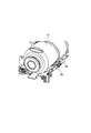
次に、本実施例における現像剤補給容器と現像剤供給装置の概要について説明する。図2は、本実施例における現像剤供給装置(ホッパー)A及び現像剤補給容器(トナーカートリッジ)14の一部の断面図である。
2. 2. Outline of the developer replenishment container and the developer supply device Next, the outline of the developer replenishment container and the developer supply device in this embodiment will be described. FIG. 2 is a cross-sectional view of a part of the developer supply device (hopper) A and the developer supply container (toner cartridge) 14 in this embodiment.
なお、画像形成装置100及びその要素に関し、図1の紙面手前側を正面(前)側、紙面奥側を背面(後)側とする。また、画像形成装置100及びその要素に関し、左右方向は上記正面側から見た場合の左右方向を言うものとする。また、画像形成装置100及びその要素に関して上下方向は、通常の使用状態での重力方向(鉛直方向)の上下方向を言うが、直上、直下のみを意味するものではなく、対象とする位置又は要素を通る水平面に対し上側、下側も含むものである。図2は、右側から見た断面図である。
Regarding the
ホッパーAは、装置本体115の背面側の現像装置104の上部に取り付けられている。また、トナーカートリッジ14は、ホッパーAに対し着脱可能に係合(セット)される。ホッパーAは、現像装置104へのトナーの供給と、トナーカートリッジ14からホッパーA自身へのトナーの補給と、を行う。トナーカートリッジ14は、その長手方向(回転軸線方向)の端部に設けられた供給部30がホッパーAの供給口10を通してホッパーAの内部に挿入されて、ホッパーAに係合される。ホッパーAは、トナーカートリッジ14から補給されたトナーを貯留部18に貯留(一時貯蔵)し、そのトナーを搬送部材としての攪拌スクリュー11、第1のスクリュー12及び第2のスクリュー13によって現像装置104へと搬送して供給する。
The hopper A is attached to the upper part of the developing device 104 on the back side of the device
ホッパーAは、トナーカートリッジ30の供給部30の先端に形成された開口部である補給口(排出口)31を開閉すると共に、トナーカートリッジ30を回転させてトナーカートリッジ14からホッパーAにトナーを補給させる開閉回転機構Bを有する。トナーカートリッジ14が装置本体115に装着されると、開閉回転機構Bのキャップ結合部材16が、トナーカートリッジ14の排出口31を封止しているキャップ15と係合する。これによって、排出口31が開放されると共に、トナーカートリッジ14が回転可能となる。そして、開閉回転機構Bのキャップ結合部材16が回転することでトナーカートリッジ14が回転させられ、トナーカートリッジ14からホッパーAにトナーが補給される。なお、本実施例では、装置本体115に設けられた制御部120(図1)が、ホッパーAを含む画像形成装置100の動作を統括的に制御する。
The hopper A opens and closes a supply port (discharge port) 31 which is an opening formed at the tip of a
3.トナーカートリッジの着脱及びホッパーへのトナー補給
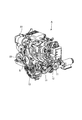
次に、トナーカートリッジ14のホッパーAに対する着脱及びトナーカートリッジ14からホッパーAへのトナー補給について説明する。図3はトナーカートリッジ14を正面側から見た斜視図であり、図4はトナーカートリッジ14の正面側の端部の近傍の斜視図である。また、図5は、トナーカートリッジ14の背面側の端部近傍の斜視図である。
3. 3. Detachment of the toner cartridge and replenishment of toner to the hopper Next, attachment / detachment of the
図3に示すように、トナーカートリッジ14は、ホッパーAに補給するトナーを収容する概略円筒状の収容部14aを有し、収容部14aには螺旋状に内側に突出した搬送部14bが形成されている。トナーカートリッジ14が開閉回転機構Bによって駆動されて回転することで、トナーカートリッジ14の内部に収容されているトナーが正面側から背面側へと搬送される。トナーカートリッジ14の背面側の端部には、収容部14aに収容されたトナーを排出するための排出口31(図8)が先端に形成された、概略円筒状の供給部30が、トナーカートリッジ14の回転軸線方向(長手方向)に突出して設けられている。トナーカートリッジ14の内部のトナーは、供給部30の補給口31まで搬送され、この補給口31からホッパーAの内部に排出される。これにより、ホッパーAの貯留部18(図2)へとトナーを補給することができる。なお、図3においては、トナーカートリッジ14の供給部30はカバー14cで覆われて示されているが、トナーカートリッジ14はこのカバー14cが取り外された後に装置本体115に装着される。
As shown in FIG. 3, the
図3、図4に示すように、トナーカートリッジ14は、装置本体115に設けられた、コロ25を備えたカートリッジトレイ26の上に配置される。これにより、トナーカートリッジ14は、スムーズに回転が行われる。トナーカートリッジ14の補給口31は、後述する開閉回転機構Bによる開放動作が行われるまではキャップ15によって閉じられており、ユーザーやサービス担当者などの操作者が容易に開けることができないようになっている。トナーカートリッジ14は、操作者によってカートリッジトレイ26に沿って装置本体115の正面側から奥側に向けてその回転軸線方向に挿入されることで装置本体115に装着される。このとき、図5に示すように、トナーカートリッジ14のキャップ15と、開閉回転機構Bのキャップ結合部材16とは係合していない。その後、装置本体115においてトナーカートリッジ14が装置本体115に確実に装着されたことが検知されると、開閉回転機構Bが駆動されて、キャップ15を開く開放動作が行われる。なお、トナーカートリッジ14が確実に装着されたことは、装置本体115に設けられたセンサ(図示せず)によってトナーカートリッジ14がカートリッジトレイ26上の所定の位置に装着されたことが検出されることで、制御部120によって検知される。
As shown in FIGS. 3 and 4, the
図6は、開閉回転機構Bの駆動構成を示す背面側から見たホッパーAの斜視図である。開閉回転機構Bは、駆動源としての第1駆動モータ21によって駆動される。キャップ15の開閉は、第1駆動モータ21を図6中の矢印R3で示す方向(時計回り)に正回転させることで行われる。第1駆動モータ21が正回転すると、駆動列Cのギアによって駆動力がカムギア19に伝達され、開閉回転機構Bが駆動される。
FIG. 6 is a perspective view of the hopper A as seen from the rear side showing the drive configuration of the opening / closing rotation mechanism B. The opening / closing rotation mechanism B is driven by a
図7は、開閉回転機構Bのカムギア19の近傍を正面側から見た斜視図である。第1駆動モータ21が正回転すると、カムギア19が図7中の矢印R4方向(反時計回り)に回転させられる。カムギア19の内周にはカム溝(図示せず)が形成されており、カムギア19の半径方向中央部にはそのカム溝と係合するカム突起(図示せず)を備えた円筒部材28が配置されている。円筒部材28は、カムギア19の回転運動に伴ってカムギア19の回転軸線方向に前後運動(往復運動)する。カムギア19が図7中の矢印R4方向に回転すると、円筒部材28が前進動作し、それに伴って円筒部材28の半径方向内側に配置されたキャップ結合部材16も前進運動する。そして、キャップ15に設けられた係合突起37(図5)がキャップ結合部材16とスナップフィットにより係合する。その状態からカムギア19が更に図7中の矢印R4方向に回転すると、円筒部材28が後進動作し、それに伴ってキャップ結合部材16も後進運動する。これにより、キャップ15が排出口31から引き抜かれる。
FIG. 7 is a perspective view of the vicinity of the
図8は、キャップ15とキャップ結合部材16とが係合し、キャップ15が排出口31から引き抜かれた状態におけるトナーカートリッジ14の供給部30の近傍の斜視図である。この状態で、キャップ15は、キャップ結合部材16と係合していると共に、トナーカートリッジ14の供給部30とも係合している(図14)。つまり、キャップ15は、トナーカートリッジ14の回転方向には駆動を伝達できる状態で、トナーカートリッジ14の軸線方向にスライド移動できるように供給部30に取り付けられている。
FIG. 8 is a perspective view of the vicinity of the
一方、トナーカートリッジ14の回転は、第1駆動モータ21を図6中の矢印R3で示す方向とは反対に逆回転させることで行われる。第1駆動モータ21が逆回転すると、駆動力がワンウェイギア20によって分岐し、カートリッジ駆動軸27に伝達される。キャップ結合部材16とカートリッジ駆動軸27とは一体に結合されているため、カートリッジ駆動軸27が回転することによって、キャップ結合部材16が回転する。そして、キャップ結合部材16が回転することによって、キャップ結合部材16と係合しているキャップ15が回転し、トナーカートリッジ14が回転する。これによって、トナーがトナーカートリッジ14の排出口31から排出され、ホッパーA内に補給される。
On the other hand, the rotation of the
次に、図9、図10を参照して、キャップ15の開閉動作について更に説明する。図9は、トナーカートリッジ14とホッパーAとの係合部の近傍を上側から見た断面図である。また、図10は、後述するカートリッジ保持機構36の動作をより詳しく示す拡大図である。
Next, the opening / closing operation of the
図9(a)は、トナーカートリッジ14とホッパーAとの係合を開始する状態を示している。図9(a)の位置では、操作者はトナーカートリッジ14の装置本体115に対する着脱を行うことが可能である。ホッパーAには、トナーカートリッジ14とホッパーAとを係合させる際にトナーカートリッジ14を保持するカートリッジ保持機構36が設けられている。カートリッジ保持機構36は、カートリッジ保持部材35と、このカートリッジ保持部材35を動作させるリンク部材36aと、を備えたリンク機構として構成されている。カートリッジ保持機構36は、ホッパーAの内壁に設置されている。図9(a)の状態では、カートリッジ保持部材35はトナーカートリッジ14を保持する保持位置(図9(c)の位置)から退避している(図10(a))。
FIG. 9A shows a state in which the
図9(b)は、キャップ結合部材16がキャップ15の係合突起37と係合するために図9(b)に示す矢印a方向への動作を開始した状態を示している。このとき、キャップ結合部材16と共に、円筒部材28が図9(b)に示す矢印a方向へ移動して、リンク部材36aを押し上げる。そして、リンク部材36aと連動するカートリッジ保持部材35は、リンク部材36aの移動により、図9(b)に示す矢印d方向へ回動し始める(図10(b))。
FIG. 9B shows a state in which the
図9(c)は、キャップ15の係合突起37がキャップ結合部材16と係合する直前の状態を示している。円筒部材28が十分に図9(c)に示す矢印a方向へ移動したことにより、リンク部材36aが所定の位置まで移動し、カートリッジ保持部材35はトナーカートリッジ14を保持する位置へ移動する。本実施例では、カートリッジ保持部材35は、排出口31の周囲から供給部30の半径方向外側に突出するように形成された被保持部30bに当接して、トナーカートリッジ14を保持する。このとき、リンク部材36aは円筒部材28の外周面によって支持されて位置を固定されるため、カートリッジ保持部材35は所定の位置で固定される(図10(c))。これにより、カートリッジ保持部材35はキャップ15の係合突起37とキャップ結合部材16との係合時にトナーカートリッジ14に作用する矢印a方向の力に対し、トナーカートリッジ14を図9(c)の位置にて保持する。この位置関係は、キャップ15の係合突起37とキャップ結合部材16とが係合するまでに成立する。
FIG. 9C shows a state immediately before the engaging
図9(d)は、キャップ15の係合突起37とキャップ結合部材16とが係合した後、キャップ結合部材16が図9(d)に示す矢印b方向に後退した状態を示している。キャップ15がトナーカートリッジ14から引き抜かれることにより、トナーカートリッジ14の排出口31が露出される(図8)。リンク部材36aは、付勢手段としてのバネ(図示せず)により、図9(a)に示す位置に向けて付勢されているため、キャップ結合部材16と共に円筒部材28が後退することでリンク部材36aの支持はなくなり、リンク部材36aは図9(a)の位置へ戻る。これによって、カートリッジ保持部材35は保持位置から退避し、図9(a)の位置へ戻る。図9(d)の状態で、トナーカートリッジ14は周方向に回転し、トナーの供給を開始するが、カートリッジ保持部材35は退避しているため、トナーカートリッジ14とカートリッジ保持部材35との間で摺擦が生じることはない。
FIG. 9D shows a state in which the
なお、キャップ15で排出口31を封止する際には、上述の動作に解除部材(図示せず)の動作が加わるが、各部材の動作は、概略、図9(d)から図9(a)へと上述とは逆の動作となる。キャップ15は、カートリッジ保持部材35が図9(c)に示す保持位置にある状態で排出口31に圧入される。なお、上記解除部材は、キャップ15の係合突起37をキャップ15の半径方向内側に押圧して、キャップ結合部材16との係合を解除するように作用するものである。
When the
本実施例では、キャップ結合部材16の動作から駆動を受けてカートリッジ保持部材35が動作するため、別途カートリッジ保持部材35を動作させる機構を設ける構成よりコストメリットが高い。また、本実施例では、キャップ結合部材16とカートリッジ保持部材35との両方がホッパーAに設けられている。これにより、キャップ15の係合突起37とキャップ結合部材16との係合時にキャップ結合部材16がトナーカートリッジ14に与える力と、カートリッジ保持部材35がトナーカートリッジ14を支持する力とがホッパーA内で打ち消し合う。その結果、画像形成装置100のホッパーA以外の要素に与える負荷が少なくなる。
In this embodiment, since the
4.ホッパーから現像装置へのトナー供給
次に、ホッパーAから現像装置104へのトナー供給について説明する。図11は、ホッパーAの上方から見た断面図であり、図11中の上側が画像形成装置100の左側、図11中の下側が画像形成装置100の右側である。また、図12は、ホッパーAの背面側から見た断面図である。
4. Toner supply from the hopper to the developing device Next, the toner supply from the hopper A to the developing device 104 will be described. FIG. 11 is a cross-sectional view seen from above of the hopper A, in which the upper side in FIG. 11 is the left side of the
制御部120は、現像装置104内に設けられたセンサ(図示せず)の出力から現像装置104内のトナーが不足したことを検知すると、現像装置104へ最適な量のトナーが供給されるようにホッパーAに信号を送る。ホッパーAは、その信号に応じて駆動され、現像装置104にトナーを供給する。
When the
図11に示すように、ホッパーAの貯留部18に貯留されたトナーは、左側及び右側にそれぞれ設けられた攪拌スクリュー11によって、図11中矢印で示すように正面側から背面側に向かう方向に搬送される。その後、そのトナーは、左右方向の略中央に設けられた第1のスクリュー12によって、図11中矢印で示すように背面側から正面側に向かう方向に、ホッパーAの略中央部へと搬送される。このとき、攪拌スクリュー11は、トナーを撹拌しながらトナーが自然に流れるように搬送するために、トナーの詰まりなどを起こさないような形状とされている。ホッパーAの略中央部に搬送されたトナーは、図12に示すように、ホッパーAの略中央部に設けられた開口部である供給穴18hから重力で落下し、第2のスクリュー13へと搬送される。供給穴18hを通して第2のスクリュー13へと搬送されたトナーは、第2のスクリュー13によって最終的に現像装置104へと搬送される。
As shown in FIG. 11, the toner stored in the
図13は、ホッパーAの駆動構成の全体を示す背面側から見た斜視図である。現像装置104へのトナー供給を要求する信号がホッパーAに送られると、駆動源としての第2駆動モータ22が駆動される。第2駆動モータ22の回転駆動力は、駆動列Dのギアによって図中矢印で示すように攪拌スクリュー11、第1のスクリュー12及び第2のスクリュー13に伝達される。これにより、攪拌スクリュー11、第1のスクリュー12及び第2のスクリュー13が回転して、ホッパーAから現像装置104へとトナーが供給される。
FIG. 13 is a perspective view of the entire drive configuration of the hopper A as viewed from the rear side. When a signal requesting toner supply to the developing device 104 is sent to the hopper A, the
5.貯留部
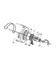
次に、ホッパーAの貯留部18ついて説明する。図14は、貯留部18内がトナーで満たされた状態のホッパーAを右側から見た断面図である。また、図15は、貯留部18内のトナーがある程度消費された状態のホッパーAの右側から見た断面図である。
5. Storage section Next, the
図14に示すように、トナーカートリッジ(トナー容器)14は、その長手方向(回転軸線方向)の端部に設けられた供給部(トナー排出部)30がホッパーAの供給口(開口部)10を通してホッパーAの内部に挿入されてホッパーAに係合される。本実施例では、供給部30は、供給部30の貯留部18への挿入方向に延びた管状形状(円筒形状)を有し、該挿入方向の先端に該挿入方向に開口した排出口31を有する。そして、トナーカートリッジ14からのトナーは、供給部30の先端の排出口31から重力で落下して貯留部18に補給される。
As shown in FIG. 14, in the toner cartridge (toner container) 14, the supply portion (toner discharge portion) 30 provided at the end in the longitudinal direction (rotation axis direction) is the supply port (opening) 10 of the hopper A. It is inserted into the inside of the hopper A through and engaged with the hopper A. In this embodiment, the
貯留部18には、貯留部18内のトナーを検知するための検知部として、貯留部18の内部のトナーの粉面を検知するためのトナーセンサ(トナー検知センサ)17が設けられている。トナーセンサ17は、トナーカートリッジ14から貯留部18にトナーが補給された際にトナーの粉面が接触しながら上昇する貯留部18の壁面18aに設けられている。特に、本実施例では、トナーセンサ17は、正面側の壁面18a1に設けられている。
The
トナーセンサ17は、図14に示すように、その表面にトナーが存在すると、トナーの圧力を感知し、貯留部18内に所定量のトナーが存在する状態であると認識する。一方、ホッパーAから現像装置104にトナーが供給されると、貯留部18内のトナーが消費される。トナーセンサ17は、図15に示すように、その表面にトナーが存在しなくなると、貯留部18内に十分な量のトナーが無い状態であると認識する。すると、ホッパーAは、トナーセンサ17の表面にトナーが存在する状態、すなわち、トナーセンサ17によって貯留部18内のトナーの粉面が検知される状態になるまで、トナーカートリッジ14から貯留部18内にトナーを補給させる。
As shown in FIG. 14, the
なお、ホッパーAにはトナーカートリッジ14との係合部からトナーが外部に飛散することを抑制するためにシーリング用のパッキン33が設けられている。パッキン33は、供給口10の内側に形成された段部10aと、トナーカートリッジ14の供給部30に形成されたフランジ部30aの背面側を向いた面との間に挟まれるように配置されている。
The hopper A is provided with a sealing packing 33 in order to prevent the toner from scattering to the outside from the engaging portion with the
ここで、トナーカートリッジ14から貯留部18内にトナーが補給された際、貯留部18内のトナーは、その粉面が平坦にはならずに、トナーの安息角に基づき略円錐形状になるように蓄積される。ホッパーAの小型化を図りつつ、長時間のコンティニュアスランを実現するためには、貯蔵部18を小型化しつつ、貯留部18内のトナーの充填率を高くすることが望まれる。貯留部18内に貯留するトナーの量をできるだけ多くするためには、図20(b)に示すように貯留部18の壁面18a上にトナーを排出するよりも、図20(a)に示すように貯留部18内の中央付近にトナーを排出することが効果的である。また、本実施例では、トナーの粉面を検知するトナーセンサ17は、貯留部18の壁面18aに設置されている。そのため、貯留部18に蓄積されたトナーは、トナーセンサ17の検知面を通る水平面を底面とした円錐形状に蓄積される。したがって、貯留部18の収容量をなるべく多くするためには、トナーセンサ17を通る水平面で切った断面において貯留部18の略中央にトナーを排出することが望ましい。
Here, when the toner is replenished from the
本実施例では、トナーカートリッジ14は、排出口31が次のような配置となるように、供給部30が重力方向と交差(本実施例では略直交)する方向に貯留部18の内部へと挿入されてホッパーAに係合される。つまり、重力方向に見た場合に、トナーカートリッジ14から貯留部18にトナーが補給された際にトナーの粉面が接触しながら上昇する貯留部18の壁面18aで囲まれた空間内に排出口31が位置するように係合される(図9(d))。特に、本実施例では、排出口31は、トナーセンサ17の検知面を通る水平面で切った断面に対し重力方向に投影した場合に、貯留部18の略中央に位置する。ここで、略中央とは、完全に中央である場合の他、該中央から貯留部18の前後方向、左右方向に、それぞれの方向における貯留部18の幅の20%程度ずれた場合も含む。
In this embodiment, the
更に説明すると、図14に示すように、トナーセンサ17を通る水平面Hで切った断面における、供給口30の貯留部18への挿入方向(装着方向)に沿う貯留部18の幅(内壁間の距離)をL1とする。また、トナーセンサ17を通る水平面Hで切った断面に対し重力方向に投影した場合の、トナーセンサ17が設けられた貯留部18の壁面(側壁)18a(供給部30の挿入方向手前側の壁面18a1)から貯留部18の内側への排出口31の突出量をL2とする。このとき、本実施例では、0.3×L1<L2<0.5×L1を満たすように構成される。また、本実施例では、排出口31は、トナーセンサ17を通る水平面Hで切った断面に対し重力方向に投影した場合に、貯留部18の左右方向の中央に位置する。つまり、開口部31から排出されるトナーは、開口部31から略放物線に沿って貯留部18に排出される。そのため、本実施例では、突出量L2を上記の範囲に設定することで、貯留部18の略中央にトナーが排出されるようにすることができる。
More specifically, as shown in FIG. 14, the width of the storage portion 18 (between the inner walls ) along the insertion direction (mounting direction) of the
しかし、上述のようにトナーカートリッジ14の供給部30を貯留部18の内部に進入させる構成の場合、貯留部18の内部に進入した供給部30がトナーにより汚れることがある。図20(c)に示すように、貯留部18の内部に挿入された供給部30に、トナーカートリッジ14から貯留部18へのトナー補給に伴って貯留部18内で飛散するトナーや、貯留部18内に蓄積したトナーなどが付着することがあるためである。
However, in the case of the configuration in which the
そこで、本実施例では、貯留部18には、供給部30の外側の壁面へのトナーの付着を抑制するために、供給部30に対してトナーを遮蔽する遮蔽部(覆い部)32が設けられている。
Therefore, in the present embodiment, the
6.遮蔽部
まず、図19を参照して、貯留部18に設けられる遮蔽部32の概略構成について説明する。図19(a)は、遮蔽部32が設けられた貯留部18及びトナーカートリッジ14の左側から見た模式的な断面図(右図)、並びに供給部30の貯留部18への挿入方向に沿って背面側から見た供給部30の近傍の側面図(左図)である。なお、図19(b)、(c)は、後述する遮蔽部32の他の例を示す図19(a)と同様の図である。
6. Shielding unit First, the schematic configuration of the shielding
図19(a)に示すように、貯留部18は、貯留部18の内部に挿入された供給部30の重力方向下側の面の少なくとも一部を覆う遮蔽部(突出壁)32を有する構成とする。これにより、貯留部18内で飛散するトナーなどが供給部30に付着することを抑制することができる。
As shown in FIG. 19A, the
ここで、供給部30の貯留部18への挿入方向に見た場合に、遮蔽部32の水平方向の幅は、供給部30の水平方向の幅より大きいことが好ましい。つまり、供給部30の貯留部18への挿入方向に見た場合における、供給部30の水平方向の幅(排出口31の外径)をD1、遮蔽部32の水平方向の幅をD2としたとき、D1<D2を満たすことが好ましい。なお、遮蔽部32は、水平方向において供給部30が内側に収まるように配置される。これにより、貯留部18内で飛散するトナーなどが供給部30に付着することをより効果的に抑制することができる。
Here, when viewed in the direction of insertion of the
また、遮蔽部32は、供給部30の貯留部18への挿入方向(装着方向)において排出口31よりも貯留部18の内側に突出しないようにする。つまり、上述した壁面18aからの排出口31の突出量L2と同方向における、壁面(側壁)18aからの遮蔽部32の突出量をL3としたとき、L2>L3を満たすように構成する。これにより、排出口31から排出されたトナーが遮蔽部32上に積もることを抑制することができる。ただし、L2×0.8<L3を満たすことが好ましい。これにより、遮蔽部32上にトナーが積もることを抑制しつつ、遮蔽部32により供給部30にトナーが付着することを抑制する効果を高めることができる。
Further, the shielding
なお、遮蔽部32は、供給部30の貯留部18への挿入方向において貯留部18の壁面18aから排出口31側の端部まで連続していることが好ましい。これにより、供給部30の壁面側の基部から排出口側の先端近傍までの略全域に、貯留部18内で飛散するトナーなどが付着することを抑制することができる。
The shielding
上述のように、遮蔽部32は、供給部30の重力方向下側の面の少なくとも一部を覆うように設けることで相応の効果が得られる。しかし、図19(b)に示すように、遮蔽部32は、供給部30の貯留部18への挿入方向に見た場合に、供給部30の全周を覆うように設けられていることがより好ましい。これにより、貯留部18内で飛散するトナーなどが供給部30の全周に付着することを抑制することができる。
As described above, the shielding
次に、図14〜図17を参照して、本実施例における遮蔽部32のより具体的な構成について説明する。図16は、背面側から見たホッパーAの断面図である。また、図17は、上方から見たホッパーAの断面図である。
Next, a more specific configuration of the shielding
図14、図15に示すように、本実施例では、貯留部18には、貯留部18の内部に挿入されたトナーカートリッジ14の供給部30の外周を覆うように遮蔽部(突出壁)32が設けられている。この遮蔽部32は、上述したD1<D2、及び、L2×0.8<L3<L2を満たすように構成されており、また供給部30の略全周を覆うように設けられている。
As shown in FIGS. 14 and 15, in the present embodiment, the
図16、図17に示すように、本実施例では、トナーカートリッジ14の開口部31の開閉及びその際のトナーカートリッジ14の保持は、ホッパーAに設けられた開閉回転機構Bによって行われる。前述のように、キャップ15を開閉する際には、カートリッジ保持部材35が供給部30を保持する。本実施例では、カートリッジ保持部材35は、供給部30の左右側部に対向して配置されている。そのため、本実施例では、供給部30を覆う遮蔽部32は、カートリッジ保持部材35と干渉しないように、左右側部に切り込みが入っている。換言すれば、本実施例では、遮蔽部32は、供給部30の重力方向下側の面を覆う第1部分32aと、供給部30の重力方向上側の面を覆う第2部分32bと、を有する。なお、本実施例では、遮蔽部32は、第1部分32a及び第2部分32bによって供給部30の略全周を覆うように設けられているが、前述のように遮蔽部32が重力方向の略下側半周のみを覆う(つまり、第1部分32aのみを有する)構成であってもよい。
As shown in FIGS. 16 and 17, in this embodiment, the opening / closing of the
以上のように、本実施例では、小型化された貯留部18になるべく多くのトナーを収容するために、トナーカートリッジ14の供給部30は貯留部18の内部に挿入され、排出口31が貯留部18の略中央に配置される。本実施例では、このような構成において、貯留部18に供給部30を覆う遮蔽部32を設けることで、比較的簡易で安価な構成で、貯留部18内で飛散するトナーなどが供給部30に付着することを抑制することが可能となる。また、これにより、装置本体115のカートリッジトレイ26がトナーで汚れることや、トナーカートリッジ14の挿抜を繰り返すことでカートリッジトレイ26やトナーカートリッジ14のトナーによる汚れが助長されることを抑制することができる。
As described above, in this embodiment, in order to accommodate as much toner as possible in the
[実施例2]
次に、本発明の他の実施例について説明する。本実施例の画像形成装置の基本的な構成及び動作は、実施例1のものと同じである。したがって、本実施例において実施例1のものと同一又は対応する機能あるいは構成を有する要素については、実施例1と同一の符号を付して詳しい説明は省略する。
[Example 2]
Next, other examples of the present invention will be described. The basic configuration and operation of the image forming apparatus of this embodiment are the same as those of the first embodiment. Therefore, in this embodiment, elements having the same or corresponding functions or configurations as those in the first embodiment are designated by the same reference numerals as those in the first embodiment, and detailed description thereof will be omitted.
本実施例では、実施例1と同様に、貯留部18には、貯留部18の内部に挿入されたトナーカートリッジ14の供給部30の外周を覆うように遮蔽部(突出壁)32が設けられている。そして、本実施例では、概略、図19(c)に示すように、遮蔽部32と供給部30との間に封止部材34が設けられることが実施例1とは異なる。
In this embodiment, similarly to the first embodiment, the
図18を参照して、本実施例における封止部材34のより具体的な構成について説明する。図18は、本実施例におけるホッパーAの封止部材34の近傍を右側から見た断面図である。本実施例では、排出口31に隣接する遮蔽部32の内周面の略全周(図16の第1部分32a、第2部分32bのそれぞれの内周面)に、封止部材34が設けられている。本実施例では、封止部材34は、弾性を有する発泡部材で形成されている。この封止部材34は、供給部30の端部に形成された被保持部30bの正面側を向いた面と当接して、遮蔽部32と供給部30との間を封止する。なお、トナーカートリッジ14をホッパーAに対し挿抜する際には、トナーカートリッジ14の上記被保持部30bは封止部材34を変形させてこれを通過するようになっている。
A more specific configuration of the sealing
なお、図19(c)に示すように遮蔽部32が供給部30の全周を覆うように連続して設けられている場合、封止部材34は遮蔽部32と供給部30との間に配置された連続したリング状の部材とすることができる。
When the shielding
このように、封止部材34を設けることで、貯留部18内で飛散するトナーなどが供給部30と遮蔽部32との間に進入することを抑制することができる。これにより、貯留部18内で飛散するトナーなどが供給部30の外周面や遮蔽部32の内周面に付着することを抑制することが可能となる。また、封止部材34を設けることで、封止部材34よりも貯留部18の内側に位置する供給部30に付着したトナーを、トナーカートリッジ14のホッパーAに対する挿抜時に掻き落とす効果も得られる。
By providing the sealing
[その他]
以上、本発明を具体的な実施例に即して説明したが、本発明は上述の実施例に限定されるものではない。
[Other]
Although the present invention has been described above with reference to specific examples, the present invention is not limited to the above-mentioned examples.
上述の実施例では、現像剤補給容器から現像剤供給装置に補給する現像剤はトナーであったが、現像剤補給容器から現像剤供給装置に補給する現像剤はトナーとキャリアとを含む二成分現像剤であってもよい。また、トナーとキャリアとを別個に補給する構成にあっては、現像剤補給容器から現像剤供給装置に補給する現像剤はキャリアのみであってもよい。 In the above embodiment, the developer supplied from the developer supply container to the developer supply device is toner, but the developer supplied from the developer supply container to the developer supply device has two components including toner and a carrier. It may be a developer. Further, in the configuration in which the toner and the carrier are replenished separately, only the carrier may be replenished from the developer replenishment container to the developer supply device.
14 現像剤補給容器(トナーカートリッジ)
15 キャップ
17 トナーセンサ
18 貯留部
26 カートリッジトレイ
30 供給部
31 排出口
32 遮蔽部
34 封止部材
35 カートリッジ保持部材
A 現像剤供給装置(ホッパー)
B 開閉回転機構
100 画像形成装置
14 Developer supply container (toner cartridge)
15
B Open /
Claims (8)
像担持体に形成された静電像をトナーを用いて現像する現像装置と、
前記画像形成装置に装着可能であり、トナーを収容し、収容されたトナーを排出する排出口を含むトナー排出部を有するトナー容器と、
前記排出口から排出されたトナーを貯留する貯留部を有し、前記貯留部に貯留されたトナーを前記現像装置に供給する供給装置と、
を備え、
前記画像形成装置に前記トナー容器が装着された状態において、
前記トナー排出部は、前記貯留部の開口部を介して前記貯留部の内部に侵入しており、
前記トナー容器が前記画像形成装置に装着される装着方向に関して、前記貯留部の内部の前記開口部が設けられている側の第一側壁から前記貯留部の内部の前記第一側壁とは反対側の第二側壁までの長さをL1とし、前記トナー排出部が前記貯留部の内部の前記第一側壁から前記貯留部の内部に侵入している長さをL2としたとき、L1×0.3<L2<L1×0.5を満たし、
少なくとも前記トナー排出部よりも鉛直方向下方には、前記貯留部の内部のトナーが付着することが抑制されるよう前記トナー排出部を覆うための覆い部が、前記貯留部の内部の前記第一側壁から前記貯留部の内部に突出して設けられていることを特徴とする画像形成装置。 An image forming apparatus,
A developing device that develops an electrostatic image formed on an image carrier using toner,
A toner container that can be attached to the image forming apparatus and has a toner discharge portion including a discharge port that stores toner and discharges the stored toner.
Have a reservoir for storing the toner discharged from the discharge port, and a supply device for supplying the toner stored in the storage portion to the developing device,
With
In a state where the toner container is attached to the image forming apparatus
The toner discharging portion is penetrated inside of the reservoir through the opening of the reservoir,
Respect mounting direction front Symbol toner container is mounted to the image forming apparatus, contrary to the interior of the first side wall of the interior of the said reservoir from a first side wall on the side where the opening is provided in the reservoir When the length to the second side wall on the side is L1 and the length of the toner discharging portion invading the inside of the storage portion from the first side wall inside the storage portion is L2, L1 × 0 .3 <L2 <L1 × 0.5,
At least below the toner discharging portion in the vertical direction, a covering portion for covering the toner discharging portion is provided inside the storage portion so that the toner inside the storage portion is suppressed from adhering. An image forming apparatus characterized in that it is provided so as to project from a side wall into the inside of the storage portion .
前記覆い部は、円筒形状であり、
前記画像形成装置に前記トナー容器が装着された状態において、前記覆い部は、前記トナー排出部の全周にわたって配置されていることを特徴とする請求項1乃至3のいずれか1項に記載の画像形成装置。 The toner discharging portion has a cylindrical shape and has a cylindrical shape.
The covering portion has a cylindrical shape and has a cylindrical shape.
The method according to any one of claims 1 to 3 , wherein the covering portion is arranged over the entire circumference of the toner discharging portion in a state where the toner container is attached to the image forming apparatus . Image forming device.
前記覆い部は、円筒形状であり、
前記トナー排出部の外径をD1とし、前記覆い部の外径をD2としたとき、D1<D2を満たすことを特徴とする請求項1乃至3のいずれか1項に記載の画像形成装置。 The toner discharging portion has a cylindrical shape and has a cylindrical shape.
The covering portion has a cylindrical shape and has a cylindrical shape.
The image forming apparatus according to any one of claims 1 to 3 , wherein when the outer diameter of the toner discharging portion is D1 and the outer diameter of the covering portion is D2, D1 <D2 is satisfied.
Priority Applications (2)
| Application Number | Priority Date | Filing Date | Title |
|---|---|---|---|
| JP2016091307A JP6800605B2 (en) | 2016-04-28 | 2016-04-28 | Image forming device |
| US15/498,579 US10088778B2 (en) | 2016-04-28 | 2017-04-27 | Image forming apparatus having a toner discharging portion and a cover |
Applications Claiming Priority (1)
| Application Number | Priority Date | Filing Date | Title |
|---|---|---|---|
| JP2016091307A JP6800605B2 (en) | 2016-04-28 | 2016-04-28 | Image forming device |
Publications (3)
| Publication Number | Publication Date |
|---|---|
| JP2017198921A JP2017198921A (en) | 2017-11-02 |
| JP2017198921A5 JP2017198921A5 (en) | 2019-05-30 |
| JP6800605B2 true JP6800605B2 (en) | 2020-12-16 |
Family
ID=60157068
Family Applications (1)
| Application Number | Title | Priority Date | Filing Date |
|---|---|---|---|
| JP2016091307A Active JP6800605B2 (en) | 2016-04-28 | 2016-04-28 | Image forming device |
Country Status (2)
| Country | Link |
|---|---|
| US (1) | US10088778B2 (en) |
| JP (1) | JP6800605B2 (en) |
Family Cites Families (6)
| Publication number | Priority date | Publication date | Assignee | Title |
|---|---|---|---|---|
| JP3364632B2 (en) * | 1994-11-08 | 2003-01-08 | 株式会社リコー | Toner supply device |
| US6091912A (en) * | 1998-01-26 | 2000-07-18 | Ricoh Company, Ltd. | Tower supplying device and image forming apparatus using same toner supplying device |
| JP3562959B2 (en) | 1998-05-13 | 2004-09-08 | 株式会社リコー | Toner supply device and toner container used therein |
| JP3691489B2 (en) | 2003-02-03 | 2005-09-07 | 株式会社リコー | Toner bottle |
| JP3991017B2 (en) | 2003-08-29 | 2007-10-17 | キヤノン株式会社 | Toner supply device |
| JP5866223B2 (en) | 2012-02-17 | 2016-02-17 | シャープ株式会社 | Intermediate hopper and image forming apparatus having the same |
-
2016
- 2016-04-28 JP JP2016091307A patent/JP6800605B2/en active Active
-
2017
- 2017-04-27 US US15/498,579 patent/US10088778B2/en active Active
Also Published As
| Publication number | Publication date |
|---|---|
| JP2017198921A (en) | 2017-11-02 |
| US20170315476A1 (en) | 2017-11-02 |
| US10088778B2 (en) | 2018-10-02 |
Similar Documents
| Publication | Publication Date | Title |
|---|---|---|
| US7738817B2 (en) | Developer supply container and image forming apparatus | |
| JP6213706B2 (en) | Developer container and image forming apparatus | |
| EP1220052A2 (en) | Developer container and image forming apparatus | |
| US20090232548A1 (en) | Waste toner recovery system and method | |
| US8594539B2 (en) | Outlet recess for a powder container for an image forming apparatus | |
| US20120099887A1 (en) | Image forming apparatus | |
| JP4459025B2 (en) | Developer supply container | |
| JP2007093697A (en) | Developer supply container | |
| EP2610685B1 (en) | Developer storage container, image forming unit and image forming apparatus | |
| JP5488743B2 (en) | Powder container and image forming apparatus | |
| US20120099892A1 (en) | Attaching and detaching body and image forming apparatus | |
| US9042774B2 (en) | Cartridge and image forming apparatus | |
| JP4591474B2 (en) | Method for regenerating developer container | |
| JP4729317B2 (en) | Packaging material and toner container for replacement toner container to be attached to and detached from the image forming apparatus | |
| JP6800605B2 (en) | Image forming device | |
| JP6380646B2 (en) | Developer container and image forming apparatus including the same | |
| JP3774582B2 (en) | Image forming apparatus | |
| JP7249511B2 (en) | image forming device | |
| JP4260204B2 (en) | Print process cartridge and image forming apparatus | |
| JP2011158509A (en) | Toner replenishing device | |
| CN110320768B (en) | Toner container and image forming apparatus | |
| JP4477087B2 (en) | Developer storage container and image forming apparatus | |
| JP4308631B2 (en) | Development device | |
| CN112596358B (en) | Toner container and image forming apparatus | |
| JP2003223045A (en) | Developing device and image forming apparatus |
Legal Events
| Date | Code | Title | Description |
|---|---|---|---|
| A521 | Request for written amendment filed |
Free format text: JAPANESE INTERMEDIATE CODE: A523 Effective date: 20190419 |
|
| A621 | Written request for application examination |
Free format text: JAPANESE INTERMEDIATE CODE: A621 Effective date: 20190419 |
|
| A131 | Notification of reasons for refusal |
Free format text: JAPANESE INTERMEDIATE CODE: A131 Effective date: 20200212 |
|
| A977 | Report on retrieval |
Free format text: JAPANESE INTERMEDIATE CODE: A971007 Effective date: 20200212 |
|
| A601 | Written request for extension of time |
Free format text: JAPANESE INTERMEDIATE CODE: A601 Effective date: 20200406 |
|
| A521 | Request for written amendment filed |
Free format text: JAPANESE INTERMEDIATE CODE: A523 Effective date: 20200518 |
|
| TRDD | Decision of grant or rejection written | ||
| A01 | Written decision to grant a patent or to grant a registration (utility model) |
Free format text: JAPANESE INTERMEDIATE CODE: A01 Effective date: 20201027 |
|
| A61 | First payment of annual fees (during grant procedure) |
Free format text: JAPANESE INTERMEDIATE CODE: A61 Effective date: 20201125 |
|
| R151 | Written notification of patent or utility model registration |
Ref document number: 6800605 Country of ref document: JP Free format text: JAPANESE INTERMEDIATE CODE: R151 |