JP6799463B2 - Optical interrogation system - Google Patents
Optical interrogation system Download PDFInfo
- Publication number
- JP6799463B2 JP6799463B2 JP2016540345A JP2016540345A JP6799463B2 JP 6799463 B2 JP6799463 B2 JP 6799463B2 JP 2016540345 A JP2016540345 A JP 2016540345A JP 2016540345 A JP2016540345 A JP 2016540345A JP 6799463 B2 JP6799463 B2 JP 6799463B2
- Authority
- JP
- Japan
- Prior art keywords
- target
- model
- sensor
- light
- ewc
- Prior art date
- Legal status (The legal status is an assumption and is not a legal conclusion. Google has not performed a legal analysis and makes no representation as to the accuracy of the status listed.)
- Active
Links
- 230000003287 optical effect Effects 0.000 title claims description 60
- 238000011282 treatment Methods 0.000 claims description 59
- 210000004072 lung Anatomy 0.000 claims description 54
- 238000000034 method Methods 0.000 claims description 47
- 238000002059 diagnostic imaging Methods 0.000 claims description 20
- 230000001225 therapeutic effect Effects 0.000 claims description 10
- 238000004611 spectroscopical analysis Methods 0.000 claims description 9
- 239000007850 fluorescent dye Substances 0.000 claims description 7
- 230000029058 respiratory gaseous exchange Effects 0.000 claims description 6
- 230000008569 process Effects 0.000 claims description 5
- 230000005540 biological transmission Effects 0.000 claims description 3
- 239000002131 composite material Substances 0.000 claims description 3
- 230000037361 pathway Effects 0.000 claims description 3
- 230000000241 respiratory effect Effects 0.000 claims description 3
- 238000004364 calculation method Methods 0.000 claims description 2
- 230000010354 integration Effects 0.000 claims description 2
- 238000003325 tomography Methods 0.000 claims description 2
- 210000001519 tissue Anatomy 0.000 description 32
- 238000002591 computed tomography Methods 0.000 description 18
- 210000000621 bronchi Anatomy 0.000 description 15
- 238000013439 planning Methods 0.000 description 14
- 238000012806 monitoring device Methods 0.000 description 12
- 210000003437 trachea Anatomy 0.000 description 11
- 210000003097 mucus Anatomy 0.000 description 9
- 238000001574 biopsy Methods 0.000 description 8
- 210000003123 bronchiole Anatomy 0.000 description 8
- 210000004877 mucosa Anatomy 0.000 description 8
- 230000006870 function Effects 0.000 description 7
- 230000003211 malignant effect Effects 0.000 description 7
- 210000002460 smooth muscle Anatomy 0.000 description 7
- 238000001228 spectrum Methods 0.000 description 7
- 238000002595 magnetic resonance imaging Methods 0.000 description 5
- 230000001360 synchronised effect Effects 0.000 description 5
- 238000012790 confirmation Methods 0.000 description 4
- 208000037265 diseases, disorders, signs and symptoms Diseases 0.000 description 4
- 238000005516 engineering process Methods 0.000 description 4
- 239000003550 marker Substances 0.000 description 4
- 210000005036 nerve Anatomy 0.000 description 4
- 210000000056 organ Anatomy 0.000 description 4
- 238000012800 visualization Methods 0.000 description 4
- 208000006545 Chronic Obstructive Pulmonary Disease Diseases 0.000 description 3
- 208000006673 asthma Diseases 0.000 description 3
- 239000008280 blood Substances 0.000 description 3
- 210000004369 blood Anatomy 0.000 description 3
- 230000008859 change Effects 0.000 description 3
- 238000004891 communication Methods 0.000 description 3
- 201000010099 disease Diseases 0.000 description 3
- 230000003902 lesion Effects 0.000 description 3
- 230000007246 mechanism Effects 0.000 description 3
- 239000013307 optical fiber Substances 0.000 description 3
- 238000012634 optical imaging Methods 0.000 description 3
- 238000012545 processing Methods 0.000 description 3
- 230000004044 response Effects 0.000 description 3
- 238000001356 surgical procedure Methods 0.000 description 3
- 102000001554 Hemoglobins Human genes 0.000 description 2
- 108010054147 Hemoglobins Proteins 0.000 description 2
- 208000019693 Lung disease Diseases 0.000 description 2
- 230000002159 abnormal effect Effects 0.000 description 2
- 238000010521 absorption reaction Methods 0.000 description 2
- 230000000712 assembly Effects 0.000 description 2
- 238000000429 assembly Methods 0.000 description 2
- 210000000845 cartilage Anatomy 0.000 description 2
- 238000013170 computed tomography imaging Methods 0.000 description 2
- 239000003814 drug Substances 0.000 description 2
- 239000000975 dye Substances 0.000 description 2
- 238000003384 imaging method Methods 0.000 description 2
- 238000007726 management method Methods 0.000 description 2
- 238000005259 measurement Methods 0.000 description 2
- 238000012986 modification Methods 0.000 description 2
- 230000004048 modification Effects 0.000 description 2
- 230000011514 reflex Effects 0.000 description 2
- 238000009877 rendering Methods 0.000 description 2
- 238000012552 review Methods 0.000 description 2
- 239000007787 solid Substances 0.000 description 2
- 210000003462 vein Anatomy 0.000 description 2
- 208000000059 Dyspnea Diseases 0.000 description 1
- 206010013975 Dyspnoeas Diseases 0.000 description 1
- 206010014561 Emphysema Diseases 0.000 description 1
- 230000009471 action Effects 0.000 description 1
- 230000002411 adverse Effects 0.000 description 1
- 238000004458 analytical method Methods 0.000 description 1
- 238000013459 approach Methods 0.000 description 1
- 210000004204 blood vessel Anatomy 0.000 description 1
- 230000002638 denervation Effects 0.000 description 1
- 238000001514 detection method Methods 0.000 description 1
- 229940079593 drug Drugs 0.000 description 1
- 230000000694 effects Effects 0.000 description 1
- 230000005057 finger movement Effects 0.000 description 1
- 238000002594 fluoroscopy Methods 0.000 description 1
- 238000002599 functional magnetic resonance imaging Methods 0.000 description 1
- 230000001771 impaired effect Effects 0.000 description 1
- 238000010348 incorporation Methods 0.000 description 1
- 210000000867 larynx Anatomy 0.000 description 1
- 230000004199 lung function Effects 0.000 description 1
- 238000013507 mapping Methods 0.000 description 1
- 238000012544 monitoring process Methods 0.000 description 1
- 238000012014 optical coherence tomography Methods 0.000 description 1
- 230000007170 pathology Effects 0.000 description 1
- 230000002093 peripheral effect Effects 0.000 description 1
- 210000003800 pharynx Anatomy 0.000 description 1
- 230000002685 pulmonary effect Effects 0.000 description 1
- 238000002601 radiography Methods 0.000 description 1
- 210000002345 respiratory system Anatomy 0.000 description 1
- 230000011218 segmentation Effects 0.000 description 1
- 230000007480 spreading Effects 0.000 description 1
- 238000011272 standard treatment Methods 0.000 description 1
- 239000000126 substance Substances 0.000 description 1
- 239000013589 supplement Substances 0.000 description 1
- 230000008685 targeting Effects 0.000 description 1
- 230000001131 transforming effect Effects 0.000 description 1
- 238000011179 visual inspection Methods 0.000 description 1
- 238000007794 visualization technique Methods 0.000 description 1
- XLYOFNOQVPJJNP-UHFFFAOYSA-N water Substances O XLYOFNOQVPJJNP-UHFFFAOYSA-N 0.000 description 1
Images


Classifications
-
- A—HUMAN NECESSITIES
- A61—MEDICAL OR VETERINARY SCIENCE; HYGIENE
- A61B—DIAGNOSIS; SURGERY; IDENTIFICATION
- A61B5/00—Measuring for diagnostic purposes; Identification of persons
- A61B5/08—Detecting, measuring or recording devices for evaluating the respiratory organs
-
- A—HUMAN NECESSITIES
- A61—MEDICAL OR VETERINARY SCIENCE; HYGIENE
- A61B—DIAGNOSIS; SURGERY; IDENTIFICATION
- A61B1/00—Instruments for performing medical examinations of the interior of cavities or tubes of the body by visual or photographical inspection, e.g. endoscopes; Illuminating arrangements therefor
- A61B1/267—Instruments for performing medical examinations of the interior of cavities or tubes of the body by visual or photographical inspection, e.g. endoscopes; Illuminating arrangements therefor for the respiratory tract, e.g. laryngoscopes, bronchoscopes
- A61B1/2676—Bronchoscopes
-
- A—HUMAN NECESSITIES
- A61—MEDICAL OR VETERINARY SCIENCE; HYGIENE
- A61B—DIAGNOSIS; SURGERY; IDENTIFICATION
- A61B34/00—Computer-aided surgery; Manipulators or robots specially adapted for use in surgery
- A61B34/20—Surgical navigation systems; Devices for tracking or guiding surgical instruments, e.g. for frameless stereotaxis
-
- A—HUMAN NECESSITIES
- A61—MEDICAL OR VETERINARY SCIENCE; HYGIENE
- A61B—DIAGNOSIS; SURGERY; IDENTIFICATION
- A61B5/00—Measuring for diagnostic purposes; Identification of persons
- A61B5/0059—Measuring for diagnostic purposes; Identification of persons using light, e.g. diagnosis by transillumination, diascopy, fluorescence
- A61B5/0082—Measuring for diagnostic purposes; Identification of persons using light, e.g. diagnosis by transillumination, diascopy, fluorescence adapted for particular medical purposes
- A61B5/0084—Measuring for diagnostic purposes; Identification of persons using light, e.g. diagnosis by transillumination, diascopy, fluorescence adapted for particular medical purposes for introduction into the body, e.g. by catheters
-
- A—HUMAN NECESSITIES
- A61—MEDICAL OR VETERINARY SCIENCE; HYGIENE
- A61B—DIAGNOSIS; SURGERY; IDENTIFICATION
- A61B5/00—Measuring for diagnostic purposes; Identification of persons
- A61B5/06—Devices, other than using radiation, for detecting or locating foreign bodies ; determining position of probes within or on the body of the patient
- A61B5/061—Determining position of a probe within the body employing means separate from the probe, e.g. sensing internal probe position employing impedance electrodes on the surface of the body
-
- A—HUMAN NECESSITIES
- A61—MEDICAL OR VETERINARY SCIENCE; HYGIENE
- A61B—DIAGNOSIS; SURGERY; IDENTIFICATION
- A61B5/00—Measuring for diagnostic purposes; Identification of persons
- A61B5/06—Devices, other than using radiation, for detecting or locating foreign bodies ; determining position of probes within or on the body of the patient
- A61B5/065—Determining position of the probe employing exclusively positioning means located on or in the probe, e.g. using position sensors arranged on the probe
- A61B5/066—Superposing sensor position on an image of the patient, e.g. obtained by ultrasound or x-ray imaging
-
- A—HUMAN NECESSITIES
- A61—MEDICAL OR VETERINARY SCIENCE; HYGIENE
- A61B—DIAGNOSIS; SURGERY; IDENTIFICATION
- A61B5/00—Measuring for diagnostic purposes; Identification of persons
- A61B5/103—Detecting, measuring or recording devices for testing the shape, pattern, colour, size or movement of the body or parts thereof, for diagnostic purposes
- A61B5/11—Measuring movement of the entire body or parts thereof, e.g. head or hand tremor, mobility of a limb
- A61B5/113—Measuring movement of the entire body or parts thereof, e.g. head or hand tremor, mobility of a limb occurring during breathing
-
- A—HUMAN NECESSITIES
- A61—MEDICAL OR VETERINARY SCIENCE; HYGIENE
- A61B—DIAGNOSIS; SURGERY; IDENTIFICATION
- A61B5/00—Measuring for diagnostic purposes; Identification of persons
- A61B5/72—Signal processing specially adapted for physiological signals or for diagnostic purposes
- A61B5/7203—Signal processing specially adapted for physiological signals or for diagnostic purposes for noise prevention, reduction or removal
- A61B5/7207—Signal processing specially adapted for physiological signals or for diagnostic purposes for noise prevention, reduction or removal of noise induced by motion artifacts
-
- A—HUMAN NECESSITIES
- A61—MEDICAL OR VETERINARY SCIENCE; HYGIENE
- A61B—DIAGNOSIS; SURGERY; IDENTIFICATION
- A61B5/00—Measuring for diagnostic purposes; Identification of persons
- A61B5/74—Details of notification to user or communication with user or patient ; user input means
- A61B5/742—Details of notification to user or communication with user or patient ; user input means using visual displays
- A61B5/7425—Displaying combinations of multiple images regardless of image source, e.g. displaying a reference anatomical image with a live image
-
- A—HUMAN NECESSITIES
- A61—MEDICAL OR VETERINARY SCIENCE; HYGIENE
- A61B—DIAGNOSIS; SURGERY; IDENTIFICATION
- A61B5/00—Measuring for diagnostic purposes; Identification of persons
- A61B5/0059—Measuring for diagnostic purposes; Identification of persons using light, e.g. diagnosis by transillumination, diascopy, fluorescence
- A61B5/0062—Arrangements for scanning
- A61B5/0066—Optical coherence imaging
-
- A—HUMAN NECESSITIES
- A61—MEDICAL OR VETERINARY SCIENCE; HYGIENE
- A61B—DIAGNOSIS; SURGERY; IDENTIFICATION
- A61B5/00—Measuring for diagnostic purposes; Identification of persons
- A61B5/0059—Measuring for diagnostic purposes; Identification of persons using light, e.g. diagnosis by transillumination, diascopy, fluorescence
- A61B5/0075—Measuring for diagnostic purposes; Identification of persons using light, e.g. diagnosis by transillumination, diascopy, fluorescence by spectroscopy, i.e. measuring spectra, e.g. Raman spectroscopy, infrared absorption spectroscopy
-
- A—HUMAN NECESSITIES
- A61—MEDICAL OR VETERINARY SCIENCE; HYGIENE
- A61B—DIAGNOSIS; SURGERY; IDENTIFICATION
- A61B5/00—Measuring for diagnostic purposes; Identification of persons
- A61B5/06—Devices, other than using radiation, for detecting or locating foreign bodies ; determining position of probes within or on the body of the patient
- A61B5/061—Determining position of a probe within the body employing means separate from the probe, e.g. sensing internal probe position employing impedance electrodes on the surface of the body
- A61B5/062—Determining position of a probe within the body employing means separate from the probe, e.g. sensing internal probe position employing impedance electrodes on the surface of the body using magnetic field
Description
本開示は、光を用いて肺を可視化するためのシステムおよび方法に関する。より詳細には、本開示は、他の画像診断法によって得られた画像を肺の気道の光可視画像で増補し、かつ肺組織の種類を特定するシステムおよび方法に関する。 The present disclosure relates to systems and methods for visualizing the lungs with light. More specifically, the present disclosure relates to systems and methods that augment images obtained by other diagnostic imaging methods with photovisual images of the airways of the lung and identify the type of lung tissue.
喘息、慢性閉塞性肺疾患(COPD)および慢性閉塞性肺疾患(COLD)などの肺疾患または肺関連疾患のための標準治療は一般に、主として患者に非常に侵襲的な医学的管理および/または医薬品管理に焦点を当てている。例えば、局所的かつ侵襲的手段(例えば外科手術)による肺除神経は喘息または気腫に治療効果を与えることができるということが何十年にもわたって報告されている。 Standard treatments for lung or lung-related disorders such as asthma, chronic obstructive pulmonary disease (COPD) and chronic obstructive pulmonary disease (COLD) are generally highly invasive medical management and / or pharmaceuticals primarily to patients. Focus on management. For example, it has been reported for decades that pulmonary denervation by local and invasive means (eg surgery) can have a therapeutic effect on asthma or emphysema.
電磁ナビゲーション(EMN)は、肺などの管腔網の治療の可能性の拡大に寄与している。EMNは、コンピュータ断層撮影(CT)スキャン、磁気共鳴画像(MRI)法または蛍光透視法などの非侵襲的画像診断法に依存している。これらの非侵襲的画像診断法と組み合わせたEMNは、標的の位置を特定し、かつ臨床医が肺の管腔網を標的までナビゲートするのを支援するためにも使用されている。しかし、これらの非侵襲的画像診断法によって生成される画像は、管腔網に平行に走る神経の位置のような特徴を特定するのに十分な解像度を提供できていない。さらに、治療を行う際にこれらの非侵襲的画像診断法を用いてさらなる画像診断を行い、治療が完了したか否かを判定しなければならない。それにより有害なX線や物質の患者への曝露数や治療コストが上昇してしまう。なおさらに、治療されている領域のより高い解像度が常に望まれている。従って、より高い解像度が得られ、かつ手術において臨床的に効率的な画像診断法が現在も必要とされている。 Electromagnetic navigation (EMN) contributes to expanding the therapeutic potential of luminal networks such as the lungs. EMN relies on non-invasive diagnostic imaging techniques such as computed tomography (CT) scans, magnetic resonance imaging (MRI) or fluoroscopy. EMNs combined with these non-invasive diagnostic imaging methods have also been used to locate targets and assist clinicians in navigating the luminal network of the lungs to targets. However, the images produced by these non-invasive diagnostic imaging methods have not provided sufficient resolution to identify features such as the location of nerves running parallel to the luminal network. In addition, these non-invasive diagnostic imaging methods must be used to perform further diagnostic imaging during treatment to determine if treatment is complete. As a result, the number of exposures of harmful X-rays and substances to patients and the cost of treatment increase. Furthermore, higher resolution of the area being treated is always desired. Therefore, there is still a need for diagnostic imaging methods that provide higher resolution and are clinically efficient in surgery.
一態様では、本開示は、肺の光インタロゲーションシステムを特徴とする。本システムは、メモリ、電磁(EM)ボード、伸長式作業チャネル(EWC)、EMセンサ、光源、光受信機およびプロセッサを備える。メモリは管腔網の3Dモデルおよび管腔網の経路計画を格納し、EMボードはEM場を発生するように構成されている。EWCは、経路計画に従い標的に向かって患者の管腔網をナビゲートし、EMセンサはEWCの遠位端から遠位に延在し、かつEM場を感知するように構成されている。光源はEWCまたはその周囲に位置し、かつ発光するように構成されており、光受信機はEWCまたはその周囲に位置し、かつ管腔網の気道から反射された光を感知するように構成されている。プロセッサは、反射光を光データに変換するように構成され、かつ、組織の種類もしくは密度を特定するか、1つ以上の血管の存在を特定するか、可視画像を生成するか、あるいは光データを3Dモデルと統合するように構成されている。 In one aspect, the present disclosure features a lung optical interrogation system. The system includes memory, an electromagnetic (EM) board, an extendable work channel (EWC), an EM sensor, a light source, an optical receiver and a processor. The memory stores a 3D model of the lumen network and the routing plan of the lumen network, and the EM board is configured to generate an EM field. The EWC navigates the patient's luminal network towards the target according to a route plan, and the EM sensor extends distally from the distal end of the EWC and is configured to sense the EM field. The light source is located at or around the EWC and is configured to emit light, and the light receiver is located at or around the EWC and is configured to sense the light reflected from the airways of the luminal network. ing. The processor is configured to convert reflected light into optical data and identifies the type or density of tissue, the presence of one or more blood vessels, produces a visible image, or optical data. Is configured to integrate with the 3D model.
一態様では、本システムは、3Dモデルと統合された光データを表示するように構成された表示装置をさらに備える。表示装置はEMセンサの位置に基づき状況を表示するようにさらに構成されている。その状況は、EMセンサが標的内でない位置、標的の位置、または健康な組織に隣接する位置にあるか否か、および標的の治療が完了したか否かを示してもよい。生成された画像は管腔網の内部を示す。 In one aspect, the system further comprises a display device configured to display optical data integrated with a 3D model. The display device is further configured to display the status based on the position of the EM sensor. The situation may indicate whether the EM sensor is not within the target, at the target, or adjacent to healthy tissue, and whether the treatment of the target is complete. The generated image shows the inside of the lumen network.
一態様では、生成された可視画像の解像度は3Dモデルの解像度よりも高い。 In one aspect, the resolution of the generated visible image is higher than the resolution of the 3D model.
別の態様では、光源および光受信機はEWCの遠位端またはその周囲に位置している。 In another aspect, the light source and light receiver are located at or around the distal end of the EWC.
別の態様では、生成された画像の統合位置は3DモデルにおけるEMセンサの位置に基づいている。 In another aspect, the integrated position of the generated image is based on the position of the EM sensor in the 3D model.
別の態様では、プロセッサは、光データに基づき治療装置が標的の位置にあるか否かを判定するようにさらに構成されている。 In another aspect, the processor is further configured to determine if the treatment device is in a target position based on optical data.
さらに別の態様では、プロセッサは、光データによる標的の密度に基づき治療の十分性を判定するようにさらに構成されている。 In yet another aspect, the processor is further configured to determine the adequacy of treatment based on the density of targets by optical data.
さらに別の態様では、プロセッサは、蛍光染料で染色された標的の蛍光色の変化に基づき治療の十分性を判定するようにさらに構成されている。 In yet another aspect, the processor is further configured to determine the adequacy of treatment based on changes in the fluorescent color of the target stained with the fluorescent dye.
なおさらに別の態様では、プロセッサは、肺組織の反射パターンに基づき予測アルゴリズムを用いて分光分析を行う。 In yet another embodiment, the processor performs spectroscopic analysis using a prediction algorithm based on the reflex pattern of lung tissue.
別の態様では、光源および光受信機は、共焦点画像診断装置または光干渉断層撮影装置に一体化されている。 In another aspect, the light source and optical receiver are integrated into a confocal diagnostic imaging device or an optical coherence tomography device.
別の態様では、プロセッサはEMセンサと光受信機との間の離間距離を測定するようにさらに構成されている。光データの3Dモデルとの統合はその離間距離に基づいている。 In another aspect, the processor is further configured to measure the distance between the EM sensor and the optical receiver. The integration of optical data with a 3D model is based on its distance.
別の態様では、本システムは患者の体表に位置する複数の基準センサをさらに備え、患者の呼吸パターンを認識するように構成されている。本システムは、呼吸パターンに基づき患者の呼吸を補正することによりEMセンサの位置を特定するように構成された追跡装置をさらに備える。 In another aspect, the system further comprises a plurality of reference sensors located on the patient's body surface and is configured to recognize the patient's respiratory pattern. The system further comprises a tracking device configured to locate the EM sensor by correcting the patient's breathing based on the breathing pattern.
別の態様では、生成された画像を選択的に融合して3Dモデルとの複合画像データセットを作成する。 In another aspect, the generated images are selectively fused to create a composite image dataset with a 3D model.
さらに別の態様では、発光の波長は400ナノメートル〜700ナノメートルの範囲である。 In yet another aspect, the wavelength of emission is in the range of 400 nanometers to 700 nanometers.
なおさらに別の態様では、光源は、発光ダイオード(LED)、レーザー、白熱電球または蛍光電球である。 In yet another embodiment, the light source is a light emitting diode (LED), a laser, an incandescent bulb or a fluorescent bulb.
本開示の上記態様および実施形態のいずれかを本開示の範囲から逸脱することなく組み合わせてもよい。 Any of the above aspects and embodiments of the present disclosure may be combined without departing from the scope of the present disclosure.
本開示のシステムおよび方法の目的および特徴は、添付の図面を参照しながら各種実施形態の説明を読めば、当業者には明らかになるであろう。 The purpose and features of the systems and methods of the present disclosure will become apparent to those skilled in the art by reading the description of the various embodiments with reference to the accompanying drawings.
本開示は、診断、ナビゲーションおよび治療目的のために、標的を特定し、かつその位置を突き止めるのに十分な解像度を与える光画像診断法を用いて肺の気道を可視化するためのシステムおよび方法に関する。特に非侵襲的画像診断と共に用いられる光画像診断により、より高い解像度が得られ、かつ管腔網のマッピングおよび標的の特定が可能になる。さらに、特定された標的に隣接する組織に関してさらなる鮮明性が得られ、それにより異なる治療選択肢を検討して隣接する組織に悪影響を与えるのを回避することができる。なおさらに、治療と共に光画像診断を使用することで治療後分析および治療の十分性の確認のために詳細な画像診断を行うことができる。本開示を具体的な例示的実施形態に関して説明するが、本開示の趣旨を逸脱することなく、各種修飾、再構成および置き換えを行うことができることは当業者には容易に明らかになるであろう。本開示の範囲は、本開示に添付されている特許請求の範囲によって定められている。 The present disclosure relates to systems and methods for visualizing the airways of the lungs using optical imaging methods that provide sufficient resolution to identify and locate targets for diagnostic, navigation and therapeutic purposes. .. Optical imaging, especially used with non-invasive imaging, provides higher resolution and allows for luminal network mapping and targeting. In addition, additional clarity can be gained with respect to the tissue adjacent to the identified target, thereby avoiding adverse effects on the adjacent tissue by considering different treatment options. Furthermore, by using optical diagnostic imaging with treatment, detailed diagnostic imaging can be performed for post-treatment analysis and confirmation of therapeutic adequacy. Although the present disclosure will be described with respect to specific exemplary embodiments, it will be readily apparent to those skilled in the art that various modifications, reconstructions and replacements can be made without departing from the spirit of the present disclosure. .. The scope of this disclosure is defined by the scope of claims attached to this disclosure.
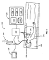
図1は、CT、MRIまたは蛍光透視画像を患者の肺の管腔網を通って標的までナビゲートするのを支援する光画像データで増補するように構成された電磁ナビゲーション(EMN)システム100を示す。そのようなENMシステムの1つは、現在コヴィディエン社によって販売されている電磁ナビゲーション気管支鏡(登録商標)システムであってもよい。EMNシステム100は、カテーテルガイドアセンブリ110、気管支鏡115、計算装置120、監視装置130、EMボード140、追跡装置160および基準センサ170を備える。気管支鏡115は、有線接続(図1に示す)または無線接続(図示せず)を介して計算装置120および監視装置130に動作可能に接続されている。
FIG. 1 illustrates an electromagnetic navigation (EMN)
気管支鏡115を患者150の口に挿入し、肺の管腔網の画像を取得する。EMNシステム100では、患者150の管腔網の末梢へのアクセスを達成するためにカテーテルガイドアセンブリ110を気管支鏡115に挿入する。カテーテルガイドアセンブリ110は、遠位先端にEMセンサ265(図2B)を備えた位置特定可能ガイドカテーテル(LG)220が挿入される伸長式作業チャネル(EWC)230を備えていてもよい。以下により詳細に説明するように、EWC230、LG220およびEMセンサ255を使用して肺の管腔網を通してナビゲートする。
A
ラップトップ、デスクトップ、タブレットまたは他の同様の計算装置などの計算装置120は、表示装置122、1つ以上のプロセッサ124、メモリ126、ネットワークカード128および入力装置129を備える。またEMNシステム100は、複数の計算装置を備えていてもよく、ここで複数の計算装置は、計画、治療、可視化のため、あるいは医療手術に適した方法で臨床医を支援するために用いられる。表示装置122は、表示装置122を入力装置および出力装置の両方として機能させることができるタッチセンサ式および/または音声作動式であってもよい。表示装置122は、肺疾患の症状を示す肺の一部を特定し、かつその位置を突き止めるために、肺の2次元(2D)画像または3次元(3D)モデルを表示してもよい。そのような画像およびモデルの生成については以下により詳細に説明する。表示装置122は、治療される標的を選択、追加および削除するためのオプションおよび肺の可視化のために設定可能な項目をさらに表示してもよい。一態様では、表示装置122は、肺の2D画像または3Dモデルに基づき、肺の管腔網内のカテーテルガイドアセンブリ110の位置も表示してもよい。説明(本開示の範囲を限定するものではない)を容易にするために3Dモデルについて以下に詳細に説明するが、当業者であれば2Dモデルおよび画像を用いて同様の機能およびタスクを達成できることが分かるであろう。
A
1つ以上のプロセッサ124はコンピュータ実行可能命令を実行する。プロセッサ124は、肺の3Dモデルを表示装置122に表示することできるように画像処理機能を行ってもよい。実施形態では、1つ以上のプロセッサ124が他のプログラムに利用可能になり得るように、計算装置120は、画像処理機能のみを行う別個のグラフィックアクセラレータ(図示せず)をさらに備えていてもよい。メモリ126はデータおよびプログラムを格納する。例えば、データは3Dモデルの画像データであってもよく、あるいは患者の医療記録、処方および/または患者の疾患歴などの任意の他の関連データであってもよい。
One or
メモリ126に格納されるプログラムの一種は3Dモデル/経路計画ソフトウェアモジュール(計画ソフトウェア)である。3Dモデル生成/経路計画ソフトウェアの例は、現在コヴィディエン社によって販売されているILOGIC(登録商標)計画ソフトウェアパッケージであってもよい。例えばCT画像データセット(または他の画像診断法による画像データセット)から得られた、典型的には「医用におけるデジタル画像と通信(DICOM:Digital Imaging and COmmunications in Medicine)」フォーマットである患者の画像データを計画ソフトウェアにインポートすると、気管支樹の3Dモデルが生成される。一態様では、CT画像診断法、磁気共鳴画像(MRI)法、機能的MRI法、X線法および/または任意の他の画像診断法によって画像診断を行ってもよい。3Dモデルを生成するために、計画ソフトウェアは領域分割、表面レンダリングおよび/または体積レンダリングを用いる。次いで、計画ソフトウェアにより、3Dモデルを元の画像データを見直すために一般に使用される軸方向表示、冠状方向表示および矢状方向表示を含む多くの異なる表示にスライスしたり操作したりすることができる。これらの異なる表示によりユーザは画像データを全て見直し、画像内の潜在的標的を特定することができる。
One type of program stored in the
標的を特定したら、当該ソフトウェアは経路計画モジュールを開始する。経路計画モジュールは標的へのアクセスを達成するための経路計画を作成し、その経路計画は標的の位置を正確に示し、かつEMNシステム100、特にEWC230およびLG220と共にカテーテルガイドアセンブリ110を用いて標的に到達することができるように標的の座標を特定する。経路計画モジュールは、臨床医を一連の工程を通して案内して、エクスポートのため、および患者150の体内の標的へのナビゲーション中に後で使用するために経路計画を作成する。臨床医という用語は、医師、外科医、看護師、医療助手または医療処置の計画、実行、監視および/または監督に関わる経路計画モジュールのあらゆるユーザを含んでもよい。
After identifying the target, the software starts the route planning module. The route planning module creates a route plan to achieve access to the target, which route plan accurately locates the target and targets the target using the
これらのプロセスおよび経路計画モジュールの詳細は、2014年8月11日に出願された「治療手順計画システムおよび方法(Treatment procedure planning system and method)」という発明の名称の本発明の譲受人に譲渡された米国特許出願第62/035,863号、および2013年6月21日に出願された「経路計画システムおよび方法(Pathway planning system and method)」という発明の名称の米国特許出願第13/838,805号に記載されており、それらの各開示内容全体が参照により本開示に組み込まれる。そのような経路計画モジュールにより、臨床医はCT画像データセットの個々のスライスを見て1つ以上の標的を特定することができる。これらの標的は、例えば、肺疾患により肺機能が損なわれている組織の作用に影響を与える病変部または神経の位置であってもよい。 Details of these process and route planning modules have been transferred to the transferee of the invention under the title of the invention "Treatment procedure planning system and method" filed on August 11, 2014. US Patent Application No. 62 / 035,863, and US Patent Application No. 13/838, entitled "Pathway planning system and method" filed June 21, 2013, It is described in No. 805, and the entire contents of each of those disclosures are incorporated herein by reference. Such a routing module allows clinicians to look at individual slices of CT image datasets to identify one or more targets. These targets may be, for example, the location of lesions or nerves that affect the action of tissues whose lung function is impaired by lung disease.
メモリ126は、臨床医に案内を行い、かつ3Dモデルおよび3Dモデルから得られた2D画像上の計画された経路の表示を行うための、EMNシステム100とインタフェースで接続するナビゲーション/手順ソフトウェアを格納していてもよい。そのようなナビゲーションソフトウェアの例は、コヴィディエン社によって販売されているILOGIC(登録商標)ナビゲーション/手順ソフトウェアパッケージである。実際には、EM場発生装置145により生じたEM場における患者150の位置を、3Dモデルおよび3Dモデルから得られた2D画像に登録しなければならない。そのような登録は手動であっても自動であってもよく、コヴィディエン社によって2014年7月2日に出願された「肺の中をナビゲートするためのシステムおよび方法(System and method for navigating within the lung)」という発明の名称の本開示と同時に出願され、かつ本発明の譲受人に譲渡された米国特許出願第62/020,240号に詳細に記載されている。
The
図1に示すように、EMボード140は、患者が横たわる平らな表面を提供するように構成されており、EM場発生装置145を備える。患者150がEMボード140に横たわると、EM場発生装置145は、患者150の一部を取り囲むのに十分なEM場を発生する。LG220の端部にあるEMセンサ265を使用して、EM場発生装置145により生じたEM場におけるEMセンサ265の位置を決定する。
As shown in FIG. 1, the
一実施形態では、EMボード140は、患者150の胸部に位置する基準センサ170に動作可能に接続されるように構成されていてもよい。基準センサ170は患者150が息を吸い込む間は胸部に従って上に移動し、患者150が息を吐いている間は胸部に従って下に移動する。患者150の呼吸パターンを認識することができるように、EM場における患者150の胸部の動きは基準センサ170によって取得されて、追跡装置160に送信される。追跡装置160はEMセンサ265の出力も受信し、両方の出力を組み合わせ、EMセンサ265の位置特定のために呼吸パターンを補正する。このように、EMセンサ265の補正された位置を肺の3Dモデルと同期させることができるように、EMセンサ265によって特定された位置を補正してもよい。患者150を3Dモデルに登録すると、EWC230および特にLG220の位置をEM場発生機145により生じたEM場内で追跡することができ、LG220の位置をナビゲーション/手順ソフトウェアの3Dモデルまたは2D画像内に示すことができる。
In one embodiment, the
図2Aは、図1のカテーテルガイドアセンブリ110の一実施形態を示す。カテーテルガイドアセンブリ110は制御ハンドル210を備える。制御ハンドル210は、伸長式作業チャネル(EWC)230またはEWC230に挿入される位置特定ガイドカテーテル(LG)220を選択的かつ機械的に操縦、回転および前進させるためのアクチュエータおよびセレクター機序を有し、これはLG220の遠位先端260が制御ハンドル210の移動に従った方向を向くことを意味している。固定機序225はEWC230およびLG220を互いに固定する。本開示で使用可能なカテーテルガイドアセンブリは、スーパーディメンション(superDimension)(登録商標)手順キットおよびEDGE(商標)手順キットという名称でコヴィディエン社によって現在市販および販売されているものであってもよい。カテーテルガイドアセンブリのより詳細な説明は、Ladtkowらにより2013年3月15日に出願された共同所有の米国特許出願第13/836,203号および米国特許第7,233,820号にあり、その開示内容全体が参照により本明細書に組み込まれる。
FIG. 2A shows one embodiment of the
図2Bは、図2AのEWC230の遠位端250の拡大図である。光源255はEWC230の遠位端250に位置している。EMセンサ265は、EWC230の遠位端250を超えて延在している状態で示されているLG220の遠位先端260に位置している。上に簡単に説明したように、EMセンサ265はEM場発生装置145により生じたEM場を感知する。感知されたEM場を使用してEM場の座標系に従い、EMセンサ265の位置を特定する。追跡装置160によってEMセンサ265の位置が決定されると、計算装置120はEMセンサ265の位置を肺の3Dモデルと比較し、EMセンサ265の位置を3Dモデルの座標系の中に登録する。
FIG. 2B is an enlarged view of the
例えば、EMセンサ265が気管への入口の近くにある場合、EMセンサ265はEM場を感知し、次いで、EMセンサ265の位置がナビゲーション/手順ソフトウェアの3Dモデルおよび2D画像の対応する位置に示されるように、EMセンサ265の位置は3Dモデルの気管部分と比較される。次いで、EMセンサ265を気管を通して気管支樹が分岐している位置までさらに挿入すると、EMセンサ265が気管の入口から分岐位置まで移動した距離は、ナビゲーション/手順ソフトウェアの3Dモデルおよび2D画像内の対応する距離に一致するように縮尺される。具体的には、EMセンサ265が気管に沿って移動すると、その距離がEM場の座標系に従って測定される。EM場の座標系は3Dモデルの座標系と異なるため、EM場の座標系を3Dモデルの座標系に一致させるための縮尺係数が存在する。従って、縮尺係数をEMセンサ265が移動した距離に掛けて、EM場の座標系を3Dモデルの座標系と同期させる。このように、EM場の座標系をナビゲーション/手順ソフトウェアの3Dモデルおよび2D画像と同期させてもよい。あるいは、他の好適な方法を用いてEM場の座標系を3Dモデルの座標系と同期させてもよい。
For example, if the
上述のように、3Dモデルでは、カテーテルガイドアセンブリ110のEWC230を標的に案内するのに十分な解像度を得ることができないが、これは3Dモデルが不鮮明になったりEWC230が特定の地点に接近すると管腔網を認識しなくなったりすることを意味する。例えば、CTスキャン装置によって1mmの厚さおよび1cmの間隔でCTスキャン画像が撮影された場合、対応する3Dモデルおよび/または経路計画は、1cm未満の大きさの標的の全体像または直径が1cm未満の管腔網の部分を示すことができない。従って、CTスキャン画像が十分に詳細に示すことができない特定の大きさに満たない大きさの標的および/または終末気管支分岐部を発見および/または特定するために別の画像診断法が必要である。この目的のために、メモリ126は、以下に詳細に説明するように、カテーテルガイドアセンブリ110に関連する画像診断法によって取得された画像データを処理および変換することができる別のプログラムも格納する。この画像データをそのような標的および終末気管支分岐部を特定するのに十分な解像度を有する可視画像に変換してもよく、あるいは、より高い解像度を得、かつCTスキャンで欠けていたデータを埋める目的で、それらを組み込んで使用してCTスキャンからのデータを更新してもよい。
As mentioned above, the 3D model does not provide sufficient resolution to guide the EWC230 of the
そのような画像診断法の1つが図2Bに示されており、ここでは光源255および光受信機257はEWC230の遠位端の近くに示されている。当業者であれば、光源255および光受信機257もLG220上に形成することができ、あるいは本開示の範囲から逸脱することなく、2つ以上の各光源および光受信機を用いてもよいことが分かるであろう。光源255は気道に対して可視光を発し、光受信機257は気道の組織から反射および/または散乱された可視光を受信する。一般に、可視光は、400ナノメートル(nm)〜700nmの範囲の電磁波を含む。
One such diagnostic imaging method is shown in FIG. 2B, where the
光源255は、その近位端で発光ダイオード(LED)、白熱電球、蛍光電球または可視光を発生するあらゆる好適な光源に接続する光ファイバーの遠位端(図示せず)であってもよい。同様に、光受信機267は、計算装置120上に存在する画像診断ハードウェアおよびソフトウェアに接続する光ファイバーの遠位端であってもよい。画像診断ハードウェアは、光電池、フォトレジスタ、フォトダイオード、フォトトランジスタ、カラー電荷結合素子、共焦点ミニプローブ、または400nm〜700nmの範囲の波長を有する光を検出するのに適したあらゆる装置を備えていてもよい。これらの光ファイバーはEWC230内に位置していても、EWC230の外側に取り付けられていても、EWC230の内腔に配置されていてもよい。
The
異なる種類の肺組織は、特定の周波数で異なるパターンの可視光の吸収、散乱および反射を有する。これらのパターンを予測アルゴリズムを用いて分光分析で確定的に使用して、組織の種類を特定してもよい。また、これらのパターンを使用して組織の密度、組織の病状および治療の十分性を確認し、かつ光受信機267が治療される標的の位置にあるか否かを判定してもよい。白色光は光の全ての可視領域を含むため、分光分析のために白色光を使用してもよい。一態様では、光画像診断法は光干渉断層撮影法であってもよい。実施形態では、光源265および光受信機267をEWC230の周囲に形成してもよく、それらにより気管支樹の気道の放射状図が生成され、かつ気道の光学マップが生成される。
Different types of lung tissue have different patterns of absorption, scattering and reflection of visible light at specific frequencies. These patterns may be definitively used in spectroscopic analysis using predictive algorithms to identify tissue types. These patterns may also be used to confirm tissue density, tissue pathology and therapeutic adequacy, and to determine if the optical receiver 267 is in the position of the target to be treated. Since white light includes the entire visible region of light, white light may be used for spectroscopic analysis. In one aspect, the optical imaging method may be a light interference tomography method. In embodiments, a
図5Aは気管支粘膜の反射分光測定結果500を示す。垂直軸は単位を含まない0〜1.5の範囲の正規化された反射率を表し、水平軸は400nm〜900nmの範囲の波長を表す。反射スペクトル信号グラフ510には600nm近くに窪み520があるが、それは血中のヘモグロビンがその周波数で光を吸収するからである。反射スペクトル信号グラフ510は、正常な気管支粘膜の反射パターンまたは吸収パターンを示してもよい。
FIG. 5A shows the reflection
図5Bは、正常な気管支粘膜および悪性の気管支粘膜のための別の反射スペクトル信号グラフ550の例を示す。図5Aに記載するように、垂直軸は単位を含まない反射パターンを表し、水平軸は300nm〜1,000nmの範囲の波長を表す。反射スペクトル信号グラフ560は正常な粘膜の反射パターンを示し、反射スペクトル信号グラフ570は悪性の粘膜の反射パターンを示す。図5Bに見られるように、悪性の粘膜は600nm近くに正常な粘膜よりも急勾配の窪み580を有する。これは、悪性の粘膜がより多くの血液体積を有するために、その周波数でより多くの光を吸収し、かつより少ない光を反射するより多くのヘモグロビンが病変部に存在していることを証明している。
FIG. 5B shows an example of another reflection
白色光が光源255から発せられると、正常な粘膜および悪性の粘膜は血液含有量に基づき異なるパターンの反射スペクトルを有する。しかし、これらのパターンの反射スペクトルはヒトの目では容易に識別することができない。従って、光受信機257が反射光を感知すると、計算装置120は反射光に対して分光分析を行い、組織の種類もしくは密度を特定し、かつ/またはその組織が悪性であるか否かを判定する。計算装置120は、3Dモデルまたはそこから得られた2D画像を分光分析データで増補してもよい。
When white light is emitted from the
本開示の一態様では、蛍光を使用して、可視光を用いる分光法により標的を特定してもよい。CTまたはMRIスキャンにより標的を特定したら、蛍光または自家蛍光染料のいずれか一方を用いてその標的を染色してもよい。蛍光染料の場合、光源255が蛍光染色された病変部に対して光を発すると、蛍光染料は、光受信機257で受信することができ、かつ他の染色されていない肺組織の応答とは異なるように検出することができる特定の周波数応答を放出する。同様に、光源255を必要とすることはないが、自家蛍光染料は特定の周波数で絶えず信号を発しており、これらの信号は光受信機257で受信および検出することができる。どちらの場合も、応答を処理して計算装置120の表示装置に表示することができるため、分光分析を必要とすることなく標的を可視化することができる。
In one aspect of the disclosure, fluorescence may be used to identify the target by spectroscopy using visible light. Once the target has been identified by CT or MRI scan, the target may be stained with either fluorescent or autofluorescent dye. In the case of fluorescent dyes, when the
実施形態では、治療を行って気管支樹の異常組織を治療する場合、治療に沿って蛍光色を変化させてもよい。言い換えると、治療が完了すると、蛍光色は消えるか所定の色に変化してもよい。従って、臨床医は標的の蛍光色を調べることにより、標的の治療が完了したか否か、あるいは別の治療を行うべきか否かを判定してもよい。一般に、治療を行った場合、別の組のCTまたはMRIスキャンを行って治療のレベルを確認する必要がある。しかし、光検出ハードウェアおよびソフトウェアと組み合わせた光受信機257は異常組織の蛍光色を確認することができるため、別のCTスキャンを行わずにその場で治療のレベルを確認してもよい。
In the embodiment, when the treatment is performed to treat the abnormal tissue of the bronchial tree, the fluorescent color may be changed along with the treatment. In other words, when the treatment is complete, the fluorescent color may disappear or change to a given color. Therefore, the clinician may examine the fluorescent color of the target to determine if the treatment for the target has been completed or if another treatment should be given. Generally, when treatment is given, another set of CT or MRI scans should be performed to confirm the level of treatment. However, since the
図2Bに示すように、光源255および光受信機257はある距離DOFFだけEMセンサ265から離れている。この距離DOFFは、臨床医がナビゲーション/手順ソフトウェアにコード化するか測定および設定してもよく、あるいは光源255およびEMセンサ265が感知してもよい。計算装置120は距離DOFFを使用して、可視光データ画像の3Dモデルまたはそこから得られた2D画像への組み込みを調整する。例えば、EMセンサ265がLG220の遠位先端260に位置し、光受信機257がEWC230の遠位端250またはその周囲に位置し、かつそれらが互いから1cmの距離だけ離れている場合、可視光データは、EM場の座標系において1cmに相当する3Dモデルの座標系における距離だけ位置をずらして3Dモデルまたはそこから得られた2D画像の中に統合される。
As shown in FIG. 2B, the
経路計画に従ったカテーテルガイドアセンブリ110の操作によりEWC230およびLG220が標的に到達すると、EMセンサ265は標的におけるその位置を確認し、臨床医は受信機257によって生成された可視画像を見て標的におけるその位置を目で確認してもよい。LGカテーテル220をカテーテルガイドアセンブリ110から取り出してもよく、生検具をEWC230の中に標的まで挿入して疾患の確認のために標的試料を採取してもよい。固定具を用いてEWC230を標的に固定してもよい。さらに、焼灼カテーテルなどの治療具をEWC230を通して標的の中に挿入してもよい。光源255および光受信機257を使用して、治療具を取り囲んでいる組織から反射および/または散乱され、かつ光受信機257によって受信された光データを目で見ることにより、あるいは標的の分光画像を正常組織または罹患組織の画像と臨床的に比較することにより、治療具が標的の位置にあることを確認してもよい。
When the EWC230 and LG220 reach the target by manipulating the
呼吸困難のいくつかの原因は、気道内の粘液および/または異物に関連している。光受信機257によって感知された可視光データは、気道内の粘液および異物を示してもよい。従って、経路計画に従い標的まで移動している間にこれらが発見された場合、吸引具などの治療具を使用して肺の気道内の粘液または異物を除去する。
Some causes of dyspnea are associated with mucus and / or foreign bodies in the airways. Visible light data sensed by the
実施形態では、治療前工程において、標的の位置をマークするために1つ以上のマーカーをEWC230の中に配置することができる。このマーカーは、本開示のEMナビゲーション機能が有効になり得ない場合、特にLG220およびEMセンサ265の取り出し後に、所望の位置へのナビゲーションおよびEWC230の配置の確認を支援することができる。このマーカーにより、臨床医は標的の治療後に標的を再診し、かつさらなる試料を採取することができるようになる。このマーカーは、基準マーカー、蛍光染料またはFLUOROGOLD(登録商標)であってもよい。蛍光染料マーカーの場合、上記のとおり光受信機257で受信された光データを使用して治療の十分性を判定したり、標的の正確な位置に関するより高い鮮明性を得たりしてもよい。当業者は、本開示の範囲から逸脱することなく、標的の位置をマークするために他のマーカーを用いてもよい。
In the embodiment, one or more markers can be placed in the
図3は、肺と共に患者の気管支樹および気管の3Dモデル300を示す。3Dモデル300は、図3に示すように臨床医が特定の臓器または対象の臓器の部分を選択的に見ることができるように、臓器の大部分の情報を含んでいてもよい。この場合、これらの選択された臓器は、右葉310、左葉320、気管330および気管支樹340を含む肺である。右葉310は3つの下位の葉、すなわち上葉312、中葉314および下葉316を有し、左葉320は2つの下位の葉、すなわち上葉322および下葉324を有する。
FIG. 3 shows a
気管330は、咽頭および喉頭を肺310および320に繋げる管である。気管330の下端では左および右主気管支342に分かれる。また、主気管支342の下端では葉気管支344に分かれる。主気管支342の外周は葉気管支344の外周よりも大きい。同じように、葉気管支344の下端では区域気管支346に分かれ、区域気管支346の下端では終末細気管支348に分かれる。主気管支342、葉気管支344および区域気管支346は軟骨板によって支えられている。しかし、区域気管支346の大きさが段々と小さくなると軟骨板は存在しなくなり、外壁は平滑筋で占められる。終末細気管支348の外壁も平滑筋で占められている。
The
罹患細胞または癌性細胞あるいは簡単に言うと標的は、あらゆる気管支樹、主気管支342、葉気管支344、区域気管支346および終末細気管支348上に存在し得る。標的がどこに位置していても、標的が小さすぎてCT画像診断法により検出できない場合でさえ、光源255および光受信機257を備えたEWC230が別の標的に向かって肺の管腔網を通ってナビゲートしている間に、本明細書に記載されている光インタロゲーション方法によって標的を検出することができる。光データにより、患者の体内の標的の位置を検出および特定する際により高い特異性およびより高い正確性が得られる。少なくとも1つの実施形態によれば、光源255および光受信機257はEWC230を取り囲み、それらを用いて、上記経路計画および光データに従い、かつ経路に沿って肺の画像データをさらに精細化する。この光データをCTスキャン画像および/または3Dモデル300に登録して、標的の検出、位置および大きさに関してより高い鮮明性を得てもよい。また、例えばこの光データを診断的に使用して、臨床医が全てのそれらしい標的が特定されていること、あるいは治療後に完全に治療されていることを確認するのを支援してもよい。
Affected or cancerous cells or, in short, targets can be on any bronchial tree,
さらに、光受信機257が光画像データを取得すると、そのデータは無線または有線接続を介して計算装置120に転送される。光技術によって取得された画像データはまだ臨床医によって容易に見ることできる状態ではない。計算装置120は光画像データを、臨床医が組織の種類を特定したり、病状を診断したり、治療のレベルを決定したりすることができる画像に処理および変換する。
Further, when the
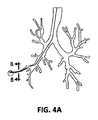
図4Aは、3Dモデルの気管支樹の平面図すなわち図3の気管支樹などの肺のスライス画像と標的までの経路計画とを示す。経路計画は、標的が図3の終末細気管支の下側左端の先端に位置している場合に肺の管腔網を通って標的に到着する方法を示す。 FIG. 4A shows a plan view of the bronchial tree of the 3D model, that is, a slice image of the lung such as the bronchial tree of FIG. 3 and a route plan to the target. The route planning shows how to reach the target through the luminal network of the lung when the target is located at the tip of the lower left end of the terminal bronchiole of FIG.
図4Bは、図4Aの断面線B−Bに沿って切断された終末細気管支の拡大横断面図である。終末細気管支は平滑筋405によって囲まれている。神経410および静脈415は平滑筋405の外壁に位置している。符号412は、気道内の腫れた平滑筋、粘液または異物を表す。光画像診断法では上記のように、終末細気管支に向かう気道の内部情報までも得られるため、異物、粘液または腫れた平滑筋を目で見ることができたり平滑筋405上の細い神経410および静脈415さえも検出および特定したりすることができる。
FIG. 4B is an enlarged cross-sectional view of the terminal bronchioles cut along the cross-sectional line BB of FIG. 4A. The terminal bronchiole is surrounded by
図4Cは、経路計画に従いカテーテルガイドアセンブリが患者の天然の開口部(例えば口)から標的まで肺の中に挿入された状態の気管支鏡420を示す。気管支鏡420が肺の特定の位置に到達すると、気管支鏡420はサイズ制限により、動けなくなって気管支樹内をさらに進むことができなくなる。そこで、上記のようにカテーテルガイドアセンブリのEWC430を使用して、経路計画に従い標的450まで管腔網をナビゲートしてもよい。EWC430は標的450に到達するのに十分な程に小さくて細い。図4Dは、図4Cの丸で囲まれた領域の拡大詳細図を示し、ここでは、位置特定可能ガイド(LG)はEWC430の遠位先端から突き出ていてもよく、肺の終末細気管支に位置する標的450まで管腔網をナビゲートする。
FIG. 4C shows the
図6Aは、可視光技術を用いて肺組織を可視化する方法600のフローチャートである。方法600は、肺の3Dモデルおよび標的までの経路計画を図1の計算装置120などのコンピュータに格納されたナビゲーション/手順ソフトウェアにインポートする工程605で開始する。
FIG. 6A is a flowchart of a
工程610では、図1に示すように、EMボード140のEM場発生装置145によりEM場を発生させる。工程615では、EMセンサ265、光源255および光受信機257を天然の開口部または切開部から肺の中に挿入する。一態様では、EMセンサ265および光源255および光受信機257はある距離だけ離れてEWC230上に位置していてもよく、あるいは異なる場所に位置していてもよい。例えば、EMセンサ265はLG220の遠位先端260またはその周囲に位置していてもよく、光源255および光受信機257はEWC230の遠位端250またはその周囲に位置していてもよく、あるいはそれらは逆であってもよい。
In
工程620では、EMセンサ265はEM場を感知し、感知された結果は計算装置120に送信される。感知された結果を使用してEM場の座標系におけるEMセンサ265の位置を計算する。位置を計算したら、計算装置120はEMセンサ265の位置を、3Dモデルまたはそこから得られた2D画像および経路計画と比較する。一態様では、計算装置120に送信する前に、EMセンサ265の位置を、追跡装置160および基準センサ170により検出することができる患者の呼吸パターンに従って補正してもよい。従って、患者が息を吸ったり吐いたりする間にEMセンサ265の位置が3Dモデルの座標系において異なることはない。
In
工程625では、EMセンサ265の位置を3Dモデルおよびそこから得られた2D画像と同期させる。この位置は3Dモデルの開始位置すなわち3Dモデルの気管の入口であってもよい。この位置を同期させたとしても、EMセンサ265の実際の移動はここではまだ3Dモデルに同期されていない。
In
EMセンサ265は、ある距離だけ(例えば、気管の入口から気管の底にある分岐点まで)移動する。EMセンサ265がEM場の感知を開始した後、この距離をEM場の座標系において測定してもよい。工程630では、EM場の座標系によるEMセンサ265の移動距離を、縮尺された距離が3Dモデルの座標系に一致するように縮尺してもよい。この工程の後に、EMセンサ265の位置および移動を3Dモデルに実質的にマッピングする。これは3Dモデルおよびそこから得られた2D画像への患者の同期すなわち登録である。
The
工程635では、EMセンサ265、LG220およびEWC230は経路計画に従って標的まで肺の管腔網をナビゲートする。工程640では、EMセンサ265が標的に到達したか否かを判定する。EMセンサ265が標的に到達していないと判定された場合、経路計画に従い標的に到達するまでナビゲーション工程635を継続する。
In
実施形態では、工程640において標的に到達していると判定された場合、工程645を行い、本明細書に記載されている光技術で標的をインタロゲートしてその位置を確認してもよい。さらに、治療後にインタロゲーションを用いて治療の十分性を確保してもよい。以下の図6Cでは工程645をさらに詳細に説明する。
In the embodiment, if it is determined in
図6Bは、標的へのナビゲーションの詳細な工程すなわち図6Aの方法600の工程635を示す。工程650では、EWC230の遠位端が経路計画に従って標的までナビゲートする間に、可視光を光源255から発して光受信機257で受信する。工程655では、光受信機257は肺の気道から反射された可視光を受信し、それを計算装置120に送信し、次いで計算装置120は工程660で予測アルゴリズムを用いて反射された可視光に対して分光分析を行う。反射光は振幅および送信から受信までの遅延時間などの情報を有する。計算装置120はその情報を処理して肺組織の密度または種類を決定し、かつ/またはCTスキャン画像内に新しい標的(すなわち治療される罹患細胞または癌性細胞、気道内の粘液または異物)が発見されていないか否かを判定する。
FIG. 6B shows the detailed steps of navigating to the target,
工程665では、標的までの経路計画に沿って新しい標的が存在するか否かを判定する。新しい標的が存在すると判定された場合、工程670では新しい標的を特定して、後での治療のために3Dモデルに登録する。工程675では、標的までの経路計画の一部である新しい標的までの経路も新しい標的までの経路計画として保存する。次いで、方法635は工程665に戻って別の新しい標的が存在するか否かを確認する。
In
工程665において新しい標的が存在しないと判定された場合、計算装置120は、処理された反射光に基づき画像を生成してもよい。可視光の波長の大部分は肺組織の気道の内面から反射されるため、生成された画像は気管支樹の内部を示す。生成された画像は、気管支樹の内部に存在する罹患細胞、癌性細胞、粘液または異物も示す。一態様では、治療装置が治療目的で標的に貫通した場合、生成された画像は治療装置が標的の位置にあるか否かを示すことができる。
If it is determined in
工程685では、EMセンサ265の位置ならびにEMセンサ265と光源255および光受信機257との離間距離DOFFに基づき、生成された画像を3Dモデルまたはそこから得られた2D画像に統合する。実施形態では、CTスキャン画像のより低い解像度部分をより高い解像度画像(すなわち生成された可視画像)で置き換えることができるように、生成された画像をCTスキャン画像に上書きしてもよく、光画像データを選択的に融合して複合画像データセットを作成してもよく、あるいはこれらのデータをCT画像データに組み込んでもよい。工程690では、計算装置は、3Dモデルを含む生成された画像すなわち簡単に言うと統合された3Dモデルを表示する。図6Aの方法600に図示するように、これらのナビゲーション工程650〜690を標的に到達するまで繰り返す。
In
一実施形態では、本明細書に記載されている光技術を用いる可視化すなわちインタロゲーションを使用して治療の十分性を判定してもよい。一般に、標的に対して1回の治療を行った場合、標的の大きさ、密度および水分を含む標的の属性は変化する。従って、治療が完了したか否かを確認するために、標的の属性を治療前に取得した同様の測定値と確認および比較しなければならない。一実施形態では、十分な治療後に色を変えるか消える蛍光染料の使用と組み合わせた光インタロゲーションを使用して治療のレベルを決定してもよい。図6Cは、治療の十分性を確認する方法のフローチャートである。工程705では、LG220およびEMセンサ265の取り出し後に、焼灼カテーテルなどの治療装置をEWC230に挿入する。工程710では、上記のように組織をインタロゲートし、治療装置が標的の位置にあるか否かを判定する。
In one embodiment, visualization or intervention using the optical techniques described herein may be used to determine the adequacy of treatment. In general, a single treatment of a target changes the attributes of the target, including the size, density and water content of the target. Therefore, the attributes of the target must be confirmed and compared with similar measurements taken prior to treatment to confirm whether treatment is complete. In one embodiment, the level of treatment may be determined using optical interrogation in combination with the use of fluorescent dyes that change or disappear after sufficient treatment. FIG. 6C is a flowchart of a method for confirming the adequacy of treatment. In
治療装置が標的の位置にないと判定された場合、工程715では治療装置を多少挿入または後退させてその位置を調整する。次いで、工程710では治療装置の位置を再び確認する。工程710において治療装置が標的の位置にあると判定された場合、治療装置で標的を治療する。
If it is determined that the treatment device is not in the target position,
別の実施形態では、図6Cの工程705〜715と同様の工程を生検に適用してもよい。生検具を挿入して標的の試料を採取したら、光源255および光受信機257を使用して生検具が正しい標的の位置にあるか否かを確認する。生検具が正しい場所にあると判定された場合、生検具で試料を採取する。生検具が標的の位置にないと判定された場合、生検具を調整して標的に正確に到達させてもよい。
In another embodiment, steps similar to steps 705-715 in FIG. 6C may be applied to the biopsy. After inserting the biopsy tool and collecting the target sample, the
工程720では、治療装置で標的を治療する。次いで治療への適用後に、光源255は可視光を発して標的をインタロゲートし、光受信機257は反射された可視光を受信して、工程725で標的の属性(例えば、大きさ、色など)を決定し、工程730でそれらの属性を閾値と比較する。ここで閾値は、疾患の種類に基づいて予め定められていてもよく、疾患が完全に治療されていることを示してもよい。
In
標的の色が所定の色と等しくなく、かつ標的の密度が所定の密度よりも大きいと判定された場合、計算装置120は工程735で、治療が不完全であることを表示画面にそのような通知を表示して臨床医に知らせる。所定の密度は、正常組織の密度に基づき予め定められていてもよい。次いで、方法645は、別の治療のために工程720に戻る。これらの工程720〜735を治療が完了するまで繰り返す。
If it is determined that the target color is not equal to the predetermined color and the target density is greater than the predetermined density, the
工程730において、蛍光染料を用いた場合に治療された標的の色が所望の色の変化に達していないと判定されたか、あるいは標的の密度が所定の密度以下であると判定された場合、計算装置120は工程740で、治療が完了したことを表示して臨床医に治療の完了を知らせ、治療の十分性を確認する方法645は終了する。
Calculated if in
実施形態では、工程730により気道が十分に広くなっているか否かを判定してもよい。一般に喘息は狭い気道によって引き起こされる。気道は狭くなったり、詰まったり、粘液、異物もしくは腫れた平滑組織によって制限されたりする。粘液または異物を取り除くか腫れた平滑組織を緩和させる治療により気道を広げてもよい。本実施形態では、気道の大きさを治療前の気道の大きさと比較する。他の確認工程を同様に適用してもよい。 In an embodiment, step 730 may determine if the airway is wide enough. Asthma is generally caused by narrow airways. The airways are narrowed, clogged, and restricted by mucus, foreign bodies, or swollen smooth tissue. The airways may be widened with treatments that remove mucus or foreign bodies or relieve swollen smooth tissue. In this embodiment, the size of the airway is compared with the size of the airway before treatment. Other confirmation steps may be applied in the same manner.
別の実施形態では、監視装置130および/または計算装置120は、臨床医に状況を知らせるカラーコードを表示装置に表示してもよい。その状況はカテーテルガイドアセンブリ110のEWC230の位置に基づいていてもよい。その状況は、カテーテルガイドアセンブリ110のEWC230が標的内でない位置、標的の位置、または健康な組織に隣接する位置にあるか否か、および標的の治療が完了したか否かを示してもよい。例えば、赤色はEWC230が標的内でない位置にあることを示し、緑色はEWC230が標的の位置にあることを示し、黄色はEWC230が健康な組織に隣接していることを示し、かつ橙黄色は治療が完了したことを示すようにカラーコードを使用してもよい。但し、これは一例であって本開示の範囲を限定するものではない。当業者であれば理解するように、他の状況表示システムを用いてもよい。
In another embodiment, the
上に詳細に説明していないが、図1に関して、ネットワークインタフェース128により、他の計算装置、気管支鏡115およびカテーテルガイドアセンブリ110は互いに、有線および/または無線ネットワーク接続を介して通信することができる。図1では、気管支鏡115およびカテーテルガイドアセンブリ110は、有線接続を介して計算装置120へ/から医用画像、医療データおよび制御データを送受信してもよい。ネットワークインタフェース128が他の計算装置または気管支鏡115およびカテーテルガイドアセンブリ110に無線で接続している場合、ネットワークインタフェース128は通信のために周波数を使用するが、これは気管支鏡115またはカテーテルガイドアセンブリ110が取得した画像を送信するために使用する周波数とは異なってもよい。
Although not described in detail above, with respect to FIG. 1,
計算装置120のメモリ126は、ソリッドステート記憶装置、フラッシュメモリチップ、大容量記憶装置、テープ駆動機構、またはストレージコントローラおよび通信バスを介してプロセッサに接続されているあらゆるコンピュータ可読記憶媒体のうちの1つ以上を備えていてもよい。コンピュータ可読記憶媒体としては、コンピュータ可読命令、データ構造、プログラムモジュールまたは他のデータなどの情報の格納のための任意の方法または技術に実装される非一時的な揮発性および不揮発性の取外し可能および取外し不可能な媒体が挙げられる。例えば、コンピュータ可読記憶媒体としては、ランダムアクセスメモリ(RAM)、リードオンリーメモリ(ROM)、消去可能プログラム可能ROM(EPROM)、電気的消去可能プログラム可能ROM(EEPROM)、フラッシュメモリもしくは他のソリッドステートメモリ技術、CD−ROM、DVD、または他の光学記憶装置、磁気カセット、磁気テープ、磁気ディスク記憶装置もしくは他の磁気記憶装置、あるいは所望の情報を格納するために使用することができ、かつ計算装置120がアクセスすることができるあらゆる他の媒体が挙げられる。
The
実施形態では、表示装置122は、指を摘まんだり広げたりするなどの複数の指の動作を表示装置が受信することができるような入力装置として機能してもよい。例えば、指を摘まんだ場合は、指を摘まむ前にその指が位置している表示装置122上の表示画像の一部は縮小されてもよく、指を広げた場合は、指を広げる前にその指が位置している表示装置122上の肺の画像の一部は拡大されてもよい。あるいは、複数の指で一緒に表示装置122を一方向にスワイプした場合は、スワイプしている方向および回転量がスワイプ動作の距離および/または速度に比例するように表示画像を同じ方向に回転させてもよい。入力装置129を用いてこれらの機能を実行してもよい。
In the embodiment, the
データまたは設定値などの制御情報あるいはテキスト情報を入力するために入力装置129を使用する。入力装置129としては、キーボード、マウス、スキャン装置または他のデータ入力装置が挙げられる。表示画像または3Dモデルを拡大、縮小および一方向へ回転させるように操作するために、入力装置129をさらに使用してもよい。
The
監視装置130は、気管支鏡115および計算装置120に動作可能に接続されている。監視装置130は、監視装置130の設定可能な項目を設定するためのボタンおよびスイッチを備える。監視装置130は、監視装置130を入力装置および出力装置の両方として機能させることができるタッチセンサ式および/または音声作動式であってもよい。従って、ボタン、監視装置130の画面へのタッチまたは音声を用いて、監視装置130の設定可能な項目を設定、変更または調整してもよい。
The
気管支鏡115が肺の管腔網の画像を取得し、取得した画像をヒトの目で見ることができるように処理する必要がない場合、特に登録の確認で使用するために臨床医がカテーテルガイドアセンブリ110の位置が意図した場所にあるかを確認することができるように、監視装置130は取得された画像を受信して監視装置130上に表示してもよい。
If the
例示および説明のために添付の図面を参照しながら実施形態について詳細に説明してきたが、当然のことながら本発明の方法および装置は限定されるものとして解釈されるべきではない。本開示の範囲から逸脱することなく、上記実施形態に対して様々な修飾をなし得ることは当業者には明らかであろう。 Although embodiments have been described in detail with reference to the accompanying drawings for illustration and description, of course the methods and devices of the invention should not be construed as limiting. It will be apparent to those skilled in the art that various modifications can be made to the above embodiments without departing from the scope of the present disclosure.
Claims (20)
管腔網の3Dモデルおよび管腔網をナビゲートするための経路計画を格納するメモリと、
電磁(EM)場を発生するように構成されたEMボードと、
前記経路計画に従い標的に向かって患者の管腔網をナビゲートするように構成された伸長式作業チャネル(EWC)と、
前記EWCの遠位端から遠位に延在し、かつ前記EM場を感知するように構成されたEMセンサと、
前記EWCまたはその周囲に位置し、かつ光を発するように構成された光源と、
前記EWCまたはその周囲に位置し、かつ前記管腔網の気道から反射された光を感知するように構成された光受信機と、
前記反射された光を処理するように構成された計算装置であって、前記反射された光は、前記反射された光の振幅および送信から受信までの遅延時間についての情報を有し、前記計算装置は、前記管腔網の3Dモデルから生成された画像内に治療すべき対象が発見されていないか否かを判定するべく前記反射された光についての情報を処理するようにさらに構成され、前記管腔網は肺組織である、計算装置と、
前記反射された光を光データに変換し、組織の種類もしくは密度を特定し、1つ以上の血管の存在を特定し、前記光データから可視画像を生成し、前記光データを前記3Dモデルと統合するように構成されたプロセッサと、
を備える、システム。 It is a system for optical interrogation.
A memory that stores a 3D model of the lumen network and a route plan for navigating the lumen network,
An EM board configured to generate an electromagnetic (EM) field,
An extendable work channel (EWC) configured to navigate the patient's luminal network towards the target according to the pathway plan, and
An EM sensor that extends distally from the distal end of the EWC and is configured to sense the EM field.
A light source located in or around the EWC and configured to emit light,
An optical receiver located at or around the EWC and configured to sense light reflected from the airways of the luminal network.
A computing device configured to process the reflected light, the reflected light having information about the amplitude of the reflected light and the delay time from transmission to reception, said calculation. device is further configured so that the information to process for the reflected light Beku subject to be treated before Symbol tube image generated from the 3D model of the腔網determines whether undiscovered , The lumen network is lung tissue, a computer and
Converting the reflected light to the optical data, identifies the type or density of the tissue, to identify the presence of one or more vessels, to generate a visible image from the optical data, the optical data and the 3D model With a processor configured to integrate,
The system.
Applications Claiming Priority (9)
| Application Number | Priority Date | Filing Date | Title |
|---|---|---|---|
| US201361874881P | 2013-09-06 | 2013-09-06 | |
| US61/874,881 | 2013-09-06 | ||
| US201462041893P | 2014-08-26 | 2014-08-26 | |
| US201462041800P | 2014-08-26 | 2014-08-26 | |
| US62/041,800 | 2014-08-26 | ||
| US62/041,893 | 2014-08-26 | ||
| US14/469,744 | 2014-08-27 | ||
| US14/469,744 US10448861B2 (en) | 2013-09-06 | 2014-08-27 | System and method for light based lung visualization |
| PCT/US2014/053890 WO2015034916A1 (en) | 2013-09-06 | 2014-09-03 | System and method for light based lung visualization |
Publications (3)
| Publication Number | Publication Date |
|---|---|
| JP2016530023A JP2016530023A (en) | 2016-09-29 |
| JP2016530023A5 JP2016530023A5 (en) | 2017-10-05 |
| JP6799463B2 true JP6799463B2 (en) | 2020-12-16 |
Family
ID=52626224
Family Applications (2)
| Application Number | Title | Priority Date | Filing Date |
|---|---|---|---|
| JP2016540345A Active JP6799463B2 (en) | 2013-09-06 | 2014-09-03 | Optical interrogation system |
| JP2016540346A Pending JP2016530024A (en) | 2013-09-06 | 2014-09-03 | System and method for visualizing lungs using light |
Family Applications After (1)
| Application Number | Title | Priority Date | Filing Date |
|---|---|---|---|
| JP2016540346A Pending JP2016530024A (en) | 2013-09-06 | 2014-09-03 | System and method for visualizing lungs using light |
Country Status (7)
| Country | Link |
|---|---|
| US (3) | US10448861B2 (en) |
| EP (2) | EP3041397A4 (en) |
| JP (2) | JP6799463B2 (en) |
| CN (2) | CN105636502B (en) |
| AU (2) | AU2014315366B2 (en) |
| CA (2) | CA2923461A1 (en) |
| WO (2) | WO2015034916A1 (en) |
Families Citing this family (17)
| Publication number | Priority date | Publication date | Assignee | Title |
|---|---|---|---|---|
| DE102015200214A1 (en) * | 2015-01-09 | 2016-07-14 | Siemens Healthcare Gmbh | Method for communication in a magnetic resonance device and magnetic resonance device |
| US20160354012A1 (en) * | 2015-06-02 | 2016-12-08 | Cardioinsight Technologies, Inc. | Magnetic sensing to provide geometry information |
| US10986990B2 (en) | 2015-09-24 | 2021-04-27 | Covidien Lp | Marker placement |
| US10357162B1 (en) * | 2015-12-30 | 2019-07-23 | Banpil Photonics, Inc. | Imaging system for screening and diagnosis of breast cancer |
| WO2017136523A1 (en) * | 2016-02-06 | 2017-08-10 | The United States Of America As Represented By The Secretary Of The Army | Airway management device for identification of tracheal and/or esophageal tissue |
| US10470839B2 (en) * | 2016-06-02 | 2019-11-12 | Covidien Lp | Assessment of suture or staple line integrity and localization of potential tissue defects along the suture or staple line |
| CN106075688A (en) * | 2016-07-11 | 2016-11-09 | 李景 | A kind of visible multifunctional intubates leads core |
| US20180049808A1 (en) * | 2016-08-17 | 2018-02-22 | Covidien Lp | Method of using soft point features to predict breathing cycles and improve end registration |
| EP3375399B1 (en) | 2016-10-05 | 2022-05-25 | NuVasive, Inc. | Surgical navigation system |
| CN107019852B (en) * | 2017-03-14 | 2020-01-31 | 苏州大学 | Tracking device for simulating human lung tumor movement |
| US11138792B2 (en) | 2018-04-02 | 2021-10-05 | Cardioinsight Technologies, Inc. | Multi-dimensional method of fundamental solutions for reconstruction of electrophysiological activity |
| EP3801190A4 (en) * | 2018-05-30 | 2022-03-02 | Auris Health, Inc. | Systems and methods for location sensor-based branch prediction |
| US11944388B2 (en) | 2018-09-28 | 2024-04-02 | Covidien Lp | Systems and methods for magnetic interference correction |
| US20220192502A1 (en) * | 2019-04-17 | 2022-06-23 | University Of Pittsburgh - Of The Commonwealth System Of Higher Education | Endovascular orifice detection device for accurate fenestrated stent graft deployment |
| CN114340542B (en) * | 2019-08-30 | 2023-07-21 | 奥瑞斯健康公司 | Systems and methods for weight-based registration of position sensors |
| US11612440B2 (en) | 2019-09-05 | 2023-03-28 | Nuvasive, Inc. | Surgical instrument tracking devices and related methods |
| CN111513676B (en) * | 2020-04-10 | 2021-11-02 | 广州永士达医疗科技有限责任公司 | OCT equipment, device and storage medium for detecting disease period of asthma patient |
Family Cites Families (78)
| Publication number | Priority date | Publication date | Assignee | Title |
|---|---|---|---|---|
| US5129896A (en) * | 1989-11-13 | 1992-07-14 | Hasson Harrith M | Holder to facilitate use of a laser in surgical procedures |
| US5244462A (en) | 1990-03-15 | 1993-09-14 | Valleylab Inc. | Electrosurgical apparatus |
| DE69332042T2 (en) | 1992-12-18 | 2003-01-02 | Koninkl Philips Electronics Nv | Delayed positioning of relatively elastically deformed spatial images by matching surfaces |
| US5569289A (en) | 1993-06-24 | 1996-10-29 | Yoon; Inbae | Safety penetrating instrument with penetrating member and cannula moving during penetration and triggered safety member protusion |
| US5531520A (en) | 1994-09-01 | 1996-07-02 | Massachusetts Institute Of Technology | System and method of registration of three-dimensional data sets including anatomical body data |
| US7778688B2 (en) | 1999-05-18 | 2010-08-17 | MediGuide, Ltd. | System and method for delivering a stent to a selected position within a lumen |
| JP2001029490A (en) * | 1999-07-19 | 2001-02-06 | Hitachi Ltd | Combined irradiation evaluation support system |
| US6749606B2 (en) | 1999-08-05 | 2004-06-15 | Thomas Keast | Devices for creating collateral channels |
| US6379302B1 (en) | 1999-10-28 | 2002-04-30 | Surgical Navigation Technologies Inc. | Navigation information overlay onto ultrasound imagery |
| US20020007122A1 (en) * | 1999-12-15 | 2002-01-17 | Howard Kaufman | Methods of diagnosing disease |
| JP4583658B2 (en) | 2001-05-22 | 2010-11-17 | オリンパス株式会社 | Endoscope system |
| US7883471B2 (en) | 2001-09-10 | 2011-02-08 | Pulmonx Corporation | Minimally invasive determination of collateral ventilation in lungs |
| EP1482831A1 (en) * | 2002-02-12 | 2004-12-08 | Science & Engineering Associates Inc. | Cancer detection and adaptive dose optimization treatment system |
| US6711426B2 (en) * | 2002-04-09 | 2004-03-23 | Spectros Corporation | Spectroscopy illuminator with improved delivery efficiency for high optical density and reduced thermal load |
| US20070015981A1 (en) * | 2003-08-29 | 2007-01-18 | Benaron David A | Device and methods for the detection of locally-weighted tissue ischemia |
| US7998062B2 (en) * | 2004-03-29 | 2011-08-16 | Superdimension, Ltd. | Endoscope structures and techniques for navigating to a target in branched structure |
| CN1658789A (en) * | 2002-04-17 | 2005-08-24 | 超级测量有限公司 | Endoscope structures and techniques for navigating to a target in branched structure |
| JP4054222B2 (en) | 2002-06-05 | 2008-02-27 | オリンパス株式会社 | Light source device for endoscope device |
| JP4085314B2 (en) | 2002-09-10 | 2008-05-14 | 株式会社日立メディコ | Ultrasonic diagnostic equipment |
| US20060173359A1 (en) * | 2002-09-30 | 2006-08-03 | Lin Wei C | Optical apparatus for guided liver tumor treatment and methods |
| ATE433993T1 (en) * | 2003-02-26 | 2009-07-15 | Univ Johns Hopkins | MODULATORY COMPOUNDS AND METHODS FOR GLUTAMATE TRANSPORT |
| EP2316328B1 (en) * | 2003-09-15 | 2012-05-09 | Super Dimension Ltd. | Wrap-around holding device for use with bronchoscopes |
| DE10357184A1 (en) | 2003-12-08 | 2005-07-07 | Siemens Ag | Combination of different images relating to bodily region under investigation, produces display images from assembled three-dimensional fluorescence data image set |
| US7901348B2 (en) | 2003-12-12 | 2011-03-08 | University Of Washington | Catheterscope 3D guidance and interface system |
| DE10358735B4 (en) | 2003-12-15 | 2011-04-21 | Siemens Ag | Catheter device comprising a catheter, in particular an intravascular catheter |
| US8764725B2 (en) * | 2004-02-09 | 2014-07-01 | Covidien Lp | Directional anchoring mechanism, method and applications thereof |
| JP2005218760A (en) | 2004-02-09 | 2005-08-18 | Olympus Corp | Endoscopic apparatus |
| US7197354B2 (en) | 2004-06-21 | 2007-03-27 | Mediguide Ltd. | System for determining the position and orientation of a catheter |
| JP4648683B2 (en) | 2004-11-09 | 2011-03-09 | Hoya株式会社 | Endoscope system |
| WO2006076789A1 (en) * | 2005-01-24 | 2006-07-27 | Claron Technology Inc. | A bronchoscopy navigation system and method |
| AU2006201646B2 (en) | 2005-04-26 | 2011-01-06 | Biosense Webster, Inc. | Display of catheter tip with beam direction for ultrasound system |
| US7889905B2 (en) | 2005-05-23 | 2011-02-15 | The Penn State Research Foundation | Fast 3D-2D image registration method with application to continuously guided endoscopy |
| DE102005027951A1 (en) * | 2005-06-16 | 2007-01-04 | Siemens Ag | Medical system for introducing a catheter into a vessel |
| GB2427692A (en) * | 2005-06-27 | 2007-01-03 | Intelligent Sensors Plc | Non-contact life signs detector |
| US7835785B2 (en) | 2005-10-04 | 2010-11-16 | Ascension Technology Corporation | DC magnetic-based position and orientation monitoring system for tracking medical instruments |
| US20070173813A1 (en) * | 2006-01-24 | 2007-07-26 | Sherwood Services Ag | System and method for tissue sealing |
| WO2008005953A2 (en) | 2006-06-30 | 2008-01-10 | Broncus Technologies, Inc. | Airway bypass site selection and treatment planning |
| US7824328B2 (en) * | 2006-09-18 | 2010-11-02 | Stryker Corporation | Method and apparatus for tracking a surgical instrument during surgery |
| WO2008125910A2 (en) | 2006-11-10 | 2008-10-23 | Superdimension, Ltd. | Adaptive navigation technique for navigating a catheter through a body channel or cavity |
| US7831076B2 (en) | 2006-12-08 | 2010-11-09 | Biosense Webster, Inc. | Coloring electroanatomical maps to indicate ultrasound data acquisition |
| US20080167639A1 (en) * | 2007-01-08 | 2008-07-10 | Superdimension Ltd. | Methods for localized intra-body treatment of tissue |
| US8672836B2 (en) | 2007-01-31 | 2014-03-18 | The Penn State Research Foundation | Method and apparatus for continuous guidance of endoscopy |
| US8690864B2 (en) * | 2007-03-09 | 2014-04-08 | Covidien Lp | System and method for controlling tissue treatment |
| EP2117436A4 (en) | 2007-03-12 | 2011-03-02 | David Tolkowsky | Devices and methods for performing medical procedures in tree-like luminal structures |
| GB0708567D0 (en) | 2007-05-03 | 2007-06-13 | Univ Manchester | Imaging technique |
| US8428690B2 (en) | 2007-05-16 | 2013-04-23 | General Electric Company | Intracardiac echocardiography image reconstruction in combination with position tracking system |
| US8535306B2 (en) | 2007-11-05 | 2013-09-17 | Angiodynamics, Inc. | Ablation devices and methods of using the same |
| US10492854B2 (en) | 2007-12-05 | 2019-12-03 | Biosense Webster, Inc. | Catheter-based acoustic radiation force impulse system |
| US20090299352A1 (en) | 2007-12-21 | 2009-12-03 | Boston Scientific Scimed, Inc. | Steerable laser-energy delivery device |
| EP2247236B1 (en) * | 2008-02-12 | 2014-07-30 | Covidien LP | Controlled perspective guidance system |
| US9179985B2 (en) | 2008-03-03 | 2015-11-10 | Koninklijke Philips N.V. | Biopsy guidance by electromagnetic tracking and photonic needle |
| US8218846B2 (en) * | 2008-05-15 | 2012-07-10 | Superdimension, Ltd. | Automatic pathway and waypoint generation and navigation method |
| JP5110702B2 (en) | 2008-05-22 | 2012-12-26 | 富士フイルム株式会社 | Fluorescence image acquisition device |
| JP5372407B2 (en) | 2008-05-23 | 2013-12-18 | オリンパスメディカルシステムズ株式会社 | Medical equipment |
| US8620409B2 (en) | 2008-08-04 | 2013-12-31 | University Of Utah Research Foundation | Dye application for confocal imaging of cellular microstructure |
| US9279140B2 (en) * | 2009-02-06 | 2016-03-08 | Kimberly-Clark Worldwide, Inc. | Personal care products with visual indicator of vaginitis |
| US8468637B2 (en) | 2009-02-06 | 2013-06-25 | Endoclear Llc | Mechanically-actuated endotracheal tube cleaning device |
| US8611984B2 (en) | 2009-04-08 | 2013-12-17 | Covidien Lp | Locatable catheter |
| CN101862331B (en) * | 2009-04-14 | 2013-05-22 | 中国中医科学院中药研究所 | New use of methyl liensinine |
| US20100280363A1 (en) | 2009-04-24 | 2010-11-04 | Medtronic, Inc. | Electromagnetic Navigation of Medical Instruments for Cardiothoracic Surgery |
| JP5535313B2 (en) | 2009-05-29 | 2014-07-02 | エックスルミナ, インコーポレイテッド | Device and method for deploying a stent across adjacent tissue layers |
| US20120238806A1 (en) | 2009-08-24 | 2012-09-20 | Quali-Med Gmbh | Implantation system with handle and catheter and method of use thereof |
| US8775096B2 (en) * | 2009-10-29 | 2014-07-08 | Hoya Corporation | Auxiliary diagnostic apparatus and auxiliary diagnostic method |
| WO2011062035A1 (en) | 2009-11-17 | 2011-05-26 | オリンパスメディカルシステムズ株式会社 | Biopsy support system |
| CN102883651B (en) | 2010-01-28 | 2016-04-27 | 宾夕法尼亚州研究基金会 | Can be applicable to the global registration system and method based on image that bronchoscope guides |
| WO2011101754A1 (en) * | 2010-02-18 | 2011-08-25 | Koninklijke Philips Electronics N.V. | System and method for tumor motion simulation and motion compensation using tracked bronchoscopy |
| EP3804651A1 (en) | 2010-05-03 | 2021-04-14 | Neuwave Medical, Inc. | Energy delivery systems |
| US10264947B2 (en) | 2010-08-20 | 2019-04-23 | Veran Medical Technologies, Inc. | Apparatus and method for airway registration and navigation |
| US9456737B2 (en) * | 2010-11-16 | 2016-10-04 | Given Imaging Ltd. | In-vivo imaging device and method for performing spectral analysis |
| US8688192B2 (en) * | 2011-01-31 | 2014-04-01 | Seiko Epson Corporation | High-resolution magnetocardiogram restoration for cardiac electric current localization |
| GB2511375B (en) | 2011-05-13 | 2017-07-26 | Spiration Inc | Deployment Catheter |
| US8795241B2 (en) | 2011-05-13 | 2014-08-05 | Spiration, Inc. | Deployment catheter |
| US8840605B2 (en) | 2011-09-02 | 2014-09-23 | Katalyst Surgical, Llc | Steerable laser probe |
| EP4056111A3 (en) * | 2012-02-22 | 2022-12-07 | Veran Medical Technologies, Inc. | Systems, methods, and devices for four dimensional soft tissue navigation |
| US9014445B2 (en) | 2012-10-11 | 2015-04-21 | Vida Diagnostics, Inc. | Visualization and characterization of pulmonary lobar fissures |
| US9439570B2 (en) * | 2013-03-15 | 2016-09-13 | Lx Medical Corporation | Tissue imaging and image guidance in luminal anatomic structures and body cavities |
| JP2017513645A (en) * | 2014-04-28 | 2017-06-01 | カーディオフォーカス,インコーポレーテッド | System and method for visualizing tissue using an ICG dye composition during an ablation procedure |
| US20160051221A1 (en) | 2014-08-25 | 2016-02-25 | Covidien Lp | System and Method for Planning, Monitoring, and Confirming Treatment |
-
2014
- 2014-08-27 US US14/469,744 patent/US10448861B2/en active Active
- 2014-08-27 US US14/469,757 patent/US10448862B2/en active Active
- 2014-09-03 CA CA2923461A patent/CA2923461A1/en not_active Abandoned
- 2014-09-03 JP JP2016540345A patent/JP6799463B2/en active Active
- 2014-09-03 AU AU2014315366A patent/AU2014315366B2/en not_active Ceased
- 2014-09-03 AU AU2014315371A patent/AU2014315371B2/en not_active Ceased
- 2014-09-03 EP EP14841710.8A patent/EP3041397A4/en not_active Withdrawn
- 2014-09-03 CA CA2923464A patent/CA2923464A1/en not_active Abandoned
- 2014-09-03 WO PCT/US2014/053890 patent/WO2015034916A1/en active Application Filing
- 2014-09-03 WO PCT/US2014/053896 patent/WO2015034921A2/en active Application Filing
- 2014-09-03 EP EP14842292.6A patent/EP3041398A4/en not_active Withdrawn
- 2014-09-03 CN CN201480056085.3A patent/CN105636502B/en active Active
- 2014-09-03 JP JP2016540346A patent/JP2016530024A/en active Pending
- 2014-09-03 CN CN201480056082.XA patent/CN105611867B/en active Active
-
2019
- 2019-10-09 US US16/596,930 patent/US20200037925A1/en active Pending
Also Published As
| Publication number | Publication date |
|---|---|
| US20200037925A1 (en) | 2020-02-06 |
| WO2015034916A1 (en) | 2015-03-12 |
| EP3041397A1 (en) | 2016-07-13 |
| AU2014315371B2 (en) | 2019-02-28 |
| US20150073268A1 (en) | 2015-03-12 |
| EP3041398A4 (en) | 2017-05-10 |
| CN105636502A (en) | 2016-06-01 |
| CA2923464A1 (en) | 2015-03-12 |
| US10448862B2 (en) | 2019-10-22 |
| US10448861B2 (en) | 2019-10-22 |
| CN105611867B (en) | 2019-09-17 |
| CN105636502B (en) | 2019-07-30 |
| JP2016530024A (en) | 2016-09-29 |
| EP3041397A4 (en) | 2017-05-10 |
| CA2923461A1 (en) | 2015-03-12 |
| AU2014315366A1 (en) | 2016-03-24 |
| JP2016530023A (en) | 2016-09-29 |
| AU2014315366B2 (en) | 2019-02-21 |
| WO2015034921A2 (en) | 2015-03-12 |
| US20150073269A1 (en) | 2015-03-12 |
| AU2014315371A1 (en) | 2016-03-24 |
| CN105611867A (en) | 2016-05-25 |
| EP3041398A2 (en) | 2016-07-13 |
Similar Documents
| Publication | Publication Date | Title |
|---|---|---|
| JP6799463B2 (en) | Optical interrogation system | |
| US11931139B2 (en) | System and method for lung visualization using ultrasound | |
| EP3366254B1 (en) | Integration of multiple data sources for localization and navigation | |
| CN111281533A (en) | Deformable registration of computer-generated airway models to airway trees |
Legal Events
| Date | Code | Title | Description |
|---|---|---|---|
| A521 | Request for written amendment filed |
Free format text: JAPANESE INTERMEDIATE CODE: A523 Effective date: 20170825 |
|
| A621 | Written request for application examination |
Free format text: JAPANESE INTERMEDIATE CODE: A621 Effective date: 20170825 |
|
| A977 | Report on retrieval |
Free format text: JAPANESE INTERMEDIATE CODE: A971007 Effective date: 20180530 |
|
| A131 | Notification of reasons for refusal |
Free format text: JAPANESE INTERMEDIATE CODE: A131 Effective date: 20180619 |
|
| A521 | Request for written amendment filed |
Free format text: JAPANESE INTERMEDIATE CODE: A523 Effective date: 20180731 |
|
| A131 | Notification of reasons for refusal |
Free format text: JAPANESE INTERMEDIATE CODE: A131 Effective date: 20190108 |
|
| A521 | Request for written amendment filed |
Free format text: JAPANESE INTERMEDIATE CODE: A523 Effective date: 20190402 |
|
| A02 | Decision of refusal |
Free format text: JAPANESE INTERMEDIATE CODE: A02 Effective date: 20190917 |
|
| A521 | Request for written amendment filed |
Free format text: JAPANESE INTERMEDIATE CODE: A523 Effective date: 20191120 |
|
| C60 | Trial request (containing other claim documents, opposition documents) |
Free format text: JAPANESE INTERMEDIATE CODE: C60 Effective date: 20191120 |
|
| A911 | Transfer to examiner for re-examination before appeal (zenchi) |
Free format text: JAPANESE INTERMEDIATE CODE: A911 Effective date: 20191127 |
|
| C21 | Notice of transfer of a case for reconsideration by examiners before appeal proceedings |
Free format text: JAPANESE INTERMEDIATE CODE: C21 Effective date: 20191203 |
|
| A912 | Re-examination (zenchi) completed and case transferred to appeal board |
Free format text: JAPANESE INTERMEDIATE CODE: A912 Effective date: 20200124 |
|
| C211 | Notice of termination of reconsideration by examiners before appeal proceedings |
Free format text: JAPANESE INTERMEDIATE CODE: C211 Effective date: 20200128 |
|
| C22 | Notice of designation (change) of administrative judge |
Free format text: JAPANESE INTERMEDIATE CODE: C22 Effective date: 20200407 |
|
| C13 | Notice of reasons for refusal |
Free format text: JAPANESE INTERMEDIATE CODE: C13 Effective date: 20200526 |
|
| A521 | Request for written amendment filed |
Free format text: JAPANESE INTERMEDIATE CODE: A523 Effective date: 20200819 |
|
| C302 | Record of communication |
Free format text: JAPANESE INTERMEDIATE CODE: C302 Effective date: 20200925 |
|
| C23 | Notice of termination of proceedings |
Free format text: JAPANESE INTERMEDIATE CODE: C23 Effective date: 20201006 |
|
| C03 | Trial/appeal decision taken |
Free format text: JAPANESE INTERMEDIATE CODE: C03 Effective date: 20201110 |
|
| C30A | Notification sent |
Free format text: JAPANESE INTERMEDIATE CODE: C3012 Effective date: 20201110 |
|
| A61 | First payment of annual fees (during grant procedure) |
Free format text: JAPANESE INTERMEDIATE CODE: A61 Effective date: 20201120 |
|
| R150 | Certificate of patent or registration of utility model |
Ref document number: 6799463 Country of ref document: JP Free format text: JAPANESE INTERMEDIATE CODE: R150 |
|
| R250 | Receipt of annual fees |
Free format text: JAPANESE INTERMEDIATE CODE: R250 |