JP6797733B2 - Imaging device - Google Patents
Imaging device Download PDFInfo
- Publication number
- JP6797733B2 JP6797733B2 JP2017066282A JP2017066282A JP6797733B2 JP 6797733 B2 JP6797733 B2 JP 6797733B2 JP 2017066282 A JP2017066282 A JP 2017066282A JP 2017066282 A JP2017066282 A JP 2017066282A JP 6797733 B2 JP6797733 B2 JP 6797733B2
- Authority
- JP
- Japan
- Prior art keywords
- case
- protrusion
- installation member
- lock position
- unit
- Prior art date
- Legal status (The legal status is an assumption and is not a legal conclusion. Google has not performed a legal analysis and makes no representation as to the accuracy of the status listed.)
- Active
Links
- 238000003384 imaging method Methods 0.000 title claims description 20
- 238000009434 installation Methods 0.000 claims description 46
- 238000010586 diagram Methods 0.000 description 4
- 238000012423 maintenance Methods 0.000 description 4
- 239000000758 substrate Substances 0.000 description 4
- 230000006835 compression Effects 0.000 description 2
- 238000007906 compression Methods 0.000 description 2
- NJPPVKZQTLUDBO-UHFFFAOYSA-N novaluron Chemical compound C1=C(Cl)C(OC(F)(F)C(OC(F)(F)F)F)=CC=C1NC(=O)NC(=O)C1=C(F)C=CC=C1F NJPPVKZQTLUDBO-UHFFFAOYSA-N 0.000 description 2
- 239000002184 metal Substances 0.000 description 1
- 238000000034 method Methods 0.000 description 1
- 230000002093 peripheral effect Effects 0.000 description 1
Images


Classifications
-
- F—MECHANICAL ENGINEERING; LIGHTING; HEATING; WEAPONS; BLASTING
- F16—ENGINEERING ELEMENTS AND UNITS; GENERAL MEASURES FOR PRODUCING AND MAINTAINING EFFECTIVE FUNCTIONING OF MACHINES OR INSTALLATIONS; THERMAL INSULATION IN GENERAL
- F16M—FRAMES, CASINGS OR BEDS OF ENGINES, MACHINES OR APPARATUS, NOT SPECIFIC TO ENGINES, MACHINES OR APPARATUS PROVIDED FOR ELSEWHERE; STANDS; SUPPORTS
- F16M13/00—Other supports for positioning apparatus or articles; Means for steadying hand-held apparatus or articles
- F16M13/02—Other supports for positioning apparatus or articles; Means for steadying hand-held apparatus or articles for supporting on, or attaching to, an object, e.g. tree, gate, window-frame, cycle
- F16M13/027—Ceiling supports
-
- F—MECHANICAL ENGINEERING; LIGHTING; HEATING; WEAPONS; BLASTING
- F16—ENGINEERING ELEMENTS AND UNITS; GENERAL MEASURES FOR PRODUCING AND MAINTAINING EFFECTIVE FUNCTIONING OF MACHINES OR INSTALLATIONS; THERMAL INSULATION IN GENERAL
- F16M—FRAMES, CASINGS OR BEDS OF ENGINES, MACHINES OR APPARATUS, NOT SPECIFIC TO ENGINES, MACHINES OR APPARATUS PROVIDED FOR ELSEWHERE; STANDS; SUPPORTS
- F16M11/00—Stands or trestles as supports for apparatus or articles placed thereon ; Stands for scientific apparatus such as gravitational force meters
- F16M11/02—Heads
- F16M11/04—Means for attachment of apparatus; Means allowing adjustment of the apparatus relatively to the stand
- F16M11/041—Allowing quick release of the apparatus
-
- F—MECHANICAL ENGINEERING; LIGHTING; HEATING; WEAPONS; BLASTING
- F16—ENGINEERING ELEMENTS AND UNITS; GENERAL MEASURES FOR PRODUCING AND MAINTAINING EFFECTIVE FUNCTIONING OF MACHINES OR INSTALLATIONS; THERMAL INSULATION IN GENERAL
- F16M—FRAMES, CASINGS OR BEDS OF ENGINES, MACHINES OR APPARATUS, NOT SPECIFIC TO ENGINES, MACHINES OR APPARATUS PROVIDED FOR ELSEWHERE; STANDS; SUPPORTS
- F16M11/00—Stands or trestles as supports for apparatus or articles placed thereon ; Stands for scientific apparatus such as gravitational force meters
- F16M11/02—Heads
- F16M11/04—Means for attachment of apparatus; Means allowing adjustment of the apparatus relatively to the stand
- F16M11/043—Allowing translations
-
- F—MECHANICAL ENGINEERING; LIGHTING; HEATING; WEAPONS; BLASTING
- F16—ENGINEERING ELEMENTS AND UNITS; GENERAL MEASURES FOR PRODUCING AND MAINTAINING EFFECTIVE FUNCTIONING OF MACHINES OR INSTALLATIONS; THERMAL INSULATION IN GENERAL
- F16M—FRAMES, CASINGS OR BEDS OF ENGINES, MACHINES OR APPARATUS, NOT SPECIFIC TO ENGINES, MACHINES OR APPARATUS PROVIDED FOR ELSEWHERE; STANDS; SUPPORTS
- F16M13/00—Other supports for positioning apparatus or articles; Means for steadying hand-held apparatus or articles
- F16M13/02—Other supports for positioning apparatus or articles; Means for steadying hand-held apparatus or articles for supporting on, or attaching to, an object, e.g. tree, gate, window-frame, cycle
-
- G—PHYSICS
- G03—PHOTOGRAPHY; CINEMATOGRAPHY; ANALOGOUS TECHNIQUES USING WAVES OTHER THAN OPTICAL WAVES; ELECTROGRAPHY; HOLOGRAPHY
- G03B—APPARATUS OR ARRANGEMENTS FOR TAKING PHOTOGRAPHS OR FOR PROJECTING OR VIEWING THEM; APPARATUS OR ARRANGEMENTS EMPLOYING ANALOGOUS TECHNIQUES USING WAVES OTHER THAN OPTICAL WAVES; ACCESSORIES THEREFOR
- G03B17/00—Details of cameras or camera bodies; Accessories therefor
- G03B17/56—Accessories
- G03B17/561—Support related camera accessories
-
- G—PHYSICS
- G08—SIGNALLING
- G08B—SIGNALLING OR CALLING SYSTEMS; ORDER TELEGRAPHS; ALARM SYSTEMS
- G08B13/00—Burglar, theft or intruder alarms
- G08B13/18—Actuation by interference with heat, light, or radiation of shorter wavelength; Actuation by intruding sources of heat, light, or radiation of shorter wavelength
- G08B13/189—Actuation by interference with heat, light, or radiation of shorter wavelength; Actuation by intruding sources of heat, light, or radiation of shorter wavelength using passive radiation detection systems
- G08B13/194—Actuation by interference with heat, light, or radiation of shorter wavelength; Actuation by intruding sources of heat, light, or radiation of shorter wavelength using passive radiation detection systems using image scanning and comparing systems
- G08B13/196—Actuation by interference with heat, light, or radiation of shorter wavelength; Actuation by intruding sources of heat, light, or radiation of shorter wavelength using passive radiation detection systems using image scanning and comparing systems using television cameras
- G08B13/19617—Surveillance camera constructional details
- G08B13/19619—Details of casing
-
- H—ELECTRICITY
- H04—ELECTRIC COMMUNICATION TECHNIQUE
- H04N—PICTORIAL COMMUNICATION, e.g. TELEVISION
- H04N23/00—Cameras or camera modules comprising electronic image sensors; Control thereof
- H04N23/50—Constructional details
- H04N23/51—Housings
-
- H—ELECTRICITY
- H04—ELECTRIC COMMUNICATION TECHNIQUE
- H04N—PICTORIAL COMMUNICATION, e.g. TELEVISION
- H04N23/00—Cameras or camera modules comprising electronic image sensors; Control thereof
- H04N23/50—Constructional details
- H04N23/54—Mounting of pick-up tubes, electronic image sensors, deviation or focusing coils
-
- H—ELECTRICITY
- H04—ELECTRIC COMMUNICATION TECHNIQUE
- H04N—PICTORIAL COMMUNICATION, e.g. TELEVISION
- H04N7/00—Television systems
- H04N7/18—Closed-circuit television [CCTV] systems, i.e. systems in which the video signal is not broadcast
- H04N7/183—Closed-circuit television [CCTV] systems, i.e. systems in which the video signal is not broadcast for receiving images from a single remote source
Landscapes
- Engineering & Computer Science (AREA)
- General Engineering & Computer Science (AREA)
- Mechanical Engineering (AREA)
- Multimedia (AREA)
- Signal Processing (AREA)
- Physics & Mathematics (AREA)
- General Physics & Mathematics (AREA)
- Studio Devices (AREA)
- Accessories Of Cameras (AREA)
Description
本発明は天井や壁面に設置して使用される撮像装置に関し、メンテナンス時の作業を容易にした撮像装置に関する。 The present invention relates to an imaging device installed on a ceiling or a wall surface and used, and relates to an imaging device that facilitates work during maintenance.
従来、撮像装置において、例えば、特許文献1では、撮像ユニットを備えたカメラホルダにカメラカバーを取り付けた状態で、天井や壁面などに固定された台座部にカメラホルダを固定するものが知られている。 Conventionally, in Patent Document 1, for example, in Patent Document 1, a camera holder is fixed to a pedestal portion fixed to a ceiling, a wall surface, or the like in a state where a camera cover is attached to a camera holder provided with an imaging unit. There is.
上記の特許文献1に開示された従来技術では、カメラホルダ内のカメラのメンテナンスの際、カメラカバーが取り付けられたカメラホルダを台座部から取り外してからカメラホルダとカメラカバーとに分離させる必要がある。そのため、手間がかかるという問題があり、種々の対策が望まれていた。 In the prior art disclosed in Patent Document 1 above, when maintaining the camera in the camera holder, it is necessary to remove the camera holder to which the camera cover is attached from the pedestal portion and then separate the camera holder and the camera cover. .. Therefore, there is a problem that it takes time and effort, and various measures have been desired.
そこで、本発明は、撮像ユニットのメンテナンス時の作業が容易である撮像装置を提供することを目的としている。 Therefore, an object of the present invention is to provide an imaging device that facilitates work during maintenance of the imaging unit.
上記目的を達成するために、本発明の撮像装置は、固定面に固定される設置部材と、内部に撮像ユニットが配置され、前記設置部材に対して着脱可能に構成される第1ケースと、前記第1ケースの内部に配置された前記撮像ユニットを覆うように構成されるとともに、前記第1ケースに対して着脱可能に構成される第2ケースと、を備え、前記第2ケースは、第1方向に回転させることにより、前記設置部材に装着された前記第1ケースから取り外し可能であり、前記第1方向と反対方向である第2方向に回転させることにより、前記第1ケースと一体的に前記設置部材から取り外し可能である、撮像装置。 In order to achieve the above object, the image pickup apparatus of the present invention includes an installation member fixed to a fixed surface, a first case in which an image pickup unit is arranged inside and is detachable from the installation member . The second case includes a second case that is configured to cover the imaging unit arranged inside the first case and that is detachable from the first case . By rotating in one direction, it can be removed from the first case mounted on the installation member, and by rotating in a second direction opposite to the first direction, it is integrated with the first case. An imaging device that is removable from the installation member .
本発明の撮像装置は、撮像ユニットのメンテナンス時の作業が容易である。 The image pickup apparatus of the present invention is easy to perform during maintenance of the image pickup unit.
以下に、図面を参照して、本発明の実施形態の一例を説明する。 An example of an embodiment of the present invention will be described below with reference to the drawings.
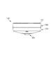
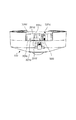
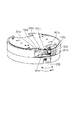
図1は、本実施形態における撮像装置としての監視カメラ100の外観図であり、図2は、本実施形態における監視カメラ100の分解斜視図である。図3は、本実施形態における監視カメラ100の下ケース301および上ケース201の分解斜視図であり、図4は、本実施形態における監視カメラ100の設置部材101および下ケース301の分解斜視図である。図5は、本実施形態における監視カメラ100の回転制限部500の詳細図である。
FIG. 1 is an external view of the
本実施形態の監視カメラ100は、図1に示すように、設置部材101と、上ケースユニット200と、下ケースユニット300と、を備えている。
As shown in FIG. 1, the
設置部材101は、固定面の一例としての天井や壁面に固定される部材であり、板金である。設置部材101は、図4に示すように、第1ロック機構の一例としてのフック101aと、くぼみ部101bと、貫通孔101cと、取付部101dと、を有している。
The
フック101aは、下ケースユニット300と係合する部分である。フック101aは、L字状であり、周方向に所定の間隔を隔てて3つ設けられている。
The
くぼみ部101bは、取付部101dから下ケースユニット300に向けて突出しており、取付部101dの端部に設けられている。
The
貫通孔101cは、後述する回転制限部材500が挿通される部分であり、くぼみ部101bに形成されている。
The through
取付部101dは、天井や壁面に固定される部分であり、円形の一部が切り欠かれた形状となっている。
The
上ケースユニット200は、図2に示すように、第2ケースの一例としての上ケース201と、ビス202と、圧縮コイルスプリング203と、を有している。
As shown in FIG. 2, the
上ケース201は、図3に示すように、円状の開口201aと、ビス孔201bと、第2ロック機構の一例としての第1リブ201cと、突出部201dと、第2リブ201eと、を有している。
As shown in FIG. 3, the
開口201aは、上ケース201の中央部に設けられており、鏡筒ユニット400が配置される。ビス孔201bには、下ケース301に固定するためのビス202が挿通される。第1リブ201cは、円周方向に間隔を隔てて3つ設けられており、それぞれに周方向に延びる溝201fが形成されている。突出部201dは、図7に示すように、溝201fの内部に向けて突出している。第2リブ201eは、上ケースユニット200を回転させたときに、後述する回転制限部500と当接する部材であり、上ケース201の内周面から内側に向けて突出している。
The opening 201a is provided in the central portion of the
ビス202は、上ケース201のビス孔201bに挿通して下ケース301と一体となるよう組み付けられる。
The
圧縮コイルスプリング203は、ビス202と上ケース201の間に狭持されて組み付けられ、ビス202を上ケース201に向けて付勢する。
The
下ケースユニット300は、図2に示すように、第1ケースの一例としての下ケース301と、第1カバー部材303と、第2カバー部材304と、図4に示す回転制限部500と、を有する。
As shown in FIG. 2, the
下ケース301は、受部301aと、スライド溝301bと、略台形状の台形部301cと、第1ロック機構の一例としての係止部301dと、第2ロック機構の一例としての第1突起301eと、ビス孔301fと、を有している。
The
受部301aは、略円筒状であり、後述する回転制限部500が配置される。
The
スライド溝301bには、後述する回転制限部500のリブ501bが配置され、回転制限部500のリブ501bをガイドする。
The
台形部301cは、円周方向において一定の間隔を隔てて、3か所設けられている。台形部301cは、高さ方向において貫通している。
The
係止部301dは、設置部材101のフック101aと係合する。係止部301dは、矩形状であり、台形部301c内に位置している。
The
第1突起301eは、下ケース301の端部から内側に向けて突出しており、上ケース201の溝201fの内部に配置される。
The
ビス孔301fは、下ケース301の第1突起301eと上ケース201の突出部201dが当接する位置において、ビス孔201bと一致する。
The
第1カバー部材303は、図2に示すように、メイン基板302を覆うように配置され、下ケース301に固定される。また、第1カバー部材303の中央部には、撮像ユニットの一例としての鏡筒ユニット400が固定される。鏡筒ユニット400は、レンズ群を有する鏡筒部と、撮像素子を有する撮像素子基板と、から構成され、鏡筒部と撮像素子基板は、図示しないFPC等の電気的接続手段によって、メイン基板302と電気的に接続される。
As shown in FIG. 2, the
第2カバー部材304は、図2に示すように、メイン基板302と、第1カバー部材303と、鏡筒ユニット400と、を覆うように配置され、下ケースに301に固定される。
As shown in FIG. 2, the
回転制限部500は、図5に示すように、監視カメラ100の高さ方向に駆動可能なスライド部材501と、付勢解除部材502と、付勢部材503と、蓋504と、を有する。
As shown in FIG. 5, the
スライド部材501は、監視カメラ100の高さ方向に沿って移動可能であり、傾斜面501aと、スライド溝301bに配置されるリブ501bと、第2突起501cと、を有している。
The
付勢解除部材502は、スライド部材501の傾斜面501aと当接する傾斜面502aと、第2リブ201eの当接する当接部502bと、を有している。
The urging
付勢部材503は、第2突起501cを設置部材101の貫通孔101cに向けて付勢している。
The urging
回転制限部500は、下ケース301に組み付けられる。下ケース301の受部301aに、付勢部材503、スライド部材501、付勢解除部材502、蓋504の順に組付けられ、蓋504は下ケース301に固定される。このとき、スライド部材501のリブ501bが下ケース301のスライド溝301bに嵌め合わされて組付けられることで、スライド部材501は、下ケース301の高さ方向に摺動可能に組付けられる。
The
また、スライド部材501の傾斜面501aと付勢解除部材502の傾斜面502aは当接するように組付けられる。これにより、付勢解除部材502を中心軸周りに回動させることで、付勢部材503の付勢を解除し、第2突起501cを下ケース301の高さ方向に動作させることが可能となる。
Further, the inclined surface 501a of the
次に、図6、図7を用いて、上ケースユニット200と下ケースユニット300との組付けについて説明する。図6および図7は、本実施形態における監視カメラの上ケースユニット200と下ケースユニット300の取付けを示す図である。なお、図6は、第2ケース301が第2解除位置に位置する状態であり、図7は、第2ケース301が第2ロック位置に位置する状態である。
Next, the assembly of the
上ケースユニット200と下ケースユニット300の組付けは、図6に示すように、まず、上ケース201の第1リブ201cと下ケース301の第1突起301eとが干渉しないように、第1リブ201cを台形部301cに挿入する。そして、上ケース201の端面と下ケース301の端面を当接させる。そして、当接状態のまま、上ケース201を下ケース301の第1突起301eに位置する第1方向に回転させ、図7に示すように、第1突起301eが上ケース201の第1リブ201cの溝201fに挿通するように係合させる。これにより、上ケースユニット200は、下ケースユニット300に対して、高さ方向の動きが制限される。また、図7に示すように、下ケース301の第1突起301eと上ケース201の突出部201dが当接する位置において、上ケースユニット200のビス孔201bと下ケースユニット300のビス孔301fの位置が一致する。この状態で、ビス202を締結することにより、上ケースユニット200と下ケースユニット300の相対回転を制限することが可能となる。なお、上ケース201を下ケース301に対して回転させる例を説明したが、下ケース301を上ケース201に対して回動させて上ケースユニット200と下ケースユニット300の組付けてもよい。
As shown in FIG. 6, the
次に、図8、図9を用いて、本実施形態における監視カメラ100の天井や壁面への設置作業について説明する。図8は、本実施形態における監視カメラ100の設置前の状態を示す図である。図9は、本実施形態における監視カメラ100の設置後の状態を示す図である。なお、図8は、第1ケース301が第1解除位置に位置し、第2ケース201が第2ロック位置に位置する状態であり、図9は、第1ケース301が第1ロック位置に位置し、第2ケース201が第2ロック位置に位置する状態である。
Next, the installation work of the
監視カメラ100の設置は、まず設置部材101を天井もしくは壁面に固定する。次に、図8に示すように、設置部材101のフック101aが、下ケースユニット300の台形部301c内に配置されるように、下ケースユニット300を設置部材101に対して配置する。そして、下ケースユニット300を第1方向(図中A方向)へ回転させ、図9に示すように、フック101aと係止部301dを係合させる。
To install the
言い換えると、第2ケース201が第2ロック位置に位置する状態で、固定面に設置された設置部材101に対して、第1ケース301を第1解除位置から第1ロック位置に向かう第1方向(A方向)に回動させることにより、監視カメラ100を固定面に設置する。 また、下ケースユニット300のA方向への回転により、回転制限部500の第2突起501cは、設置部材101のくぼみ部101bに到達すると、くぼみ部101bにより押圧された状態となる。そして、さらに回転させると、下ケースユニット300の回転制限部500が、設置部材101のくぼみ部101bに沿って移動する。そして、設置部材101の貫通孔101cに回転制限部500の第2突起501cが嵌まる位置にくると、第2突起501cは、付勢部材503の付勢力によって貫通孔101c内に配置される。これにより、下ケースユニット300の高さ方向及び回転方向の移動が制限され、図9に示す状態となり、監視カメラ100の天井もしくは壁面への設置が完了する。
In other words, with the
以上のように、本実施形態における監視カメラ100は、回転操作によって天井もしくは壁面への設置できるので、設置作業者に与える負荷が小さく、監視カメラ100の天井等への設置が容易である。
As described above, since the
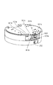
次に、図9、図10を用いて、上ケースユニット200と下ケースユニット300を一体的に設置部材101から取り外す作業について説明する。図10は、本実施形態における監視カメラ100の上ケースユニット200と下ケースユニット300を一体的に取り外す途中の状態を示す図である。図10は、第1ケース301が第1ロック位置に位置し、第2ケース201が第2ロック位置に位置する状態である。
Next, the work of integrally removing the
まず、上ケースユニット200のビス202の締結を解除することで、上ケースユニット200の回転制限を解除する。この状態で、上ケースユニット200を第2方向(図中B方向)へ回転させる。このとき、上ケースユニット200の突起201dと下ケースユニット300の第1突起301eは干渉するため、上ケースユニット200のリブ201cが第1突起301eとの干渉量分変形する。また、上ケース201に形成された第2のリブ201eによって、回転制限部500の付勢解除部材502が操作される。
First, the rotation restriction of the
これにより、第2突起501cが設置部材101から離れる方向に移動し、設置部材101と下ケースユニット300の回転制限が解除される。さらに、同方向に回転させることで、図10に示す状態となる。そして、さらに回転させ、フック101aと係止部301dとの係合が解除されると、上ケースユニット200と下ケースユニット300を一体的に設置部材101から取り外すことが可能となる。
As a result, the
言い換えると、第1ケース301が第1ロック位置にあり、第2ケース201が第2ロック位置にある状態から第2ケース201を第1方向と反対方向である第2方向(B方向)に回動させることにより、第1ケース301が第1ロック位置から第1解除位置に回動し、第1ケース301と第2ケース201を一体的に設置部材101から取り外し可能である。
In other words, from the state where the
以上のように、本実施形態における監視カメラ100は、容易な構成で、上ケース201および下ケース301を一体的に設置部材101から取り外すことができる。
As described above, the
次に、図9、図11を用いて、上ケースユニット200を下ケースユニット300から取り外す作業について説明する。図11は、本実施形態における監視カメラ100の上ケースユニット200を取り外す状態を示す図である。図11は、第1ケース301が第1ロック位置に位置し、第2ケース201が第2解除位置に位置する状態である。
Next, the work of removing the
まず、上ケースユニット200のビス202の締結を解除することで、上ケースユニット200の回転制限を解除する。この状態で、上ケースユニット200を第1方向(図中C方向)へ回転させる。これにより、図11に示すように、上ケースユニット200の第1リブ201cと下ケースユニット300第1突起301eの係合状態が解除され、監視カメラ100から上ケースユニット200のみを取り外すことが可能となる。このとき、下ケースユニット300と設置部材101の係合状態および回転制限状態は維持されている。
First, the rotation restriction of the
言い換えると、第1ケース301を第1ロック位置に配置させた状態で第2ケース201を第2ロック位置から第2解除位置に向かう第1方向(C方向)に回動させることにより、第1ケース301が設置部材101に固定された状態で第2ケース201を第1ケース301から取り外し可能である、
以上のように、本実施形態における監視カメラ100は、容易な構成で、上ケースユニット200のみを取り外すことができるため、下ケースユニット300を設置状態のまま、鏡筒ユニット400のメンテナンスを実施することができる。
In other words, by rotating the
As described above, since the
また、上ケースユニット200の突出部201dと下ケースユニット300の第1突起301eとが当接しない方向回転させるため、上ケースユニット200および下ケースユニット300を一体的に取り外す場合と比較すると、回転操作のために必要とする操作トルクは小さい。
Further, since the protruding
これにより、作業者に取り外すユニットを認識させて、例えば、下ケースユニット300を設置状態のまま、メンテナンスを実施したい場合に、下ケースユニット300と上ケースユニット200を一体的に取り外してしまうことを抑制することが可能になる。
As a result, the operator is made to recognize the unit to be removed, and for example, when the
また、下ケースユニット300と上ケースユニット200を一体的に取り外す場合に上ケースユニット200を回転させる方向(B方向)と、上ケースユニット200のみを取り外す場合に上ケースユニット200を回転させる方向(C方向)とが、逆方向である。
Further, a direction in which the
これにより、作業者が、誤操作をすることを抑制することができる。 As a result, it is possible to prevent the operator from making an erroneous operation.
以上、本発明をその好適な実施形態に基づいて詳述してきたが、本発明はこれら特定の実施形態に限られるものではなく、この発明の要旨を逸脱しない範囲の様々な形態も本発明に含まれる。また、上述した実施形態の一部を適宜組み合わせても良い。 Although the present invention has been described in detail based on the preferred embodiments thereof, the present invention is not limited to these specific embodiments, and various embodiments within the scope of the gist of the present invention are also included in the present invention. included. In addition, some of the above-described embodiments may be combined as appropriate.
100 監視カメラ
101 設置部材
101a フック
101c 貫通孔
200 上ケースユニット
201 上ケース
201c 第1リブ
201d 突出部
201e 第2リブ
201f 溝
300 下ケースユニット
301 下ケース
301d 係止部
301e 第1突起
502 付勢解除部材
502c 第2突起
503 付勢部材
100
Claims (7)
内部に撮像ユニットが配置され、前記設置部材に対して着脱可能に構成される第1ケースと、
前記第1ケースの内部に配置された前記撮像ユニットを覆うように構成されるとともに、前記第1ケースに対して着脱可能に構成される第2ケースと、を備え、
前記第2ケースは、第1方向に回転させることにより、前記設置部材に装着された前記第1ケースから取り外し可能であり、前記第1方向と反対方向である第2方向に回転させることにより、前記第1ケースと一体的に前記設置部材から取り外し可能である、撮像装置。 Installation members fixed to the fixed surface and
A first case in which an imaging unit is arranged and is removable from the installation member ,
A second case configured to cover the imaging unit arranged inside the first case and detachable from the first case is provided.
The second case can be removed from the first case mounted on the installation member by rotating in the first direction, and by rotating in the second direction opposite to the first direction. An imaging device that can be removed from the installation member integrally with the first case .
前記第1ケースが第1ロック位置にあり、前記第2ケースが第2ロック位置にある状態から前記第2ケースを前記第1方向と反対方向である第2方向に回動させることにより、前記第1ケースが前記第1ロック位置から前記第1解除位置に回動し、前記第1ケースと前記第2ケースを一体的に前記設置部材から取り外し可能である、請求項1に記載の撮像装置。 The first case can rotate between the first lock position and the first release position, and the second case can rotate between the second lock position and the second release position.
By rotating the second case in the second direction opposite to the first direction from the state where the first case is in the first lock position and the second case is in the second lock position, the said The imaging device according to claim 1, wherein the first case rotates from the first lock position to the first release position, and the first case and the second case can be integrally removed from the installation member. ..
前記第2ケースに設けられ、溝を有する第1リブと、前記第1ケースに設けられ、前記第1リブの前記溝に配置される第1突起とからなる第2ロック機構と、を備え、A second locking mechanism including a first rib provided in the second case and having a groove and a first protrusion provided in the first case and arranged in the groove of the first rib is provided.
前記第1ロック位置は、前記係止部が前記フックによって係止されることにより前記設置部材に対して前記第1ケースが固定される位置であり、The first lock position is a position where the first case is fixed to the installation member by locking the locking portion with the hook.
前記第1解除位置は、前記係止部の前記係止が解除されることにより前記設置部材から前記第1ケースが取り外し可能な位置であり、The first release position is a position where the first case can be removed from the installation member by releasing the lock of the locking portion.
前記第2ロック位置は、前記溝に前記第1突起が配置されることにより前記第1ケースに対して前記第2ケースが固定される位置であり、The second lock position is a position where the second case is fixed to the first case by arranging the first protrusion in the groove.
前記第2解除位置は、前記溝の外に前記第1突起が配置されることにより前記第1ケースから前記第2ケースが取り外し可能な位置である、請求項2または3に記載の撮像装置。The imaging device according to claim 2 or 3, wherein the second release position is a position where the second case can be removed from the first case by arranging the first protrusion outside the groove.
前記突出部は、
前記第1ケースと前記第2ケースを一体的に前記設置部材から取り外す場合、前記第1突起と当接し、
前記第1ケースが前記設置部材に固定された状態で前記第2ケースを前記第1ケースから取り外す場合、前記第1突起と当接しない、請求項4に記載の撮像装置。 The groove has a protrusion that projects toward the inside of the groove.
The protrusion
When the first case and the second case are integrally removed from the installation member, they come into contact with the first protrusion.
The imaging device according to claim 4 , wherein when the second case is removed from the first case while the first case is fixed to the installation member, the first case does not come into contact with the first protrusion.
前記第1ケースは、前記貫通孔に前記第2突起が挿通されることにより、前記第1ロック位置から前記第1解除位置への回動を制限される、請求項4または5に記載の撮像装置。 The installation member has a through hole, and the first case has a second protrusion inserted through the through hole.
The imaging image according to claim 4 or 5 , wherein in the first case, rotation from the first lock position to the first release position is restricted by inserting the second protrusion into the through hole. apparatus.
前記付勢解除部材が、前記第2ケースが回動した際に前記第2ケースと当接することで前記付勢部材の前記第2突起への付勢が解除され、前記第2突起は前記貫通孔の外に位置する、請求項6に記載の撮像装置。 The first case includes an urging member that urges the second protrusion toward the through hole to allow the second protrusion to pass through the through hole, and an attachment that releases the urging to the second protrusion. Has a force release member,
When the second case rotates, the urging release member comes into contact with the second case, so that the urging member is released from urging the second projection, and the second projection penetrates the second projection. The imaging apparatus according to claim 6 , which is located outside the hole.
Priority Applications (3)
| Application Number | Priority Date | Filing Date | Title |
|---|---|---|---|
| JP2017066282A JP6797733B2 (en) | 2017-03-29 | 2017-03-29 | Imaging device |
| US15/927,884 US10477081B2 (en) | 2017-03-29 | 2018-03-21 | Imaging apparatus for use on a ceiling or wall surface |
| CN201810255953.0A CN108692160B (en) | 2017-03-29 | 2018-03-27 | Imaging device for use on ceiling or wall |
Applications Claiming Priority (1)
| Application Number | Priority Date | Filing Date | Title |
|---|---|---|---|
| JP2017066282A JP6797733B2 (en) | 2017-03-29 | 2017-03-29 | Imaging device |
Publications (3)
| Publication Number | Publication Date |
|---|---|
| JP2018169486A JP2018169486A (en) | 2018-11-01 |
| JP2018169486A5 JP2018169486A5 (en) | 2020-04-09 |
| JP6797733B2 true JP6797733B2 (en) | 2020-12-09 |
Family
ID=63670183
Family Applications (1)
| Application Number | Title | Priority Date | Filing Date |
|---|---|---|---|
| JP2017066282A Active JP6797733B2 (en) | 2017-03-29 | 2017-03-29 | Imaging device |
Country Status (3)
| Country | Link |
|---|---|
| US (1) | US10477081B2 (en) |
| JP (1) | JP6797733B2 (en) |
| CN (1) | CN108692160B (en) |
Families Citing this family (1)
| Publication number | Priority date | Publication date | Assignee | Title |
|---|---|---|---|---|
| CN111294555B (en) * | 2020-01-17 | 2020-09-29 | 广东铭信工程项目管理有限公司 | Project supervision and supervision system |
Family Cites Families (13)
| Publication number | Priority date | Publication date | Assignee | Title |
|---|---|---|---|---|
| KR960014143B1 (en) | 1994-08-16 | 1996-10-14 | 삼성전자 주식회사 | Monitor stand |
| US6268882B1 (en) * | 1998-12-31 | 2001-07-31 | Elbex Video Ltd. | Dome shaped camera with simplified construction and positioning |
| KR100362609B1 (en) * | 2000-11-30 | 2002-11-29 | 삼성전자 주식회사 | Dome camera apparatus |
| JP2003189138A (en) | 2001-12-20 | 2003-07-04 | Fujitsu General Ltd | Crime prevention camera |
| JP4356551B2 (en) * | 2004-08-06 | 2009-11-04 | パナソニック電工株式会社 | Imaging device |
| US7217045B2 (en) * | 2005-01-03 | 2007-05-15 | Robert Bosch Gmbh | Connect/disconnect mechanism for a surveillance camera head |
| US7387453B2 (en) | 2005-09-02 | 2008-06-17 | Pelco, Inc. | Camera support and mounting assembly |
| JP4640267B2 (en) * | 2006-06-13 | 2011-03-02 | パナソニック株式会社 | Wiring equipment and surveillance camera device |
| CN201345691Y (en) | 2009-01-14 | 2009-11-11 | 远业科技股份有限公司 | Improved monitor structure |
| US9460595B2 (en) * | 2011-08-30 | 2016-10-04 | Kaipo Chen | Multiple detection function modularized lighting device |
| US9386226B2 (en) | 2012-11-16 | 2016-07-05 | Panasonic Intellectual Property Corporation Of America | Camera drive device |
| CN203522874U (en) | 2013-09-05 | 2014-04-02 | 动力盈科实业(深圳)有限公司 | Sliding type semi-spherical camera |
| CN203968222U (en) * | 2014-07-09 | 2014-11-26 | 杭州海康威视数字技术股份有限公司 | A kind of video camera with quick installation mechanism |
-
2017
- 2017-03-29 JP JP2017066282A patent/JP6797733B2/en active Active
-
2018
- 2018-03-21 US US15/927,884 patent/US10477081B2/en active Active
- 2018-03-27 CN CN201810255953.0A patent/CN108692160B/en active Active
Also Published As
| Publication number | Publication date |
|---|---|
| US20180288290A1 (en) | 2018-10-04 |
| CN108692160B (en) | 2020-04-10 |
| US10477081B2 (en) | 2019-11-12 |
| CN108692160A (en) | 2018-10-23 |
| JP2018169486A (en) | 2018-11-01 |
Similar Documents
| Publication | Publication Date | Title |
|---|---|---|
| JP6064458B2 (en) | Imaging device | |
| JP5412913B2 (en) | Imaging device mounting mechanism and imaging device | |
| US7623773B2 (en) | Accessory device for image-pickup apparatus | |
| JPWO2017038272A1 (en) | Imaging device, camera grip, and imaging system | |
| US20150212395A1 (en) | Imaging apparatus and imaging system | |
| JP6797733B2 (en) | Imaging device | |
| US5384614A (en) | Lens installing/removing device | |
| JP4798178B2 (en) | Lens barrel and imaging device | |
| JP2017517022A (en) | Telescopic position limiting structure, camera body and camera | |
| US6377408B1 (en) | Lens barrel | |
| JP2008180914A (en) | Stroboscopic device | |
| JP2019033406A (en) | Imaging apparatus | |
| JP6448349B2 (en) | Projection-type image display device | |
| JP2001188285A (en) | Cam device | |
| JP6330898B2 (en) | Imaging device | |
| US8941922B2 (en) | Lens apparatus and image pickup apparatus including the lens apparatus | |
| JP6597832B2 (en) | Imaging device | |
| JP2010054660A (en) | Camera | |
| JP2020085922A (en) | Monitor camera, ad monitor camera cover attachment method | |
| JP2015190748A (en) | ventilation unit | |
| JP2018169486A5 (en) | ||
| JP5590949B2 (en) | Front accessory attachment / detachment mechanism for photographic lenses | |
| JP4707554B2 (en) | Camera device | |
| JP2008033220A (en) | Imaging apparatus | |
| JP2022160913A (en) | Communication apparatus installation structure |
Legal Events
| Date | Code | Title | Description |
|---|---|---|---|
| A521 | Request for written amendment filed |
Free format text: JAPANESE INTERMEDIATE CODE: A523 Effective date: 20200227 |
|
| A621 | Written request for application examination |
Free format text: JAPANESE INTERMEDIATE CODE: A621 Effective date: 20200227 |
|
| TRDD | Decision of grant or rejection written | ||
| A977 | Report on retrieval |
Free format text: JAPANESE INTERMEDIATE CODE: A971007 Effective date: 20201014 |
|
| A01 | Written decision to grant a patent or to grant a registration (utility model) |
Free format text: JAPANESE INTERMEDIATE CODE: A01 Effective date: 20201020 |
|
| A61 | First payment of annual fees (during grant procedure) |
Free format text: JAPANESE INTERMEDIATE CODE: A61 Effective date: 20201118 |
|
| R151 | Written notification of patent or utility model registration |
Ref document number: 6797733 Country of ref document: JP Free format text: JAPANESE INTERMEDIATE CODE: R151 |