JP6796640B2 - Workpiece Machining Systems and Methods with Setup Modules - Google Patents
Workpiece Machining Systems and Methods with Setup Modules Download PDFInfo
- Publication number
- JP6796640B2 JP6796640B2 JP2018516650A JP2018516650A JP6796640B2 JP 6796640 B2 JP6796640 B2 JP 6796640B2 JP 2018516650 A JP2018516650 A JP 2018516650A JP 2018516650 A JP2018516650 A JP 2018516650A JP 6796640 B2 JP6796640 B2 JP 6796640B2
- Authority
- JP
- Japan
- Prior art keywords
- module
- machining
- tool holder
- workpiece
- workpiece carrier
- Prior art date
- Legal status (The legal status is an assumption and is not a legal conclusion. Google has not performed a legal analysis and makes no representation as to the accuracy of the status listed.)
- Active
Links
- 238000003754 machining Methods 0.000 title claims description 126
- 238000000034 method Methods 0.000 title claims description 7
- 238000004519 manufacturing process Methods 0.000 claims description 23
- 238000012937 correction Methods 0.000 claims description 11
- 238000012546 transfer Methods 0.000 claims description 6
- 238000005286 illumination Methods 0.000 description 8
- 238000005259 measurement Methods 0.000 description 8
- 239000000463 material Substances 0.000 description 7
- 230000003287 optical effect Effects 0.000 description 7
- 238000012360 testing method Methods 0.000 description 7
- 239000000969 carrier Substances 0.000 description 4
- 238000000605 extraction Methods 0.000 description 4
- 239000003517 fume Substances 0.000 description 4
- 230000001681 protective effect Effects 0.000 description 4
- 230000007547 defect Effects 0.000 description 3
- 238000010586 diagram Methods 0.000 description 3
- 238000004590 computer program Methods 0.000 description 2
- 230000001939 inductive effect Effects 0.000 description 2
- 238000003780 insertion Methods 0.000 description 2
- 230000037431 insertion Effects 0.000 description 2
- 238000009434 installation Methods 0.000 description 2
- 239000007788 liquid Substances 0.000 description 2
- 238000011084 recovery Methods 0.000 description 2
- 238000012795 verification Methods 0.000 description 2
- 238000010923 batch production Methods 0.000 description 1
- 210000001520 comb Anatomy 0.000 description 1
- 239000002173 cutting fluid Substances 0.000 description 1
- 238000005520 cutting process Methods 0.000 description 1
- 239000011521 glass Substances 0.000 description 1
- 238000010191 image analysis Methods 0.000 description 1
- 238000007689 inspection Methods 0.000 description 1
- 230000001050 lubricating effect Effects 0.000 description 1
- 238000012423 maintenance Methods 0.000 description 1
- 239000011159 matrix material Substances 0.000 description 1
- 238000003801 milling Methods 0.000 description 1
- 238000000206 photolithography Methods 0.000 description 1
- 238000012545 processing Methods 0.000 description 1
- 239000002994 raw material Substances 0.000 description 1
- 238000004088 simulation Methods 0.000 description 1
- 238000005507 spraying Methods 0.000 description 1
- 239000000758 substrate Substances 0.000 description 1
- 230000000007 visual effect Effects 0.000 description 1
Images


Classifications
-
- B—PERFORMING OPERATIONS; TRANSPORTING
- B23—MACHINE TOOLS; METAL-WORKING NOT OTHERWISE PROVIDED FOR
- B23Q—DETAILS, COMPONENTS, OR ACCESSORIES FOR MACHINE TOOLS, e.g. ARRANGEMENTS FOR COPYING OR CONTROLLING; MACHINE TOOLS IN GENERAL CHARACTERISED BY THE CONSTRUCTION OF PARTICULAR DETAILS OR COMPONENTS; COMBINATIONS OR ASSOCIATIONS OF METAL-WORKING MACHINES, NOT DIRECTED TO A PARTICULAR RESULT
- B23Q17/00—Arrangements for observing, indicating or measuring on machine tools
- B23Q17/22—Arrangements for observing, indicating or measuring on machine tools for indicating or measuring existing or desired position of tool or work
- B23Q17/2233—Arrangements for observing, indicating or measuring on machine tools for indicating or measuring existing or desired position of tool or work for adjusting the tool relative to the workpiece
- B23Q17/2266—Arrangements for observing, indicating or measuring on machine tools for indicating or measuring existing or desired position of tool or work for adjusting the tool relative to the workpiece of a tool relative to a workpiece-axis
-
- B—PERFORMING OPERATIONS; TRANSPORTING
- B23—MACHINE TOOLS; METAL-WORKING NOT OTHERWISE PROVIDED FOR
- B23Q—DETAILS, COMPONENTS, OR ACCESSORIES FOR MACHINE TOOLS, e.g. ARRANGEMENTS FOR COPYING OR CONTROLLING; MACHINE TOOLS IN GENERAL CHARACTERISED BY THE CONSTRUCTION OF PARTICULAR DETAILS OR COMPONENTS; COMBINATIONS OR ASSOCIATIONS OF METAL-WORKING MACHINES, NOT DIRECTED TO A PARTICULAR RESULT
- B23Q1/00—Members which are comprised in the general build-up of a form of machine, particularly relatively large fixed members
- B23Q1/01—Frames, beds, pillars or like members; Arrangement of ways
- B23Q1/015—Frames, beds, pillars
-
- B—PERFORMING OPERATIONS; TRANSPORTING
- B23—MACHINE TOOLS; METAL-WORKING NOT OTHERWISE PROVIDED FOR
- B23Q—DETAILS, COMPONENTS, OR ACCESSORIES FOR MACHINE TOOLS, e.g. ARRANGEMENTS FOR COPYING OR CONTROLLING; MACHINE TOOLS IN GENERAL CHARACTERISED BY THE CONSTRUCTION OF PARTICULAR DETAILS OR COMPONENTS; COMBINATIONS OR ASSOCIATIONS OF METAL-WORKING MACHINES, NOT DIRECTED TO A PARTICULAR RESULT
- B23Q17/00—Arrangements for observing, indicating or measuring on machine tools
- B23Q17/22—Arrangements for observing, indicating or measuring on machine tools for indicating or measuring existing or desired position of tool or work
- B23Q17/2233—Arrangements for observing, indicating or measuring on machine tools for indicating or measuring existing or desired position of tool or work for adjusting the tool relative to the workpiece
-
- B—PERFORMING OPERATIONS; TRANSPORTING
- B23—MACHINE TOOLS; METAL-WORKING NOT OTHERWISE PROVIDED FOR
- B23Q—DETAILS, COMPONENTS, OR ACCESSORIES FOR MACHINE TOOLS, e.g. ARRANGEMENTS FOR COPYING OR CONTROLLING; MACHINE TOOLS IN GENERAL CHARACTERISED BY THE CONSTRUCTION OF PARTICULAR DETAILS OR COMPONENTS; COMBINATIONS OR ASSOCIATIONS OF METAL-WORKING MACHINES, NOT DIRECTED TO A PARTICULAR RESULT
- B23Q17/00—Arrangements for observing, indicating or measuring on machine tools
- B23Q17/24—Arrangements for observing, indicating or measuring on machine tools using optics or electromagnetic waves
Description
本発明は、セット・アップ・モジュールと、生産するように意図された少なくとも1つの機械加工モジュールとを含む方法及びワークピース機械加工システムに関する。 The present invention relates to methods and workpiece machining systems that include set-up modules and at least one machining module intended to be produced.
機械加工モジュール(マシン・ツール)、とりわけ、バー・ターニング・マシン、自動旋盤、ミーリング・マシン、及び移送機械を使用して、ワークピースを製造することは、典型的に、3つの別々の局面を含む。 Manufacture of workpieces using machining modules (machine tools), in particular bar turning machines, automatic lathes, milling machines, and transfer machines, typically involves three separate aspects. Including.
第1のセット・アップ(又は、プリセット)局面では、オペレータ(たとえば、バー・ターナー・オペレータ)は、機械加工モジュールの上で、機械加工平面を定義してテストし、すなわち、機械加工されることとなる所望のワークピースを得るために必要とされる動作のシーケンス及び軸移動を定義してテストする。たとえば、オペレータは、最も効率的な機械加工平面が可能な限り得られることを確実にし、すなわち、ツール間の衝突、又は、ワークピースとの衝突を回避しながら、所与のワークピースが最小の動作によって機械加工されることを可能にすることを確実にする。オペレータは、使用されることとなるツールを選び、また、得られるワークピースの品質、たとえば、表面条件、公差の順守などをチェックする。 In the first set-up (or preset) phase, the operator (eg, the bar turner operator) defines and tests the machining plane on the machining module, i.e. machined. Define and test the sequence of movements and axial movements required to obtain the desired workpiece. For example, the operator ensures that the most efficient machining plane is obtained as much as possible, i.e., while avoiding collisions between tools or collisions with workpieces, given workpieces are minimal. Ensure that the motion allows it to be machined. The operator selects the tool to be used and also checks the quality of the resulting workpiece, such as surface conditions, tolerance compliance, etc.
第2の生産局面では、ワークピースのバッチは、プリセットされた機械加工モジュールの上で作り出され、パラメータは、セット・アップ局面の間に定義される。これは、生産的な局面だけである。多くの場合、それは、1日に24時間実施され、原材料は、バー・フィーダ又はスラグ(ブランク)・ローダによって、機械加工モジュールに給送される。 In the second production phase, batches of workpieces are created on top of preset machining modules and parameters are defined during the set-up phase. This is only the productive aspect. Often it is carried out 24 hours a day and the raw materials are fed to the machining module by a bar feeder or slug (blank) loader.
ワークピースのバッチの生産は、たとえば、同じ機械加工モジュールの上で別のタイプのワークピースを作り出すために中断され得、マシンのメンテナンスなどを可能にし、次いで、その後に再開される。このケースでは、始動局面が、セット・アップ局面の間に以前に定義されたパラメータを適用するために必要である。この始動局面は、セット・アップ局面よりも速い。 Batch production of workpieces can be interrupted, for example, to produce different types of workpieces on the same machining module, allowing maintenance of the machine, etc., and then resumed. In this case, the starting phase is required to apply the previously defined parameters during the set-up phase. This starting phase is faster than the set-up phase.
セット・アップの間にテストされた結果が得られることを可能にするプリセットされたパラメータによって、この生産が行われるということを確実にするために、セット・アップは、一般的に、生産のためにも使用され得る機械加工モジュールの上で実施される。これにより、生産が中断され(すなわち、アイドル時間)、また、生産機械がセット・アップ期間の期間中に動けなくなる。 Set-ups are generally for production to ensure that this production is done with preset parameters that allow the results tested during the set-up to be obtained. It is carried out on a machining module that can also be used. This interrupts production (ie, idle time) and also prevents the production machine from moving during the set-up period.
セット・アップ局面の間にプリセットされた機械加工パラメータをテストするために、たとえば、センサ、ビデオ・カメラなどの、特殊化した検査機器が、作り出されるワークピースの品質を測定するために必要とされる。このテスト機器は、機械加工モジュールの価格をより高価にする。多くの機械加工モジュールを備える設備のケースでは、それぞれのモジュールは、少なくともそれぞれのセット・アップ局面に関して、それ自身のテスト機器を装備している必要がある。ワークピースを外部でテストするために、機械加工モジュールからワークピースを除去することが可能であるが、この移送は、セット・アップ局面及びモジュールの非生産的な動かない時間をさらに遅くする。そのうえ、それは、機械加工プロセスの中間ステップの間のワークピースの特性の容易な測定を可能にしない。 Specialized inspection equipment, such as sensors and video cameras, is needed to measure the quality of the workpieces produced to test the preset machining parameters during the set-up phase. To. This test equipment makes the price of the machining module more expensive. In the case of equipment with many machining modules, each module must be equipped with its own test equipment, at least for each set-up phase. Although it is possible to remove the workpiece from the machining module for external testing of the workpiece, this transfer further slows down the set-up phase and the unproductive immobility time of the module. Moreover, it does not allow easy measurement of the properties of the workpiece during the intermediate steps of the machining process.
したがって、このセット・アップ局面又は始動局面の期間を低減させるために、さまざまな解決策が、先行技術において提案されてきた。 Therefore, various solutions have been proposed in the prior art to reduce the duration of this set-up or start-up phase.
たとえば、特許文献1は、外部セット・アップ・デバイスを説明している。このデバイスは、セット・アップがマシン・ツールの外側で実施されることを可能にし、また、得られたパラメータが生産機械の上で生産局面の前にテストされることを可能にする。セット・アップは、取り外し可能なツール・ホルダの上に装着されているツールを使用して実施され、取り外し可能なツール・ホルダは、次いで、生産機械へ移送され、ツールの変化、又は、それらのツール・ホルダの中でのツールの位置決めの変化によって、生産品質が影響を受けないことを確実にするようになっている。 For example, Patent Document 1 describes an external set-up device. This device allows the set-up to be performed outside the machine tool and also allows the obtained parameters to be tested on the production machine before the production phase. Set-up is performed using tools mounted on top of removable tool holders, which are then transferred to the production machine to change tools, or theirs. Changes in tool positioning within the tool holder ensure that production quality is unaffected.
特許文献2は、数値制御を備えたマシン・ツールを説明している。数値的位置決めデバイスは、取り外し可能なツール・ホルダの位置決めを補正することを助け、また、必要とされる位置決めパラメータを穿孔テープの上に記録することを助ける。この解決策は、上記の文献と同じ欠点を有しており、ツール位置決めの差が補正されることを可能にするだけである。 Patent Document 2 describes a machine tool provided with numerical control. The numerical positioning device helps to correct the positioning of the removable tool holder and also helps to record the required positioning parameters on the perforated tape. This solution has the same drawbacks as the above literature and only allows the difference in tool positioning to be corrected.
特許文献3は、別の数値的回路を説明しており、それは、セット・アップの間に事前決定されたツールの位置が生産の間に再現されることを可能にし、したがって、始動時間を低減させる。 Patent Document 3 describes another numerical circuit, which allows the position of the tool predetermined during set-up to be reproduced during production and thus reduces start-up time. Let me.
特許文献4は、ツールをそれらのツール・ホルダの中にプリセットするための方法を説明している。その方法は、取り外し可能なツール・ホルダを備えた外部セット・アップ・デバイスを実装しており、取り外し可能なツール・ホルダは、次いで、生産マシン・ツールに移送され得る。マシン・ツールは、ツール・ホルダの相対的位置決めを正しく再現する。 Patent Document 4 describes a method for presetting tools in those tool holders. The method implements an external set-up device with a removable tool holder, which can then be transferred to the production machine tool. The machine tool correctly reproduces the relative positioning of the tool holder.
特許文献5及び特許文献6は、シミュレーション・デバイスに関し、それは、マシン・ツールがプリセットされることを可能にし、外部セット・アップ・デバイスを実装している。 Patent Document 5 and Patent Document 6 relate to a simulation device, which allows machine tools to be preset and implements an external set-up device.
特許文献7、特許文献8、特許文献9及び特許文献10は、マシン・ツールをプリセットするためのデバイスを説明しており、取り外し可能なツール・ホルダを備えた外部セット・アップ・デバイスを実装している。 Patent Document 7, Patent Document 8, Patent Document 9, and Patent Document 10 describe a device for presetting a machine tool, and implement an external set-up device having a removable tool holder. ing.
特許文献11は、いくつかのツール・ホルダを担持するコンベヤーを装備している生産テーブルを備えた生産機械を説明しており、ひいては、ツール・ホルダは、それぞれ、一連の隣接する加工ステーションの中の位置をとることができる。 Patent Document 11 describes a production machine equipped with a production table equipped with a conveyor carrying several tool holders, and thus each tool holder is in a series of adjacent processing stations. Can take the position of.
特許文献12は、マシン・ツールに関し、そのシャーシーは、ワークピース・キャリア及び1つ又は複数のツール・ホルダを支持するフレームを形成している。シャーシーの上でのワークピース・キャリア及びツール・ホルダの正しい位置決めを確実にするためのシステムが存在している。 Patent Document 12 relates to a machine tool whose chassis forms a frame that supports a workpiece carrier and one or more tool holders. Systems exist to ensure proper positioning of workpiece carriers and tool holders on the chassis.
特許文献13は、いくつかの整合された機械加工セル、及び、機械加工されることとなるワークピースを輸送するための輸送デバイスを備えたワークピース生産ラインを説明している。それぞれの機械加工セルは、ツール・ホルダ及びワークピース・キャリアを含む。ツール・ホルダとそれに関連付けられているワークピース・キャリアとの間の相対的位置補償が存在している。 Patent Document 13 describes a workpiece production line comprising several matched machined cells and a transport device for transporting the workpiece to be machined. Each machined cell contains a tool holder and a workpiece carrier. There is relative position compensation between the tool holder and the workpiece carrier associated with it.
また、特許文献14が引用され得、マシン・ツールの上のツール、パーツ、又は測定システムを調整するための光学デバイスを説明している。Also, Patent Document 14 can be cited to describe an optical device for adjusting a tool, part, or measuring system on a machine tool.
したがって、これらの異なる解決策は、生産することが意図された機械加工モジュールの外側で、機械加工平面をセット・アップ及びテストすることを可能にする。また、それらは、ツールをテストするために使用されてもよく、また、ツール・ホルダの上にツールを装着するために使用されてもよく、また、ツールをそれらのツール・ホルダの上に正確に装着することが生産の間に再現されることを確実にするために使用されてもよい。しかし、これらの解決策は、生産機械の上の結果の完全な再現性を保証しない。また、実際に、機械加工品質は、それぞれのモジュールの上のワークピース・キャリアの特性及び位置決めに依存する。 Therefore, these different solutions allow the machining plane to be set up and tested outside the machining module intended to be produced. They also may be used to test the tool, also may be used to mount the tools on the tool holder, also the tool exactly on their tool holder it may be used to be mounted to ensure that the reproduced during production. However, these solutions do not guarantee complete reproducibility of the results on the production machine. Also, in practice, the machining quality depends on the characteristics and positioning of the workpiece carrier on each module.
本発明の1つの目的は、先行技術の制限を有さない機械加工システム及び外部セット・アップ・モジュールを提案することである。 One object of the present invention is to propose a machining system and an external set-up module without prior art limitations.
本発明によれば、これらの目的は、とりわけ、ワークピースを作り出すように意図されている機械加工モジュールとセット・アップ・モジュールとを含むワークピース機械加工システムであって、
セット・アップ・モジュールは、ツール・ホルダを取り外し可能に取り付けるための少なくとも1つの第1のツール・ホルダ取り付けデバイスと、ワークピース・キャリアを取り外し可能に取り付けるための少なくとも1つの第1のワークピース・キャリア取り付けデバイスと、前記ワークピース・キャリアに対する前記少なくとも1つのツール・ホルダの位置決めを制御するための第1の位置決め制御デバイスとを含み、
機械加工モジュールは、ツール・ホルダを取り外し可能に取り付けるための少なくとも1つの第2のツール・ホルダ取り付けデバイスと、ワークピース・キャリアを取り外し可能に取り付けるための少なくとも1つの第2のワークピース・キャリア取り付けデバイスと、前記ワークピース・キャリアに対する前記少なくとも1つのツール・ホルダの位置決めをチェックするように適合された第2の位置決め制御デバイスとを含み、
ツール・ホルダ及びワークピース・キャリアが、セット・アップの後に、両方とも、セット・アップ・モジュールから機械加工モジュールへ移送され得るようになっている、ワークピース機械加工システムによって実現される。
According to the present invention, these objectives are, among other things, a workpiece machining system comprising a machining module and a set-up module intended to produce a workpiece.
The set-up module includes at least one first tool holder mounting device for detachably mounting the tool holder and at least one first workpiece for detachably mounting the workpiece carrier. Includes a carrier mounting device and a first positioning control device for controlling the positioning of the at least one tool holder with respect to the workpiece carrier .
The machining module includes at least one second tool holder mounting device for detachably mounting the tool holder and at least one second workpiece carrier mounting for detachably mounting the workpiece carrier. Includes a device and a second positioning control device adapted to check the positioning of the at least one tool holder with respect to the workpiece carrier .
Both the tool holder and the workpiece carrier are provided by a workpiece machining system that allows the tool holder and workpiece carrier to be transferred from the set-up module to the machining module after set-up.
この解決策は、セット・アップ・モジュールと機械加工モジュールとの間で、ツール・ホルダの移送だけでなく、ワークピース・キャリアの移送も可能にするという、先行技術を上回る特定の利点を有する。これは、セット・アップの間に以前にテストされたツール・ホルダ及びワークピース・キャリアによって、機械加工が実施されることを確実にする。したがって、ワークピース・キャリアの中の任意の不具合、たとえば、位置決め及び同心性などの不正確さが、セット・アップの間に測定され得、生産の間に補正又は補償され得る。 This solution has a specific advantage over prior art that it allows the transfer of workpiece carriers as well as the transfer of tool holders between set-up modules and machining modules. This ensures that machining is performed by tool holders and workpiece carriers that were previously tested during set-up. Thus, any defects in the workpiece carrier, such as inaccuracies such as positioning and concentricity, can be measured during set-up and corrected or compensated during production.
また、この解決策は、生産するように意図されている機械加工モジュールを占領することなく、外部セット・アップ・モジュールの上で、セット・アップがバックグラウンド・タスクとして実施されることを可能にする。 This solution also allows set-up to be performed as a background task on top of an external set-up module without occupying the machining module intended to be produced. To do.
好適な実施形態では、セット・アップ・モジュールは、ワークピース・キャリアに対する少なくとも1つのツール・ホルダの位置決めを制御するための第1の位置決め基準を含む。機械加工モジュールは、第2の位置決め基準を含み、第2の位置決め基準は、ワークピース・キャリアに対する少なくとも1つのツール・ホルダの位置決めをチェックするために使用され得る。これは、セット・アップ・モジュールの上でのセット・アップの間に、及び、機械加工の間に、ワークピースに対するツール・ホルダ又はそれぞれのツール・ホルダの位置決めのエラーを補償することを可能にする。 In a preferred embodiment, the set-up module includes a first positioning criterion for controlling the positioning of at least one tool holder with respect to the workpiece carrier. The machining module includes a second positioning reference, which can be used to check the positioning of at least one tool holder with respect to the workpiece carrier. This makes it possible to compensate for errors in the positioning of the tool holders or their respective tool holders with respect to the workpiece during set-up on the set-up module and during machining. To do.
ツール・ホルダは、スライド(コーム(comb))に取り外し可能に取り付けられ得る。このために、それは、たとえば、取り外し可能な取り付け手段、たとえば、1つ又は複数のピン、又は、移動可能なスライドと係合することができる部分、たとえば、基準孔部若しくは表面を含むことが可能である。 The tool holder can be detachably attached to a slide (comb). To this end, it may include, for example, removable mounting means, such as one or more pins, or a portion that can engage a movable slide, such as a reference hole or surface. Is.
ツール・ホルダは、取り外し可能に取り付けられているいくつかのツールを含むことが可能である。 The tool holder can include several tools that are detachably attached.
機械加工モジュールの上に設けられた位置決め基準は、ツール・ホルダ及びワークピース・キャリアの相対的位置決めが、セット・アップの間にセット・アップ・モジュールに適用されたものと同一であり、及び/又は、位置決めの差を補償することを確実にすることを助ける。このように、フレームに対する機械加工モジュールの位置決めにかかわらず、ツール・ホルダ及びワークピース・キャリアの相対的位置決めを制御することが可能であり、したがって、ワークピース及びツールの相対的位置決めを制御することが可能である。 The positioning criteria provided on the machining module are the same as the relative positioning of the tool holder and workpiece carrier applied to the set-up module during set-up, and / Alternatively, it helps ensure that the positioning difference is compensated for. In this way, it is possible to control the relative positioning of the tool holder and workpiece carrier regardless of the positioning of the machining module with respect to the frame, and thus control the relative positioning of the workpiece and tool. Is possible.
セット・アップ・モジュールの上の位置決めシステムは、ツール・ホルダの位置とワークピース・キャリアにリンクされている基準との間の距離が測定されることを可能にし、この距離を記憶するように配置され得る。同様に、ツール・ホルダの実際の移動の方向(たとえば、所与の方向に移動するようにインストラクションが出されるとき)が、測定及び記憶され得る。 A positioning system on the set-up module allows the distance between the position of the tool holder and the reference linked to the workpiece carrier to be measured and is arranged to remember this distance. Can be done. Similarly, the actual direction of movement of the tool holder (eg, when an instruction is given to move in a given direction) can be measured and stored.
これは、ワークピース・キャリアとツール・ホルダのピンニングと称される。これらの2つのコンポーネントは、常に、セット・アップ・モジュール及び機械加工モジュールの両方の上に、同じ距離において、及び、同じ配向で、互いに対して正確に整合されて位置決めされている。 This is referred to as workpiece carrier and tool holder pinning. These two components are always precisely aligned and positioned with respect to each other on both the set-up module and the machining module at the same distance and in the same orientation.
同様に、機械加工モジュールにおいて、ワークピース・キャリアにリンクされている座標規準系におけるツール・ホルダの移動の位置及び方向が測定され、セット・アップ・モジュールの上で決定された基準値によって補償される。位置決め及び/又は配向の任意の差が測定され、機械加工の間のツール・ホルダ・スライドの対応する移動によって補償される。 Similarly, in the machining module, the position and direction of movement of the tool holder in the coordinate reference system linked to the workpiece carrier is measured and compensated by the reference value determined on the set-up module. Module. Any difference in positioning and / or orientation is measured and compensated by the corresponding movement of the tool holder slide during machining.
位置決め制御デバイスは、単一のX−Y平面におけるツール・ホルダ及びワークピース・キャリアの位置決め、並びに、任意選択で、この平面における移動方向シータをチェックするために使用され得る。これは、Z軸に沿った位置決め及び配向の困難性を回避し、それは、一般的に、感度が低い。これは、整合させるのにより経済的で簡単なデバイスをもたらす。 The positioning control device can be used to position the tool holder and workpiece carrier in a single XY plane and, optionally, to check the directional theta in this plane. This avoids the difficulty of positioning and orientation along the Z axis, which is generally less sensitive. This provides a more economical and easy device to match.
別の実施形態では、ツール及びワークピースをZ軸に沿って正確に位置決めすることも必要なときには、位置決め制御デバイスは、Z軸を含む1つ又は複数の平面における正確な位置決めも可能にするように設計され得る。 In another embodiment, when it is also necessary to accurately position the tools and workpieces along the Z axis, the positioning control device also allows accurate positioning in one or more planes including the Z axis. Can be designed to.
第1及び第2の位置決め基準は、光学的なターゲットから構成され得る。これらの重ね合わせられたターゲットのアライメントは、ツール・ホルダとワークピース・キャリアの正しい位置決めを確実にする。位置決め制御システムは、重ね合わせられたターゲットを撮影するカメラと、イメージ分析のためのコンピュータ・モジュールとを含むことが可能である。 The first and second positioning criteria may consist of an optical target. Alignment of these superposed targets ensures proper positioning of the tool holder and workpiece carrier. The positioning control system can include a camera that captures the superimposed targets and a computer module for image analysis.
たとえば、マトリックス・センサに基づくシステム、又は、容量式システム、誘導式システム、抵抗式システム、若しくは機械的なシステムを含む、他のタイプのターゲット、及び、他の位置決め制御システムが実装され得る。 For example, systems based on matrix sensors, or other types of targets, including capacitive systems, inductive systems, resistance systems, or mechanical systems, and other positioning control systems may be implemented.
位置決め制御デバイスは、取り外し可能であり、また、ツール・ホルダ及びワークピース・キャリアにそれぞれリンクされ得る。 The positioning control device is removable and can be linked to the tool holder and workpiece carrier respectively.
位置決め制御デバイスは、セット・アップ・モジュール又は機械加工モジュールのフレームに取り付けられてリンクされ得る。 Positioning control devices can be mounted and linked to the frame of a set-up module or machining module.
位置決め制御デバイスは、ツール・ホルダ及びワークピース・キャリアにそれぞれ部分的に取り付けられ、部分的に取り外し可能であり、また、リンクされ得る。 The positioning control device is partially attached to the tool holder and the workpiece carrier, respectively, is partially removable and can be linked.
光学的なシステムのケースでは、液体の中に、たとえば、オイルの中に浸されたワークピースの位置をチェックすることによって、測定が実施され得る。これは、場合によっては切削液をスプレーすることによって、又は、切粉若しくはゴミの存在によって、引き起こされる測定エラーを防止することを助ける。 In the case of an optical system, measurements can be made by checking the position of the workpiece immersed in a liquid, for example oil. This helps prevent measurement errors caused by spraying cutting fluid in some cases or by the presence of chips or debris.
セット・アップ・モジュールは、前記セット・アップ・モジュールの上で機械加工をセット・アップするために、機械加工モジュールの上には設けられていないカメラ又は高解像度センサを含むことが可能であり、得られた機械加工の品質をチェックすることが可能であり、また、設備のマシン・ツールのすべての上にこの種類の高解像度センサを設置することを抑えることが可能である。 The set-up module can include a camera or high resolution sensor that is not provided on the machining module to set up machining on the set-up module. It is possible to check the quality of the machining obtained and also to reduce the installation of this type of high resolution sensor on all of the machine tools of the equipment.
材料キャリアは、ターニング・マシンのガイド・ブッシュであることが可能である。 The material carrier can be a guide bush for a turning machine.
材料キャリアは、クランプ又はマンドレルであることが可能である。 The material carrier can be a clamp or a mandrel.
材料キャリアは、パレット又はパレット・ホルダであることが可能である。 The material carrier can be a pallet or a pallet holder.
また、機械加工されることとなるワークピースにターゲットを組み込むか又は取り付けることが可能である。 It is also possible to incorporate or attach the target to the workpiece to be machined.
機械加工プロセスのセット・アップのためのセット・アップ・モジュールにおいて、可能性のある実施形態では、そのようなセット・アップ・モジュールは、
−ツール・ホルダを取り外し可能に取り付けるための少なくとも1つの第1のツール・ホルダ取り付けデバイスと、
−ワークピース・キャリアを取り外し可能に取り付けるための少なくとも1つの第1のワークピース・キャリア取り付けデバイスと
を含み、
前記ワークピース・キャリアに対する前記ツール・ホルダの位置決めが制御される、セット・アップ・モジュールに関する。
In a set-up module for the set-up of a machining process, in a possible embodiment, such a set-up module is
-At least one first tool holder mounting device for detachably mounting the tool holder, and
-Includes at least one first workpiece carrier mounting device for detachably mounting the workpiece carrier.
It relates to a set-up module in which the positioning of the tool holder with respect to the workpiece carrier is controlled.
また、本発明は、ワークピースを作り出すための機械加工モジュールとセット・アップ・モジュールとを使用して、ワークピースを機械加工するための機械加工プロセスであって、
セット・アップ・モジュールによって、機械加工プロセスをセット・アップするステップと、
少なくとも1つのツール・ホルダ及び少なくとも1つのワークピース・キャリアを、セット・アップ・モジュールから、機械加工モジュールへ移送するステップと、
前記ワークピース・キャリア及び前記ツール・ホルダによって、前記機械加工モジュールの上でワークピースを機械加工するステップと
セット・アップ・モジュール及び機械加工モジュールの上でのワークピース・キャリア及び1つ又は複数のツール・ホルダの相対的位置決めをチェックするステップであって、セット・アップ・モジュールの上でのセット・アップの間に前記少なくとも1つのツール・ホルダと前記ワークピース・キャリアとの間に適用されたものと同一の、前記少なくとも1つのツール・ホルダと前記ワークピース・キャリアとの間の位置決めを、前記機械加工モジュールの上で確実にするためにチェックするステップとを含む、機械加工プロセスに関する。
The present invention is also a machining process for machining a workpiece using a machining module for creating a workpiece and a set-up module.
Steps to set up the machining process with the set-up module,
The step of transferring at least one tool holder and at least one workpiece carrier from the set-up module to the machining module.
With the step of machining a workpiece on the machining module by the workpiece carrier and the tool holder.
A step to check the relative positioning of the workpiece carrier and one or more tool holders on the set-up module and the machining module, set-up on the set-up module. Positioning between the at least one tool holder and the workpiece carrier, which is the same as that applied between the at least one tool holder and the workpiece carrier, is performed on the machine. With respect to the machining process, including steps to check to ensure on the machining module .
本発明の実装形態の例は、添付の図によって示されている説明の中に示されている。 Examples of implementations of the present invention are shown in the description provided by the accompanying figures.
図1に示されている機械加工モジュール110は、コンパクトなユニットを形成しており、保護カバー112によって境界を定められており、保護カバー112は、エンクロージャ114の境界を定める、閉じたケーシングを構成しており、エンクロージャ114は、比較的に耐密に封止され得る。この保護カバー112は、互いに平行な2つの垂直方向の側壁部112a及び112bと、フレームにリンクされた底部壁部112dに平行な水平方向の上部壁部112cと、垂直方向の後方壁部112eと、前方ドアを含むいくつかのパネルを有する前方壁部112fとを含む。
The
前方壁部112fの中のウィンドウが、とりわけ、機械加工アセンブリ120を含有するエンクロージャ114を見るために使用され得る。この機械加工アセンブリ120は、少なくとも1つのツール・ホルダ122、スピンドル124、及びカウンタ・スピンドル125を含む。1つ又は複数のツール・ホルダ122は、下記に見られるように、電動式の移動可能なスライド又はコームの上に取り外し可能に装着される。
A window in the
機械加工アセンブリ120は、移動可能なスライド130の上に装着されている。図では、この移動可能なスライド130は、引き出しの形態になっている。好ましくは、スライド130は、受容部を形成しており、受容部は、任意の潤滑液体、とりわけ、オイル、及び、機械加工アセンブリによるワークピースの機械加工から結果として生じる材料の切粉を回収することが可能である。前記移動可能なスライド130がエンクロージャ114から外へ移動されること、及び、エンクロージャの中へ移動して戻されることを可能にするために、前記スライドは、ガイド手段132の上に装着されている。とりわけ、これらのガイド手段132は、レールの形態であることが可能である。
The machined
機械加工アセンブリ120は、サポート・ベース126の上に配置されており、サポート・ベース126の上には、スピンドル124及びカウンタ・スピンドル125が、取り外し可能な1つ又は複数のツール・ホルダ122とともに装着されている。サポート・ベース126は、移動可能なスライド130の上に直接的に受けられる。したがって、単に、サポート・ベース126を移動可能なスライド130から分離させ、別の機械加工アセンブリ120を装備している新しいサポート・ベース126を同じ場所に位置決めすることによって、機械加工モジュールの完全な機械加工アセンブリ120を変更させることが可能であるということがわかる。
The machined
また、機械加工モジュール110は、電気的なキャビネットを含み、電気的なキャビネットは、図には示されていないが、たとえば、後方壁部112eの上に位置付けされている。この電気的なキャビネットは、エンクロージャ114の中に、又は、エンクロージャ114の外側に配置されている。また、エンクロージャ114は、移動可能なスライド130の下に切粉トレイ128を含み、また、切粉トレイ128の下にオイル・パン129を含む。専用トレイ128及びパン129の中にオイル及び切粉を回収するために、スライド130の底部は、孔部が設けられている。スライドに固定されたシュートが、切粉をガイドするために設けられ得る。
The
また、機械加工モジュール110には、ヒューム抽出システムが設けられており、ヒューム抽出システムは、エンクロージャの中に存在しており、ヒューム抽出煙突140を装備している。
Further, the
それぞれの機械加工モジュール110の動作の状態を視覚的に制御することを助けるために、有利には、信号ランプ142(図1から図3を参照)などのような、動作の状態の視覚的なインジケータが設けられている。
To help visually control the operating state of each
機械加工モジュール110は、機械加工されることとなるバーのマガジン127をさらに含み、マガジンは、機械加工アセンブリ120の後方において、エンクロージャ114の中に位置している。機械加工されることとなるバーのこのマガジン127は、武器カートリッジ・マガジンと同じ方式で、バーを1本ずつ機械加工アセンブリ120に供給する。したがって、機械加工されることとなるバーのこのマガジン127は、機械加工アセンブリ120のためのバー・フィーダを形成し、機械加工モジュール110の後方から(図の中の右側)、原材料を伴うワークピース・キャリア123を供給する。既に準備ができている、異なる直径及び/又は異なる材料のバーのバッチは、オペレータが迅速に及び容易にマガジン127を再び装填することを可能にする。
バーは、好ましくは、長さが1メートルよりも短い。機械加工されることとなるバーが極めて短いときには、マガジン127のフロア空間要件が低減されるだけでなく、バーの機械加工の間の振動も低減され、それは、機械加工プロセスの安定性、したがって、良好な品質の機械加工を確実にする。そのうえ、短いバーは、任意の特定のガイディングを必要とすることなく、ワークピース・キャリア123まで前方へ移動され得る。
The bar is preferably shorter than 1 meter in length. When the bar to be machined is extremely short, not only is the floor space requirement of the
図2は、本発明の実施形態によるセット・アップ・モジュール210を示している。このセット・アップ・モジュールのエレメントの数は、機械加工モジュール110のものと同様又は同一であり、さらに詳細には説明されないこととなる。セット・アップ・モジュール210は、とりわけ、スライド230を含み、スライド230は、保護カバー212の中で移動可能であり、機械加工エレメントの取り外し又は挿入、とりわけ、下記に詳述されているそのワークピース・キャリア、カウンタ・スピンドル225、及びツール・ホルダを備えた、スピンドル124と同様のスピンドルの取り外し又は挿入を可能にする。エレメント240は、ヒューム抽出煙突であり、242は、セット・アップ・モジュールが動作しているか又は停止されているかということを示すライトである。図1に関連して説明されている機械加工モジュールのすべての他のエレメントが、セット・アップ・モジュールの中に存在していることが可能である。このモジュールは、大量のワークピースを大量生産するように意図されていないが、それにもかかわらず、高速生産又は大量生産を意図した特定のエレメントを簡略化することが可能である。たとえば、より小さい又はより遅いバー・フィーダ、より小さいオイル回収パン及び空気回収コンテナなどを提供することが可能である。
FIG. 2 shows a set-up
そのうえ、セット・アップ・モジュール210は、前記セット・アップ・モジュールの上で機械加工をセット・アップし、作り出されるワークピースの品質をチェックするために、少なくとも1つの高解像度カメラ及び/又は少なくとも1つのセンサを含む(機械加工モジュール110には設けられていない)。このセンサは、1つ又は複数の高解像度及び/又は高周波カメラなどに基づいて、たとえば、フィーラー、表面インジケータ、ゲージ、高さ測定コラム、ビジョン・システムを含むことが可能である。測定結果は、1つ又は複数のスクリーン261の上に表示され得る。
Moreover, the set-up
ツールは、ツール・グループ1220の中に分配されており、それぞれのツール・グループは、互いに隣り合った1つ又は複数のツールを含む。1つ又は複数のツール・グループは、同じツール・ホルダ122に固定されている。マシンは、いくつかのツール・ホルダ122を含むことが可能である。前記ツール・ホルダのうちの少なくとも1つは、たとえば、ピンを使用して、セット・アップ・モジュール210又は機械加工モジュール110の移動可能なスライド(コームと称される)の上に取り外し可能に装着されている。これは、図3に概略的に示されているように、ツール・ホルダ122を一方のモジュールから他方のモジュールへ移送することが可能であるということを意味している。同様に、ワークピース・キャリア123は、取り付けデバイス1232を使用して、セット・アップ・モジュール210及び機械加工モジュール110の上に取り外し可能に装着され、それが一方のモジュールから他方のモジュールへ移送され得るようになっている。位置補正デバイスは、有利には、下記に開示されているように、ワークピース・キャリアに対するツール・ホルダ又はそれぞれのツール・ホルダの相対的位置を補償するために使用され得る。
The tools are distributed within
1つ又は複数のツールは、対応するツール・ホルダの上に取り外し可能に装着され得る。ツール・ホルダ122に対するそれぞれのツールの相対的位置、及び/又は、カッティング・エッジの位置は、たとえば、設置エラーの場合に、測定及び補正エレメントによって適切な数値的補正を適用するために、数値的に測定されて記憶され得、測定及び補正エレメントは、それ自体は知られており、ツール・ホルダの位置補償手段とは異なっている。
One or more tools may be detachably mounted on the corresponding tool holder. The relative position of each tool with respect to the
ワークピース・キャリア123は、たとえば、ガイド・ブッシュを含むことが可能であり、すなわち、それ自身で材料を保持することができるスピンドル、マンドレル、又はクランプによって保持される材料のバーをガイドすることができるエレメントを含むことが可能である。有利には、ワークピース・キャリアは、クランプへ変換され得るガイド・ブッシュを含むことが可能である。
The
したがって、機械加工平面をセット・アップした後に、取り外し可能なツール・ホルダ122及び取り外し可能なワークピース・キャリア123は、セット・アップ・モジュール210から機械加工モジュール110へ移送され得る。これは、セット・アップの間にテスト及び承認された品質及び結果が得られることを可能にしたツール・ホルダ及びワークピース・キャリアによって、機械加工が実施されることとなるということを確実にする。このように、ツール・ホルダの変更から結果として生じる不具合、又は、ワークピース・キャリアを変更することから結果として生じる不具合が回避される。有利には、特定のワークピースのセット・アップのために使用されたツール・ホルダ及びワークピース・キャリアが、前記ワークピースに関連付けられ、また、在庫の中のワークピースのワークピース・プログラムと関連付けられ、前記ワークピースを機械加工するためだけに使用される。このキットは、前記ワークピースの2つのバッチの機械加工の間に保管されている。
Therefore, after the machining plane is set up, the
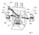
図4は、2つのツール・ホルダ122及び1つのワークピース・キャリア123を、モジュールの上に、たとえば、セット・アップ・モジュール又は機械加工モジュールの上に装着することを、概略的に示している。それぞれのツール・ホルダ122は、電動式の様式でその位置を移動及び補正することができるように、取り付けデバイス1223によって、モジュール110又は210のスライド(コーム)に取り付けられている。したがって、スライドに対するツール・ホルダ122の位置決めのエラー、又は、セット・アップ・マシンの上での位置決めに対する位置決めの差は、対応する様式でスライドの移動を修正することによって補償される。
FIG. 4 schematically illustrates mounting two
それぞれのツール・ホルダ122は、位置決め基準1221をさらに含み、たとえば、それに限定されないが、下記に開示されているように、ターゲット・キャリア1222の上に装着されている光学的なターゲットをさらに含む。有利には、マシンがいくつかのスライド(コーム)の上にいくつかのツール・ホルダ122を含むときに、いくつかの異なる位置決め基準が設けられることとなる。同様に、ワークピース・キャリア123は、取り付けデバイス1232によって装着されており、また、位置決め基準1231、たとえば、下記に詳述されている別の光学的なターゲットを含む。それぞれのツール・ホルダ及びワークピース・キャリアにリンクされた位置決め基準の相対的位置決めは、たとえば、フレームにリンクされたビジョン・システムによって制御され得、それは、位置決め基準1221と1231との間で、X軸及びY軸に沿って距離を測定することを可能にする。有利な実施形態では、システムは、所定の方向へのツール・ホルダ・スライド移動を制御し、イメージの中で測定される移動の実際の方向とターゲット方向との間の差シータを測定する。したがって、X軸及びY軸の直交性エラーを補償することを可能にする。
Each
セット・アップの間に使用された値に対応する、ツール・ホルダ及びワークピース・キャリアの相対的位置決め及び配向を機械加工の間に得るために、このように測定される位置決め及び移動の方向のエラーは、たとえば、前記ツール・ホルダの軸線によって補償される。 The direction of positioning and movement thus measured to obtain the relative positioning and orientation of the tool holder and workpiece carrier during machining, corresponding to the values used during set-up. The error is compensated by, for example, the axis of the tool holder.
図5は、2つの位置決め基準1221及び1231の部分的な断面の斜視図を示しており、2つの位置決め基準1221及び1231は、ツール・ホルダ及びワークピース・キャリアにそれぞれリンクされており、それらがモジュール110又は210のうちの1つの上に装着されるときに重ね合わせられる。モジュール110又は210のフレームにリンクされている固定位置決め制御デバイス121が、2つのターゲット1221及び1231の間の正しい相対的位置決めをチェックするために使用され得、また、セット・アップ・マシンの上で使用される位置決めに対するこの位置決めの任意のエラー又は差を補償するために使用され得る。位置決め制御デバイス121は、顕微鏡レンズを設けられたカメラから構成することが可能であり、又は、異なる重ね合わせられた光学的なターゲット1221及び1231のイメージをキャプチャすることができ、それらの相対的位置決めをチェックするようになっている光学的なシステムから構成することが可能である。したがって、コンピュータ化されたビジョン・システムが、距離x、y、及び、ターゲット1221と1231との間の移動方向シータのエラーを測定するために使用され得、前記エラーを補償するようになっている。
FIG. 5 shows a perspective view of a partial cross section of the two
また、あまり有利ではないが、ツール・ホルダ又はワークピース・キャリアに固定された位置決め制御デバイス、たとえば、カメラを設けるということも可能である。しかし、この解決策は、それぞれのツール・ホルダ又はキャリアに関して、制御デバイスを必要とする。 It is also possible, to a lesser extent, to provide a positioning control device, such as a camera, fixed to a tool holder or workpiece carrier. However, this solution requires a control device for each tool holder or carrier.
また、同様に、カウンタ・スピンドル125の上のワークピース・キャリアにリンクされたターゲットと、カウンタ動作で1つ又は複数のツール・ホルダにリンクされたターゲットとを設けることも可能であり、互いに対する、及び/又は、メイン・ワークピース・キャリア123に対する、これらのエレメントの位置決めを制御するようになっている。
Similarly, it is also possible to provide a target linked to a workpiece carrier on the
図6は、ワークピース・キャリア123(たとえば、ガイド・ブッシュ又はスピンドル)に関連付けられたターゲット1231と、1つ又は複数のツール・ホルダ122に関連付けられた1つ又は複数のターゲット1221との重ね合わせを概略的に示している。示されているように、ワークピース・キャリアに関連付けられたターゲット1231は、ガイド・ブッシュ123に対してオフセットされた位置に装着されており、それにもかかわらず、前記ターゲットの軸線は、ガイド・ブッシュの軸線と平行になっている。同様に、それぞれのツール・ホルダ122の上に装着されているターゲット1221は、ターゲット・キャリア1222によってオフセットされている。ツール・ホルダの位置補正デバイスは、モータ1224を含み、モータ1224には、エンコーダ1225が設けられており、エンコーダ1225は、X軸に沿って、それぞれのツール・ホルダの位置Xmを補正するために使用され得、機械加工の間にツール・ホルダを移動させ、ターゲット1221−1231の任意のX位置決めエラーを考慮するようになっている。同様に、エンコーダ1227を設けられたモータ1226が、Y軸に沿って、それぞれのツール・ホルダの位置Ymを修正するために使用され得、ターゲット1221−1231の任意のY位置決めエラーを補正するようになっている。エレメント1220は、X及びYに沿って移動可能なツール・ホルダの上のツール・グループであり、一方、前記ツール・ホルダの上に装着されているツールのうちの1つの先端部は、基準1228によって示されている。示されているように、ツール・ホルダの基準に対するこの先端部の位置は、コンピュータによって測定及び記憶され得る。また、X−Y平面における配向の補正が、予測され得る。
FIG. 6 shows a superposition of a
ターゲット1221及び1231は、たとえば、十字形状若しくは星形形状のパターンを含むことが可能であり、又は、線形のX軸及びY線に沿って、重ね合わせられたターゲットのアライメントをチェックすること、並びに、ワークピース・キャリアにリンクされている、座標規準系におけるターゲット1231の移動方向シータをチェックすることを助ける他のパターンを含むことが可能である。これらのパターンは、たとえば、ガラス基板の上のフォトリソグラフィーによってプリントされ得る。また、それぞれのターゲットに関する一意的な識別、たとえば、シリアル番号、バーコード、データグラムなどをプリントすることが可能であり、それぞれのターゲットを容易に識別するようになっており、したがって、前記ターゲットに関連付けられたツール・ホルダ又はワークピース・キャリアを容易に識別するようになっており、したがって、特定のワークピースがツール・ホルダ及び関連のワークピース・キャリアによって正しく機械加工されることを確実にする。また、一意的なツール・ホルダ識別は、数値制御1211のコンピュータ・メモリの中において、前記ツール・ホルダと関連付けられたパラメータ、たとえば、オフセット値、ゼロ値などを見出すために使用され得る。
図7は、位置決め検証システムの実施形態を概略的に示している。この例では、位置決め制御デバイスは、ターゲット1221及び1231の一方の側部に、顕微鏡レンズ1213及びCCDカメラ121を含み、ターゲットの他方の側部に、照明1212を含む。照明1212によって発生される光は、重ね合わせられたターゲットを通過し、CCDカメラ121に到達し、CCDカメラ121は、レンズ1213によって拡大されたイメージ又はイメージのシーケンスをキャプチャする。ビジョン・モジュール1210、たとえば、コンピュータ・プログラムは、ターゲットのアライメントをチェックするために、CCDカメラによってキャプチャされたイメージを処理する。このモジュールによって提供される結果は、数値制御1211に送信され得、数値制御1211は、セット・アップ・モジュール又は機械加工モジュールを制御し、また、モータ1226及び1224を制御するために使用され得、観察されるエラーを補償するように、機械加工の間に、1つ又は複数のツール・ホルダを移動させるようになっている。また、たとえば、マイクロメータ・スクリューを使用して、マニュアル位置補正メカニズムが実装され得る。変形例では、セット・アップ・モジュールの中の位置決めエラーは、補正されないか、又は、完全には補正されないが、問題のターゲットに関して記憶され、機械加工モジュールの上での生産の間にこのエラーを再現するようになっている。
FIG. 7 schematically shows an embodiment of the positioning verification system. In this example, the positioning control device includes a
図8は、位置決め検証システムの別の実施形態を概略的に示している。この例では、位置決め制御デバイスは、同軸の照明を備えた顕微鏡レンズ1214を含み、また、ターゲット1221及び1231に対して同じ側部にCCDカメラ121を含む。照明によって発生される光は、重ね合わせられたターゲットによって反射され、CCDカメラ121に到達し、CCDカメラ121は、レンズ1214によって拡大されたイメージ又はイメージのシーケンスをキャプチャする。上記のように、ビジョン・モジュール1210、たとえば、コンピュータ・プログラムは、ターゲットの位置決めをチェックするために、並びに、数値制御1211を介して補正を実施又は記憶するために、CCDカメラによってキャプチャされたイメージを処理する。
FIG. 8 schematically illustrates another embodiment of the positioning verification system. In this example, the positioning control device includes a
他の位置決め基準も、ワークピース・キャリアに対する1つ又は複数のツール・ホルダの位置決めをチェックするために予測され得る。非限定的な例として、容量式システム、誘導式システム、若しくは磁気抵抗システム、又は機械的なフィーラーが、このために実装され得る。 Other positioning criteria can also be predicted to check the positioning of one or more tool holders with respect to the workpiece carrier. As non-limiting examples, capacitive systems, inductive systems, or magnetoresistive systems, or mechanical feelers can be implemented for this purpose.
110 機械加工モジュール
112、212 保護カバー
112a 側壁部
112b 側壁部
112c 上部壁部
112d フレームにリンクされている底部壁部
112e 後方壁部
112f 前方壁部
114 エンクロージャ
120 機械加工アセンブリ
121 位置決め制御デバイス
1210 ビジョン・モジュール
1211 数値制御
1212 照明
1213 顕微鏡レンズ
1214 同軸の照明を備えたレンズ
122 取り外し可能なツール・ホルダ
1220 ツール・グループ
1221 ツール・ホルダの位置決め基準、たとえばターゲット
1222 ターゲット・キャリア
1223 ツール・ホルダ取り付けデバイス
1224 ツール・ホルダのX位置補正デバイス(モータ)
1225 モータ1224のエンコーダ
1226 ツール・ホルダのY位置補正デバイス(モータ)
1227 モータ1226のエンコーダ
1228 ツールのうちの1つの先端部
123 ワークピース・キャリア(ガイド・ブッシュ、マンドレル及び/又はクランプ)
1231 ワークピース・キャリアの位置決め基準、たとえばターゲット
1232 ワークピース・キャリア取り付けデバイス
124 スピンドル
125、225 カウンタ・スピンドル
126 サポート・ベース
127 機械加工されることとなるバーのマガジン
128、228 切粉トレイ
129 オイル・パン
130、230 移動可能なスライド
132 ガイドレール
140、240 ヒューム抽出煙突
142、242 信号ランプ
210 セット・アップ・モジュール
260 センサ又はカメラ
261 スクリーン
110
1225
1227
1231 Workpiece carrier positioning criteria, eg target 1232 Workpiece
Claims (18)
前記セット・アップ・モジュール(210)は、
*少なくとも1つのツール・ホルダ(122)を取り外し可能に取り付けるための少なくとも1つの第1のツール・ホルダ(122)取り付けデバイス(1223)と、ワークピース・キャリア(123)を取り外し可能に取り付けるための少なくとも1つの第1のワークピース・キャリア(123)取り付けデバイス(1232)とを含み、
前記機械加工モジュール(110)は、
*少なくとも1つのツール・ホルダ(122)を取り外し可能に取り付けるための少なくとも1つの第2のツール・ホルダ(122)取り付けデバイス(1223)と、ワークピース・キャリア(123)を取り外し可能に取り付けるための少なくとも1つの第2のワークピース・キャリア(123)取り付けデバイス(1232)とを含み、
*前記セット・アップ・モジュール(210)は、前記ワークピース・キャリア(123)に対する前記少なくとも1つのツール・ホルダ(122)の位置決めを制御するための第1の位置決め制御デバイス(121)をさらに含み、
*前記機械加工モジュール(110)は、前記ワークピース・キャリア(123)に対する前記少なくとも1つのツール・ホルダ(122)の位置決めをチェックするように適合された第2の位置決め制御デバイス(121)をさらに含み、前記ツール・ホルダ(122)及び前記ワークピース・キャリア(123)が、両方とも、セット・アップの後に、前記セット・アップ・モジュールから前記機械加工モジュールへ移送され得るようになっており、したがって、前記第2の位置決め制御デバイス(121)は、前記少なくとも1つのツール・ホルダ(122)と前記ワークピース・キャリア(123)との間の位置決めが、前記セット・アップ・モジュール(210)の上でのセット・アップの間に前記少なくとも1つのツール・ホルダ(122)と前記ワークピース・キャリア(123)との間に適用されたものと同一であるということを、前記機械加工モジュール(110)の上で確実にすることを可能にする、ワークピース機械加工システム。 A workpiece machining system that includes a set-up module (210) and a machining module (110) for creating workpieces.
The set-up module (210)
* For detachably mounting at least one first tool holder (122) mounting device (1223) and workpiece carrier (123) for detachably mounting at least one tool holder (122). Including at least one first workpiece carrier (123) mounting device (1232)
The machining module (110)
* For detachably attaching at least one second tool holder (122) mounting device (1223) and workpiece carrier (123) for detachably mounting at least one tool holder (122). Including at least one second workpiece carrier (123) mounting device (1232)
* The set-up module (210) further includes a first positioning control device (121) for controlling the positioning of the at least one tool holder (122) with respect to the workpiece carrier (123). ,
* The machining module (110) further includes a second positioning control device (121) adapted to check the positioning of the at least one tool holder (122) with respect to the workpiece carrier (123). Including, both the tool holder (122) and the workpiece carrier (123) can be transferred from the set-up module to the machining module after set-up. Therefore, in the second positioning control device (121), the positioning between the at least one tool holder (122) and the workpiece carrier (123) is performed by the set-up module (210). The machining module (110) is the same as that applied between the at least one tool holder (122) and the workpiece carrier (123) during the set-up above. ) Workpiece machining system that allows you to ensure on.
前記セット・アップ・モジュール(210)によって、前記機械加工プロセスをセット・アップするステップと、
少なくとも1つのツール・ホルダ(122)を、前記セット・アップ・モジュール(210)から、生産のために使用されることとなる機械加工モジュール(110)へ移送するステップとを含み、前記機械加工プロセスは、
ワークピース・キャリア(123)を、セット・アップ・モジュール(210)から、生産のために使用されることとなる機械加工モジュール(110)へ移送するステップと、
前記セット・アップ・モジュール(210)上及び前記機械加工モジュール(110)上での前記ワークピース・キャリア(123)及び1つ又は複数の前記ツール・ホルダ(122)の相対的位置決めをチェックするステップであって、前記セット・アップ・モジュール(210)の上でのセット・アップの間に前記少なくとも1つのツール・ホルダ(122)と前記ワークピース・キャリア(123)との間で適用されたものと同一の、前記少なくとも1つのツール・ホルダ(122)と前記ワークピース・キャリア(123)との間の位置決めを前記機械加工モジュール(110)の上で確実にするためにチェックするステップと、
前記ワークピース・キャリア(123)及び前記ツール・ホルダ(122)によって、前記機械加工モジュール(110)の上でワークピースを機械加工するステップとをさらに含む、機械加工プロセス。 A machining process for machining workpieces using a machining module (110) and a set-up module (210) to create a workpiece.
The step of setting up the machining process by the set-up module (210), and
The machining process includes the step of transferring at least one tool holder (122) from the set-up module (210) to the machining module (110) that will be used for production. Is
Steps to transfer the workpiece carrier (123) from the set-up module (210) to the machining module (110) that will be used for production.
A step of checking the relative positioning of the workpiece carrier (123) and one or more of the tool holders (122) on the set-up module (210) and on the machining module (110). And applied between the at least one tool holder (122) and the workpiece carrier (123) during set-up on the set-up module (210). The same step as checking to ensure positioning between the at least one tool holder (122) and the workpiece carrier (123) on the machining module (110).
A machining process further comprising the step of machining a workpiece on the machining module (110) by the workpiece carrier (123) and the tool holder (122).
Applications Claiming Priority (3)
| Application Number | Priority Date | Filing Date | Title |
|---|---|---|---|
| CH00831/15A CH711177A1 (en) | 2015-06-11 | 2015-06-11 | A workpiece machining system, a debugging module and a workpiece machining method. |
| CH00831/15 | 2015-06-11 | ||
| PCT/IB2016/053380 WO2016199044A2 (en) | 2015-06-11 | 2016-06-09 | Setting-up method and module, and workpiece machining system comprising a module of said type |
Publications (2)
| Publication Number | Publication Date |
|---|---|
| JP2018524194A JP2018524194A (en) | 2018-08-30 |
| JP6796640B2 true JP6796640B2 (en) | 2020-12-09 |
Family
ID=54148288
Family Applications (1)
| Application Number | Title | Priority Date | Filing Date |
|---|---|---|---|
| JP2018516650A Active JP6796640B2 (en) | 2015-06-11 | 2016-06-09 | Workpiece Machining Systems and Methods with Setup Modules |
Country Status (9)
| Country | Link |
|---|---|
| US (1) | US10293446B2 (en) |
| EP (1) | EP3307475B1 (en) |
| JP (1) | JP6796640B2 (en) |
| KR (1) | KR102561852B1 (en) |
| CN (1) | CN107949457B (en) |
| CH (1) | CH711177A1 (en) |
| ES (1) | ES2836675T3 (en) |
| RU (1) | RU2719967C2 (en) |
| WO (1) | WO2016199044A2 (en) |
Families Citing this family (4)
| Publication number | Priority date | Publication date | Assignee | Title |
|---|---|---|---|---|
| KR102274611B1 (en) | 2018-04-06 | 2021-07-06 | 주식회사 엘지에너지솔루션 | Lithium metal secondary battery with improved extended performances |
| DE102019105605A1 (en) * | 2018-07-11 | 2020-01-16 | Felder Kg | Arrangement comprising a CNC machining center |
| CN112605413B (en) * | 2020-12-16 | 2022-03-01 | 烟台艾迪锐能超硬刀具有限公司 | Ring feedback intelligent cutter system and use method thereof |
| US11833630B2 (en) | 2021-05-28 | 2023-12-05 | Yamazaki Mazak Corporation | Machine tool with removable workpiece support |
Family Cites Families (40)
| Publication number | Priority date | Publication date | Assignee | Title |
|---|---|---|---|---|
| DE1477657A1 (en) | 1964-07-08 | 1969-04-03 | Pittler Ag Maschf | Numerically controlled short lathe |
| US4369563A (en) * | 1965-09-13 | 1983-01-25 | Molins Limited | Automated machine tool installation with storage means |
| CH459709A (en) * | 1967-05-12 | 1968-07-15 | Tarex Sa | Machine tool simulator |
| GB1246796A (en) | 1967-09-15 | 1971-09-22 | Warner Swasey Asquith Ltd | Apparatus for setting cutting tools in machine tools |
| DE1602821A1 (en) | 1967-10-16 | 1970-08-27 | Monforts Fa A | Device on turret lathes for setting up the tools |
| US3867763A (en) * | 1969-07-07 | 1975-02-25 | Wickman Mach Tool Sales Ltd | Setting fixture for machine tools |
| JPS489487U (en) * | 1971-06-12 | 1973-02-02 | ||
| JPS5077112A (en) * | 1973-10-11 | 1975-06-24 | ||
| JPS5228743A (en) * | 1975-08-29 | 1977-03-03 | Nippon Steel Corp | High temperature materials cooling equipment |
| US4240207A (en) * | 1979-10-29 | 1980-12-23 | Erickson Tool Company | Tool presetting device |
| JPS59163438U (en) * | 1983-04-19 | 1984-11-01 | 株式会社 日研工作所 | Tool clamp presetter |
| CH665984A5 (en) * | 1984-03-09 | 1988-06-30 | Buechler B Set Ag | DEVICE FOR HOLDING AN OBJECT. |
| JPS6151203A (en) | 1984-08-18 | 1986-03-13 | Fanuc Ltd | Numerical control system |
| SU1296372A1 (en) * | 1985-01-31 | 1987-03-15 | Пензенский Завод-Втуз | Device for setting displacements |
| JPS6322224A (en) * | 1986-07-14 | 1988-01-29 | Matsushita Electric Works Ltd | Data preparing device for continuous electric discharge machining |
| JP3222178B2 (en) * | 1991-07-23 | 2001-10-22 | 三菱電機株式会社 | Electric discharge machine and electric discharge machine |
| JP2681323B2 (en) * | 1991-12-27 | 1997-11-26 | 三菱電機株式会社 | EDM machine |
| JPH08118175A (en) * | 1994-10-21 | 1996-05-14 | Imao Corp:Kk | Fitting base member and fixture fitted to this base member |
| US5595377A (en) * | 1995-06-06 | 1997-01-21 | Gaiser Tool Co. | Workpiece presetting assembly |
| US6230070B1 (en) * | 1997-07-23 | 2001-05-08 | Fuji Seiki Co., Ltd. | Work position adjusting apparatus and adjusting method |
| FR2768072B1 (en) * | 1997-09-08 | 1999-12-17 | E P B Emile Pfalzgraf | TOOL PRESET BALANCING MACHINE |
| JP2001030166A (en) * | 1999-07-23 | 2001-02-06 | Ntn Corp | Polishing equipment |
| DE10037532B4 (en) * | 1999-08-06 | 2008-09-11 | Prüftechnik Dieter Busch AG | Device for adjusting tools, workpieces or measuring devices on machine tools |
| JP2002346885A (en) | 2001-05-28 | 2002-12-04 | Matsushita Electric Works Ltd | Positioning method for machining |
| US6855099B2 (en) | 2001-10-31 | 2005-02-15 | The Boeing Company | Manufacturing system for aircraft structures and other large structures |
| ITMI20020267A1 (en) | 2002-02-12 | 2003-08-12 | Bavelloni Z Spa | AUTOMATIC MACHINE FOR THE PROCESSING OF SLAB MATERIALS, IN PARTICULAR GLASS SHEETS |
| DE10252086B4 (en) * | 2002-11-08 | 2007-03-29 | Reiden Technik Ag | Machine tool, in particular milling machine, and method for operating such a machine tool |
| DE10258734A1 (en) * | 2002-12-16 | 2004-06-24 | Alfing Kessler Sondermaschinen Gmbh | Machine tool for machining workpieces comprises a machining module, a mounting module, and a pallet-changing module coupled to the mounting module asymmetrically to the central plane |
| DE102004053503B4 (en) * | 2004-10-27 | 2015-06-18 | Nagel Maschinen- Und Werkzeugfabrik Gmbh | Honing system with several workstations |
| JP2006142419A (en) * | 2004-11-17 | 2006-06-08 | Imao Corporation:Kk | Mounting auxiliary base, positioning member and pallet of machine tool |
| DE102005047250A1 (en) * | 2005-10-01 | 2007-04-05 | Supfina Grieshaber Gmbh & Co. Kg | Production line for producing work pieces, has many machining cells which are positioned side by side in row and transport device for transporting work piece in or from machining cells |
| RU2374059C2 (en) * | 2005-06-22 | 2009-11-27 | Маус С.П.А. | Method of mechanical treatment, particularly drilling and turning of wheels from light alloy and installation for mechanical treatment, operating according to method |
| DE102007042288A1 (en) * | 2007-01-25 | 2008-09-25 | Mauser-Werke Oberndorf Maschinenbau Gmbh | Machine tool, has multiple tool spindle heads supported in machine rack and workpiece carrier, which is displaced along guidance and machine frame has closed frame with regard to force flow |
| CN201017521Y (en) * | 2007-03-21 | 2008-02-06 | 固高科技(深圳)有限公司 | Double coordinates processing module of aggregate machinery for teaching |
| JP5121466B2 (en) | 2008-01-10 | 2013-01-16 | シチズンマシナリーミヤノ株式会社 | Center height position adjusting device and center height position adjusting method |
| EP2192463B1 (en) | 2008-11-28 | 2014-03-05 | Klingelnberg AG | Device and method to position a symmetrically rotating precision part |
| DE202013002678U1 (en) * | 2013-02-05 | 2013-03-26 | Otto Bihler Handels-Beteiligungs-Gmbh | Production machine and mounting plate for the production machine |
| DE102013012633A1 (en) * | 2013-07-29 | 2015-01-29 | Alfing Kessler Sondermaschinen Gmbh | Machine tool with a workpiece changing device |
| CN104015230B (en) | 2014-06-23 | 2015-12-30 | 台州联帮机器人科技有限公司 | A kind of system of processing of surface of the work and processing method |
| CN106271748A (en) | 2016-09-28 | 2017-01-04 | 广州凯耀资产管理有限公司 | A kind of dismountable mechanical clamp for machining assembly and method of work thereof |
-
2015
- 2015-06-11 CH CH00831/15A patent/CH711177A1/en unknown
-
2016
- 2016-06-09 WO PCT/IB2016/053380 patent/WO2016199044A2/en active Application Filing
- 2016-06-09 KR KR1020187000857A patent/KR102561852B1/en active IP Right Grant
- 2016-06-09 EP EP16763938.4A patent/EP3307475B1/en active Active
- 2016-06-09 US US15/580,775 patent/US10293446B2/en active Active
- 2016-06-09 JP JP2018516650A patent/JP6796640B2/en active Active
- 2016-06-09 CN CN201680047129.5A patent/CN107949457B/en active Active
- 2016-06-09 ES ES16763938T patent/ES2836675T3/en active Active
- 2016-06-09 RU RU2018100120A patent/RU2719967C2/en active
Also Published As
| Publication number | Publication date |
|---|---|
| RU2018100120A (en) | 2019-07-11 |
| EP3307475A2 (en) | 2018-04-18 |
| ES2836675T3 (en) | 2021-06-28 |
| KR20180040566A (en) | 2018-04-20 |
| WO2016199044A3 (en) | 2017-02-16 |
| RU2719967C2 (en) | 2020-04-23 |
| US20180229340A1 (en) | 2018-08-16 |
| US10293446B2 (en) | 2019-05-21 |
| CN107949457A (en) | 2018-04-20 |
| CN107949457B (en) | 2019-11-22 |
| JP2018524194A (en) | 2018-08-30 |
| KR102561852B1 (en) | 2023-08-02 |
| CH711177A1 (en) | 2016-12-15 |
| EP3307475B1 (en) | 2020-09-30 |
| RU2018100120A3 (en) | 2019-10-17 |
| WO2016199044A2 (en) | 2016-12-15 |
Similar Documents
| Publication | Publication Date | Title |
|---|---|---|
| CN108136555B (en) | Machining module, attachment arrangement for a machining module and method for starting a machining module | |
| JP6796640B2 (en) | Workpiece Machining Systems and Methods with Setup Modules | |
| JP6037891B2 (en) | Tool shape measuring method and tool shape measuring device | |
| JP6103800B2 (en) | Component mounter | |
| EP3054756B1 (en) | Component mounting device and component mounting method | |
| JP2017144534A (en) | Work holder and processing system of using this work holder holding tool | |
| EP3275592B1 (en) | Machine tool | |
| US7543259B2 (en) | Method and device for deciding support portion position in a backup device | |
| JP5762514B2 (en) | Tool magazine device | |
| CN102756429A (en) | Ceramic-substrate-based high-precision automatic drilling machine | |
| JPH06262446A (en) | Assembling cell and aggregate thereof capable of mounting/removing part supplier | |
| JPS5994539A (en) | Positioning device for material to be worked in machine tool | |
| EP3021652B1 (en) | Method for allocating electronic components and electronic component mounting system | |
| JP4750792B2 (en) | Diagnostic tool for component feeder replacement | |
| JPH0799799B2 (en) | Electronic component automatic insertion machine | |
| DE102005035420A1 (en) | Modular device for loading substrates | |
| JPH0799800B2 (en) | How to enter the component insertion position of the automatic electronic component insertion machine |
Legal Events
| Date | Code | Title | Description |
|---|---|---|---|
| A521 | Request for written amendment filed |
Free format text: JAPANESE INTERMEDIATE CODE: A523 Effective date: 20180213 |
|
| A621 | Written request for application examination |
Free format text: JAPANESE INTERMEDIATE CODE: A621 Effective date: 20181015 |
|
| A977 | Report on retrieval |
Free format text: JAPANESE INTERMEDIATE CODE: A971007 Effective date: 20190830 |
|
| A131 | Notification of reasons for refusal |
Free format text: JAPANESE INTERMEDIATE CODE: A131 Effective date: 20190904 |
|
| A521 | Request for written amendment filed |
Free format text: JAPANESE INTERMEDIATE CODE: A523 Effective date: 20191121 |
|
| A131 | Notification of reasons for refusal |
Free format text: JAPANESE INTERMEDIATE CODE: A131 Effective date: 20200430 |
|
| A521 | Request for written amendment filed |
Free format text: JAPANESE INTERMEDIATE CODE: A523 Effective date: 20200527 |
|
| RD04 | Notification of resignation of power of attorney |
Free format text: JAPANESE INTERMEDIATE CODE: A7424 Effective date: 20200703 |
|
| TRDD | Decision of grant or rejection written | ||
| A01 | Written decision to grant a patent or to grant a registration (utility model) |
Free format text: JAPANESE INTERMEDIATE CODE: A01 Effective date: 20201021 |
|
| A61 | First payment of annual fees (during grant procedure) |
Free format text: JAPANESE INTERMEDIATE CODE: A61 Effective date: 20201116 |
|
| R150 | Certificate of patent or registration of utility model |
Ref document number: 6796640 Country of ref document: JP Free format text: JAPANESE INTERMEDIATE CODE: R150 |
|
| S111 | Request for change of ownership or part of ownership |
Free format text: JAPANESE INTERMEDIATE CODE: R313113 |
|
| R350 | Written notification of registration of transfer |
Free format text: JAPANESE INTERMEDIATE CODE: R350 |
|
| S111 | Request for change of ownership or part of ownership |
Free format text: JAPANESE INTERMEDIATE CODE: R313113 |
|
| R350 | Written notification of registration of transfer |
Free format text: JAPANESE INTERMEDIATE CODE: R350 |
|
| R250 | Receipt of annual fees |
Free format text: JAPANESE INTERMEDIATE CODE: R250 |