JP6795616B2 - PHY layer multiplexing of different types of traffic in 5G systems - Google Patents
PHY layer multiplexing of different types of traffic in 5G systems Download PDFInfo
- Publication number
- JP6795616B2 JP6795616B2 JP2018553122A JP2018553122A JP6795616B2 JP 6795616 B2 JP6795616 B2 JP 6795616B2 JP 2018553122 A JP2018553122 A JP 2018553122A JP 2018553122 A JP2018553122 A JP 2018553122A JP 6795616 B2 JP6795616 B2 JP 6795616B2
- Authority
- JP
- Japan
- Prior art keywords
- traffic
- traffic type
- symbol
- punctured
- type
- Prior art date
- Legal status (The legal status is an assumption and is not a legal conclusion. Google has not performed a legal analysis and makes no representation as to the accuracy of the status listed.)
- Active
Links
- 230000005540 biological transmission Effects 0.000 claims description 130
- 238000004891 communication Methods 0.000 claims description 67
- 238000000034 method Methods 0.000 claims description 16
- 238000012544 monitoring process Methods 0.000 claims 3
- 238000005516 engineering process Methods 0.000 description 19
- 238000010586 diagram Methods 0.000 description 16
- 238000007726 management method Methods 0.000 description 9
- 238000005192 partition Methods 0.000 description 9
- 230000011664 signaling Effects 0.000 description 9
- 238000013507 mapping Methods 0.000 description 7
- 230000006870 function Effects 0.000 description 6
- 241000700159 Rattus Species 0.000 description 4
- 230000001413 cellular effect Effects 0.000 description 4
- 238000013475 authorization Methods 0.000 description 3
- 230000015556 catabolic process Effects 0.000 description 3
- 238000006731 degradation reaction Methods 0.000 description 3
- 239000011159 matrix material Substances 0.000 description 3
- 230000002093 peripheral effect Effects 0.000 description 3
- 238000012546 transfer Methods 0.000 description 3
- 208000037918 transfusion-transmitted disease Diseases 0.000 description 3
- 101150014732 asnS gene Proteins 0.000 description 2
- 238000004590 computer program Methods 0.000 description 2
- 230000003111 delayed effect Effects 0.000 description 2
- 229910001416 lithium ion Inorganic materials 0.000 description 2
- 238000010295 mobile communication Methods 0.000 description 2
- QELJHCBNGDEXLD-UHFFFAOYSA-N nickel zinc Chemical compound [Ni].[Zn] QELJHCBNGDEXLD-UHFFFAOYSA-N 0.000 description 2
- 230000003287 optical effect Effects 0.000 description 2
- 238000012545 processing Methods 0.000 description 2
- 230000009467 reduction Effects 0.000 description 2
- 238000013468 resource allocation Methods 0.000 description 2
- 230000003595 spectral effect Effects 0.000 description 2
- 230000007480 spreading Effects 0.000 description 2
- HBBGRARXTFLTSG-UHFFFAOYSA-N Lithium ion Chemical compound [Li+] HBBGRARXTFLTSG-UHFFFAOYSA-N 0.000 description 1
- 230000003213 activating effect Effects 0.000 description 1
- 230000006978 adaptation Effects 0.000 description 1
- 230000003044 adaptive effect Effects 0.000 description 1
- 230000002776 aggregation Effects 0.000 description 1
- 238000004220 aggregation Methods 0.000 description 1
- 230000006399 behavior Effects 0.000 description 1
- 230000008901 benefit Effects 0.000 description 1
- OJIJEKBXJYRIBZ-UHFFFAOYSA-N cadmium nickel Chemical compound [Ni].[Cd] OJIJEKBXJYRIBZ-UHFFFAOYSA-N 0.000 description 1
- 239000003795 chemical substances by application Substances 0.000 description 1
- 125000004122 cyclic group Chemical group 0.000 description 1
- 238000013461 design Methods 0.000 description 1
- 238000001514 detection method Methods 0.000 description 1
- 230000008030 elimination Effects 0.000 description 1
- 238000003379 elimination reaction Methods 0.000 description 1
- 239000000446 fuel Substances 0.000 description 1
- 239000004973 liquid crystal related substance Substances 0.000 description 1
- 230000007774 longterm Effects 0.000 description 1
- 238000005259 measurement Methods 0.000 description 1
- 230000005055 memory storage Effects 0.000 description 1
- 229910052987 metal hydride Inorganic materials 0.000 description 1
- 230000008569 process Effects 0.000 description 1
- 239000004065 semiconductor Substances 0.000 description 1
- 238000001228 spectrum Methods 0.000 description 1
- 238000012384 transportation and delivery Methods 0.000 description 1
Images


Classifications
-
- H—ELECTRICITY
- H04—ELECTRIC COMMUNICATION TECHNIQUE
- H04L—TRANSMISSION OF DIGITAL INFORMATION, e.g. TELEGRAPHIC COMMUNICATION
- H04L5/00—Arrangements affording multiple use of the transmission path
- H04L5/003—Arrangements for allocating sub-channels of the transmission path
- H04L5/0058—Allocation criteria
- H04L5/0064—Rate requirement of the data, e.g. scalable bandwidth, data priority
-
- H—ELECTRICITY
- H04—ELECTRIC COMMUNICATION TECHNIQUE
- H04J—MULTIPLEX COMMUNICATION
- H04J11/00—Orthogonal multiplex systems, e.g. using WALSH codes
-
- H—ELECTRICITY
- H04—ELECTRIC COMMUNICATION TECHNIQUE
- H04L—TRANSMISSION OF DIGITAL INFORMATION, e.g. TELEGRAPHIC COMMUNICATION
- H04L27/00—Modulated-carrier systems
- H04L27/26—Systems using multi-frequency codes
- H04L27/2601—Multicarrier modulation systems
-
- H—ELECTRICITY
- H04—ELECTRIC COMMUNICATION TECHNIQUE
- H04L—TRANSMISSION OF DIGITAL INFORMATION, e.g. TELEGRAPHIC COMMUNICATION
- H04L27/00—Modulated-carrier systems
- H04L27/32—Carrier systems characterised by combinations of two or more of the types covered by groups H04L27/02, H04L27/10, H04L27/18 or H04L27/26
- H04L27/34—Amplitude- and phase-modulated carrier systems, e.g. quadrature-amplitude modulated carrier systems
- H04L27/3488—Multiresolution systems
-
- H—ELECTRICITY
- H04—ELECTRIC COMMUNICATION TECHNIQUE
- H04L—TRANSMISSION OF DIGITAL INFORMATION, e.g. TELEGRAPHIC COMMUNICATION
- H04L5/00—Arrangements affording multiple use of the transmission path
- H04L5/0001—Arrangements for dividing the transmission path
- H04L5/0003—Two-dimensional division
- H04L5/0005—Time-frequency
- H04L5/0007—Time-frequency the frequencies being orthogonal, e.g. OFDM(A), DMT
-
- H—ELECTRICITY
- H04—ELECTRIC COMMUNICATION TECHNIQUE
- H04L—TRANSMISSION OF DIGITAL INFORMATION, e.g. TELEGRAPHIC COMMUNICATION
- H04L5/00—Arrangements affording multiple use of the transmission path
- H04L5/003—Arrangements for allocating sub-channels of the transmission path
- H04L5/0048—Allocation of pilot signals, i.e. of signals known to the receiver
-
- H—ELECTRICITY
- H04—ELECTRIC COMMUNICATION TECHNIQUE
- H04L—TRANSMISSION OF DIGITAL INFORMATION, e.g. TELEGRAPHIC COMMUNICATION
- H04L5/00—Arrangements affording multiple use of the transmission path
- H04L5/0091—Signaling for the administration of the divided path
-
- H—ELECTRICITY
- H04—ELECTRIC COMMUNICATION TECHNIQUE
- H04L—TRANSMISSION OF DIGITAL INFORMATION, e.g. TELEGRAPHIC COMMUNICATION
- H04L1/00—Arrangements for detecting or preventing errors in the information received
- H04L1/004—Arrangements for detecting or preventing errors in the information received by using forward error control
- H04L1/0041—Arrangements at the transmitter end
-
- H—ELECTRICITY
- H04—ELECTRIC COMMUNICATION TECHNIQUE
- H04L—TRANSMISSION OF DIGITAL INFORMATION, e.g. TELEGRAPHIC COMMUNICATION
- H04L1/00—Arrangements for detecting or preventing errors in the information received
- H04L1/004—Arrangements for detecting or preventing errors in the information received by using forward error control
- H04L1/0045—Arrangements at the receiver end
-
- H—ELECTRICITY
- H04—ELECTRIC COMMUNICATION TECHNIQUE
- H04L—TRANSMISSION OF DIGITAL INFORMATION, e.g. TELEGRAPHIC COMMUNICATION
- H04L5/00—Arrangements affording multiple use of the transmission path
- H04L5/003—Arrangements for allocating sub-channels of the transmission path
- H04L5/0053—Allocation of signaling, i.e. of overhead other than pilot signals
-
- H—ELECTRICITY
- H04—ELECTRIC COMMUNICATION TECHNIQUE
- H04W—WIRELESS COMMUNICATION NETWORKS
- H04W72/00—Local resource management
- H04W72/12—Wireless traffic scheduling
- H04W72/1263—Mapping of traffic onto schedule, e.g. scheduled allocation or multiplexing of flows
-
- H—ELECTRICITY
- H04—ELECTRIC COMMUNICATION TECHNIQUE
- H04W—WIRELESS COMMUNICATION NETWORKS
- H04W84/00—Network topologies
- H04W84/02—Hierarchically pre-organised networks, e.g. paging networks, cellular networks, WLAN [Wireless Local Area Network] or WLL [Wireless Local Loop]
- H04W84/04—Large scale networks; Deep hierarchical networks
- H04W84/042—Public Land Mobile systems, e.g. cellular systems
Description
本発明は、5Gシステムにおける異なるタイプのトラフィックのPHYレイヤ多重化に関する。 The present invention relates to PHY layer multiplexing of different types of traffic in a 5G system.
関連出願の相互参照
本出願は、2016年4月8日に出願された米国特許仮出願第62/320080号、および2016年8月10日に出願された米国特許仮出願第62/373140号の利益を主張し、それらの内容は、参照によって本明細書に組み込まれ、本出願は、これらの優先出願の出願日の利益を主張する。
Mutual reference to related applications This application is of US Patent Provisional Application No. 62/320080 filed on April 8, 2016 and US Patent Provisional Application No. 62/373140 filed on August 10, 2016. Claiming interests, their contents are incorporated herein by reference, and this application claims the interests of the filing date of these preferred applications.
セルラ技術のための応用例の出現に伴い、より高いデータレート、より低い待ち時間(Low Latency)、および/または大規模な接続性をサポートする重要性は、おそらく高まり続けるであろう。例えば、拡張モバイルブロードバンド(eMBB)通信、ならびに/または超高信頼性および低待ち時間通信(URLLC:Ultra-Reliable and Low Latency Communication、超高信頼低遅延通信)に対するサポートが、例示的な使用シナリオ、および望ましい無線アクセス能力(access capability)とともに、ITUによって推奨されている。 With the advent of applications for cellular technology, the importance of supporting higher data rates, lower latency, and / or large connectivity will probably continue to grow. For example, support for extended mobile broadband (eMBB) communication and / or ultra-reliable and low latency communication (URLLC) is an exemplary use scenario. And recommended by the ITU, along with the desired access capability.
応用例および使用シナリオの範囲が広範になるのに伴い、無線アクセス能力は、その範囲内において、重要点が異なることがある。例えば、eMBBについては、スペクトル効率、容量、ユーザデータレート(例えば、ピークおよび/もしくは平均)、ならびに/またはモビリティが、高い重要性を有することができ、URLLC(超高信頼低遅延通信)については、ユーザプレーン待ち時間、および/または信頼性が、高い重要性を有することができる。異なる目標を有する複数の応用例が、サポートされるとき、無線アクセスネットワークにおいて、これらの応用例およびそれらのユーザを多重化するための効果的な手段を開発することは、ますます重要になるであろう。 As the range of applications and usage scenarios grows, wireless access capabilities may differ in importance within that range. For example, for eMBB, spectral efficiency, capacitance, user data rate (eg, peak and / or average), and / or mobility can be of high importance, and for URLLC (ultra-reliable low-latency communication). , User plane latency, and / or reliability can be of high importance. When multiple applications with different goals are supported, it will become increasingly important to develop effective means for multiplexing these applications and their users in radio access networks. There will be.
以下でより完全に説明される1つまたは複数の例示的な実施形態は、装置、機能、手順、プロセス、コンピュータ可読メモリを有形に具体化したコンピュータプログラム命令の実行、以下のうちの1つまたは複数についての方法の機能および動作を提供する。5Gシステムなどの無線通信システムにおける、異なるタイプのトラフィックの物理(PHY)レイヤ多重化のための、システム、方法および手段が、開示される。例においては、デバイス(例えば、WTRU)は、例えば、ネットワークから、通信(communication)を受信することができる。通信は、第1のトラフィックタイプ(例えば、待ち時間制約なしのトラフィック)を含むことができる。WTRUは、第1のトラフィックタイプと多重化された、および/または第1のトラフィックタイプをパンクチャした、第2のトラフィックタイプ(例えば、低待ち時間(低遅延)トラフィック)を通信が含むことを示すインジケーションを求めて通信を監視(monitor:モニター)することができる。監視(monitor)は、通信と関連付けられた制御チャネルの監視であることができる。WTRUは、インジケーションを求めて通信のロケーションを監視(monitor:モニター)することができる。例えば、WTRUは、通信の最後、シンボル、および/またはサブキャリアなどにおいて、インジケーションを求めて監視することができる。通信において受信され、監視によって検出されたインジケータは、第2のトラフィックタイプが通信内のどこに配置されているかを示すこと(例えば、示す情報を含むこと)ができる。第1のトラフィックタイプおよび第2のトラフィックタイプは、リソース要素(RE)レベルにおいて、多重化することができる。例えば、第1のトラフィックタイプは、REレベルにおいて、第2のトラフィックタイプによってパンクチャすることができる。1つまたは複数のパンクチャリングパターンを、使用することができる。WTRUは、インジケーションに基づいて、通信内の第1または第2のトラフィックタイプのうちの1つまたは複数をデコードすることができる。 One or more exemplary embodiments, more fully described below, are devices, functions, procedures, processes, execution of computer program instructions that tangibly embody computer-readable memory, or one or more of the following: Provides the functionality and behavior of multiple methods. Systems, methods and means for physical (PHY) layer multiplexing of different types of traffic in wireless communication systems such as 5G systems are disclosed. In the example, the device (eg, WTRU) can receive communication, for example, from a network. Communication can include a first type of traffic (eg, traffic with no latency constraints). WTRU indicates that the communication includes a second traffic type (eg, low latency (low latency) traffic) that is multiplexed with the first traffic type and / or punctured the first traffic type. Communication can be monitored for indications. A monitor can be a monitor of a control channel associated with a communication. The WTRU can monitor the location of communications for indications. For example, the WTRU can seek and monitor indications at the end of communication, symbols, and / or subcarriers and the like. Indicators received in the communication and detected by the monitor can indicate where in the communication the second traffic type is located (eg, include information to indicate). The first traffic type and the second traffic type can be multiplexed at the resource element (RE) level. For example, the first traffic type can be punctured by the second traffic type at the RE level. One or more puncturing patterns can be used. The WTRU can decode one or more of the first or second traffic types in the communication based on the encoding.
送信機(例えば、送信WTRU)は、送信するための低待ち時間(低遅延)データを受け取ることができる。低待ち時間(低遅延)データは、超高信頼性および低待ち時間(URLLC:超高信頼低遅延通信)データを含むことができる。送信機は、低待ち時間(低遅延)データに対して、リソースのプールを割り当てることができる。リソースのプールは、公称データ(nominal data)のための1つまたは複数のリソースを含むことができる。低待ち時間(低遅延)データと関連付けられた低待ち時間基準信号(reference signal)を、送信することができる。送信機は、低待ち時間データの送信のために、リソースのプールから、1つまたは複数の時間および/または周波数リソースを選択することができる。送信機は、選択されたリソースを使用して、低待ち時間データを送信することができる。低待ち時間(低遅延)データ送信は、例えば、公称データのための1つまたは複数のリソースを避けるように、パンクチャすることができる。送信機は、低待ち時間(低遅延)データの基準シンボルを、公称データの基準シンボルとアラインすることができる。 The transmitter (eg, transmit WTRU) can receive low latency (low latency) data for transmission. The low latency (low latency) data can include ultra-high reliability and low latency (URLLC: ultra-high reliability low latency communication) data. The transmitter can allocate a pool of resources for low latency (low latency) data. A pool of resources can contain one or more resources for nominal data. A low latency reference signal associated with low latency (low latency) data can be transmitted. The transmitter can select one or more time and / or frequency resources from the pool of resources for transmission of low latency data. The transmitter can use the selected resource to send low latency data. Low latency (low latency) data transmissions can be punctured, for example, to avoid one or more resources for nominal data. The transmitter can align the reference symbol for low latency (low latency) data with the reference symbol for nominal data.
説明的な実施形態についての詳細な説明が、様々な図を参照して、今から行われる。この説明は、可能な実施の詳細な例を提供するが、詳細は、例示的であることが意図されており、決して本出願の範囲を限定しないことに留意されたい。 A detailed description of the descriptive embodiment will now be given with reference to the various figures. It should be noted that this description provides detailed examples of possible practices, but the details are intended to be exemplary and by no means limit the scope of this application.
図1Aは、1つまたは複数の開示される実施形態を実施することができる、例示的な通信システム100の図である。通信システム100は、音声、データ、ビデオ、メッセージング、放送などのコンテンツを複数の無線ユーザに提供する、多元接続システムとすることができる。通信システム100は、複数の無線ユーザが、無線帯域幅を含むシステムリソースの共用を通して、そのようなコンテンツにアクセスすることを可能することができる。例えば、通信システム100は、符号分割多元接続(CDMA)、時分割多元接続(TDMA)、周波数分割多元接続(FDMA)、直交FDMA(OFDMA)、およびシングルキャリアFDMA(SC−FDMA)など、1つまたは複数のチャネルアクセス方法を利用することができる。
FIG. 1A is a diagram of an
図1Aに示されるように、通信システム100は、無線送受信ユニット(WTRU)102a、102b、102c、および/または102d(全体として、または一括して、WTRU102と呼ばれることがある)、無線アクセスネットワーク(RAN)103/104/105、コアネットワーク106/107/109、公衆交換電話網(PSTN)108、インターネット110、ならびに他のネットワーク112を含むことができるが、開示される実施形態は、任意の数のWTRU、基地局、ネットワーク、および/またはネットワーク要素を企図していることが理解されよう。WTRU102a、102b、102c、102dの各々は、無線環境において動作および/または通信するように構成された、任意のタイプのデバイスとすることができる。例として、WTRU102a、102b、102c、102dは、無線信号を送信および/または受信するように構成することができ、ユーザ機器(UE)、移動局、固定もしくは移動加入者ユニット、ページャ、セルラ電話、携帯情報端末(PDA)、スマートフォン、ラップトップ、ネットブック、パーソナルコンピュータ、無線センサ、および家電製品などを含むことができる。
As shown in FIG. 1A, the
通信システム100は、基地局114aおよび基地局114bも含むことができる。基地局114a、114bの各々は、WTRU102a、102b、102c、102dのうちの少なくとも1つと無線でインターフェース接続して、コアネットワーク106/107/109、インターネット110、および/またはネットワーク112などの1つまたは複数の通信ネットワークへのアクセスを容易にするように構成された、任意のタイプのデバイスとすることができる。例として、基地局114a、114bは、基地送受信機局(BTS)、ノードB、eノードB、ホームノードB、ホームeノードB、サイトコントローラ、アクセスポイント(AP)、および無線ルータなどとすることができる。基地局114a、114bは、各々が、単一の要素として示されているが、基地局114a、114bは、任意の数の相互接続された基地局および/またはネットワーク要素を含むことができることが理解されよう。
基地局114aは、RAN103/104/105の部分とすることができ、RAN103/104/105は、他の基地局、および/または基地局コントローラ(BSC)、無線ネットワークコントローラ(RNC)、中継ノードなどのネットワーク要素(図示されず)も含むことができる。基地局114aおよび/または基地局114bは、セル(図示されず)と呼ばれることがある、特定の地理的領域内において無線信号を送信および/または受信するように構成することができる。セルは、さらにセルセクタに分割することができる。例えば、基地局114aに関連付けられたセルは、3つのセクタに分割することができる。したがって、一実施形態においては、基地局114aは、送受信機を3つ、例えば、セルのセクタ毎に1つずつ含むことができる。別の実施形態においては、基地局114aは、多入力多出力(MIMO)技術を利用することができ、したがって、セルのセクタ毎に複数の送受信機を利用することができる。
基地局114a、114bは、エアインターフェース115/116/117上において、WTRU102a、102b、102c、102dのうちの1つまたは複数と通信することができ、エアインターフェース115/116/117は、任意の適切な無線通信リンク(例えば、無線周波(RF)、マイクロ波、赤外線(IR)、紫外線(UV)、可視光など)とすることができる。エアインターフェース115/116/117は、任意の適切な無線アクセス技術(RAT)を使用して確立することができる。
より具体的には、上で言及されたように、通信システム100は、多元接続システムとすることができ、CDMA、TDMA、FDMA、OFDMA、およびSC−FDMAなどの、1つまたは複数のチャネルアクセス方式を利用することができる。例えば、RAN103/104/105内の基地局114a、およびWTRU102a、102b、102cは、広帯域CDMA(WCDMA)を使用してエアインターフェース115/116/117を確立することができる、ユニバーサル移動体通信システム(UMTS)地上無線アクセス(UTRA)などの無線技術を実施することができる。WCDMAは、高速パケットアクセス(HSPA)および/または進化型HSPA(HSPA+)などの通信プロトコルを含むことができる。HSPAは、高速ダウンリンクパケットアクセス(HSDPA)および/または高速アップリンクパケットアクセス(HSUPA)を含むことができる。
More specifically, as mentioned above, the
別の実施形態においては、基地局114a、およびWTRU102a、102b、102cは、ロングタームエボリューション(LTE)および/またはLTEアドバンスト(LTE−A)を使用してエアインターフェース115/116/117を確立することができる、進化型UMTS地上無線アクセス(E−UTRA)などの無線技術を実施することができる。
In another embodiment, the
他の実施形態においては、基地局114a、およびWTRU102a、102b、102cは、IEEE802.16(例えば、マイクロ波アクセス用の世界的相互運用性(WiMAX))、CDMA2000、CDMA2000 1X、CDMA2000 EV−DO、暫定標準2000(IS−2000)、暫定標準95(IS−95)、暫定標準856(IS−856)、移動体通信用グローバルシステム(GSM)、GSMエボリューション用の高速データレート(EDGE)、およびGSM EDGE(GERAN)などの無線技術を実施することができる。
In other embodiments,
図1Aの基地局114bは、例えば、無線ルータ、ホームノードB、ホームeノードB、またはアクセスポイントとすることができ、職場、家庭、乗物、およびキャンパスなどの局所的エリアにおける無線接続性を容易にするために、任意の適切なRATを利用することができる。一実施形態においては、基地局114b、およびWTRU102c、102dは、IEEE802.11などの無線技術を実施して、無線ローカルエリアネットワーク(WLAN)を確立することができる。別の実施形態においては、基地局114b、およびWTRU102c、102dは、IEEE802.15などの無線技術を実施して、無線パーソナルエリアネットワーク(WPAN)を確立することができる。また別の実施形態においては、基地局114b、およびWTRU102c、102dは、セルラベースのRAT(例えば、WCDMA、CDMA2000、GSM、LTE、LTE−Aなど)を利用して、ピコセルまたはフェムトセルを確立することができる。図1Aに示されるように、基地局114bは、インターネット110への直接的な接続を有することがある。したがって、基地局114bは、コアネットワーク106/107/109を介してインターネット110にアクセスする必要がないことがある。
The
RAN103/104/105は、コアネットワーク106/107/109と通信することができ、コアネットワーク106/107/109は、音声、データ、アプリケーション、および/またはボイスオーバインターネットプロトコル(VoIP)サービスをWTRU102a、102b、102c、102dのうちの1つまたは複数に提供するように構成された、任意のタイプのネットワークとすることができる。例えば、コアネットワーク106/107/109は、呼制御、請求サービス、モバイルロケーションベースのサービス、プリペイド通話、インターネット接続性、ビデオ配信などを提供することができ、および/またはユーザ認証など、高レベルのセキュリティ機能を実行することができる。図1Aには示されていないが、RAN103/104/105および/またはコアネットワーク106/107/109は、RAN103/104/105と同じRATまたは異なるRATを利用する他のRANと直接的または間接的に通信することができることが理解されよう。例えば、E−UTRA無線技術を利用することができるRAN103/104/105に接続するのに加えて、コアネットワーク106/107/109は、GSM無線技術を利用する別のRAN(図示されず)とも通信することができる。
RAN103 / 104/105 can communicate with
コアネットワーク106/107/109は、PSTN108、インターネット110、および/または他のネットワーク112にアクセスするための、WTRU102a、102b、102c、102dのためのゲートウェイとしての役割も果たすことができる。PSTN108は、基本電話サービス(POTS)を提供する回線交換電話網を含むことができる。インターネット110は、TCP/IPインターネットプロトコルスイート内の伝送制御プロトコル(TCP)、ユーザデータグラムプロトコル(UDP)、およびインターネットプロトコル(IP)など、共通の通信プロトコルを使用する、相互接続されたコンピュータネットワークおよびデバイスからなるグローバルシステムを含むことができる。ネットワーク112は、他のサービスプロバイダによって所有および/または運営される有線または無線通信ネットワークを含むことができる。例えば、ネットワーク112は、RAN103/104/105と同じRATまたは異なるRATを利用することができる1つまたは複数のRANに接続された、別のコアネットワークを含むことができる。
通信システム100内のWTRU102a、102b、102c、102dのいくつかまたはすべては、マルチモード機能を含むことができ、例えば、WTRU102a、102b、102c、102dは、異なる無線リンク上で異なる無線ネットワークと通信するための複数の送受信機を含むことができる。例えば、図1Aに示されるWTRU102cは、セルラベースの無線技術を利用することができる基地局114aと通信するように、またIEEE802無線技術を利用することができる基地局114bと通信するように構成することができる。
Some or all of the
図1Bは、例示的なWTRU102のシステム図である。図1Bに示されるように、WTRU102は、プロセッサ118と、送受信機120と、送信/受信要素122と、スピーカ/マイクロフォン124と、キーパッド126と、ディスプレイ/タッチパッド128と、非リムーバブルメモリ130と、リムーバブルメモリ132と、電源134と、全地球測位システム(GPS)チップセット136と、他の周辺機器138とを含むことができる。WTRU102は、実施形態との整合性を保ちながら、上記の要素の任意のサブコンビネーションを含むことができることが理解されよう。また、実施形態は、基地局114a、114b、ならびに/またはとりわけ、送受信機局(BTS)、ノードB、サイトコントローラ、アクセスポイント(AP)、ホームノードB、進化型ノードB(eNodeB)、ホーム進化型ノードB(HeNB)、ホーム進化型ノードBゲートウェイ、およびプロキシノードなどの、しかしそれらに限定されない、基地局114a、114bが代表することができるノードが、図1Bにおいて示され、本明細書において説明される要素のいくつかまたはすべてを含むことができることを企図している。
FIG. 1B is an exemplary WTRU102 system diagram. As shown in FIG. 1B, the WTRU 102 includes a processor 118, a transmitter /
プロセッサ118は、汎用プロセッサ、専用プロセッサ、従来型プロセッサ、デジタル信号プロセッサ(DSP)、複数のマイクロプロセッサ、DSPコアと連携する1つまたは複数のマイクロプロセッサ、コントローラ、マイクロコントローラ、特定用途向け集積回路(ASIC)、フィールドプログラマブルゲートアレイ(FPGA)回路、他の任意のタイプの集積回路(IC)、および状態機械などとすることができる。プロセッサ118は、信号符号化、データ処理、電力制御、入力/出力処理、および/またはWTRU102が無線環境で動作することを可能にする他の任意の機能性を実行することができる。プロセッサ118は、送受信機120に結合することができ、送受信機120は、送信/受信要素122に結合することができる。図1Bは、プロセッサ118と送受信機120を別個の構成要素として示しているが、プロセッサ118と送受信機120は、電子パッケージまたはチップ内に一緒に統合することができることが理解されよう。
The processor 118 is a general purpose processor, a dedicated processor, a conventional processor, a digital signal processor (DSP), a plurality of microprocessors, one or more microprocessors working with a DSP core, a controller, a microcontroller, and an application specific integrated circuit (SP). It can be an ASIC), a field programmable gate array (FPGA) circuit, any other type of integrated circuit (IC), a state machine, and the like. Processor 118 can perform signal coding, data processing, power control, input / output processing, and / or any other functionality that allows the WTRU 102 to operate in a wireless environment. The processor 118 can be coupled to the transmitter /
送信/受信要素122は、エアインターフェース115/116/117上において、基地局(例えば、基地局114a)に信号を送信し、または基地局から信号を受信するように構成することができる。例えば、一実施形態においては、送信/受信要素122は、RF信号を送信および/または受信するように構成されたアンテナとすることができる。別の実施形態においては、送信/受信要素122は、例えば、IR、UV、または可視光信号を送信および/または受信するように構成された放射器/検出器とすることができる。また別の実施形態においては、送信/受信要素122は、RF信号および光信号の両方を送信および受信するように構成することができる。送信/受信要素122は、無線信号の任意の組み合わせを送信および/または受信するように構成することができることが理解されよう。
The transmit / receive element 122 can be configured to transmit or receive a signal from a base station (eg,
加えて、図1Bにおいては、送信/受信要素122は単一の要素として示されているが、WTRU102は、任意の数の送信/受信要素122を含むことができる。より具体的には、WTRU102は、MIMO技術を利用することができる。したがって、一実施形態においては、WTRU102は、エアインターフェース115/116/117上において無線信号を送信および受信するための2つ以上の送信/受信要素122(例えば、複数のアンテナ)を含むことができる。
In addition, in FIG. 1B, the transmit / receive element 122 is shown as a single element, but the WTRU 102 can include any number of transmit / receive elements 122. More specifically, WTRU102 can utilize MIMO technology. Thus, in one embodiment, the WTRU 102 may include two or more transmit / receive elements 122 (eg, a plurality of antennas) for transmitting and receiving radio signals on the
送受信機120は、送信/受信要素122によって送信されることになる信号を変調し、送信/受信要素122によって受信された信号を復調するように構成することができる。上で言及されたように、WTRU102は、マルチモード機能を有することができる。したがって、送受信機120は、WTRU102が、例えば、UTRAおよびIEEE802.11など、複数のRATを介して通信することを可能にするための、複数の送受信機を含むことができる。
The transmitter /
WTRU102のプロセッサ118は、スピーカ/マイクロフォン124、キーパッド126、および/またはディスプレイ/タッチパッド128(例えば、液晶表示(LCD)ディスプレイユニットもしくは有機発光ダイオード(OLED)ディスプレイユニット)に結合することができ、それらからユーザ入力データを受信することができる。プロセッサ118は、スピーカ/マイクロフォン124、キーパッド126、および/またはディスプレイ/タッチパッド128にユーザデータを出力することもできる。加えて、プロセッサ118は、非リムーバブルメモリ130および/またはリムーバブルメモリ132など、任意のタイプの適切なメモリから情報を入手することができ、それらにデータを記憶することができる。非リムーバブルメモリ130は、ランダムアクセスメモリ(RAM)、リードオンリメモリ(ROM)、ハードディスク、または他の任意のタイプのメモリ記憶デバイスを含むことができる。リムーバブルメモリ132は、加入者識別モジュール(SIM)カード、メモリスティック、およびセキュアデジタル(SD)メモリカードなどを含むことができる。他の実施形態においては、プロセッサ118は、サーバまたはホームコンピュータ(図示されず)上などに配置された、WTRU102上に物理的に配置されていないメモリから情報を入手することができ、それらにデータを記憶することができる。 The processor 118 of the WTRU 102 can be coupled to a speaker / microphone 124, a keypad 126, and / or a display / touchpad 128 (eg, a liquid crystal display (LCD) display unit or an organic light emitting diode (OLED) display unit). User input data can be received from them. The processor 118 can also output user data to the speaker / microphone 124, keypad 126, and / or display / touchpad 128. In addition, processor 118 can obtain information from any type of suitable memory, such as non-removable memory 130 and / or removable memory 132, and can store data in them. The non-removable memory 130 can include random access memory (RAM), read-only memory (ROM), hard disk, or any other type of memory storage device. The removable memory 132 can include a subscriber identification module (SIM) card, a memory stick, a secure digital (SD) memory card, and the like. In other embodiments, processor 118 can obtain information from memory that is not physically located on WTRU 102, such as on a server or home computer (not shown), and data on them. Can be memorized.
プロセッサ118は、電源134から電力を受け取ることができ、WTRU102内の他の構成要素への電力の分配および/または制御を行うように構成することができる。電源134は、WTRU102に給電するための任意の適切なデバイスとすることができる。例えば、電源134は、1つまたは複数の乾電池(例えば、ニッケル−カドミウム(NiCd)、ニッケル−亜鉛(NiZn)、ニッケル水素(NiMH)、リチウムイオン(Li−ion)など)、太陽電池、および燃料電池などを含むことができる。 Processor 118 can receive power from power supply 134 and can be configured to distribute and / or control power to other components within WTRU 102. The power supply 134 can be any suitable device for powering the WTRU 102. For example, the power supply 134 may be one or more batteries (eg, nickel-cadmium (NiCd), nickel-zinc (NiZn), nickel-metal hydride (NiMH), lithium-ion (Li-ion), etc.), solar cells, and fuel. It can include batteries and the like.
プロセッサ118は、GPSチップセット136に結合することもでき、GPSチップセット136は、WTRU102の現在ロケーションに関するロケーション情報(例えば、経度および緯度)を提供するように構成することができる。GPSチップセット136からの情報に加えて、またはその代わりに、WTRU102は、基地局(例えば、基地局114a、114b)からエアインターフェース115/116/117上においてロケーション情報を受信することができ、および/または2つ以上の近くの基地局から受信している信号のタイミングに基づいて、自らのロケーションを決定することができる。WTRU102は、実施形態との整合性を保ちながら、任意の適切なロケーション決定方法を用いて、ロケーション情報を獲得することができることが理解されよう。
Processor 118 can also be coupled to GPS chipset 136, which can be configured to provide location information (eg, longitude and latitude) regarding the current location of WTRU102. In addition to, or instead of, information from the GPS chipset 136, WTRU102 can receive location information from base stations (eg,
プロセッサ118は、他の周辺機器138にさらに結合することができ、他の周辺機器138は、追加的な特徴、機能性、および/または有線もしくは無線接続性を提供する、1つまたは複数のソフトウェアモジュールおよび/またはハードウェアモジュールを含むことができる。例えば、周辺機器138は、加速度計、eコンパス、衛星送受信機、(写真またはビデオ用の)デジタルカメラ、ユニバーサルシリアルバス(USB)ポート、バイブレーションデバイス、テレビ送受信機、ハンズフリーヘッドセット、Bluetooth(登録商標)モジュール、周波数変調(FM)ラジオユニット、デジタル音楽プレーヤ、メディアプレーヤ、ビデオゲームプレーヤモジュール、およびインターネットブラウザなどを含むことができる。 Processor 118 can be further coupled to other peripheral device 138, which is one or more software that provides additional features, functionality, and / or wired or wireless connectivity. Modules and / or hardware modules can be included. For example, peripherals 138 include accelerometers, e-compasses, satellite transmitters and receivers, digital cameras (for photos or videos), universal serial bus (USB) ports, vibration devices, television transmitters and receivers, hands-free headsets, Bluetooth (registered). It can include modules), frequency modulation (FM) radio units, digital music players, media players, video game player modules, Internet browsers, and the like.
図1Cは、実施形態による、RAN103およびコアネットワーク106のシステム図である。上で言及されたように、RAN103は、UTRA無線技術を利用して、エアインターフェース115上においてWTRU102a、102b、102cと通信することができる。RAN103は、コアネットワーク106と通信することもできる。図1Cに示されるように、RAN103は、ノードB140a、140b、140cを含むことができ、ノードB140a、140b、140cは、各々が、エアインターフェース115上においてWTRU102a、102b、102cと通信するための1つまたは複数の送受信機を含むことができる。ノードB140a、140b、140cは、各々、RAN103内の特定のセル(図示されず)に関連付けることができる。RAN103は、RNC142a、142bを含むこともできる。RAN103は、実施形態との整合性を保ちながら、任意の数のノードBおよびRNCを含むことができることが理解されよう。
FIG. 1C is a system diagram of the
図1Cに示されるように、ノードB140a、140bは、RNC142aと通信することができる。加えて、ノードB140cは、RNC142bと通信することができる。ノードB140a、140b、140cは、Iubインターフェースを介して、それぞれのRNC142a、142bと通信することができる。RNC142a、142bは、Iurインターフェースを介して、互いに通信することができる。RNC142a、142bの各々は、それが接続されたそれぞれのノードB140a、140b、140cを制御するように構成することができる。加えて、RNC142a、142bの各々は、アウタループ電力制御、負荷制御、アドミッションコントロール、パケットスケジューリング、ハンドオーバ制御、マクロダイバーシティ、セキュリティ機能、およびデータ暗号化など、他の機能性を実施またはサポートするように構成することができる。
As shown in FIG. 1C, the nodes B140a, 140b can communicate with the RNC142a. In addition, node B140c can communicate with RNC142b. Nodes B140a, 140b, 140c can communicate with their
図1Cに示されるコアネットワーク106は、メディアゲートウェイ(MGW)144、モバイル交換センタ(MSC)146、サービングGPRSサポートノード(SGSN)148、および/またはゲートウェイGPRSサポートノード(GGSN)150を含むことができる。上記の要素の各々は、コアネットワーク106の部分として示されているが、これらの要素のうちのいずれの1つも、コアネットワークオペレータとは異なるエンティティによって所有および/または運営することができることが理解されよう。
The
RAN103内のRNC142aは、IuCSインターフェースを介して、コアネットワーク106内のMSC146に接続することができる。MSC146は、MGW144に接続することができる。MSC146およびMGW144は、PSTN108などの回線交換ネットワークへのアクセスをWTRU102a、102b、102cに提供して、WTRU102a、102b、102cと従来の陸線通信デバイスとの間の通信を容易にすることができる。
The
RAN103内のRNC142aは、IuPSインターフェースを介して、コアネットワーク106内のSGSN148に接続することもできる。SGSN148は、GGSN150に接続することができる。SGSN148とGGSN150は、インターネット110などのパケット交換ネットワークへのアクセスをWTRU102a、102b、102cに提供して、WTRU102a、102b、102cとIP対応デバイスとの間の通信を容易にすることができる。
The
上で言及されたように、コアネットワーク106は、ネットワーク112に接続することもでき、ネットワーク112は、他のサービスプロバイダによって所有および/または運営される他の有線または無線ネットワークを含むことができる。
As mentioned above, the
図1Dは、実施形態による、RAN104およびコアネットワーク107のシステム図である。上で言及されたように、RAN104は、E−UTRA無線技術を利用して、エアインターフェース116上においてWTRU102a、102b、102cと通信することができる。RAN104は、コアネットワーク107と通信することもできる。
FIG. 1D is a system diagram of the
RAN104は、eノードB160a、160b、160cを含むことができるが、RAN104は、実施形態との整合性を保ちながら、任意の数のeノードBを含むことができることが理解されよう。eノードB160a、160b、160cは、各々が、エアインターフェース116上においてWTRU102a、102b、102cと通信するための1つまたは複数の送受信機を含むことができる。一実施形態においては、eノードB160a、160b、160cは、MIMO技術を実施することができる。したがって、eノードB160aは、例えば、複数のアンテナを使用して、WTRU102aに無線信号を送信し、WTRU102aから無線信号を受信することができる。
It will be appreciated that the
eノードB160a、160b、160cの各々は、特定のセル(図示されず)に関連付けることができ、無線リソース管理決定、ハンドオーバ決定、ならびにアップリンクおよび/またはダウンリンクにおけるユーザのスケジューリングなどを処理するように構成することができる。図1Dに示されるように、eノードB160a、160b、160cは、X2インターフェース上において互いに通信することができる。 Each of the e-nodes B160a, 160b, 160c can be associated with a particular cell (not shown) to handle radio resource management decisions, handover decisions, and user scheduling on uplinks and / or downlinks. Can be configured in. As shown in FIG. 1D, the e-nodes B160a, 160b, 160c can communicate with each other on the X2 interface.
図1Dに示されるコアネットワーク107は、モビリティ管理ゲートウェイ(MME)162と、サービングゲートウェイ164と、パケットデータネットワーク(PDN)ゲートウェイ166とを含むことができる。上記の要素の各々は、コアネットワーク107の部分として示されているが、これらの要素のうちのいずれの1つも、コアネットワークオペレータとは異なるエンティティによって所有および/または運営することができることが理解されよう。
The
MME162は、S1インターフェースを介して、RAN104内のeノードB160a、160b、160cの各々に接続することができ、制御ノードとしての役割を果たすことができる。例えば、MME162は、WTRU102a、102b、102cのユーザの認証、ベアラアクティブ化/非アクティブ化、WTRU102a、102b、102cの初期接続中における特定のサービングゲートウェイの選択などを担うことができる。MME162は、RAN104と、GSMまたはWCDMAなどの他の無線技術を利用する他のRAN(図示されず)との間の交換のためのコントロールプレーン機能を提供することもできる。
The
サービングゲートウェイ164は、S1インターフェースを介して、RAN104内のeノードB160a、160b、160cの各々に接続することができる。サービングゲートウェイ164は、一般に、ユーザデータパケットのWTRU102a、102b、102cへの/からのルーティングおよび転送を行うことができる。サービングゲートウェイ164は、eノードB間ハンドオーバ中におけるユーザプレーンのアンカリング、ダウンリンクデータがWTRU102a、102b、102cに利用可能なときのページングのトリガ、ならびにWTRU102a、102b、102cのコンテキストの管理および記憶など、他の機能を実行することもできる。
The serving
サービングゲートウェイ164は、PDNゲートウェイ166に接続することもでき、PDNゲートウェイ166は、インターネット110などのパケット交換ネットワークへのアクセスをWTRU102a、102b、102cに提供して、WTRU102a、102b、102cとIP対応デバイスとの間の通信を容易にすることができる。
The serving
コアネットワーク107は、他のネットワークとの通信を容易にすることができる。例えば、コアネットワーク107は、PSTN108などの回線交換ネットワークへのアクセスをWTRU102a、102b、102cに提供して、WTRU102a、102b、102cと従来の陸線通信デバイスとの間の通信を容易にすることができる。例えば、コアネットワーク107は、コアネットワーク107とPSTN108との間のインターフェースとしての役割を果たすIPゲートウェイ(例えば、IPマルチメディアサブシステム(IMS)サーバ)を含むことができ、またはそれと通信することができる。加えて、コアネットワーク107は、ネットワーク112へのアクセスをWTRU102a、102b、102cに提供することができ、ネットワーク112は、他のサービスプロバイダによって所有および/または運営される他の有線または無線ネットワークを含むことができる。
The
図1Eは、実施形態による、RAN105およびコアネットワーク109のシステム図である。RAN105は、IEEE802.16無線技術を利用して、エアインターフェース117上においてWTRU102a、102b、102cと通信する、アクセスサービスネットワーク(ASN)とすることができる。以下でさらに説明されるように、WTRU102a、102b、102c、RAN105、およびコアネットワーク109の異なる機能エンティティ間の通信リンクは、参照点として定義することができる。
FIG. 1E is a system diagram of the
図1Eに示されるように、RAN105は、基地局180a、180b、180cと、ASNゲートウェイ182とを含むことができるが、RAN105は、実施形態との整合性を保ちながら、任意の数の基地局およびASNゲートウェイを含むことができることが理解されよう。基地局180a、180b、180cは、各々、RAN105内の特定のセル(図示されず)に関連付けることができ、各々が、エアインターフェース117上においてWTRU102a、102b、102cと通信するための1つまたは複数の送受信機を含むことができる。一実施形態においては、基地局180a、180b、180cは、MIMO技術を実施することができる。したがって、基地局180aは、例えば、複数のアンテナを使用して、WTRU102aに無線信号を送信し、WTRU102aから無線信号を受信することができる。基地局180a、180b、180cは、ハンドオフトリガリング、トンネル確立、無線リソース管理、トラフィック分類、およびサービス品質(QoS)ポリシ実施などの、モビリティ管理機能を提供することもできる。ASNゲートウェイ182は、トラフィック集約ポイントとしての役割を果たすことができ、ページング、加入者プロファイルのキャッシング、およびコアネットワーク109へのルーティングなどを担うことができる。
As shown in FIG. 1E, the
WTRU102a、102b、102cとRAN105との間のエアインターフェース117は、IEEE802.16仕様を実施する、R1参照点として定義することができる。加えて、WTRU102a、102b、102cの各々は、コアネットワーク109との論理インターフェース(図示されず)を確立することができる。WTRU102a、102b、102cとコアネットワーク109との間の論理インターフェースは、R2参照点として定義することができ、R2参照点は、認証、認可、IPホスト構成管理、および/またはモビリティ管理のために使用することができる。
The
基地局180a、180b、180cの各々の間の通信リンクは、R8参照点として定義することができ、R8参照点は、WTRUハンドオーバおよび基地局間におけるデータの転送を容易にするためのプロトコルを含む。基地局180a、180b、180cとASNゲートウェイ182との間の通信リンクは、R6参照点として定義することができる。R6参照点は、WTRU102a、102b、102cの各々に関連付けられたモビリティイベントに基づいたモビリティ管理を容易にするためのプロトコルを含むことができる。
The communication link between each of the
図1Eに示されるように、RAN105は、コアネットワーク109に接続することができる。RAN105とコアネットワーク109との間の通信リンクは、R3参照点として定義することができ、R3参照点は、例えば、データ転送およびモビリティ管理機能を容易にするためのプロトコルを含む。コアネットワーク109は、モバイルIPホームエージェント(MIP−HA)184と、認証認可課金(AAA)サーバ186と、ゲートウェイ188とを含むことができる。上記の要素の各々は、コアネットワーク109の部分として示されているが、これらの要素のうちのいずれの1つも、コアネットワークオペレータとは異なるエンティティによって所有および/または運営することができることが理解されよう。
As shown in FIG. 1E, the
MIP−HAは、IPアドレス管理を担うことができ、WTRU102a、102b、102cが、異なるASNおよび/または異なるコアネットワークの間においてローミングを行うことを可能にすることができる。MIP−HA184は、インターネット110などのパケット交換ネットワークへのアクセスをWTRU102a、102b、102cに提供して、WTRU102a、102b、102cとIP対応デバイスとの間の通信を容易にすることができる。AAAサーバ186は、ユーザ認証、およびユーザサービスのサポートを担うことができる。ゲートウェイ188は、他のネットワークとの網間接続を容易にすることができる。例えば、ゲートウェイ188は、PSTN108などの回線交換ネットワークへのアクセスをWTRU102a、102b、102cに提供して、WTRU102a、102b、102cと従来の陸線通信デバイスとの間の通信を容易にすることができる。加えて、ゲートウェイ188は、ネットワーク112へのアクセスをWTRU102a、102b、102cに提供することができ、ネットワーク112は、他のサービスプロバイダによって所有および/または運営される他の有線または無線ネットワークを含むことができる。
MIP-HA can be responsible for IP address management and allow WTRU102a, 102b, 102c to roam between different ASNs and / or different core networks. The MIP-HA184 can provide access to packet-switched networks such as the
図1Eには示されていないが、RAN105は、他のASNに接続することができ、コアネットワーク109は、他のコアネットワークに接続することができることが理解されよう。RAN105と他のASNとの間の通信リンクは、R4参照点として定義することができ、R4参照点は、RAN105と他のASNとの間においてWTRU102a、102b、102cのモビリティを調整するためのプロトコルを含むことができる。コアネットワーク109と他のコアネットワークとの間の通信リンクは、R5参照点として定義することができ、R5参照は、ホームコアネットワークと在圏コアネットワークとの間の網間接続を容易にするためのプロトコルを含むことができる。
Although not shown in FIG. 1E, it will be appreciated that the
非直交多重アクセス(NOMA)は、高スペクトル効率、および/または大規模接続性などの、無線通信の課題に対処することができる。NOMAは、非直交リソースをユーザに割り当てることができる。 Non-orthogonal multiplex access (NOMA) can address wireless communication challenges such as high spectral efficiency and / or large-scale connectivity. NOMA can allocate non-orthogonal resources to users.
NOMAは、電力領域において、ユーザを多重化することを含むことができる。異なるユーザを、異なる電力レベルに割り当てることができる。例えば、異なるユーザを、それらのチャネル状態に基づいて、異なる電力レベルに割り当てることができる。異なる電力レベルを使用することができる異なるユーザは、(例えば、時間および/または周波数において)同じリソースを割り当てられ、および/または使用することができる。受信機において、逐次干渉除去(SIC)を使用して、例えば、同じリソースを割り当てられた、および/または使用する異なるユーザと関連付けられた干渉を除去することができる。 NOMA can include multiplexing users in the power domain. Different users can be assigned to different power levels. For example, different users can be assigned different power levels based on their channel state. Different users who can use different power levels can be assigned and / or use the same resources (eg, in time and / or frequency). In the receiver, Sequential Interference Elimination (SIC) can be used, for example, to eliminate interference associated with different users who are assigned and / or use the same resources.
NOMAは、符号領域において、ユーザを多重化することを含むことができる。例えば、2つ以上の異なるユーザに、異なる符号を割り当てることができる。2つ以上の異なるユーザは、同じ時間−周波数リソース上において多重化することができる。 NOMA can include multiplexing users in the code domain. For example, two or more different users can be assigned different codes. Two or more different users can be multiplexed on the same time-frequency resource.
マルチユーザ重ね合わせ送信(MUST)は、電力領域NOMAを含むことができる。MUSTは、同じリソース上において、2つ以上のWTRUにデータを送信することを含むことができる。例えば、eNBは、同じリソース上において、2つ以上のWTRUに送信することができる。2つ以上のWTRUのうちの第1のWTRUは、eNBのより近くに配置することができ、「MUST近WTRU」と呼ばれることがある。2つ以上のWTRUのうちの第2のWTRUは、eNBからより離れて(例えば、遠くに)配置することができ、「MUST遠WTRU」と呼ばれることがある。1つまたは複数のタイプ(例えば、カテゴリ)のMUSTが、存在することができる。 The multi-user superimposed transmission (MUST) can include the power region NOMA. The MUST may include sending data to more than one WTRU on the same resource. For example, an eNB can send to more than one WTRU on the same resource. The first WTRU of two or more WTRUs can be located closer to the eNB and is sometimes referred to as the "MUST Near WTRU". The second WTRU of the two or more WTRUs can be located farther (eg, farther) from the eNB and is sometimes referred to as the "MUST Far WTRU". There can be one or more types (eg, categories) of MUST.
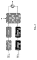
例えば、第1のMUSTタイプ(例えば、MUSTカテゴリ1)においては、同時スケジュールされたWTRUの1つまたは複数のビットは、独立の符号化チェーンを通過させることができる。独立の符号化チェーンは、符号化、レートマッチング、および/またはスクランブリングのうちの1つまたは複数を含むことができる。同時スケジュールされたWTRUの1つまたは複数の符号化ビットは、1つまたは複数の変調シンボルに独立してマッピングすることができる。MUST近WTRUの1つまたは複数の変調シンボルは、 For example, in the first MUST type (eg, MUST category 1), one or more bits of the simultaneously scheduled WTRU can pass through an independent coding chain. An independent coding chain can include one or more of coding, rate matching, and / or scrambling. One or more coded bits of a simultaneously scheduled WTRU can be independently mapped to one or more modulation symbols. One or more modulation symbols of WTRU near MUST

によってスケーリングすることができる。MUST遠WTRUの1つまたは複数の変調シンボルは、 Can be scaled by. One or more modulation symbols of MUST Far WTRU
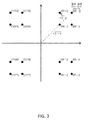
によってスケーリングすることができる。図2は、第1のMUSTタイプのための例示的な送信機ブロック図を示している。図3は、第1のMUSTタイプのための例示的な合成コンステレーションを示している。 Can be scaled by. FIG. 2 shows an exemplary transmitter block diagram for the first MUST type. FIG. 3 shows an exemplary synthetic constellation for the first MUST type.
例えば、第2のMUSTタイプ(例えば、MUSTカテゴリ2)においては、同時スケジュールされたWTRUの1つまたは複数の符号化ビットは、例えば、適応電力比を用いて、成分コンステレーションに合同でマッピングすることができる。MUST近WTRUの1つまたは複数の変調シンボルは、MUST近WTRUおよび/またはMUST遠WTRUの1つまたは複数の符号化ビットに依存することができる。 For example, in a second MUST type (eg, MUST category 2), one or more coded bits of a simultaneously scheduled WTRU are jointly mapped to a component constellation, eg, using adaptive power ratios. be able to. One or more modulation symbols of the MUST near WTRU may depend on one or more coding bits of the MUST near WTRU and / or the MUST far WTRU.
図4は、第2のMUSTタイプのための例示的な送信機ブロック図を示している。図5は、第2のMUSTタイプのための例示的な合成コンステレーションを示している。 FIG. 4 shows an exemplary transmitter block diagram for the second MUST type. FIG. 5 shows an exemplary synthetic constellation for the second MUST type.
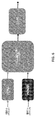
例えば、第3のMUSTタイプ(例えば、カテゴリ3)においては、同時スケジュールされたWTRUの1つまたは複数の符号化ビットは、合成コンステレーションの1つまたは複数のシンボル上において、(例えば、直接的に)重ね合わせることができる。図6は、第3のMUSTタイプのための例示的な送信機ブロック図を示している。 For example, in a third MUST type (eg, category 3), one or more coded bits of the simultaneously scheduled WTRU can be (eg, directly) on one or more symbols of the synthetic constellation. Can be overlaid. FIG. 6 shows an exemplary transmitter block diagram for the third MUST type.
1つまたは複数のラベルビットを、MUST近WTRUまたはMUST遠WTRUに割り当てることができる。図7は、合成コンステレーション上における例示的なラベルビット割り当てを示している。 One or more label bits can be assigned to the MUST near WTRU or the MUST far WTRU. FIG. 7 shows an exemplary label bit assignment on a synthetic constellation.
WTRUは、ネットワークエンティティから通信を受信することができる。通信は、1つまたは複数のタイプの送信および/またはトラフィックを含むことができる。本明細書においては、非限定的な例示目的で、2つのタイプを使用することがあるが、任意の数のタイプを使用することができ、それらは、依然として本明細書における例と整合的であることができる。トラフィックは、1つまたは複数の送信を含むことができる。送信およびトラフィックは、本明細書においては、交換可能に使用することができる。 The WTRU can receive communications from network entities. Communication can include one or more types of transmission and / or traffic. Although two types may be used herein for non-limiting exemplary purposes, any number of types may be used and they are still consistent with the examples herein. There can be. The traffic can include one or more transmissions. Transmission and traffic can be used interchangeably herein.
本明細書において説明される実施形態および例においては、第1のトラフィックタイプは、公称トラフィック(nominal traffic)と呼ばれることがある。第2のトラフィックタイプは、低待ち時間(低遅延時間)トラフィックと呼ばれることがある。第1のトラフィックタイプおよび第2のトラフィックタイプは、異なる待ち時間要件を有することができる。例えば、第2のトラフィックタイプは、第1のトラフィックタイプよりも短い、待ち時間要件を有することができる。第1のトラフィックタイプおよび第2のトラフィックタイプは、トラフィックタイプの非限定的な例として意図されている。1つまたは複数の他の(例えば、他の任意の)トラフィックタイプを使用することができ、それらは、依然として本明細書における例と整合的であることができる。 In the embodiments and examples described herein, the first type of traffic may be referred to as nominal traffic. The second type of traffic is sometimes referred to as low latency (low latency) traffic. The first traffic type and the second traffic type can have different latency requirements. For example, the second traffic type can have a shorter latency requirement than the first traffic type. The first traffic type and the second traffic type are intended as non-limiting examples of traffic types. One or more other (eg, any other) traffic types can be used and they can still be consistent with the examples herein.
第2のトラフィックタイプは、超高信頼性および低待ち時間通信(URLLC)トラフィックを含むことができる。第2のトラフィックタイプ(例えば、低待ち時間トラフィック)は、クリティカルな、高信頼性の、超高信頼性の、またはミッションクリティカルなトラフィックであることができる。例えば、第2のトラフィックタイプは、URLLCタイプのトラフィックであることができる。第1のトラフィックタイプ(例えば、公称トラフィック)は、拡張モバイルブロードバンド(eMBB)タイプのトラフィックを含むことができる。第1のトラフィックタイプは、非クリティカルな、待ち時間制約のより小さい、または待ち時間制約のないタイプのトラフィックであることができる。例えば、第1のトラフィックタイプは、eMBBタイプのトラフィックであることができる。 The second traffic type can include ultra-reliable and low latency communication (URLLC) traffic. The second traffic type (eg, low latency traffic) can be critical, reliable, ultra-reliable, or mission-critical traffic. For example, the second traffic type can be URLLC type traffic. The first traffic type (eg, nominal traffic) can include extended mobile broadband (eMBB) type traffic. The first type of traffic can be a non-critical type of traffic with less latency constraints or no latency constraints. For example, the first traffic type can be eMBB type traffic.
本明細書において説明される実施形態および例においては、URLLCおよび/またはeMBBは、例示的なトラフィックおよび/または送信タイプとして使用されることがある。URLLCおよびeMBBは、非限定的な例として使用され、1つまたは複数の他の(例えば、他の任意の)タイプの送信および/またはトラフィックによって置き換えることができ、依然として本明細書における例と整合的であることができる。 In the embodiments and examples described herein, URLLC and / or eMBB may be used as exemplary traffic and / or transmission types. URLLC and eMBB are used as non-limiting examples and can be replaced by one or more other (eg, any other) type of transmission and / or traffic and are still consistent with the examples herein. Can be targeted.
いくつかのトラフィックは、相対的に重要と見なすことができ、またはさもなければ厳格なQoS要件を有することができる。例えば、低待ち時間(低遅延)トラフィックは、そのようなトラフィックであることができる。(例えば、低待ち時間トラフィックなどの)トラフィックは、予測不可能であることができる。トラフィックは、非周期的および/または低頻度であることができる。例えば、必要とされたときの利用可能性を保証するために、専用リソースを確保しておくことは、スペクトルの非効率的な使用を引き起こすことがあり、および/または望ましくないことがある。そのようなトラフィックのためにリソースを確保しておかないことは、(例えば、低待ち時間トラフィックを送信する必要があることがあるときに)トラフィックのためのリソースの不十分な利用可能性を引き起こすことがある。第1の送信にすでに割り当てられた1つまたは複数のリソースは、第2の送信と共用される、および/または第2の送信に再割り当てされる必要があることがある。 Some traffic can be considered relatively important or can have strict QoS requirements. For example, low latency (low latency) traffic can be such traffic. Traffic (eg, low latency traffic) can be unpredictable. Traffic can be aperiodic and / or infrequent. For example, securing dedicated resources to ensure availability when needed can cause inefficient use of the spectrum and / or may be undesirable. Not reserving resources for such traffic causes inadequate availability of resources for traffic (for example, when low latency traffic may need to be sent). Sometimes. One or more resources already allocated for the first transmission may need to be shared with the second transmission and / or reassigned to the second transmission.
図8は、1つのトラフィックタイプ(例えば、公称トラフィック)から別のトラフィックタイプ(例えば、低待ち時間トラフィック)への例示的なリソース再割り当てを示している。 FIG. 8 shows exemplary resource reallocation from one traffic type (eg, nominal traffic) to another traffic type (eg, low latency traffic).
リソースが、送信間において共用されるとき、または1つの送信が、別の送信に割り当てられた1つまたは複数のリソースを使用するとき、例えば、干渉および/またはパンクチャリングが原因で、性能に影響を与えることがある。同じリソースにおける送信の多重化は、送信に対する性能影響を考慮および/または低減する方式で、可能にすることができる。 Performance impact when resources are shared between transmissions, or when one transmission uses one or more resources assigned to another transmission, for example, due to interference and / or puncture. May be given. Multiplexing of transmissions on the same resource can be enabled in a manner that considers and / or reduces the performance impact on transmissions.
要求、グラント、HARQフィードバック、および/またはデータの送信は、1つもしくは複数のブロックおよび/もしくはチャンクの、例えば、1つもしくは複数のサブフレームのタイミングで、ならびに/またはそれらのタイミングに従って、実行することができる。1つまたは複数のサブフレームの持続時間は、固定された持続時間、および/または知られた持続時間(例えば、1ms)であることができる。持続時間は、送信時間間隔(TTI)と呼ばれることがある。 Requests, grants, HARQ feedback, and / or data transmissions are performed at the timing of one or more blocks and / or chunks, eg, one or more subframes, and / or according to those timings. be able to. The duration of one or more subframes can be a fixed duration and / or a known duration (eg, 1 ms). The duration is sometimes referred to as the transmission time interval (TTI).
リソース要素(RE)は、時間および/または周波数におけるリソースのセットに対応することができる。周波数リソースのセットは、1つまたは複数のサブキャリアのセットを含むことができる。時間リソースのセットは、1つまたは複数の時間サンプルおよび/またはシンボルのセットを含むことができる。LTE REなどのREは、1つのシンボルの時間期間の間に、周波数において1つのサブキャリアを含むことができる。 The resource element (RE) can correspond to a set of resources in time and / or frequency. A set of frequency resources can include a set of one or more subcarriers. A set of time resources can include one or more time samples and / or a set of symbols. A RE, such as LTE RE, may include one subcarrier in frequency during the time period of one symbol.
パンクチャされたRE、および/またはパンクチャされたREのグループは、1つの送信タイプに割り当てる(例えば、初期的に割り当てる)ことができ、2つ以上の送信タイプ(例えば、初期的に割り当てられた送信タイプ、およびパンクチャされた送信タイプ)のためのトラフィックを搬送するために使用することができる。 Punctured REs and / or groups of punctured REs can be assigned to one transmission type (eg, initially assigned) and more than one transmission type (eg, initially assigned transmission). Can be used to carry traffic for types (and punctured transmission types).
待ち時間制約のないトラフィックおよび低待ち時間トラフィックは、REレベルにおいて、多重化することができる。例えば、送信機は、元は第1のタイプのトラフィック(例えば、公称トラフィックnominal traffic)に割り当てられたいくつかのREの1つまたは複数(例えば、すべて)のビットをパンクチャすることができる。送信機は、1つまたは複数(例えば、すべて)のパンクチャされたRE上において、第2のタイプのトラフィック(例えば、低待ち時間トラフィック)を送信して、例えば、低待ち時間トラフィックの送信を可能にすることができる。例えば、送信すべき公称データを有するWTRUと、送信すべき低待ち時間データを有するWTRUが、類似のチャネル状態を経験する場合、送信機は、1つまたは複数の選択されたREのフルパンクチャリングを使用することができる。 Traffic without latency constraints and low latency traffic can be multiplexed at the RE level. For example, the transmitter can puncture one or more (eg, all) bits of several REs originally assigned to the first type of traffic (eg, nominal traffic nominal traffic). The transmitter can send a second type of traffic (eg, low latency traffic) on one or more (eg, all) punctured REs, eg, low latency traffic. Can be. For example, if a WTRU with nominal data to be transmitted and a WTRU with low latency data to be transmitted experience similar channel conditions, the transmitter is fully punctured with one or more selected REs. Can be used.
例えば、送信機は、1つまたは複数のパンクチャされないREに対して、16値直交振幅変調(QAM)を使用することができる。1つまたは複数のパンクチャされないREは、第1のタイプのトラフィック(例えば、公称トラフィック)のために使用することができる。送信機は、1つまたは複数のパンクチャされたREに対して、(例えば、4位相偏移変調(QPSK)変調など)より低次の変調を使用することができる。1つまたは複数のパンクチャされたREは、第2のタイプのトラフィック(例えば、低待ち時間トラフィック)のために使用することができる。図9は、低待ち時間トラフィック904による公称トラフィック902のフルパンクチャリングを用いる例示的なトラフィック多重化を示している。例えば、公称トラフィック902は、16値QAM変調906を有することができ、低待ち時間トラフィック904は、QPSK変調908を有することができる。 For example, the transmitter can use 16-value quadrature amplitude modulation (QAM) for one or more unpunctured REs. One or more unpunctured REs can be used for the first type of traffic (eg, nominal traffic). The transmitter may use lower order modulation for one or more punctured REs (eg, 4-phase shift keying (QPSK) modulation, etc.). One or more punctured REs can be used for a second type of traffic (eg, low latency traffic). FIG. 9 shows exemplary traffic multiplexing with full puncturing of nominal traffic 902 with low latency traffic 904. For example, nominal traffic 902 can have 16-value QAM modulation 906 and low latency traffic 904 can have QPSK modulation 908.
本明細書において説明される実施形態および例においては、16値QAMおよび/またはQPSK変調は、異なる次数の変調の例として使用されることがある。16値QAMおよび/またはQPSK変調は、非限定的な例として使用され、1つまたは複数の他の(例えば、他の任意の)次数の変調によって置き換えることができ、依然として本明細書における例と整合的であることができる。 In the embodiments and examples described herein, 16-value QAM and / or QPSK modulation may be used as examples of modulation of different orders. 16-value QAM and / or QPSK modulation is used as a non-limiting example and can be replaced by one or more other (eg, any other) order modulations, still with the examples herein. Can be consistent.
送信機は、REレベルにおいて、異なるサービスの符号化ビットを多重化して、例えば、同じREまたはREのグループにおいて、公称トラフィックおよび低待ち時間トラフィックの両方を送信することができる。 At the RE level, the transmitter can multiplex the coding bits of different services, eg, transmitting both nominal traffic and low latency traffic in the same RE or group of REs.
例えば、送信されるコンステレーションは、1つまたは複数(例えば、すべて)のサブキャリアおよび/またはシンボルにわたって、一定であり続けることができる。パンクチャされたREのための変調シンボルの1つまたは複数のビットは、公称トラフィックのために使用することができる。変調シンボルの1つまたは複数の残りのビットは、低待ち時間トラフィックのために使用することができる。図10は、階層的変調を使用する例示的なREレベルトラフィック多重化を示している。例えば、コンステレーションは、第1のトラフィック(例えば、公称トラフィック)1002については、16値QAM変調1006であることができ、第2のトラフィック(例えば、低待ち時間トラフィック)1004のために、1つまたは複数(例えば、4つ)のRE上のビットを、パンクチャすることができる。パンクチャされたREの4つのビットのうちの1つまたは複数(例えば、2つ)のビットは、公称トラフィック1002のために使用することができる。パンクチャされたREの1つまたは複数(例えば、2つ)の他のビットは、低待ち時間トラフィックのために使用することができる。別の例においては、コンステレーションは、64値QAM変調を使用することができ、1つまたは複数のパンクチャされたREは、公称トラフィックのために、1つまたは複数(例えば、4つ)のビットを、低待ち時間トラフィックのために、1つまたは複数(例えば、2つ)のビットを使用することができる。別の例においては、コンステレーションは、256値QAM変調を使用することができ、1つまたは複数のパンクチャされたREは、公称トラフィックのために、1つまたは複数(例えば、4つ)のビットを、低待ち時間トラフィックのために、1つまたは複数(例えば、4つ)のビットを使用することができる。公称トラフィックおよび/または低待ち時間トラフィックのビットを区分する1つまたは複数の他の手段を、パンクチャされたリソースにおいて実行することができる。 For example, the constellation transmitted can remain constant across one or more (eg, all) subcarriers and / or symbols. One or more bits of the modulation symbol for the punctured RE can be used for nominal traffic. The remaining bits of one or more of the modulation symbols can be used for low latency traffic. FIG. 10 shows exemplary RE-level traffic multiplexing using hierarchical modulation. For example, the constellation can be 16-value QAM modulation 1006 for the first traffic (eg, nominal traffic) 1002, and one for the second traffic (eg, low latency traffic) 1004. Alternatively, a plurality of (for example, four) bits on the RE can be punctured. One or more (eg, two) bits of the four bits of the punctured RE can be used for nominal traffic 1002. One or more (eg, two) other bits of the punctured RE can be used for low latency traffic. In another example, the constellation can use 64-value QAM modulation, where one or more punctured REs are one or more (eg, four) bits for nominal traffic. , One or more (eg, two) bits can be used for low latency traffic. In another example, the constellation can use 256-value QAM modulation, where one or more punctured REs are one or more (eg, four) bits for nominal traffic. , One or more (eg, 4) bits can be used for low latency traffic. One or more other means of separating the bits of nominal traffic and / or low latency traffic can be performed on the punctured resource.
公称トラフィックの受信機は、1つまたは複数のパンクチャされたREを検出することができる。受信機は、1つまたは複数のパンクチャされたREにおいて、他のトラフィック(例えば、低待ち時間トラフィック)に対して割り当てられたビットロケーション内に、ゼロをパディングして、例えば、復調されたシンボルをデコードすることができる。 The receiver of nominal traffic can detect one or more punctured REs. In one or more punctured REs, the receiver padded zeros within the bit locations assigned to other traffic (eg, low latency traffic), eg, demodulated symbols. It can be decoded.
第2のタイプのトラフィック(例えば、低待ち時間トラフィック)に対して割り当てることができるビットの数を、事前定義しておくこと、(例えば、より高位のレイヤのシグナリングを介して)構成すること、および/または(例えば、ダウンリンク構成情報(DCI)において)示すことができる。ビットマッピング(例えば、グレーマッピング、または非グレーマッピング)を、事前定義しておくこと、(例えば、より高位のレイヤのシグナリングを介して)構成すること、および/または(例えば、DCIにおいて)示すことができる。時間および/または周波数における1つまたは複数の潜在的なパンクチャされるREのロケーションを、事前定義しておくこと、(例えば、より高位のレイヤのシグナリングを介して)構成すること、および/または(例えば、DCIにおいて)示すことができる。 Predefining, configuring (eg, via signaling at higher layers) the number of bits that can be allocated for the second type of traffic (eg, low latency traffic). And / or can be indicated (eg, in the downlink configuration information (DCI)). Bit mapping (eg, gray mapping, or non-gray mapping) must be predefined, configured (eg, via signaling at higher layers), and / or shown (eg, in DCI). Can be done. Predefine, configure (eg, via signaling at higher layers) and / or (eg, through signaling at higher layers) the location of one or more potential punctured REs in time and / or frequency. For example, in DCI).
パンクチャされたデータは、パンクチャされないデータとは異なる変調次数と関連付けることができる。例えば、送信機は、1つまたは複数のパンクチャされたREに対して、第1の変調次数を使用することができる。送信機は、1つまたは複数のパンクチャされないREに対して、第2の変調次数を使用することができる。例においては、第1の変調次数は、第2の変調次数よりも高い変調次数を有することができる。パンクチャされたデータは、異なる変調次数と関連付けられて、例えば、2つの異なるタイプのトラフィック(例えば、公称トラフィックおよび低待ち時間トラフィック)を多重化し、および/または1つまたは複数のパンクチャされたREの復調の信頼性を高めることができる。送信機は、1つまたは複数のパンクチャされたREのための変調次数を、(例えば、公称トラフィックのそれと比較して)低下させることができる。送信機は、1つまたは複数のパンクチャされたREのための変調次数を低下させ、信頼性を高めることができる。公称トラフィックは、低待ち時間トラフィックよりも高い変調次数を有することができる。例えば、変調次数は、(例えば、公称トラフィックのための)16値QAM変調から、(例えば、低待ち時間トラフィックのための)QPSK変調に低下させることができる。 The punctured data can be associated with a different modulation order than the unpunctured data. For example, the transmitter may use the first modulation order for one or more punctured REs. The transmitter may use a second modulation order for one or more unpunctured REs. In the example, the first modulation order can have a higher modulation order than the second modulation order. The punctured data is associated with different modulation orders, eg, multiplexes two different types of traffic (eg, nominal traffic and low latency traffic), and / or one or more punctured REs. The reliability of demodulation can be improved. The transmitter can reduce the modulation order for one or more punctured REs (eg, compared to that of nominal traffic). The transmitter can reduce the modulation order for one or more punctured REs to increase reliability. Nominal traffic can have a higher modulation order than low latency traffic. For example, the modulation order can be reduced from 16-value QAM modulation (eg, for nominal traffic) to QPSK modulation (eg, for low latency traffic).
図11は、パンクチャされたデータに対する異なる変調タイプの例示的な使用を示している。例えば、図11に示されるように、(例えば、公称トラフィックのために使用される)1つまたは複数のパンクチャされないREの変調1102は、16値QAM変調1106であることができ、グレーマッピングを使用することができる。コンステレーションの左および/または右半平面は、公称データシンボルの最上位ビット(MSB)を決定することができる。送信機は、(例えば、低待ち時間トラフィックのために使用される)1つまたは複数のパンクチャされたREに対して、QPSK変調1108を使用することができる。送信機は、(例えば、図11のマッピングに従って)公称データシンボルおよび低待ち時間データシンボルをマッピング(例えば、合同マッピング)することができる。公称データシンボルおよび低待ち時間データシンボルのマッピングは、公称トラフィックの受信機が、元の公称シンボルのMSBを検出する(例えば、高い信頼性で検出する)ことを可能にすることができる。低待ち時間トラフィックの受信機は、送信された低待ち時間シンボルを検出する(例えば、高い信頼性で検出する)ことができる。
FIG. 11 illustrates the exemplary use of different modulation types for punctured data. For example, as shown in FIG. 11, modulation 1102 of one or more unpunctured REs (eg, used for nominal traffic) can be 16-
パンクチャされたREに対して異なる変調次数を使用する1つまたは複数の他の例を、実行することができる。 One or more other examples using different modulation orders for the punctured RE can be performed.
トラフィックは、異なるコンステレーションを使用して、重ね合わせることができる。例えば、1つまたは複数の低待ち時間(低遅延)ビットは、より低い電力レベルにおいて、1つまたは複数の公称ビットとともに送信することができる。1つまたは複数の低待ち時間ビットは、(例えば、複数の直交拡散符号を使用して)時間および/または周波数における複数のポイント上に拡散させることができる。図12Aおよび図12Bは、重なり合う公称トラフィックおよび低待ち時間トラフィックの例を示している。例えば、図12Aに示されるように、1つまたは複数の低待ち時間ビット1204は、それぞれ、BPSK1206およびQPSK1208において変調することができ、それらは、公称トラフィック1202を用いて、(例えば、より低い電力において)同じ時間に送信することができる。公称トラフィック1202の1つまたは複数のビットは、16値QAMを使用して、変調することができる。図12Bに示されるように、1つまたは複数(例えば、2つ)のトラフィックタイプ(例えば、1210、1212)は、重なり合う方式で、送信することができる。例えば、1つまたは複数の低待ち時間ビット(例えば、グレーカラービット)1210は、2つ以上(例えば、8つ)のサブキャリア1214、および/または2つ以上(例えば、2つ)の時間シンボル上に拡散させることができる。1つまたは複数の低待ち時間ビットの電力レベルは、信頼性要件に基づいて、設定および/または制御することができる。例えば、1つまたは複数の低待ち時間ビットの電力レベルは、信頼性要件が高い場合、より高い電力レベルであることができる。拡散符号のサイズ(例えば、拡散係数)は、信頼性要件に基づいて、制御することができる。例えば、信頼性要件が高い場合、より長い拡散符号を使用することができる。受信機において、逆拡散を実行することができる。逆拡散は、1つまたは複数の低待ち時間ビット1210を回復することができる。
Traffic can be overlaid using different constellations. For example, one or more low latency (low latency) bits can be transmitted with one or more nominal bits at lower power levels. One or more low latency bits can be spread over multiple points in time and / or frequency (eg, using multiple orthogonal spread codes). 12A and 12B show examples of overlapping nominal and low latency traffic. For example, as shown in FIG. 12A, one or more
アンテナリソース適応を実行することができる。低待ち時間は、(例えば、初回送信が成功する高い可能性を保証し、繰り返される再送を回避し、および/または過剰な遅延を回避するために)高い送信利得を利用することができる。高い送信利得は、多数のアンテナポートの使用を通して、達成することができる。多数のアンテナポートは、チャネル状態および/またはWTRUロケーションを所与として、より良いプリコーディングおよび/またはビームフォーミングを可能にすることができる。例えば、トラフィックタイプ当たりの与えられた数の送信符号語のために使用されるアンテナポートの数は、調整することができる。アンテナポートの数は、公称トラフィックおよび低待ち時間トラフィックの(例えば、同時)送信に適合するように、調整することができる。 Can perform antenna resource adaptation. Low latency can take advantage of high transmission gain (eg, to ensure a high probability of successful initial transmission, avoid repeated retransmissions, and / or avoid excessive delay). High transmit gain can be achieved through the use of multiple antenna ports. A large number of antenna ports can allow better precoding and / or beamforming given the channel state and / or WTRU location. For example, the number of antenna ports used for a given number of transmit code words per traffic type can be adjusted. The number of antenna ports can be adjusted to accommodate the (eg, simultaneous) transmission of nominal and low latency traffic.
例えば、低待ち時間トラフィックの非存在下において、M>CNominalである場合、次元がM×CNominalである、プリコーディング行列Pを使用することによって、公称トラフィックのCNominal個の符号語の送信のために、M個のアンテナポートおよび/またはレイヤを使用することができる。プリコーディング行列は、ビームフォーミングサブシステムの実際のプリコーダであることができる。プリコーディング行列は、ハイブリッドプリコーディング構造の内部プリコーダであることができる。低待ち時間トラフィックの到着によって、送信機(例えば、eNB)のアンテナリソースマネージャは、1つまたは複数のアンテナリソース(例えば、公称トラフィックのために最初使用されたM個の利用可能なアンテナポートのうちのM1個)を、低待ち時間トラフィックのCLow latency個の符号語の送信用にシフトさせることができる。送信機は、リソース全体のうちのM2=M−M1個のアンテナポートを、公称トラフィックの符号語の送信用に利用する(例えば、それだけを利用する)ことができる。図13は、トラフィックタイプ(例えば、公称トラフィック1302および/または低待ち時間トラフィック1304)に基づいた、例示的なアンテナリソース割り当てを示している。より多くのアンテナポートの低待ち時間トラフィック1304への割り当ては、低待ち時間トラフィック1304についてのロバストな送信(例えば、よりロバストな送信)を可能にすることができる。
For example, in the absence of low latency traffic, if M> C Nominal , then the transmission of C Nominal codes of nominal traffic by using the precoding matrix P of dimension M × C Nominal. For this, M antenna ports and / or layers can be used. The precoding matrix can be the actual precoder of the beamforming subsystem. The precoding matrix can be an internal precoder of a hybrid precoding structure. Due to the arrival of low latency traffic, the antenna resource manager of the transmitter (eg, eNB) will have one or more antenna resources (eg, of the M available antenna ports initially used for nominal traffic). M 1 ) can be shifted for transmission of C Low latency code words for low latency traffic. Transmitter and M 2 = M-M 1 single antenna port of the total resources are available for transmission of the codeword of the nominal traffic can (e.g., it only uses) it. FIG. 13 shows exemplary antenna resource allocation based on traffic type (eg,
例えば、アンテナポートの総数Mが、M>>CNominal1306、M>>CLow latency1308である場合、低待ち時間トラフィック1304のために割り当てられるポートの数は、公称トラフィック1302のビームフォーミング性能に影響を与えることなく、(例えば、独立に)選択することができる。
For example, if the total number of antenna ports M is M >>
1つまたは複数のパンクチャリングパターンを使用することができる。例えば、複数のトラフィックタイプについての情報を多重化するとき、送信機は、例えば、強化された信頼性のために(例えば、チャネル推定誤差に起因する性能悪化を最小化するために)、時間および/または周波数において1つまたは複数の(例えば、任意の)基準シンボルおよび/または固定シンボルに隣接して配置された、1つまたは複数のREをパンクチャすると決定することができる。 One or more puncturing patterns can be used. For example, when multiplexing information about multiple traffic types, the transmitter may use time and, for example, for enhanced reliability (eg, to minimize performance degradation due to channel estimation errors). It can be determined to puncture one or more REs placed adjacent to one or more (eg, any) reference and / or fixed symbols at the / or frequency.
図14は、例えば、強化されたダウンリンク(DL)信頼性のための、例示的なパンクチャリングパターンを示している。例えば、LTEにおいては、図14に示されたTTIのDL送信のために、時間および/または周波数において基準シンボル1402に隣接する1つまたは複数のシンボル(例えば、RE)を、パンクチャリング操作のための可能なロケーションとして、選択することができる。送信機は、事前定義および/または事前構成しておくことができる、パンクチャリングパターンによって決定された時間的に最も早いシンボルから始めて、1つまたは複数のREをパンクチャし始めることができる。例えば、送信機は、低待ち時間トラフィックが発生したとき、および/または低待ち時間トラフィックを送信する必要があるとき、パンクチャリングを開始することができる。パンクチャリングは、事前定義および/または事前構成しておくことができる事前決定された持続時間の間、継続することができる。パンクチャリングは、時間的に示されたシンボルまで、または(例えば、図14に示されるように)TTIの終りまで、継続することができる。 FIG. 14 shows an exemplary puncturing pattern, for example for enhanced downlink (DL) reliability. For example, in LTE, one or more symbols (eg, RE) adjacent to reference symbol 1402 in time and / or frequency for puncturing operation for DL transmission of TTI shown in FIG. Can be selected as a possible location. The transmitter can begin puncturing one or more REs, starting with the earliest symbol in time determined by the puncturing pattern, which can be predefined and / or preconfigured. For example, the transmitter can initiate puncture when low latency traffic occurs and / or needs to be transmitted. Puncturing can continue for a predetermined duration that can be predefined and / or preconfigured. Puncturing can continue until the symbol indicated in time or until the end of the TTI (eg, as shown in FIG. 14).
図15は、強化されたアップリンク(UL)信頼性のための例示的なパンクチャリングパターンを示している。例えば、LTE TTIのアップリンクのために、復調基準信号1504の前および/または後の1つまたは複数のシンボル(例えば、RE)1502を、パンクチャすることができる。多重化されたトラフィックの送信のために、1つまたは複数のシンボルを、パンクチャすることができる。
FIG. 15 shows an exemplary puncturing pattern for enhanced uplink (UL) reliability. For example, one or more symbols (eg, RE) 1502 before and / or after the
図16は、例えば、低減された待ち時間のための、例示的なパンクチャリングパターンを示している。例えば、送信機は、(例えば、複数のトラフィックタイプについての情報を多重化するとき)基準シンボル1602を有する1つまたは複数のサブキャリアを含むことができるパンクチャリングパターンを選択することができる。シンボルは、サブキャリアにマッピングすることができる。サブキャリアは、1つまたは複数のシンボルを搬送するリソースであることができる。サブキャリアは、空白で残すことができ、またはシンボルを詰めることができる。送信機は、例えば、図16における垂直破線の右側において、(例えば、低待ち時間送信のための低減された待ち時間を達成するために)低待ち時間データが到着したときに、パンクチャリングを開始することができる。パンクチャリングは、事前決定された持続時間の間、継続することができる。例においては、パンクチャリングは、時間的に示されたシンボルまで、継続することができる。例においては、パンクチャリングは、TTIの終りまで、継続することができる。 FIG. 16 shows an exemplary puncturing pattern, for example for reduced latency. For example, the transmitter can select a puncture pattern that can include one or more subcarriers with reference symbol 1602 (eg, when multiplexing information about multiple traffic types). Symbols can be mapped to subcarriers. A subcarrier can be a resource that carries one or more symbols. Subcarriers can be left blank or padded with symbols. The transmitter starts puncturing when low latency data arrives, for example, to the right of the vertical dashed line in FIG. 16 (eg, to achieve reduced latency for low latency transmission). can do. Puncturing can continue for a predetermined duration. In the example, puncturing can continue up to the symbol indicated in time. In the example, puncturing can continue until the end of the TTI.
パンクチャされたデータは、制御チャネルを使用して、示すこと、および/または検出することができる。例えば、送信機は、制御チャネルを使用して、1つまたは複数のパンクチャされたREのロケーションをシグナリングすることができる。制御チャネルは、(例えば、多重化されたトラフィックの存在を、公称トラフィックの受信機および/または低待ち時間トラフィックの受信機にシグナリングするために)TTIの終りに配置することができる。図17は、通信における1つまたは複数のパンクチャリングパターンおよび/またはロケーションを示すための例示的な制御信号を示している。例えば、DLについて図17に示されるように、制御情報の長さは、1つのシンボルの持続時間、または複数のシンボルの持続時間であることができる。制御情報は、サブバンドおよび/またはバンド全体にわたって拡散することができる。 Punctured data can be presented and / or detected using control channels. For example, the transmitter can use the control channel to signal the location of one or more punctured REs. The control channel can be located at the end of the TTI (eg, to signal the presence of multiplexed traffic to the receiver of nominal traffic and / or the receiver of low latency traffic). FIG. 17 shows exemplary control signals to indicate one or more puncture patterns and / or locations in communication. For example, as shown in FIG. 17 for DL, the length of the control information can be the duration of one symbol or the duration of multiple symbols. Control information can be spread across subbands and / or bands.
ダウンリンクおよび/またはアップリンクにおいては、制御情報は、パンクチャリング開始の時間インデックス、パンクチャリング停止の時間インデックス、時間および周波数における(例えば、直接的もしくは間接的に)パンクチャされたシンボルの数、またはパンクチャリングパターンのうちの1つまたは複数を含むことができる。 In downlinks and / or uplinks, the control information is the punctured start time index, the punctured stop time index, the number of punctured symbols in time and frequency (eg, directly or indirectly), or. It can include one or more of the puncturing patterns.
図18は、ULにおける1つまたは複数のパンクチャされたロケーションを示すための例示的な制御信号1802を示している。例えば、アップリンクについて図18に示されるように、制御情報は、サウンディング基準信号(SRS)を用いて、エンコードすることができる。SRSの前の1つまたは複数のシンボルは、制御チャネルのために使用することができる。 FIG. 18 shows an exemplary control signal 1802 to indicate one or more punctured locations in UL. For example, as shown in FIG. 18 for the uplink, the control information can be encoded using a sounding reference signal (SRS). One or more symbols before the SRS can be used for the control channel.
1つもしくは複数の直交周波数分割多重(OFDM)シンボル(例えば、各OFDMシンボル)、および/または別の波形シンボルは、制御情報を含むことができる。制御情報は、例えば、現在の、先の、および/または次のパンクチャされるシンボルを示すことができる。制御情報は、パンクチャされるシンボルの1つまたは複数のインデックスを示すことができる。制御情報は、パンクチャされるシンボルの数を示すことができる。制御情報は、パンクチャリングパターンを示すことができる。 One or more orthogonal frequency division multiplexing (OFDM) symbols (eg, each OFDM symbol) and / or another waveform symbol may include control information. The control information can indicate, for example, the current, previous, and / or next punctured symbols. The control information can indicate the index of one or more symbols to be punctured. The control information can indicate the number of symbols to be punctured. The control information can indicate a puncturing pattern.
パンクチャされるデータのインジケーション(例えば、速やかなインジケーション)のために、パンクチャリングインジケータを使用することができる。OFDMシンボル内における1つもしくは複数のサブキャリア、および/または1つもしくは複数のREは、現在および/または隣接OFDMシンボル内に、パンクチャされたサブキャリア(例えば、RE)のセットが存在するかどうかを、(例えば、パンクチャリングインジケータを介して)示すことができる。パンクチャリングインジケータは、例えば、待ち時間低減のために、使用することができる。図19は、シンボル内におけるパンクチャされたロケーションの例示的なインジケーションを示している。例えば、図19に示されるように、パンクチャリングインジケータ1902のロケーションは、固定されること、および/または事前定義しておくことができる。パンクチャリングパターンのロケーションは、事前定義しておくこと、および/またはシグナリング(例えば、より高位のレイヤのシグナリング)を介して、半静的に伝達することができる。1つまたは複数のパンクチャされたREの存在は、パンクチャリングインジケータのOFDMシンボル内において示すことができる。例えば、同じOFDMシンボル内におけるREの1つは、1つまたは複数のパンクチャされたREを示すことができる。例えば、同じOFDMシンボル内におけるREの1つは、1つまたは複数のパンクチャされたREを示すように、例えば、2値インジケータの1もしくは−1に設定することができる(または1もしくは0に設定することができる)。同じOFDMシンボル内におけるREの1つは、1つまたは複数のパンクチャされたREの存在を示すように1に設定することができる。同じOFDMシンボル内におけるREの1つは、1つまたは複数のパンクチャされたREの非存在を示すように−1(または0)に設定することができる。変調タイプは、1つまたは複数のパンクチャされたREを示すように変更することができる。
A punctured indicator can be used for the indication of punctured data (eg, rapid indication). Whether one or more subcarriers in an OFDM symbol and / or one or more REs have a set of punctured subcarriers (eg, REs) in the current and / or adjacent OFDM symbols. Can be indicated (eg, via a puncturing indicator). The puncturing indicator can be used, for example, to reduce latency. FIG. 19 shows an exemplary indication of a punctured location within a symbol. For example, as shown in FIG. 19, the location of the
図20は、パンクチャリングインジケータリソース内において、パンクチャリングインジケータおよび公称データを多重化する例を示している。例えば、REのセットは、データおよび制御情報の両方を(例えば、同時に)搬送することができる。1つまたは複数の制御ビットおよび1つまたは複数のデータビットは、コンステレーションポイント(例えば、同じコンステレーションポイント)において多重化することができる。送信すべき公称データおよび/または低待ち時間(低遅延)データを有する1つまたは複数のWTRUは、REのセットを監視(モニター)することができる。WTRUは、REのセットを監視して、隣接パンクチャリングパターンにおけるREがパンクチャされるかどうかを決定することができる。例えば、図20に示されるように、パンクチャリングインジケータREは、16値QAMを使用することができる。パンクチャリングインジケータREの最上位ビットは、パンクチャリングを示すことができる。例えば、パンクチャリングインジケータREの最上位ビットは、パンクチャリングを示すために、1であることができる。パンクチャリングインジケータREの最上位ビットは、非パンクチャリングを示すために、0であることができる。パンクチャリングインジケータREの最後の3ビットは、公称WTRUについてのデータ転送のために使用することができる。 FIG. 20 shows an example of multiplexing the puncture indicator and the nominal data within the puncture indicator resource. For example, a set of REs can carry both data and control information (eg, simultaneously). One or more control bits and one or more data bits can be multiplexed at a constellation point (eg, the same constellation point). One or more WTRUs with nominal data to be transmitted and / or low latency (low latency) data can monitor a set of REs. The WTRU can monitor the set of REs to determine if the REs in the adjacent puncturing pattern are punctured. For example, as shown in FIG. 20, the puncturing indicator RE can use 16-value QAM. The most significant bit of the puncture indicator RE can indicate puncture. For example, the most significant bit of the puncture indicator RE can be 1 to indicate puncture. The most significant bit of the puncture indicator RE can be 0 to indicate non-puncture. The last 3 bits of the puncture indicator RE can be used for data transfer for the nominal WTRU.
1つまたは複数のリソースは、例えば、動的に、借用することができる。1つまたは複数のリソースを動的に借用することは、(例えば、待ち時間制約のない送信に対する影響を低減するなど)待ち時間制約のない送信の性能測定に影響を与えることができる。第1のタイプのトラフィックのダウンリンク送信のために割り当てられたリソースのいくらかが使用されて、第2のタイプのトラフィックを送信することができる。第1のタイプのトラフィックの例は、モバイルブロードバンドトラフィックであることができる。第2のタイプのトラフィックの例は、低待ち時間データであることができる。このケースにおいては、第1のタイプのトラフィックの送信の性能は、悪化することがある。性能は、ブロック誤り率など、様々なパラメータを使用することによって測定することができる。 One or more resources can be borrowed dynamically, for example. Dynamically borrowing one or more resources can affect performance measurements of latency-constrained transmissions (eg, reducing the impact on latency-constrained transmissions). Some of the resources allocated for downlink transmission of the first type of traffic can be used to transmit the second type of traffic. An example of the first type of traffic can be mobile broadband traffic. An example of the second type of traffic can be low latency data. In this case, the performance of transmitting the first type of traffic may be degraded. Performance can be measured by using various parameters such as block error rate.
例えば、性能悪化は、1つまたは複数のリソース(例えば、追加リソース)を第1のタイプのトラフィックのダウンリンク送信に割り当てることによって、低減および/または防止することができる。1つまたは複数のリソース(例えば、追加リソース)は、第2のタイプのトラフィックが、第1のタイプのトラフィックからのリソースを使用しなかった場合には、第1のタイプのトラフィックのアップリンク送信のために割り当てられていたシンボルを含むことができる。 For example, performance degradation can be reduced and / or prevented by allocating one or more resources (eg, additional resources) to the downlink transmission of the first type of traffic. One or more resources (eg, additional resources) will uplink transmission of the first type of traffic if the second type of traffic does not use resources from the first type of traffic. Can include symbols that have been assigned for.
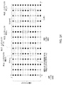
DLデータは、1、2、...、Nなどの、データ部分を含むことができ、各部分は、1つのOFDMシンボル上において送信されるように、スケジュールしてあることができる。例えば、OFDMシンボル1は、データ部分1を搬送することができ、OFDMシンボル2は、データ部分2を搬送することができるなどである。図21は、TDD TTI内における例示的な動的リソース借用を示している。図21に示されるように、TTIのDL部分は、1つまたは複数(例えば、6つ)のOFDMシンボルを含むことができる。1つまたは複数のOFDMシンボルの各々は、例えば、第1のタイプのトラフィックからのデータの一部を搬送することができる。1つまたは複数のOFDMシンボルのうちのOFDMシンボル(例えば、OFDMインデックスk=3)を、パンクチャすることができる。パンクチャされたOFDMシンボルは、第1のタイプのトラフィックの送信のために利用可能でないことができる。
DL data is 1, 2, ... .. .. Data parts such as, N, etc. can be included, and each part can be scheduled to be transmitted on one OFDM symbol. For example, the
例えば、パンクチャされたシンボルに後続する第1のDLシンボル(例えば、シンボルインデックスk+1)は、データ部分kを搬送することができる。図21に示されるように、シンボル3をパンクチャすることができる。パンクチャされたシンボルに後続する次のDLシンボル(例えば、シンボル4)は、データ部分3を搬送することができる。最初にDL送信のために割り当てられたDLシンボルの数は、データ部分の数よりも少ないことがある。最初はアップリンク送信のために予約されたものから、1つまたは複数のシンボルを借用することができる。1つまたは複数の借用されたシンボルは、ダウンリンク送信のために使用することができる。図21に示されるように、例えば、例1は、インデックス1を有するULシンボルのために割り当てられた時間を含むことができる。インデックス1を有するULシンボルのために割り当てられた時間を使用して、データ部分5を搬送するダウンリンクシンボルを送信することができる。
For example, the first DL symbol following the punctured symbol (eg, symbol index k + 1) can carry the data portion k. As shown in FIG. 21,
図21に示されるように、例2においては、1つまたは複数のDLシンボルは、元はDLシンボルに割り当てられたデータ部分を搬送することができる。パンクチャされたDLシンボルによって搬送されることになっていたデータ部分は、TTIのUL領域内において送信されるDLシンボルによって搬送することができる。 As shown in FIG. 21, in Example 2, the one or more DL symbols can carry the data portion originally assigned to the DL symbol. The data portion that was to be carried by the punctured DL symbol can be carried by the DL symbol transmitted within the UL region of the TTI.
ULシンボルのうちの1つまたは複数が、DL送信に割り当てられるとき、アップリンク送信は、(例えば、より高い符号化率を引き起こす)より少ないリソースが原因で、厄介になることがある。ブロック誤り率の低下は、dBの分数またはより大きいことができる。ブロック誤り率の低下は、例えば、DL送信によって借用されたULリソースの量に基づくことができる。WTRUは、(例えば、符号化率の低下を補償するために)例えば、より高い電力を用いて、ULシンボルを送信するように構成することができる。 When one or more of the UL symbols are assigned to DL transmissions, uplink transmissions can be awkward due to less resources (eg, causing higher code rates). The reduction in block error rate can be a fraction of dB or greater. The reduction in block error rate can be based, for example, on the amount of UL resources borrowed by DL transmission. The WTRU can be configured to transmit UL symbols, for example, with higher power (eg, to compensate for the reduced code rate).
制御チャネル(例えば、既存の制御チャネル、または新しい制御チャネル)を定義すること、変更することなどができる。制御チャネルは、ULリソースのいくらかがDLのために使用されたことを、1つまたは複数のWTRUに(例えば、インジケータを介して)通知することができる。制御チャネルは、新しい電力設定を、1つまたは複数のWTRUに示すことができる。制御チャネルは、(例えば、本明細書において説明されるように)事前定義されたロケーションに配置することができる。例えば、制御チャネルは、元のDL送信の最後のOFDMシンボルに配置することができる。制御チャネルが、例えば、元のDL送信の最後のOFDMシンボルに配置されるとき、1つまたは複数のWTRUは、(例えば、最後のDL OFDMシンボルにおいて)制御チャネルを読み取ることができる。制御チャネルが、DL送信のパンクチャリングに関する情報を含む場合、1つまたは複数のWTRUは、UL OFDMシンボルのうちの1つまたは複数において、送信しないことができる。1つまたは複数のUL OFDMシンボルの間、1つまたは複数のWTRUは、DLトラフィックの受信を継続することができる。 Control channels (eg, existing control channels or new control channels) can be defined, modified, and so on. The control channel can notify one or more WTRUs (eg, via an indicator) that some of the UL resources have been used for the DL. The control channel can indicate the new power setting to one or more WTRUs. The control channel can be located at a predefined location (eg, as described herein). For example, the control channel can be placed at the last OFDM symbol of the original DL transmission. When the control channel is placed, for example, in the last OFDM symbol of the original DL transmission, one or more WTRUs can read the control channel (eg, in the last DL OFDM symbol). If the control channel contains information about puncturing DL transmissions, one or more WTRUs may not transmit at one or more of the UL OFDM symbols. Between one or more UL OFDM symbols, one or more WTRUs can continue to receive DL traffic.
制御チャネルが、元のDL送信の最後のOFDMシンボルに配置されるとき、制御チャネル内においてシグナリングされる情報は、DL送信のために割り当てられたULシンボルの数、および/またはUL送信のための電力増加などのうちの1つまたは複数を含むことができる。 When the control channel is placed in the last OFDM symbol of the original DL transmission, the information signaled within the control channel is the number of UL symbols assigned for the DL transmission and / or for the UL transmission. It can include one or more of power increases and the like.
制御チャネルが、元のDL送信の最後のOFDMシンボルに配置され、UL送信が、開始したとき、1つまたは複数のWTRUは、制御チャネル内において示された送信電力を使用することができる。 When the control channel is placed in the last OFDM symbol of the original DL transmission and UL transmission is initiated, one or more WTRUs can use the transmitted power indicated within the control channel.
1つまたは複数のリソースは、自己完結的なTDDサブフレーム内において、DLシンボルおよびULシンボルの間で共用することができる。時間窓(例えば、TTI)内において、Nsym個のシンボルを配置し、使用し、および/または構成することができる。Nsym個のシンボルのうちの第1のサブセットは、ダウンリンク送信のために使用することができる。Nsym個のシンボルのうちの第2のサブセットは、アップリンク送信のために使用することができる。ダウンリンク送信のために使用されるNsym個のシンボルのうちの第1のサブセットは、DLシンボルと呼ばれることがある。アップリンク送信のために使用されるNsym個のシンボルのうちの第2のサブセットは、ULシンボルと呼ばれることがある。 One or more resources can be shared between DL and UL symbols within a self-contained TDD subframe. Within the time window (eg, TTI), Nsym symbols can be placed, used, and / or configured. The first subset of the Nsym symbols can be used for downlink transmission. A second subset of the Nsym symbols can be used for uplink transmission. The first subset of the Nsym symbols used for downlink transmission is sometimes referred to as the DL symbol. A second subset of the Nsym symbols used for uplink transmission may be referred to as UL symbols.
時間窓内におけるDLシンボルおよびULシンボルは、時間領域において重なり合わないことができる。 The DL and UL symbols in the time window can not overlap in the time domain.
DLシンボルは、最初のNDL個のシンボルに配置することができる。ULシンボルは、最後のNUL個のシンボルに配置することができる。 DL symbols can be placed on the first N DL symbols. UL symbols can be placed on the last N UL symbols.
DLシンボルまたはULシンボルの部分ではないシンボルは、ガードシンボルと呼ばれることがある。ガードシンボル、ギャップ、切り換え時間、切り換えシンボル、およびDL−UL切り換え時間は、本明細書においては交換可能に使用することができる。 Symbols that are not part of the DL or UL symbols are sometimes referred to as guard symbols. The guard symbol, gap, switching time, switching symbol, and DL-UL switching time can be used interchangeably herein.
NDLおよび/またはNULは、時間窓内におけるガードシンボルのロケーションに基づいて、決定することができる。時間窓内において、1つまたは複数のガードシンボルを使用することができる。1つまたは複数のガードシンボルは、DLシンボルまたはULシンボルの間に配置することができる。ガードシンボルの数、および/または時間窓内におけるガードシンボルのロケーションは、事前定義しておくこと、(例えば、より高位のレイヤのシグナリングを介して)構成すること、および/または1つもしくは複数のDLシンボル内(の、例えば、DCI)において示すことができる。 The N DL and / or N UL can be determined based on the location of the guard symbol within the time window. Within the time window, one or more guard symbols can be used. One or more guard symbols can be placed between DL symbols or UL symbols. The number of guard symbols and / or the location of guard symbols within the time window should be predefined, configured (eg, via signaling at higher layers), and / or one or more. It can be shown in (for example, DCI) in the DL symbol.
第1のタイプのトラフィック(例えば、通常待ち時間トラフィック)のためのダウンリンク送信のために、NDL個のDLシンボルを使用することができる。第2のタイプのトラフィック(例えば、低待ち時間トラフィック)のためのダウンリンク送信のために、NDL個のDLシンボルのうちの1つまたは複数を使用することができる。以下のうちの1つまたは複数を適用することができる。 N DL DL symbols can be used for downlink transmission for the first type of traffic (eg, normal latency traffic). The second type of traffic (e.g., low latency traffic) can be used for downlink transmissions for one of the N DL number of DL symbols or multiple. One or more of the following can be applied.
第1のタイプのトラフィックは、ダウンリンクデータおよび/または関連付けられたダウンリンク制御チャネルのために、NDL個のDLシンボルを使用することができる。DLデータが送信されているとき、関連付けられたダウンリンク制御チャネルを使用して、そのDLデータに関する1つまたは複数の制御情報(例えば、データがどこに配置されるか、どの変調タイプが使用されるか)を送信することができる。第2のタイプのトラフィックは、ダウンリンクデータおよび/または関連付けられたダウンリンク制御チャネルのために、NDL個のDLシンボルのサブセットを使用することができる。第1のタイプのトラフィックのためのダウンリンク送信は、第2のタイプのトラフィックのためのダウンリンク送信によって、パンクチャ、レートマッチング、および/またはヌル化することができる。1つまたは複数のパンクチャ、レートマッチング、および/またはヌル化されたDLシンボルを、WTRUに示すことができる。パンクチャ、レートマッチング、および/またはヌル化されたDLシンボルの数を、1つまたは複数のDLシンボル(例えば、第NDLのシンボル)内において示すことができる。 The first type of traffic, for downlink data and / or associated downlink control channel, may be used N DL number of DL symbols. When the DL data is being transmitted, the associated downlink control channel is used to use one or more control information about the DL data (eg, where the data is located, which modulation type is used). Can be sent. The second type of traffic, for downlink data and / or associated downlink control channel, it is possible to use a subset of the N DL number of DL symbols. Downlink transmissions for the first type of traffic can be punctured, rate matched, and / or nullified by downlink transmissions for the second type of traffic. One or more punctures, rate matching, and / or nullified DL symbols can be shown to the WTRU. The number of punctured, rate matching, and / or nullified DL symbols can be indicated within one or more DL symbols (eg, the symbol of the N DL ).
1つまたは複数のガードシンボルのロケーションは、(例えば、第2のタイプのトラフィックのために使用されるDLシンボルの数に基づいて)変更することができる。例えば、1つのDLシンボルが、第2のタイプのトラフィックのために使用され、第1のタイプのトラフィックについてパンクチャ、レートマッチング、および/またはヌル化される場合、ガードシンボルの時間ロケーションは、第2のタイプのトラフィックのために使用されるDLシンボルの数(例えば、1つのDLシンボル)だけ遅らせることができる。ULシンボルの数は、第2のタイプのトラフィックのために使用されるDLシンボルの数に基づいて、減少させることができる。ULシンボルの数は、ガードシンボルの時間ロケーションのために遅らされたシンボルの数に基づいて、減少させることができる。DLシンボルの数は、第2のタイプのトラフィックのために使用されるシンボルの数に基づいて、増加させることができる。例えば、時間窓内において、第2のタイプのトラフィックのために、NSE個のシンボルが使用される場合、時間窓内におけるDLシンボルの数は、NDL+NSEに変更することができる。 The location of one or more guard symbols can be changed (eg, based on the number of DL symbols used for the second type of traffic). For example, if one DL symbol is used for a second type of traffic and is punctured, rate matched, and / or nulled for the first type of traffic, the time location of the guard symbol is the second. It can be delayed by the number of DL symbols used for this type of traffic (eg, one DL symbol). The number of UL symbols can be reduced based on the number of DL symbols used for the second type of traffic. The number of UL symbols can be reduced based on the number of symbols delayed due to the time location of the guard symbol. The number of DL symbols can be increased based on the number of symbols used for the second type of traffic. For example, if N SE symbols are used for the second type of traffic in the time window, the number of DL symbols in the time window can be changed to N DL + N SE .
第2のタイプのトラフィックのために使用することができるDLシンボルの数は、ある数、例えば、Nmaxまでに制限することができる。例えば、Nmaxは、NDL−NCL以下であることができる。NCLは、ダウンリンク制御チャネルのために使用されるDLシンボルの数と呼ばれることがある。NCLは、「0」を含むことができる。NCLは、事前定義された数であること、より高位のレイヤのシグナリングを介して構成すること、および/または各時間窓内において動的に示すことができる。NCLは、NDL、NUL、および/または時間窓内におけるシンボルの数のうちの少なくとも1つに基づいて、決定することができる。 The number of DL symbols that can be used for the second type of traffic can be limited to a certain number, eg Nmax. For example, Nmax may be equal to or less than N DL -N CL. The NC L is sometimes referred to as the number of DL symbols used for the downlink control channel. NC L can include "0". NC Ls can be predefined numbers, configured via signaling in higher layers, and / or dynamically indicated within each time window. The NC L can be determined based on at least one of the number of symbols in the N DL , N UL , and / or time window.
ギャップのために使用されるシンボルの数は、第2のタイプのトラフィックのために使用されるシンボルの数に基づいて、変更することができる。例えば、ガードシンボルのために、NGAP個のシンボルを決定することができる。時間窓内における第2のタイプのトラフィックのために、NSE個のシンボルを使用することができる。ギャップのために使用されるシンボルの数は、NGAP個のシンボルからNGAP−NSE個のシンボルに減少させることができる。NGAPおよび/またはNSEを、WTRUは、知ることができる。NGAPは、(例えば、より高位のレイヤのシグナリングを介して)構成すること、および/または示すこと(例えば、動的に示すこと)ができる。NSEは、時間窓内における1つまたは複数のDLシンボル(例えば、NDL個のDLシンボルにおける知られたロケーション)において示すことができる。(例えば、NSE個のシンボルが第2のタイプのトラフィックのために使用される時間窓内において、アップリンク送信のためにスケジュールすることができる)WTRUは、NGAPおよび/またはNSEに基づいて、アップリンク送信を決定することができる。NGAP−NSEが、事前決定された閾値よりも小さい場合、WTRUは、時間窓内におけるアップリンク送信をやめることができる。例えば、NGAP−NSEが、WTRUのタイミング進み値よりも小さい場合、WTRUは、スケジュールされたアップリンク送信をやめることができる。NGAP−NSEが、事前決定された閾値よりも小さい場合、WTRUは、1つまたは複数のULシンボルのうちの最初のシンボルを、ガードシンボルとして使用することができる。 The number of symbols used for the gap can be changed based on the number of symbols used for the second type of traffic. For example, for guard symbols, N GAP symbols can be determined. N SE symbols can be used for the second type of traffic within the time window. The number of symbols used for the gap can be reduced from N GAP symbols to N GAP -N SE symbols. WTRU can know N GAP and / or N SE . N GAPs can be configured (eg, via signaling in higher layers) and / or indicated (eg, dynamically indicated). The N SE can be indicated by one or more DL symbols within the time window (eg, known locations in N DL DL symbols). WTRU is based on N GAP and / or N SE (for example, within the time window where N SE symbols are used for the second type of traffic, can be scheduled for uplink transmission). The uplink transmission can be decided. If the N GAP- N SE is less than the predetermined threshold, the WTRU can stop the uplink transmission within the time window. For example, if N GAP- N SE is less than the timing advance value of WTRU, WTRU can stop the scheduled uplink transmission. If N GAP- N SE is less than a predetermined threshold, WTRU may use the first symbol of one or more UL symbols as a guard symbol.
TTIの1つまたは複数のタイミング境界を、変更することができる。TTIの1つまたは複数のタイミング境界は、(例えば、TTI内における1つまたは複数のパンクチャされたシンボルを補償するために)境界をそれ以降の時間瞬間またはそれ以前の時間瞬間に動かすことによって、変更することができる。例えば、TTI内において、m個のシンボルがパンクチャされた場合、TTIは、mT秒だけ拡張することができ、ここで、mは、パンクチャされたシンボル(例えば、OFDMシンボル)の数であり、Tは、シンボル持続時間である。1つまたは複数の変更されるタイミング境界を有するTTIは、融通性があるTTIと呼ばれることがある。 One or more timing boundaries of the TTI can be modified. One or more timing boundaries of a TTI can be made by moving the boundary (for example, to compensate for one or more punctured symbols within the TTI) to a later time moment or an earlier time moment. Can be changed. For example, in TTI, if m symbols are punctured, TTI can be expanded by mT seconds, where m is the number of punctured symbols (eg, OFDM symbols) and T. Is the symbol duration. A TTI with one or more modified timing boundaries is sometimes referred to as a flexible TTI.
図22は、例示的な融通性があるTTIを示している。例えば、第1のTTI(例えば、TTI m)2202は、時間t=t0からt=t1内において送信されるように、スケジュールしておくことができる。第1のTTI2202の持続時間は、固定することができる。第1のTTI2202の持続時間は、例えば、10Tに等しいことができる。第1のTTI内のシンボルの1つがパンクチャされ、1つのシンボルが持続時間Tを有するとき、TTIの終了ポイントは、t=t1+Tまで拡張することができる。第1のタイプのトラフィックの送信は、シンボルがパンクチャされた時間の間、停止することができる。第1のタイプのトラフィックの送信は、例えば、パンクチャリングが終了した後、再開することができる。第1のTTIの持続時間は、例えば、10Tから10+1=11Tまで増加することができる。 FIG. 22 shows an exemplary flexible TTI. For example, the first TTI (eg, TTI m) 2202 can be scheduled to be transmitted within time t = t0 to t = t1. The duration of the first TTI2202 can be fixed. The duration of the first TTI2202 can be, for example, equal to 10T. When one of the symbols in the first TTI is punctured and one symbol has a duration T, the end point of the TTI can be extended to t = t1 + T. The transmission of the first type of traffic can be stopped during the time the symbol is punctured. Transmission of the first type of traffic can be resumed, for example, after puncturing is complete. The duration of the first TTI can be increased, for example, from 10T to 10 + 1 = 11T.
TTIのタイミングが拡張されたとき、以降のTTIのいくつかは、例えば、TTI(またはサブフレーム)のグループのタイミングを維持するために短縮されることがある。例えば、図22に示されるように、第2のTTI(例えば、TTI m+1)2204は、(例えば、第1および第2のTTIの合計持続時間が保存されるように)第1のTTIが拡張された量(例えば、同じ量)だけ、短縮することができる。 When the timing of a TTI is extended, some of the subsequent TTIs may be shortened, for example, to maintain the timing of a group of TTIs (or subframes). For example, as shown in FIG. 22, the second TTI (eg, TTI m + 1) 2204 has an extended first TTI (eg, such that the total duration of the first and second TTIs is preserved). It can be shortened by the amount (eg, the same amount).
制御チャネル(例えば、既存の制御チャネル、または新しい制御チャネル)を定義すること、変更することなどができる。例えば、制御チャネルは、TTI境界が拡張されたことを、1つまたは複数のWTRUに示すことができる。制御チャネルは、事前定義されたロケーション内に存在することができる。例えば、制御チャネルは、第1のTTIの最後のOFDMシンボルに存在することができる。 Control channels (eg, existing control channels or new control channels) can be defined, modified, and so on. For example, the control channel can indicate to one or more WTRUs that the TTI boundary has been extended. The control channel can be in a predefined location. For example, the control channel can be present at the last OFDM symbol of the first TTI.
送信機は、(例えば、他のトラフィックからのパンクチャリングに対する公称送信の増強されたロバスト性のために)パンクチャされたTTIの後(例えば、直後)のTTIの間、2符号語送信のための公称トラフィックを構成することができる。以下のうちの1つまたは複数を適用することができる。 The transmitter is for two-code transmission during the TTI after the punctured TTI (eg, immediately after) (eg, due to the enhanced robustness of the nominal transmission against puncturing from other traffic). Nominal traffic can be configured. One or more of the following can be applied.
TTI #n+1内において、送信機は、TTI #n(例えば、パンクチャされたRE)内においてパンクチャされた公称データを再送する(例えば、それだけを再送する)ことができる。TTI #n+1内において、送信機は、時分割方式で送信される2つの符号語のために、構成することができる。第1の符号語は、TTI #n内においてパンクチャされた公称データを搬送することができる。第2の符号語は、例えば、TTI #n+1内における公称トラフィックについてのデータ(例えば、新しいデータ)を搬送することができる。TTI #nのパンクチャされたREの再送を搬送する符号語は、パンクチャリングパターンの外部の1つまたは複数のREに(例えば、他の多重化トラフィックによってパンクチャされないことができるリソースに)マッピングすることができる。 Within TTI # n + 1, the transmitter can retransmit (eg, only retransmit) the punctured nominal data within TTI # n (eg, punctured RE). Within TTI # n + 1, the transmitter can be configured for two code words transmitted in a time division manner. The first code word can carry the punctured nominal data within TTI # n. The second code term can carry data (eg, new data) about nominal traffic within TTI # n + 1, for example. The code word carrying the retransmission of the punctured RE of TTI # n should be mapped to one or more REs outside the puncturing pattern (eg, to a resource that cannot be punctured by other multiplexed traffic). Can be done.
公称(例えば、eMBB)DL再送は、パンクチャされたデータを送信する(例えば、それだけを送信する)ことができる。公称DL再送は、同じTTI内において時分割多重化される第2の符号語を使用することができる。パンクチャされたTTIの後(例えば、直後)のTTIは、第1の符号語を使用して、パンクチャされたシンボルを再送することができる。OFDMシンボルのサブセット(例えば、サブセットだけ)を、低待ち時間トラフィックによってパンクチャすることができる。サブセットは、事前定義しておくこと、および/または構成することができる。次のTTI内における、符号語(例えば、2つの符号語のうちの一方)を使用した、パンクチャされたデータの再送時には、再送は、1つまたは複数のパンクチャ不可のリソースにマッピングすることができる。 Nominal (eg, eMBB) DL retransmissions can transmit punctured data (eg, only that). Nominal DL retransmissions can use a second code word that is time-division-multiplexed within the same TTI. The TTI after (eg, immediately after) the punctured TTI can use the first code word to retransmit the punctured symbol. A subset of OFDM symbols (eg, only a subset) can be punctured by low latency traffic. Subsets can be predefined and / or constructed. When resending punctured data using a code word (eg, one of two code words) in the next TTI, the retransmission can be mapped to one or more non-punctured resources. ..
符号ブロック当たりの巡回冗長検査(CRC)を用いる複数の符号ブロックは、元のトランスポートブロックサイズ(TBS)内において使用することができる(例えば、そのため、公称トラフィックの再送は、影響された符号ブロックだけを送信する)。 Multiple code blocks with Cyclic Redundancy Check (CRC) per code block can be used within the original transport block size (TBS) (eg, so the retransmission of nominal traffic is affected code blocks. Only send).
チャネル帯域幅は、2つ以上の区画に分割することができる。2つ以上の区画の各々は、特定のタイプのトラフィック(例えば、プライマリトラフィック)の送信のために、使用する(例えば、主に使用する)ことができる。例えば、第1のチャネルは、2つの区画に分割することができる。第1の区画は、eMBBトラフィックのために予約することができる。第2の区画は、URLLCトラフィックのために予約することができる。eMBBトラフィックは、第1の区画についてのプライマリトラフィックであることができる。URLLCトラフィックは、第2の区画についてのプライマリトラフィックであることができる。 The channel bandwidth can be divided into two or more compartments. Each of the two or more compartments can be used (eg, primarily used) for the transmission of a particular type of traffic (eg, primary traffic). For example, the first channel can be divided into two compartments. The first parcel can be reserved for eMBB traffic. The second compartment can be reserved for URLLC traffic. The eMBB traffic can be the primary traffic for the first partition. The URLLC traffic can be the primary traffic for the second partition.
2つの区画のうちの一方におけるトラフィック負荷が、閾値を下回るとき、その区画は、セカンダリトラフィックの送信のために使用することができる。セカンダリトラフィックは、区画に割り当てられたプライマリトラフィック以外のタイプのトラフィックを含むことができる。例えば、URLLCトラフィックのために予約された第2の区画は、(例えば、URLLCトラフィックが散発的であるとき)eMBBトラフィックのために使用することができる。eMBBは、第2の区画上におけるセカンダリトラフィックであることができ、URLLCトラフィックは、プライマリトラフィックであることができる。 When the traffic load on one of the two partitions is below the threshold, that partition can be used for the transmission of secondary traffic. Secondary traffic can include types of traffic other than the primary traffic assigned to the partition. For example, a second partition reserved for URLLC traffic can be used for eMBB traffic (eg, when URLLC traffic is sporadic). The eMBB can be secondary traffic on the second partition and the URLLC traffic can be primary traffic.
セカンダリトラフィックに属するデータは、(例えば、プライマリトラフィックとは別個に)エンコードすることができる。例えば、eMBBデータは、2つの符号語にエンコードすることができる。第1の符号語は、第1の区画内において送信することができ、第2の符号語は、第2の区画内において送信することができる。セカンダリトラフィックは、(例えば、URLLCデータが到着し、この区画内において送信しなければならないとき)その区画と関連付けられたプライマリトラフィックからのパンクチャリングを経験することがある。送信機は、(例えば、セカンダリ区画のプライマリトラフィックからのパンクチャリングをこうむることがあるセカンダリトラフィックの信頼性を改善するために)セカンダリ区画にマッピングされる符号語に対して、変調(例えば、より低次の変調)および/または符号化方式を使用することができる。例えば、送信すべきeMBBデータを有するWTRUは、2つの符号語を、すなわち、第1の区画内の第1の符号語、および第2の区画内の第2の符号語を受け取ることができる。第2の区画内の第2の符号語は、低次のMCSを用いて送信することができる。(例えば、チャネルの品質が原因で)低次の変調および符号化方式(MCS)送信を必要とすることがある1つまたは複数のWTRUのために、セカンダリトラフィックをスケジュールすることができる。 Data belonging to secondary traffic can be encoded (eg, separately from primary traffic). For example, eMBB data can be encoded into two code words. The first code word can be transmitted within the first compartment and the second code word can be transmitted within the second compartment. Secondary traffic may experience puncture from the primary traffic associated with that parcel (eg, when URLLC data arrives and must be transmitted within this parcel). The transmitter modulates (eg, lower) the code words that are mapped to the secondary partition (eg, to improve the reliability of secondary traffic that may suffer punctures from the primary traffic in the secondary partition) The following modulation) and / or coding schemes can be used. For example, a WTRU with eMBB data to be transmitted can receive two code words, i.e. the first code word in the first compartment and the second code word in the second compartment. The second code word in the second compartment can be transmitted using a lower order MCS. Secondary traffic can be scheduled for one or more WTRUs that may require low-order modulation and coding scheme (MCS) transmission (eg, due to channel quality).
図23は、例示的な電力上昇を示している。例えば、送信機は、パンクチャリングの後に送信される1つまたは複数のリソースのための送信電力を増加させることができる。送信機は、送信電力を増加させて、例えば、パンクチャリングに起因する性能低下を防止または緩和することができる。図23に示されるように、公称トラフィックのために、N個のサブキャリアをWTRUに割り当てることができる。OFDMシンボルkの間に、N個のサブキャリアがパンクチャされた場合、送信機は、OFDMシンボルk+1、k+2などの間に、N個のサブキャリア上において、電力を増加させることができる。送信機は、電力を増加させて、符号化率の低下を補償することができる。 FIG. 23 shows an exemplary power increase. For example, the transmitter can increase the transmit power for one or more resources transmitted after puncturing. The transmitter can increase the transmission power to prevent or mitigate the performance degradation caused by, for example, puncturing. As shown in FIG. 23, N subcarriers can be assigned to the WTRU for nominal traffic. If N subcarriers are punctured between the OFDM symbols k, the transmitter can increase power on the N subcarriers during the OFDM symbols k + 1, k + 2, and so on. The transmitter can increase the power to compensate for the decrease in the code rate.
送信機は、(例えば、低待ち時間(低遅延)パケットと関連付けられたポイントにおいて)低待ち時間パケットが挿入されたTTI内におけるデータの電力を増加させることができる。 The transmitter can increase the power of the data in the TTI into which the low latency packet has been inserted (eg, at the point associated with the low latency (low latency) packet).
例えば、TTI内において低待ち時間パケットを送信することができることを、送信機があらかじめ知っている場合、増加させた電力を、TTI全体に適用することができる。 For example, if the transmitter knows in advance that low latency packets can be transmitted within the TTI, the increased power can be applied to the entire TTI.
異なる数値パラメータを使用して、待ち時間を低減することができる。例えば、異なるタイプのトラフィックを、OFDMシンボルを用いて送信することができる。OFDMシンボルは、異なるシンボル長および/またはサブキャリア間隔を有することができる。例えば、第1のタイプのトラフィックは、シンボル持続時間がT秒、サブキャリア間隔がΔf Hzである、1つまたは複数のOFDMシンボル上において送信することができる。第2のタイプのトラフィックは、シンボル持続時間がT/n秒、サブキャリア間隔がnΔf Hz(例えば、nは正の整数)である、1つまたは複数のOFDMシンボル上において送信することができる。異なるタイプのトラフィックは、(例えば、衝突を防止するために)チャネルの異なる周波数部分にマッピングすることができる。 Waiting time can be reduced by using different numerical parameters. For example, different types of traffic can be sent using OFDM symbols. OFDM symbols can have different symbol lengths and / or subcarrier spacing. For example, the first type of traffic can be transmitted on one or more OFDM symbols having a symbol duration of T seconds and a subcarrier interval of Δf Hz. The second type of traffic can be transmitted on one or more OFDM symbols having a symbol duration of T / n seconds and a subcarrier interval of nΔf Hz (eg, n is a positive integer). Different types of traffic can be mapped to different frequency parts of the channel (eg, to prevent collisions).
例えば、異なるタイプのトラフィックを、送信する(例えば、同時に送信する)ことができ、異なるタイプのトラフィックの各々は、異なるシンボル持続時間および/またはサブキャリア間隔を有するOFDMシンボル上において、送信することができる。第2のタイプのトラフィックの送信は、制御チャネル送信、および/またはデータチャネル送信を含むことができる。制御チャネルは、いくつかのOFDMシンボルを含むことができる。いくつかのOFDMシンボルのうちの1つまたは複数は、事前決定された系列を送信するために使用することができる。残りのOFDMシンボルは、制御データを送信するために使用することができる。 For example, different types of traffic can be sent (eg, sent simultaneously), and each of the different types of traffic can be sent on an OFDM symbol with a different symbol duration and / or subcarrier spacing. it can. The transmission of the second type of traffic can include control channel transmission and / or data channel transmission. The control channel can include several OFDM symbols. One or more of several OFDM symbols can be used to transmit a predetermined sequence. The remaining OFDM symbols can be used to transmit control data.
図24Aおよび図24Bは、異なる数値パラメータの例示的な使用を示している。例えば、図24Aは、第1のタイプのトラフィックの送信のために使用することができる、例示的な時間周波数グリッドを示している。図24Bは、時間および/または周波数リソースのいくつかの上における、第2のタイプのトラフィックの例示的な送信を示している。第2のタイプのトラフィックは、URLLCトラフィックを含むことができる。URLLCトラフィックの制御チャネルは、構成しておくことができる予約された時間および/または周波数リソース上において、送信することができる。制御チャネルの第1のOFDMシンボルの開始は、第1のタイプのトラフィックの時間および/または周波数リソース内におけるOFDMシンボルの開始とアラインすることができる。URLLCの制御チャネルは、プリアンブル2402、および/または制御データ2404を含むことができる。例えば、プリアンブル2402には、制御データ2404が後続することができる。プリアンブル2402および/または制御データ2404は、1つまたは複数のターゲットWTRUによって、検出(例えば、ブラインド検出)すること、および/または決定(例えば、デコード)することができる。制御データ2404は、URLLCトラフィックの送信のために割り当ててあることができる時間および/または周波数リソースについての情報を含むことができる。第1のタイプのトラフィックの時間/周波数グリッドのシンボル持続時間内における(例えば、それが制御および/またはユーザデータを搬送するかどうかにかかわらない)URLLCトラフィックの第1のOFDMシンボルの開始は、第1のタイプのトラフィックの時間/周波数グリッド内におけるOFDMシンボルの開始とアラインすることができる(例えば、公称トラフィックのTTIの第1のOFDMシンボルとアラインする)。
24A and 24B show exemplary use of different numerical parameters. For example, FIG. 24A shows an exemplary time frequency grid that can be used for the transmission of the first type of traffic. FIG. 24B illustrates the exemplary transmission of a second type of traffic over some of the time and / or frequency resources. The second type of traffic can include URLLC traffic. The control channel for URLLC traffic can be transmitted over reserved time and / or frequency resources that can be configured. The start of the first OFDM symbol on the control channel can be aligned with the start of the OFDM symbol within the time and / or frequency resources of the first type of traffic. The URLLC control channel can include a preamble 2402 and / or
例えば、第1のタイプのトラフィックは、基準時間/周波数グリッドを提供することができる。第2のタイプのトラフィックは、第1のタイプのトラフィックよりも短いOFDMシンボルを使用することができる。第2のタイプのトラフィックの第1のOFDMシンボルは、基準時間/周波数グリッド(例えば、第1のタイプのトラフィック)のより長いOFDMシンボルの開始とアラインすることができる。 For example, the first type of traffic can provide a reference time / frequency grid. The second type of traffic can use OFDM symbols that are shorter than the first type of traffic. The first OFDM symbol of the second type of traffic can be aligned with the start of a longer OFDM symbol in the reference time / frequency grid (eg, first type of traffic).
URLLCデータおよび公称データ(例えば、eMBB)は、アップリンク送信において、多重化することができる。1つまたは複数の第1のWTRUが、公称データ(例えば、eMBBデータ)を送信している間、1つまたは複数の第2のWTRUは、(例えば、プロトコルスタックのより高位のレイヤから)URLLCデータを受信することができる。1つまたは複数の第2のWTRUは、時間間隔(例えば、指定された時間間隔)内において、URLLCデータを送信し始める必要があることがある。待ち時間要件が原因で、1つまたは複数の第2のWTRUは、グラントを待つことなく、URLLCデータを送信する必要があることがある。1つまたは複数の第2のWTRUは、URLLCデータの送信のための時間および/または周波数リソースを選択する(例えば、自律的に選ぶ)ことができる。URLLCデータの送信のための選択された時間および/または周波数リソースのうちのいくらかまたはすべてが、eMBBデータなどの公称データの送信のために、他のWTRUによって、例えば、1つまたは複数の第1のWTRUによって、すでに使用されている場合、URLLCデータおよび公称データの送信は、互いに干渉することがある(例えば、衝突が生じることがある)。 URLLC data and nominal data (eg, eMBB) can be multiplexed in uplink transmission. While one or more first WTRUs are transmitting nominal data (eg, eMBB data), one or more second WTRUs are URLLCs (eg, from higher layers of the protocol stack). Data can be received. The one or more second WTRUs may need to start transmitting URLLC data within a time interval (eg, a specified time interval). Due to latency requirements, one or more second WTRUs may need to send URLLC data without waiting for a grant. The one or more second WTRUs can select (eg, autonomously) time and / or frequency resources for transmission of URLLC data. Some or all of the selected time and / or frequency resources for the transmission of URLLC data may be used by other WTRUs, eg, one or more first, for the transmission of nominal data such as eMBB data. The transmission of URLLC data and nominal data can interfere with each other (eg, conflicts can occur) if already used by the WTRU of.
1つまたは複数のリソース(例えば、サブキャリアおよび/またはシンボルなど、時間および/または周波数におけるリソースのプール)を、(例えば、衝突を防止するために)URLLCトラフィックのために割り当てることができる。URLLCトラフィックのために割り当てられたリソースのプールは、他のタイプのデータ(例えば、非URLLCデータ)の送信のために使用されないことができる。例えば、リソースのプールは、URLLCトラフィックのために予約(例えば、排他的に予約)することができる。例えば、図25は、URLLCデータおよび/またはURLLC基準信号のために予約されたリソースプールの様々な例を示している。 One or more resources (eg, a pool of resources in time and / or frequency, such as subcarriers and / or symbols) can be allocated for URLLC traffic (eg, to prevent collisions). The pool of resources allocated for URLLC traffic may not be used for the transmission of other types of data (eg, non-URLLC data). For example, a pool of resources can be reserved (eg, exclusively reserved) for URLLC traffic. For example, FIG. 25 shows various examples of resource pools reserved for URLLC data and / or URLLC reference signals.
図25A〜図25Dは、URLLCデータおよび/またはURLLC基準信号のために予約された例示的なリソースプールを示している。異なるWTRUからの送信が衝突するとき、(例えば、受信機が、複数の受信アンテナを有し、および/または送信ノードから受信機へのチャネルが、ある信頼性で推定することができる場合)受信機において、送信を分離することができる。URLLCデータを送信するWTRUによる基準信号の送信のために、リソースプールを割り当てることができる。例えば、(例えば、RSリソースプールと呼ばれる)基準信号の送信のために割り当てられたリソースプール内のリソースは、他のタイプのデータを送信するWTRUによって使用されないことができ、URLLC RSのために予約することができる。例えば、(図25Aに示されるような)URLLC RSリソースプールは、URLLC RSのために使用(例えば、排他的に使用)することができ、一方、URLLCデータリソースプールは、他のタイプのトラフィックのために使用することができる。他のタイプのデータを送信するWTRUは、URLLC基準信号のために予約されたリソースにデータシンボルをマッピングしないことができるように、送信をパンクチャすることができる。リソースプールは、中央コントローラ、例えば、基地局によって、構成することができる。URLLCリソースプールは、eMBBまたは他のタイプのデータを送信するWTRUによって基準信号の送信のために使用される、時間および/または周波数リソースを排除することができる。図25Cに示されるように、URLLCデータリソースプールは、eMBB基準信号のためのリソースを含むことができる。URLLCデータを送信するWTRUは、それのURLLC送信をパンクチャすることができ、eMBB基準信号のために割り当てられたリソースにデータおよび/またはシンボルをマッピングしないことができる。1つまたは複数のパンクチャリングパターンは、中央コントローラ(例えば、基地局)によって、構成することができる。 25A-25D show exemplary resource pools reserved for URLLC data and / or URLLC reference signals. When transmissions from different WTRUs collide (eg, if the receiver has multiple receiving antennas and / or the channel from the transmitting node to the receiver can be estimated with some reliability) The transmission can be separated on the machine. A resource pool can be allocated for transmission of the reference signal by the WTRU that transmits the URLLC data. For example, a resource in a resource pool allocated for transmission of a reference signal (eg, called an RS resource pool) may not be used by a WTRU transmitting other types of data and is reserved for URLLC RS. can do. For example, a URLLC RS resource pool (as shown in FIG. 25A) can be used for URLLC RS (eg, exclusively), while a URLLC data resource pool can be used for other types of traffic. Can be used for. A WTRU that transmits other types of data can puncture the transmission so that it does not map the data symbol to the resource reserved for the URLLC reference signal. The resource pool can be configured by a central controller, such as a base station. The URLLC resource pool can eliminate time and / or frequency resources used for transmission of reference signals by WTRUs that transmit eMBB or other types of data. As shown in FIG. 25C, the URLLC data resource pool can include resources for the eMBB reference signal. A WTRU that transmits URLLC data can puncture its URLLC transmission and may not map the data and / or symbols to the resources allocated for the eMBB reference signal. One or more puncture patterns can be configured by a central controller (eg, a base station).
URLLCトラフィックのための1つまたは複数の基準信号は、URLLCデータが存在するかどうかにかかわらず、送信することができる。図25Bに示されるように、URLLCデータが、送信のために利用可能になった、および/または準備できた場合、データ送信を開始することができ、受信機は、先に送信された基準信号を使用して、URLLCデータを受信およびデコードすることができる。例えば、URLLC RSは、送信すべきURLLCデータを有するWTRUによって、送信することができる。URLLCデータが利用可能になったとき、URLLCデータは、URLLCデータリソースプール内において、送信することができる。URLLCが利用可能にならないとき、URLLCデータリソースプールは、未使用のままであることができる。RSとデータ送信との間の時間間隔が、事前決定された閾値よりも大きい場合、チャネル推定正確性は、悪化することがある。RS送信とデータ送信との間の最大時間間隔は、(例えば、中央コントローラによって)構成することができる。RSとデータ送信の最初のシンボルとの間の時間間隔が、n個のシンボル(例えば、事前決定された最大時間間隔)以下である場合、データの受信のために、特定のRSを使用することができる。RSとデータ送信の最後のシンボルとの間の時間間隔が、m個のシンボル(例えば、事前決定された最大時間間隔)以下である場合、データの受信のために、特定のRSを使用することができる。1つまたは複数の最大時間間隔は、(例えば、中央コントローラによって)構成および/またはシグナリングすることができる。 One or more reference signals for URLLC traffic can be transmitted regardless of the presence of URLLC data. As shown in FIG. 25B, when the URLLC data is available and / or ready for transmission, the data transmission can be initiated and the receiver will receive the previously transmitted reference signal. Can be used to receive and decode URLLC data. For example, the URLLC RS can be transmitted by a WTRU that has URLLC data to be transmitted. When the URLLC data becomes available, the URLLC data can be transmitted in the URLLC data resource pool. The URLLC data resource pool can remain unused when URLLC is not available. Channel estimation accuracy can be degraded if the time interval between RS and data transmission is greater than a predetermined threshold. The maximum time interval between RS transmission and data transmission can be configured (eg, by a central controller). If the time interval between the RS and the first symbol of data transmission is less than or equal to n symbols (eg, a predetermined maximum time interval), use a particular RS to receive the data. Can be done. If the time interval between the RS and the last symbol of the data transmission is less than or equal to m symbols (eg, a predetermined maximum time interval), use a particular RS to receive the data. Can be done. The maximum time interval of one or more can be configured and / or signaled (eg, by a central controller).
低待ち時間送信のための基準シンボルは、異なる数値パラメータを用いる公称送信とアラインさせることができる。例えば、低待ち時間(低遅延)送信は、異なる数値パラメータを用いる公称送信と同じOFDMシンボル内において、送信することができる。URLLC送信は、異なる数値パラメータを使用するeMBB送信とアラインさせることができる。URLLC送信の(例えば、OFDMシンボルなどの)シンボルは、eMBB送信のシンボルよりも短いことができ、一方、URLLC送信のサブキャリア間隔は、eMBB送信よりも大きいことができる。eMBB送信の1つのシンボルの間、URLLC送信は、基準シンボル(RS)およびデータシンボルの両方を含むことができる。図26は、eMBB送信に対する例示的なURLLC RS位置を示している。図26に示されるように、eMBB送信のシンボルnの間、URLLC送信は、RSシンボルおよびデータシンボルの両方を含むことができる。URLLC送信は、例えば、シンボルnにおいて、eMBBデータをパンクチャすることができる。URLLCトラフィックおよび/または公称トラフィックは、異なる送信ポイントにおいて生成されたと仮定することができ、および/または共通の受信機を送信先とすることができる。 The reference symbol for low latency transmissions can be aligned with nominal transmissions with different numerical parameters. For example, low latency (low latency) transmissions can be transmitted within the same OFDM symbol as nominal transmissions with different numerical parameters. The URLLC transmission can be aligned with the eMBB transmission using different numerical parameters. Symbols for URLLC transmissions (such as OFDM symbols) can be shorter than symbols for eMBB transmissions, while subcarrier intervals for URLLC transmissions can be larger than for eMBB transmissions. During one symbol of the eMBB transmission, the URLLC transmission can include both a reference symbol (RS) and a data symbol. FIG. 26 shows an exemplary URLLC RS location for eMBB transmission. As shown in FIG. 26, during the symbol n of the eMBB transmission, the URLLC transmission can include both RS and data symbols. The URLLC transmission can puncture the eMBB data at symbol n, for example. URLLC traffic and / or nominal traffic can be assumed to have been generated at different transmission points and / or can be destined for a common receiver.
シンボル境界アライメントを利用して、公称トラフィックおよび低待ち時間(例えば、URLLC)トラフィックの両方についてのチャネル推定(例えば、ロバストなチャネル推定)を達成することができる。例えば、異なるタイプのトラフィックの基準シンボルを、時間的にアラインすることができる。以下のうちの1つまたは複数を実行して、公称トラフィックおよび低待ち時間トラフィックの基準シンボル間における直交性を維持することができる。 Symbol boundary alignment can be used to achieve channel estimation (eg, robust channel estimation) for both nominal traffic and low latency (eg, URLLC) traffic. For example, reference symbols for different types of traffic can be time aligned. One or more of the following can be performed to maintain orthogonality between the reference symbols for nominal and low latency traffic:
公称トラフィックの基準シンボル、および低待ち時間トラフィックの基準シンボルは、ピース毎の直交性、および/またはブロック毎の直交性を維持することができる。例えば、公称トラフィックおよび低待ち時間(低遅延)トラフィックの基準シンボルは、図26に示されるように、それぞれ、RSL1、および[RSS1,RSS2,...,RSSN]であることができる。ピース毎の直交性は、RSSi|i=1,2,…,N⊥f(RSL1,i)であることを暗示することができ、ここで、f(RSL1,i)は、与えられたiについて、RSL1の対応する部分を返す。ブロック毎の直交性は、RSSi|i=1,2,…,N⊥RSL1であることを暗示することができる。 The reference symbol for nominal traffic and the reference symbol for low latency traffic can maintain piece-by-piece orthogonality and / or block-by-block orthogonality. For example, the reference symbols for nominal traffic and low latency (low latency) traffic are RS L1 , and [RS S1 , RS S2 ,, respectively, as shown in FIG. .. .. , RS SN ]. Orthogonality for each piece, RS Si | i = 1,2, ..., can imply that the N ⊥f (RS L1, i) , where, f (RS L1, i) is given For the given i, return the corresponding part of RS L1 . The block-by-block orthogonality can be implied that RS Si | i = 1,2, ..., N ⊥ RS L1 .
低待ち時間(低遅延)トラフィックおよび公称トラフィックは、固定された数値パラメータに基づいて、RSを検討することができる。固定された数値パラメータは、データシンボルのための数値パラメータとは異なることができる(例えば、混合モード動作)。混合モード動作は、図26に示されるような、低待ち時間(低遅延)トラフィックおよび/または公称トラフィックに基づいた、基準信号設計を含むことができる。URLLC基準信号、および公称トラフィックの基準信号は、同じ波形および/または数値パラメータを用いて、同じシンボル(例えば、離散フーリエ変換拡散OFDM(DFT−s−OFDM)シンボル)上において、送信することができる。URLLC基準信号、および公称トラフィックの基準信号は、互いに直交することができる。URLLCデータは、URLLC RSと同じ波形を用いて、しかし、異なる数値パラメータを用いて、送信することができる。URLLC RSを使用して、RS送信に先行および/または後続するURLLCデータをデコードすることができる。 For low latency (low latency) traffic and nominal traffic, RS can be considered based on fixed numerical parameters. Fixed numeric parameters can be different from numeric parameters for data symbols (eg, mixed mode operation). Mixed mode operation can include a reference signal design based on low latency (low latency) traffic and / or nominal traffic, as shown in FIG. The URLLC reference signal and the reference signal for nominal traffic can be transmitted over the same symbol (eg, the Discrete Fourier Transform Spread OFDM (DFT-s-OFDM) symbol) using the same waveform and / or numerical parameters. .. The URLLC reference signal and the reference signal for nominal traffic can be orthogonal to each other. The URLLC data can be transmitted using the same waveform as the URLLC RS, but with different numerical parameters. URLLC RS can be used to decode URLLC data that precedes and / or follows RS transmission.
1つまたは複数のURLLC基準信号は、公称トラフィック(例えば、データ)と同じ波形および/または数値パラメータを用いて、送信することができる。例えば、1つまたは複数のURLLC基準信号は、URLLC RS送信の前(例えば、直前)および/または後(例えば、直後)のURLLCデータ送信を伴って、または伴わずに、送信することができる。URLLCデータおよび公称データの基準シンボルは、同じシンボル、例えば、同じDFT−s−OFDMシンボル内において、それらを送信することができるように、アラインすることができる。URLLCデータおよび公称データの基準シンボルは、受信機において信頼性のあるチャネル推定を達成することができるように、互いに直交することができる。URLLCデータ送信およびRS送信は、ギャップ(例えば、送信のない時間間隔)によって分離することができる。URLLCデータは、URLLC RSと同じ数値パラメータを用いて、または異なる数値パラメータを用いて、送信することができる。そのような送信なしギャップの持続時間は、中央コントローラによって構成すること、および/または制御することができる。 One or more URLLC reference signals can be transmitted using the same waveform and / or numerical parameters as the nominal traffic (eg, data). For example, one or more URLLC reference signals can be transmitted with or without URLLC data transmission before (eg, immediately before) and / or after (eg, immediately after) URLLC RS transmission. Reference symbols for URLLC data and nominal data can be aligned so that they can be transmitted within the same symbol, eg, the same DFT-s-OFDM symbol. The reference symbols of the URLLC data and the nominal data can be orthogonal to each other so that reliable channel estimation can be achieved in the receiver. URLLC data transmission and RS transmission can be separated by a gap (eg, a time interval with no transmission). The URLLC data can be transmitted using the same numerical parameters as the URLLC RS or using different numerical parameters. The duration of such a no-transmission gap can be configured and / or controlled by a central controller.
上では特徴および要素が特定の組み合わせで説明されたが、各特徴または要素は、単独で使用することができ、または他の特徴および要素との任意の組み合わせで使用することができることを当業者は理解されよう。加えて、本明細書で説明された方法は、コンピュータまたはプロセッサによる実行のために、コンピュータ可読媒体内に包含された、コンピュータプログラム、ソフトウェア、またはファームウェアで実施することができる。コンピュータ可読媒体の例は、(有線または無線接続上で送信される)電子信号、およびコンピュータ可読記憶媒体を含む。コンピュータ可読記憶媒体の例は、リードオンリメモリ(ROM)、ランダムアクセスメモリ(RAM)、レジスタ、キャッシュメモリ、半導体メモリデバイス、内蔵ハードディスクおよびリムーバブルディスクなどの磁気媒体、光磁気媒体、ならびにCD−ROMディスクおよびデジタル多用途ディスク(DVD)などの光媒体を含むが、それらに限定されない。ソフトウェアと連携するプロセッサを使用して、WTRU、端末、基地局、RNC、または任意のホストコンピュータにおいて使用するための無線周波数送受信機を実施することができる Although features and elements have been described above in specific combinations, those skilled in the art will appreciate that each feature or element can be used alone or in any combination with other features and elements. Will be understood. In addition, the methods described herein can be performed with computer programs, software, or firmware contained within a computer-readable medium for execution by a computer or processor. Examples of computer-readable media include electronic signals (transmitted over a wired or wireless connection) and computer-readable storage media. Examples of computer-readable storage media include read-only memory (ROM), random access memory (RAM), registers, cache memory, semiconductor memory devices, internal hard disks and magnetic media such as removable disks, magneto-optical media, and CD-ROM disks. And optical media such as digital multipurpose disks (DVDs), but not limited to them. A processor that works with the software can be used to implement a radio frequency transmitter / receiver for use in a WTRU, terminal, base station, RNC, or any host computer.
Claims (14)
インジケータを求めて前記通信をモニターし、前記インジケータを求めて前記通信をモニターすることは、前記インジケータを求めて前記通信の前記終わりにおいて前記制御チャネルをモニターするように構成されていることを含んでおり、
前記インジケータが前記通信内に含まれることを決定し、
前記インジケータに基づいて、前記第1のトラフィックタイプがパンクチャされていることを決定し、
前記インジケータに基づいて、前記パンクチャすることと関連付けられたシンボルまたは周波数の少なくとも1つを決定し、
前記第1のトラフィックタイプをデコードする
ように構成されたプロセッサ
を備えた無線送受信ユニット(WTRU)。 A communication including a first traffic type and a control channel is received from a network entity, the control channel is located at the end of the communication.
Asking for an indicator to monitor the communication and seeking the indicator to monitor the communication includes being configured to seek the indicator and monitor the control channel at the end of the communication. Ori,
Determined that the indicator is included in the communication,
Based on the indicator, the first type of traffic is punctured determines Tei Rukoto,
Based on the indicator, at least one of the symbols or frequencies associated with the puncturing is determined.
A radio transmit / receive unit (WTRU) with a processor configured to decode the first traffic type.
インジケータを求めて前記通信をモニターするステップであって、前記モニターすることは、前記インジケータを求めて前記通信の前記終わりにおいて前記制御チャネルをモニターすることを含む、ステップと、
前記インジケータが前記通信内に含まれることを決定するステップと、
前記インジケータに基づいて、前記第1のトラフィックタイプがパンクチャされていることを決定するステップと、
前記インジケータに基づいて、前記パンクチャすることと関連付けられたシンボルまたは周波数の少なくとも1つを決定するステップと、
前記第1のトラフィックタイプをデコードするステップと
を備える方法。 A step of receiving communication from a network entity, including a first traffic type and control channel, wherein the control channel is located at the end of the communication .
A step of seeking an indicator and monitoring the communication, wherein monitoring comprises monitoring the control channel at the end of the communication in search of the indicator.
With the step of determining that the indicator is included in the communication,
Based on the indicator, the method comprising the first type of traffic to determine Tei Rukoto punctured,
A step of determining at least one of the symbols or frequencies associated with the puncturing based on the indicator.
A method comprising the step of decoding the first traffic type.
前記第1のトラフィックタイプは、拡張モバイルブロードバンド(eMBB)トラフィックタイプであり、前記第2のトラフィックタイプは、超高信頼性および低待ち時間(URLLC)トラフィックタイプである請求項7に記載の方法。 The first traffic type is punctured by the second traffic type.
The method of claim 7 , wherein the first traffic type is an extended mobile broadband (eMBB) traffic type and the second traffic type is an ultra-reliable and low latency (URLLC) traffic type.
備える請求項7に記載の方法。 The step of decoding the first traffic type based on padding at least one of the symbol or the frequency associated with puncturing in the first traffic type.
The method according to claim 7 .
Applications Claiming Priority (5)
| Application Number | Priority Date | Filing Date | Title |
|---|---|---|---|
| US201662320080P | 2016-04-08 | 2016-04-08 | |
| US62/320,080 | 2016-04-08 | ||
| US201662373140P | 2016-08-10 | 2016-08-10 | |
| US62/373,140 | 2016-08-10 | ||
| PCT/US2017/026506 WO2017177083A1 (en) | 2016-04-08 | 2017-04-07 | Phy layer multiplexing of different types of traffic in 5g systems |
Publications (3)
| Publication Number | Publication Date |
|---|---|
| JP2019519954A JP2019519954A (en) | 2019-07-11 |
| JP2019519954A5 JP2019519954A5 (en) | 2019-09-26 |
| JP6795616B2 true JP6795616B2 (en) | 2020-12-02 |
Family
ID=58645391
Family Applications (1)
| Application Number | Title | Priority Date | Filing Date |
|---|---|---|---|
| JP2018553122A Active JP6795616B2 (en) | 2016-04-08 | 2017-04-07 | PHY layer multiplexing of different types of traffic in 5G systems |
Country Status (16)
| Country | Link |
|---|---|
| US (3) | US20190165906A1 (en) |
| EP (2) | EP3440789B1 (en) |
| JP (1) | JP6795616B2 (en) |
| KR (1) | KR102204851B1 (en) |
| CN (2) | CN113193943A (en) |
| AU (1) | AU2017248234A1 (en) |
| BR (1) | BR112018070657A2 (en) |
| CA (1) | CA3020336C (en) |
| DK (1) | DK3440789T3 (en) |
| HU (1) | HUE050708T2 (en) |
| IL (1) | IL262162A (en) |
| MX (1) | MX2018012306A (en) |
| MY (1) | MY196177A (en) |
| RU (1) | RU2018138768A (en) |
| SG (2) | SG11201808854QA (en) |
| WO (1) | WO2017177083A1 (en) |
Cited By (2)
| Publication number | Priority date | Publication date | Assignee | Title |
|---|---|---|---|---|
| US11770220B2 (en) | 2016-04-08 | 2023-09-26 | Interdigital Patent Holdings, Inc. | PHY layer multiplexing of different types of traffic in 5G systems |
| US11824656B2 (en) | 2016-11-02 | 2023-11-21 | Interdigital Patent Holdings, Inc. | Shared data channel design |
Families Citing this family (45)
| Publication number | Priority date | Publication date | Assignee | Title |
|---|---|---|---|---|
| EP3445115A4 (en) * | 2016-04-15 | 2019-12-04 | Ntt Docomo, Inc. | User terminal and wireless communication method |
| EP3457794A4 (en) * | 2016-05-10 | 2019-11-06 | NTT DoCoMo, Inc. | Wireless communication device and wireless communication method |
| JPWO2017195702A1 (en) * | 2016-05-10 | 2019-03-14 | 株式会社Nttドコモ | Wireless communication apparatus and wireless communication method |
| US10952195B2 (en) * | 2016-05-12 | 2021-03-16 | Ntt Docomo, Inc. | Transmitter and receiver |
| KR102473313B1 (en) * | 2016-06-08 | 2022-12-02 | 삼성전자 주식회사 | Method and Device for providing control information for different services |
| US10848266B2 (en) * | 2016-07-01 | 2020-11-24 | Lg Electronics Inc. | Data reception method and device, and data transmission method and device |
| KR102508870B1 (en) * | 2016-07-11 | 2023-03-10 | 삼성전자 주식회사 | Apparatus and method for controling transmission power of a terminal |
| BR112019000034A2 (en) * | 2016-07-13 | 2019-04-16 | Beijing Xiaomi Mobile Software Co., Ltd. | method and device of data transmission, computer program and storage media. |
| CN109479314B (en) * | 2016-07-29 | 2022-10-04 | 三星电子株式会社 | Method and apparatus for handling collisions in a next generation communication system |
| US20180063858A1 (en) * | 2016-08-25 | 2018-03-01 | Huawei Technologies Co., Ltd. | System and Method for Co-existence of Low-Latency and Latency-Tolerant Communication Resources |
| US11071136B2 (en) | 2016-08-25 | 2021-07-20 | Huawei Technologies Co., Ltd. | System and method for multiplexing traffic |
| US11051208B2 (en) | 2016-08-25 | 2021-06-29 | Huawei Technologies Co., Ltd. | Co-existence of low latency and latency tolerant downlink communication |
| KR102123233B1 (en) * | 2016-09-01 | 2020-06-17 | 주식회사 케이티 | METHODS FOR TRANSMITTING AND RECEIVING DATA IN A NR(New Radio) RADIO ACCESS NETWORK AND APPARATUSES |
| US11252717B2 (en) * | 2016-09-02 | 2022-02-15 | Huawei Technologies Co., Ltd. | Co-existence of latency tolerant and low latency communications |
| US11018812B2 (en) * | 2016-09-30 | 2021-05-25 | Sony Corporation | Wireless telecommunications apparatus and methods |
| JP2020017781A (en) * | 2016-11-14 | 2020-01-30 | 株式会社Nttドコモ | Communication device and data receiving method |
| US11044739B2 (en) | 2017-01-06 | 2021-06-22 | Convida Wireless | Mechanisms for efficient access and transmission in NR |
| US10499416B2 (en) * | 2017-01-10 | 2019-12-03 | Qualcomm Incorporated | Downlink channel rate matching of synchronization signal block transmissions in a new radio wireless communication system |
| KR102406798B1 (en) * | 2017-01-20 | 2022-06-10 | 광동 오포 모바일 텔레커뮤니케이션즈 코포레이션 리미티드 | Information transmission methods, equipment and computer-readable storage media |
| US10869303B2 (en) | 2017-03-16 | 2020-12-15 | Kt Corporation | Method for monitoring, transmitting, and receiving downlink pre-emption indication information in new radio networks and apparatus thereof |
| US11219017B2 (en) | 2017-03-16 | 2022-01-04 | Qualcomm Incorporated | Multiplexing different services in wireless communications |
| US10609699B2 (en) | 2017-03-16 | 2020-03-31 | Kt Corporation | Method for monitoring, transmitting, and receiving downlink pre-emption indication information in new radio networks and apparatus thereof |
| US10856307B2 (en) | 2017-03-21 | 2020-12-01 | Kt Corporation | Method for transmitting and receiving downlink pre-emption indication information using bitmap in new radio networks and apparatus thereof |
| CN108696936B (en) * | 2017-04-12 | 2022-11-11 | 华为技术有限公司 | Data sending method, data receiving method and related equipment |
| CN107223358B (en) * | 2017-04-27 | 2020-11-10 | 北京小米移动软件有限公司 | Service multiplexing transmission method and device and computer readable storage medium |
| CN109089317B (en) * | 2017-06-14 | 2022-05-17 | 华为技术有限公司 | Parameter configuration method, terminal equipment, network side equipment and communication system |
| US10333740B2 (en) | 2017-09-10 | 2019-06-25 | At&T Intellectual Property I, L.P. | Facilitating determination of transmission type via demodulation reference signal patterns |
| US10523324B2 (en) * | 2017-11-03 | 2019-12-31 | Cable Television Laboratories, Inc | System and methods for non-orthogonal multiple access |
| EP3711240A1 (en) * | 2017-11-17 | 2020-09-23 | Telefonaktiebolaget LM Ericsson (publ) | Improving decoding by using known puncturing information |
| US10980049B2 (en) * | 2018-05-10 | 2021-04-13 | Qualcomm Incorporated | Allocating physical uplink control channel (PUCCH) resources for ultra-reliable low latency communication (URLLC) |
| US10666374B2 (en) | 2018-05-11 | 2020-05-26 | At&T Intellectual Property I, L.P. | Non-orthogonal multiple access for uplink data transmission for 5G or other next generation network |
| CN111147209B (en) * | 2018-11-02 | 2022-04-05 | 华为技术有限公司 | Indication information transmission method and device |
| US11233551B2 (en) | 2019-01-11 | 2022-01-25 | Nokia Technologies Oy | Dynamically enabling and disabling multiplexing of HARQ-ACK feedback for different types of traffic |
| CN112655168B (en) * | 2019-08-09 | 2023-02-28 | 北京小米移动软件有限公司 | Transmission method, receiving method, device, terminal and medium of uplink data |
| CN111432445B (en) * | 2020-04-02 | 2022-07-12 | 闻泰通讯股份有限公司 | Network cell selection method, device, mobile terminal and storage medium |
| WO2022139873A1 (en) * | 2020-12-21 | 2022-06-30 | Zeku, Inc. | Apparatus and method for phase tracking signals in wireless communication systems |
| US11800404B1 (en) | 2021-05-20 | 2023-10-24 | Amazon Technologies, Inc. | Multi-tenant radio-based application pipeline processing server |
| US11720425B1 (en) | 2021-05-20 | 2023-08-08 | Amazon Technologies, Inc. | Multi-tenant radio-based application pipeline processing system |
| US11356500B1 (en) | 2021-06-30 | 2022-06-07 | Amazon Technologies, Inc. | Disaggregated processing of radio-based applications |
| US11916999B1 (en) | 2021-06-30 | 2024-02-27 | Amazon Technologies, Inc. | Network traffic management at radio-based application pipeline processing servers |
| KR102581445B1 (en) * | 2021-08-25 | 2023-09-21 | 국방과학연구소 | Apparatus for assigning power based on position of terminal and method thereof |
| US11539582B1 (en) | 2021-08-30 | 2022-12-27 | Amazon Technologies, Inc. | Streamlined onboarding of offloading devices for provider network-managed servers |
| US11824943B1 (en) | 2022-06-29 | 2023-11-21 | Amazon Technologies, Inc. | Managed connectivity between cloud service edge locations used for latency-sensitive distributed applications |
| US11937103B1 (en) | 2022-08-17 | 2024-03-19 | Amazon Technologies, Inc. | Enhancing availability of radio-based applications using multiple compute instances and virtualized network function accelerators at cloud edge locations |
| US11924054B1 (en) * | 2022-09-27 | 2024-03-05 | Schneider Electric (Australia) Pty Ltd. | Managing remote terminal communications |
Family Cites Families (52)
| Publication number | Priority date | Publication date | Assignee | Title |
|---|---|---|---|---|
| KR100370746B1 (en) * | 2000-05-30 | 2003-02-05 | 한국전자통신연구원 | Multi-Dimensional Orthogonal Resource Hopping Multiplexing Communications Method and Apparatus thereof |
| CN101123599B (en) * | 2006-08-11 | 2010-04-21 | 华为技术有限公司 | Data transmission method and data transmission system and device |
| JP4935993B2 (en) * | 2007-02-05 | 2012-05-23 | 日本電気株式会社 | Method and apparatus for generating reference signal in wireless communication system |
| WO2009002098A1 (en) | 2007-06-26 | 2008-12-31 | Geun-Seop Park | Method for providing and searching information keyword and information contents related to contents and system thereof |
| US8467367B2 (en) | 2007-08-06 | 2013-06-18 | Qualcomm Incorporated | Multiplexing and transmission of traffic data and control information in a wireless communication system |
| KR101441147B1 (en) | 2008-08-12 | 2014-09-18 | 엘지전자 주식회사 | Method of transmitting sr in wireless communication system |
| US8989208B2 (en) | 2009-04-30 | 2015-03-24 | Qualcomm Incorporated | PDCCH search space design for LTE-A multi-carrier operation |
| US9426671B2 (en) | 2010-04-07 | 2016-08-23 | Koninklijke Philips N.V. | Method for communicating in a mobile network during a transitional configuration mode |
| US8767647B2 (en) | 2010-06-18 | 2014-07-01 | Blackberry Limited | System and method for uplink control information transmission in carrier aggregation |
| GB2487756B (en) * | 2011-02-03 | 2015-11-04 | Nvidia Corp | System and method for reducing interference |
| KR101971969B1 (en) | 2011-07-12 | 2019-08-16 | 엘지전자 주식회사 | Method for transmitiing or receiving pdcch and user equipment or base station for the method |
| KR101505770B1 (en) | 2011-07-15 | 2015-03-24 | 엘지전자 주식회사 | Method and apparatus for reporting channel state |
| EP3229509B1 (en) | 2012-01-03 | 2019-03-13 | Telefonaktiebolaget LM Ericsson (publ) | A radio communication system for assigning a shortlived c-rnti |
| CN109890025B (en) | 2013-01-16 | 2022-02-22 | 交互数字专利控股公司 | Discovery signal generation and reception |
| EP2982076A2 (en) | 2013-04-03 | 2016-02-10 | Interdigital Patent Holdings, Inc. | Epdcch common search space design for one or more carrier types |
| US20160380742A1 (en) | 2013-11-29 | 2016-12-29 | Sharp Kabushiki Kaisha | Terminal device, base station apparatus, integrated circuit, and communication method |
| US10039089B2 (en) | 2013-11-29 | 2018-07-31 | Sharp Kabushiki Kaisha | Terminal device, base station apparatus, integrated circuit, and communication method |
| US11432305B2 (en) * | 2014-05-19 | 2022-08-30 | Qualcomm Incorporated | Apparatus and method for synchronous multiplexing and multiple access for different latency targets utilizing thin control |
| US20160095040A1 (en) * | 2014-09-26 | 2016-03-31 | Qualcomm Incorporated | Transmission power reduction for co-existence on a shared communication medium |
| CN117499000A (en) | 2015-01-28 | 2024-02-02 | 交互数字专利控股公司 | WTRU and method for implementing same |
| US10104683B2 (en) | 2015-02-06 | 2018-10-16 | Qualcomm Incorporated | Parallel low latency awareness |
| WO2016137253A1 (en) * | 2015-02-27 | 2016-09-01 | 한국전자통신연구원 | Parity puncturing device for fixed-length signaling information encoding, and parity puncturing method using same |
| US9877278B2 (en) | 2015-04-10 | 2018-01-23 | Futurewei Technologies, Inc. | Monitoring a narrowband control channel for a wideband system to reduce power consumption |
| EP3288193B1 (en) * | 2015-05-15 | 2020-03-04 | Huawei Technologies Co., Ltd. | Method and system for sending and receiving information, base station, and first user equipment |
| US20160345311A1 (en) * | 2015-05-22 | 2016-11-24 | Qualcomm Incorporated | Techniques for scheduling data communications with shortened time duration |
| US9717079B2 (en) | 2015-07-14 | 2017-07-25 | Motorola Mobility Llc | Method and apparatus for selecting a resource assignment |
| CN106559872B (en) * | 2015-09-30 | 2021-01-29 | 华为技术有限公司 | Resource allocation method, device and wireless access system |
| RU2684756C1 (en) | 2015-11-04 | 2019-04-12 | Интердиджитал Пейтент Холдингз, Инк. | Ways of implementing paging procedures for wtru with reduced band width |
| US10321455B2 (en) | 2015-11-06 | 2019-06-11 | Motorola Mobility Llc | Method and apparatus for low latency transmissions |
| US10536946B2 (en) | 2015-12-08 | 2020-01-14 | Huawei Technologies Co., Ltd. | Method and system for performing network slicing in a radio access network |
| EP3402240B1 (en) | 2016-02-02 | 2019-11-27 | Huawei Technologies Co., Ltd. | Method for detecting downlink control information, and method and device for transmitting downlink control information |
| US10194432B2 (en) * | 2016-02-03 | 2019-01-29 | Ofinno Technologies, Llc | Signal transmissions in one or more subframes in a wireless network |
| US10333674B2 (en) * | 2016-02-26 | 2019-06-25 | Lg Electronics Inc. | Method and apparatus for transmitting uplink control information in a wireless communication system |
| CN107231658B (en) * | 2016-03-23 | 2022-02-25 | 中兴通讯股份有限公司 | Method and device for transmitting information |
| KR102458074B1 (en) * | 2016-03-31 | 2022-10-24 | 삼성전자 주식회사 | Method and Device for providing different services |
| MY196177A (en) | 2016-04-08 | 2023-03-20 | Idac Holdings Inc | Phy Layer Multiplexing of Different Types of Traffic In 5G Systems |
| KR20180135479A (en) * | 2016-04-20 | 2018-12-20 | 콘비다 와이어리스, 엘엘씨 | Physical Channels in New Radio |
| EP3457794A4 (en) * | 2016-05-10 | 2019-11-06 | NTT DoCoMo, Inc. | Wireless communication device and wireless communication method |
| WO2017196079A2 (en) | 2016-05-10 | 2017-11-16 | 엘지전자 주식회사 | Method and apparatus for transmitting and receiving wireless signal in wireless communication system |
| JP6935426B2 (en) | 2016-05-11 | 2021-09-15 | コンヴィーダ ワイヤレス, エルエルシー | New wireless downlink control channel |
| KR102473313B1 (en) * | 2016-06-08 | 2022-12-02 | 삼성전자 주식회사 | Method and Device for providing control information for different services |
| JP6679764B2 (en) * | 2016-06-17 | 2020-04-15 | エルジー エレクトロニクス インコーポレイティド | Downlink signal receiving method and user equipment, downlink signal transmitting method and base station |
| CN105979597B (en) | 2016-06-27 | 2020-02-21 | 宇龙计算机通信科技(深圳)有限公司 | Communication resource allocation method, allocation device, base station and terminal |
| US10868657B2 (en) * | 2016-07-05 | 2020-12-15 | Idac Holdings, Inc. | Wireless network configured to provide mixed services |
| US20180027576A1 (en) * | 2016-07-21 | 2018-01-25 | Sharp Laboratories Of America, Inc. | User equipment and base stations that transceive ultra reliable low latency messages amidst delay tolerant transceptions |
| CN109479314B (en) * | 2016-07-29 | 2022-10-04 | 三星电子株式会社 | Method and apparatus for handling collisions in a next generation communication system |
| US11071136B2 (en) | 2016-08-25 | 2021-07-20 | Huawei Technologies Co., Ltd. | System and method for multiplexing traffic |
| US11252717B2 (en) * | 2016-09-02 | 2022-02-15 | Huawei Technologies Co., Ltd. | Co-existence of latency tolerant and low latency communications |
| US20180092104A1 (en) * | 2016-09-28 | 2018-03-29 | Sharp Laboratories Of America, Inc. | Grant-free access method for urllc service |
| US11140714B2 (en) | 2016-09-30 | 2021-10-05 | Qualcomm Incorporated | PRACH and/or SRS switching enhancements |
| KR102156668B1 (en) * | 2016-11-16 | 2020-09-17 | 주식회사 케이티 | Methods for transmitting and receiving a downlink signal for new radio access network and Apparatuses thereof |
| US10856307B2 (en) * | 2017-03-21 | 2020-12-01 | Kt Corporation | Method for transmitting and receiving downlink pre-emption indication information using bitmap in new radio networks and apparatus thereof |
-
2017
- 2017-04-07 MY MYPI2018703709A patent/MY196177A/en unknown
- 2017-04-07 EP EP17720630.7A patent/EP3440789B1/en active Active
- 2017-04-07 CA CA3020336A patent/CA3020336C/en active Active
- 2017-04-07 KR KR1020187030552A patent/KR102204851B1/en active IP Right Grant
- 2017-04-07 CN CN202110334639.3A patent/CN113193943A/en active Pending
- 2017-04-07 US US16/090,767 patent/US20190165906A1/en not_active Abandoned
- 2017-04-07 MX MX2018012306A patent/MX2018012306A/en unknown
- 2017-04-07 AU AU2017248234A patent/AU2017248234A1/en not_active Abandoned
- 2017-04-07 CN CN201780032002.0A patent/CN109155682B/en active Active
- 2017-04-07 SG SG11201808854QA patent/SG11201808854QA/en unknown
- 2017-04-07 JP JP2018553122A patent/JP6795616B2/en active Active
- 2017-04-07 RU RU2018138768A patent/RU2018138768A/en not_active Application Discontinuation
- 2017-04-07 EP EP20177327.2A patent/EP3723436A1/en active Pending
- 2017-04-07 SG SG10202001291QA patent/SG10202001291QA/en unknown
- 2017-04-07 WO PCT/US2017/026506 patent/WO2017177083A1/en active Application Filing
- 2017-04-07 DK DK17720630.7T patent/DK3440789T3/en active
- 2017-04-07 BR BR112018070657A patent/BR112018070657A2/en unknown
- 2017-04-07 HU HUE17720630A patent/HUE050708T2/en unknown
-
2018
- 2018-10-07 IL IL262162A patent/IL262162A/en unknown
-
2021
- 2021-02-09 US US17/171,499 patent/US11770220B2/en active Active
-
2023
- 2023-08-15 US US18/449,806 patent/US20240048296A1/en active Pending
Cited By (2)
| Publication number | Priority date | Publication date | Assignee | Title |
|---|---|---|---|---|
| US11770220B2 (en) | 2016-04-08 | 2023-09-26 | Interdigital Patent Holdings, Inc. | PHY layer multiplexing of different types of traffic in 5G systems |
| US11824656B2 (en) | 2016-11-02 | 2023-11-21 | Interdigital Patent Holdings, Inc. | Shared data channel design |
Also Published As
| Publication number | Publication date |
|---|---|
| EP3440789B1 (en) | 2020-06-03 |
| KR20190005155A (en) | 2019-01-15 |
| US20240048296A1 (en) | 2024-02-08 |
| CA3020336A1 (en) | 2017-10-12 |
| CN113193943A (en) | 2021-07-30 |
| CA3020336C (en) | 2020-08-11 |
| DK3440789T3 (en) | 2020-08-03 |
| SG11201808854QA (en) | 2018-11-29 |
| RU2018138768A (en) | 2020-05-12 |
| EP3723436A1 (en) | 2020-10-14 |
| JP2019519954A (en) | 2019-07-11 |
| KR102204851B1 (en) | 2021-01-19 |
| CN109155682A (en) | 2019-01-04 |
| US20190165906A1 (en) | 2019-05-30 |
| MY196177A (en) | 2023-03-20 |
| WO2017177083A1 (en) | 2017-10-12 |
| US20210167905A1 (en) | 2021-06-03 |
| US11770220B2 (en) | 2023-09-26 |
| CN109155682B (en) | 2021-04-23 |
| BR112018070657A2 (en) | 2019-02-05 |
| MX2018012306A (en) | 2019-03-06 |
| HUE050708T2 (en) | 2020-12-28 |
| IL262162A (en) | 2018-11-29 |
| EP3440789A1 (en) | 2019-02-13 |
| RU2018138768A3 (en) | 2020-05-28 |
| AU2017248234A1 (en) | 2018-11-15 |
| SG10202001291QA (en) | 2020-04-29 |
Similar Documents
| Publication | Publication Date | Title |
|---|---|---|
| JP6795616B2 (en) | PHY layer multiplexing of different types of traffic in 5G systems | |
| JP7374162B2 (en) | Methods and procedures for narrowband LTE operation | |
| US10498513B2 (en) | Methods for dynamic management of reference signals | |
| CN109479315B (en) | Terminal device, base station device, communication method, and integrated circuit | |
| US9325460B2 (en) | Implicit component carrier determination for aperiodic channel quality reports | |
| JP2019537856A (en) | Reference signal design for wireless communication systems | |
| JP2019520728A (en) | Uplink asynchronous non-orthogonal multiple access | |
| CN111194575A (en) | Method and device used in user equipment and base station for wireless communication | |
| CN112469124B (en) | Method and apparatus in a node used for wireless communication | |
| CN110753398A (en) | Method and device used in user equipment and base station for wireless communication | |
| CN111741528B (en) | Method and apparatus in a node for wireless communication | |
| CN114095132B (en) | Method and apparatus in a node for wireless communication | |
| CN113544989A (en) | Side link feedback channel | |
| CN114095132A (en) | Method and apparatus in a node used for wireless communication |
Legal Events
| Date | Code | Title | Description |
|---|---|---|---|
| A521 | Request for written amendment filed |
Free format text: JAPANESE INTERMEDIATE CODE: A523 Effective date: 20181212 |
|
| A621 | Written request for application examination |
Free format text: JAPANESE INTERMEDIATE CODE: A621 Effective date: 20181220 |
|
| RD02 | Notification of acceptance of power of attorney |
Free format text: JAPANESE INTERMEDIATE CODE: A7422 Effective date: 20181107 |
|
| RD04 | Notification of resignation of power of attorney |
Free format text: JAPANESE INTERMEDIATE CODE: A7424 Effective date: 20181023 |
|
| A521 | Request for written amendment filed |
Free format text: JAPANESE INTERMEDIATE CODE: A523 Effective date: 20190221 |
|
| A521 | Request for written amendment filed |
Free format text: JAPANESE INTERMEDIATE CODE: A523 Effective date: 20190816 |
|
| A977 | Report on retrieval |
Free format text: JAPANESE INTERMEDIATE CODE: A971007 Effective date: 20191115 |
|
| A131 | Notification of reasons for refusal |
Free format text: JAPANESE INTERMEDIATE CODE: A131 Effective date: 20191126 |
|
| A601 | Written request for extension of time |
Free format text: JAPANESE INTERMEDIATE CODE: A601 Effective date: 20200226 |
|
| A521 | Request for written amendment filed |
Free format text: JAPANESE INTERMEDIATE CODE: A523 Effective date: 20200519 |
|
| TRDD | Decision of grant or rejection written | ||
| A01 | Written decision to grant a patent or to grant a registration (utility model) |
Free format text: JAPANESE INTERMEDIATE CODE: A01 Effective date: 20201013 |
|
| A61 | First payment of annual fees (during grant procedure) |
Free format text: JAPANESE INTERMEDIATE CODE: A61 Effective date: 20201112 |
|
| R150 | Certificate of patent or registration of utility model |
Ref document number: 6795616 Country of ref document: JP Free format text: JAPANESE INTERMEDIATE CODE: R150 |
|
| R250 | Receipt of annual fees |
Free format text: JAPANESE INTERMEDIATE CODE: R250 |
|
| S111 | Request for change of ownership or part of ownership |
Free format text: JAPANESE INTERMEDIATE CODE: R313111 |
|
| R350 | Written notification of registration of transfer |
Free format text: JAPANESE INTERMEDIATE CODE: R350 |