JP6794792B2 - Structural members for automobiles and their manufacturing methods - Google Patents
Structural members for automobiles and their manufacturing methods Download PDFInfo
- Publication number
- JP6794792B2 JP6794792B2 JP2016222818A JP2016222818A JP6794792B2 JP 6794792 B2 JP6794792 B2 JP 6794792B2 JP 2016222818 A JP2016222818 A JP 2016222818A JP 2016222818 A JP2016222818 A JP 2016222818A JP 6794792 B2 JP6794792 B2 JP 6794792B2
- Authority
- JP
- Japan
- Prior art keywords
- press
- molded product
- top plate
- structural member
- metal member
- Prior art date
- Legal status (The legal status is an assumption and is not a legal conclusion. Google has not performed a legal analysis and makes no representation as to the accuracy of the status listed.)
- Active
Links
Images


Landscapes
- Body Structure For Vehicles (AREA)
- Shaping Metal By Deep-Drawing, Or The Like (AREA)
Description
本発明は、自動車用の構造部材およびその製造方法に関する。 The present invention relates to structural members for automobiles and methods for manufacturing the same.
自動車の車体は、結合された各種の構造部材によって構成されている。ほとんどの構造部材は、鋼板をプレス成形することによって形成される。近年、自動車の構造部材(特に長尺部材)では、衝突安全性能を高めるため、三点曲げ試験における特性が高いことが求められている。そのため、様々な提案が従来からなされてきた。 The body of an automobile is composed of various connected structural members. Most structural members are formed by press forming a steel sheet. In recent years, structural members of automobiles (particularly long members) are required to have high characteristics in a three-point bending test in order to improve collision safety performance. Therefore, various proposals have been made conventionally.
たとえば、特許文献1(特開2008−265609号公報)および特許文献2(特開2008−155749号公報)の図には、鋼板が3重に折り重ねられた部分を含む衝撃吸収部材が開示されている。 For example, the figures of Patent Document 1 (Japanese Patent Laid-Open No. 2008-265609) and Patent Document 2 (Japanese Patent Laid-Open No. 2008-155479) disclose a shock absorbing member including a portion in which steel plates are triple-folded. ing.
特許文献3(特開2011−67841号公報)は、衝突安全性が高い部品の例として、断面における稜線の数が多い断面ハット状部品を挙げている。特許文献4(特開2013−27894号公報)には、天壁部と縦壁部との連結部に形成された補強部を有するフレーム部品が開示されている。この補強部は、筒状に丸められた重ね合わせ部からなる。 Patent Document 3 (Japanese Unexamined Patent Publication No. 2011-67841) cites a cross-section hat-shaped part having a large number of ridges in the cross section as an example of a part having high collision safety. Patent Document 4 (Japanese Unexamined Patent Publication No. 2013-27894) discloses a frame component having a reinforcing portion formed at a connecting portion between the top wall portion and the vertical wall portion. This reinforcing portion is composed of an overlapping portion that is rolled into a tubular shape.
現在、衝突安全性能をより高めることができる構造部材が求められている。さらに、現在、構造部材の固定方法の自由度を高めることも求められている。溶接部位の両側から電極棒を押し当てて抵抗スポット溶接を行う両側スポット溶接は、コストが低く信頼性も高い溶接方法である。しかし、中空の構造部材に他の構造部材を溶接する場合、中空の構造部材に電極棒を通すことが困難な場合がある。そのような場合に抵抗スポット溶接を行う方法として、特許文献5(特開2013−169590号公報)は、溶接部位の片側のみから電極棒を押し当てて抵抗スポット溶接を行う片側スポット溶接の方法を開示している。 Currently, there is a demand for structural members capable of further enhancing collision safety performance. Further, at present, it is required to increase the degree of freedom of the method of fixing the structural member. Double-sided spot welding, in which electrode rods are pressed from both sides of the welded portion to perform resistance spot welding, is a low-cost and highly reliable welding method. However, when welding another structural member to the hollow structural member, it may be difficult to pass the electrode rod through the hollow structural member. As a method of performing resistance spot welding in such a case, Patent Document 5 (Japanese Unexamined Patent Publication No. 2013-169590) describes a method of one-sided spot welding in which an electrode rod is pressed from only one side of a welded portion to perform resistance spot welding. It is disclosed.
しかし、片側スポット溶接は、加圧力や通電経路の制御が煩雑であり、コストが高くなりやすい。また、両側スポット溶接に比べて信頼性が劣る場合がある。 However, in one-sided spot welding, control of pressing force and energization path is complicated, and the cost tends to be high. In addition, reliability may be inferior to that of spot welding on both sides.
このような状況において、本発明の目的の1つは、衝突安全性能を高めることができ、構成部材同士を結合させる方法の自由度が高い、自動車用の構造部材およびその製造方法を提供することである。 In such a situation, one of the objects of the present invention is to provide a structural member for an automobile and a method for manufacturing the same, which can enhance collision safety performance and have a high degree of freedom in a method of connecting the constituent members to each other. Is.
本発明の一実施形態による構造部材は、自動車用の構造部材である。この構造部材は、1枚の鋼板で形成されたプレス成形品と、前記プレス成形品に固定された、金属板からなる金属部材とを含む。前記プレス成形品は、2つの縦壁部と、前記2つの縦壁部を結ぶ天板部と、前記縦壁部と前記天板部とを結ぶ2つの境界部のうちの少なくとも1つの境界部から突出する突出部と、を含む。前記突出部では、前記縦壁部から延びる前記鋼板と前記天板部から延びる前記鋼板とが、前記突出部の少なくとも先端にある重ね合わせ部で重ね合わされるように前記境界部から突出している。前記金属部材が前記重ね合わせ部に固定されている。 The structural member according to one embodiment of the present invention is a structural member for automobiles. This structural member includes a press-molded product formed of one steel plate and a metal member made of a metal plate fixed to the press-molded product. The press-molded product has at least one boundary portion of two vertical wall portions, a top plate portion connecting the two vertical wall portions, and two boundary portions connecting the vertical wall portion and the top plate portion. Includes a protrusion that protrudes from. In the protruding portion, the steel plate extending from the vertical wall portion and the steel plate extending from the top plate portion project from the boundary portion so as to be overlapped by the overlapping portion at least at the tip of the protruding portion. The metal member is fixed to the overlapping portion.
本発明の一実施形態による製造方法は、上記一実施形態の構造部材の製造方法である。この製造方法は、前記2つの縦壁部となる部分および前記天板部となる部分を含む予備成形品を、素材鋼板を変形させることによって形成する第1工程と、前記予備成形品をプレス成形することによって、前記プレス成形品を形成する第2工程と、前記プレス成形品の前記重ね合わせ部に前記金属部材を固定する第3工程と、を含む。前記予備成形品は、前記突出部を形成するための余剰部を含む。前記第2工程において、前記余剰部を構成する前記素材鋼板の少なくとも一部を重ね合わせることによって前記重ね合わせ部を形成する。 The manufacturing method according to the embodiment of the present invention is the manufacturing method of the structural member according to the above embodiment. This manufacturing method includes a first step of forming a preformed product including the two vertical wall portions and the top plate portion by deforming a material steel plate, and press molding the preformed product. This includes a second step of forming the press-molded product and a third step of fixing the metal member to the overlapping portion of the press-molded product. The premolded article includes a surplus portion for forming the protruding portion. In the second step, the overlapped portion is formed by superimposing at least a part of the material steel sheets constituting the surplus portion.
本発明によれば、衝突安全性能を高めることができ、構成部材同士を結合させる方法の自由度が高い、自動車用の構造部材が得られる。 According to the present invention, it is possible to obtain a structural member for an automobile, which can enhance collision safety performance and has a high degree of freedom in a method of connecting the constituent members to each other.
鋭意検討した結果、本願発明者は、特定の構造によって衝突に対する特性が向上することを新たに見出した。さらに、本願発明者は、当該構造を用いることによって、構成部材同士を結合する方法の自由度を高められることを見出した。本発明は、これらの新たな知見に基づくものである。 As a result of diligent studies, the inventor of the present application has newly found that a specific structure improves the property against collision. Furthermore, the inventor of the present application has found that the degree of freedom in the method of connecting the constituent members can be increased by using the structure. The present invention is based on these new findings.
以下、本発明の実施形態について説明する。なお、以下の説明では本発明の実施形態について例を挙げて説明するが、本発明は以下で説明する例に限定されない。以下の説明では、具体的な数値や材料を例示する場合があるが、本発明の効果が得られる限り、他の数値や材料を適用してもよい。 Hereinafter, embodiments of the present invention will be described. In the following description, embodiments of the present invention will be described with examples, but the present invention is not limited to the examples described below. In the following description, specific numerical values and materials may be exemplified, but other numerical values and materials may be applied as long as the effects of the present invention can be obtained.
(自動車用の構造部材)
本実施形態の構造部材は、自動車用の構造部材である。この構造部材は、1枚の鋼板で形成されたプレス成形品と、プレス成形品に固定された、金属板からなる金属部材とを含む。当該プレス成形品を以下では「プレス成形品(P)」と称する場合があり、当該金属部材を「金属部材(S1)」と称する場合がある。プレス成形品(P)は重ね合わせ部を含む。金属部材(S1)は重ね合わせ部に固定されている。
(Structural members for automobiles)
The structural member of the present embodiment is a structural member for automobiles. This structural member includes a press-molded product formed of a single steel plate and a metal member made of a metal plate fixed to the press-molded product. The press-molded product may be referred to as a "press-molded product (P)" below, and the metal member may be referred to as a "metal member (S1)". The press-molded product (P) includes a superposed portion. The metal member (S1) is fixed to the overlapping portion.
金属部材(S1)は、重ね合わせ部の全体に固定されてもよいし、重ね合わせ部の一部のみに固定されてもよい。金属部材(S1)は、通常、プレス成形によって形成されたプレス成形品であるが、それ以外であってもよい。 The metal member (S1) may be fixed to the entire overlapping portion, or may be fixed to only a part of the overlapping portion. The metal member (S1) is usually a press-molded product formed by press molding, but may be other than that.
金属部材(S1)の例には、鋼板、アルミ板、チタン板、マグネシウム板などが含まれる。金属部材(S1)は典型的には鋼板であり、プレス成形品(P)を構成する鋼板と同種の鋼板であってもよい。特に説明がない限り、本願明細書中の金属部材(S1)を鋼板部材に置き換えることが可能である。なお、金属部材(S1)の代わりに、樹脂やCFRPからなる部材を用いてもよい。金属部材(S1)は、平らな金属板であってもよいし、金属板を成形したものであってもよい。 Examples of the metal member (S1) include a steel plate, an aluminum plate, a titanium plate, a magnesium plate, and the like. The metal member (S1) is typically a steel plate, and may be a steel plate of the same type as the steel plate constituting the press-molded product (P). Unless otherwise specified, the metal member (S1) in the present specification can be replaced with a steel plate member. A member made of resin or CFRP may be used instead of the metal member (S1). The metal member (S1) may be a flat metal plate or a molded metal plate.
(プレス成形品(P))
プレス成形品(P)について、以下に説明する。プレス成形品(P)は、1枚の鋼板で形成されたプレス成形品である。プレス成形品(P)は、2つの縦壁部と、2つの縦壁部を結ぶ天板部と、縦壁部と天板部とを結ぶ2つの境界部のうちの少なくとも1つの境界部から突出する突出部と、を含む。突出部では、縦壁部から延びる鋼板(縦壁部から続く鋼板)と天板部から延びる鋼板(天板部から続く鋼板)とが、突出部の少なくとも先端にある重ね合わせ部で重ねあわされるように境界部から突出している。天板部と重ね合わせ部とがなす角度を、以下では「角度X」と称する場合がある。角度Xの詳細については、第1実施形態で説明する。
(Press molded product (P))
The press-molded product (P) will be described below. The press-molded product (P) is a press-molded product formed of a single steel plate. The press-molded product (P) is formed from at least one of the two vertical wall portions, the top plate portion connecting the two vertical wall portions, and the two boundary portions connecting the vertical wall portion and the top plate portion. Includes a protruding portion. In the protruding portion, a steel plate extending from the vertical wall portion (steel plate continuing from the vertical wall portion) and a steel plate extending from the top plate portion (steel plate continuing from the top plate portion) are overlapped at at least at the tip of the protruding portion. It protrudes from the boundary. The angle formed by the top plate portion and the overlapping portion may be referred to as "angle X" below. The details of the angle X will be described in the first embodiment.
突出部の少なくとも先端部では、天板部から延びる鋼板と縦壁部から延びる鋼板とが重ね合わされて二重となっている。この明細書では、突出部において鋼板が二重に重ね合わされている部分を、「重ね合わせ部」と称する。重ね合わせ部は、全体として板状の形状を有する。突出部の先端部では鋼板が折り曲げられている。 At least at the tip of the protruding portion, the steel plate extending from the top plate portion and the steel plate extending from the vertical wall portion are overlapped to form a double layer. In this specification, the portion where the steel plates are doubly overlapped in the protruding portion is referred to as a "superimposed portion". The overlapped portion has a plate-like shape as a whole. A steel plate is bent at the tip of the protrusion.
突出部の長さであって境界部から突出する長さを、以下では「長さD」と称する場合がある。長さDは、長手方向に垂直な断面における突出部の長さである。長手方向に垂直な断面における重ね合わせ部の長さは、突出部の長さDの1倍以下であり、0.1〜1倍の範囲(たとえば0.5〜1倍の範囲や、0.3〜0.8倍の範囲)にあってもよい。長さDとして、金属部材(S1)が固定できる長さが選択される。 The length of the protruding portion and the length protruding from the boundary portion may be referred to as "length D" below. The length D is the length of the protrusion in the cross section perpendicular to the longitudinal direction. The length of the overlapped portion in the cross section perpendicular to the longitudinal direction is not more than 1 times the length D of the protruding portion, and is in the range of 0.1 to 1 times (for example, the range of 0.5 to 1 times, or 0. It may be in the range of 3 to 0.8 times). As the length D, a length to which the metal member (S1) can be fixed is selected.
プレス成形品(P)は、1枚の鋼板(素材鋼板)を変形させることによって形成できる。具体的には、本発明の製造方法によって1枚の素材鋼板をプレス成形することによってプレス成形品(P)を製造できる。材料となる素材鋼板については後述する。 The press-formed product (P) can be formed by deforming one steel plate (material steel plate). Specifically, the press-molded product (P) can be manufactured by press-molding one material steel sheet by the manufacturing method of the present invention. The material steel sheet used as the material will be described later.
プレス成形品(P)は、全体としては細長い形状を有する。縦壁部、天板部、フランジ部、および突出部は、いずれもプレス成形品の長手方向に沿って延びている。突出部は、プレス成形品の長手方向全体にわたって形成されていてもよいし、プレス成形品の長手方向の一部のみに形成されていてもよい。 The press-molded product (P) has an elongated shape as a whole. The vertical wall portion, the top plate portion, the flange portion, and the protruding portion all extend along the longitudinal direction of the press-molded product. The protrusion may be formed over the entire longitudinal direction of the press-molded product, or may be formed only in a part of the press-molded product in the longitudinal direction.
以下では、2つの縦壁部と天板部とによって囲まれた領域を「プレス成形品(P)の内側」と称し、縦壁部および天板部を挟んで当該内側とは反対側の領域を「プレス成形品(P)の外側」と称する場合がある。 In the following, the area surrounded by the two vertical wall portions and the top plate portion is referred to as "the inside of the press-molded product (P)", and the region opposite to the inside of the vertical wall portion and the top plate portion. May be referred to as "outside of the press-molded product (P)".
天板部は、2つの縦壁部を連結する。より詳細には、天板部は、突出部を介して2つの縦壁部を連結する。別の観点では、天板部は、2つの縦壁部を連結する横壁部である。そのため、この明細書において、天板部を横壁部と読み替えることが可能である。横壁部(天板部)を下方に向けてプレス成形品(P)を配置した場合、横壁部を底板部と呼ぶことも可能である。しかし、この明細書では、横壁部を上方に配置した場合を基準として、横壁部を天板部と称する。 The top plate connects the two vertical walls. More specifically, the top plate portion connects the two vertical wall portions via the protrusions. From another point of view, the top plate portion is a horizontal wall portion connecting two vertical wall portions. Therefore, in this specification, the top plate portion can be read as the lateral wall portion. When the press-molded product (P) is arranged with the side wall portion (top plate portion) facing downward, the side wall portion can also be referred to as a bottom plate portion. However, in this specification, the side wall portion is referred to as a top plate portion based on the case where the side wall portion is arranged above.
天板部と縦壁部とがなす角度Yは、通常、90°またはその近傍である。角度Yについては、第1実施形態で説明する。角度Yは、90°未満であってもよいが、通常は90°以上であり、90°〜150°の範囲にあってもよい。2つの角度Yは、異なっていてもよいが、ほぼ同じ(両者の差が10°以内)であることが好ましく、同じであってもよい。 The angle Y formed by the top plate portion and the vertical wall portion is usually 90 ° or its vicinity. The angle Y will be described in the first embodiment. The angle Y may be less than 90 °, but is usually 90 ° or more, and may be in the range of 90 ° to 150 °. The two angles Y may be different, but are preferably substantially the same (the difference between the two is within 10 °), and may be the same.
プレス成形品(P)は、2つの境界部のそれぞれから突出する2つの突出部を含んでもよい。この場合、2つの境界部のそれぞれから1つずつ突出部が突出する。2つの突出部における角度Xは、ほぼ同じ(両者の差が10°以内)であってもよいし、異なってもよい。なお、2つの突出部の重ね合わせ部のそれぞれに異なる金属部材(S1)が固定されてもよい。あるいは2つの突出部の重ね合わせ部に1つの金属部材(S1)が固定されてもよい。あるいは、2つの突出部の重ね合わせ部の1つのみに、金属部材(S1)が固定されてもよい。 The press-molded product (P) may include two protrusions protruding from each of the two boundaries. In this case, one protrusion protrudes from each of the two boundary portions. The angles X at the two protrusions may be substantially the same (the difference between the two is within 10 °) or may be different. A different metal member (S1) may be fixed to each of the overlapping portions of the two protruding portions. Alternatively, one metal member (S1) may be fixed to the overlapping portion of the two protruding portions. Alternatively, the metal member (S1) may be fixed to only one of the overlapping portions of the two protruding portions.
天板部と重ね合わせ部とがなす角度Xは、80°〜180°の範囲(たとえば90°〜180°の範囲)にあってもよく、それ以外の範囲にあってもよい。角度Xは、90°〜135°の範囲にあってもよく、135°〜180°の範囲にあってもよい。 The angle X formed by the top plate portion and the overlapping portion may be in the range of 80 ° to 180 ° (for example, in the range of 90 ° to 180 °) or in any other range. The angle X may be in the range of 90 ° to 135 ° or may be in the range of 135 ° to 180 °.
金属部材(S1)は、縦壁部および天板部のいずれか一方、および、重ね合わせ部の2箇所でプレス成形品(P)に固定されてもよい。その場合、当該少なくとも一方と重ね合わせ部とがなす角度は、90°〜175°の範囲(たとえば90°〜135°の範囲)にあってもよい。この構成によれば、後述するように、プレス成形品(P)と金属部材(S1)との固定の信頼性を高めることができる。この構成は、金属部材(S1)を溶接によってプレス成形品(P)に固定する場合に好ましく適用される。2箇所で固定を行う場合、2箇所の固定方法は同じであってもよいし、異なってもよい。 The metal member (S1) may be fixed to the press-molded product (P) at either one of the vertical wall portion and the top plate portion and at two locations of the overlapping portion. In that case, the angle formed by at least one of the overlapped portions may be in the range of 90 ° to 175 ° (for example, the range of 90 ° to 135 °). According to this configuration, as will be described later, the reliability of fixing the press-molded product (P) and the metal member (S1) can be improved. This configuration is preferably applied when the metal member (S1) is fixed to the press-molded product (P) by welding. When fixing at two places, the fixing methods at the two places may be the same or different.
本発明の効果が得られる限り、プレス成形品(P)と金属部材(S1)とを固定する方法に限定はない。プレス成形品(P)と金属部材(S1)との固定方法は、金属部材(S1)の材質に応じて選択することが好ましい。プレス成形品(P)と金属部材(S1)とは、溶接、接着剤、ろう付け、リベット、および、摩擦攪拌接合からなる群より選ばれる少なくとも1つで固定されていてもよい。溶接の例には、抵抗スポット溶接およびレーザー溶接が含まれる。本実施形態の構造部材では、プレス成形品(P)の重ね合わせ部に金属部材(S1)が固定される。そのため、様々な固定方法を用いて両者を固定できる。摩擦攪拌接合は、材料の温度上昇を抑えられる点で好ましい。 As long as the effect of the present invention can be obtained, there is no limitation on the method of fixing the press-molded product (P) and the metal member (S1). The method for fixing the press-molded product (P) and the metal member (S1) is preferably selected according to the material of the metal member (S1). The press-molded product (P) and the metal member (S1) may be fixed by at least one selected from the group consisting of welding, adhesive, brazing, rivets, and friction stir welding. Examples of welding include resistance spot welding and laser welding. In the structural member of the present embodiment, the metal member (S1) is fixed to the superposed portion of the press-molded product (P). Therefore, both can be fixed by using various fixing methods. Friction stir welding is preferable in that the temperature rise of the material can be suppressed.
プレス成形品(P)と金属部材(S1)とは、固定部の両側に電極を当てて溶接を行う抵抗スポット溶接によって固定されていてもよい。当該溶接方法を、この明細書では、「両側スポット溶接」と称する場合がある。第1実施形態で説明するように、重ね合わせ部を有するプレス成形品(P)を用いることによって、両側スポット溶接を用いた固定を容易に実施できる。両側スポット溶接は、コストおよび信頼性の点で好ましい。 The press-molded product (P) and the metal member (S1) may be fixed by resistance spot welding in which electrodes are applied to both sides of the fixing portion to perform welding. The welding method may be referred to as "both sides spot welding" in this specification. As described in the first embodiment, by using the press-molded product (P) having the overlapped portion, fixing using spot welding on both sides can be easily performed. Double-sided spot welding is preferred in terms of cost and reliability.
プレス成形品(P)では、突出部において、縦壁部から延びる鋼板と天板部から延びる鋼板とが固定されていてもよい。たとえば、重ね合わせ部で二重になっている鋼板が、プレス成形品(P)と金属部材(S1)との固定方法として例示した方法によって固定されていてもよい。また、突出部の根元(天板部および縦壁部と、突出部との境界)において、縦壁部から延びる鋼板と天板部から延びる鋼板とがアーク溶接(隅肉溶接)されていてもよい。縦壁部から延びる鋼板と天板部から延びる鋼板との固定は、金属部材(S1)を重ね合わせ部に固定する前に行ってもよいし、金属部材(S1)を重ね合わせ部に固定する際に同時に行ってもよい。たとえば、金属部材(S1)を重ね合わせ部に固定する方法として、重ね合わせ部で二重になっている鋼板と金属部材(S1)とをまとめて固定できる方法を採用する場合には、それらを一度に固定してもよい。そのような方法の例には、抵抗スポット溶接およびレーザー溶接が含まれる。 In the press-molded product (P), the steel plate extending from the vertical wall portion and the steel plate extending from the top plate portion may be fixed at the protruding portion. For example, the steel plate that is doubled in the overlapped portion may be fixed by the method exemplified as the fixing method between the press-formed product (P) and the metal member (S1). Further, even if the steel plate extending from the vertical wall portion and the steel plate extending from the top plate portion are arc-welded (fillet welded) at the base of the protruding portion (the boundary between the top plate portion and the vertical wall portion and the protruding portion). Good. The steel plate extending from the vertical wall portion and the steel plate extending from the top plate portion may be fixed before the metal member (S1) is fixed to the overlapping portion, or the metal member (S1) may be fixed to the overlapping portion. You may do it at the same time. For example, as a method of fixing the metal member (S1) to the overlapping portion, when a method of fixing the steel plate and the metal member (S1) that are doubled at the overlapping portion together is adopted, they are fixed. It may be fixed at once. Examples of such methods include resistance spot welding and laser welding.
プレス成形品(P)は、2つの縦壁部の端部(天板部側の端部とは反対側の端部)から延びる2つのフランジ部を含んでもよい。 The press-molded product (P) may include two flange portions extending from the ends of the two vertical wall portions (the end opposite to the end on the top plate side).
本実施形態の構造部材は、金属板(たとえば鋼板)からなる他の部材をさらに含んでもよい。当該他の部材を、以下では「部材(S2)」と称する場合がある。部材(S2)を構成する金属板には、金属部材(S1)を構成する金属板として例示したものを用いることができる。部材(S2)を構成する金属板は、典型的には鋼板であり、プレス成形品(P)を構成する鋼板と同種の鋼板を用いてもよい。部材(S2)は、プレス成形品(P)に固定される。プレス成形品(P)と部材(S2)とが閉断面(別の観点では中空体。以下同様である。)を構成するように、部材(S2)が2つのフランジ部に固定されていてもよい。部材(S2)は、プレス成形品(P)のフランジ部の全体に固定されていてもよいし、フランジ部の一部のみに固定されていてもよい。部材(S2)は、平らな金属板(裏板)であってもよいし、プレス成形によって形成されたプレス成形品であってもよい。たとえば、部材(S2)は、本発明のプレス成形品(P)であってもよい。その場合、閉断面を構成するように2つのプレス成形品(P)同士を固定してもよい。 The structural member of the present embodiment may further include another member made of a metal plate (for example, a steel plate). The other member may be referred to as a "member (S2)" below. As the metal plate constituting the member (S2), those exemplified as the metal plate constituting the metal member (S1) can be used. The metal plate constituting the member (S2) is typically a steel plate, and a steel plate of the same type as the steel plate constituting the press-formed product (P) may be used. The member (S2) is fixed to the press-molded product (P). Even if the member (S2) is fixed to the two flange portions so that the press-molded product (P) and the member (S2) form a closed cross section (a hollow body from another viewpoint; the same applies hereinafter). Good. The member (S2) may be fixed to the entire flange portion of the press-molded product (P), or may be fixed to only a part of the flange portion. The member (S2) may be a flat metal plate (back plate) or a press-molded product formed by press molding. For example, the member (S2) may be the press-molded product (P) of the present invention. In that case, the two press-molded products (P) may be fixed to each other so as to form a closed cross section.
プレス成形品(P)と部材(S2)とを固定する方法に限定はなく、プレス成形品(P)と金属部材(S1)とを固定する方法として例示した方法を適用してもよい。たとえば、プレス成形品(P)と部材(S2)とは抵抗スポット溶接で固定してもよい。 The method for fixing the press-molded product (P) and the member (S2) is not limited, and the method exemplified as the method for fixing the press-molded product (P) and the metal member (S1) may be applied. For example, the press-molded product (P) and the member (S2) may be fixed by resistance spot welding.
プレス成形品(P)を構成する鋼板の引張強度は490MPa以上(たとえば590MPa以上、780MPa以上、980MPa以上、または1200MPa以上)であってもよい。引張強度の上限に限定はなく、2000MPa以下であってもよい。後述する製造方法の第2工程をホットスタンピングによって行う場合、プレス成形品の引張強度を、材料である鋼板(ブランク)の引張強度よりも高くすることができる。金属部材(S1)および部材(S2)が鋼板で構成される場合、金属部材(S1)および部材(S2)を構成する鋼板の引張強度は、プレス成形品(P)の鋼板の引張強度について例示した範囲にあることが好ましい。 The tensile strength of the steel sheet constituting the press-molded product (P) may be 490 MPa or more (for example, 590 MPa or more, 780 MPa or more, 980 MPa or more, or 1200 MPa or more). The upper limit of the tensile strength is not limited and may be 2000 MPa or less. When the second step of the manufacturing method described later is performed by hot stamping, the tensile strength of the press-molded product can be made higher than the tensile strength of the steel plate (blank) which is the material. When the metal member (S1) and the member (S2) are made of a steel plate, the tensile strength of the steel plate constituting the metal member (S1) and the member (S2) is exemplified with respect to the tensile strength of the steel plate of the press-formed product (P). It is preferable that it is in the above range.
プレス成形品(P)およびそれを含む本実施形態の構造部材は、自動車の構造部材として用いることができる。プレス成形品(P)の用途の例には、サイドシル、ピラー(フロントピラー、フロントピラーロア、センターピラー等)、ルーフレール、ルーフアーチ、バンパー、ベルトラインレインフォースメント、およびドアインパクトビームが含まれ、これら以外の構造部材であってもよい。なお、本実施形態の構造部材を、自動車以外の移動手段(車両、船舶、航空機など)の構造部材に用いることが可能である。たとえば、各種の車両(自動車、二輪車、鉄道車両など)の構造部材に本実施形態の構造部材を用いることが可能である。 The press-molded product (P) and the structural member of the present embodiment including the press-molded product (P) can be used as a structural member of an automobile. Examples of press molded product (P) applications include side sills, pillars (front pillars, front pillar lowers, center pillars, etc.), roof rails, roof arches, bumpers, belt line reinforcements, and door impact beams. Structural members other than these may be used. The structural members of the present embodiment can be used for structural members of transportation means (vehicles, ships, aircraft, etc.) other than automobiles. For example, it is possible to use the structural members of the present embodiment as structural members of various vehicles (automobiles, motorcycles, railroad vehicles, etc.).
プレス成形品(P)は、Aピラーの下方に連なる部分を構成するプレス成形品であってもよい。この場合、プレス成形品(P)は、Aピラーを含んでもよい。Aピラーの下方に連なる部分を構成する部材は、Aピラーロアと呼ばれることもある。この場合、金属部材(S1)は、アッパーメンバを構成する部材であってもよい。そのような部材は、アッパーメンバーリアと呼ばれることもある。 The press-molded product (P) may be a press-molded product that constitutes a portion connected below the A pillar. In this case, the press-molded product (P) may include an A pillar. The member constituting the portion connected below the A-pillar is sometimes called the A-pillar lower. In this case, the metal member (S1) may be a member constituting the upper member. Such members are sometimes referred to as upper member rears.
プレス成形品(P)はサイドシルインナであってもよい。サイドシルインナは、ロッカーインナと呼ばれることもある。この場合、金属部材(S1)は、フロアパネルであってもよい。 The press-molded product (P) may be a side sill inner. Side sill inners are sometimes called rocker inners. In this case, the metal member (S1) may be a floor panel.
(構造部材の製造方法)
自動車用の構造部材を製造するための本実施形態の方法について以下に説明する。この製造方法は、本実施形態の構造部材を製造するための方法である。そのため、本実施形態の構造部材について説明した事項は本実施形態の製造方法に適用できるため、重複する説明を省略する場合がある。また、本実施形態の製造方法について説明した事項は、本実施形態の構造部材に適用できる。
(Manufacturing method of structural members)
The method of this embodiment for manufacturing a structural member for an automobile will be described below. This manufacturing method is a method for manufacturing the structural member of the present embodiment. Therefore, since the matters described for the structural members of the present embodiment can be applied to the manufacturing method of the present embodiment, duplicate description may be omitted. In addition, the matters described about the manufacturing method of the present embodiment can be applied to the structural members of the present embodiment.
本実施形態の製造方法は、第1工程、第2工程、および第3工程をこの順に含む。第1工程では、2つの縦壁部となる部分および天板部となる部分を含む予備成形品を、素材鋼板を変形させることによって形成する。第2工程では、予備成形品をプレス成形することによって、プレス成形品(P)を形成する。第3工程では、プレス成形品(P)の重ね合わせ部に金属部材(S1)を固定する。予備成形品は、突出部を形成するための余剰部を含む。第2工程において、余剰部を構成する素材鋼板(変形された素材鋼板)の少なくとも一部を重ね合わせることによって重ね合わせ部を形成する。典型的には、予備成形品において、余剰部とそれ以外の部分との間には明確な境界がないが、それらの間に何らかの境界があってもよい。 The manufacturing method of the present embodiment includes a first step, a second step, and a third step in this order. In the first step, a preformed product including two vertical wall portions and a top plate portion is formed by deforming the material steel plate. In the second step, the press-molded product (P) is formed by press-molding the pre-molded product. In the third step, the metal member (S1) is fixed to the overlapped portion of the press-molded product (P). The premolded article includes a surplus portion for forming a protruding portion. In the second step, the overlapped portion is formed by superimposing at least a part of the material steel plate (deformed material steel plate) constituting the surplus portion. Typically, in a premolded article, there is no clear boundary between the surplus and the rest, but there may be some boundary between them.
第1工程に特に限定はなく、公知のプレス成形によって行ってもよい。第2工程については後述する。第2工程によって得られたプレス成形品(P)は、さらに後処理されてもよい。 The first step is not particularly limited, and may be performed by a known press molding. The second step will be described later. The press-molded product (P) obtained in the second step may be further post-treated.
以下では、出発材料である鋼板(素材鋼板)を「ブランク」と称する場合がある。ブランクは通常、平板状の鋼板であり、形成されるプレス成形品(P)の形状に応じた平面形状を有する。ブランクの厚さおよび物性は、プレス成形品に求められる特性に応じて選択される。ブランクの厚さは、たとえば0.4mm〜4.0mmの範囲にあってもよく、0.8mm〜2.0mmの範囲にあってもよい。プレス成形品(P)の肉厚は、ブランクの厚さと加工工程とによって決まり、ここで例示したブランクの厚さの範囲にあってもよい。 In the following, a steel plate (material steel plate) as a starting material may be referred to as a “blank”. The blank is usually a flat steel plate and has a planar shape corresponding to the shape of the press-molded product (P) to be formed. The thickness and physical properties of the blank are selected according to the properties required for the press-molded product. The thickness of the blank may be in the range of, for example, 0.4 mm to 4.0 mm, or may be in the range of 0.8 mm to 2.0 mm. The wall thickness of the press-molded product (P) is determined by the thickness of the blank and the processing process, and may be in the range of the thickness of the blank exemplified here.
ブランクは、引張強度が490MPa以上(たとえば590MPa以上、780MPa以上、980MPa以上、または1200MPa以上)の高張力鋼板であることが好ましい。構造部材の軽量化を図るためには、ブランクの引張強度が高いことが好ましく、590MPa以上(たとえば980MPa以上、または1180MPa以上)であることがより好ましい。ブランクの引張強度の上限に限定はなく、一例では2000MPa以下である。プレス成形品(P)の引張強度は、通常はブランクの引張強度と同等かそれよりも高く、ここで例示した範囲にあってもよい。金属部材(S1)および部材(S2)を構成する金属板が鋼板である場合には、それらの鋼板の厚さおよび引張強度も、上記の例示範囲から選択することが可能である。 The blank is preferably a high-tensile steel plate having a tensile strength of 490 MPa or more (for example, 590 MPa or more, 780 MPa or more, 980 MPa or more, or 1200 MPa or more). In order to reduce the weight of the structural member, the tensile strength of the blank is preferably high, and more preferably 590 MPa or more (for example, 980 MPa or more, or 1180 MPa or more). The upper limit of the tensile strength of the blank is not limited, and in one example, it is 2000 MPa or less. The tensile strength of the press-molded product (P) is usually equal to or higher than the tensile strength of the blank, and may be in the range illustrated here. When the metal member (S1) and the metal plate constituting the member (S2) are steel plates, the thickness and tensile strength of the steel plates can also be selected from the above-exemplified range.
素材鋼板(ブランク)の引張強度が590MPa以上である場合、第2工程がホットスタンピング(熱間プレス)によって行われてもよい。ブランクの引張強度が高い場合、冷間プレスでは突出部の先端部で割れが生じやすくなる。そのため、引張強度が590MPa以上(たとえば780MPa以上)のブランクを用いる場合には、第2工程をホットスタンピングによって行うことが好ましい。もちろん、引張強度が590MPa未満のブランクを用いる場合でも、第2工程をホットスタンピングによって行ってもよい。ホットスタンピングを行う場合、それに適した公知の組成を有するブランクを用いてもよい。 When the tensile strength of the material steel sheet (blank) is 590 MPa or more, the second step may be performed by hot stamping (hot stamping). When the tensile strength of the blank is high, cracks are likely to occur at the tip of the protruding portion in the cold press. Therefore, when a blank having a tensile strength of 590 MPa or more (for example, 780 MPa or more) is used, it is preferable to perform the second step by hot stamping. Of course, even when a blank having a tensile strength of less than 590 MPa is used, the second step may be performed by hot stamping. When performing hot stamping, a blank having a known composition suitable for the hot stamping may be used.
ブランクの引張強度が590MPa以上で肉厚が1.4mm以上の場合には、突出部で割れが生じることを抑制するために、第2工程をホットスタンピングで行うことが特に好ましい。同様の理由で、ブランクの引張強度が780MPa以上で肉厚が0.8mm以上である場合には、第2工程をホットスタンピングで行うことが特に好ましい。加熱した鋼板は延性が高くなるため、第2工程をホットスタンピングで行う場合、ブランクの肉厚が3.2mmであっても割れが生じることが少ない。 When the tensile strength of the blank is 590 MPa or more and the wall thickness is 1.4 mm or more, it is particularly preferable to perform the second step by hot stamping in order to prevent cracking at the protruding portion. For the same reason, when the tensile strength of the blank is 780 MPa or more and the wall thickness is 0.8 mm or more, it is particularly preferable to perform the second step by hot stamping. Since the heated steel sheet has high ductility, when the second step is performed by hot stamping, cracking is unlikely to occur even if the wall thickness of the blank is 3.2 mm.
ブランクの引張強度が高い場合、冷間プレスでは突出部の先端部で割れが生じやすくなる。そのため、成形後の鋼板の引張強度が1200MPa以上(たとえば1500MPa以上または1800MPa以上)となる場合には、第2工程をホットスタンピングによって行うことが好ましい。もちろん、成形後の鋼板の引張強度が1200MPa未満となる場合でも、第2工程をホットスタンピングによって行ってもよい。特に、引張強度が高いブランクを用いる場合には、第2工程をホットスタンピングによって行うことが好ましい。 When the tensile strength of the blank is high, cracks are likely to occur at the tip of the protruding portion in the cold press. Therefore, when the tensile strength of the formed steel sheet is 1200 MPa or more (for example, 1500 MPa or more or 1800 MPa or more), it is preferable to perform the second step by hot stamping. Of course, even when the tensile strength of the formed steel sheet is less than 1200 MPa, the second step may be performed by hot stamping. In particular, when a blank having high tensile strength is used, it is preferable to perform the second step by hot stamping.
第1工程での変形は、通常、それほど大きくはない。そのため、ブランクの引張強度とは無関係に、第1工程は、通常、冷間加工(たとえば冷間プレス)で行うことができる。ただし、必要に応じて第1工程を熱間加工(たとえば熱間プレス)で行ってもよい。好ましい一例では、第1工程を冷間加工で行い、第2工程をホットスタンピングで行う。 The deformation in the first step is usually not very large. Therefore, regardless of the tensile strength of the blank, the first step can usually be performed by cold working (for example, cold pressing). However, if necessary, the first step may be performed by hot working (for example, hot pressing). In a preferred example, the first step is cold working and the second step is hot stamping.
ホットスタンピングの一例について以下に説明する。ホットスタンピングを行う場合、まず、被加工物(ブランクまたは予備成形品)を所定の焼入れ温度まで加熱する。焼入れ温度は、被加工物がオーステナイト化するA3変態点(より具体的にはAc3変態点)よりも高い温度であり、たとえば910℃以上であってもよい。次に、加熱した被加工物を、プレス装置でプレスする。被加工物は加熱されているため、大きく変形させても割れが生じにくい。被加工物をプレスする際に被加工物を急冷する。この急冷によって、プレス加工の際に被加工物が焼入れされる。被加工物の急冷は、金型を冷却したり、金型から被加工物に向けて水を噴出させたりすることによって実施できる。ホットスタンピングの手順(加熱およびプレス等)およびそれに用いられる装置に特に限定はなく、公知の手順および装置を用いてもよい。 An example of hot stamping will be described below. When performing hot stamping, first, the work piece (blank or premolded product) is heated to a predetermined quenching temperature. The quenching temperature is higher than the A3 transformation point (more specifically, the Ac3 transformation point) at which the workpiece is austenitized, and may be, for example, 910 ° C. or higher. Next, the heated workpiece is pressed with a pressing device. Since the work piece is heated, it is unlikely to crack even if it is greatly deformed. Quench the work piece when pressing the work piece. Due to this quenching, the workpiece is hardened during press working. Quenching of the work piece can be carried out by cooling the mold or by ejecting water from the mold toward the work piece. The hot stamping procedure (heating and pressing, etc.) and the equipment used therein are not particularly limited, and known procedures and equipment may be used.
予備成形品は、長手方向に垂直な断面がU字状であるU字状部を含んでもよい。このU字状部が、2つ縦壁部、天板部、および突出部となる。通常、U字状部の端部には、フランジ部となる部分がつながっている。以下の説明において、「断面」という語句は、原則として長手方向に垂直な方向の断面を意味する。 The premolded article may include a U-shaped portion having a U-shaped cross section perpendicular to the longitudinal direction. The U-shaped portion serves as two vertical wall portions, a top plate portion, and a protruding portion. Normally, a portion to be a flange portion is connected to the end portion of the U-shaped portion. In the following description, the term "cross section" basically means a cross section in the direction perpendicular to the longitudinal direction.
本発明の製造方法において、第2工程は、以下の工程(a)および工程(b)を含んでもよい。工程(a)では、予備成形品のうち天板部となる部分を一対のプレス型によってプレスする。工程(b)では、予備成形品のうち縦壁部となる部分を、一対のプレス型の少なくとも1つとカム型とによってプレスする。本発明の製造方法では、工程(a)および工程(b)の両方が完了したときに突出部が形成されるような金型を用いてもよい。カム型は、主に、プレス方向に対して垂直な方向(水平方向)に移動する。典型的な一例では、カム型は水平方向にのみ移動する。 In the production method of the present invention, the second step may include the following steps (a) and (b). In the step (a), the portion of the premolded product that becomes the top plate portion is pressed by a pair of press dies. In the step (b), a portion of the premolded product to be a vertical wall portion is pressed by at least one of a pair of press molds and a cam mold. In the production method of the present invention, a mold may be used in which a protrusion is formed when both the step (a) and the step (b) are completed. The cam type mainly moves in a direction perpendicular to the pressing direction (horizontal direction). In a typical example, the cam type moves only horizontally.
工程(a)および工程(b)を行うタイミングは、状況に応じて選択でき、いずれかを先に完了させてもよいし、両者を同時に完了させてもよい。また、工程(a)および工程(b)のいずれかを先に開始してもよいし、両者を同時に開始してもよい。工程(a)および工程(b)の完了のタイミングが異なる第1〜第3の例について以下に説明する。 The timing of performing the steps (a) and (b) can be selected depending on the situation, and either one may be completed first, or both may be completed at the same time. Further, either step (a) or step (b) may be started first, or both may be started at the same time. The first to third examples in which the timing of completion of the step (a) and the step (b) are different will be described below.
第2工程の第1の例では、工程(a)が完了した後に工程(b)を完了させる。第1の例は、天板部と重ね合わせ部とがなす角度Xが135°以下(たとえば90°〜135°の範囲)である場合に好ましく行われる。なお、工程(a)が完了した後に工程(b)を完了させる限り、工程(a)が完了する前に工程(b)におけるカム型の移動を開始してもよい。 In the first example of the second step, the step (b) is completed after the step (a) is completed. The first example is preferably performed when the angle X formed by the top plate portion and the overlapping portion is 135 ° or less (for example, in the range of 90 ° to 135 °). As long as the step (b) is completed after the step (a) is completed, the cam type movement in the step (b) may be started before the step (a) is completed.
第2工程の第2の例では、工程(b)が完了した後に工程(a)を完了させる。第2の例は、天板部と重ね合わせ部とがなす角度Xが135°以上(たとえば135°〜180°の範囲)である場合に好ましく行われる。なお、なお、工程(b)が完了した後に工程(a)を完了させる限り、工程(b)が完了する前に工程(a)における一対のプレス型の移動を開始してもよい。 In the second example of the second step, the step (a) is completed after the step (b) is completed. The second example is preferably performed when the angle X formed by the top plate portion and the overlapping portion is 135 ° or more (for example, in the range of 135 ° to 180 °). As long as the step (a) is completed after the step (b) is completed, the movement of the pair of press molds in the step (a) may be started before the step (b) is completed.
第2工程の第3の例では、工程(a)および工程(b)を同時に完了させる。工程(a)と工程(b)とが同時に完了する限り、工程(a)における一対のプレス型の移動開始時期と、工程(b)におけるカム型の移動開始時期とに限定はない。 In the third example of the second step, step (a) and step (b) are completed at the same time. As long as the step (a) and the step (b) are completed at the same time, there is no limitation on the movement start time of the pair of press molds in the step (a) and the movement start time of the cam mold in the step (b).
本発明の製造方法では、予備成形品のうち天板部となる部分に貫通孔が形成されていてもよい。そして、第2工程において、一対のプレス型から突出するピンを貫通孔に通すことによって天板部となる部分の移動を抑制してもよい。ピンは、通常、一対のプレス型のうちのいずれか一方から突出する。一対のプレス型の他方には、ピンが通る貫通孔が形成される。貫通孔は、一般的にブランクの段階で形成されるが、第2工程の前の他の段階で形成されてもよい。 In the manufacturing method of the present invention, a through hole may be formed in a portion of the premolded product to be the top plate portion. Then, in the second step, the movement of the portion to be the top plate portion may be suppressed by passing the pins protruding from the pair of press molds through the through holes. The pin usually projects from one of a pair of press molds. A through hole through which a pin passes is formed on the other side of the pair of press molds. Through holes are generally formed at the blank stage, but may be formed at other stages prior to the second step.
第3工程では、プレス成形品(P)の重ね合わせ部に金属部材(S1)を固定する。固定方法の例には、上述した方法が含まれる。第3工程によって、本実施形態の構造部材が得られる。 In the third step, the metal member (S1) is fixed to the overlapped portion of the press-molded product (P). Examples of fixing methods include the methods described above. By the third step, the structural member of this embodiment is obtained.
以下では、本発明の実施形態について図面を参照しながら説明する。以下で説明する実施形態は例示であり、以下の実施形態の構成の少なくとも一部を、上述した構成に置き換えることができる。以下の説明では、同様の部分に同一の符号を付して重複する説明を省略する場合がある。 Hereinafter, embodiments of the present invention will be described with reference to the drawings. The embodiments described below are exemplary, and at least a portion of the configurations of the following embodiments can be replaced with the configurations described above. In the following description, the same parts may be designated by the same reference numerals and duplicate description may be omitted.
以下の図面では、理解を容易にするために、重ね合わせ部で重ね合わされている鋼板の間に隙間を図示する場合があるが、通常、重ね合わせ部で重ね合わされている鋼板同士は密着している。さらに、以下では、2つの境界部のそれぞれに突出部(重ね合わせ部)が設けられる場合について例示する場合があるが、2つの境界部のうちの1つのみに突出部(重ね合わせ部)が設けられてもよい。 In the drawings below, a gap may be shown between the steel plates that are overlapped at the overlapped portion for ease of understanding, but usually the steel plates that are overlapped at the overlapped portion are in close contact with each other. There is. Further, in the following, a case where a protruding portion (overlapping portion) is provided at each of the two boundary portions may be illustrated, but only one of the two boundary portions has a protruding portion (overlapping portion). It may be provided.
(第1実施形態)
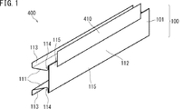
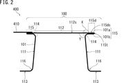
第1実施形態では、本発明の構造部材の一例について説明する。第1実施形態の構造部材400の斜視図を図1に模式的に示す。さらに、構造部材400の長手方向に垂直な断面図を、図2に模式的に示す。なお、以下では、図2における上方(天板部側)をプレス成形品100の上方と称し、図2における下方(フランジ部側)をプレス成形品100の下方と称する場合がある。
(First Embodiment)
In the first embodiment, an example of the structural member of the present invention will be described. A perspective view of the
構造部材400は、プレス成形品(P)であるプレス成形品100と、金属部材(S1)である金属部材(鋼板部材)410とを含む。図1および図2では、プレス成形品100の重ね合わせ部115dの長手方向の一部に金属部材410が固定されている一例を示す。
The
プレス成形品100は、1枚の鋼板101で形成されている。図1および図2を参照して、プレス成形品100は、2つの縦壁部111、天板部112、2つのフランジ部113、2つの突出部115を含む。縦壁部111、天板部112、およびフランジ部113はそれぞれ平板状である。天板部112は、2つの突出部115を介して2つの縦壁部111を結んでいる。図2に示す一例では、2つのフランジ部113は、2つの縦壁部111の下端部から、外側に向かってほぼ水平に延びている。すなわち、フランジ部113は、天板部112とほぼ平行である。
The press-molded
突出部115は、縦壁部111と天板部112とを結ぶ境界部(コーナー部)114から、外側に向かって突出している。突出部115のうち少なくとも先端部115t側には、重ね合わせ部115dが存在する。重ね合わせ部115dでは、天板部112から延びる鋼板101aと縦壁部111から延びる鋼板101bとが重ね合わされて密着している。鋼板101aおよび鋼板101bはそれぞれ、鋼板101の一部である。天板部112から延びる鋼板(鋼板101a)は、先端部115tにおいて逆方向に曲げられて鋼板101bとなっている。重ね合わせ部115dは、全体としては平板状である。突出部115を除いたプレス成形品100の断面(長手方向に垂直な断面)は、略ハット状である。
The projecting
図2に示すように、天板部112と重ね合わせ部115dとがなす角度を、角度Xとする。より詳細には、角度Xは、天板部112の外側表面112sを含む面と、重ね合わせ部115dの表面115ds(重ね合わせ部115dにおける鋼板101aの表面)を含む面とがなす角度をいう。図1および図2には、角度Xが180°の場合を示す。この場合、天板部112と重ね合わせ部115dとは平行である。角度Xが180°である場合の好ましい一例では、天板部112から延びる鋼板101aと天板部112との間に段差がない。なお、角度Xが180°の状態は、別の観点では、天板部112と重ね合わせ部115dとがなす角度が0°の状態であるとみなすことも可能である。
As shown in FIG. 2, the angle formed by the
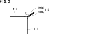
角度Xは、上述した範囲にあってもよい。角度Xが145°である場合の一例の断面図を図3に示す。 The angle X may be in the range described above. FIG. 3 shows a cross-sectional view of an example when the angle X is 145 °.
角度Xが90°より大きい場合、天板部112の上方からプレス成形品100を見たときに、突出部115を構成する鋼板101bが鋼板101aによって見えなくなっている。このような部分は、負角部と呼ばれることがある。別の観点では、負角部は、上型および下型のみでプレス成形しようとしたときに、逆勾配となる部分である。
When the angle X is larger than 90 °, when the press-molded
突出部115の長さであって境界部114から突出する長さD(図17A参照)は、上述した範囲にあってもよい。境界部114において鋼板がカーブしている場合には、そのカーブがないと仮定した場合の位置から突出部115が突出する長さを長さDとする。具体的には、縦壁部111を含む面と天板部112を含む面とが交差する位置を境界部とみなし、その位置から突出する長さを、長さDとする。
The length D of the protruding
重ね合わせ部115dは筒状に丸められていない。そのため、突出部115は、特許文献4の図6に記載の筒状に丸められた補強部とは異なる。さらに、重ね合わせ部115dでは、2枚の鋼板が密着している。また、先端部115t以外の領域において、突出部115を構成する鋼板の一部はカーブしているが折り曲げられていない。すなわち、先端部115tを除いて突出部115には、突出部115の外側に向かって突出する稜線部がない。これらの点で、プレス成形品100は、特許文献3に記載の部品とは異なる。
The overlapping
図2には、縦壁部111と天板部112とがなす角度Yが90°より大きい場合の一例を示している。ここで、角度Yは、図2に示す角度、すなわち、プレス成形品100の内側において、縦壁部111と天板部112とがなす角度である。
FIG. 2 shows an example in which the angle Y formed by the
図2に示すように、縦壁部111とフランジ部113とを結ぶコーナー部116は、丸められた形状を有することが好ましい。コーナー部116が丸められた形状を有することによって、コーナー部116で座屈することを抑制できる。
As shown in FIG. 2, the
突出部115の鋼板101bと縦壁部111との境界のコーナー部は、曲面であることが好ましい。当該コーナー部を曲面とすることによって、当該コーナー部で座屈することを抑制できる。長手方向に垂直な方向における当該コーナー部の曲率半径は、長さDの0.1〜1倍の範囲(たとえば0.2〜0.8倍の範囲や、0.2〜0.5倍の範囲)にあってもよい。角度Xが180°より小さい場合、突出部115の鋼板101aと縦壁部111との境界のコーナー部は、曲面であってもよい。
The corner portion of the boundary between the
なお、プレス成形品の長手方向の全体にわたって突出部が形成されていなくてもよい。長手方向の一部のみに突出部が形成されているプレス成形品の斜視図を、図4に模式的に示す。図4のプレス成形品100では、長手方向の両端の領域P2に突出部115が形成されておらず、長手方向の中央の領域P1に突出部115が形成されている。
It is not necessary that the protrusion is formed over the entire length of the press-molded product. FIG. 4 schematically shows a perspective view of a press-molded product in which a protrusion is formed only in a part in the longitudinal direction. In the press-molded
突出部115で二重に重ねられている鋼板は、互いに固定されていてもよい。固定方法には、プレス成形品(P)と金属部材(S1)との固定方法として例示した方法を用いてもよい。たとえば、図5に示す領域Aおよび/または領域Bが溶接されていてもよい。溶接方法に限定はない。突出部の端部ではない領域Aの溶接は、抵抗スポット溶接またはレーザー溶接で行ってもよい。突出部115と他の部分との境界にある領域Bの溶接(隅肉溶接)は、アーク溶接で行ってもよい。
The steel plates that are doubly stacked by the
図1および図2では、角度Xが180°である場合を示したが、角度Xは上述した範囲にあってもよい。角度Xが90°である場合のプレス成形品100の一例を図6に示す。さらに、図6のプレス成形品100の長手方向に垂直な断面図を、図7に模式的に示す。図6および図7の符号の意味については上述したため説明を省略する。図6および図7に示すプレス成形品100の重ね合わせ部115dには、金属部材410が固定される。
Although the case where the angle X is 180 ° is shown in FIGS. 1 and 2, the angle X may be in the above-mentioned range. FIG. 6 shows an example of the press-molded
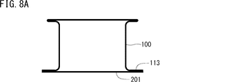
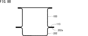
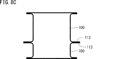
本実施形態の構造部材が、鋼板からなる他の部材(S2)を含む場合の例を、図8A〜図8Cに示す。図8A〜図8Cは、構造部材の長手方向に垂直な断面を模式的に示す図である。なお、図8A〜図8Cでは、プレス成形品100と部材(S2)とを図示し、金属部材410(金属部材(S1))の図示は省略する。上述したように、金属部材410は、プレス成形品100の重ね合わせ部に固定される。
Examples of the case where the structural member of the present embodiment includes another member (S2) made of a steel plate are shown in FIGS. 8A to 8C. 8A to 8C are views schematically showing a cross section perpendicular to the longitudinal direction of the structural member. In FIGS. 8A to 8C, the press-molded
図8A〜図8Cに示す例では、プレス成形品100と部材201とが閉断面を構成している。図8Aに示す一例では、プレス成形品100に、鋼板からなる部材(裏板)201が固定されている。部材201は、プレス成形品100の2つのフランジ部113に溶接されている。図8Bに示す一例では、プレス成形品100に、他のプレス成形品202が固定されている。プレス成形品202は、略ハット状の断面を有する。プレス成形品100とプレス成形品202とは、それぞれの内側領域が対向するように配置され、プレス成形品100のフランジ部113とプレス成形品202のフランジ部202aとが溶接されている。図8Cに示す一例では、2つのプレス成形品100が、それぞれの内側領域が対向するように配置され、お互いのフランジ部113同士が溶接されている。2つのプレス成形品100のうちの1つを部材(S2)とみなすことが可能である。また、部材201およびプレス成形品202は部材(S2)である。図8A〜図8Cでは、図1に示したプレス成形品100と同様の形状を有するプレス成形品を用いる場合について説明したが、他のプレス成形品を用いてもよい。
In the examples shown in FIGS. 8A to 8C, the press-molded
プレス成形品(P)がAピラーの下方に連なる部分を構成するプレス成形品であり、金属部材(S1)がアッパーメンバを構成する部材である場合の構造部材の一例を図9Aに模式的に示す。さらに、図9Aの線IXB−IXBにおける断面図を図9Bに模式的に示す。 FIG. 9A schematically shows an example of a structural member in the case where the press-molded product (P) is a press-molded product constituting a portion connected below the A pillar and the metal member (S1) is a member constituting the upper member. Shown. Further, a cross-sectional view taken along the line IXB-IXB of FIG. 9A is schematically shown in FIG. 9B.
図9Aおよび図9Bに示す構造部材400aにおいて、プレス成形品100aは、Aピラーの下方に連なる部分を構成するプレス成形品である。プレス成形品100aのフランジ部には、閉断面を構成するように部材(S2)である部材201aが固定されている。金属部材410aは、アッパーメンバを構成する部材である。金属部材410aは、固定部420において、重ね合わせ部115dに固定されている。抵抗スポット溶接を用いた場合、固定部420はナゲットである。
In the
自動車の組立てでは、プレス成形品(P)に部材(S2)を溶接して閉断面部材(中空体)を形成した後に金属部材(S1)を溶接する場合が多い。重ね合わせ部がない従来のプレス成形品では、天板部112に金属部材410を溶接する必要がある。その場合、部材201を溶接した後に金属部材410を両側スポット溶接によって天板部112に溶接することは難しい。これは、長尺の閉断面部材(筒状体など)に対して両側スポット溶接を行う場合に常に問題となる。一方、プレス成形品100は重ね合わせ部115dを有する。そのため、図9Cに示すように、プレス成形品100に部材201を溶接して中空体を形成した後であっても、溶接部位の両側から2つの電極(電極棒)51aおよび51bを溶接部位に到達させることができ、両側スポット溶接を容易に実施できる。さらに、両側スポット溶接に限らず、他の固定方法についても適用が容易である。そのため、プレス成形品100を用いることによって、金属部材410をプレス成形品100に固定する自由度が格段に高くなる。
In the assembly of automobiles, a member (S2) is often welded to a press-molded product (P) to form a closed cross-section member (hollow body), and then a metal member (S1) is welded. In the conventional press-molded product having no overlapping portion, it is necessary to weld the
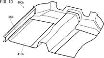
プレス成形品(P)がサイドシルインナであり、金属部材(S1)がフロアパネルである場合の構造部材の一例の斜視図を、図10に模式的に示す。なお、図10は、フロアパネルの一部のみを示している。 FIG. 10 schematically shows a perspective view of an example of a structural member when the press-molded product (P) is a side sill inner and the metal member (S1) is a floor panel. Note that FIG. 10 shows only a part of the floor panel.
図10の構造部材400bにおいて、プレス成形品100bはサイドシルインナであり、金属部材410bはフロアパネルである。金属部材410bは、プレス成形品100bの重ね合わせ部に固定されている。
In the
(第2実施形態)
上述したように、金属部材(S1)は、縦壁部および天板部のいずれか一方、および、重ね合わせ部の2箇所でプレス成形品に固定されていてもよい。第2実施形態では、そのような構造部材の一例について説明する。なお、第1実施形態で説明した構造部材について、第2実施形態の構成を適用することが可能である。
(Second Embodiment)
As described above, the metal member (S1) may be fixed to the press-molded product at either one of the vertical wall portion and the top plate portion and at two locations of the overlapping portion. In the second embodiment, an example of such a structural member will be described. It is possible to apply the configuration of the second embodiment to the structural members described in the first embodiment.
第2実施形態の構造部材の一例の断面図を、図11Aに模式的に示し、他の一例の断面図を図11Bに模式的に示す。図11Aおよび図11Bに示す構造部材400では、金属部材410が、固定部420aおよび固定部420bの2箇所でプレス成形品100に固定されている。図11Aの構造部材では、固定部420aは天板部112に形成され、固定部420bは重ね合わせ部115dに形成される。この場合、固定部420aが形成されている部分(天板部112)と固定部420bが形成されている部分(重ね合わせ部115d)とがなす角度は、上述した角度Xである。
A cross-sectional view of an example of the structural member of the second embodiment is schematically shown in FIG. 11A, and a cross-sectional view of another example is schematically shown in FIG. 11B. In the
図11Bの構造部材400では、固定部420aは縦壁部111に形成され、固定部420bは重ね合わせ部115dに形成される。この場合、固定部420aが形成されている部分(縦壁部111)と固定部420bが形成されている部分(重ね合わせ部115d)とがなす角度は、上述した角度XおよびYを用いると、(360−X−Y)度で表される。
In the
固定部420aが形成されている部分(縦壁部111または天板部112)と、固定部420aが形成されている部分(重ね合わせ部115d)とがなす角度を、180°以外(たとえば上述した範囲)とすることによって、固定部の信頼性を高めることができる。
The angle formed by the portion where the fixed
スポット溶接継手の破断モードは、引張せん断(TSS)のモード、L字継手(LTS)のモード、十字継手(CTS)のモードに大きく分けられる。一般的に、継手の強度は、TSSが最も高く、LTS、CTSの順に低くなる。しかし、衝突時には様々な方向から力が加わるため、一般的なスポット溶接継手では、破断モードをコントロールすることは困難である。 The fracture mode of the spot welded joint is roughly divided into a tensile shear (TSS) mode, an L-shaped joint (LTS) mode, and a cross joint (CTS) mode. In general, the strength of the joint is highest in TSS and decreases in the order of LTS and CTS. However, it is difficult to control the fracture mode with a general spot welded joint because forces are applied from various directions at the time of collision.
図12Aおよび図12Bはそれぞれ、図11Aに示した構造部材について、プレス成形品100と金属部材410とに、矢印の方向に引き離す力が加わった場合を示す。図12Aおよび図12Bのいずれの場合でも、固定部420aおよび420bの少なくとも一方の破断モードがTSSモードとなる。そのため、第2実施形態の構造部材によればより高い接合強度が得られ、その結果、高い衝突安全性を実現することが可能になる。
12A and 12B, respectively, show the case where the press-molded
(第3実施形態)
第3実施形態では、本実施形態の構造部材を製造するための方法について説明する。第3実施形態では、第1および第2の実施形態で説明したプレス成形品を製造する一例について説明するが、本発明の他のプレス成形品も同様の方法で製造できる。第3実施形態では、第2工程をホットスタンピングによって行う一例について説明する。
(Third Embodiment)
In the third embodiment, a method for manufacturing the structural member of the present embodiment will be described. In the third embodiment, an example of producing the press-molded product described in the first and second embodiments will be described, but other press-molded products of the present invention can also be produced in the same manner. In the third embodiment, an example in which the second step is performed by hot stamping will be described.
まず、第1工程では、2つの縦壁部111となる部分および天板部112となる部分を含む予備成形品301を、素材鋼板を変形させることによって形成する。第1工程は、上述した方法(たとえばプレス加工)によって行うことができる。第1工程で形成される予備成形品301の一例の断面(長手方向に垂直な断面)を、図13に模式的に示す。
First, in the first step, the preformed
予備成形品301は、U字状部301aと、フランジ部113となる平坦部301bとを含む。U字状部301aは、2つの縦壁部111および天板部112となる部分を含み、さらに、突出部115となる部分(余剰部301ae)を含む。予備成形品301の断面は、略ハット状である。また、U字状部301aの断面は、略U字状(図13では上下が逆)である。
The
U字状部301aの長さ(断面長さ)をLuとする。さらに、プレス成形品において、縦壁部の高さをHb(図11AのHb1に相当)とし、2つの縦壁部間の幅をWb(図11AのWb1に相当)とする。U字状部301aは、縦壁部111となる部分および天板部112となる部分に加えて、第2工程によって突出部115となる余剰部301aeを含む。そのため、長さLu、幅Wb、および高さHbは、Wb+2Hb<Luの関係を満たす。さらに、U字状部301aの幅をWaとし高さをHaとする。通常、Wb≦Waの関係とWb+2Hb<Wa+2Haの関係とが満たされる。なお、図13に示す予備成形品301のU字状部301aでは、余剰部301aeと他の部分との間には明確な境界がない。
Let the length (cross-sectional length) of the
予備成形品301の平坦部301bの端部は下方(天板部112から離れる方向)に下がっていてもよい。以下の図14A〜図14Dでは、平坦部301bの端部が下がっていない予備成形品301を用いて第2工程を行う一例について説明する。図15A〜図15Dに示すように、平坦部301bの端部が下がっている予備成形品301でも同様に成形が可能である。
The end portion of the
第2工程は、ホットスタンピングによって行われる。まず、予備成形品301を、Ac3変態点以上の温度(たとえばAc3変態点より80℃以上高い温度)にまで加熱する。この加熱は、たとえば、予備成形品301を加熱装置内で加熱することによって行われる。
The second step is performed by hot stamping. First, the preformed
次に、加熱された予備成形品301をプレス装置によってプレス加工する。プレス加工に用いられるプレス型の構成の一例を図14Aに示す。プレス装置は、一対のプレス型10、プレート13、伸縮機構14、カム押圧型15、およびカム型(スライド型)21を含む。一対のプレス型10は、上型11と下型12とを含む。下型12は、凸部12aを含む。カム押圧型15およびカム型21はそれぞれ、カム機構として働く傾斜面15aおよび21aを有する。カム押圧型15は、伸縮可能な伸縮機構14を介してプレート13に固定されている。伸縮機構には、バネおよび油圧シリンダ等の公知の伸縮機構を用いることができる。
Next, the heated
プレート13の下降に伴って、上型11およびカム押圧型15が下降する。カム押圧型15の下降に伴い、カム型21がカム押圧型15に押されて下型12の凸部12a側に移動する。よく知られているように、カム型21の移動のタイミングは、傾斜面15aおよび21aの位置および形状を変化させることによって調整できる。すなわち、それらの調整によって、上述した工程(a)の完了および工程(b)の完了のタイミングを調整できる。なお、カム機構を用いずに、油圧シリンダ等によってカム型21を移動させてもよい。
As the
この実施形態では、上型11とカム押圧型15とがプレート13を介してプレス機の同じスライドに取り付けられている一例について例示している。しかし、上型11とカム押圧型15とをプレス機の別々のスライドに取り付け、それらを個別に動作させてもよい。また、この実施形態では、カム押圧型15が押し当てられることによってカム型21が移動する一例について例示している。しかし、カム型21に直接取り付けた駆動装置によってカム型21を移動させてもよい。
In this embodiment, an example is illustrated in which the
プレス型10およびカム型21は、冷却可能である。たとえば、プレス型10およびカム型21は、それらの内部を冷却水が循環するように構成されてもよい。冷却された金型を用いてプレスを行うことによって、加熱された予備成形品301が成形および冷却される。その結果、プレス成形と焼入れとが行われる。なお、金型から水を噴出させることによって冷却を行ってもよい。
The
図14Aの装置を用いてプレス成形する工程の一例について説明する。図14A〜図14Dに、上述した第2の例の方法で第2工程を行う場合の一例を模式的に示す。この第2の例の方法は、角度Xが135°以上(たとえば135°〜180°の範囲)である場合に好ましく用いられる。 An example of a step of press molding using the apparatus of FIG. 14A will be described. 14A to 14D schematically show an example in which the second step is performed by the method of the second example described above. The method of this second example is preferably used when the angle X is 135 ° or more (for example, in the range of 135 ° to 180 °).
まず、図14Aに示すように、上型11と下型12との間に予備成形品301を配置する。次に、プレート13を下降させる。カム型21は、プレート13に伴って下降するカム押圧型15に押され、凸部12a側にスライドする。その結果、図14Bに示すように、下型12(凸部12a)とカム型21とが、縦壁部111となる部分をプレスして拘束する。このようにして、工程(b)が完了する。
First, as shown in FIG. 14A, the
次に、図14Cに示すように、プレート13をさらに下降させ、それによって天板部となる部分のプレスを開始する。このとき、伸縮機構14が縮む。予備成形品301は余剰部を有するため、その余剰部がカム型21側に張り出す。
Next, as shown in FIG. 14C, the
次に、図14Dに示すように、上型11を下死点まで下降させ、天板部となる部分を上型11と下型12(凸部12a)とでプレスして拘束する。このようにして、工程(a)が完了する。以上のようにして、プレス成形が完了する。余剰部は、上型11とカム型21との間で折り重ねられて、重ね合わせ部115dを有する突出部115となる。このようにして、プレス成形品100が得られる。
Next, as shown in FIG. 14D, the
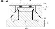
次に、上述した第1の例の方法で第2工程を行う場合の一例について説明する。図15A〜図15Dに、各工程を模式的に示す。この第1の例の方法は、角度Xが135°以下(たとえば90°〜135°の範囲)である場合に好ましく用いられる。 Next, an example in which the second step is performed by the method of the first example described above will be described. 15A to 15D schematically show each step. The method of this first example is preferably used when the angle X is 135 ° or less (for example, in the range of 90 ° to 135 °).
図15A〜図15Dでは、フランジ部113となる平坦部301b(図13参照)の端部が下方に曲がっており、下型12がそれに対応する形状を有する場合について示す。このような構成によれば、平坦部301bの端部を、カム型21の下面と下型12との間に入れることが容易になる。もちろん、図14A〜図14Dに示すように、平坦部301bの端部が下方に曲がっていなくてもよい。すなわち、本発明の製造方法において、予備成形品のうちフランジ部となる部分の端部が、下方に曲がっていてもよいし、曲がっていなくてもよい。フランジ部となる部分の端部が下方に曲がっている場合、それに対応する凹部が下型に形成されていてもよい。
15A to 15D show a case where the end portion of the
図15Aに示す装置では、伸縮可能な伸縮機構14を介して上型11がプレート13に固定されている。一方、カム押圧型15は、伸縮機構14を介さずにプレート13に固定されている。
In the device shown in FIG. 15A, the
この第2工程では、まず、図15Aに示すように、上型11と下型12との間に予備成形品301を配置する。次に、図15Bに示すように、プレート13を下降させ、上型11と下型12(凸部12a)とによって、天板部となる部分をプレスして拘束する。このようにして、工程(a)が完了する。
In this second step, first, as shown in FIG. 15A, the preformed
次に、伸縮機構14を収縮させながらプレート13をさらに下降させる。これによって、図15Cに示すように、カム型21を凸部12a側にスライドさせる。予備成形品301は余剰部を有するため、その余剰部が上方に張り出す。
Next, the
次に、図15Dに示すように、プレート13を下死点まで下降させ、カム型21と下型12(凸部12a)とによって縦壁部となる部分をプレスして拘束する。このとき、余剰部は、上型11とカム型21との間で折り重ねられて突出部115となる。このようにして、工程(b)が完了する。以上のようにしてプレス成形が完了し、プレス成形品100が得られる。
Next, as shown in FIG. 15D, the
第2工程の第3の例として上述したように、第2工程において、工程(a)および工程(b)を同時に完了させてもよい。金型の形状および配置を調整することによって、工程(a)および工程(b)を同時に完了させることができる。 As described above as a third example of the second step, the steps (a) and (b) may be completed at the same time in the second step. By adjusting the shape and arrangement of the molds, steps (a) and (b) can be completed at the same time.
ホットスタンピングによって第2工程を行う場合、第2工程において適正な焼入れを行うために、金型(プレス型10およびカム型21)の移動が完了した時点で、それらの金型とプレス成形品100とが密着していることが好ましい。第2工程で得られたプレス成形品100は、必要に応じて後処理がなされる。得られた成形品は、必要に応じて他の部品と組み合わされて用いられる。
When the second step is performed by hot stamping, when the movement of the dies (press dies 10 and cam dies 21) is completed in order to perform proper quenching in the second step, those dies and the press molded
第2工程は、一対のプレス型(上型および下型)の少なくとも一方から突出するピンを含むプレス型を用いて行ってもよい。そのような第2工程の一例を、図16に模式的に示す。図16のプレス型は、下型12の凸部12aから突出するピン16を含む。上型11には、上型11が下降したときにピン16が挿入される穴11hが形成されている。ピン16は、予備成形品301に形成された貫通孔に挿入される。その状態で第2工程のプレス成形を行うことによって、突出部を精度よく形成できる。なお、プレス型は、ピン16が上方から押圧されたときにピン16の少なくとも一部が下型12内に収納される機構を有してもよい。
The second step may be performed using a press die including a pin protruding from at least one of a pair of press dies (upper die and lower die). An example of such a second step is schematically shown in FIG. The press die of FIG. 16 includes a
次に、第3工程では、プレス成形品100の重ね合わせ部115dに、金属部材(S1)を固定する。固定方法には、上述した方法を適用することができ、プレス成形品100の形状や用途に応じて選択すればよい。
Next, in the third step, the metal member (S1) is fixed to the overlapping
本実施形態の構造部材が部材(S2)を含む場合、部材(S2)の固定は、金属部材(S1)の固定の前であってもよいし、後であってもよい。部材(S2)の固定も、上述した方法を適用することができ、プレス成形品100の形状や用途に応じて選択すればよい。
When the structural member of the present embodiment includes the member (S2), the member (S2) may be fixed before or after the metal member (S1) is fixed. The above-mentioned method can also be applied to the fixing of the member (S2), which may be selected according to the shape and application of the press-molded
以上のようにして、本実施形態の構造部材が得られる。もちろん、第3工程で得られた構造部材をさらに加工してから自動車の構造部材として用いてもよい。 As described above, the structural member of the present embodiment is obtained. Of course, the structural member obtained in the third step may be further processed and then used as a structural member of an automobile.
本発明について、実施例によってより詳細に説明する。 The present invention will be described in more detail by way of examples.
(実施例1)
実施例1では、プレス成形品(P)と部材(S2)とからなる構造体について、三点曲げ試験のシミュレーションを行った。シミュレーションには、汎用のFEM(有限要素法)ソフト(LIVERMORE SOFTWARE TECHNOLOGY社製、商品名LS‐DYNA)を用いた。プレス成形品(P)を含む構造体としてシミュレーションに用いたサンプル1の断面図を、図17Aに模式的に示す。図17Aの構造体は、プレス成形品100と、そのフランジ部113に溶接された部材(裏板)201とからなる。図17Aに示したサンプル1のサイズは以下の通りである。ただし、以下のサイズにおいては鋼板の厚さは考慮していない。
・角度X:180°
・角度Y:90°
・突出部の長さD:15mm
・縦壁部の高さHb1:60mm
・2つの突出部の先端部間の幅Wt1:80mm
・2つの縦壁部間の距離(天板部の幅)Wb1:50mm(80−2D)
・裏板の幅Wp1:90mm(120−2D)
・コーナー部RaおよびRbにおける曲率半径:5mm
・長手方向の長さ:1000mm
(Example 1)
In Example 1, a simulation of a three-point bending test was performed on a structure composed of a press-molded product (P) and a member (S2). For the simulation, general-purpose FEM (finite element method) software (manufactured by LIVERMORE SOFTWARE TECHNOLOGY, trade name LS-DYNA) was used. FIG. 17A schematically shows a cross-sectional view of
・ Angle X: 180 °
・ Angle Y: 90 °
・ Length of protrusion D: 15 mm
・ Height of vertical wall Hb1: 60mm
-Width between the tips of the two protrusions Wt1: 80 mm
-Distance between two vertical walls (width of top plate) Wb1: 50 mm (80-2D)
-Back plate width Wp1: 90 mm (120-2D)
-Radius of curvature at corners Ra and Rb: 5 mm
・ Longitudinal length: 1000 mm
また、従来例の構造体としてシミュレーションに用いたサンプル2およびサンプル3の断面図を図17Bおよび図17Cに模式的に示す。図17Bに示すサンプル2は、断面がハット型のプレス成形品1と、そのフランジ部1cに溶接された裏板2とからなる。プレス成形品1は、天板部1a、縦壁部1b、およびフランジ部1cからなる。図17Bに示したサンプル2のサイズは以下の通りである。
・天板部1aの幅:80mm
・縦壁部1bの高さ:60mm
・裏板2の幅:120mm
・コーナー部における曲率半径:5mm
・長手方向の長さ:1000mm
Further, sectional views of
-Width of
-Height of
-Width of back plate 2: 120 mm
・ Radius of curvature at corners: 5 mm
・ Longitudinal length: 1000 mm
サンプル2とサンプル3とは、全く同じ構造を有し、配置のみが異なる。具体的には、サンプル2は、裏板2側が上方(インパクタ側)に配置されており、サンプル3は天板部1a側が上方(インパクタ側)に配置されている。以下では、裏板側が上方にある配置(サンプル2の配置)を逆ハットの配置と称する。さらに、天板部側が上方にある配置(サンプル3の配置)を正ハットの配置と称する。なお、後述するように、実際の構造部材で起きる衝突は、主に正ハットの配置で起きる。そのため、サンプル1の比較例となるのは、正ハット配置のサンプル3であり、逆ハット配置のサンプル2は参考例として記載している。
サンプル1〜3は、厚さが1.4mmで引張強度が1500MPaである鋼板からなるものであると仮定した。プレス成形品のフランジ部と裏板とは、40mmのピッチでスポット溶接して固定したと仮定した。サンプル1〜3は、長手方向における単位長さあたりの質量が同じになるように設計した。
シミュレーションで用いた三点曲げ試験の方法を図18に模式的に示す。三点曲げ試験は、2つの支点5にサンプルを載せ、インパクタ6によって上方からサンプルを押すことによって行った。実施例1の試験において、2つの支点5の間の距離Sは400mmまたは700mmとした。支点5の曲率半径は30mmとした。インパクタ6の曲率半径は150mmとした。インパクタ6の衝突速度は7.5km/hとした。
The method of the three-point bending test used in the simulation is schematically shown in FIG. The three-point bending test was performed by placing the sample on the two
三点曲げ試験では、各サンプルの上方からインパクタ6を衝突させた。具体的には以下の表1に示す6種類の試験を行った。インパクタ6の衝突方向を、図17A〜図17C中の矢印で示す。
In the three-point bending test, the

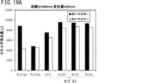
試験1−1〜1−3および2−1〜2−3において、変位量が100mmのときの、各サンプルのエネルギ吸収量を求めた。その結果を、図19Aおよび図19Bに示す。図19Aは、試験1−1〜1−3(距離S=400mm)の結果を示し、図19Bは、試験2−1〜2−3(距離S=700mm)の結果を示す。エネルギ吸収量が大きい自動車構造部品は、衝突に対する乗員の安全性が高いことを意味する。 In tests 1-1 to 1-3 and 2-1 to 2-3, the amount of energy absorbed by each sample when the displacement amount was 100 mm was determined. The results are shown in FIGS. 19A and 19B. FIG. 19A shows the results of tests 1-1 to 1-3 (distance S = 400 mm), and FIG. 19B shows the results of tests 2-1 to 2-3 (distance S = 700 mm). Automobile structural parts that absorb a large amount of energy mean that the safety of occupants in a collision is high.
図19Aおよび図19Bには、サンプル1の突出部の長さDを、5mm、10mm、15mm、および20mmとした場合の結果についても示す。長さDが5mmの場合は、突出部の先端部のみが重ね合わせ部となる。なお、いずれのサンプルも、長手方向の単位長さあたりの質量は同じになるように設計した。さらに、それらの図には、鋼板の割れおよびスポット溶接の部分における割れを考慮しないシミュレーション結果と、それらを考慮したシミュレーション結果とについても示す。
19A and 19B also show the results when the length D of the protrusion of the
図19Aおよび図19Bに示すように、突出部を有するサンプル1はいずれも、正ハット配置のサンプル3(比較例)よりもエネルギ吸収量が大きかった。さらに、割れを考慮した場合、サンプル1は多くの場合でサンプル2(参考例)よりも高い特性を示した。図19Aは、支点間距離Sが400mmの場合には突出部の長さDを10mm以上とすることが好ましいことを示している。図19Bは、支点間距離Sが700mmの場合には突出部の長さDが長い方が好ましいことを示している。
As shown in FIGS. 19A and 19B, the energy absorption amount of each of the
図19Aおよび図19Bに示されるように、サンプル2(逆ハット配置)の結果において、鋼板およびスポット溶接の割れを考慮した場合のエネルギ吸収量は、それらを考慮しない場合のエネルギ吸収量よりも大きく低下した。この結果は、裏板側からインパクタ6が衝突した場合、割れ(たとえばスポット溶接部分における割れ)が生じやすいことを示唆している。
As shown in FIGS. 19A and 19B, in the result of sample 2 (reverse hat arrangement), the energy absorption amount when the cracks of the steel plate and the spot weld are taken into consideration is larger than the energy absorption amount when they are not taken into consideration. It has decreased. This result suggests that when the
断面が略ハット状のプレス成形品を自動車その他の構造部材として用いる場合、天板部側がボディーの外側に向けて配置されることが多い。そのため、事故時の衝突は、裏板側からではなく天板部側から生じることを想定する必要がある。その点で、逆ハット配置のサンプル2の特性が良好であったとしても、実際に構造部材として適用する場合には意味がない場合が多い。そのため、天板部側からの衝突に対する特性が重要である。天板部側からの衝突で比較した場合、サンプル1は、正ハット配置のサンプル3に対して非常に優れた特性を示した。そのため、プレス成形品(P)を用いた構造部材は、衝突安全性の向上に非常に有用である。
When a press-molded product having a substantially hat-shaped cross section is used as an automobile or other structural member, the top plate side is often arranged toward the outside of the body. Therefore, it is necessary to assume that the collision at the time of an accident occurs not from the back plate side but from the top plate side. In that respect, even if the characteristics of the
(実施例2)
実施例2では、サンプル1(D=15mm)の角度Xのみを変化させたサンプル(サンプル1’)について、実施例1と同様に三点曲げ試験のシミュレーションを行った。サンプル1’の角度Xは、90°、105°、120°、135°、および180°とした。角度Xが90°である場合のサンプル1’に含まれるプレス成形品(P)の形状は、図7に示すプレス成形品100と同様の形状である。
(Example 2)
In Example 2, a three-point bending test was simulated in the same manner as in Example 1 for a sample (Sample 1') in which only the angle X of Sample 1 (D = 15 mm) was changed. The angles X of sample 1'were 90 °, 105 °, 120 °, 135 °, and 180 °. The shape of the press-molded product (P) included in the sample 1'when the angle X is 90 ° is the same as that of the press-molded
変位量が100mmのときの各サンプルのエネルギ吸収量を、シミュレーションによって求めた。支点間距離Sが400mmである場合の結果を図20Aに示す。支点間距離Sが700mmである場合の結果を図20Bに示す。なお、実施例2のシミュレーションでは、鋼板の割れおよびスポット溶接部分の割れを考慮しなかった。 The energy absorption amount of each sample when the displacement amount was 100 mm was obtained by simulation. The result when the distance S between the fulcrums is 400 mm is shown in FIG. 20A. The result when the distance S between the fulcrums is 700 mm is shown in FIG. 20B. In the simulation of Example 2, cracks in the steel plate and cracks in the spot welded portion were not considered.
図20Aおよび図20Bに示されるように、角度Xが変化しても、サンプル1’は正ハット配置のサンプル3よりも良好な特性を示した。図20Aに示されるように、支点間距離Sが400mmの場合には、角度Xが大きいほどエネルギ吸収量が大きかった。一方、図20Bに示されるように、支点間距離Sが700mmの場合には、角度Xが小さいほどエネルギ吸収量が大きかった。 As shown in FIGS. 20A and 20B, sample 1'showed better properties than sample 3 in the positive hat arrangement even when the angle X changed. As shown in FIG. 20A, when the distance S between the fulcrums was 400 mm, the larger the angle X, the larger the amount of energy absorbed. On the other hand, as shown in FIG. 20B, when the distance S between the fulcrums was 700 mm, the smaller the angle X, the larger the amount of energy absorbed.
実施例1の試験において、インパクタの衝突によって変位したサンプル1の断面形状を図21Aに示す。サンプル1では縦壁部が内側に倒れており、それによって荷重を受けとめている。これは、角度Xが90°よりも大きいためである。実施例2の試験において、インパクタの衝突によって変位したサンプル1’の断面形状を図21Bに示す。図21Bに示すのは、角度X=90°のサンプル1’である。図21Bに示すように、角度X=90°の場合、サンプル1’の外側の鋼板(突出部のうちの外側の鋼板および縦壁部の鋼板)は全体で荷重を受けとめている。
FIG. 21A shows the cross-sectional shape of the
以上のように、プレス成形品(P)を用いることによって、自動車の衝突安全性を高めることが可能な構造部材が得られる。さらに、プレス成形品の重ね合わせ部に金属部材(S1)を固定することによって、製造の自由度および固定部の信頼性が高い構造部材が得られる。 As described above, by using the press-molded product (P), a structural member capable of enhancing the collision safety of an automobile can be obtained. Further, by fixing the metal member (S1) to the superposed portion of the press-molded product, a structural member having a high degree of freedom in manufacturing and the reliability of the fixed portion can be obtained.
本発明は、自動車用の構造部材に利用できる。 The present invention can be used for structural members for automobiles.
10:一対のプレス型
11:上型(プレス型)
12:下型(プレス型)
100:プレス成形品
101、101a、101b:鋼板
111:縦壁部
112:天板部
113:フランジ部
114:境界部
115:突出部
115d:重ね合わせ部
200a、200b、200c:構造部材(自動車部品)
201:他の部材
301:予備成形品
301ae:余剰部
400:構造部材
410:金属部材
D:突出部の長さであって境界部から突出する長さ
X:天板部と重ね合わせ部とがなす角度
10: Pair of press molds 11: Upper mold (press mold)
12: Lower mold (press mold)
100: Press-molded
201: Other members 301: Pre-molded product 301ae: Surplus part 400: Structural member 410: Metal member D: Length of the protruding part and protruding from the boundary part X: Top plate part and overlapping part Angle to make
Claims (11)
1枚の鋼板で形成されたプレス成形品と、前記プレス成形品に固定された、金属板からなる金属部材とを含み、
前記プレス成形品は、
2つの縦壁部と、
前記2つの縦壁部を結ぶ天板部と、
前記縦壁部と前記天板部とを結ぶ2つの境界部のうちの少なくとも1つの境界部から突出する突出部と、を含み、
前記突出部は、その少なくとも先端に前記鋼板が折り重ねられた重ね合わせ部を有して、前記境界部から突出しており、
前記金属部材が前記重ね合わせ部に固定されている、自動車用の構造部材。 A structural member for automobiles
A press-molded product formed of a single steel plate and a metal member made of a metal plate fixed to the press-molded product are included.
The press-molded product is
Two vertical walls and
The top plate that connects the two vertical walls and
Including a protruding portion protruding from at least one boundary portion of the two boundary portions connecting the vertical wall portion and the top plate portion.
Before SL protrusions have overlapping portions in which the steel sheet to at least the tip is folded in its protrudes from the boundary,
A structural member for an automobile in which the metal member is fixed to the overlapping portion.
前記金属部材が固定された前記縦壁部または前記天板部と前記重ね合わせ部とがなす角度が、90°〜175°の範囲にある、請求項1または2に記載の、自動車用の構造部材。 The metal member is fixed to the press-molded product at one of the vertical wall portion and the top plate portion, and at two locations of the overlapping portion.
The structure for an automobile according to claim 1 or 2, wherein the angle formed by the vertical wall portion or the top plate portion to which the metal member is fixed and the overlapping portion is in the range of 90 ° to 175 °. Element.
前記プレス成形品と前記他の部材とが閉断面を構成するように、前記他の部材が前記2つのフランジ部に固定されている、請求項7に記載の、自動車用の構造部材。 Including other members consisting of metal plates
The structural member for an automobile according to claim 7, wherein the other member is fixed to the two flange portions so that the press-molded product and the other member form a closed cross section.
前記金属部材は、アッパーメンバを構成する部材である、請求項1〜7のいずれか1項に記載の、自動車用の構造部材。 The press-molded product is a press-molded product that constitutes a portion connected below the A-pillar.
The structural member for an automobile according to any one of claims 1 to 7, wherein the metal member is a member constituting an upper member.
前記金属部材はフロアパネルである、請求項1〜7のいずれか1項に記載の、自動車用の構造部材。 The press-molded product is a side sill inner and
The structural member for an automobile according to any one of claims 1 to 7, wherein the metal member is a floor panel.
前記2つの縦壁部となる部分および前記天板部となる部分を含む予備成形品を、素材鋼板を変形させることによって形成する第1工程と、
前記予備成形品をプレス成形することによって、前記プレス成形品を形成する第2工程と、
前記プレス成形品の前記重ね合わせ部に前記金属部材を固定する第3工程と、を含み、
前記予備成形品は、前記突出部を形成するための余剰部を含み、
前記第2工程において、前記余剰部を構成する前記素材鋼板の少なくとも一部を折り重ねて、重ね合わせることによって前記重ね合わせ部を形成する、自動車用の構造部材の製造方法。 The method for manufacturing a structural member for an automobile according to any one of claims 1 to 10.
The first step of forming a preformed product including the two vertical wall portions and the top plate portion by deforming the material steel plate.
The second step of forming the press-molded product by press-molding the pre-molded product, and
A third step of fixing the metal member to the overlapping portion of the press-molded product is included.
The premolded article includes a surplus portion for forming the protrusion.
A method for manufacturing a structural member for an automobile, wherein in the second step, at least a part of the material steel sheet constituting the surplus portion is folded and overlapped to form the overlapped portion.
Priority Applications (1)
| Application Number | Priority Date | Filing Date | Title |
|---|---|---|---|
| JP2016222818A JP6794792B2 (en) | 2016-11-16 | 2016-11-16 | Structural members for automobiles and their manufacturing methods |
Applications Claiming Priority (1)
| Application Number | Priority Date | Filing Date | Title |
|---|---|---|---|
| JP2016222818A JP6794792B2 (en) | 2016-11-16 | 2016-11-16 | Structural members for automobiles and their manufacturing methods |
Publications (2)
| Publication Number | Publication Date |
|---|---|
| JP2018079779A JP2018079779A (en) | 2018-05-24 |
| JP6794792B2 true JP6794792B2 (en) | 2020-12-02 |
Family
ID=62197475
Family Applications (1)
| Application Number | Title | Priority Date | Filing Date |
|---|---|---|---|
| JP2016222818A Active JP6794792B2 (en) | 2016-11-16 | 2016-11-16 | Structural members for automobiles and their manufacturing methods |
Country Status (1)
| Country | Link |
|---|---|
| JP (1) | JP6794792B2 (en) |
Cited By (2)
| Publication number | Priority date | Publication date | Assignee | Title |
|---|---|---|---|---|
| US12509155B2 (en) | 2021-11-09 | 2025-12-30 | Hyundai Motor Company | Vehicle center frame module |
| JP7799232B1 (en) * | 2025-05-27 | 2026-01-15 | 日本製鉄株式会社 | Die, hot press device, and method for manufacturing hot press-molded product |
Families Citing this family (1)
| Publication number | Priority date | Publication date | Assignee | Title |
|---|---|---|---|---|
| JP6760539B1 (en) * | 2019-10-09 | 2020-09-23 | 日本製鉄株式会社 | Molded products, structural members using them, and methods for manufacturing molded products |
-
2016
- 2016-11-16 JP JP2016222818A patent/JP6794792B2/en active Active
Cited By (2)
| Publication number | Priority date | Publication date | Assignee | Title |
|---|---|---|---|---|
| US12509155B2 (en) | 2021-11-09 | 2025-12-30 | Hyundai Motor Company | Vehicle center frame module |
| JP7799232B1 (en) * | 2025-05-27 | 2026-01-15 | 日本製鉄株式会社 | Die, hot press device, and method for manufacturing hot press-molded product |
Also Published As
| Publication number | Publication date |
|---|---|
| JP2018079779A (en) | 2018-05-24 |
Similar Documents
| Publication | Publication Date | Title |
|---|---|---|
| JP6468369B2 (en) | Hot stamp molded article, structural member using the same, and method for manufacturing hot stamp molded article | |
| JP6659733B2 (en) | Manufacturing method of hot stamped product | |
| JP6791370B2 (en) | Structural members for automobiles and their manufacturing methods | |
| JP6769546B2 (en) | Press-molded products, structural members for automobiles using them, and methods for manufacturing press-molded products. | |
| JP6760539B1 (en) | Molded products, structural members using them, and methods for manufacturing molded products | |
| JP6794792B2 (en) | Structural members for automobiles and their manufacturing methods | |
| JP6760554B1 (en) | Molded products, structural members using them, and methods for manufacturing molded products | |
| JP7155923B2 (en) | Molded product manufacturing method | |
| JP7248932B2 (en) | Molded product manufacturing method |
Legal Events
| Date | Code | Title | Description |
|---|---|---|---|
| A621 | Written request for application examination |
Free format text: JAPANESE INTERMEDIATE CODE: A621 Effective date: 20190703 |
|
| A131 | Notification of reasons for refusal |
Free format text: JAPANESE INTERMEDIATE CODE: A131 Effective date: 20200714 |
|
| A977 | Report on retrieval |
Free format text: JAPANESE INTERMEDIATE CODE: A971007 Effective date: 20200716 |
|
| A521 | Written amendment |
Free format text: JAPANESE INTERMEDIATE CODE: A523 Effective date: 20200819 |
|
| TRDD | Decision of grant or rejection written | ||
| A01 | Written decision to grant a patent or to grant a registration (utility model) |
Free format text: JAPANESE INTERMEDIATE CODE: A01 Effective date: 20201013 |
|
| A61 | First payment of annual fees (during grant procedure) |
Free format text: JAPANESE INTERMEDIATE CODE: A61 Effective date: 20201026 |
|
| R151 | Written notification of patent or utility model registration |
Ref document number: 6794792 Country of ref document: JP Free format text: JAPANESE INTERMEDIATE CODE: R151 |