JP6793263B2 - Multipurpose eco cap - Google Patents
Multipurpose eco cap Download PDFInfo
- Publication number
- JP6793263B2 JP6793263B2 JP2019547052A JP2019547052A JP6793263B2 JP 6793263 B2 JP6793263 B2 JP 6793263B2 JP 2019547052 A JP2019547052 A JP 2019547052A JP 2019547052 A JP2019547052 A JP 2019547052A JP 6793263 B2 JP6793263 B2 JP 6793263B2
- Authority
- JP
- Japan
- Prior art keywords
- main body
- ring
- cap
- container
- bent portion
- Prior art date
- Legal status (The legal status is an assumption and is not a legal conclusion. Google has not performed a legal analysis and makes no representation as to the accuracy of the status listed.)
- Active
Links
Images


Classifications
-
- B—PERFORMING OPERATIONS; TRANSPORTING
- B65—CONVEYING; PACKING; STORING; HANDLING THIN OR FILAMENTARY MATERIAL
- B65D—CONTAINERS FOR STORAGE OR TRANSPORT OF ARTICLES OR MATERIALS, e.g. BAGS, BARRELS, BOTTLES, BOXES, CANS, CARTONS, CRATES, DRUMS, JARS, TANKS, HOPPERS, FORWARDING CONTAINERS; ACCESSORIES, CLOSURES, OR FITTINGS THEREFOR; PACKAGING ELEMENTS; PACKAGES
- B65D41/00—Caps, e.g. crown caps or crown seals, i.e. members having parts arranged for engagement with the external periphery of a neck or wall defining a pouring opening or discharge aperture; Protective cap-like covers for closure members, e.g. decorative covers of metal foil or paper
- B65D41/32—Caps or cap-like covers with lines of weakness, tearing-strips, tags, or like opening or removal devices, e.g. to facilitate formation of pouring openings
- B65D41/34—Threaded or like caps or cap-like covers provided with tamper elements formed in, or attached to, the closure skirt
-
- B—PERFORMING OPERATIONS; TRANSPORTING
- B65—CONVEYING; PACKING; STORING; HANDLING THIN OR FILAMENTARY MATERIAL
- B65D—CONTAINERS FOR STORAGE OR TRANSPORT OF ARTICLES OR MATERIALS, e.g. BAGS, BARRELS, BOTTLES, BOXES, CANS, CARTONS, CRATES, DRUMS, JARS, TANKS, HOPPERS, FORWARDING CONTAINERS; ACCESSORIES, CLOSURES, OR FITTINGS THEREFOR; PACKAGING ELEMENTS; PACKAGES
- B65D55/00—Accessories for container closures not otherwise provided for
- B65D55/16—Devices preventing loss of removable closure members
-
- B—PERFORMING OPERATIONS; TRANSPORTING
- B65—CONVEYING; PACKING; STORING; HANDLING THIN OR FILAMENTARY MATERIAL
- B65D—CONTAINERS FOR STORAGE OR TRANSPORT OF ARTICLES OR MATERIALS, e.g. BAGS, BARRELS, BOTTLES, BOXES, CANS, CARTONS, CRATES, DRUMS, JARS, TANKS, HOPPERS, FORWARDING CONTAINERS; ACCESSORIES, CLOSURES, OR FITTINGS THEREFOR; PACKAGING ELEMENTS; PACKAGES
- B65D85/00—Containers, packaging elements or packages, specially adapted for particular articles or materials
- B65D85/70—Containers, packaging elements or packages, specially adapted for particular articles or materials for materials not otherwise provided for
- B65D85/72—Containers, packaging elements or packages, specially adapted for particular articles or materials for materials not otherwise provided for for edible or potable liquids, semiliquids, or plastic or pasty materials
-
- B—PERFORMING OPERATIONS; TRANSPORTING
- B65—CONVEYING; PACKING; STORING; HANDLING THIN OR FILAMENTARY MATERIAL
- B65D—CONTAINERS FOR STORAGE OR TRANSPORT OF ARTICLES OR MATERIALS, e.g. BAGS, BARRELS, BOTTLES, BOXES, CANS, CARTONS, CRATES, DRUMS, JARS, TANKS, HOPPERS, FORWARDING CONTAINERS; ACCESSORIES, CLOSURES, OR FITTINGS THEREFOR; PACKAGING ELEMENTS; PACKAGES
- B65D2543/00—Lids or covers essentially for box-like containers
- B65D2543/00009—Details of lids or covers for rigid or semi-rigid containers
- B65D2543/00435—Lids secured to an intermediate ring or like annular member fixed to the container mouth
-
- Y—GENERAL TAGGING OF NEW TECHNOLOGICAL DEVELOPMENTS; GENERAL TAGGING OF CROSS-SECTIONAL TECHNOLOGIES SPANNING OVER SEVERAL SECTIONS OF THE IPC; TECHNICAL SUBJECTS COVERED BY FORMER USPC CROSS-REFERENCE ART COLLECTIONS [XRACs] AND DIGESTS
- Y02—TECHNOLOGIES OR APPLICATIONS FOR MITIGATION OR ADAPTATION AGAINST CLIMATE CHANGE
- Y02W—CLIMATE CHANGE MITIGATION TECHNOLOGIES RELATED TO WASTEWATER TREATMENT OR WASTE MANAGEMENT
- Y02W30/00—Technologies for solid waste management
- Y02W30/50—Reuse, recycling or recovery technologies
- Y02W30/80—Packaging reuse or recycling, e.g. of multilayer packaging
Description
本発明は、内部に液体が保管される容器の入口に締結される蓋に係り、より詳細には、プラスチック、ペット樹脂、ガラス、鋼管製の容器の入口に栓として使用されるが、ユーザーが容器の内容物を飲用するときに栓が容器と分離されないため片手で容易に飲用することができるうえ、繰り返し開閉が容易であり、使用後に容器から栓が完全分離されることにより容易なリサイクルを図ることができる多目的エコキャップに関する。 The present invention relates to a lid fastened to the inlet of a container in which a liquid is stored, and more specifically used as a stopper at the inlet of a container made of plastic, pet resin, glass, steel tube, by the user. When drinking the contents of the container, the stopper is not separated from the container, so it can be easily drunk with one hand, it can be opened and closed repeatedly, and the stopper is completely separated from the container after use for easy recycling. Regarding multipurpose eco-caps that can be planned.
一般に、プラスチック、ペット樹脂、ガラス及び鋼管製の容器(以下、「容器」という。)は、水やジュースなどの飲み物を主内容物にしてプラスチックキャップを栓として使って市販されており、このような容器用キャップは、容器胴体の上部に開放された入口部分の外側ねじ部分とキャップの内側に形成されるねじ部分とが密着しており、容器に内容物を満たした後、時計回りにキャップを回転させて容器を密閉させ、反時計回りに回転させて密閉を解除する。 Generally, containers made of plastic, pet resin, glass and steel pipes (hereinafter referred to as "containers") are commercially available with drinks such as water and juice as the main contents and a plastic cap as a stopper. In a container cap, the outer threaded portion of the inlet portion opened to the upper part of the container body and the threaded portion formed inside the cap are in close contact with each other, and after filling the container with the contents, the cap is clockwise. Rotate to seal the container and rotate it counterclockwise to release the seal.
上述した容器用キャップは、通常、容器の入口に締結される本体と、本体の下部に連結され、容器の入口の下部に位置する下部リングとから構成されている。 The container cap described above is usually composed of a main body fastened to the container inlet and a lower ring connected to the lower part of the main body and located at the lower part of the container inlet.
付加して説明すると、流通している従来の容器は、蓋(栓またはキャップ)の構造が、開封後にも、上部に位置した本体と本体の下部に連結された下部リングの一部分とが完全に分離されないように連結されており、蓋の開封後、本体と下部リングとがほぼ付いている構造となっており、口をつけて飲用する場合、蓋に唇が触れるので不便であるため、蓋を容器から完全分離して飲用する場合がほとんどである。 In addition, in the conventional container in circulation, the structure of the lid (plug or cap) is completely different from the main body located at the upper part and a part of the lower ring connected to the lower part of the main body even after opening. It is connected so that it will not be separated, and after opening the lid, the main body and the lower ring are almost attached, and when drinking with the mouth, it is inconvenient because the lips touch the lid, so the lid Is completely separated from the container and drunk in most cases.
このとき、従来の容器の蓋は、ユーザーが多数回分けて飲用する場合に蓋が失われることが多く、リサイクルしようと回収するときには完全に回収されないという問題点と、飲料を容器に満たして蓋を密封する製造工程で、構造上、本体と下部リングとを連結する連結部が脆弱であって破損することにより、不良品が発生するという問題点とがあった。 At this time, the lid of the conventional container is often lost when the user drinks it in a large number of times, and the lid is not completely collected when it is collected for recycling, and the lid is filled with the beverage. In the manufacturing process of sealing the lid, there is a problem that a defective product is generated because the connecting portion connecting the main body and the lower ring is fragile and damaged due to the structure.
さらに、従来の容器の蓋は、容器から完全分離するために、ユーザーが蓋を強く引っ張ると下部リングと一緒に完全に分離されることもあるが、容器の入口の下部に下部リングが残存した状態で蓋の本体のみが分離される場合が多い。 In addition, the lid of a conventional container may be completely separated with the lower ring when the user pulls the lid hard to completely separate it from the container, but the lower ring remains below the container inlet. In many cases, only the main body of the lid is separated in this state.
すなわち、従来の容器の蓋は、廃棄されてリサイクルをするとき、容器の材質と蓋の材質とが互いに異なる場合、容器に残っている下部リングを除去するための工程を経なければならないので、リサイクル工程が煩雑になってリサイクル費用が増大するという問題点がある。 That is, when the lid of a conventional container is discarded and recycled, if the material of the container and the material of the lid are different from each other, a step for removing the lower ring remaining in the container must be performed. There is a problem that the recycling process becomes complicated and the recycling cost increases.
上述したように容器と蓋とを互いに完全に分離するための一例として、韓国登録実用新案第0213792号には、ねじり力を加えて開放することができるように構成されたボトル栓において、前記ボトル栓の下端の周りに沿って形成され、前記ねじり力が加わるときに破裂するようにした破断線からなる第1破裂部と、前記第1破裂部のいずれかの終わる地点からボトル栓の下端に向かって前記第1破裂部と同様の周方向に傾斜をなして形成され、第1破裂部の破裂時に連続して破裂できるようにした第2破裂部とを含んでなるボトル栓を提示している。 As an example for completely separating the container and the lid from each other as described above, the Korean Registered Practical New Plan No. 0213792 has a bottle stopper configured to be opened by applying a twisting force. A first rupture portion formed along the circumference of the lower end of the stopper and consisting of a rupture line that ruptures when a torsional force is applied, and from any end point of the first rupture portion to the lower end of the bottle stopper. Toward, a bottle stopper is presented which is formed so as to be inclined in the same circumferential direction as the first rupture portion and includes a second rupture portion which can be continuously ruptured when the first rupture portion ruptures. There is.
韓国登録実用新案第0213792号のボトル栓は、リサイクルの際にボトル栓を容器から完全に分離させることができるという利点があるが、ユーザーが飲用をするとき、ユーザーの口に触れてユーザーが不便さを感じるおそれがあるという問題点があり、これに対応するために、ユーザーがボトル栓を容器から完全に分離させると、繰り返し飲用する際にボトル栓が失われるおそれがあるという問題点がある。 The bottle stopper of Korea Registered Practical New Plan No. 0213792 has the advantage that the bottle stopper can be completely separated from the container during recycling, but it is inconvenient for the user to touch the user's mouth when drinking. There is a problem that the bottle stopper may be felt, and in order to deal with this, if the user completely separates the bottle stopper from the container, the bottle stopper may be lost during repeated drinking. ..
一方、繰り返し飲用する際に蓋がユーザーの口に触れないようにする一例として、韓国登録実用新案第0286407号には、通常使われている一端が閉鎖された円筒状の構造であって、内部に雌ねじが形成されている上部キャップ、及び該上部キャップと一体になった円形の指輪状をし、内側には台形の小さな突起が円周に沿って多数配置されている下部リングを含んでなる一般的な蓋において、上部キャップと下部リングとの中間部分に指輪状円形帯を挿入して中間リングを形成し、中間リングの円形の一箇所を切断してそのいずれか一端部を始点として上部キャップの下端部と連結し、他端部を終点として下部リングの上端部と連結する構造を持つ、ペットボトル胴体から分離されないペットボトル蓋を提示している。 On the other hand, as an example of preventing the lid from touching the user's mouth during repeated drinking, the Korean Registered Practical New Plan No. 0286407 has a cylindrical structure with one end closed, which is normally used, and has an internal structure. Includes an upper cap with female threads formed on it, and a lower ring that has a circular ring shape integrated with the upper cap and has a large number of small trapezoidal protrusions arranged along the circumference. In a general lid, a ring-shaped circular band is inserted in the middle part between the upper cap and the lower ring to form an intermediate ring, and one circular part of the intermediate ring is cut and the upper part starts from one end of the middle ring. We present a PET bottle lid that is not separated from the PET bottle body and has a structure that connects to the lower end of the cap and connects to the upper end of the lower ring with the other end as the end point.
上述した韓国登録実用新案第0286407号のペットボトル蓋は、ユーザーの飲用時に蓋がユーザーの口に触れないため不便ではないという利点を持っているが、実際にユーザーが飲用するときに蓋の遊動によってユーザーの頬や顎などの顔部分に触れて飲用が不便であるという問題点があり、また、容器から蓋を完全に分離するとき、下部リングが容易に分離されないため容器に残存することにより、リサイクルが難しいという問題点がある。 The PET bottle lid of the above-mentioned Korean registered practical new plan No. 0286407 has the advantage that it is not inconvenient because the lid does not touch the user's mouth when the user drinks, but the lid floats when the user actually drinks. There is a problem that it is inconvenient to drink by touching the face part such as the user's cheeks and jaws, and when the lid is completely separated from the container, the lower ring is not easily separated and remains in the container. , There is a problem that it is difficult to recycle.
また、上述した韓国登録実用新案第0213792号及び同第0286407号の問題点を解決するために、本出願人は、内容物(飲料水または水など)を入れる容器本体と、前記容器本体の首部位を形成する入口の外径に容器ねじ山が形成され、前記容器ねじ山の下部に環状溝24が形成されるように一対の環状突起を備える容器を開閉するための蓋として用いる容器用エコキャップであって、前記容器ねじ山に対応して螺合されるキャップねじ山が内側上方に形成されるキャップ本体と、前記キャップ本体と切断可能な開放分離ミシン目で連結され、前記容器の環状溝に位置するキャップ固定リングとを含んでなり、前記開放分離ミシン目には、前記キャップ本体と前記キャップ固定リングとの連結状態が維持されるように切断されない離脱防止固定支持台をさらに含んで構成し、前記キャップ固定リングは、前記キャップ本体と部分切断可能に連結されている上部固定リングと、前記上部固定リングの下部に開閉分離円形ミシン目で切断可能に連結されている下部固定リングとを含み、前記開閉分離円形ミシン目は、前記上部固定リングと前記下部固定リングが完全に切断されないように一部の区間に前記開閉分離円形ミシン目が形成されていない構造で構成し、前記キャップ固定リングは、前記上部固定リングが帯状に切断分離できるように前記キャップ本体と前記上部固定リングとの間に形成される離脱防止固定支持台の一側に垂直に形成される第1分離切断線をさらに形成して構成し、前記下部固定リングが帯状に切断分離できるように、前記開閉分離円形ミシン目が形成されていない一部区間の一側に垂直に形成される第2分離切断線をさらに形成して構成することを特徴とする、韓国公開実用新案第2015−0001931号の「容器用エコキャップ」を出願したことがある。 Further, in order to solve the problems of the above-mentioned Korean registered practical new proposals No. 0213792 and No. 0286407, the applicant applies to the container body for containing the contents (drinking water, water, etc.) and the neck of the container body. An eco-cap for a container used as a lid for opening and closing a container having a pair of annular protrusions so that a container screw thread is formed on the outer diameter of the inlet forming the portion and an annular groove 24 is formed on the lower portion of the container screw thread. The cap body in which the cap thread threaded corresponding to the container thread is formed inward and upward is connected to the cap body by a cuttable open separation perforation, and the annular groove of the container is formed. The open separation perforation includes a cap fixing ring located at, and further includes a detachment prevention fixing support base that is not cut so as to maintain the connected state between the cap body and the cap fixing ring. The cap fixing ring includes an upper fixing ring that is partially cuttablely connected to the cap body and a lower fixing ring that is cutably connected to the lower part of the upper fixing ring by an open / close separation circular perforation. Including, the opening / closing separation circular perforation is configured to have a structure in which the opening / closing separation circular perforation is not formed in a part of a section so that the upper fixing ring and the lower fixing ring are not completely cut, and the cap is fixed. The ring is a first separation cutting line formed perpendicular to one side of the detachment prevention fixing support base formed between the cap body and the upper fixing ring so that the upper fixing ring can be cut and separated in a strip shape. A second separation cutting line formed vertically on one side of a part of the section in which the opening / closing separation circular perforation is not formed is further formed so that the lower fixing ring can be cut and separated in a strip shape. I have filed an application for "Eco-cap for container" of Korea Public Practical New Plan No. 2015-0001931, which is characterized by being formed and constructed.
ところが、韓国公開実用新案第2015−0001931号は、実際の使用時にエコキャップを開放するとき、上部固定リングが破断されるという問題点が発生するとともに、韓国登録実用新案第0286407号のように飲用の際にユーザーの顔部分にキャップ本体が触れて不便であるという問題点が発生し、さらに、リサイクルのために容器からエコキャップを完全に分離するとき、キャップ本体と上部固定リングとが完全に分離されたり、上固定リングと下部固定リングとが完全に分離されたりする問題が発生してリサイクルが難しいという問題点があった。 However, the Korean public utility model No. 2015-0001931 has a problem that the upper fixing ring is broken when the eco-cap is opened during actual use, and it is drunk like the Korean registered utility model No. 0286407. In this case, there is a problem that the cap body touches the user's face, which is inconvenient, and when the eco-cap is completely separated from the container for recycling, the cap body and the upper fixing ring are completely separated. There is a problem that it is difficult to recycle because there is a problem that the upper fixing ring and the lower fixing ring are completely separated.
すなわち、従来の容器の蓋は、飲用の際にユーザーの顔に触れて不便であるか、或いは、顔に触れる不便さを解消するために容器と完全分離されると、繰り返し飲用の際に失われるおそれがあるという問題点があるとともに、リサイクル時に容器から完全分離させると、容器にリング部分が残存してリサイクルが難しくなるという問題点がある。 That is, the lid of a conventional container is inconvenient to touch the user's face during drinking, or if it is completely separated from the container to eliminate the inconvenience of touching the face, it will be lost during repeated drinking. In addition to the problem that it may be damaged, if it is completely separated from the container at the time of recycling, there is a problem that the ring portion remains in the container and recycling becomes difficult.
本発明は、上述した従来技術の問題点を解するためになされたもので、従来の容器の蓋の問題点、すなわち、飲用時にユーザーの顔に触れて不便であるか、或いは完全に分離させた後に繰り返し飲用をすれば失われるおそれがあるだけでなく、リサイクルの際に、容器に残存しているリング部分を除去する煩わしさが発生し、これに対する解決点を、繰り返し飲用する際にもユーザーの顔に触れないようにして不便ではないようにするとともに、リサイクル時に容易に容器と完全分離できる多目的エコキャップを提供することを主な目的とする。 The present invention has been made to solve the above-mentioned problems of the prior art, and the problem of the lid of the conventional container, that is, it is inconvenient to touch the user's face when drinking, or it is completely separated. Not only can it be lost if it is drunk repeatedly afterwards, but it also causes trouble to remove the ring part remaining in the container during recycling, and the solution to this is also when drinking repeatedly. The main purpose is to provide a multi-purpose eco-cap that can be easily separated from the container at the time of recycling while avoiding inconvenience by not touching the user's face.
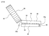
上記の目的を達成するために、本発明は、容器の胴体の上部に形成された入口を開閉するための蓋として使用されるエコキャップであって、内周面にねじ山が形成される本体と、前記本体の下部に切断可能な第1破裂部で連結される上部リングと、前記上部リングの下部に切断可能な第2破裂部で連結される下部リングとを含んでなり、前記第1破裂部は、前記本体と上部リングとが切断されて分離されないように正面に形成される折曲部を含んで構成され、前記第2破裂部は、前記上部リングと下部リングとが切断されて分離されないように背面に形成される連結部を含んで構成され、前記下部リングは、連結部の一側に第2破裂部の下部末端から下部リングの下部末端まで形成される破断溝を含んで構成されることを特徴とする、多目的エコキャップを提示する。 In order to achieve the above object, the present invention is an eco-cap used as a lid for opening and closing an inlet formed in the upper part of the body of a container, and a main body in which a thread is formed on an inner peripheral surface. An upper ring connected to the lower part of the main body by a first rupture part that can be cut, and a lower ring connected to the lower part of the upper ring by a second rupture part that can be cut. The ruptured portion includes a bent portion formed on the front surface so that the main body and the upper ring are not cut and separated, and the second ruptured portion is formed by cutting the upper ring and the lower ring. The lower ring is configured to include a connecting portion formed on the back surface so as not to be separated, and the lower ring includes a breaking groove formed on one side of the connecting portion from the lower end of the second rupture portion to the lower end of the lower ring. We present a multipurpose eco-cap, which is characterized by being composed.
また、本発明の前記折曲部は、本体の半径サイズに比べて5〜7%の長さに形成されることを特徴とし、前記連結部は、本体の半径サイズに比べて10〜14%の長さに形成されることを特徴とし、前記折曲部は、内側面に「V」字状の折曲溝が形成され、外周面には熱溶着されるホットメルトをさらに含んで構成されることを特徴とし、前記下部リングは、内周面に突設され、下面に外側方向に行くほど高さが高くなる傾斜面を有する複数の離脱防止突起をさらに含んで構成されることを特徴とする。 Further, the bent portion of the present invention is characterized in that the length is 5 to 7% of the radius size of the main body, and the connecting portion is 10 to 14% of the radius size of the main body. The bent portion is formed with a "V" -shaped bent groove on the inner side surface, and further includes hot melt to be heat-welded on the outer peripheral surface. The lower ring is characterized by further including a plurality of detachment prevention protrusions having an inclined surface that protrudes from the inner peripheral surface and has an inclined surface that increases in height toward the outside on the lower surface. And.
上述した本発明による多目的エコキャップは、入口となす角度が120度以上となるように本体が開放され、ユーザーが飲用の際に顔部分に触れないため不便さを感じない効果を得ることができ、繰り返し飲用の際に失われるおそれがないため再開閉が容易であり、資源のリサイクルのために容器から完全に分離しようとするときに容器に固定される上部リング及び下部リングが別途のツールなしで容易に分離されてリサイクルが容易であるという効果を得ることができる。 The multipurpose eco-cap according to the present invention described above has an effect that the user does not feel inconvenience because the main body is opened so that the angle formed with the entrance is 120 degrees or more and the user does not touch the face part when drinking. Easy to reopen and close as it will not be lost during repeated drinking, and the upper and lower rings fixed to the container when trying to completely separate from the container for resource recycling without additional tools The effect of being easily separated and easy to recycle can be obtained.
本発明は、内部に液体が保管される容器の入口に締結される蓋に関し、より詳細には、プラスチック、ペット樹脂、ガラス、鋼管製の容器の入口に栓として使用されるが、ユーザーが容器の内容物を飲用するとき、栓が容器と分離されないため失われるおそれがないうえ、120度以上の開放角度を維持することができるためユーザーが不便なく片手で容易に飲用することができ、容器から本体20、上部リング30及び下部リング40が容易に完全分離されることにより、容易なリサイクルを図ることができる多目的エコキャップに関する技術である。
The present invention relates to a lid fastened to the inlet of a container in which a liquid is stored, and more specifically, it is used as a stopper at the inlet of a container made of plastic, pet resin, glass, steel tube, but the user can use the container. When drinking the contents of, there is no risk of loss because the stopper is not separated from the container, and since the opening angle of 120 degrees or more can be maintained, the user can easily drink with one hand without inconvenience, and the container This is a technique related to a multipurpose eco-cap that can be easily recycled by easily completely separating the
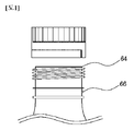
上述した本発明を達成するための構成は、容器60の胴体62の上部に形成された入口64を開閉するための蓋として使用されるエコキャップ10であって、内周面にねじ山が形成される本体20と、本体20の下部に切断可能な第1破裂部22で連結される上部リング30と、上部リング30の下部に切断可能な第2破裂部32で連結される下部リング40とを含んで構成され、前記第1破裂部22は、前記本体20と上部リング30が切断されて分離されないように正面に形成される折曲部22aを含んで構成され、前記第2破裂部32は、前記上部リング30と下部リング40が切断されて分離されないように背面に形成される連結部32aを含んで構成され、前記下部リング40は、連結部32aの一側に第2破裂部32の下部末端から下部リング40の下部末端まで形成される破断溝42を含んで構成されることを特徴とする。
The configuration for achieving the present invention described above is an eco-cap 10 used as a lid for opening and closing the
また、本発明の前記折曲部22aは、本体20の半径サイズに比べて5〜7%の長さに形成されることを特徴とし、前記連結部32aは、本体20の半径サイズに比べて10〜14%の長さに形成されることを特徴とし、前記折曲部22aは、内側面に「V」字状の折曲溝22a−1が形成され、外周面には熱融着されるホットメルト50をさらに含んで構成されることを特徴とし、前記下部リング40は、内周面に突設され、下部面に外側方向に行くほど高さが高くなる傾斜面44aを有する複数の離脱防止突起44をさらに含んで構成されることを特徴とする。
Further, the
まず、本発明を説明するに先立ち、プラスチック、ペット樹脂、ガラス、鋼管製などからなる容器60は、一般に、液体状態の内容物が保管される胴体62と、前記胴体62の上部に形成され、外周縁にねじ山(図示せず)を有する入口64とから構成される。
First, prior to explaining the present invention, the
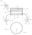
本発明は、前記容器60の胴体62の上部に形成された入口64を開閉するための蓋(栓またはキャップ)として使用される多目的エコキャップ(以下、「キャップ」という。)10であって、図1及び図2に示すように、入口64の外周縁に形成されたねじ山と対応するねじ山が内周縁に形成され、時計回りに回転すると容器60が密閉され、反対方向である反時計回りに回転すると、容器60の入口64から分離されて容器60が開放される。
The present invention is a multipurpose eco-cap (hereinafter referred to as "cap") 10 used as a lid (plug or cap) for opening and closing an
以下、本発明の実施形態を示す図1乃至図8を参照して、本発明を具体的に説明する。 Hereinafter, the present invention will be specifically described with reference to FIGS. 1 to 8 showing embodiments of the present invention.
本発明を達成するための主要構成要素である本体20は、
内周面にねじ山(図示せず)が形成されるものであって、容器60の胴体62の上部に形成された入口64のねじ山と対応するねじ山が内周面に形成され、時計回りに回転すると、入口64の下部方向に移動して密閉させ、反時計回りに回転すると、入口64の上部方向に移動して開放させる。
The
A screw thread (not shown) is formed on the inner peripheral surface, and a screw thread corresponding to the screw thread of the
このとき、本発明の本体20の外周縁には、摩擦力を高めるために、図1に示すように、複数の溝(図示せず)または突起(図示せず)が形成でき、これにより、ユーザーは容易に本体20を回転させることができる。
At this time, as shown in FIG. 1, a plurality of grooves (not shown) or protrusions (not shown) can be formed on the outer peripheral edge of the
また、本発明の本体20は、容器60の入口64を密閉させるとき、気密性を向上させるために、内側上部に嵌合される合成樹脂製の弾性力を有する密閉部材(図示せず)と、入口64の内径と同じ直径を有し、内側上部面に下方に突設される密閉突起(図示せず)とをさらに含んで構成できる。
Further, the
本発明を達成するための主要構成要素である上部リング30は、
本体20の下部に切断可能な第1破裂部22で連結されるものであって、前記第1破裂部22は、図面に全般的に示されているように、本体20と上部リング30とを飛び飛びに連結することにより、容器60の開放のために本体20がユーザーによって反時計回りに回転するとき、ねじり力が発生して破断される。
The
The first ruptured
また、前記第1破裂部22は、図3のa)と図4のa)に示すように、本体20と上部リング30が切断されて互いに完全分離されないように正面に形成される折曲部22aを含んで構成されるが、ここで、前記正面は、詳しく後述される上部リング30と連結部32aの位置を説明するための基準であって、正面方向に限定されず、第1破裂部22のいずれか一部分に形成されることは自明であろう。
Further, as shown in a) of FIG. 3 and a) of FIG. 4, the
上記と関連して、第1破裂部22は、折曲部22aによって本体20と上部リング30が互いに完全分離されることを防止することにより、ユーザーは、本体20が容器60、すなわち入口64から完全分離されず容器60の上部側面に位置することができるようにして、本体20の紛失を防止することができる効果を実現させる。
In connection with the above, the
このとき、本発明の本体20は、反時計回りに回転して入口64の上部方向に移動して入口64から完全に分離されると、前記折曲部22aによって入口64の外側へ移動するとともに、前記入口64に密閉のために結合されたときの位置である下部へ移動し、これにより、本体20の下部は入口64の外側面に係止されることにより、ユーザーが入口64に口を当てて飲用する際に本体20が口などの顔部分に触れないため不便さを感じない効果を得ることができる。
At this time, when the
すなわち、本発明の上部リング30は、本体20が反時計回りに回転すると、第1破裂部22が破断、すなわち切断されると、上部方向に一緒に移動してから、本体20が入口64から完全に分離された後、折曲部22aによって本体20と一緒に下部方向に移動して元の位置に復帰することにより、上述したような効果を実現させ、これにより前記本体20が容器60から完全に分離されないため紛失を防止することができる効果を実現させる。
That is, in the
また、前記折曲部22aは、本体20の半径サイズに比べて5〜7%の長さに形成されることを特徴とするが、これは、本体20の半径サイズに比べて5%未満の長さに形成されると、容易に破断されて本体20と上部リング30とが分離されるだけでなく、飲用の際に本体20が折曲部22aを基準に容易に回転してユーザーが不便さを感じることがある。
Further, the
また、前記折曲部22aが本体20の半径サイズに比べて7%を超える長さに形成されると、容易に破断されず、容易に回転しないために本体20の紛失の懸念及び容易な回転を防止することができるが、本体20が折曲部22aによってさらに元の位置に移動しようとする復元力が強く作用し、飲用の際にユーザーの鼻などの顔部分に触れることができるために不便さを感じてしまうので、本体20の半径サイズに比べて5〜7%の長さに形成されることが好ましい。
Further, if the
付加して説明すると、前記折曲部22aの長さは、リサイクルのために、上部リング30と後述される下部リング40を容器60から完全に分離させるために、本体20を上部方向に強く引っ張るとき、5%未満に形成されると、折曲部22aが先に破断されて上部リング30と下部リング40とが容器60の入口64の部分に残存するおそれがあるという問題点があり、本体20の半径サイズに比べて5%以上に形成されることが好ましい。
In addition, the length of the
上記と関連して、前記折曲部22aは、図5に示すように、内側面に「V」字状、より詳しくは「<」状の折曲溝22a−1が形成されることを特徴とするが、前記折曲溝22a−1は、本体20が反時計回りに回転して入口64から分離されると、図6に示すように、容易に外側方向に折れるようにする効果を実現させる。
In relation to the above, as shown in FIG. 5, the
すなわち、前記折曲溝22a−1は、折曲部22aによって本体20が再び元の位置に移動しようとする復元力を減衰させるためのものであって、入口64から分離された本体20が入口64の外側方向に容易に折れるようにして、ユーザーの飲用時に本体20が顔部分に触れるのを防止することができる。
That is, the
また、前記折曲溝22a−1が折曲部22aに形成される深さは、折曲部22aの厚さの50〜70%以下であることが好ましいが、これは、50%未満の場合には、本体20が容易に上部リング30と分離でき、70%を超える場合には、本体20が元の位置に移動しようとする復元力があまりにも増大して飲用の際にユーザーの顔に本体20が触れて不便さを感じるという問題点が発生することがあり、前記折曲溝が折曲部に形成される深さは折曲部22aの厚さの50〜70%以下であることが好ましい。
Further, the depth at which the
上記と関連して、前記折曲部22aは、図8に示すように、外周面に熱融着されるホットメルト50をさらに含んで構成できるが、前記ホットメルト50は、一般に使用されるホットメルト50を使用するが、0.5〜1mmの厚さに熱融着されて折曲部22aの強度を向上させるだけでなく、本体20が折曲部22aによって折り曲げられた、すなわち折れた状態を維持することができる効果を実現させる。
In connection with the above, the
つまり、前記ホットメルト50は、本体20が折曲部22aを基準に入口64の外側方向に折れた状態を維持するようにすることにより、飲用時にユーザーの顔に触れないようにして不便さを感じないようにし、折曲部22aの強度を向上させて、後述される上部リング30と下部リング40を容器60から完全に分離させるとき、折曲部22aが先に破断されることを防止することができるという効果が得られる。
That is, the
付加して説明すると、前記ホットメルト50が折曲部22aの外周面全体または外周面の中央部分の一部に形成されても、上述したような効果を得ることができるのは自明であり、好ましくは、図8に示すように、本体20の下部外周縁の一部と上部リング30の上部外周縁の一部まで上下、すなわち高さが形成されることが本体20と上部リング30との結合力を向上させることができる。
In addition, it is obvious that even if the
本発明を達成するための主要構成要素である下部リング40は、
上部リング30の下部に切断可能な第2破裂部32で連結されるものであって、図2に示すように、本体20が入口64に結合されているとき、入口64の下部に形成される係止溝66に位置し、図5に示すように、下部面に外側方向に行くほど高さが高くなる傾斜面44aを有する離脱防止突起44が内周面に突設され、入口64から本体20が分離されたとき、本体20と上部リング30が容器60から離脱して分離されることを防止する効果を実現させる。
The
It is connected to the lower part of the
すなわち、本発明の下部リング40は、本体20が反時計回りに回転して上部へ移動するとき、発生するねじり力によって第1破裂部22が破断され、前記第1破裂部22が破断され、一緒に回転する上部リング30に発生するねじり力によって第2破裂部32が破断された後、本体20が入口64から分離されると、内側面に突設された離脱防止突起44が係止溝66に係止されることにより、本体20と上部リング30が容器60から完全に分離されることを防止する。
That is, in the
また、前記第2破裂部32は、前記上部リング30と下部リング40とが切断されて分離されないように背面に形成される連結部32aを含んで構成されるが、前記連結部32aは、先立って説明された第1破裂部22の折曲部22aが、本体20と上部リング30が互いに完全分離されることを防止するのと同様に、上部リング30と下部リング40が互いに完全分離されることを防止することにより、ユーザーの飲用時に容器60から本体20が完全に分離されないようにして、本体20の紛失するおそれを未然に防止する効果を実現させる。
Further, the
この時、前記連結部32aは、前述した折曲部22aとは異なり折曲溝などが形成されていないように、すなわち上部リング30と下部リング40の背面の一部が一体に連結されて形成されるので、折曲部22aに比べて連結強度が強く、これによりリサイクルの際に本体20を上部方向に強く引っ張ると、下部リング40が容器60の係止溝66から離脱して本発明のキャップ10が容器60から完全分離される効果を得ることができる。
At this time, unlike the
付加して説明すると、前記連結部32aが形成される長さは、本体20の半径サイズに比べて10〜14%の長さに形成されることが好ましいが、これは、折曲部22aが本体20の半径サイズに比べて5〜7%の長さに形成されるのに比べて約2倍の差がある。
In addition, the length at which the connecting
つまり、前記連結部32aは、折曲部22aの長さより1.5〜2倍の長さに形成されることを特徴とし、これは、前記連結部32aが折曲部22aの長さよりも1.5倍未満、すなわち、本体20の半径サイズに比べて10%未満の長さに形成されると、本体20が反時計回りに回転して入口64の上部方向に移動するとき、一緒に後方が上部方向に移動する上部リング30の前面、すなわち、連結部32aを基準に入口64の外側方向に折れるようになり、上部リング30が折れることにより復元力が弱くなり、これにより入口64の上部へ移動した本体20が下部方向に復元されなくなり、ユーザーの顔に触れて不便さが発生するという問題がある。
That is, the connecting
再度説明すると、前記連結部32aは、本体20の半径サイズに比べて10%未満の長さに形成されて上部リング30を元の位置に戻るようにすると、飲用の際にユーザーの顔に本体20が触れるのを防止することができる。
To explain again, if the connecting
また、前記連結部32aが折曲部22aの長さの2倍を超える、すなわち、本体20の半径サイズに比べて14%を超える長さに形成されると、上部リング30を元の位置に移動させようとする復元力があまりにも強くて本体20を入口64から分離、すなわち、容器60を開放することが難しい問題があるので、前記連結部32aは、折曲部22aの長さよりも1.5〜2倍、すなわち、本体20の半径サイズに比べて10〜14%の長さに形成されることが好ましい。
Further, when the connecting
上記と関連して、前記連結部32aは、折曲部22aと反対の方向である背面に形成されることにより、ねじり力によって第1破裂部22と第2破裂部32とが自然に破断されるようにするとともに、リサイクルの際に本体20を上部方向に引っ張ると後述の破断溝42が容易に破断される効果を実現するようにする。
In connection with the above, the connecting
つまり、本発明の下部リング40は、連結部32aの一側に第2破裂部32の下部末端から下部リング40の下部末端まで形成される破断溝42を含んで構成され、より詳細に説明すると、前記破断溝42は、図3及び図4に示すように、第2破裂部32の末端から下部リング40の下部末端面まで、言い換えれば、下部リング40に形成されるが、第2破裂部32の一側及び他側のうちのいずれかの末端に垂直に形成される。
That is, the
また、前記破断溝42は、飲用時には下部リング40がリング形状を維持することができるようにし、リサイクル時には本体20を上部方向に引っ張ると破断され、本発明のキャップ10、すなわち本体20、上部リング30及び下部リング40が容器60から完全に分離されるようにする効果を実現させる。
Further, the breaking
この際、前記破断溝42は、下部リング40の外周縁に「V」字状に形成されることが好ましいが、これは、本体20を上部方向に引っ張ると連結部32aが上部方向及び入口42の外側方向に引っ張られるようになり、これにより下部リング40の背面、すなわち、連結部32aの下部に該当する部分が外側方向に折れることにより下部リング40の外周縁に形成されることが好ましい。
At this time, the breaking
言い換えれば、前記破断溝42は、本体20が上部へ移動するにつれて上部リング30、すなわち連結部32aが上部へ移動し、下部リング40は、離脱防止突起44によって係止溝66に係止され、これにより、連結部32aが入口64の外側方向に折れるため、破断溝が下部リング40の内周縁に形成されると、破断溝42が破断されずに曲がることができるが、破断溝が下部リング40の外周縁に形成されると、破断溝42が曲がると同時に破断されるのである。
In other words, in the breaking
上記と関連して、本発明の下部リング40の内周面に突設される複数の離脱防止突起44は、図5に示すように、下部面に外側方向に、すなわち、入口64の外側方向に行くほど高さが高くなる傾斜面44aが形成されることにより、破断溝42が破断されなかったとき、離脱防止突起44が傾斜面44aによって下部方向に曲がって係止溝66から離脱してエコキャップ10を容器60から完全に分離することができる。
In connection with the above, the plurality of
総合して説明すると、本発明のエコキャップ10は、本体20を反時計回りに回転させて第1破裂部22にねじり力を加えると、上部リング30もねじり力が作用して第2破裂部32にねじり力が加わるようになり、これにより第1、2破裂部22、32が破断されて本体20が入口64から分離されると、本体20は折曲部22aとホットメルト50によって折り曲げられた状態を維持することにより、ユーザーの飲用時に本体20が顔部分に触れる不便さを解消することができる。
Overall, in the
また、本発明のキャップ10の折曲部22aは、折曲溝22a−1とホットメルト50によって本体20を入口64の外側方向に自然に曲がるようにするだけでなく、強度を向上させることで繰り返す動きにより破断するのを防止することができ、下部リング40の破断溝42を破断させるために本体20を上部に引っ張るときにも破断溝42より先に破断するのを防止することができる。
Further, the
また、本発明の下部リング40の離脱防止突起44は、破断溝42の不良により、本体20を引っ張っても破断溝42が破断されない場合、係止溝66に係止されて自然に下部方向に曲がることができるようにすることにより、キャップ10が容器60から完全に分離できるようにする効果を得ることができる。
Further, if the
特に、本発明は、本出願人が先出願した韓国公開実用新案第2015−0001931号とは異なり、上部リング30が破断されないようにすることにより、本体20がさらに安定的に入口64の外側に固定された状態を維持することができるようにして、ユーザーの飲用時に不便さを最小限に抑えた。
In particular, in the present invention, unlike the Korean public utility model No. 2015-0001931 filed earlier by the applicant, the
以上、本発明の好適な実施形態を参照して説明したが、本発明は、これらの実施形態に限定されず、本発明の属する技術分野における通常の知識を有する者が、本発明の要旨を逸脱することなく、様々な変更を加えて実施することができる。
Although the above description has been made with reference to the preferred embodiments of the present invention, the present invention is not limited to these embodiments, and a person having ordinary knowledge in the technical field to which the present invention belongs can give the gist of the present invention. It can be implemented with various changes without deviation.
Claims (6)
内周面にねじ山が形成される本体(20)と、
前記本体(20)の下部に切断可能な第1破裂部(22)で連結される破断不能な環状をなす上部リング(30)と、
前記上部リング(30)の下部に切断可能な第2破裂部(32)で連結される下部リング(40)とを含んでなり、
前記第1破裂部(22)は、
前記本体(20)と前記上部リング(30)が切断されて分離されないように正面に形成される折曲部(22a)を含んで構成され、
前記第2破裂部(32)は、
前記上部リング(30)と下部リング(40)が切断されて分離されないように背面に形成される連結部(32a)を含んで構成され、
前記下部リング(40)は、
連結部(32a)の一側に第2破裂部(32)の下部末端から下部リング(40)の下部末端まで形成される破断溝(42)を含んで構成され、
前記連結部(32a)の上部方向に加わる力に対する連結強度は、前記折曲部(22a)よりも高く設定され、
前記折曲部(22a)の上部方向に加わる力に対する連結強度は、前記下部リング(40)の前記破断溝(42)に対応する部分よりも高く設定されていることを特徴とする、多目的エコキャップ。 A multipurpose eco-cap (10) used as a lid for opening and closing the inlet (64) formed on the upper part of the body (62) of the container (60).
The main body (20) with threads formed on the inner peripheral surface,
An inbreakable annular upper ring (30) connected to the lower part of the main body (20) by a cuttable first rupture portion (22).
The lower part of the upper ring (30) includes a lower ring (40) connected by a cuttable second rupture part (32).
The first rupture portion (22) is
It is configured to include a bent portion (22a) formed on the front surface so that the main body (20) and the upper ring (30) are not cut and separated.
The second rupture portion (32) is
It is configured to include a connecting portion (32a) formed on the back surface so that the upper ring (30) and the lower ring (40) are not cut and separated.
The lower ring (40)
It is configured to include a breaking groove (42) formed from the lower end of the second rupture portion (32) to the lower end of the lower ring (40) on one side of the connecting portion (32a) .
The connecting strength with respect to the force applied in the upper direction of the connecting portion (32a) is set higher than that of the bent portion (22a).
Coupling strength against a force applied to the upper direction of the bent portion (22a) is characterized that you have been set higher than the rupture groove (42) corresponding to the portion of the lower ring (40), multi-purpose Eco cap.
前記折曲部(22a)の上部方向に加わる力に対する連結強度は、前記離脱防止突起(44)の傾斜面(44a)に対応する部分よりも高く設定されていることを特徴とする、請求項1に記載の多目的エコキャップ。 It said lower ring (40) is protruded from the inner circumferential surface, a plurality of removal prevention protrusion having a lower ring (40) inclined surface go higher height in the radial direction outer side is higher in the lower surface (44a) ( further look at including the 44),
Coupling strength against a force applied to the upper direction of the bent portion (22a) is characterized that you have been set higher than the inclined surface portion corresponding to (44a) of the removal prevention protrusion (44), according to claim The multipurpose eco-cap described in 1.
Applications Claiming Priority (3)
| Application Number | Priority Date | Filing Date | Title |
|---|---|---|---|
| KR10-2016-0151188 | 2016-11-14 | ||
| KR1020160151188A KR101744846B1 (en) | 2016-11-14 | 2016-11-14 | Eco-friendly multi-purpose cap |
| PCT/KR2017/011813 WO2018088723A1 (en) | 2016-11-14 | 2017-10-25 | Multipurpose eco-friendly cap |
Publications (2)
| Publication Number | Publication Date |
|---|---|
| JP2019534218A JP2019534218A (en) | 2019-11-28 |
| JP6793263B2 true JP6793263B2 (en) | 2020-12-02 |
Family
ID=59220879
Family Applications (1)
| Application Number | Title | Priority Date | Filing Date |
|---|---|---|---|
| JP2019547052A Active JP6793263B2 (en) | 2016-11-14 | 2017-10-25 | Multipurpose eco cap |
Country Status (4)
| Country | Link |
|---|---|
| JP (1) | JP6793263B2 (en) |
| KR (1) | KR101744846B1 (en) |
| BR (1) | BR112019009683B1 (en) |
| WO (1) | WO2018088723A1 (en) |
Families Citing this family (10)
| Publication number | Priority date | Publication date | Assignee | Title |
|---|---|---|---|---|
| WO2019100015A1 (en) * | 2017-11-18 | 2019-05-23 | Phillip John Campbell | Closure with tether docking |
| WO2019177616A1 (en) * | 2018-03-15 | 2019-09-19 | Bericap Inc. | Tethered container closure |
| US10836544B2 (en) | 2018-05-09 | 2020-11-17 | Silgan White Cap LLC | Closure with hinge |
| KR101956185B1 (en) * | 2018-08-08 | 2019-03-08 | 김현태 | Bottle cap |
| BR112021007456A2 (en) | 2018-11-16 | 2021-07-20 | Bericap Holding Gmbh | screw cap, closure comprising it and combination comprising a bottle neck with a male thread and a closure |
| CN212797893U (en) | 2019-05-13 | 2021-03-26 | 赫斯基注塑系统有限公司 | Closure device for a container and mould for forming a closure device by injection moulding |
| KR102258555B1 (en) | 2019-08-08 | 2021-05-28 | 양복주 | Eco-friendly bottle cap with improved usability |
| US20230356901A1 (en) | 2020-09-23 | 2023-11-09 | Sacmi Cooperativa Meccanici Imola Societa’ Cooperativa | Cap for container |
| KR102457685B1 (en) * | 2021-10-14 | 2022-10-24 | 양복주 | Eco-friendly cap with detachable and completely detachable structure |
| WO2023085513A1 (en) * | 2021-11-10 | 2023-05-19 | 박준효 | Beverage bottle cap |
Family Cites Families (5)
| Publication number | Priority date | Publication date | Assignee | Title |
|---|---|---|---|---|
| KR200213792Y1 (en) * | 2000-09-07 | 2001-02-15 | 주식회사대산금속 | A bottle cap |
| KR100855087B1 (en) * | 2007-10-15 | 2008-08-29 | (주)베스트이지캡 | A container with anti-idle stopper |
| KR100997319B1 (en) * | 2010-01-25 | 2010-11-29 | 권시중 | A container with anti-missing and anti-idle stopper |
| KR101325850B1 (en) * | 2013-06-09 | 2013-11-05 | 권시중 | Container cap |
| KR20150001931U (en) * | 2015-04-10 | 2015-05-20 | 양복주 | Eco cap for containers |
-
2016
- 2016-11-14 KR KR1020160151188A patent/KR101744846B1/en active IP Right Grant
-
2017
- 2017-10-25 JP JP2019547052A patent/JP6793263B2/en active Active
- 2017-10-25 WO PCT/KR2017/011813 patent/WO2018088723A1/en active Application Filing
- 2017-10-25 BR BR112019009683-3A patent/BR112019009683B1/en active IP Right Grant
Also Published As
| Publication number | Publication date |
|---|---|
| KR101744846B1 (en) | 2017-06-08 |
| BR112019009683A2 (en) | 2019-08-06 |
| BR112019009683B1 (en) | 2023-01-31 |
| WO2018088723A1 (en) | 2018-05-17 |
| JP2019534218A (en) | 2019-11-28 |
Similar Documents
| Publication | Publication Date | Title |
|---|---|---|
| JP6793263B2 (en) | Multipurpose eco cap | |
| JP6921959B2 (en) | Container stopper for easy separation and recovery | |
| JP6282354B2 (en) | Improved tamper evident cover | |
| JP2010537899A (en) | Closures for bottles and assembly of such closures and bottles | |
| JP2015081092A (en) | Hinge cap | |
| WO2010150597A1 (en) | Structure for removing end-ring of resin bottle cap, and container provided with the same | |
| TW201704106A (en) | A container cap with function of anti-missing and anti-idle stopper | |
| US9828148B2 (en) | Container with a securing device | |
| JP3870226B2 (en) | Bottle cap closure structure | |
| KR102177076B1 (en) | Cap for pet-containers in which end ring are simultaneously separated | |
| JP6124783B2 (en) | Separation cap | |
| JP6835515B2 (en) | Container sealing device | |
| JP6598655B2 (en) | Hinge cap | |
| JP4531516B2 (en) | Container lid | |
| JP4795104B2 (en) | cap | |
| KR102258555B1 (en) | Eco-friendly bottle cap with improved usability | |
| JP7246831B2 (en) | pouring cap | |
| JP2009001333A (en) | Recycle encouraging liquid container with stopper cap opening/closing function and stopper cap | |
| JP7118724B2 (en) | cap with inner plug | |
| JP7060346B2 (en) | Composite cap | |
| JP6363036B2 (en) | Stopper cap | |
| US20220153467A1 (en) | Pet container cap with simultaneously separable end ring | |
| JP2007131327A (en) | Hinge cap | |
| TWI613130B (en) | Clamshell one-piece filter cover | |
| KR20020075761A (en) | Spout |
Legal Events
| Date | Code | Title | Description |
|---|---|---|---|
| A621 | Written request for application examination |
Free format text: JAPANESE INTERMEDIATE CODE: A621 Effective date: 20190510 |
|
| A977 | Report on retrieval |
Free format text: JAPANESE INTERMEDIATE CODE: A971007 Effective date: 20200520 |
|
| A131 | Notification of reasons for refusal |
Free format text: JAPANESE INTERMEDIATE CODE: A131 Effective date: 20200602 |
|
| A521 | Request for written amendment filed |
Free format text: JAPANESE INTERMEDIATE CODE: A523 Effective date: 20200828 |
|
| TRDD | Decision of grant or rejection written | ||
| A01 | Written decision to grant a patent or to grant a registration (utility model) |
Free format text: JAPANESE INTERMEDIATE CODE: A01 Effective date: 20201104 |
|
| A61 | First payment of annual fees (during grant procedure) |
Free format text: JAPANESE INTERMEDIATE CODE: A61 Effective date: 20201109 |
|
| R150 | Certificate of patent or registration of utility model |
Ref document number: 6793263 Country of ref document: JP Free format text: JAPANESE INTERMEDIATE CODE: R150 |
|
| R250 | Receipt of annual fees |
Free format text: JAPANESE INTERMEDIATE CODE: R250 |