JP6789889B2 - Sample processing equipment - Google Patents

Sample processing equipment Download PDF

Info

Publication number
JP6789889B2
JP6789889B2 JP2017123833A JP2017123833A JP6789889B2 JP 6789889 B2 JP6789889 B2 JP 6789889B2 JP 2017123833 A JP2017123833 A JP 2017123833A JP 2017123833 A JP2017123833 A JP 2017123833A JP 6789889 B2 JP6789889 B2 JP 6789889B2
Authority
JP
Japan
Prior art keywords
sample
air
recess
groove
flow
Prior art date
Legal status (The legal status is an assumption and is not a legal conclusion. Google has not performed a legal analysis and makes no representation as to the accuracy of the status listed.)
Active
Application number
JP2017123833A
Other languages
Japanese (ja)
Other versions
JP2019007841A5 (en
JP2019007841A (en
Inventor
長岡 嘉浩
嘉浩 長岡
基博 山崎
基博 山崎
Current Assignee (The listed assignees may be inaccurate. Google has not performed a legal analysis and makes no representation or warranty as to the accuracy of the list.)
Hitachi High Tech Corp
Original Assignee
Hitachi High Tech Corp
Priority date (The priority date is an assumption and is not a legal conclusion. Google has not performed a legal analysis and makes no representation as to the accuracy of the date listed.)
Filing date
Publication date
Priority to JP2017123833A priority Critical patent/JP6789889B2/en
Application filed by Hitachi High Tech Corp filed Critical Hitachi High Tech Corp
Priority to PCT/JP2018/018259 priority patent/WO2019003659A1/en
Priority to CN201880032745.2A priority patent/CN110637233A/en
Priority to US16/609,248 priority patent/US20200047181A1/en
Priority to DE112018001977.2T priority patent/DE112018001977T5/en
Priority to GB1915791.6A priority patent/GB2577406B/en
Priority to SG11201910270XA priority patent/SG11201910270XA/en
Publication of JP2019007841A publication Critical patent/JP2019007841A/en
Publication of JP2019007841A5 publication Critical patent/JP2019007841A5/ja
Application granted granted Critical
Publication of JP6789889B2 publication Critical patent/JP6789889B2/en
Active legal-status Critical Current
Anticipated expiration legal-status Critical

Links

Images

Classifications

    • BPERFORMING OPERATIONS; TRANSPORTING
    • B01PHYSICAL OR CHEMICAL PROCESSES OR APPARATUS IN GENERAL
    • B01LCHEMICAL OR PHYSICAL LABORATORY APPARATUS FOR GENERAL USE
    • B01L3/00Containers or dishes for laboratory use, e.g. laboratory glassware; Droppers
    • B01L3/50Containers for the purpose of retaining a material to be analysed, e.g. test tubes
    • B01L3/502Containers for the purpose of retaining a material to be analysed, e.g. test tubes with fluid transport, e.g. in multi-compartment structures
    • B01L3/5027Containers for the purpose of retaining a material to be analysed, e.g. test tubes with fluid transport, e.g. in multi-compartment structures by integrated microfluidic structures, i.e. dimensions of channels and chambers are such that surface tension forces are important, e.g. lab-on-a-chip
    • B01L3/502715Containers for the purpose of retaining a material to be analysed, e.g. test tubes with fluid transport, e.g. in multi-compartment structures by integrated microfluidic structures, i.e. dimensions of channels and chambers are such that surface tension forces are important, e.g. lab-on-a-chip characterised by interfacing components, e.g. fluidic, electrical, optical or mechanical interfaces
    • BPERFORMING OPERATIONS; TRANSPORTING
    • B01PHYSICAL OR CHEMICAL PROCESSES OR APPARATUS IN GENERAL
    • B01LCHEMICAL OR PHYSICAL LABORATORY APPARATUS FOR GENERAL USE
    • B01L3/00Containers or dishes for laboratory use, e.g. laboratory glassware; Droppers
    • B01L3/50Containers for the purpose of retaining a material to be analysed, e.g. test tubes
    • B01L3/502Containers for the purpose of retaining a material to be analysed, e.g. test tubes with fluid transport, e.g. in multi-compartment structures
    • B01L3/5027Containers for the purpose of retaining a material to be analysed, e.g. test tubes with fluid transport, e.g. in multi-compartment structures by integrated microfluidic structures, i.e. dimensions of channels and chambers are such that surface tension forces are important, e.g. lab-on-a-chip
    • B01L3/502738Containers for the purpose of retaining a material to be analysed, e.g. test tubes with fluid transport, e.g. in multi-compartment structures by integrated microfluidic structures, i.e. dimensions of channels and chambers are such that surface tension forces are important, e.g. lab-on-a-chip characterised by integrated valves
    • BPERFORMING OPERATIONS; TRANSPORTING
    • B81MICROSTRUCTURAL TECHNOLOGY
    • B81BMICROSTRUCTURAL DEVICES OR SYSTEMS, e.g. MICROMECHANICAL DEVICES
    • B81B3/00Devices comprising flexible or deformable elements, e.g. comprising elastic tongues or membranes
    • GPHYSICS
    • G01MEASURING; TESTING
    • G01NINVESTIGATING OR ANALYSING MATERIALS BY DETERMINING THEIR CHEMICAL OR PHYSICAL PROPERTIES
    • G01N35/00Automatic analysis not limited to methods or materials provided for in any single one of groups G01N1/00 - G01N33/00; Handling materials therefor
    • G01N35/02Automatic analysis not limited to methods or materials provided for in any single one of groups G01N1/00 - G01N33/00; Handling materials therefor using a plurality of sample containers moved by a conveyor system past one or more treatment or analysis stations
    • GPHYSICS
    • G01MEASURING; TESTING
    • G01NINVESTIGATING OR ANALYSING MATERIALS BY DETERMINING THEIR CHEMICAL OR PHYSICAL PROPERTIES
    • G01N35/00Automatic analysis not limited to methods or materials provided for in any single one of groups G01N1/00 - G01N33/00; Handling materials therefor
    • G01N35/08Automatic analysis not limited to methods or materials provided for in any single one of groups G01N1/00 - G01N33/00; Handling materials therefor using a stream of discrete samples flowing along a tube system, e.g. flow injection analysis
    • GPHYSICS
    • G01MEASURING; TESTING
    • G01NINVESTIGATING OR ANALYSING MATERIALS BY DETERMINING THEIR CHEMICAL OR PHYSICAL PROPERTIES
    • G01N37/00Details not covered by any other group of this subclass
    • BPERFORMING OPERATIONS; TRANSPORTING
    • B01PHYSICAL OR CHEMICAL PROCESSES OR APPARATUS IN GENERAL
    • B01LCHEMICAL OR PHYSICAL LABORATORY APPARATUS FOR GENERAL USE
    • B01L2200/00Solutions for specific problems relating to chemical or physical laboratory apparatus
    • B01L2200/06Fluid handling related problems
    • B01L2200/0605Metering of fluids
    • BPERFORMING OPERATIONS; TRANSPORTING
    • B01PHYSICAL OR CHEMICAL PROCESSES OR APPARATUS IN GENERAL
    • B01LCHEMICAL OR PHYSICAL LABORATORY APPARATUS FOR GENERAL USE
    • B01L2200/00Solutions for specific problems relating to chemical or physical laboratory apparatus
    • B01L2200/06Fluid handling related problems
    • B01L2200/0684Venting, avoiding backpressure, avoid gas bubbles
    • BPERFORMING OPERATIONS; TRANSPORTING
    • B01PHYSICAL OR CHEMICAL PROCESSES OR APPARATUS IN GENERAL
    • B01LCHEMICAL OR PHYSICAL LABORATORY APPARATUS FOR GENERAL USE
    • B01L2300/00Additional constructional details
    • B01L2300/08Geometry, shape and general structure
    • B01L2300/0809Geometry, shape and general structure rectangular shaped
    • B01L2300/0816Cards, e.g. flat sample carriers usually with flow in two horizontal directions
    • BPERFORMING OPERATIONS; TRANSPORTING
    • B01PHYSICAL OR CHEMICAL PROCESSES OR APPARATUS IN GENERAL
    • B01LCHEMICAL OR PHYSICAL LABORATORY APPARATUS FOR GENERAL USE
    • B01L2300/00Additional constructional details
    • B01L2300/08Geometry, shape and general structure
    • B01L2300/0861Configuration of multiple channels and/or chambers in a single devices
    • B01L2300/0874Three dimensional network
    • BPERFORMING OPERATIONS; TRANSPORTING
    • B01PHYSICAL OR CHEMICAL PROCESSES OR APPARATUS IN GENERAL
    • B01LCHEMICAL OR PHYSICAL LABORATORY APPARATUS FOR GENERAL USE
    • B01L2300/00Additional constructional details
    • B01L2300/12Specific details about materials
    • B01L2300/123Flexible; Elastomeric
    • GPHYSICS
    • G01MEASURING; TESTING
    • G01NINVESTIGATING OR ANALYSING MATERIALS BY DETERMINING THEIR CHEMICAL OR PHYSICAL PROPERTIES
    • G01N35/00Automatic analysis not limited to methods or materials provided for in any single one of groups G01N1/00 - G01N33/00; Handling materials therefor
    • G01N35/02Automatic analysis not limited to methods or materials provided for in any single one of groups G01N1/00 - G01N33/00; Handling materials therefor using a plurality of sample containers moved by a conveyor system past one or more treatment or analysis stations
    • G01N35/04Details of the conveyor system
    • G01N2035/0474Details of actuating means for conveyors or pipettes
    • G01N2035/0479Details of actuating means for conveyors or pipettes hydraulic or pneumatic

Landscapes

  • Chemical & Material Sciences (AREA)
  • Health & Medical Sciences (AREA)
  • Analytical Chemistry (AREA)
  • General Health & Medical Sciences (AREA)
  • Immunology (AREA)
  • Biochemistry (AREA)
  • Life Sciences & Earth Sciences (AREA)
  • General Physics & Mathematics (AREA)
  • Physics & Mathematics (AREA)
  • Pathology (AREA)
  • Hematology (AREA)
  • Dispersion Chemistry (AREA)
  • Clinical Laboratory Science (AREA)
  • Chemical Kinetics & Catalysis (AREA)
  • Computer Hardware Design (AREA)
  • Microelectronics & Electronic Packaging (AREA)
  • Engineering & Computer Science (AREA)
  • Automatic Analysis And Handling Materials Therefor (AREA)
  • Micromachines (AREA)

Description

本発明は,試料処理装置に関する。 The present invention relates to a sample processing apparatus.

マイクロ流動システムおよび方法が特許文献1に記載されている。この特許文献には,「マイクロ流動システムは,剛体層と,弾性体層と,剛体層および弾性体層の間の流体室あるいは流路と,流体室あるいは流路の流体を操作するための弾性体層を変形させる制御手段を備える。」と記載されている。 A microfluidic system and method are described in Patent Document 1. In this patent document, "a microfluidic system is a rigid body layer, an elastic body layer, a fluid chamber or flow path between a rigid body layer and an elastic body layer, and elasticity for manipulating the fluid in the fluid chamber or flow path. It is provided with a control means for deforming the body layer. "

WO2010/073020WO2010 / 073020

前記特許文献1には,流体室あるいは流路の流体を操作するための弾性体層を変形させる制御手段を備えたマイクロ流動システムが記載されている。しかし,特許文献1に記載されたマイクロ流動システムは,弾性体層の変形を繰り返すことで所定の体積流量,すなわち単位時間当たりに流す流体の所定の体積,を実現しているが,一定量の流体を定量する操作については記載がない。このため,流体の一部を一定量取り出して処理する操作,たとえば,2種類の流体を一定の体積比率で混合させる操作では,十分な精度の体積比率を実現できない問題があった。 Patent Document 1 describes a microfluidic system including a control means for deforming an elastic layer for manipulating a fluid in a fluid chamber or a flow path. However, the microfluidic system described in Patent Document 1 realizes a predetermined volumetric flow rate, that is, a predetermined volume of the fluid flowing per unit time by repeating the deformation of the elastic layer, but a certain amount. There is no description about the operation to quantify the fluid. For this reason, there is a problem that a volume ratio with sufficient accuracy cannot be realized by an operation of taking out a certain amount of a fluid and processing it, for example, an operation of mixing two kinds of fluids at a constant volume ratio.

本発明の目的は,弾性膜の変形により流体の定量ができるようにした試料処理装置を提供することにある。 An object of the present invention is to provide a sample processing apparatus capable of quantifying a fluid by deforming an elastic membrane.

上記課題を解決するために,代表的な本発明の試料処理装置の一つは,
下面側に流路を有する分析チップ、上面側に複数の凹部を有する駆動部、分析チップと駆動部の間に位置する弾性膜、弾性膜が分析チップ側へ密着するか駆動部側へ密着するかを切り替える空気圧制御部を備えた試料処理装置であって、
分析チップは、液体の定量のための定量流路と、当該定量流路から分岐した少なくとも4つの分岐流路を備え、
駆動部は、4つの分岐流路における定量流路側でない端部のそれぞれの下方に凹部を有し、
それぞれの凹部は前記空気圧制御部に連通していることにより達成される。
In order to solve the above problems, one of the typical sample processing devices of the present invention is
An analysis chip having a flow path on the lower surface side, a drive unit having a plurality of recesses on the upper surface side, an elastic film located between the analysis chip and the drive unit, and an elastic film adhered to the analysis chip side or to the drive unit side. It is a sample processing device equipped with an air pressure control unit that switches between
The analysis chip includes a quantification channel for quantifying the liquid and at least four branch channels branched from the quantification channel.
The drive unit has recesses below each of the ends of the four branch channels that are not on the metering channel side.
Each recess is achieved by communicating with the pneumatic control unit.

本発明によれば,弾性膜の変形により流体の定量ができるようにした試料処理装置を提供することができる。 According to the present invention, it is possible to provide a sample processing apparatus capable of quantifying a fluid by deforming an elastic membrane.

上記した以外の課題,構成及び効果は,以下の実施形態の説明により明らかにされる。 Issues, configurations and effects other than those described above will be clarified by the following description of the embodiments.

実施例1に係る分析チップの上面図及び側面断面図。Top view and side sectional view of the analysis chip according to the first embodiment. 実施例1に係る試料処理装置の上面図及び側面図。Top view and side view of the sample processing apparatus according to the first embodiment. 実施例1に係る試料処理装置の駆動部の圧力を制御するための空気配管系統図。The air piping system diagram for controlling the pressure of the drive part of the sample processing apparatus which concerns on Example 1. FIG. 実施例1に係る試料処理装置の操作フローを示す図。The figure which shows the operation flow of the sample processing apparatus which concerns on Example 1. FIG. 実施例1に係る試料処理装置の分析動作フローを示す図。The figure which shows the analysis operation flow of the sample processing apparatus which concerns on Example 1. FIG. 実施例1に係る試料処理装置の試料導入動作フローを示す図。The figure which shows the sample introduction operation flow of the sample processing apparatus which concerns on Example 1. FIG. 実施例1に係る試料処理装置の試料導入動作の説明図。The explanatory view of the sample introduction operation of the sample processing apparatus which concerns on Example 1. FIG. 実施例1に係る試料処理装置の試料導入動作の説明図。The explanatory view of the sample introduction operation of the sample processing apparatus which concerns on Example 1. FIG. 実施例1に係る試料処理装置の試料の保持状態を示す説明図。The explanatory view which shows the holding state of the sample of the sample processing apparatus which concerns on Example 1. FIG. 実施例1に係る試料処理装置の試料廃棄動作フローを示す図。The figure which shows the sample disposal operation flow of the sample processing apparatus which concerns on Example 1. FIG. 実施例1に係る試料処理装置の試料廃棄動作の説明図。The explanatory view of the sample disposal operation of the sample processing apparatus which concerns on Example 1. FIG. 実施例1に係る試料処理装置の試料廃棄動作の説明図。The explanatory view of the sample disposal operation of the sample processing apparatus which concerns on Example 1. FIG. 実施例1に係る試料処理装置の試料切り出し動作フローを示す図。The figure which shows the sample cutting operation flow of the sample processing apparatus which concerns on Example 1. FIG. 実施例1に係る試料処理装置の試料切り出し動作の説明図。The explanatory view of the sample cutting operation of the sample processing apparatus which concerns on Example 1. FIG. 実施例1に係る試料処理装置の試料切り出し動作の説明図。The explanatory view of the sample cutting operation of the sample processing apparatus which concerns on Example 1. FIG. 実施例1に係る試料処理装置の試薬導入動作フローを示す図。The figure which shows the reagent introduction operation flow of the sample processing apparatus which concerns on Example 1. FIG. 実施例1に係る試料処理装置の攪拌動作フローを示す図。The figure which shows the stirring operation flow of the sample processing apparatus which concerns on Example 1. FIG. 実施例1に係る試料処理装置の攪拌動作の説明図。The explanatory view of the stirring operation of the sample processing apparatus which concerns on Example 1. FIG. 実施例1に係る試料処理装置の攪拌動作の説明図。The explanatory view of the stirring operation of the sample processing apparatus which concerns on Example 1. FIG. 実施例1に係る試料処理装置の計測動作フローを示す図。The figure which shows the measurement operation flow of the sample processing apparatus which concerns on Example 1. FIG. 実施例2に係る分析チップの上面図及び側面断面図。Top view and side sectional view of the analysis chip according to the second embodiment. 実施例3に係る分析チップの上面図及び側面断面図。Top view and side sectional view of the analysis chip according to the third embodiment.

以下,実施例を図面を用いて説明する。 Hereinafter, examples will be described with reference to the drawings.

以下,実施例1に係る試料処理装置を図1−図3を用いて説明する。本実施例では,試料処理装置内で,血液,尿,スワブ等の液状化したものなどの試料と試薬を流動させて一定の体積比率で混合し,化学物質の同定および定量などの光学計測を行うための試料処理装置を説明する。 Hereinafter, the sample processing apparatus according to the first embodiment will be described with reference to FIGS. 1 to 3. In this example, a sample such as liquefied blood, urine, swab, etc. and a reagent are flowed and mixed in a constant volume ratio in a sample processing device, and optical measurement such as identification and quantification of chemical substances is performed. The sample processing apparatus for carrying out will be described.

図2の(A),(B)は,実施例1に係る試料処理装置の上面図,側面図を示す。同図の試料処理装置では,分析チップ10及びメンブレン20が,蓋30により駆動部40に押し付けられている。蓋30は回転支持部31を中心に回転可能に支持されており,図2の(A)では蓋30は開きかけの状態を示しており,2つの分析チップ10が並置されている。図2の(B)では蓋30は完全に閉じて,ロック機構51で筺体50に対して締め付けられている。蓋30には,試料や試薬を分析チップ10に投入するための試料投入窓32および試薬投入窓33,分析結果を観測するための観測窓34が設けられている。 (A) and (B) of FIG. 2 show a top view and a side view of the sample processing apparatus according to the first embodiment. In the sample processing apparatus shown in the figure, the analysis chip 10 and the membrane 20 are pressed against the drive unit 40 by the lid 30. The lid 30 is rotatably supported around the rotation support portion 31, and in FIG. 2A, the lid 30 is in a state of being opened, and two analysis chips 10 are juxtaposed. In FIG. 2B, the lid 30 is completely closed and is fastened to the housing 50 by the lock mechanism 51. The lid 30 is provided with a sample charging window 32 and a reagent charging window 33 for charging a sample or a reagent into the analysis chip 10, and an observation window 34 for observing the analysis result.

筺体50の下には,駆動部40内の空気圧を制御するための制御部60を設け,空気配管70が駆動部40から制御部60に繋がっている。制御部60の動作は,装置外部の操作部61からの信号により制御される。 A control unit 60 for controlling the air pressure in the drive unit 40 is provided under the housing 50, and an air pipe 70 is connected from the drive unit 40 to the control unit 60. The operation of the control unit 60 is controlled by a signal from the operation unit 61 outside the apparatus.

図1の(A),(B),(C)は,実施例1に係る分析チップが,メンブレンを介して,駆動部に密着している状態の上面図,側面断面図(AA断面),側面断面図(BB断面)である。図1では,分析チップ10が図2の試料処理装置に装着され,蓋30により,メンブレン20を介して,駆動部40が押し付けられている状態を示している。図1の(A)は分析チップ10の上面側から見た図で,分析チップ上面側の容器としてのウエルは実線で,分析チップ下面側の溝及び駆動部40の凹みは破線で示している。図1の(B)は,図1(A)のAA断面,図1の(C)は,図1(A)のBB断面で,分析チップ10と駆動部40がメンブレン20を介して接触している。 1 (A), (B), and (C) of FIG. 1 are a top view, a side sectional view (AA cross section), in which the analysis chip according to the first embodiment is in close contact with the drive unit via a membrane. It is a side sectional view (BB sectional view). FIG. 1 shows a state in which the analysis chip 10 is attached to the sample processing apparatus of FIG. 2 and the driving unit 40 is pressed by the lid 30 via the membrane 20. FIG. 1A is a view seen from the upper surface side of the analysis chip 10, the well as a container on the upper surface side of the analysis chip is shown by a solid line, and the groove on the lower surface side of the analysis chip and the recess of the drive unit 40 are shown by a broken line. .. 1 (B) is an AA cross section of FIG. 1 (A), and FIG. 1 (C) is a BB cross section of FIG. 1 (A). The analysis chip 10 and the driving unit 40 are in contact with each other via the membrane 20. ing.

分析チップ10の上面側には,容器としての試料用ウエル11,空気とり込み用ウエル12,試料廃棄用ウエル13,攪拌用ウエル14,試薬用ウエル15,混合液廃棄用ウエル16を設けており,下面側には,複数の溝111,112,113,114,115,121,122,123,124,131,132,133,141,142,143,144,145,151,152,153,154,161,162,163,164,165を設けている。 On the upper surface side of the analysis chip 10, a sample well 11 as a container, an air intake well 12, a sample disposal well 13, a stirring well 14, a reagent well 15, and a mixed solution disposal well 16 are provided. , Multiple grooves 111, 112, 113, 114, 115, 121, 122, 123, 124, 131, 132, 133, 141, 142, 143, 144, 145, 151, 152, 153, 154 on the lower surface side. , 161, 162,163,164,165 are provided.

メンブレン20は,ゴムや樹脂などの高分子化合物からなる弾性体で,空気圧で変形することにより流体を移動させるとともに,分析チップ10と駆動部40それぞれの表面に密着することで,流体を封止している。 The membrane 20 is an elastic body made of a polymer compound such as rubber or resin, and moves the fluid by being deformed by air pressure, and seals the fluid by adhering to the surfaces of the analysis chip 10 and the drive unit 40. doing.

駆動部40は,メンブレン20に密着する上面側に凹み41,42,43,44,45,46,47,48,49,4A,4B,4C,4D,4E,4Fを設け,各凹みから2種類の管,すなわち加圧管411,421,431,441,451,461,471,481,491,4A1,4B1,4C1,4D1,4E1,4F1,及び減圧管412,422,432,442,452,462,472,482,492,4A2,4B2,4C2,4D2,4E2,4F2それぞれが,図2に示した空気配管70に接続されている。 The drive unit 40 is provided with recesses 41, 42, 43, 44, 45, 46, 47, 48, 49, 4A, 4B, 4C, 4D, 4E, 4F on the upper surface side in close contact with the membrane 20, and 2 from each recess. Types of tubes, ie pressurizing tubes 411,421,431,441,451,461,471,481,491,4A1,4B1,4C1,4D1,4E1,4F1, and decompression tubes 421,422,432,442,452 462,472,482,492,4A2,4B2,4C2,4D2,4E2,4F2, respectively, are connected to the air pipe 70 shown in FIG.

図3は,本実施例の駆動部40の圧力を制御するための空気配管系統図であり,制御部60内に設置されている。加圧用ポンプ71から15系統に分岐し,加圧用電磁弁711,721,731,741,751,761,771,781,791,7A1,7B1,7C1,7D1,7E1,7F1を経てさらに2系統に分岐し,駆動部40の加圧管に接続している。加圧用電磁弁から2系統に分岐しているのは,本実施例の試料処理装置が図2の(A)に示したように2つの分析チップを搭載しているためである。同様に,減圧用ポンプ72から15系統に分岐し,減圧用電磁弁712,722,732,742,752,762,772,782,792,7A2,7B2,7C2,7D2,7E2,7F2を経てさらに2系統に分岐し,駆動部40の減圧管に接続している。 FIG. 3 is an air piping system diagram for controlling the pressure of the drive unit 40 of this embodiment, and is installed in the control unit 60. Branches from the pressurizing pump 71 to 15 systems, and further becomes 2 systems via the pressurizing solenoid valves 711,721,731,741,751,761,771,781,791,7A1,7B1,7C1,7D1,7E1,7F1. It branches and is connected to the pressurizing pipe of the drive unit 40. The reason why the pressurizing solenoid valve is branched into two systems is that the sample processing apparatus of this embodiment is equipped with two analysis chips as shown in FIG. 2 (A). Similarly, the decompression pump 72 is branched into 15 systems, and further via the decompression solenoid valve 712,722,732,742,752,762,772,782,792,7A2,7B2,7C2,7D2,7E2,7F2. It is branched into two systems and connected to the pressure reducing pipe of the drive unit 40.

加圧用電磁弁711等は,通電時にポンプ71から駆動部40までの空気配管が連通し,駆動部40の溝41等が加圧される。一方非通電時には,ポンプ71側の空気配管が閉じ,駆動部40側の空気配管から外部,すなわち大気側への流出は可能で,外部から空気配管へは流入しないようになっている。 The pressurizing solenoid valve 711 and the like communicate with the air pipe from the pump 71 to the drive unit 40 when the power is turned on, and the groove 41 and the like of the drive unit 40 are pressurized. On the other hand, when the power is off, the air pipe on the pump 71 side is closed, and the air pipe on the drive unit 40 side can flow out to the outside, that is, the atmosphere side, and does not flow into the air pipe from the outside.

減圧用電磁弁712等は,通電時にポンプ72から駆動部40までの空気配管が連通し,駆動部40の溝41等が減圧される。一方非通電時には,ポンプ72側の空気配管が閉じ,大気側から駆動部40側の空気配管への流入は可能で,空気配管から外部へは流出しないようになっている。 In the solenoid valve 712 or the like for decompression, the air pipe from the pump 72 to the drive unit 40 communicates with each other when energized, and the groove 41 or the like of the drive unit 40 is decompressed. On the other hand, when the pump is not energized, the air pipe on the pump 72 side is closed, allowing the air to flow in from the atmosphere side to the air pipe on the drive unit 40 side, and not flowing out from the air pipe to the outside.

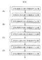
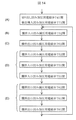
以下,図4の操作フローを用いて本実施例の試料処理装置の操作を説明する。操作を開始する前の状態として,駆動部40は試料処理装置に設置され,空気配管70が接続されている。最初の操作である,分析チップ装着201では,操作者は分析チップ10およびメンブレン20を駆動部40に装着し,蓋30を閉じる。この状態が図2の(B)である。なお,分析チップ10およびメンブレン20は通常一体となってパッケージングされおり,このパッケージングされたものを駆動部40に装着する。 Hereinafter, the operation of the sample processing apparatus of this embodiment will be described using the operation flow of FIG. As a state before starting the operation, the drive unit 40 is installed in the sample processing device and the air pipe 70 is connected. In the analysis chip mounting 201, which is the first operation, the operator mounts the analysis chip 10 and the membrane 20 on the drive unit 40 and closes the lid 30. This state is shown in FIG. 2B. The analysis chip 10 and the membrane 20 are usually packaged together, and the packaged one is mounted on the drive unit 40.

次の装置動作開始202において,操作者は,操作部61から分析内容に応じた制御手順を選択して,装置動作を開始する。試料処理装置は,初期化動作203を開始し,電磁弁の開閉動作やポンプによる加圧及び減圧操作,必要に応じて圧力のチェックなどを行う。 At the next device operation start 202, the operator selects a control procedure according to the analysis content from the operation unit 61 and starts the device operation. The sample processing device starts the initialization operation 203, opens and closes the solenoid valve, pressurizes and depressurizes with a pump, and checks the pressure as necessary.

その後,加圧用ポンプ71及び減圧用ポンプ72を動作させた状態で,減圧用電磁弁712等は全て閉じ,少なくとも加圧用電磁弁711と7F1は開いた状態で待機状態開始204となる。 After that, with the pressurizing pump 71 and the depressurizing pump 72 operating, all the depressurizing solenoid valves 712 and the like are closed, and at least the pressurizing solenoid valves 711 and 7F1 are opened to enter the standby state start 204.

待機状態になると,投入操作205において,操作者は,試料投入窓32から試料を試料用ウエル11に投入し,同様に試薬投入窓33から試薬を試薬用ウエル15に投入する。このとき,加圧用電磁弁711及び7F1が開いているため,凹み41及び4Fが加圧され,両溝部でメンブレン20が分析チップ下面に押し付けられているため,溝111および151が封止され,試料用ウエル11および試薬用ウエル15からそれぞれ試料と試薬が流出することはない。 In the standby state, in the charging operation 205, the operator charges the sample into the sample well 11 through the sample charging window 32, and similarly charges the reagent into the reagent well 15 through the reagent charging window 33. At this time, since the pressurizing solenoid valves 711 and 7F1 are open, the recesses 41 and 4F are pressurized, and the membrane 20 is pressed against the lower surface of the analysis chip at both grooves, so that the grooves 111 and 151 are sealed. The sample and the reagent do not flow out from the sample well 11 and the reagent well 15, respectively.

試料及び試薬の投入を完了すると,操作者は操作部61から分析動作開始206の指示を出し,試料処理装置は分析動作207を実施する。分析が終了すると,分析結果は試料処理装置内のメモリに格納され,必要に応じて操作部61のディスプレイなどに表示される。 When the charging of the sample and the reagent is completed, the operator issues an instruction of the analysis operation start 206 from the operation unit 61, and the sample processing apparatus performs the analysis operation 207. When the analysis is completed, the analysis result is stored in the memory in the sample processing apparatus and displayed on the display of the operation unit 61 or the like as needed.

分析動作207が終了すると,分析チップ取外し208で,操作者は分析チップ10及びメンブレン20を外して保管あるいは廃棄する。次の分析がある場合は,分析チップ装着201に戻って,新しい分析チップを搭載し,分析を実施する。分析がない場合は,操作者は操作部61で終了操作209を行い,装置を停止する。 When the analysis operation 207 is completed, at the analysis chip removal 208, the operator removes the analysis chip 10 and the membrane 20 and stores or discards them. If there is the next analysis, return to the analysis chip mounting 201, mount a new analysis chip, and perform the analysis. If there is no analysis, the operator performs the end operation 209 on the operation unit 61 to stop the device.

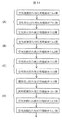
次に,図5を用いて,本実施例の試料処理装置の分析動作207の詳細を説明する。 Next, the details of the analysis operation 207 of the sample processing apparatus of this embodiment will be described with reference to FIG.

図5の試料導入212では,試料用ウエル11に保持されている試料を,試料廃棄用ウエル13まで送液することにより,定量溝115に導入する。試料廃棄213では,空気とり込み用ウエル12から空気を導入して,余分な試料を試料廃棄用ウエル13に廃棄する。試料切り出し214では,空気とり込み用ウエル12から空気を導入して,定量溝115に保持された試料を攪拌用ウエル14に切り出す。以上の試料導入212,試料廃棄213,試料切り出し214の一連の動作が,試料を定量する試料定量211である。 In the sample introduction 212 of FIG. 5, the sample held in the sample well 11 is introduced into the metering groove 115 by sending the liquid to the sample disposal well 13. In the sample disposal 213, air is introduced from the air intake well 12, and the excess sample is discarded into the sample disposal well 13. In the sample cutting out 214, air is introduced from the air intake well 12, and the sample held in the metering groove 115 is cut out into the stirring well 14. The series of operations of sample introduction 212, sample disposal 213, and sample extraction 214 are the sample quantification 211 for quantifying the sample.

以下試料定量211の詳細を説明する。まず,試料導入212について,図6,図7ab及び図8を用いて説明する。 The details of the sample quantification 211 will be described below. First, the sample introduction 212 will be described with reference to FIGS. 6, 7ab and 8.

図6は本実施例の試料処理装置の加圧用電磁弁及び減圧用電磁弁の開閉制御による試料導入動作フローを示す図,図7abはその試料導入動作の説明図,図8は試料の保持状態を示す説明図である。なお,図7abに示す実線の矢印は各加圧管及び減圧管に対応する電磁弁が開いていることを示しており,上向き実線矢印は加圧用電磁弁が開くことで凹みが加圧されることを,下向き実線矢印は減圧用電磁弁が開くことで凹みが減圧されることを示している。実線矢印をつけていない個所では,電磁弁は閉じているが,参照中の図の説明で特に電磁弁が閉じたことを説明するために,破線矢印を用いた。すなわち,上向き破線矢印は加圧用電磁弁が開から閉に切り替わったことを,下向き破線矢印は減圧用電磁弁が開から閉に切り替わったことを示している。 FIG. 6 is a diagram showing a sample introduction operation flow by controlling the opening and closing of the pressurizing solenoid valve and the depressurizing solenoid valve of the sample processing apparatus of this embodiment, FIG. 7ab is an explanatory diagram of the sample introduction operation, and FIG. 8 is a sample holding state. It is explanatory drawing which shows. The solid arrow shown in FIG. 7ab indicates that the solenoid valve corresponding to each pressurizing tube and the pressure reducing tube is open, and the upward solid arrow indicates that the dent is pressurized by opening the pressurizing solenoid valve. The downward solid arrow indicates that the dent is decompressed by opening the solenoid valve for decompression. The solenoid valve is closed where the solid arrow is not attached, but the dashed arrow was used to explain that the solenoid valve was closed in the explanation of the figure being referenced. That is, the upward dashed arrow indicates that the pressurizing solenoid valve has switched from open to closed, and the downward dashed arrow indicates that the depressurizing solenoid valve has switched from open to closed.

図6の(A),図7aの(A)(断面AA)は,上述した分析動作開始時点の状態で,試料用ウエル11に試料80が保持されている。すなわち,図7aの(A)では,試料封止凹み加圧用電磁弁711が開いているため,試料封止凹み用加圧管411から空気が流入して,試料封止凹み41が加圧され,試料封止凹み用減圧管412側の試料封止凹み減圧用電磁弁712は閉じている。また,図示していないが,試薬用ウエル15には試薬が保持され,同様に試薬封止凹み加圧用電磁弁7F1が開いているため,同じく試薬封止凹み4Fが加圧されている。 In FIGS. 6A and 7a (A) (cross section AA), the sample 80 is held in the sample well 11 in the state at the start of the analysis operation described above. That is, in FIG. 7a (A), since the sample sealing recess pressurizing solenoid valve 711 is open, air flows in from the sample sealing recess pressurizing tube 411 to pressurize the sample sealing recess 41. The solenoid valve 712 for reducing the sample sealing dent on the side of the pressure reducing tube 412 for the sample sealing dent is closed. Further, although not shown, the reagent is held in the reagent well 15, and the reagent sealing recess 4F is similarly pressurized because the reagent sealing recess pressurizing solenoid valve 7F1 is open.

次に図6の(B),図7aの(B)(断面AA)に示すように,試料流動凹み加圧用電磁弁721を開くことで,試料流動凹み用加圧管421から空気を流入させて,試料流動凹み42を加圧し,試料封止凹み加圧用電磁弁711を閉じることで,試料封止凹み用加圧管411からの空気の流入を止め,試料封止凹み減圧用電磁弁712を開くことで,試料封止凹み用減圧管412から空気を流出させ,試料封止凹み41を減圧する。このとき,メンブレン20は試料封止凹み41の底面に引き寄せられるため,メンブレン20と分析チップ10との間に試料封止部隙間413が発生し,試料80を試料用ウエル11から試料封止上流溝111を経て試料封止部隙間413に引き込む。 Next, as shown in (B) of FIG. 6 and (B) (section AA) of FIG. 7a, by opening the sample flow recess pressurizing solenoid valve 721, air is allowed to flow in from the sample flow recess pressurizing tube 421. By pressurizing the sample flow recess 42 and closing the sample sealing recess pressurizing solenoid valve 711, the inflow of air from the sample sealing recess pressurizing tube 411 is stopped and the sample sealing recess depressurizing solenoid valve 712 is opened. As a result, air is discharged from the sample sealing recess for reducing pressure tube 412, and the sample sealing recess 41 is depressurized. At this time, since the membrane 20 is attracted to the bottom surface of the sample sealing recess 41, a sample sealing portion gap 413 is generated between the membrane 20 and the analysis chip 10, and the sample 80 is sample-sealed upstream from the sample well 11. It is drawn into the sample sealing portion gap 413 through the groove 111.

次に図6の(C),図7aの(C)(断面AA)に示すように,試料封止凹み減圧用電磁弁712は開いたまま,試料導入凹み加圧用電磁弁731を開くことで,試料導入凹み用加圧管431から空気を流入させて,試料導入凹み43を加圧し,試料流動凹み加圧用電磁弁721を閉じることで,試料流動凹み用加圧管421からの空気の流入を止め,試料流動凹み減圧用電磁弁722を開くことで,試料送液凹み用減圧管422から空気を流出させ,試料流動凹み42を減圧する。このとき,メンブレン20は試料流動凹み42の底面に引き寄せられるため,メンブレン20と分析チップ10との間に試料流動部隙間423が発生し,試料80を試料封止部隙間413から試料流動上流溝112を経て試料流動部隙間423に引き込む。 Next, as shown in (C) of FIG. 6 and (C) (section AA) of FIG. 7a, by opening the sample introduction recess pressurizing solenoid valve 731 while the sample sealing recess depressurizing solenoid valve 712 is open. , Inflow of air from the sample introduction dent pressurizing tube 431, pressurize the sample introduction dent 43, and close the sample flow dent pressurizing solenoid valve 721 to stop the inflow of air from the sample flow dent pressurizing tube 421. By opening the solenoid valve 722 for reducing the pressure of the sample flow dent, air is discharged from the pressure reducing tube 422 for the sample flow dent to reduce the pressure of the sample flow dent 42. At this time, since the membrane 20 is attracted to the bottom surface of the sample flow recess 42, a sample flow portion gap 423 is generated between the membrane 20 and the analysis chip 10, and the sample 80 is moved from the sample sealing portion gap 413 to the sample flow upstream groove. It is drawn into the sample flow part gap 423 via 112.

次に図6の(D),図7aの(D)(断面AA)に示すように,試料導入凹み加圧用電磁弁731及び,試料導入凹み減圧用電磁弁722は開いたまま,試料封止凹み減圧用電磁弁712を閉じることで,試料封止凹み用減圧管412からの空気の流出を止め,試料封止凹み加圧用電磁弁711を開くことで,試料封止凹み用加圧管411から空気を流入させ,試料封止凹み41を加圧する。このとき,試料封止凹み41及び試料導入凹み43が加圧されることで,試料流動上流溝112及び試料導入上流溝113は封止され,試料流動部隙間423内に試料80が保持される。 Next, as shown in (D) of FIG. 6 and (D) (section AA) of FIG. 7a, the sample introduction recess pressurizing solenoid valve 731 and the sample introduction recess depressurizing solenoid valve 722 remain open to seal the sample. By closing the dent pressure reducing solenoid valve 712, the outflow of air from the sample sealing dent pressure reducing tube 412 is stopped, and by opening the sample sealing dent pressurizing solenoid valve 711, the sample sealing dent pressurizing tube 411 is used. Air is introduced to pressurize the sample sealing recess 41. At this time, the sample sealing recess 41 and the sample introduction recess 43 are pressurized, so that the sample flow upstream groove 112 and the sample introduction upstream groove 113 are sealed, and the sample 80 is held in the sample flow portion gap 423. ..

次に図6の(E),図7bの(E)(断面AA及び断面BB)に示すように,試料封止凹み加圧用電磁弁711は開いたまま,新たに2か所の凹み,すなわち攪拌入口凹み45と空気流動凹み4Aを加圧し,2か所の凹み,すなわち試料排出凹み4Cと試料廃棄凹み4Dを減圧する。すなわち,攪拌入口凹み加圧用電磁弁751を開くことで,攪拌入口凹み用加圧管451から空気を流入させ,攪拌入口凹み45を加圧し,空気流動凹み加圧用電磁弁7A1を開くことで,空気流動凹み用加圧管4A1から空気を流入させ,空気流動凹み4Aを加圧し,試料排出凹み減圧用電磁弁7C2を開くことで,試料排出凹み用減圧管4C2から空気を流出させ,試料排出凹み4Cを減圧し,試料廃棄凹み減圧用電磁弁7D2を開くことで,試料廃棄凹み用減圧管4D2から空気を流出させ,試料廃棄凹み4Dを減圧する。この状態では,定量溝115に接続する4か所の溝,すなわち試料導入下流溝114,試料排出上流溝133,空気分岐溝124,試料分岐溝143のうち,空気分岐溝124はその上流側にある空気とり込み用ウエル12との間にある空気流動凹み4Aが加圧され,メンブレン20が分析チップ10下面側に押し付けられて封止されており,同様に試料分岐溝143もその下流側にある攪拌用ウエル14との間にある攪拌入口凹み45が加圧され,メンブレン20が分析チップ10下面側に押し付けられて封止されている。一方,試料排出上流溝133はその下流側にある試料廃棄用ウエル13との間にある二つの凹み,すなわち試料排出凹み4Cと試料廃棄凹み4Dが両方とも減圧されて,メンブレン20がそれぞれの凹みの底面に引き寄せられて分析チップ10下面とメンブレン20との間に隙間が発生し,試料排出上流溝133と試料廃棄用ウエル13は連通している。 Next, as shown in (E) of FIG. 6 and (E) of FIG. 7b (cross section AA and cross section BB), the sample sealing recess pressurizing solenoid valve 711 remains open and two new recesses, that is, The stirring inlet dent 45 and the air flow dent 4A are pressurized, and the two dents, that is, the sample discharge dent 4C and the sample disposal dent 4D are depressurized. That is, by opening the stirring inlet dent pressurizing solenoid valve 751, air flows in from the stirring inlet dent pressurizing pipe 451 to pressurize the stirring inlet dent 45, and by opening the air flow dent pressurizing solenoid valve 7A1, air is opened. Air flows in from the flow dent pressure tube 4A1, the air flow dent 4A is pressurized, and the sample discharge dent decompression solenoid valve 7C2 is opened to allow air to flow out from the sample discharge dent pressure reducing tube 4C2, and the sample discharge dent 4C. By opening the solenoid valve 7D2 for reducing the pressure of the sample waste dent, air is discharged from the pressure reducing tube 4D2 for the sample waste dent, and the sample waste dent 4D is depressurized. In this state, of the four grooves connected to the metering groove 115, that is, the sample introduction downstream groove 114, the sample discharge upstream groove 133, the air branch groove 124, and the sample branch groove 143, the air branch groove 124 is on the upstream side. The air flow recess 4A between the well 12 for taking in air is pressurized, and the membrane 20 is pressed against the lower surface side of the analysis chip 10 to be sealed. Similarly, the sample branch groove 143 is also located downstream thereof. The stirring inlet recess 45 between the stirring well 14 is pressurized, and the membrane 20 is pressed against the lower surface side of the analysis chip 10 to be sealed. On the other hand, the sample discharge upstream groove 133 has two recesses between the sample disposal well 13 on the downstream side thereof, that is, both the sample discharge recess 4C and the sample disposal recess 4D are decompressed, and the membrane 20 is each recessed. A gap is generated between the lower surface of the analysis chip 10 and the membrane 20 by being attracted to the bottom surface of the sample, and the sample discharge upstream groove 133 and the sample disposal well 13 communicate with each other.

このような状態で,試料導入凹み加圧用電磁弁731を閉じることで,試料導入凹み用加圧管431からの空気の流入を止め,試料流動凹み減圧用電磁弁722を閉じることで,試料流動凹み用減圧管422からの空気の流出を止める。このとき,試料流動凹み42のメンブレン20は弾性力で元の状態に戻ろうとし,試料80を試料流動部隙間423から押し出そうとする。しかし,試料流動上流溝112は,試料封止凹み41の加圧により封止されているため流出できない。また,試料分岐溝143および空気分岐溝124は,切り出し凹み44および空気導入凹み4Bは加圧されていないが,その先の攪拌入口凹み45および空気流動凹み4Aが加圧され封止されているため,試料あるいは空気が試料分岐溝143あるいは空気分岐溝124に流入しようとすると,切り出し凹み44および空気導入凹み4Bのメンブレンを弾性力に逆らって分析チップ10の下面から剥がさなければならない。一方,試料排出上流133は,試料排出凹み4Cと試料廃棄凹み4Dが両方とも減圧されて試料廃棄用ウエル13に連通しているため,試料80および空気は流出できる。すなわち,試料80は,試料流動部隙間423から試料導入上流溝113を経て,試料導入凹み43のメンブレン20と分析チップ10との間の試料導入部隙間433に侵入し,試料導入下流溝114から定量溝115へと導入され,さらに試料排出上流溝133から,試料排出凹み4Cのメンブレン20と分析チップ10との間の試料排出部隙間4C3,試料排出下流溝132,試料廃棄凹み4Dのメンブレン20と分析チップ10との間の試料廃棄部隙間4D3,試料廃棄下流溝131を経て試料廃棄用ウエル13に流出する。 In such a state, by closing the sample introduction dent pressurizing solenoid valve 731, the inflow of air from the sample introduction dent pressurizing tube 431 is stopped, and by closing the sample flow dent decompression solenoid valve 722, the sample flow dent Stop the outflow of air from the decompression pipe 422. At this time, the membrane 20 of the sample flow recess 42 tries to return to the original state by elastic force, and tries to push the sample 80 out of the sample flow portion gap 423. However, the sample flow upstream groove 112 cannot flow out because it is sealed by the pressurization of the sample sealing recess 41. Further, in the sample branch groove 143 and the air branch groove 124, the cutout recess 44 and the air introduction recess 4B are not pressurized, but the stirring inlet recess 45 and the air flow recess 4A beyond them are pressurized and sealed. Therefore, when the sample or air tries to flow into the sample branch groove 143 or the air branch groove 124, the membranes of the cutout recess 44 and the air introduction recess 4B must be peeled off from the lower surface of the analysis chip 10 against the elastic force. On the other hand, in the sample discharge upstream 133, since both the sample discharge dent 4C and the sample disposal dent 4D are decompressed and communicate with the sample disposal well 13, the sample 80 and air can flow out. That is, the sample 80 enters the sample introduction portion gap 433 between the membrane 20 of the sample introduction recess 43 and the analysis chip 10 through the sample introduction upstream groove 113 from the sample flow portion gap 423, and enters from the sample introduction downstream groove 114. It is introduced into the metering groove 115, and further, from the sample discharge upstream groove 133, the sample discharge portion gap 4C3 between the sample discharge recess 4C membrane 20 and the analysis chip 10, the sample discharge downstream groove 132, and the sample disposal recess 4D membrane 20. It flows out to the sample disposal well 13 through the sample disposal section gap 4D3 between the sample disposal chip 10 and the sample disposal downstream groove 131.

最後に,試料流動凹み用加圧管721を開くことで,試料流動凹み42を加圧し,メンブレンを分析チップ10に押し付けることで試料80を完全に押し出す。 Finally, the sample flow dent 42 is pressed by opening the sample flow dent pressure tube 721, and the membrane is pressed against the analysis chip 10 to completely push out the sample 80.

次に,図6の(F)および図7bの(F)(断面BB)に示すように,空気導入凹み加圧用電磁弁7A1は開いたまま,試料排出凹み減圧用電磁弁7C2および試料廃棄凹み減圧用電磁弁7D2を閉じることで,試料排出凹み4Cおよび試料廃棄凹み4Dからの空気の流出を止める。なお,このとき,図示はしていないが,試料流動凹み加圧用電磁弁721および攪拌入口凹み加圧用電磁弁751は開いたままである。このようにすることで,試料排出部隙間4C3および試料廃棄部隙間4D3ではメンブレンが弾性力で分析チップ10の下面側に戻り,試料80を試料廃棄用ウエル13に押し出す。 Next, as shown in (F) of FIG. 6 and (F) (cross section BB) of FIG. 7b, the solenoid valve 7A1 for pressurizing the air introduction recess is left open, and the solenoid valve 7C2 for discharging the sample and the solenoid valve 7C2 for reducing the pressure of the sample are discarded. By closing the solenoid valve 7D2 for decompression, the outflow of air from the sample discharge recess 4C and the sample disposal recess 4D is stopped. At this time, although not shown, the sample flow recess pressurizing solenoid valve 721 and the stirring inlet recess pressurizing solenoid valve 751 remain open. By doing so, in the sample discharge portion gap 4C3 and the sample disposal portion gap 4D3, the membrane returns to the lower surface side of the analysis chip 10 by elastic force, and the sample 80 is pushed out to the sample disposal well 13.

この状態で,図8の(A)に示すように,試料80は,定量溝115に満たされる。なお,試料80は,試料封止上流溝111,試料流動上流溝112,試料導入上流溝113,試料導入下流溝114,試料排出上流溝133,試料排出下流溝132,試料廃棄下流溝131にも満たされるが,空気分岐溝124とその上流の空気とり込み用ウエル12側の溝,試料分岐溝143とその下流の攪拌用ウエル14側の溝には侵入しない。 In this state, as shown in FIG. 8A, the sample 80 fills the quantification groove 115. The sample 80 is also applied to the sample encapsulation upstream groove 111, the sample flow upstream groove 112, the sample introduction upstream groove 113, the sample introduction downstream groove 114, the sample discharge upstream groove 133, the sample discharge downstream groove 132, and the sample disposal downstream groove 131. Although it is filled, it does not penetrate into the air branch groove 124 and the groove on the air intake well 12 side upstream thereof, and the sample branch groove 143 and the groove on the stirring well 14 side downstream thereof.

ここまでが,図5の試料導入212,すなわち,試料用ウエル11に保持された試料80を,定量溝115に導入する動作である。 Up to this point, the sample introduction 212 of FIG. 5, that is, the operation of introducing the sample 80 held in the sample well 11 into the quantification groove 115.

なお,本実施例では,試料が定量溝115に導入される以降の,図7bの(E)および(F)では,定量溝115に最も近い凹み,すなわち試料導入凹み43,切り出し凹み44,空気導入凹み4B,試料排出凹み4Cは加圧をしていない。これは,定量溝115に最も近い凹みを加圧すると,定量溝115でメンブレンが押し上げられ,容積が減少し定量性に影響が出る可能性があるからである。例えば,図7bの(E)で,空気流動凹み4Aを加圧するのではなく,空気導入凹み4Bを加圧すると,加圧された空気は空気分岐溝124下部のメンブレン20を押し上げ,さらに分岐溝115下部のメンブレン20を押し上げる。そのため,わずかではあるが定量溝115の容積が減少し,保持される液量が少なくなる。定量溝115への試料の導入終了後に空気導入凹み4Bの加圧を停止すれば,定量溝115のメンブレン20は弾性力で元の状態に戻るので,定量溝115の容積は所定の容積に戻る。このとき,定量溝115に液が戻ってくれば定量性は失われないが,空気が侵入するようであれば,液量は減少したままになる。 In this embodiment, in FIGS. 7b (E) and 7b after the sample is introduced into the quantification groove 115, the dent closest to the quantification groove 115, that is, the sample introduction dent 43, the cutout dent 44, and air. The introduction dent 4B and the sample discharge dent 4C are not pressurized. This is because when the recess closest to the quantification groove 115 is pressed, the membrane is pushed up by the quantification groove 115, the volume is reduced, and the quantification may be affected. For example, in FIG. 7b (E), when the air introduction recess 4B is pressurized instead of pressurizing the air flow recess 4A, the pressurized air pushes up the membrane 20 under the air branch groove 124, and further, the branch groove. Push up the membrane 20 at the bottom of 115. Therefore, the volume of the metering groove 115 is slightly reduced, and the amount of liquid held is reduced. If the pressurization of the air introduction recess 4B is stopped after the introduction of the sample into the metering groove 115 is completed, the membrane 20 of the metering groove 115 returns to the original state by the elastic force, so that the volume of the metering groove 115 returns to the predetermined volume. .. At this time, if the liquid returns to the quantification groove 115, the quantification is not lost, but if air invades, the amount of the liquid remains reduced.

そのため,本実施例の分析チップ10では,定量溝115に試料を導入する時点以降では,定量溝115に最も近い4か所の凹みを加圧しないようにしている。 Therefore, in the analysis chip 10 of this embodiment, after the time when the sample is introduced into the quantification groove 115, the four dents closest to the quantification groove 115 are not pressurized.

次に,図5の試料廃棄213を,図9及び図10abを用いて説明する。 Next, the sample disposal 213 of FIG. 5 will be described with reference to FIGS. 9 and 10ab.

図9は本実施例の試料処理装置の加圧用電磁弁及び減圧用電磁弁の開閉制御による試料廃棄動作フローを示す図,図10abはその試料廃棄動作の説明図である。 FIG. 9 is a diagram showing a sample disposal operation flow by controlling the opening and closing of the pressurizing solenoid valve and the depressurizing solenoid valve of the sample processing apparatus of this embodiment, and FIG. 10ab is an explanatory diagram of the sample disposal operation.

図9の(A),図10aの(A)(断面BB)は,図6の(F),図7bの(F)からの続きの動作で,空気流動凹み加圧用電磁弁7A1は開いたまま,空気封止凹み減圧用電磁弁792を開くことで,空気封止凹み用減圧管492から空気を流出させ,空気封止凹み49を減圧する。このとき,メンブレン20は空気封止凹み49の底面に引き寄せられるため,メンブレン20と分析チップ10との間に空気封止部隙間493が発生し,空気を空気とり込み用ウエル12から空気封止上流溝121を経て空気封止部隙間493に引き込む。 (A) of FIG. 9 and (A) of FIG. 10a (cross section BB) are continuous operations from (F) of FIG. 6 and (F) of FIG. 7b, and the solenoid valve 7A1 for pressurizing the air flow dent is opened. By opening the solenoid valve 792 for reducing the pressure of the air-sealed recess, air is discharged from the pressure reducing pipe 492 for the air-sealed recess, and the pressure of the air-sealed recess 49 is reduced. At this time, since the membrane 20 is attracted to the bottom surface of the air sealing recess 49, an air sealing portion gap 493 is generated between the membrane 20 and the analysis chip 10, and air is sealed from the air intake well 12. It is drawn into the air sealing portion gap 493 through the upstream groove 121.

次に図9の(B),図10aの(B)(断面BB)に示すように,空気封止凹み減圧用電磁弁792は開いたまま,空気流動凹み加圧用電磁弁7A1を閉じることで,空気流動凹み用加圧管4A1からの空気の流入を止め,空気流動凹み減圧用電磁弁7A2を開くことで,空気流動凹み用減圧管4A2から空気を流出させ,空気流動凹み4Aを減圧する。このとき,メンブレン20は空気流動凹み4Aの底面に引き寄せられるため,メンブレン20と分析チップ10との間に空気流動部隙間4A3が発生し,空気を空気封止部隙間493から空気流動上流溝122を経て空気流動部隙間4A3に引き込む。 Next, as shown in (B) of FIG. 9 and (B) (cross section BB) of FIG. 10a, by closing the air flow recess pressurizing solenoid valve 7A1 while the air sealing recess depressurizing solenoid valve 792 is open. By stopping the inflow of air from the air flow dent pressure tube 4A1 and opening the air flow dent decompression solenoid valve 7A2, the air flows out from the air flow dent pressure reducing tube 4A2 and the air flow dent 4A is depressurized. At this time, since the membrane 20 is attracted to the bottom surface of the air flow recess 4A, an air flow portion gap 4A3 is generated between the membrane 20 and the analysis chip 10, and air is flowed from the air sealing portion gap 493 to the air flow upstream groove 122. It is drawn into the air flow part gap 4A3 through.

次に図9の(C),図10aの(C)(断面BB)に示すように,空気流動凹み減圧用電磁弁7A2は開いたまま,空気封止凹み減圧用電磁弁792を閉じることで,空気封止凹み用減圧管492からの空気の流出を止め,空気封止凹み加圧用電磁弁791を開くことで,空気封止凹み用加圧管491から空気を流入させ,空気封止凹み49を加圧する。このとき,空気封止凹み49が加圧されることで,空気流動上流溝122は封止され,空気流動部隙間4A3内に空気が保持される。 Next, as shown in (C) of FIG. 9 and (C) (cross section BB) of FIG. 10a, the air-sealing dent reducing solenoid valve 7A2 is left open, and the air-sealing dent reducing solenoid valve 792 is closed. By stopping the outflow of air from the air-sealing dent pressure reducing pipe 492 and opening the air-sealing dent pressurizing solenoid valve 791, air can flow in from the air-sealing dent pressurizing pipe 491, and the air-sealing dent 49 Pressurize. At this time, the air sealing recess 49 is pressurized, so that the air flow upstream groove 122 is sealed and air is held in the air flow portion gap 4A3.

次に図9の(D),図10bの(D)(断面AA及び断面BB)に示すように,空気封止凹み加圧用電磁弁791は開いたまま,空気流動凹み減圧用電磁弁7A2を閉じることで,空気流動凹み用減圧管4A2からの空気の流出を止め,空気流動凹み加圧用電磁弁7A1を開くことで,空気流動凹み用加圧管4A1から空気を流入させ,空気流動凹み4Aを加圧する。このとき,試料流動凹み加圧用電磁弁721と攪拌入口凹み加圧用電磁弁751は開いた状態で,試料流動凹み42と攪拌入口凹み45は加圧されている。このようにすることで,空気流動凹み4Aでは,メンブレン20が空気流動部隙間4A3内の空気を押し出そうとする。しかし,空気封止凹み49,試料流動凹み42及び攪拌入口凹み45は加圧されているため,空気流動部隙間4A3内の空気は,空気封止上流溝122および定量溝115側に移動することができず,試料排出上流溝133から,加圧されていない試料排出凹み4Cのメンブレン20と分析チップ10との間の隙間,試料排出下流溝132,加圧されていない試料廃棄凹み4Dのメンブレン20と分析チップ10との間の隙間,試料廃棄下流溝131へと移動し,試料を試料廃棄用ウエル13へと押し出す。 Next, as shown in (D) of FIG. 9 and (D) of FIG. 10b (cross section AA and cross section BB), the air-sealing recess pressurizing solenoid valve 791 is left open, and the air flow recess depressurizing solenoid valve 7A2 is opened. By closing, the outflow of air from the air flow dent pressure reducing tube 4A2 is stopped, and by opening the air flow dent pressurizing solenoid valve 7A1, air flows in from the air flow dent pressurizing tube 4A1 to make the air flow dent 4A. Pressurize. At this time, the sample flow recess 42 and the stirring inlet recess 45 are pressurized while the sample flow recess pressurizing solenoid valve 721 and the stirring inlet recess pressurizing solenoid valve 751 are open. By doing so, in the air flow recess 4A, the membrane 20 tends to push out the air in the air flow portion gap 4A3. However, since the air sealing recess 49, the sample flow recess 42, and the stirring inlet recess 45 are pressurized, the air in the air flow portion gap 4A3 moves to the air sealing upstream groove 122 and the metering groove 115 side. The gap between the membrane 20 of the unpressurized sample discharge recess 4C and the analysis chip 10 from the sample discharge upstream groove 133, the sample discharge downstream groove 132, and the membrane of the unpressurized sample disposal recess 4D. The gap between 20 and the analysis chip 10 moves to the sample disposal downstream groove 131, and the sample is pushed out into the sample disposal well 13.

この状態で,図8の(B)に示すように,図8の(A)のときに保持された,試料排出上流溝133,試料排出下流溝132,試料廃棄下流溝131内の試料80は,試料廃棄用ウエル13に流出している。 In this state, as shown in (B) of FIG. 8, the sample 80 in the sample discharge upstream groove 133, the sample discharge downstream groove 132, and the sample disposal downstream groove 131 held at the time of FIG. 8 (A) is , Outflowing to the sample disposal well 13.

ここまでが,図5の試料廃棄213,すなわち,定量溝115の下流にある試料排出上流溝133,試料排出下流溝132,試料廃棄下流溝131内の試料を,試料廃棄用ウエル13に排出する動作である。 Up to this point, the sample disposal 213 in FIG. 5, that is, the sample discharge upstream groove 133 downstream of the metering groove 115, the sample discharge downstream groove 132, and the sample in the sample disposal downstream groove 131 are discharged to the sample disposal well 13. It is an operation.

次に,図5の試料切り出し214を,図11及び図12abを用いて説明する。 Next, the sample cutout 214 of FIG. 5 will be described with reference to FIGS. 11 and 12ab.

図11は本実施例の試料処理装置の加圧用電磁弁及び減圧用電磁弁の開閉制御による試料切り出し動作フローを示す図,図12abはその試料切り出し動作の説明図である。 FIG. 11 is a diagram showing a sample cutting operation flow by controlling the opening and closing of the pressurizing solenoid valve and the depressurizing solenoid valve of the sample processing apparatus of this embodiment, and FIG. 12ab is an explanatory diagram of the sample cutting operation.

図11の(A),図12aの(A)(断面BB)は,図9の(D),図10bの(D)からの続きの動作で,最初に空気封止凹み加圧用電磁弁791を閉じる以外は,(A)から(C)までの動作は全く同じである。すなわち,(A)では,空気流動凹み加圧用電磁弁7A1は開いたまま,空気封止凹み加圧用電磁弁791を閉じ,空気封止凹み減圧用電磁弁792を開くことで空気封止凹み49を減圧し,空気を空気封止部隙間493に引き込む。(B)では,空気流動凹み加圧用電磁弁7A1を閉じ,空気流動凹み減圧用電磁弁7A2を開くことで空気流動凹み4Aを減圧し,空気を空気流動部隙間4A3まで引き込む。(C)では,空気封止凹み減圧用電磁弁792を閉じ,空気封止凹み加圧用電磁弁791を開くことで,空気封止凹み49を加圧することで封止し,空気流動部隙間4A3に空気を保持する。 (A) of FIG. 11 and (A) (cross section BB) of FIG. 12a are continuous operations from (D) of FIG. 9 and (D) of FIG. 10b, and first, an air-sealing recess pressurizing solenoid valve 791. Except for closing, the operations from (A) to (C) are exactly the same. That is, in (A), the air sealing recess 49 is opened by closing the air sealing recess pressurizing solenoid valve 791 and opening the air sealing recess depressurizing solenoid valve 792 while keeping the air flow recess pressurizing solenoid valve 7A1 open. Is depressurized and air is drawn into the air sealing gap 493. In (B), the air flow dent 4A is depressurized by closing the air flow dent pressurizing solenoid valve 7A1 and opening the air flow dent depressurizing solenoid valve 7A2, and the air is drawn into the air flow portion gap 4A3. In (C), the air sealing recess 49 is sealed by pressing the air sealing recess 49 by closing the air sealing recess reducing solenoid valve 792 and opening the air sealing recess pressurizing solenoid valve 791, and the air flow portion gap 4A3. Hold air in.

次に図11の(D),図12bの(D)(断面AA及び断面BB)に示すように,攪拌出口凹み加圧用電磁弁761と試料廃棄凹み加圧用電磁弁7D1を開くことで,攪拌出口凹み46と試料廃棄凹み4Dを加圧して封止する。このとき,試料流動凹み加圧用電磁弁721も開いて試料流動凹み42も加圧,封止している。この状態で,空気流動凹み減圧用電磁弁7A2を閉じ,空気流動凹み加圧用電磁弁7A1を開くと,空気流動凹み4Aでは,メンブレン20が空気流動部隙間4A3内の空気を押し出そうとするが,空気流動凹み49及び試料廃棄凹み4Dは加圧されているため,空気流動部隙間4A3内の空気は,空気導入上流溝122および試料排出上流溝133側に移動することができず,定量溝115へと移動し定量溝115内の試料を押し出す。しかし,試料流動凹み42は封止されているので,試料は,試料導入下流溝114側に移動することができず,試料分岐溝143から,加圧されていない切り出し凹み44のメンブレン20と分析チップ10との間の隙間,切り出し下流溝142,加圧されていない攪拌入口凹み45のメンブレン20と分析チップ10との間の隙間,攪拌入口下流溝141へと移動し,攪拌用ウエル14へ押し出される。 Next, as shown in (D) of FIG. 11 and (D) of FIG. 12b (cross section AA and cross section BB), stirring is performed by opening the stirring outlet dent pressurizing solenoid valve 761 and the sample waste dent pressurizing solenoid valve 7D1. The outlet recess 46 and the sample disposal recess 4D are pressurized and sealed. At this time, the sample flow dent pressurizing solenoid valve 721 is also opened to pressurize and seal the sample flow dent 42. In this state, when the air flow dent depressurizing electromagnetic valve 7A2 is closed and the air flow dent pressurizing electromagnetic valve 7A1 is opened, the membrane 20 tries to push out the air in the air flow portion gap 4A3 in the air flow dent 4A. However, since the air flow dent 49 and the sample disposal dent 4D are pressurized, the air in the air flow portion gap 4A3 cannot move to the air introduction upstream groove 122 and the sample discharge upstream groove 133 side, and is quantified. It moves to the groove 115 and pushes out the sample in the metering groove 115. However, since the sample flow dent 42 is sealed, the sample cannot move to the sample introduction downstream groove 114 side, and is analyzed from the sample branch groove 143 as the membrane 20 of the unpressurized cutout dent 44. Move to the gap between the tip 10, the cut-out downstream groove 142, the gap between the membrane 20 of the unpressurized stirring inlet recess 45 and the analysis chip 10, the stirring inlet downstream groove 141, and to the stirring well 14. Extruded.

この状態で,図8の(C)に示すように,図8の(A)及び(B)のときに定量溝115に保持された試料が,攪拌用ウエル14に流出している。 In this state, as shown in FIG. 8C, the sample held in the metering groove 115 at the time of FIGS. 8A and 8 flows out to the stirring well 14.

ここまでが,図5の試料切り出し214,すなわち,定量溝115にある試料を攪拌用ウエル14に切り出す動作である。 Up to this point, the sample cutting out 214 of FIG. 5, that is, the operation of cutting out the sample in the metering groove 115 into the stirring well 14.

以上の,図5の試料導入212,試料廃棄213及び試料切り出し214の動作が試料定量211である。すなわち,試料用ウエル11内の試料を,一端試料廃棄用ウエル13に流すことで,定量溝115に試料を保持し,定量溝115に保持された試料のみを攪拌用ウエル14に空気で追い出すことにより,攪拌用ウエル14内に一定量,すなわち定量溝115の容積と同じ液量の試料が保持される。 The above-mentioned operations of the sample introduction 212, the sample disposal 213, and the sample cutting 214 in FIG. 5 are the sample quantification 211. That is, by flowing the sample in the sample well 11 into the sample disposal well 13 once, the sample is held in the metering groove 115, and only the sample held in the metering groove 115 is expelled by air into the stirring well 14. As a result, a fixed amount of sample, that is, the same amount of liquid as the volume of the metering groove 115, is held in the stirring well 14.

なお,本実施例では試料導入212の次に試料廃棄213を実施し,試料切り出し214を実施したが,試料廃棄213の動作は省略することができ,試料導入212に続いて試料切り出し214を実施してもよい。 In this example, sample disposal 213 was performed after sample introduction 212, and sample cutting 214 was performed. However, the operation of sample disposal 213 could be omitted, and sample cutting 214 was performed following sample introduction 212. You may.

図5の試料定量211が終了すると,次に試薬導入215が実施される。この動作は,図1において,試薬用ウエル15内の試薬を攪拌用ウエル14に移動するもので,試料導入212と同様の動作になるので,電磁弁制御による試薬導入の動作フローを図13に示し,図1と図3の符号を参照して,動作を説明する。 When the sample quantification 211 of FIG. 5 is completed, the reagent introduction 215 is then carried out. In FIG. 1, this operation moves the reagent in the reagent well 15 to the stirring well 14, and the operation is the same as that of the sample introduction 212. Therefore, the operation flow of reagent introduction by solenoid valve control is shown in FIG. The operation will be described with reference to the reference numerals shown in FIGS. 1 and 3.

図13の(A)は初期状態で,試薬封止凹み加圧用電磁弁7F1が開いており,試薬封止凹み4Fが加圧されているため封止され,試薬用ウエル15内の試薬は流出しない。 In FIG. 13A, in the initial state, the reagent sealing recess pressurizing solenoid valve 7F1 is open, and the reagent sealing recess 4F is pressurized, so that the reagent is sealed and the reagent in the reagent well 15 flows out. do not do.

図13の(B)で,試薬封止凹み加圧用電磁弁7F1を閉じ,試薬封止凹み減圧用電磁弁7F2を開くことで試薬封止凹み4Fを減圧し,メンブレン20と分析チップ10下面との間に発生する隙間に,試薬用ウエル15から試薬を引き込む。 In FIG. 13B, the reagent sealing recess 4F is depressurized by closing the reagent sealing recess pressurizing solenoid valve 7F1 and opening the reagent sealing recess depressurizing solenoid valve 7F2, and the membrane 20 and the lower surface of the analysis chip 10 The reagent is drawn from the reagent well 15 into the gap generated between the two.

図13の(C)で,試薬流動凹み減圧用電磁弁7E2を開くことで試薬流動凹み4Eを減圧し,メンブレン20と分析チップ10下面との間に発生する隙間に,さらに試薬を引き込む。 In FIG. 13C, the reagent flow recess 4E is depressurized by opening the reagent flow recess decompression solenoid valve 7E2, and the reagent is further drawn into the gap generated between the membrane 20 and the lower surface of the analysis chip 10.

図13の(D)で,検出部導入凹み加圧用電磁弁771を開くことで検出部導入凹み47を加圧して封止し,さらに,試薬封止凹み減圧用電磁弁7F2を閉じ,試薬封止凹み加圧用電磁弁7F1を開くことで,空気封止凹み4Fを加圧することで封止する。 In FIG. 13D, the detection unit introduction recess 47 is pressurized and sealed by opening the detection unit introduction recess pressurizing solenoid valve 771, and the reagent sealing recess pressure reducing solenoid valve 7F2 is closed to seal the reagent. By opening the solenoid valve 7F1 for pressurizing the stop dent, the air sealing dent 4F is pressurized to seal.

図13の(E)で,試薬流動凹み減圧用電磁弁7E2を閉じ,試薬流動凹み加圧用電磁弁7E1を開くことで試薬流動凹み4Eを加圧し,試薬を押し出す。このとき,試薬封止凹み4Fは封止されているため試薬流動下流溝152側に試薬は移動できず,試薬流動上流溝153から合流溝154へと移動する。さらに,検出部導入凹み47が封止されているため,検出部導入上流溝165側に試薬は移動できず,攪拌出口下流溝145から,加圧されていない攪拌出口凹み46のメンブレン20と分析チップ10との間の隙間,攪拌出口上流溝144へと移動し,攪拌用ウエル14へ押し出される。 In FIG. 13 (E), the reagent flow recess 4E is pressurized by closing the reagent flow recess reducing solenoid valve 7E2 and opening the reagent flow recess pressurizing solenoid valve 7E1 to push out the reagent. At this time, since the reagent sealing recess 4F is sealed, the reagent cannot move to the reagent flow downstream groove 152 side, and moves from the reagent flow upstream groove 153 to the confluence groove 154. Further, since the detection unit introduction recess 47 is sealed, the reagent cannot move to the detection unit introduction upstream groove 165 side, and the membrane 20 of the stirring outlet recess 46 that is not pressurized is analyzed from the stirring outlet downstream groove 145. It moves to the gap between the tip 10 and the stirring outlet upstream groove 144, and is pushed out to the stirring well 14.

ここまでが,図5の試薬導入215,すなわち,試薬用ウエル15内の試薬を攪拌用ウエル14に移動する動作である。 Up to this point, the reagent introduction 215 in FIG. 5, that is, the operation of moving the reagent in the reagent well 15 to the stirring well 14.

このようにして,試料定量211で試料が,試薬導入215で試薬が攪拌用ウエル14に保持されたことになる。なお,試料と試薬が攪拌用ウエル14に保持されればよいので,試薬導入215の後に試薬定量211を実施してもよい。 In this way, the sample was held in the stirring well 14 by the sample quantification 211 and the reagent introduction 215. Since the sample and the reagent may be held in the stirring well 14, the reagent quantification 211 may be carried out after the reagent introduction 215.

試料は定量溝の容積で定量されるが,試薬は試薬流動凹み4Eの容積,正確にはメンブレン20の厚み分を差し引いた容積で定量される。あるいは,試薬は,試薬用ウエル15への注入量で定量される。すなわち,試薬流動凹み4Eで定量する場合は,定量したい液量より多めの試薬を試薬用ウエル15に注入し,試薬導入215の動作を実施することで,所定の液量を攪拌用ウエル14に移動することができる。あるいは,試薬用ウエル15への注入量で定量する場合は,試薬流動凹み4Eの容積より少ない量を試薬用ウエル15に注入すればよい。大きな液量を定量したい場合は,試薬導入215の動作を複数回実施すればよい。 The sample is quantified by the volume of the quantification groove, but the reagent is quantified by the volume of the reagent flow recess 4E, to be exact, the volume obtained by subtracting the thickness of the membrane 20. Alternatively, the reagent is quantified by the amount injected into the reagent well 15. That is, when quantifying with the reagent flow recess 4E, a predetermined amount of liquid is poured into the well 14 for stirring by injecting a reagent larger than the amount of liquid to be quantified into the well 15 for reagent and performing the operation of the reagent introduction 215. Can be moved. Alternatively, when quantifying by the amount injected into the reagent well 15, an amount smaller than the volume of the reagent flow recess 4E may be injected into the reagent well 15. If it is desired to quantify a large amount of liquid, the operation of reagent introduction 215 may be performed a plurality of times.

なお,メンブレン20を変形させることで液体を流動させるため,変形量があまり小さいと定量性が得にくくなる。そのため,微量液を定量する場合,試薬導入215では試薬流動凹みを小さくしてメンブレン20の変形量を小さくする必要があるのに対して,試料定量211で用いた定量溝115の方式は,試料流動凹み42を小さくする必要はなく,微量液の定量に向いている。したがって,試料定量211と試薬導入215のどちらを使用するかは,液量と定量再現性の仕様に依存する。 Since the liquid is made to flow by deforming the membrane 20, if the amount of deformation is too small, it becomes difficult to obtain quantitativeness. Therefore, when quantifying a trace amount of liquid, it is necessary to reduce the amount of deformation of the membrane 20 by reducing the reagent flow dent in the reagent introduction 215, whereas the method of the quantification groove 115 used in the sample quantification 211 is a sample. It is not necessary to reduce the flow dent 42, and it is suitable for quantification of trace liquids. Therefore, whether to use sample quantification 211 or reagent introduction 215 depends on the liquid volume and quantification reproducibility specifications.

本実施例では,試料の定量に定量溝115を使用し,試薬の定量には試薬流動凹みの容積を使用したが,試薬の定量にも定量溝を使用,すなわち試料用と試薬用の二つの定量溝,あるいは一本の定量溝を順番に使用する,などの方法が考えられる。 In this example, the quantification groove 115 was used for quantifying the sample, and the volume of the reagent flow recess was used for quantifying the reagent. However, the quantification groove was also used for quantifying the reagent, that is, two for the sample and the reagent. A method such as using a metering groove or one metering groove in order can be considered.

次に,図5の攪拌216を,図14及び図15abを用いて説明する。 Next, the stirring 216 of FIG. 5 will be described with reference to FIGS. 14 and 15ab.

図14は本実施例の試料処理装置の加圧用電磁弁及び減圧用電磁弁の開閉制御による攪拌動作フローを示す図,図15abはその攪拌動作の説明図である。 FIG. 14 is a diagram showing a stirring operation flow by controlling the opening and closing of the pressurizing solenoid valve and the depressurizing solenoid valve of the sample processing apparatus of this embodiment, and FIG. 15ab is an explanatory diagram of the stirring operation.

図14の(A),図15aの(A)(断面AA)は,攪拌用ウエル14に試料と試薬が保持されている状態で,切り出し凹み加圧用電磁弁741と検出導入凹み加圧用電磁弁771を開くことで,切り出し凹み44と検出導入凹み47を加圧し,封止している。 14 (A) and 15a (A) (cross section AA) show a cut-out recess pressurizing solenoid valve 741 and a detection introduction recess pressurizing solenoid valve in a state where the sample and the reagent are held in the stirring well 14. By opening 771, the cutout dent 44 and the detection introduction dent 47 are pressurized and sealed.

図14の(B),図15aの(B)(断面AA)では,攪拌入口凹み減圧用電磁弁752を開くことで攪拌入口凹み45を減圧し,メンブレン20と分析チップ10との間に発生する隙間である攪拌入口部隙間453に液を引き込む。 In (B) of FIG. 14 and (B) (cross section AA) of FIG. 15a, the stirring inlet recess 45 is depressurized by opening the stirring inlet recess reducing solenoid valve 752, and the stirring inlet recess 45 is depressurized and generated between the membrane 20 and the analysis chip 10. The liquid is drawn into the stirring inlet gap 453, which is the gap between the two.

図14の(C),図15aの(C)(断面AA)では,攪拌出口凹み減圧用電磁弁762を開くことで攪拌出口凹み46を減圧し,メンブレン20と分析チップ10との間に発生する隙間である攪拌出口部隙間463に液を引き込む。 In (C) of FIG. 14 and (C) (cross section AA) of FIG. 15a, the stirring outlet recess 46 is depressurized by opening the stirring outlet recess decompression solenoid valve 762, and the stirring outlet recess 46 is generated between the membrane 20 and the analysis chip 10. The liquid is drawn into the stirring outlet gap 463, which is the gap between the two.

図14の(D),図15aの(D)(断面AA)では,攪拌入口凹み減圧用電磁弁752を閉じ,攪拌入口凹み加圧用電磁弁751を開くことで攪拌入口凹み45を加圧し,攪拌入口部隙間453の液を攪拌用ウエル14に戻して,攪拌入口凹み加圧用電磁弁751を閉じる。 In (D) of FIG. 14 and (D) (cross section AA) of FIG. 15a, the stirring inlet recess 45 is pressurized by closing the stirring inlet recess reducing solenoid valve 752 and opening the stirring inlet recess pressurizing solenoid valve 751. The liquid in the stirring inlet gap 453 is returned to the stirring well 14, and the stirring inlet recessed pressurizing solenoid valve 751 is closed.

図14の(E),図15bの(E)(断面AA)では,攪拌出口凹み減圧用電磁弁762を閉じ,攪拌出口凹み加圧用電磁弁761を開くことで,攪拌出口部隙間463の液を攪拌用ウエル14に戻して,攪拌出口凹み加圧用電磁弁761を閉じる。 In (E) of FIG. 14 and (E) (cross section AA) of FIG. 15b, the liquid in the agitation outlet gap 463 is formed by closing the stirring outlet recessed solenoid valve 762 and opening the stirring outlet recess pressurizing solenoid valve 761. Is returned to the stirring well 14, and the stirring outlet recessed pressurizing solenoid valve 761 is closed.

以上の(B)から(E)までの操作を繰り返すことで,攪拌用ウエル14内の液は,攪拌入口凹み45と攪拌出口凹み46へ移動し,再び戻ってくる度に攪拌される。 By repeating the above operations (B) to (E), the liquid in the stirring well 14 moves to the stirring inlet recess 45 and the stirring outlet recess 46, and is stirred each time it returns again.

ここまでが,図5の攪拌216の動作である。 Up to this point, the operation of stirring 216 in FIG. 5 is performed.

次に,図5の計測217を,図16と図1,図3を用いて説明する。図16は本実施例の試料処理装置の加圧用電磁弁及び減圧用電磁弁の開閉制御による計測動作フローを示す図である。 Next, the measurement 217 of FIG. 5 will be described with reference to FIGS. 16 and 1 and 3. FIG. 16 is a diagram showing a measurement operation flow by controlling the opening and closing of the pressurizing solenoid valve and the depressurizing solenoid valve of the sample processing apparatus of this embodiment.

図16の(A)では,攪拌出口凹み減圧用電磁弁762を開くことで,攪拌出口凹み46を減圧し,攪拌終了後の攪拌用ウエル14に保持された混合液を攪拌出口上流溝144から吸引する。 In FIG. 16A, the stirring outlet recess 46 is depressurized by opening the stirring outlet recessing solenoid valve 762, and the mixed solution held in the stirring well 14 after the stirring is completed is discharged from the stirring outlet upstream groove 144. Suction.

次に,図16の(B)では,検出導入部凹み減圧用電磁弁772を開くことで,検出部導入凹み47を減圧し,混合液を攪拌出口下流溝145および検出部上流溝から吸引する。 Next, in FIG. 16B, the detection introduction portion introduction recess 47 is depressurized by opening the detection introduction portion recess decompression solenoid valve 772, and the mixed solution is sucked from the stirring outlet downstream groove 145 and the detection portion upstream groove. ..

次に,図16の(C)では,試薬流動凹み加圧用電磁弁7E1を開くことで,試薬流動凹み4Eを加圧,封止し,攪拌出口凹み減圧用電磁弁762を閉じ,攪拌出口凹み加圧用電磁弁761を開くことで,攪拌出口凹み46を加圧する。 Next, in FIG. 16C, the reagent flow recess 4E is pressurized and sealed by opening the reagent flow recess pressurizing solenoid valve 7E1, the stirring outlet recess is closed, and the stirring outlet recess is closed. By opening the pressurizing solenoid valve 761, the stirring outlet recess 46 is pressurized.

次に,図16の(D)で,検出部導入凹み減圧用電磁弁772を閉じる。このとき,検出部導入凹み47のメンブレン20は弾性力により分析チップ10の下面側に戻ろうとし,混合液を押し出す。攪拌出口凹み46及び試薬流動凹み4Eは封止されているので,混合液は,混合液を検出部下流溝164,検出溝163,混合液廃棄上流溝162を満たしながら,加圧されていない混合液廃棄凹み48のメンブレン20と分析チップ10との間の隙間,混合液廃棄下流溝161へと移動し,余分な混合液は混合液廃棄用ウエル16へ押し出される。 Next, in FIG. 16D, the solenoid valve 772 for reducing the pressure of the detection unit introduction recess is closed. At this time, the membrane 20 of the detection portion introduction recess 47 tries to return to the lower surface side of the analysis chip 10 by elastic force, and pushes out the mixed solution. Since the stirring outlet recess 46 and the reagent flow recess 4E are sealed, the mixture is not pressurized while filling the detection section downstream groove 164, detection groove 163, and mixture disposal upstream groove 162. The gap between the membrane 20 of the liquid disposal recess 48 and the analysis chip 10 moves to the mixed liquid disposal downstream groove 161 and the excess mixed liquid is pushed out to the mixed liquid disposal well 16.

この状態で,図2の観測窓34から観測光を検出溝163に照射し,データを取得する。
ここまでが,図5の計測217の動作であり,これで図4の分析動作207が終了する。
In this state, the observation groove 163 is irradiated with the observation light from the observation window 34 of FIG. 2, and data is acquired.
Up to this point, the operation of the measurement 217 in FIG. 5 is completed, and the analysis operation 207 in FIG. 4 is completed.

なお,検出溝163は,液を密閉空間に保持する機能を持ち,以上詳述した実施例1では,観測窓34から観測光を検出溝164に照射し,データを取得する分析動作を示したが,本実施例の処理用溝における処理は分析・検出に限定されるものではない。例えば,図5の攪拌216で2液を攪拌した後,検出溝163に保持することで反応させ,その後混合液廃棄用ウエル16から回収してもよく,あるいは検出溝163に液を保持して温度を制御するなど光学的な計測以外の処理を行ってもよい。 The detection groove 163 has a function of holding the liquid in a closed space, and in Example 1 described in detail above, an analysis operation of irradiating the detection groove 164 with observation light from the observation window 34 and acquiring data was shown. However, the processing in the processing groove of this example is not limited to analysis / detection. For example, after stirring the two liquids with the stirring 216 of FIG. 5, the two liquids may be reacted by holding them in the detection groove 163 and then recovered from the mixture disposal well 16, or the liquids may be held in the detection groove 163. Processing other than optical measurement may be performed, such as controlling the temperature.

本発明によれば,メンブレン20を空気圧で変形させることで液体及び気体を流し,定量溝115に一端液を保持後,定量溝115内の液を空気で追い出すことにより一定量の液を定量することができる。特に,定量溝の容積を変えることで,その他の溝や凹みの形状あるいは電磁弁切り替えの制御動作を変更することなく,所定量の定量操作が可能となる。 According to the present invention, a certain amount of liquid is quantified by flowing liquid and gas by deforming the membrane 20 by air pressure, holding the liquid once in the quantification groove 115, and then expelling the liquid in the quantification groove 115 with air. be able to. In particular, by changing the volume of the metering groove, it is possible to perform a predetermined amount of metering operation without changing the shape of other grooves or recesses or the control operation of solenoid valve switching.

図5の(E)の動作で述べたように,実施例1では定量溝115に最も近い4か所の凹みを加圧しないで,その隣の凹みを加圧するように工夫している。そのため,例えば試料導入(図5の212)の動作では,試料用ウエル11から試料廃棄用ウエル13に試料を送る際に,5つの凹みを使用している。すなわち,試料封止凹み41,試料流動凹み42,試料導入凹み43,試料排出凹み4C,試料廃棄凹み4Dである。 As described in the operation of FIG. 5 (E), in the first embodiment, the dents at the four locations closest to the metering groove 115 are not pressurized, but the dents adjacent to the dents are pressurized. Therefore, for example, in the operation of sample introduction (212 in FIG. 5), five dents are used when the sample is sent from the sample well 11 to the sample disposal well 13. That is, the sample sealing dent 41, the sample flow dent 42, the sample introduction dent 43, the sample discharge dent 4C, and the sample disposal dent 4D.

しかし,本発明のように,凹みの圧力を制御してメンブレンを変形させて流体を移動する場合,3つの凹みがあれば流体を移動させることができる。すなわち試薬の導入では,試薬封止凹み4F,試薬流動凹み4E,攪拌出口凹み46の3つの凹みで送液することができる。 However, as in the present invention, when the pressure of the dent is controlled to deform the membrane to move the fluid, the fluid can be moved if there are three dents. That is, when the reagent is introduced, the liquid can be fed through three recesses: the reagent sealing recess 4F, the reagent flow recess 4E, and the stirring outlet recess 46.

そこで,3つの凹みを使用して定量を実現する試料処理装置を図17に示す。図1との違いは,図1に示した定量溝115に最も近い4か所の凹み,試料封止凹み41,試料流動凹み42,試料導入凹み43,試料排出凹み4C,試料廃棄凹み4Dがなく,定量溝115が分析チップ10の下面側,すなわちメンブレン20と接触する側ではなく,上面側に設けてある点である。図1と同じ構造には同じ符号をつけており,異なるのは,分析チップ上面側にある定量溝815と,試料導入上流溝113の下流側末端から分析チップ上面側に連通する試料導入縦穴816と,さらに試料導入縦穴816から定量溝815に連通する試料導入下流溝814,切り出し下流溝142の下流側末端から分析チップ上面側に連通する試料分岐縦穴844と,さらに試料分岐縦穴844から定量溝815に連通する切り出し上流溝843,空気導入上流溝123の下流側末端から分析チップ上面側に連通する空気導入縦穴825と,さらに空気導入縦穴825から定量溝815に連通する空気分岐溝824,試料排出下流溝132の下流側末端から分析チップ上面側に連通する試料排出縦穴834と,さらに試料排出縦穴834から定量溝815に連通する試料排出上流溝833である。なお,分析チップ10の上面側に設けた試料導入下流溝814,定量溝815,空気分岐溝824,試料排出上流溝833はカバー850で密封されている。 Therefore, FIG. 17 shows a sample processing apparatus that realizes quantification using three recesses. The difference from FIG. 1 is that there are four dents closest to the metering groove 115 shown in FIG. 1, a sample sealing dent 41, a sample flow dent 42, a sample introduction dent 43, a sample discharge dent 4C, and a sample disposal dent 4D. The point is that the metering groove 115 is provided not on the lower surface side of the analysis chip 10, that is, on the side in contact with the membrane 20, but on the upper surface side. The same structure as in FIG. 1 is designated by the same reference numerals, and the difference is that the quantification groove 815 on the upper surface side of the analysis chip and the sample introduction vertical hole 816 communicating from the downstream end of the sample introduction upstream groove 113 to the upper surface side of the analysis chip. Further, the sample introduction downstream groove 814 communicating from the sample introduction vertical hole 816 to the quantification groove 815, the sample branch vertical hole 844 communicating from the downstream end of the cutout downstream groove 142 to the analysis chip upper surface side, and the sample branch vertical hole 844 to the quantification groove. Cut-out upstream groove 843 that communicates with 815, air introduction vertical hole 825 that communicates from the downstream end of the air introduction upstream groove 123 to the upper surface side of the analysis chip, and air branch groove 824 that communicates from the air introduction vertical hole 825 to the metering groove 815. The sample discharge vertical hole 834 communicates from the downstream end of the discharge downstream groove 132 to the upper surface side of the analysis chip, and the sample discharge upstream groove 833 communicates from the sample discharge vertical hole 834 to the metering groove 815. The sample introduction downstream groove 814, the metering groove 815, the air branch groove 824, and the sample discharge upstream groove 833 provided on the upper surface side of the analysis chip 10 are sealed with a cover 850.

図5の試料定量211は,実施例1で説明した図6から図12abまでと同じであるが,定量溝115に最も近い4か所の凹部に対する制御動作を除いたものである。このとき,図17の分析チップ10では,定量溝815に最も近い凹部が加圧されることになるが,定量溝815はメンブレン20に接していないので,メンブレンの変形による容積変化の影響を受けないため,定量性が失われない。 The sample quantification 211 of FIG. 5 is the same as that of FIGS. 6 to 12ab described in the first embodiment, except for the control operation for the four recesses closest to the quantification groove 115. At this time, in the analysis chip 10 of FIG. 17, the recess closest to the quantification groove 815 is pressurized, but since the quantification groove 815 is not in contact with the membrane 20, it is affected by the volume change due to the deformation of the membrane. Since there is no such thing, the quantitativeness is not lost.

実施例1では,試料用ウエル11に保持されている試料を,試料廃棄用ウエル13まで送液することにより,定量溝115に導入し,定量溝115に導入された試料を攪拌用ウエル14へ切り出すことで,試料を定量している。 In Example 1, the sample held in the sample well 11 is introduced into the metering groove 115 by sending the liquid to the sample disposal well 13, and the sample introduced into the metering groove 115 is introduced into the stirring well 14. The sample is quantified by cutting it out.

試料用ウエル11から定量溝115に試料を導入する前は,試料用ウエル11から定量溝115までの各溝,すなわち,試料封止上流溝111,試料流動上流溝112,試料導入上流溝113,試料導入下流溝114には空気が存在し,試料を導入する際に,それぞれの空気が定量溝115を通過し,試料廃棄用ウエル13に排出される。すなわち,図7aの(B)に示すように,試料80を試料用ウエル11から試料封止上流溝111を経て試料封止部隙間413に引き込む際に,試料封止上流溝111に存在した空気は試料封止部隙間413の下流端(図の右側)に引き寄せられ,次の図7の(C)では,試料流動上流溝112の空気と合わせて試料流動部隙間423の下流端(図の右側)に引き寄せられ,常に試料と空気の位置関係が変わらず,上流側に試料が,下流側に空気が保持されれば,試料の流動にともなって空気は試料廃棄用ウエル13に排出される。 Before introducing the sample from the sample well 11 to the metering groove 115, each groove from the sample well 11 to the metering groove 115, that is, the sample sealing upstream groove 111, the sample flow upstream groove 112, the sample introduction upstream groove 113, Air exists in the sample introduction downstream groove 114, and when the sample is introduced, each air passes through the metering groove 115 and is discharged to the sample disposal well 13. That is, as shown in FIG. 7a (B), the air present in the sample sealing upstream groove 111 when the sample 80 is drawn from the sample well 11 through the sample sealing upstream groove 111 into the sample sealing portion gap 413. Is attracted to the downstream end (right side of the figure) of the sample sealing part gap 413, and in (C) of FIG. 7 below, the downstream end of the sample flow part gap 423 (in the figure) together with the air of the sample flow upstream groove 112. If the sample is attracted to the right side) and the positional relationship between the sample and the air does not change, and the sample is held on the upstream side and the air is held on the downstream side, the air is discharged to the sample disposal well 13 as the sample flows. ..

しかし,試料封止部隙間413等の各隙間の形状や大きさによっては,試料を引き込む際に,試料と空気の位置が逆転したり,空気が分裂したりする可能性がある。もし,試料と空気の位置が逆転すると,試料廃棄用ウエル13に試料が排出された後で定量溝115に空気が流入し,定量性が失われる可能性がある。 However, depending on the shape and size of each gap such as the sample sealing portion gap 413, the positions of the sample and the air may be reversed or the air may split when the sample is drawn. If the positions of the sample and the air are reversed, air may flow into the quantification groove 115 after the sample is discharged into the sample disposal well 13, and the quantification may be lost.

そこで,本実施例では,試料を定量溝115に導入する前に,各溝の空気を除去することで,定量溝115への空気の混入を防止する構造について述べる。 Therefore, in this embodiment, a structure for preventing air from entering the metering groove 115 by removing air from each groove before introducing the sample into the metering groove 115 will be described.

図18に,空気除去機構を設けた分析チップを示す。なお,図1と同じ構造には同じ符号をつけている。 FIG. 18 shows an analysis chip provided with an air removal mechanism. The same structure as in FIG. 1 is designated by the same reference numeral.

図18の(A)は分析チップ10の上面側からみた図で,図1の(B),(C),(D)は,それぞれ図1(A)のAA断面,BB断面,CC断面である。なお,各断面図は,定量操作に関連する部分の断面図となっている。 FIG. 18A is a view seen from the upper surface side of the analysis chip 10, and FIGS. 1B, 1C, and 1D are AA cross sections, BB cross sections, and CC cross sections of FIG. 1 (A), respectively. is there. Each cross-sectional view is a cross-sectional view of a part related to the quantitative operation.

図18では,図1に比べて空気除去に必要な機構が追加あるいは修正されており,以下の動作説明の中で,追加および修正個所を述べる。 In FIG. 18, the mechanism required for air removal has been added or modified as compared with FIG. 1, and the addition and modification points will be described in the following operation description.

空気除去操作は,図5の試料定量211の直前に行う操作であり,図4の操作フローについては同じである。ただし,図4の投入操作205に関して,実施例1では,操作者が試料投入窓32から試料を試料用ウエル11に投入するとき,加圧用電磁弁711を開き,凹み41を加圧することで,溝111を封止し,試料用ウエル11から試料が流出しないようにしているが,本実施例では,図18の(B)に示すように,試料用ウエル11の直下にある試料保持縦穴845および縦穴空気導入溝171からの試料流出を防ぐため,試料封止凹み41および縦穴空気導入凹み4Gの両方を加圧する。 The air removal operation is an operation performed immediately before the sample quantification 211 of FIG. 5, and the operation flow of FIG. 4 is the same. However, regarding the charging operation 205 of FIG. 4, in the first embodiment, when the operator charges the sample into the sample well 11 through the sample charging window 32, the pressurizing electromagnetic valve 711 is opened and the recess 41 is pressurized. The groove 111 is sealed to prevent the sample from flowing out from the sample well 11, but in this embodiment, as shown in FIG. 18B, the sample holding vertical hole 845 directly below the sample well 11 is formed. In order to prevent the sample from flowing out from the vertical hole air introduction groove 171, both the sample sealing recess 41 and the vertical hole air introduction recess 4G are pressurized.

空気除去操作では,試料保持縦穴845の空気と,試料封止下流溝181(図18(B))および試料流動溝182(図18(A))に存在する空気を除去する。 In the air removal operation, the air in the sample holding vertical hole 845 and the air existing in the sample sealing downstream groove 181 (FIG. 18 (B)) and the sample flow groove 182 (FIG. 18 (A)) are removed.

まず,試料保持縦穴845の空気を除去する操作について説明する。まず,縦穴空気導入凹み4Gを減圧することでメンブレン20が引き寄せられ,縦穴空気導入凹み4G上部のメンブレン20と分析チップ10との間に発生した隙間に,試料保持縦穴845の空気および試料用ウエル11内の試料が引き込まれる。次に,縦穴空気流動凹み4Hを減圧することで,縦穴空気流動凹み4H上部のメンブレン20と分析チップ10との間に発生した隙間に,空気および試料が引き込まれる。次に,縦穴空気排出凹み4Jを加圧しながら縦穴空気導入凹み4Gを加圧することで,縦穴空気導入凹み4G上部の隙間を閉じて試料を試料用ウエル11に戻す。次に,縦穴空気排出凹み4Jの加圧を止め,縦穴空気流動凹み4Hの減圧を止めるあるいは加圧することで試料を試料廃棄用ウエル13に排出する。この操作により,試料保持縦穴845の空気は試料廃棄用ウエル13に排出され,試料保持縦穴845は試料で満たされる。 First, an operation of removing air from the sample holding vertical hole 845 will be described. First, the membrane 20 is attracted by depressurizing the vertical hole air introduction recess 4G, and the air and sample wells of the sample holding vertical hole 845 are inserted into the gap generated between the membrane 20 above the vertical hole air introduction recess 4G and the analysis chip 10. The sample in 11 is drawn in. Next, by depressurizing the vertical hole air flow recess 4H, air and a sample are drawn into the gap generated between the membrane 20 above the vertical hole air flow recess 4H and the analysis chip 10. Next, by pressurizing the vertical hole air introduction recess 4G while pressurizing the vertical hole air discharge recess 4J, the gap above the vertical hole air introduction recess 4G is closed and the sample is returned to the sample well 11. Next, the pressurization of the vertical hole air discharge recess 4J is stopped, and the decompression of the vertical hole air flow recess 4H is stopped or pressurized to discharge the sample to the sample disposal well 13. By this operation, the air in the sample holding vertical hole 845 is discharged to the sample disposal well 13, and the sample holding vertical hole 845 is filled with the sample.

次に,試料封止下流溝181および試料流動溝182の空気を除去する操作について説明する。まず,試料封止凹み41を減圧することで,試料封止凹み41上部のメンブレン20と分析チップ10との間に発生した隙間に試料が引き込まれる。このとき,試料保持縦穴845の空気は既に除去してあるので,上記隙間には空気は入らない。次に,試料流動凹み4Kを減圧することで,試料流動凹み4K上部のメンブレン20と分析チップ10との間に発生した隙間に,試料封止下流溝181および試料流動溝182内の空気を先頭にして試料が引き込まれる。次に,溝空気排出凹み4Lおよび試料導入凹み43を加圧しながら試料封止凹み41を加圧することで,試料封止凹み41上部の隙間を閉じて試料を試料用ウエル11に戻す。次に,溝空気排出凹み4Lの加圧を止め,試料排出凹み4Cを加圧するが試料廃棄凹み4Dは加圧しない状態で試料流動凹み4Kの減圧を止めるあるいは加圧することで試料を試料廃棄用ウエル13に排出する。この操作により,試料封止下流溝181および試料流動溝182の空気は試料廃棄用ウエル13に排出され,試料封止下流溝181および試料流動溝182は試料で満たされる。 Next, the operation of removing air from the sample sealing downstream groove 181 and the sample flow groove 182 will be described. First, by depressurizing the sample sealing recess 41, the sample is drawn into the gap generated between the membrane 20 above the sample sealing recess 41 and the analysis chip 10. At this time, since the air in the sample holding vertical hole 845 has already been removed, no air enters the gap. Next, by depressurizing the sample flow dent 4K, the air in the sample sealing downstream groove 181 and the sample flow groove 182 is introduced into the gap generated between the membrane 20 above the sample flow dent 4K and the analysis chip 10. The sample is drawn in. Next, by pressurizing the sample sealing recess 41 while pressing the groove air discharge recess 4L and the sample introduction recess 43, the gap above the sample sealing recess 41 is closed and the sample is returned to the sample well 11. Next, the pressurization of the groove air discharge dent 4L is stopped and the sample discharge dent 4C is pressurized, but the sample waste dent 4D is not pressurized and the sample flow dent 4K is stopped or pressurized to dispose of the sample. Discharge to well 13. By this operation, the air in the sample sealing downstream groove 181 and the sample flow groove 182 is discharged to the sample disposal well 13, and the sample sealing downstream groove 181 and the sample flow groove 182 are filled with the sample.

ここまでが空気除去操作で,続いて図5の試料定量211が実行される。この後の操作は実施例1と同じであるが,凹みや溝の配置が異なる個所があるので,以下に相違点のみ説明する。 The air removal operation up to this point is followed by the sample quantification 211 of FIG. Subsequent operations are the same as in the first embodiment, but since there are places where the dents and grooves are arranged differently, only the differences will be described below.

図5の試料導入212では,試料用ウエル11に保持されている試料を,試料廃棄用ウエル13まで送液することにより,定量溝115に導入している。図18の実施例では,この操作を以下のように実行する。 In the sample introduction 212 of FIG. 5, the sample held in the sample well 11 is introduced into the metering groove 115 by sending the liquid to the sample disposal well 13. In the embodiment of FIG. 18, this operation is executed as follows.

まず,試料封止凹み41を減圧することで,試料封止凹み41上部のメンブレン20と分析チップ10との間に発生した隙間に試料が引き込まれる。次に,試料流動凹み4Kを減圧することで,試料流動凹み4K上部のメンブレン20と分析チップ10との間に発生した隙間に試料が引き込まれる。このとき,試料封止下流溝181および試料流動溝182内の空気は既に除去してあるので,上記隙間に空気は入らない。次に,溝空気排出凹み4Lおよび試料導入凹み43を加圧しながら試料封止凹み41を加圧することで,試料封止凹み41上部の隙間を閉じて試料を試料用ウエル11に戻す。次に,試料導入凹み43の加圧を止め,試料排出凹み4Cおよび試料廃棄凹み4Dを減圧しながら試料流動凹み4Kの減圧を止めるあるいは加圧することで試料を定量溝115に導入し,試料廃棄用ウエル13に排出する。この操作により,試料は試料導入下流溝114,定量溝115,試料排出上流溝133等に満たされる。 First, by depressurizing the sample sealing recess 41, the sample is drawn into the gap generated between the membrane 20 above the sample sealing recess 41 and the analysis chip 10. Next, by depressurizing the sample flow dent 4K, the sample is drawn into the gap generated between the membrane 20 above the sample flow dent 4K and the analysis chip 10. At this time, since the air in the sample sealing downstream groove 181 and the sample flow groove 182 has already been removed, air does not enter the gap. Next, by pressurizing the sample sealing recess 41 while pressing the groove air discharge recess 4L and the sample introduction recess 43, the gap above the sample sealing recess 41 is closed and the sample is returned to the sample well 11. Next, the pressurization of the sample introduction recess 43 is stopped, and the sample is introduced into the quantitative groove 115 by stopping or pressurizing the sample flow recess 4K while reducing the pressure of the sample discharge recess 4C and the sample disposal recess 4D, and the sample is discarded. Discharge to the use well 13. By this operation, the sample is filled in the sample introduction downstream groove 114, the metering groove 115, the sample discharge upstream groove 133, and the like.

この後の,図5の試料廃棄213では,空気とり込み用ウエル12から空気を吸引して,試料廃棄用ウエル13に送ることで,試料排出上流溝133の試料を試料廃棄用ウエル13に排出し,図5の試料切り出し214では,空気とり込み用ウエル12から空気を吸引して,攪拌用ウエル14に送ることで,定量溝115の試料を攪拌用ウエル14に排出する。実施例1と異なるのは,空気とり込み用ウエル12,空気封止凹み49,空気流動凹み4A,空気導入凹み4Bの流路系と,試料廃棄用ウエル13,試料廃棄凹み4D,試料排出凹み4Cの流路系が,定量溝115に対して反対側の位置に変更になっている点で,これは,試料廃棄用ウエル13を,空気除去操作における空気の排出用に使用するための変更である。 In the sample disposal 213 of FIG. 5 after this, air is sucked from the air intake well 12 and sent to the sample disposal well 13, so that the sample in the sample discharge upstream groove 133 is discharged to the sample disposal well 13. Then, in the sample cutting out 214 of FIG. 5, air is sucked from the air intake well 12 and sent to the stirring well 14, so that the sample in the metering groove 115 is discharged to the stirring well 14. The difference from the first embodiment is the flow path system of the air intake well 12, the air sealing recess 49, the air flow recess 4A, the air introduction recess 4B, the sample disposal well 13, the sample disposal recess 4D, and the sample discharge recess. In that the flow path system of 4C is changed to the position opposite to the metering groove 115, this is a change for using the sample disposal well 13 for discharging air in the air removal operation. Is.

図5の試料定量211が終了すると,試薬導入215,攪拌216,計測217の各操作が実行されるが,これらの操作に関係する流路系の配置(図18)は実施例1(図1)と同じであり,動作も全く同じである。 When the sample quantification 211 of FIG. 5 is completed, each operation of reagent introduction 215, stirring 216, and measurement 217 is executed, and the arrangement of the flow path system (FIG. 18) related to these operations is described in Example 1 (FIG. 1). ), And the operation is exactly the same.

本実施例では,試料保持縦穴845の空気と,試料封止下流溝181および試料流動溝182の空気を除去している。すなわち,試料用ウエル11およびその直下の試料保持縦穴845を試料封止凹み41の上部に配置し,縦穴空気導入溝171の一端を試料保持縦穴845に接続し,他端を縦穴空気導入凹み4Gの上部に配置し,縦穴空気導入凹み4Gを減圧することで試料保持縦穴845の空気を除去し,試料保持縦穴845を試料で満たしている。そのため,次の操作で試料封止凹み41を減圧しても,空気は引き込まれない。また,試料封止下流溝181の一端を試料封止凹み41の上部に,他端を試料導入凹み43の上部に配置し,試料流動溝182の一端を試料流動凹み4Kの上部に,他端を試料導入凹み43の上部に配置した試料封止下流溝181の端部と一致させ,試料流動凹み4Kを減圧することで試料封止下流溝181および試料流動溝182の空気を除去し,試料封止下流溝181および試料流動溝182を試料で満たしている。そのため,次の操作で試料を定量溝115に導入しても空気は混入しない。 In this embodiment, the air in the sample holding vertical hole 845 and the air in the sample sealing downstream groove 181 and the sample flow groove 182 are removed. That is, the sample well 11 and the sample holding vertical hole 845 immediately below the sample well 11 are arranged above the sample sealing recess 41, one end of the vertical hole air introduction groove 171 is connected to the sample holding vertical hole 845, and the other end is the vertical hole air introduction recess 4G. The air in the sample holding vertical hole 845 is removed by depressurizing the vertical hole air introduction recess 4G, and the sample holding vertical hole 845 is filled with the sample. Therefore, even if the sample sealing recess 41 is depressurized by the following operation, air is not drawn in. Further, one end of the sample sealing downstream groove 181 is arranged above the sample sealing recess 41, the other end is arranged above the sample introduction recess 43, and one end of the sample flow groove 182 is arranged above the sample flow recess 4K and the other end. Is aligned with the end of the sample sealing downstream groove 181 arranged above the sample introduction recess 43, and the air in the sample sealing downstream groove 181 and the sample flow groove 182 is removed by reducing the pressure of the sample flow recess 4K to remove the sample. The sealing downstream groove 181 and the sample flow groove 182 are filled with the sample. Therefore, even if the sample is introduced into the metering groove 115 by the following operation, air does not mix.

なお,試料導入下流溝114および定量溝115にも空気は存在するが,断面積が小さく,また断面積変化も小さいため,溝内の空気と試料の位置が逆転することはなく,試料導入下流溝114の上流側に空気がなければ,試料導入下流溝114および定量溝115の空気は押し出され,定量溝115に空気が残ることはない。 Although air is also present in the sample introduction downstream groove 114 and the metering groove 115, since the cross-sectional area is small and the change in cross-sectional area is also small, the positions of the air and the sample in the groove are not reversed, and the sample introduction downstream If there is no air on the upstream side of the groove 114, the air in the sample introduction downstream groove 114 and the metering groove 115 is pushed out, and no air remains in the metering groove 115.

本実施例では,定量溝115への空気の混入を防ぎ,定量性を確保することができる。 In this embodiment, it is possible to prevent air from entering the metering groove 115 and ensure quantitativeness.

10 分析チップ
11 試料用ウエル
12 空気とり込み用ウエル
13 試料廃棄用ウエル
14 攪拌用ウエル
15 試薬用ウエル
16 混合液廃棄用ウエル
111,112,113,114,121,122,123,131,132,141,142,144,145,151,152,153,154,161,162,164,165,171,172,173,174,181,182,183,184,185,186,814,833 溝
115,815 定量溝
124,143,824,843 分岐溝
163 検出溝
20 メンブレン
30 蓋
31 回転支持部
32 試料投入窓
33 試薬投入窓
34 観測窓
40 駆動部
41,42,43,44,45,46,47,48,49,4A,4B,4C,4D,4E,4F,4G,4H,4J,4K,4L 凹み
411,421,431,441,451,461,471,481,491,4A1,4B1,4C1,4D1,4E1,4F1,4G1,4H1,4J1,4K1,4L1 加圧管
412,422,432,442,452,462,472,482,492,4A2,4B2,4C2,4D2,4E2,4F2,4G2,4H2,4J2,4K2,4L2 減圧管
50 筺体
51 ロック機構
60 制御部
61 操作部
70 空気配管
71 加圧用ポンプ
711,721,731,741,751,761,771,781,791,7A1,7B1,7C1,7D1,7E1,7F1,7G1,7H1,7J1,7K1,7L1 加圧用電磁弁
72 減圧用ポンプ
712,722,732,742,752,762,772,782,792,7A2,7B2,7C2,7D2,7E2,7F2,7G2,7H2,7J2,7K2,7L2 減圧用電磁弁
816,825,834,844,845 縦穴
10 Analytical chip 11 Sample well 12 Air intake well 13 Sample disposal well 14 Stirring well 15 Reagent well 16 Mixing solution disposal well 111, 112, 113, 114, 121, 122, 123, 131, 132, 141,142,144,145,151,152,153,154,161,162,164,165,171,172,173,174,181,182,183,184,185,186,814,833 Groove 115, 815 Quantitative groove 124,143,824,843 Branch groove 163 Detection groove 20 Membrane 30 Lid 31 Rotation support 32 Sample charging window 33 Reagent charging window 34 Observation window 40 Driving unit 41, 42, 43, 44, 45, 46, 47 , 48, 49, 4A, 4B, 4C, 4D, 4E, 4F, 4G, 4H, 4J, 4K, 4L Recess 411,421,431,441,451,461,471,481,491,4A1,4B1,4C1 , 4D1,4E1,4F1,4G1,4H1,4J1,4K1,4L1 Pressurized pipe 421,422,432,442,452,462,472,482,492,4A2,4B2,4C2,4D2,4E2,4F2,4G2 4H2, 4J2, 4K2, 4L2 Pressure reducing pipe 50 Housing 51 Lock mechanism 60 Control unit 61 Operation unit 70 Air piping 71 Pressurizing pump 711,721,731,741,751,761,771,781,791,7A1,7B1,7C1 , 7D1,7E1,7F1,7G1,7H1,7J1,7K1,7L1 Pressurizing solenoid valve 72 Pressure reducing pump 712,722,732,742,725,762,772,782,792,7A2,7B2,7C2,7D2 7E2,7F2,7G2,7H2,7J2,7K2,7L2 Solenoid valve for reducing pressure 816,825,834,844,845 Vertical hole

Claims (6)

下面側に流路を有する分析チップ、上面側に複数の凹部を有する駆動部、分析チップと駆動部の間に位置する弾性膜、弾性膜が分析チップ側へ密着するか駆動部側へ密着するかを切り替える空気圧制御部を備えた試料処理装置であって、
分析チップは、液体の定量のための定量流路と、当該定量流路から分岐した少なくとも4つの分岐流路を備え、
駆動部は、4つの分岐流路における定量流路側でない端部のそれぞれの下方に凹部を有し、
それぞれの凹部は前記空気圧制御部に連通していることを特徴とする、試料処理装置。
An analysis chip having a flow path on the lower surface side, a drive unit having a plurality of recesses on the upper surface side, an elastic film located between the analysis chip and the drive unit, and an elastic film adhered to the analysis chip side or to the drive unit side. It is a sample processing device equipped with an air pressure control unit that switches between
The analysis chip includes a quantification channel for quantifying the liquid and at least four branch channels branched from the quantification channel.
The drive unit has recesses below each of the ends of the four branch channels that are not on the metering channel side.
A sample processing apparatus, wherein each recess communicates with the air pressure control unit.
請求項1において、
4つの分岐流路のうち2つの分岐流路は、液体を送液する送液流路であり、残りの2つの分岐流路は、気体を送する送気流路であり、
送液流路の上流側または下流側には、さらに一組の流路及び凹部を有し、かつ、送気流路の上流側または下流側には、さらに一組の流路及び凹部を有し、これらの凹部も前記空気圧制御部に連通していることを特徴とする、試料処理装置。
In claim 1,
Four two branch passages of the branch flow path is a liquid feed passage for feeding the liquid, and the remaining two branch passages are air channel feeding the air feed gas,
An additional set of flow paths and recesses is provided on the upstream side or downstream side of the liquid supply flow path, and a further set of flow paths and recesses are provided on the upstream side or downstream side of the air supply flow path. , A sample processing apparatus, characterized in that these recesses are also communicated with the air pressure control unit.
請求項1において、
4つの分岐流路のうち2つの分岐流路は、液体を送液する送液流路であり、残りの2つの分岐流路は、気体を送液する送気流路であり、
送液流路の上流側または下流側には、さらに二組の流路及び凹部を有し、かつ、送気流路の上流側または下流側には、さらに二組の流路及び凹部を有し、これらの凹部も前記空気圧制御部に連通していることを特徴とする、試料処理装置。
In claim 1,
Of the four branch flow paths, two branch flow paths are liquid supply flow paths that supply liquid, and the remaining two branch flow paths are air supply flow paths that supply gas.
There are two sets of flow paths and recesses on the upstream side or downstream side of the liquid supply flow path, and two sets of flow paths and recesses on the upstream side or downstream side of the air supply flow path. , A sample processing apparatus, characterized in that these recesses are also communicated with the air pressure control unit.
請求項2または3のいずれかにおいて、
前記空気圧制御部によって、弾性膜の動きを制御し、下流側の凹部へ液体を送液することを特徴とする、試料処理装置。
In any of claims 2 or 3,
A sample processing apparatus characterized in that the movement of an elastic membrane is controlled by the air pressure control unit and a liquid is sent to a recess on the downstream side.
請求項2〜4のいずれかにおいて、
送液流路を用いて定量流路内に液体を満たし、その後、送気流路を用いて、定量流路内の液体を下流側へ流すことを特徴とする、試料処理装置。
In any of claims 2-4
A sample processing apparatus characterized in that a liquid feeding flow path is used to fill a quantitative flow path with a liquid, and then an air supply flow path is used to flow the liquid in the quantitative flow path to the downstream side.
請求項2〜4において、
前記送液流路としての分岐流路に更なる一組の分岐流路及び凹部を設けたことを特徴とする、試料処理装置。
In claims 2 to 4,
A sample processing apparatus, characterized in that a further set of branch flow paths and recesses is provided in the branch flow path as the liquid feed flow path.
JP2017123833A 2017-06-26 2017-06-26 Sample processing equipment Active JP6789889B2 (en)

Priority Applications (7)

Application Number Priority Date Filing Date Title
JP2017123833A JP6789889B2 (en) 2017-06-26 2017-06-26 Sample processing equipment
CN201880032745.2A CN110637233A (en) 2017-06-26 2018-05-11 Sample processing device
US16/609,248 US20200047181A1 (en) 2017-06-26 2018-05-11 Sample Processing Device
DE112018001977.2T DE112018001977T5 (en) 2017-06-26 2018-05-11 SAMPLE TREATMENT DEVICE
PCT/JP2018/018259 WO2019003659A1 (en) 2017-06-26 2018-05-11 Sample processing device
GB1915791.6A GB2577406B (en) 2017-06-26 2018-05-11 Sample processing device
SG11201910270XA SG11201910270XA (en) 2017-06-26 2018-05-11 Sample processing device

Applications Claiming Priority (1)

Application Number Priority Date Filing Date Title
JP2017123833A JP6789889B2 (en) 2017-06-26 2017-06-26 Sample processing equipment

Publications (3)

Publication Number Publication Date
JP2019007841A JP2019007841A (en) 2019-01-17
JP2019007841A5 JP2019007841A5 (en) 2020-02-06
JP6789889B2 true JP6789889B2 (en) 2020-11-25

Family

ID=64740544

Family Applications (1)

Application Number Title Priority Date Filing Date
JP2017123833A Active JP6789889B2 (en) 2017-06-26 2017-06-26 Sample processing equipment

Country Status (7)

Country Link
US (1) US20200047181A1 (en)
JP (1) JP6789889B2 (en)
CN (1) CN110637233A (en)
DE (1) DE112018001977T5 (en)
GB (1) GB2577406B (en)
SG (1) SG11201910270XA (en)
WO (1) WO2019003659A1 (en)

Families Citing this family (1)

* Cited by examiner, † Cited by third party
Publication number Priority date Publication date Assignee Title
CN115970781B (en) * 2023-03-21 2024-01-12 杭州霆科生物科技有限公司 Quantitative sample adding structure, concentration gradient micro-fluidic chip and control method thereof

Family Cites Families (6)

* Cited by examiner, † Cited by third party
Publication number Priority date Publication date Assignee Title
EP2367634A1 (en) 2008-12-24 2011-09-28 Heriot-Watt University A microfluidic system and method
JP2011030522A (en) * 2009-08-04 2011-02-17 Aida Engineering Ltd Microfluid device
JP5980030B2 (en) * 2012-07-23 2016-08-31 株式会社日立ハイテクノロジーズ Biochemical processing equipment
CN104969076B (en) * 2013-01-31 2018-04-03 株式会社日立高新技术 The group of biochemistry filter core, biochemistry filter core and filter cartridge seat
JP6002610B2 (en) * 2013-03-19 2016-10-05 株式会社日立ハイテクノロジーズ Liquid feeding device and chemical analyzer using the same
WO2015051776A1 (en) * 2013-10-07 2015-04-16 M2P-Labs Gmbh Microreactor system

Also Published As

Publication number Publication date
US20200047181A1 (en) 2020-02-13
GB201915791D0 (en) 2019-12-18
WO2019003659A1 (en) 2019-01-03
GB2577406A (en) 2020-03-25
JP2019007841A (en) 2019-01-17
GB2577406B (en) 2022-03-30
CN110637233A (en) 2019-12-31
SG11201910270XA (en) 2020-01-30
DE112018001977T5 (en) 2019-12-24

Similar Documents

Publication Publication Date Title
CN101765775B (en) Device for the preparation and fractioned dispensing of fluid samples, dispensing system including such device and related method
EP2492682B1 (en) Microfluidic separation of plasma for colormetric assay
US8741231B2 (en) Flow passage control mechanism for microchip
JP4593451B2 (en) Microreactor system and liquid feeding method
WO2009035062A1 (en) Sample packing device
US20110220656A1 (en) Modular cartridge for liquid transport
WO2018020924A1 (en) Bubble eliminating structure, bubble eliminating method, and agitating method
US20160158747A1 (en) Sample processing device for microchip
US20200164367A1 (en) Structures for automated, multi-stage processing of nanofluidic chips
JP6789889B2 (en) Sample processing equipment
CN109311009A (en) Fluid wriggling layer pump
JPWO2008108481A1 (en) Microchip fluid control mechanism
JP2010065584A (en) Liquid sending pump and liquid sending method by this pump
JP3967331B2 (en) Liquid mixing method, liquid mixing apparatus and microchip
JP6860511B2 (en) Sample processing equipment
JP6654874B2 (en) Storage container, flow cartridge, and discharge mechanism
CN112424610B (en) Sample processing apparatus and device
JP2005334804A (en) Microfluidic system, and treatment method using the same
WO2011013331A1 (en) Micro-fluid chip
US20230364609A1 (en) Sample processing device, sample processing apparatus, and sample processing method
JP6457309B2 (en) Reagent cartridge
US9802191B2 (en) Disposable, fluid actuated, mechanically driven point-of-care invitro-diagnostic apparatus and method of performing a point-of-care invitro-diagnostic test
JP2001004614A (en) Gas diffusion flow injection analyzing method and device therefor
JP2008286733A (en) Sealed-type reactor and reaction detector

Legal Events

Date Code Title Description
A521 Request for written amendment filed

Free format text: JAPANESE INTERMEDIATE CODE: A523

Effective date: 20170628

RD02 Notification of acceptance of power of attorney

Free format text: JAPANESE INTERMEDIATE CODE: A7422

Effective date: 20180824

RD04 Notification of resignation of power of attorney

Free format text: JAPANESE INTERMEDIATE CODE: A7424

Effective date: 20180912

A521 Request for written amendment filed

Free format text: JAPANESE INTERMEDIATE CODE: A523

Effective date: 20191219

A621 Written request for application examination

Free format text: JAPANESE INTERMEDIATE CODE: A621

Effective date: 20191219

TRDD Decision of grant or rejection written
A01 Written decision to grant a patent or to grant a registration (utility model)

Free format text: JAPANESE INTERMEDIATE CODE: A01

Effective date: 20201013

A61 First payment of annual fees (during grant procedure)

Free format text: JAPANESE INTERMEDIATE CODE: A61

Effective date: 20201104

R150 Certificate of patent or registration of utility model

Ref document number: 6789889

Country of ref document: JP

Free format text: JAPANESE INTERMEDIATE CODE: R150