JP6788735B2 - Enhanced mobility reference signals for wireless link monitoring in beam-based systems - Google Patents
Enhanced mobility reference signals for wireless link monitoring in beam-based systems Download PDFInfo
- Publication number
- JP6788735B2 JP6788735B2 JP2019518457A JP2019518457A JP6788735B2 JP 6788735 B2 JP6788735 B2 JP 6788735B2 JP 2019518457 A JP2019518457 A JP 2019518457A JP 2019518457 A JP2019518457 A JP 2019518457A JP 6788735 B2 JP6788735 B2 JP 6788735B2
- Authority
- JP
- Japan
- Prior art keywords
- frequency
- reference signal
- subset
- local range
- local
- Prior art date
- Legal status (The legal status is an assumption and is not a legal conclusion. Google has not performed a legal analysis and makes no representation as to the accuracy of the status listed.)
- Active
Links
- 238000012544 monitoring process Methods 0.000 title claims description 7
- 238000000034 method Methods 0.000 claims description 83
- 238000005259 measurement Methods 0.000 claims description 55
- 238000012545 processing Methods 0.000 claims description 39
- 238000004891 communication Methods 0.000 claims description 18
- 230000001360 synchronised effect Effects 0.000 claims description 3
- 230000000875 corresponding effect Effects 0.000 description 27
- 230000005540 biological transmission Effects 0.000 description 16
- 230000015654 memory Effects 0.000 description 16
- 238000013461 design Methods 0.000 description 15
- 230000008901 benefit Effects 0.000 description 11
- 238000010586 diagram Methods 0.000 description 10
- 230000011664 signaling Effects 0.000 description 10
- 238000004590 computer program Methods 0.000 description 8
- 238000005516 engineering process Methods 0.000 description 8
- 230000000737 periodic effect Effects 0.000 description 7
- 238000011156 evaluation Methods 0.000 description 6
- 238000012935 Averaging Methods 0.000 description 4
- 238000001530 Raman microscopy Methods 0.000 description 4
- 230000006870 function Effects 0.000 description 4
- 230000003068 static effect Effects 0.000 description 4
- 241000700159 Rattus Species 0.000 description 3
- 238000013459 approach Methods 0.000 description 3
- 230000010267 cellular communication Effects 0.000 description 3
- 230000001413 cellular effect Effects 0.000 description 3
- 101150069124 RAN1 gene Proteins 0.000 description 2
- 101100355633 Salmo salar ran gene Proteins 0.000 description 2
- 238000003491 array Methods 0.000 description 2
- 230000002596 correlated effect Effects 0.000 description 2
- 238000001514 detection method Methods 0.000 description 2
- 238000011161 development Methods 0.000 description 2
- 230000005055 memory storage Effects 0.000 description 2
- 230000008054 signal transmission Effects 0.000 description 2
- 238000010408 sweeping Methods 0.000 description 2
- 230000006399 behavior Effects 0.000 description 1
- 235000019800 disodium phosphate Nutrition 0.000 description 1
- 230000000694 effects Effects 0.000 description 1
- 238000001914 filtration Methods 0.000 description 1
- 238000005286 illumination Methods 0.000 description 1
- 230000006872 improvement Effects 0.000 description 1
- 230000007787 long-term memory Effects 0.000 description 1
- 230000007774 longterm Effects 0.000 description 1
- 238000013507 mapping Methods 0.000 description 1
- 230000007246 mechanism Effects 0.000 description 1
- 238000012986 modification Methods 0.000 description 1
- 230000004048 modification Effects 0.000 description 1
- 230000035515 penetration Effects 0.000 description 1
- 230000008569 process Effects 0.000 description 1
- 238000013442 quality metrics Methods 0.000 description 1
- 238000011160 research Methods 0.000 description 1
- 238000012360 testing method Methods 0.000 description 1
- 230000001960 triggered effect Effects 0.000 description 1
- 230000003936 working memory Effects 0.000 description 1
Images


Classifications
-
- H—ELECTRICITY
- H04—ELECTRIC COMMUNICATION TECHNIQUE
- H04B—TRANSMISSION
- H04B7/00—Radio transmission systems, i.e. using radiation field
- H04B7/02—Diversity systems; Multi-antenna system, i.e. transmission or reception using multiple antennas
- H04B7/04—Diversity systems; Multi-antenna system, i.e. transmission or reception using multiple antennas using two or more spaced independent antennas
- H04B7/0413—MIMO systems
- H04B7/0417—Feedback systems
-
- H—ELECTRICITY
- H04—ELECTRIC COMMUNICATION TECHNIQUE
- H04L—TRANSMISSION OF DIGITAL INFORMATION, e.g. TELEGRAPHIC COMMUNICATION
- H04L5/00—Arrangements affording multiple use of the transmission path
- H04L5/003—Arrangements for allocating sub-channels of the transmission path
- H04L5/0048—Allocation of pilot signals, i.e. of signals known to the receiver
- H04L5/005—Allocation of pilot signals, i.e. of signals known to the receiver of common pilots, i.e. pilots destined for multiple users or terminals
-
- H—ELECTRICITY
- H04—ELECTRIC COMMUNICATION TECHNIQUE
- H04B—TRANSMISSION
- H04B17/00—Monitoring; Testing
- H04B17/30—Monitoring; Testing of propagation channels
- H04B17/309—Measuring or estimating channel quality parameters
- H04B17/318—Received signal strength
-
- H—ELECTRICITY
- H04—ELECTRIC COMMUNICATION TECHNIQUE
- H04B—TRANSMISSION
- H04B7/00—Radio transmission systems, i.e. using radiation field
- H04B7/02—Diversity systems; Multi-antenna system, i.e. transmission or reception using multiple antennas
- H04B7/04—Diversity systems; Multi-antenna system, i.e. transmission or reception using multiple antennas using two or more spaced independent antennas
- H04B7/0408—Diversity systems; Multi-antenna system, i.e. transmission or reception using multiple antennas using two or more spaced independent antennas using two or more beams, i.e. beam diversity
-
- H—ELECTRICITY
- H04—ELECTRIC COMMUNICATION TECHNIQUE
- H04B—TRANSMISSION
- H04B7/00—Radio transmission systems, i.e. using radiation field
- H04B7/02—Diversity systems; Multi-antenna system, i.e. transmission or reception using multiple antennas
- H04B7/04—Diversity systems; Multi-antenna system, i.e. transmission or reception using multiple antennas using two or more spaced independent antennas
- H04B7/06—Diversity systems; Multi-antenna system, i.e. transmission or reception using multiple antennas using two or more spaced independent antennas at the transmitting station
- H04B7/0613—Diversity systems; Multi-antenna system, i.e. transmission or reception using multiple antennas using two or more spaced independent antennas at the transmitting station using simultaneous transmission
- H04B7/0615—Diversity systems; Multi-antenna system, i.e. transmission or reception using multiple antennas using two or more spaced independent antennas at the transmitting station using simultaneous transmission of weighted versions of same signal
- H04B7/0619—Diversity systems; Multi-antenna system, i.e. transmission or reception using multiple antennas using two or more spaced independent antennas at the transmitting station using simultaneous transmission of weighted versions of same signal using feedback from receiving side
- H04B7/0636—Feedback format
- H04B7/0639—Using selective indices, e.g. of a codebook, e.g. pre-distortion matrix index [PMI] or for beam selection
-
- H—ELECTRICITY
- H04—ELECTRIC COMMUNICATION TECHNIQUE
- H04B—TRANSMISSION
- H04B7/00—Radio transmission systems, i.e. using radiation field
- H04B7/02—Diversity systems; Multi-antenna system, i.e. transmission or reception using multiple antennas
- H04B7/04—Diversity systems; Multi-antenna system, i.e. transmission or reception using multiple antennas using two or more spaced independent antennas
- H04B7/08—Diversity systems; Multi-antenna system, i.e. transmission or reception using multiple antennas using two or more spaced independent antennas at the receiving station
- H04B7/0868—Hybrid systems, i.e. switching and combining
- H04B7/0874—Hybrid systems, i.e. switching and combining using subgroups of receive antennas
- H04B7/0877—Hybrid systems, i.e. switching and combining using subgroups of receive antennas switching off a diversity branch, e.g. to save power
-
- H—ELECTRICITY
- H04—ELECTRIC COMMUNICATION TECHNIQUE
- H04L—TRANSMISSION OF DIGITAL INFORMATION, e.g. TELEGRAPHIC COMMUNICATION
- H04L25/00—Baseband systems
- H04L25/02—Details ; arrangements for supplying electrical power along data transmission lines
- H04L25/0202—Channel estimation
- H04L25/0204—Channel estimation of multiple channels
-
- H—ELECTRICITY
- H04—ELECTRIC COMMUNICATION TECHNIQUE
- H04W—WIRELESS COMMUNICATION NETWORKS
- H04W36/00—Hand-off or reselection arrangements
- H04W36/0005—Control or signalling for completing the hand-off
- H04W36/0083—Determination of parameters used for hand-off, e.g. generation or modification of neighbour cell lists
- H04W36/0085—Hand-off measurements
-
- H—ELECTRICITY
- H04—ELECTRIC COMMUNICATION TECHNIQUE
- H04W—WIRELESS COMMUNICATION NETWORKS
- H04W72/00—Local resource management
- H04W72/04—Wireless resource allocation
- H04W72/044—Wireless resource allocation based on the type of the allocated resource
- H04W72/0446—Resources in time domain, e.g. slots or frames
Description
本開示は、一般的には無線通信システムに関し、より具体的にはそのようなシステムにおいて無線リンク監視(RLM)を実行するように無線デバイスを構成するアクセスノードに関する。 The present disclosure relates generally to wireless communication systems, and more specifically to access nodes that configure wireless devices to perform wireless link monitoring (RLM) in such systems.
[LTEにおける無線リンク監視]
第3世代パートナーシッププロジェクト(3GPP)によって開発されたロングタームエボリューション(LTE)無線システムは、広く展開されている第4世代無線通信システムである。LTEおよびその先行システムにおいて、3GPPの文書では「ユーザ装置」または「UE」と呼ばれる無線デバイスにおけるRLM機能の目的は、RRC_CONNECTEDモードでサービングセルのダウンリンク無線リンク品質を監視することである。この監視は、常に特定のLTEセルに関連付けられ、物理セル識別子(PCI)から派生したセル固有参照信号(CRS)に基づいている。3GPP TS 36.213、v14.0.0に記載されているように、RLMは、RRC_CONNECTEDモードにあるとき、UEがそのサービングセルに関して同期状態か同期外れの状態かを決定することを可能にする。
[Wireless link monitoring in LTE]
The Long Term Evolution (LTE) wireless system developed by the 3rd Generation Partnership Project (3GPP) is a widely deployed 4th generation wireless communication system. In LTE and its predecessors, the purpose of the RLM function in wireless devices, referred to in the 3GPP documentation as "user equipment" or "UE", is to monitor the downlink radio link quality of the serving cell in RRC_CONNECTED mode. This monitoring is always associated with a particular LTE cell and is based on a cell unique reference signal (CRS) derived from the physical cell identifier (PCI). As described in 3GPP TS 36.213, v14.0.0, the RLM allows the UE to determine whether it is in sync or out of sync with respect to its serving cell when in RRC_CONNECTED mode.
CRSの測定値に基づくダウンリンク無線リンク品質のUEの推定値は、RLMの目的のために、それぞれ同期外れおよび同期の閾値、QoutおよびQinと比較される。これらの閾値は、サービングセルからの仮想物理下りリンク制御チャネル(PDCCH)送信のブロック誤り率(BLER)に関して標準化されている。具体的には、Qoutは10%BLERに対応し、Qinは2%BLERに対応する。間欠受信(DRX)が使用されているか否かに関わらず、同じ閾値レベルが適用可能である。 UE estimates of downlink radiolink quality based on CRS measurements are compared to out-of-sync and sync thresholds, Qout and Qin, respectively, for RLM purposes. These thresholds are standardized with respect to the block error rate (BLER) of virtual physical downlink control channel (PDCCH) transmission from the serving cell. Specifically, Qout corresponds to 10% BLER and Qin corresponds to 2% BLER. The same threshold level is applicable regardless of whether intermittent reception (DRX) is used.
CRSベースのダウンリンク品質と仮想のPDCCH BLERとの間のマッピングは、UEの実装次第である。ただし、3GPP TS 36.521−1,v14.0.0に記載されているように、性能はさまざまな環境に対して定義された適合性テストによって検証される。また、PDCCHは全帯域にわたって送信されるので、図1に示すように、全帯域にわたるCRSの基準信号受信電力(RSRP)に基づいてダウンリンク品質が計算される。 The mapping between CRS-based downlink quality and virtual PDCCH BLER depends on the implementation of the UE. However, performance is verified by conformance tests defined for different environments, as described in 3GPP TS 36.521-1, v14.0.0. Further, since the PDCCH is transmitted over the entire band, the downlink quality is calculated based on the reference signal reception power (RSRP) of the CRS over the entire band, as shown in FIG.
DRXが設定されていない場合、過去200ミリ秒間に推定されたダウンリンク無線リンク品質が閾値Qoutより悪くなると、同期外れが発生する。同様に、DRXなしでは、最後の100ミリ秒の期間に渡って推定されたダウンリンク無線リンク品質が閾値Qinより良くなったときに同期が生じる。同期外れを検出すると、UEは同期の評価を開始する。同期外れおよび同期の発生は、UEの物理層によってその上位レイヤに内部的に報告され、それは次に無線リンク障害(RLF)の評価のためにレイヤ3(すなわち上位レイヤ)フィルタリングを適用することができる。上位レイヤのRLM手順を図2に示す。 If DRX is not set, out-of-sync will occur if the downlink radio link quality estimated in the last 200 milliseconds is worse than the threshold Qout. Similarly, without DRX, synchronization occurs when the estimated downlink radio link quality over the last 100 ms period is better than the threshold Qin. Upon detecting an out-of-sync detection, the UE begins evaluating synchronization. Out-of-sync and out-of-sync occurrences are reported internally by the UE's physical layer to its higher layers, which can then be applied with Layer 3 (ie, higher layer) filtering for evaluation of radio link failure (RLF). it can. The RLM procedure of the upper layer is shown in FIG.
DRXが使用されているとき、十分なUE電力節約を可能にするために同期外れおよび同期の評価期間が延長され、そして構成されたDRXサイクル長に依存する。同期外れが発生したときはいつでも、UEは同期の評価を開始する。したがって、非同期と同期の評価には同じ期間(TEvaluate_Qout_DRX)が使用される。しかし、満了するまでRLFタイマー(T310)を開始すると、同期の評価期間は100ミリ秒に短縮され、これはDRXがない場合と同じである。タイマーT310がN311の連続する同期指示のために停止した場合、UEはDRXベースの期間(TEvaluate_Qout_DRX)に従って同期の評価を実行する。 When DRX is used, the out-of-sync and synchronization evaluation periods are extended to allow sufficient UE power savings, and depend on the configured DRX cycle length. Whenever an out-of-sync occurs, the UE initiates a synchronization evaluation. Therefore, the same period (TEvalue_Qout_DRX) is used for asynchronous and synchronous evaluation. However, starting the RLF timer (T310) until it expires reduces the synchronization evaluation period to 100 ms, which is the same as in the absence of DRX. If timer T310 is stopped due to N311's continuous synchronization instructions, the UE performs a synchronization evaluation according to a DRX-based period (TEvalue_Qout_DRX).
LTEにおけるRLMに使用される方法論全体(すなわち、PDCCH品質を「推定する」ためにCRSを測定する)は、UEがLTEセルに接続され、単一の接続エンティティがPDCCHとCRSの両方を送信するという仮定に依存する。 The entire methodology used for RLM in LTE (ie, measuring CRS to "estimate" PDCCH quality) is that the UE is connected to the LTE cell and a single connecting entity sends both PDCCH and CRS. Depends on the assumption.
[5Gの発展]
New Radio(NR)と題された新しい5G無線アクセス技術の研究項目では、企業は次の設計原理、すなわち、NRに対するウルトラリーンデザイン(ultra−lean design)とビームフォーミングの大規模な使用、についての最初の合意に達した。
企業は、RLMの設計時にビームフォーミングを考慮に入れるべきであるという見解を表明しているが、LTEではそうではない。更に、UEがセルの品質をどのように測定すべきかに関して懸念が表明されている。
[Development of 5G]
In a new 5G radio access technology research item entitled New Radio (NR), companies will discuss the following design principles: ultra-lean design and large-scale use of beamforming for NR. The first agreement was reached.
Companies have expressed the view that beamforming should be taken into account when designing RLM, but not in LTE. In addition, concerns have been expressed regarding how the UE should measure cell quality.
以下は、LTEの既存のソリューションと比較して、RLMの新しいソリューションの必要性を促進する可能性があるNRの原則の一部である。同期外れである、および/または同じベースバンドを共有していない、および/または非理想的バックホールを介してリンクされている、送信受信点(TRP)にわたってRRCシグナリングを使用するNRのビームベースモビリティソリューションのいくつかの態様も説明される。 The following are some of the NR principles that may drive the need for new RLM solutions compared to LTE's existing solutions. Beam-based mobility of NRs that use RRC signaling across transmit and receive points (TRPs) that are out of sync and / or do not share the same baseband and / or are linked through a non-ideal backhaul. Some aspects of the solution are also described.
[5G NRにおけるウルトラリーンデザイン]
NRはウルトラリーンシステムであることが期待されており、それは常時オン送信の最小化を意味し、エネルギー効率の良い将来性のあるシステムを目指す。3GPPの初期の合意では、この原理は支持されており、NRはリーンシステムであるべきであるという共通の理解がある。RAN1#84bisにおいて、RAN1はウルトラリーンデザインに関して、将来の後方互換性の問題を引き起こすことなく、NRが柔軟に利用またはブランクのままにできる時間および周波数リソースの量を最大化するよう努めることに同意した。ブランクのリソースは将来の使用に対して使用することができる。NRはまた、設定可能/割り当て可能な時間/周波数リソース内で、常時接続信号の送信を最小限に抑え、信号およびチャネルを物理レイヤ機能性(信号、チャネル、シグナリング)に限定するように努めるものとする。
[Ultra lean design in 5G NR]
The NR is expected to be an ultra-lean system, which means minimizing always-on transmission, aiming for an energy efficient and promising system. The initial agreement of 3GPP supports this principle and there is a common understanding that NR should be a lean system. In RAN1 # 84bis, RAN1 agrees to strive to maximize the amount of time and frequency resources that the NR can flexibly utilize or leave blank for Ultra Lean Design without causing future backward compatibility issues. did. Blank resources can be used for future use. The NR also strives to minimize the transmission of always-on signals and limit signals and channels to physical layer functionality (signals, channels, signaling) within configurable / allocatable time / frequency resources. And.
[5G NRにおけるビームフォーミング]
NRは100GHzまでの周波数範囲を考慮するという共通の理解がある。LTEに割り当てられている現在の周波数帯域と比較して、いくつかの新しい帯域は、より低い回折およびより高い屋外/屋内侵入損失等のはるかに困難な伝搬特性を有することになる。その結果、信号はコーナーの周りを伝播したり壁を貫通したりすることができなくなる。更に、高周波数帯では、大気/雨の減衰とボディロスの増加により、NR信号のカバー範囲がさらに一層まばらになる。幸運なことに、より高い周波数での動作はより小さなアンテナ素子を使用することを可能にし、それは多くのアンテナ素子を有するアンテナアレイを可能にする。そのようなアンテナアレイはビームフォーミングを容易にし、そこでは複数のアンテナ素子が狭いビームを形成するために使用され、それによって困難な伝搬特性を補償する。これらの理由から、NRがカバレッジを提供するためにビームフォーミングに依存することは広く認められており、これはNRがビームベースシステムとしばしば呼ばれることを意味する。
[Beamforming in 5G NR]
There is a common understanding that NR considers a frequency range up to 100 GHz. Compared to the current frequency band assigned to LTE, some new bands will have much more difficult propagation characteristics such as lower diffraction and higher outdoor / indoor penetration loss. As a result, the signal cannot propagate around the corner or penetrate the wall. Furthermore, in the high frequency band, the coverage of the NR signal becomes even more sparse due to atmospheric / rain attenuation and increased body loss. Fortunately, operation at higher frequencies allows the use of smaller antenna elements, which allows antenna arrays with many antenna elements. Such antenna arrays facilitate beamforming, where multiple antenna elements are used to form a narrow beam, thereby compensating for difficult propagation characteristics. For these reasons, it is widely accepted that NR relies on beamforming to provide coverage, which means that NR is often referred to as a beam-based system.
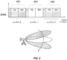
また、NRでは、アナログ、ハイブリッド、デジタルという異なるアンテナアーキテクチャをサポートする必要があることも知られている。これは、特にアナログ/ハイブリッドビームフォーミングの場合に、同時にいくつの方向をカバーできるかという点でいくつかの制限を意味する。所与の送信点(TRP)/アクセスノード/アンテナアレイにおいて良好なビーム方向を見つけるために、ビーム掃引手順が通常用いられる。ビーム掃引手順の典型的な例は、同期信号および/またはビーム識別信号を含むビームを、いくつかの可能な方向のそれぞれにおいて、一度に1つまたは少数の方向に向けることである。これは図3に示されており、図示されている各ローブはビームを表しており、ビームは連続的に、掃引方式で、または同時に、または何らかの組み合わせで送信され得る。同じカバレッジ特性が各ビーム内の同期信号とビーム識別信号の両方に適用される場合、UEはTRPに同期するだけでなく、所与の位置で最良のビーム知識を得ることもできる。 It is also known that NR needs to support different antenna architectures: analog, hybrid and digital. This means some limitations in terms of how many directions can be covered at the same time, especially in the case of analog / hybrid beamforming. A beam sweep procedure is commonly used to find a good beam direction at a given transmit point (TRP) / access node / antenna array. A typical example of a beam sweeping procedure is to direct a beam containing a sync signal and / or a beam identification signal in one or a few directions at a time, in each of several possible directions. This is shown in FIG. 3, where each lobe illustrated represents a beam, which can be transmitted continuously, in a sweeping manner, simultaneously, or in any combination. If the same coverage characteristics are applied to both the sync signal and the beam identification signal within each beam, the UE can not only synchronize to the TRP, but also get the best beam knowledge at a given position.
上述したように、LTEにおける共通信号およびチャネルは全方向的に、すなわちビームフォーミングなしに送信される。NRでは、基地局で多数のアンテナが利用可能であり、それらをビームフォーミング信号およびチャネルに組み合わせることができる様々な方法があるため、LTEで行われているように、この仮定はもはや有効ではないかもしれない。NRビームフォーミングのその設計原理の主な結果は、LTEにおいてはCRCの品質がPDCCHの品質を推定するために使用され得ることは明らかであるが、NRにおいて、チャネルおよび基準信号が異なる方法のためにこれは不明確になることである。言い換えれば、PDCCHが送信されるのと同じ方法で任意の特定の基準信号が送信されることを一般事項として想定することはできない。UEの観点から見たこの曖昧さは、基準信号とチャネルがネットワークによって異なる種類のビームフォーミング方式を介して送信されることができるという事実によるものであり、それは典型的にはリアルタイムネットワーク要件に基づいて決定される。これらの要件は、例えば、基準信号対制御チャネルによる無線オーバーヘッドに対する異なる許容レベル、または基準信号対制御チャネルに対する異なるカバレッジ要件を含み得る。 As mentioned above, common signals and channels in LTE are transmitted in all directions, i.e. without beamforming. In NR, this assumption is no longer valid, as is done in LTE, as many antennas are available at the base station and there are various ways in which they can be combined with beamforming signals and channels. Maybe. The main result of its design principle of NR beamforming is that in LTE it is clear that the quality of CRC can be used to estimate the quality of PDCCH, but in NR because of the different methods of channels and reference signals. This is to be unclear. In other words, it cannot be assumed as a general matter that any particular reference signal is transmitted in the same way that the PDCCH is transmitted. This ambiguity from the UE's point of view is due to the fact that reference signals and channels can be transmitted via different types of beamforming schemes depending on the network, which is typically based on real-time network requirements. Will be decided. These requirements may include, for example, different tolerance levels for radio overhead by the reference signal vs. control channel, or different coverage requirements for the reference signal vs. control channel.
NR設計原理からのこれらの課題にもかかわらず、接続モードのNR UEは、そのセル品質がまだ十分に良好であるかどうかを検証するために依然としてRLMを実行する必要があり、その結果UEはネットワークによって到達できる。そうでなければ、より高いレイヤに通知されるべきであり、そしてUEの自律的な行動が引き起こされるべきである。 Despite these challenges from the NR design principle, the NR UE in connected mode still needs to run RLM to verify if its cell quality is still good enough, and as a result the UE Reachable by network. If not, higher layers should be notified, and UE autonomous behavior should be triggered.
[NRにおけるモビリティ基準信号3GPPの合意]
3GPPの議論では、モビリティに関連する測定(例えば、ハンドオーバ、またはHO)のためにNRでUEによって使用されるモビリティ基準信号(MRS)について、いくつかの態様が合意されている。無線リソース制御(RRC)およびビームを含むRRC_CONNECTEDモードにおけるダウンリンクベースのモビリティについて、UEは少なくとも1つ以上の個々のビームを測定し、gNB(NR基地局に関する3GPP用語)はHOを実行するためにそれらのビームを考慮するメカニズムを有するべきである。これは、少なくともgNB間ハンドオーバをトリガし、HOピンポン/HO障害を回避するために必要である。UEが複数のビームの個々の品質および/または組み合わせた品質を報告するかどうかが決定されるべきである。UEはまた、アクティブモビリティにおける無線リソース管理(RRM)測定のために、そのサービングセルからのビームと非サービングセルからのビームとを区別することができなければならない。UEは、ビームがそのサービングセルからのものであるかどうかを判定できなければならない。サービング/非サービングセルが「サービング/非サービングビームセット」と称され得るかどうか、UEが個別シグナリングを介して通知されるか、または何らかのブロードキャスト信号に基づいてUEによって暗黙的に検出されるか、接続中のセルがアイドル状態のセルとどのように関連しているか、および個々のビームからの測定値に基づいてセル品質をどのように導出すどうかはまだ決定されていない。
[Agreement on mobility reference signal 3GPP in NR]
In the 3GPP discussion, several aspects have been agreed for the mobility reference signal (MRS) used by the UE in the NR for mobility-related measurements (eg, handover, or HO). For downlink-based mobility in RRC_CONNECTED mode, including radio resource control (RRC) and beams, the UE measures at least one individual beam and the gNB (3GPP term for NR base stations) is to perform HO. There should be a mechanism to consider those beams. This is necessary at least to trigger inter-gNB handover and avoid HO ping pong / HO failures. It should be determined whether the UE reports individual or / or combined quality of multiple beams. The UE must also be able to distinguish between beams from its serving cells and beams from non-serving cells for radio resource management (RRM) measurements in active mobility. The UE must be able to determine if the beam is from its serving cell. Whether serving / non-serving cells can be referred to as a "serving / non-serving beam set", the UE is notified via individual signaling, or implicitly detected by the UE based on some broadcast signal, or connected. It has not yet been determined how the cells inside relate to idle cells and how cell quality is derived based on measurements from individual beams.
MRSの特定の設計に対する複数のソリューションが検討されているが、これらのいずれにおいても、UEは、1組のMRSを介してそのサービングセル内でRRM測定を実行する。UEは、そのサービングセルに属する特定のMRSを知っているので、UEが検出し得る他のすべての基準信号は隣接していると仮定される。 Multiple solutions for a particular design of the MRS are being considered, in which case the UE performs RRM measurements within its serving cell via a set of MRSs. Since the UE knows the particular MRS that belongs to its serving cell, it is assumed that all other reference signals that the UE can detect are adjacent.
MRSのような基準信号に対する送信ストラテジーは、時間および/または周波数における自由度および/またはコード/シーケンス次元における自由度を利用することができる。直交リソースにおいて異なるビームのための基準信号を送信することによって、ネットワークは、直交基準信号に対応するUEからこれらの信号に対応する別個の測定報告を得ることができる。 Transmission strategies for reference signals such as MRS can take advantage of degrees of freedom in time and / or frequency and / or degrees of freedom in the code / sequence dimension. By transmitting reference signals for different beams in the orthogonal resource, the network can obtain separate measurement reports corresponding to these signals from the UE corresponding to the orthogonal reference signals.
上述したように、LTEにおけるRLMはCRSがベースであり、ここで広帯域信号は全てのサブフレームにおいて送信される。NRにおけるRLM設計に関するリーンデザイン原理の主な結果は、全てのサブフレームにおいて送信される広帯域信号のデザインを回避したいという願望があるということである。したがって、リーンデザインでは、NRにおけるRLMとに同じLTEソリューションを使用することは禁止される。 As mentioned above, RLM in LTE is based on CRS, where wideband signals are transmitted in all subframes. The main result of the lean design principle for RLM design in NR is the desire to avoid the design of wideband signals transmitted in all subframes. Therefore, lean design prohibits the use of the same LTE solution for RLM in NR.
以下に詳細に説明されるのは、セルがリーンデザインでビームフォーミング方式で信号を送信している場合、すなわち全帯域で、かつ、すべてのサブフレームにわたって送信される常時参照信号なしで、無線デバイス(例えばUE)がそのサービングセル品質を測定できる技術である。 Described in detail below are wireless devices when the cell is beamforming in a lean design, i.e., in all bands and without a constant reference signal transmitted over all subframes. A technology that allows (eg, UE) to measure its serving cell quality.
いくつかの実施形態によれば、ユーザ装置(UE)における方法は、一連のサブフレームを有するダウンリンク信号において、複数のサブフレームのそれぞれにおけるビームフォーミングされた基準信号を受信することを含み、当該ビームフォーミングされた基準信号は、ダウンリンク信号のすべてのサブフレームより少ないサブフレームで受信される。この方法はまた、受信されたビームフォーミングされた基準信号の少なくとも第1のサブセットを使用してモビリティ管理測定を実行することを含み、第1のサブセットは第1の周波数または第1の局所的範囲の周波数に対応する。方法は更に、受信されたビームフォーミングされた基準信号の第2のサブセットを使用してRLMを実行することを含む。第2のサブセットは、第1のサブセットと少なくとも部分的に異なり、第2の周波数または第2の局所的範囲の周波数に対応するビームフォーミングされた基準信号を含む。第2の周波数または第2の局所的範囲の周波数は、第1の周波数または第1の局所的範囲の周波数とは間隔をあけて離れていて異なる。ダウンリンク信号の一連のサブフレームは、1つ以上の制御チャネルを搬送し得る。 According to some embodiments, the method in the user apparatus (UE) comprises receiving a beam-formed reference signal in each of a plurality of subframes in a downlink signal having a series of subframes. The beam-formed reference signal is received in fewer subframes than all subframes of the downlink signal. The method also includes performing mobility management measurements using at least a first subset of the received beamformed reference signal, where the first subset is the first frequency or the first local range. Corresponds to the frequency of. The method further comprises performing an RLM using a second subset of the received beamformed reference signal. The second subset is at least partially different from the first subset and includes a beamformed reference signal corresponding to a second frequency or a frequency in a second local range. The frequency of the second frequency or the second local range differs from the frequency of the first frequency or the frequency of the first local range at intervals. A series of subframes of a downlink signal may carry one or more control channels.
いくつかの実施形態によれば、無線通信システムのアクセスノードにおける方法は、複数のサブフレームの各々において、ビームフォーミングされた基準信号を、搬送する一連のサブフレームを有する第1のダウンリンク信号において送信することを含み、当該ビームフォーミングされた基準信号は、ダウンリンク信号のすべてのサブフレームより少ないサブフレームで送信される。第1のサブセットは、第1の周波数または第1の局所的範囲の周波数に対応するビームフォーミングされた基準信号を含み、第2のサブセットは、第2の周波数または第2の局所的範囲の周波数に対応するビームフォーミングされた基準信号を含む。第2の周波数または第2の局所的範囲の周波数は、第1の周波数または第1の局所的範囲の周波数と間隔をあけて離れていて異なる。方法はまた、ビームフォーミングされた基準信号の少なくとも第1のサブセットを使用してモビリティ管理測定を実行し、ビームフォーミングされた基準信号の少なくとも第2のサブセットを使用してRLMを実行するようにUEを構成することを含む。いくつかの実施形態では、この構成は送信の前に行われる。いくつかの実施形態では、送信することは、ビームフォーミングされた基準信号を送信するために使用されたものと同じビームフォーミングパラメータを使用して第1の制御チャネルを送信することを含み得る。 According to some embodiments, the method in the access node of a wireless communication system is in a first downlink signal having a series of subframes carrying a beam-formed reference signal in each of a plurality of subframes. The beam-formed reference signal, including transmission, is transmitted in fewer subframes than all subframes of the downlink signal. The first subset contains beamformed reference signals corresponding to the first frequency or the frequency of the first local range, and the second subset is the frequency of the second frequency or the second local range. Includes a beamformed reference signal corresponding to. The frequency of the second frequency or the second local range differs from the frequency of the first frequency or the frequency of the first local range at intervals. The method also performs a mobility management measurement using at least the first subset of beamformed reference signals and UE to perform RLM using at least a second subset of beamformed reference signals. Includes configuring. In some embodiments, this configuration is done prior to transmission. In some embodiments, transmitting may include transmitting a first control channel using the same beamforming parameters that were used to transmit the beamformed reference signal.
いくつかの実施形態によれば、無線通信システムにおける動作のために構成されたUEは、送受信器回路と、当該送受信器回路に関連付けられて動作する処理回路とを有する。処理回路は、一連のサブフレームを有するダウンリンク信号において、複数のサブフレームのそれぞれにおけるビームフォーミングされた基準信号を受信するように構成され、ここで、ビームフォーミングされた基準信号は、ダウンリンク信号のすべてのサブフレームより少ないサブフレームで受信される。処理回路はまた、受信されたビームフォーミングされた基準信号の少なくとも第1のサブセットを使用してモビリティ管理測定を実行するように構成され、第1のサブセットは第1の周波数または第1の局所的範囲の周波数に対応する。処理回路はまた、受信されたビームフォーミングされた基準信号の第2のサブセットを使用してRLMを実行するように構成される。第2のサブセットは、第1のサブセットと少なくとも部分的に異なり、第2の周波数または第2の局所的範囲の周波数に対応するビームフォーミングされた基準信号を含む。第2の周波数または第2の局所的範囲の周波数は、第1の周波数または第1の局所的範囲の周波数と間隔をあけて離れていて異なる。 According to some embodiments, a UE configured for operation in a wireless communication system has a transmitter / receiver circuit and a processing circuit that operates in association with the transmitter / receiver circuit. The processing circuit is configured to receive a beamformed reference signal in each of a plurality of subframes in a downlink signal having a series of subframes, wherein the beamformed reference signal is a downlink signal. Received in fewer subframes than all subframes in. The processing circuit is also configured to perform mobility management measurements using at least the first subset of the received beamformed reference signal, the first subset being the first frequency or the first local. Corresponds to frequencies in the range. The processing circuit is also configured to perform RLM using a second subset of the received beamformed reference signal. The second subset is at least partially different from the first subset and includes a beamformed reference signal corresponding to a second frequency or a frequency in a second local range. The frequency of the second frequency or the second local range differs from the frequency of the first frequency or the frequency of the first local range at intervals.
いくつかの実施形態によれば、無線通信システムのアクセスノードは、送受信器回路と、当該送受信器回路に関連付けられて動作する処理回路とを有する。処理回路は、一連のサブフレームを有するダウンリンク信号において、複数のサブフレームのそれぞれにおけるビームフォーミングされた基準信号を送信するように構成され、ここで、ビームフォーミングされた基準信号は、ダウンリンク信号のすべてのサブフレームより少ないサブフレームで送信される。ビームフォーミングされた基準信号は第1のサブセットまたは少なくとも部分的に異なる第2のサブセットを含み、第1のサブセットは、第1の周波数または第1の局所的範囲の周波数に対応するビームフォーミングされた基準信号を含み、第2のサブセットは、第2の周波数または第2の局所的範囲の周波数に対応するビームフォーミングされた基準信号を含む。第2の周波数または第2の局所的範囲の周波数は、第1の周波数または第1の局所的範囲の周波数と間隔をあけて離れていて異なる。処理回路はまた、ビームフォーミングされた基準信号の少なくとも第1のサブセットを使用してモビリティ管理測定を実行し、ビームフォーミングされた基準信号の少なくとも第2のサブセットを使用してRLMを実行するようにUEを構成するように構成される。いくつかの実施形態では、処理回路は更に、ビームフォーミングされた基準信号を送信するために使用されたものと同じビームフォーミングパラメータを使用して第1の制御チャネルを送信するように構成される。 According to some embodiments, the access node of the wireless communication system has a transmitter / receiver circuit and a processing circuit that operates in association with the transmitter / receiver circuit. The processing circuit is configured to transmit a beamformed reference signal in each of a plurality of subframes in a downlink signal having a series of subframes, wherein the beamformed reference signal is a downlink signal. Sent in fewer subframes than all subframes in. The beam-formed reference signal includes a first subset or at least a partially different second subset, the first subset being beam-formed corresponding to a first frequency or a frequency in the first local range. The reference signal is included, and the second subset includes a beam-formed reference signal corresponding to a second frequency or a frequency in a second local range. The frequency of the second frequency or the second local range differs from the frequency of the first frequency or the frequency of the first local range at intervals. The processing circuit will also use at least a first subset of beamformed reference signals to perform mobility management measurements and use at least a second subset of beamformed reference signals to perform RLM. It is configured to configure the UE. In some embodiments, the processing circuit is further configured to transmit the first control channel using the same beamforming parameters that were used to transmit the beamformed reference signal.
本発明の更なる態様は、上に要約された方法、ならびに上に要約された装置およびUEの機能的実装に対応する装置、コンピュータプログラム製品、またはコンピュータ可読記憶媒体を対象とする。 A further aspect of the invention is directed to the methods summarized above, as well as devices, computer program products, or computer readable storage media that correspond to the functional implementation of the devices and UEs summarized above.
本明細書で開示される実施形態の利点は、より多くの周波数リソースに渡ってモビリティ管理に使用される参照信号(すなわちMRS)を送信することによって大きなオーバーヘッドを作り出すことよりもむしろ、RLM周期性要件がモビリティ要件よりも大きくなり得るため、MRSはMRSよりもまばらに送信され、オーバーヘッドおよび/または静的干渉をさらに低減する。セル内にアクティブなUEが存在しなくなると、これをオフにすることができる。ネットワークはまた、専用の静的/常時オンのRSをネットワークに導入することなく、UEが広範囲の時間−周波数リソースに渡って正確なRLM測定を行うことができることを保証することができる。 The advantage of the embodiments disclosed herein is RLM periodicity, rather than creating significant overhead by transmitting a reference signal (ie, MRS) used for mobility management over more frequency resources. Since the requirements can be larger than the mobility requirements, the MRS is transmitted more sparsely than the MRS, further reducing overhead and / or static interference. It can be turned off when there are no more active UEs in the cell. The network can also ensure that the UE can make accurate RLM measurements over a wide range of time-frequency resources without introducing a dedicated static / always-on RS into the network.
追加の利点としては、特にデータの非アクティブ時に、RLM測定の精度を犠牲にすることなくシグナリングオーバーヘッドを低レベルに維持できることが挙げられる。これは、5G NRでは非常に重要な要件である。高い搬送波周波数でのカバレッジを改善するために狭いUE固有のビームで制御チャネルを送信することが不可欠であるため、ネットワークは、より広いビームにフォールバックすることなく、RLM機能を制御チャネル設計で確実に維持できることを保証できる。 An additional advantage is that the signaling overhead can be maintained at a low level without sacrificing the accuracy of the RLM measurement, especially when the data is inactive. This is a very important requirement for 5G NR. Since it is essential to transmit the control channel with a narrow UE-specific beam to improve coverage at high carrier frequencies, the network ensures RLM functionality in the control channel design without falling back to the wider beam. Can be guaranteed to be maintained.
もちろん、本発明は上記の特徴および利点に限定されない。当業者は、以下の詳細な説明を読み、添付の図面を見れば、更なる特徴および利点を認識するであろう。 Of course, the present invention is not limited to the above features and advantages. Those skilled in the art will recognize further features and advantages by reading the detailed description below and looking at the accompanying drawings.
例示的なシステムは、UEとネットワーク無線アクセスノードを含み得る。ここで、無線デバイス、すなわちUEは、接続モード(コネクティッドモード)モビリティ(MRS)をサポートするように構成された同じ周期的基準信号に基づいてRRM測定を実行することによってビームフォーミングを伴うシステムにおいてRLMを実行する。 An exemplary system may include a UE and a network radio access node. Here, the wireless device, or UE, in a system with beamforming by performing RRM measurements based on the same periodic reference signal configured to support Connected Mode Mobility (MRS). Run RLM.
本開示の文脈では、「RLMを実行する」とは、RRM測定を実行し、所与のメトリック、例えば信号対干渉雑音比(SINR)の値を、制御チャネルが同じ方法で、すなわち類似のビームフォーミング特性および/または類似または代表的な周波数リソースを用いて送信されたであろうという仮定の下でのダウンリンク制御チャネル品質を表す閾値と比較することを意味する。 In the context of the present disclosure, "performing RLM" means performing an RRM measurement and applying a given metric, eg, a signal-to-noise ratio (SINR) value, in the same way that the control channels are, i.e. similar beams. Means to compare with a threshold representing downlink control channel quality under the assumption that it would have been transmitted with forming characteristics and / or similar or representative frequency resources.
RLMに使用されるRSの測定(値)は、異なるRSを使用してダウンリンク制御チャネルを推定し、制御情報を復号することができるという事実にもかかわらず、ネットワークが(例えば、スケジューリング情報を送信することによって)UEにコンタクトすると想定されるダウンリンク(DL)制御チャネル(例えば、LTEにおけるPDCCHまたはePDCCH)の品質と相関すべきである。例えば、PDCCHの復号化がUE固有の復調RS(DMRS)を使用して行われている間、UEは同じMRSを使用してRLMを実行することができる。本システムの1つの態様は、ネットワークがサービングセルMRSの品質とダウンリンク制御チャネルの品質との相関関係を保証することである。これは、そのUEに対して構成されたMRSを送信するために使用されたのと同じビームフォーミング構成(例えば、方向、ビーム幅、電力分布、同じアンテナパネルなど)を用いてダウンリンク制御チャネル情報をビームフォーミングすることによってネットワーク側で行うことができる。本明細書で使用されるように、用語「MRS」および「モビリティ基準信号」は、接続モードモビリティをサポートするように構成され、および/または接続モードモビリティをサポートするために、すなわち、いつ他のビームおよび/またはセルへハンドオーバするかを決定するためにUEによる測定のために使用される基準信号を指すために使用される。当然のことながら、これらの基準信号の一部または全部は他の目的にも使用されてもよく、これらの基準信号は他の名称で知られていてもよい。 The RS measurements (values) used for LTE are such that the network (eg, scheduling information) can be used to estimate downlink control channels and decode control information using different RSs. It should correlate with the quality of the downlink (DL) control channel (eg, PDCCH or ePDCCH in LTE) that is expected to contact the UE (by transmitting). For example, the UE can perform RLM using the same MRS while the PDCCH decoding is done using the UE-specific demodulation RS (DMRS). One aspect of the system is that the network guarantees a correlation between the quality of the serving cell MRS and the quality of the downlink control channel. It uses the same beamforming configuration (eg, direction, beamwidth, power distribution, same antenna panel, etc.) that was used to send the configured MRS to that UE for downlink control channel information. Can be done on the network side by beamforming. As used herein, the terms "MRS" and "mobility reference signal" are configured to support connected mode mobility and / or to support connected mode mobility, i.e., at any other time. Used to refer to a reference signal used for measurement by the UE to determine whether to hand over to the beam and / or cell. Of course, some or all of these reference signals may also be used for other purposes, and these reference signals may be known by other names.
1つ以上のビームで送信されたMRSの場合、異なる実施形態は、信号が搬送する情報を、例えば識別子に関して、様々な方法で定義することができる。いくつかの実施形態では、例えば、異なるRSが各ビームで送信され、各RSはそれ自身のビーム識別子(BID)を運ぶ。この場合、基準信号はビーム固有RS(BRS)と呼ぶことができ、UEはビーム毎に、すなわち、品質メトリック、例えば、個々のビーム毎のその特定のビームにおけるダウンリンク制御チャネルの送信品質に等しいRSRP、を測定することでRLMを実行することができる。他の実施形態では、同じRSが各ビームで送信されてもよく、各RSは同じ識別子を搬送する。この識別子は、BID、セル識別子セルID(CID)とすることができるグループ識別子、またはビームID+セルIDの両方とすることができる。これらの実施形態では、UEは、時間領域でビームを区別すること、および/または同じ識別子を搬送するビームにわたって単に平均化を実行することができる。 For MRS transmitted by one or more beams, different embodiments can define the information carried by the signal in various ways, eg, with respect to an identifier. In some embodiments, for example, different RSs are transmitted on each beam, and each RS carries its own beam identifier (BID). In this case, the reference signal can be referred to as the beam-specific RS (BRS), and the UE is equal to the transmission quality of the downlink control channel on a beam-by-beam basis, i.e., a quality metric, eg, an individual beam on that particular beam. RLM can be performed by measuring RSRP. In other embodiments, the same RS may be transmitted on each beam, and each RS carries the same identifier. This identifier can be both a BID, a group identifier that can be a cell identifier cell ID (CID), or a beam ID + cell ID. In these embodiments, the UE can distinguish beams in the time domain and / or simply perform averaging across beams carrying the same identifier.
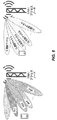
図6は、本明細書に記載のRLM手順を容易にする基準信号送信の原理を示す。図6の左側に見られるように、各ビームはモビリティの目的のために無線デバイス(例えば、UE)に対して構成されているRSを搬送する。これらの参照信号は、本明細書ではモビリティ参照信号またはMRSと呼ばれるが、それらは必ずしもその名前を持っていなくてもよい。「UEに対して構成された」とは、サービングセル/ビーム信号および/または非サービングセル/ビーム信号に関して、RRC_CONNECTEDモードのUEに測定および報告条件に関する情報が提供されることを意味する。これらのRSは、様々な実施形態において、BID、ビームIDおよびグループID(例えばセルIDとして理解され得る)、または単にグループIDを搬送し得る。図6の右側に見られるように、ダウンリンク制御チャネル、例えば、PDCCHは、モビリティの目的のために使用されるRSと同じビームフォーミング特性を使用して送信される。これは、たとえ異なる時間に送信されたとしても、ダウンリンク制御チャネルをRSと「同じビーム」で送信することとして理解され得る。ダウンリンク制御チャネルは、チャネル推定およびチャネル復号化の目的で、異なるRSを搬送する(または関連付けることができる)ことに留意されたい。これらは、必ずしもそうとは限らないが、モビリティのために使用されるものとは完全に分離することができ、様々な実施形態では、セル固有、UE固有、および/またはビーム固有とすることができる。 FIG. 6 shows the principle of reference signal transmission that facilitates the RLM procedure described herein. As seen on the left side of FIG. 6, each beam carries an RS configured for a wireless device (eg, UE) for mobility purposes. These reference signals are referred to herein as mobility reference signals or MRSs, but they do not necessarily have to have that name. By "configured for the UE" is meant providing information about measurement and reporting conditions to the UE in RRC_CONNECTED mode with respect to serving cell / beam signals and / or non-serving cell / beam signals. In various embodiments, these RSs may carry a BID, a beam ID and a group ID (which can be understood as, for example, a cell ID), or simply a group ID. As seen on the right side of FIG. 6, the downlink control channel, eg, PDCCH, is transmitted using the same beamforming characteristics as the RS used for mobility purposes. This can be understood as transmitting the downlink control channel with the "same beam" as the RS, even if transmitted at different times. Note that the downlink control channel carries (or can be associated with) different RSs for channel estimation and channel decoding purposes. These can be completely separate from those used for mobility, but not necessarily, and in various embodiments can be cell-specific, UE-specific, and / or beam-specific. it can.
図6に示す手法を考えると、ダウンリンク制御チャネルはMRSと同じ方法でビームフォーミングされるので、RLMはMRS、すなわち複数のRS(RS−1〜RS−N)上で実行することができることが理解されよう。測定されたMRSの品質は、ダウンリンク制御チャネルの品質に直接対応するだろう。したがって、同期および同期外れ検出のための閾値は、LTEの場合と同じ方法で利用することができる。 Considering the method shown in FIG. 6, since the downlink control channel is beamformed in the same way as MRS, RLM can be executed on MRS, that is, a plurality of RSs (RS-1 to RS-N). Will be understood. The measured MRS quality will correspond directly to the quality of the downlink control channel. Therefore, the thresholds for synchronization and out-of-synchronization detection can be used in the same way as for LTE.
しかしながら、RRM測定の要件を満たすために、これらのMRSは狭帯域信号(例えば、6つの中央物理リソースブロック(PRB))であると想定されてきた。一方、ダウンリンク制御チャネルは、全帯域で(LTE PDCCHとして)送信されるか、または、局所的/分散的(LTE ePDCCHおよびNRにおけるダウンリンク制御チャネル設計として)送信されることができる。 However, in order to meet the requirements of RRM measurements, these MRSs have been assumed to be narrowband signals (eg, 6 central physical resource blocks (PRBs)). The downlink control channel, on the other hand, can be transmitted over the entire band (as LTE PDCCH) or locally / distributed (as a downlink control channel design in LTE ePDCCH and NR).
局所的ダウンリンク制御チャネルの場合、すなわち、制御チャネルが利用可能な帯域幅と比較して比較的狭い帯域幅内で送信され、無線チャネルの周波数選択性が重要ではない場合、システムは、品質がUEのためにダウンリンク制御チャネルが送信されるPRBの品質と相関しているいくつかの代表的な物理リソースブロック(PRB)でMRSを送信し得る。しかしながら、非局所的/分散的ダウンリンク制御チャネルの場合、すなわち、周波数ダイバーシティを利用するために、利用可能な帯域幅に渡って広がるリソース要素を使用して制御チャネルが送信される場合、その技術は、MRS帯域幅は限られた数のPRBに限定されるが、MRSに基づくダウンリンク制御チャネル品質推定の限られた精度があり得るように、UEのダウンリンク制御チャネル周波数ははるかに広い帯域幅に拡張し得るという意味でいくつかの不正確さを提供し得る。 In the case of a local downlink control channel, that is, if the control channel is transmitted within a relatively narrow bandwidth compared to the available bandwidth and the frequency selectivity of the radio channel is not important, the system will be of good quality. The MRS may be transmitted in several representative physical resource blocks (PRBs) that correlate with the quality of the PRB on which the downlink control channel is transmitted for the UE. However, in the case of non-local / distributed downlink control channels, that is, when the control channels are transmitted using resource elements that extend over the available bandwidth to take advantage of frequency diversity, the technique. Although the MRS bandwidth is limited to a limited number of PRBs, the UE's downlink control channel frequency is in a much wider band so that there may be limited accuracy in MRS-based downlink control channel quality estimation. It can provide some inaccuracy in the sense that it can be extended to width.
本発明の実施形態は、接続モードモビリティをサポートするように構成された同じ周期的基準信号(MRS)のバージョンであるが、所与のUEのダウンリンク制御チャネルと同じ周波数リソースにおいて周波数領域で繰り返されることが送信されるであろう新しい信号に基づいて、RRM測定を実行することによってビームフォーミングを伴うシステムにおいてUEがRLMを実行する技術を提供する。これらの複数のバージョンのモビリティRSはまた、いくつかの追加の時間領域ダイバーシティを提供するために、および/またはビームフォーミング送信を等価にすることを可能にするために、異なるサブフレームで送信され得る。 An embodiment of the invention is a version of the same periodic reference signal (MRS) configured to support connected mode mobility, but repeated in the frequency domain at the same frequency resource as the downlink control channel of a given UE. Provides a technique for a UE to perform an RLM in a system with beamforming by performing an RRM measurement based on a new signal that will be transmitted. These multiple versions of the Mobility RS can also be transmitted in different subframes to provide some additional time domain diversity and / or to allow beamforming transmissions to be equivalent. ..
例えば、方法は、(単一セットのリソースブロックの代わりに)UEのダウンリンク制御チャネルが送信されることになる周波数リソースに等しい複数の周波数リソースに渡って繰り返されるが、MRSの複数のレプリカに基づいてRLMを実行することを含む。ネットワーク側では、無線アクセスノードは、RLM目的のために再使用される基準信号を送信するのと同じ方法で、ダウンリンク制御チャネル情報を送信する。 For example, the method is repeated over multiple frequency resources equal to the frequency resource to which the UE's downlink control channel will be transmitted (instead of a single set of resource blocks), but to multiple replicas of the MRS. Includes performing RLM based on. On the network side, the wireless access node transmits downlink control channel information in the same way that it transmits a reference signal that is reused for RLM purposes.
以下では、本発明の例示的な実施形態による概念を、添付の図面を参照しながらより詳細に説明する。例示された実施形態は、以下ではUEとも呼ばれる、無線デバイスによって実行される、そのような無線通信ネットワークにおける無線リンクモニタリング、およびアクセスノードに関する。無線通信ネットワークは、例えば、LTE RATまたは3GPP New Radio(NR)の発展などの5G無線アクセス技術(RAT)に基づき得る。しかしながら、図示の概念は他のRATにも適用可能であることを理解されたい。 Hereinafter, the concept according to an exemplary embodiment of the present invention will be described in more detail with reference to the accompanying drawings. Illustrated embodiments relate to wireless link monitoring and access nodes in such wireless communication networks performed by wireless devices, also referred to below as UEs. The wireless communication network may be based on 5G wireless access technology (RAT), such as, for example, the development of LTE RAT or 3GPP New Radio (NR). However, it should be understood that the illustrated concept is applicable to other RATs.
図7は、開示された技術のうちの1つ以上を実行するように構成され得るネットワークノード30の図を示す。ネットワークノード30は、基地局、無線基地局、無線基地局、発展型ノードB(eNodeB)、ノードB、gNodeB、または中継ノードなどのネットワークアクセスノードを含むことができる任意の種類のネットワークノードとすることができる。以下に記載される非限定的な実施形態では、ネットワークノード30は、NRネットワークにおいてセルラーネットワークアクセスノードとして動作するように構成されているとして説明される。
FIG. 7 shows a diagram of a
当業者であれば、例えば処理回路32による実行のための適切なプログラム命令の修正および/または追加を通じて、本明細書に記載の方法およびシグナリングプロセスのうちの1つ以上を実行するために各タイプのノードをどのように適合させるかを容易に理解するだろう。 One of ordinary skill in the art would use each type to perform one or more of the methods and signaling processes described herein, eg, through modification and / or addition of appropriate program instructions for execution by the processing circuit 32. You will easily understand how to fit the nodes in.
ネットワークノード30は、無線端末、他のネットワークアクセスノードおよび/またはコアネットワーク間の通信を容易にする。ネットワークノード30は、データおよび/またはセルラー通信サービスを提供する目的で、コアネットワーク内の他のノード、無線ノード、および/またはネットワーク内の他のタイプのノードと通信するための回路を含む通信インターフェース回路38を含み得る。ネットワークノード30は、アンテナ34および送受信器回路36を使用してUEと通信する。送受信器回路36は、セルラー通信サービスを提供する目的で、無線アクセス技術に従って信号を送受信するように集合的に構成された送信器回路、受信器回路、および関連する制御回路を含み得る。
The
ネットワークノード30はまた、送受信器回路36、および場合によっては通信インターフェース回路38と動作可能に関連付けられた1つ以上の処理回路32を含む。説明を容易にするために、1つ以上の処理回路32は、以後「処理回路(circuit)32」または「処理回路(circuitry)32」と呼ばれる。処理回路32は、1つ以上のマイクロプロセッサ、マイクロコントローラ、デジタル信号プロセッサ(DSP)、フィールドプログラマブルゲートアレイ(FPGA)、コンプレックスプログラマブルロジックデバイス(CPLD)、特定用途向け集積回路(ASIC)などの1つ以上のデジタルプロセッサ42、またはそれらの任意の組み合わせを備える。より一般的には、処理回路32は、固定回路、または本明細書に教示された機能を実施するプログラム命令の実行を介して特別に構成されたプログラム可能回路を含み得る。プロセッサ42は、マルチコア、すなわち、性能の向上、電力消費の低減、および複数タスクのより効率的な同時処理のために利用される2つ以上のプロセッサコアを有し得る。
The
処理回路32はまた、メモリ44を有する。いくつかの実施形態では、メモリ64は、1つ以上のコンピュータプログラム46、およびオプション的に設定データ48を格納する。メモリ44は、コンピュータプログラム46に非一時的な記憶装置を提供し、ディスク記憶装置、固体メモリ記憶装置、またはそれらの任意の組み合わせなどの1つ以上の種類のコンピュータ可読媒体を含み得る。ここで、「非一時的」とは、恒久的、半永久的、または少なくとも一時的に持続的な記憶を意味し、例えばプログラム実行のための不揮発性メモリへの長期記憶と作業メモリへの記憶の両方を包含する。非限定的な例として、メモリ44は、SRAM、DRAM、EEPROM、およびFLASHメモリのうちのいずれか1つ以上含み、これらは処理回路32内にあり、および/または処理回路32とは別個であり得る。一般に、メモリ44は、コンピュータプログラム46およびネットワークアクセスノード30によって使用される任意の構成データ48の非一時的記憶を提供する1つ以上の種類のコンピュータ可読記憶媒体を備える。処理回路32は、例えば、メモリ44に格納された適切なプログラムコードを使用することによって、以下に詳述される方法および/またはシグナリングプロセスのうちの1つ以上を実行するように構成され得る。
The processing circuit 32 also has a
いくつかの実施形態によれば、ネットワークノード30は、セルがビームフォーミング方式で信号を送信している場合に、UEがそのサービングセルの品質を測定することを可能にする無線通信システムのアクセスノードとして動作するように構成される。処理回路32は、一連のサブフレームを有するダウンリンク信号において、複数のサブフレームのそれぞれにおけるビームフォーミングされた基準信号を送信するように構成され、ここで、ビームフォーミングされた基準信号は、ダウンリンク信号のすべてのサブフレームより少ないサブフレームで送信される。ビームフォーミングされた基準信号は第1のサブセットまたは少なくとも部分的に異なる第2のサブセットを含む。ここで、第1のサブセットは、第1の周波数または第1の局所的範囲の周波数に対応するビームフォーミングされた基準信号を含み、第2のサブセットは、第2の周波数または第2の局所的範囲の周波数に対応するビームフォーミングされた基準信号を含む。「局所的範囲の周波数」とは、周波数範囲が利用可能な帯域幅の比較的小さい部分にすぎないことを意味し、その結果、周波数範囲全体に渡って無線チャネルにはわずかな周波数選択性しかない。第2の周波数または第2の局所的範囲の周波数は、第1の周波数または第1の局所的範囲の周波数と間隔をあけて離れていて異なる。処理回路32はまた、ビームフォーミングされた基準信号の少なくとも第1のサブセットを使用してモビリティ管理測定を実行し、ビームフォーミングされた基準信号の少なくとも第2のサブセットを使用してRLMを実行するようにUEを構成するように構成される。いくつかの実施形態では、処理回路32は、ビームフォーミングされた基準信号を送信するために使用されたものと同じビームフォーミングパラメータを使用して第1の制御チャネルを送信するように構成される。
According to some embodiments, the
物理的な実装にかかわらず、処理回路32は、いくつかの実施形態によれば、図8に示されるように、無線通信システムのアクセスノードにおいて方法800を実行するように構成される。方法800は、複数のサブフレームのそれぞれにおいて、ビームフォーミングされた基準信号を、搬送する一連のサブフレームを有する第1のダウンリンク信号において送信することを含み、ここでビームフォーミングされた基準信号は、ダウンリンク信号のすべてのサブフレームより少ないサブフレームにおいて送信される(ブロック804)。ビームフォーミングされた基準信号は第1のサブセットまたは少なくとも部分的に異なる第2のサブセットを含み、第1のサブセットは、第1の周波数または第1の局所的範囲の周波数に対応するビームフォーミングされた基準信号を含み、第2のサブセットは、第2の周波数または第2の局所的範囲の周波数に対応するビームフォーミングされた基準信号を含む。第2の周波数または第2の局所的範囲の周波数は、第1の周波数または第1の局所的範囲の周波数と間隔をあけて離れていて異なる。方法はまた、ビームフォーミングされた基準信号の少なくとも第1のサブセットを使用してモビリティ管理測定を実行し、ビームフォーミングされた基準信号の少なくとも第2のサブセットを使用してRLMを実行するようにUEを構成することを含む(ブロック802)。構成することは送信することの前に実行することができ、送信することは、ビームフォーミングされた基準信号を送信するために使用されたものと同じビームフォーミングパラメータを使用して第1の制御チャネルを送信することを含み得る。
Regardless of the physical implementation, the processing circuit 32 is configured to perform
第2の周波数または第2の局所的範囲の周波数に対応するビームフォーミングされた基準信号は、第1の周波数または第1の局所的範囲の周波数に対応するビームフォーミングされた基準信号の時間周期とは異なる時間周期を有することができる。第2のサブセットは更に、第1および第2の周波数または第1および第2の局所的範囲の周波数と間隔をあけて離れていて異なる第3の周波数または第3の局所的範囲の周波数に対応するビームフォーミングされた基準信号を含み得る。 The beamformed reference signal corresponding to the second frequency or the frequency of the second local range is the time period of the beamformed reference signal corresponding to the frequency of the first frequency or the first local range. Can have different time cycles. The second subset further corresponds to a third frequency or a third local range frequency that is spaced apart from the first and second frequencies or the frequencies of the first and second local ranges. Can include a beamformed reference signal.
いくつかの場合では、第1の周波数または第1の局所的範囲の周波数に対応するビームフォーミングされた基準信号は、それぞれ、第2の周波数または第2の局所的範囲の周波数に対応するビームフォーミングされた基準信号と時間的に一致し得る。 In some cases, the beamformed reference signal corresponding to the first frequency or the frequency of the first local range is beamformed corresponding to the second frequency or the frequency of the second local range, respectively. It can coincide with the reference signal given in time.
方法800は、第1の制御チャネルのためのチャネルを推定する際にUEによって使用するための1つ以上の追加の基準信号を送信すること、および/またはビームフォーミングされた基準信号を搬送する周波数リソースで少なくとも部分的に重なり合う周波数リソースで第1の制御チャネルを送信することを含み得る。ビームフォーミングされた基準信号は、第1のビームに対するビーム固有基準信号を含み得る。ビーム固有基準信号はビーム識別子を搬送することができ、方法800はビーム固有基準信号からビーム識別子を復号することを含むことができる。
いくつかの実施形態の別の態様は、ビームフォーミングされた基準信号が周期的、かつ、まばらに送信される、すなわちすべてのサブフレームで送信されるのではないことである。しかしながら、RLMに必要とされる周期性は、測定報告をトリガするためにRRM測定に必要とされる周期性とは異なり得る。したがって、いくつかの実施形態では、UEは、RLMのために送信されたRSからいくつかの特定のサンプルのみを選択することができ、これらのサンプル/サブフレームはおそらくネットワークによって構成されている。 Another aspect of some embodiments is that the beamformed reference signal is transmitted periodically and sparsely, i.e. not in all subframes. However, the periodicity required for RLM can differ from the periodicity required for RRM measurements to trigger a measurement report. Therefore, in some embodiments, the UE can select only some specific samples from the RS transmitted for the RLM, and these samples / subframes are probably configured by the network.
いくつかの場合では、例えば、UEは、ビームフォーミングされた基準信号の周期性で構成され、規格内の予め定義されたRLM周期性に基づいて、RLMについてRRM測定を実行する。他の場合では、UEは、両方の周期性、すなわち信号が送信される1つの周期性と、その間欠受信(DRX)サイクルに一致するRLMに使用されるべき周期性とについて通知される。 In some cases, for example, the UE consists of the periodicity of the beamformed reference signal and performs RRM measurements on the RLM based on the predefined RLM periodicity within the standard. In other cases, the UE is informed of both periodicities, that is, one periodicity in which the signal is transmitted and the periodicity to be used for the RLM that matches its intermittent receive (DRX) cycle.
方法800は、ビームフォーミングされた基準信号の第1のサブセットについて周期性および/または周波数位置を定義する1つ以上の第1の構成パラメータをUEに送信することを含み得る。方法800は、ビームフォーミングされた基準信号の第2のサブセットについて周期性および/または周波数位置を定義する1つ以上の第2の構成パラメータをUEに送信することを含み得る。
図9は、無線デバイス50として示される対応するUEの図を示す。無線デバイス50は、セルラーネットワーク内のUEなどのネットワーク内で動作することができる任意の無線端末を表すと見なすことができる。他の例は、通信デバイス、ターゲットデバイス、デバイス・ツー・デバイス(D2D)UE、マシンタイプUE、またはマシンツーマシン通信(M2M)が可能なUE、UEを備えたセンサ、PDA(パーソナルデジタルアシスタント)、タブレット、携帯端末、スマートフォン、ラップトップ内蔵機器(LEE)、ラップトップ搭載機器(LME)、USBドングル、顧客宅内機器(CPE)等を含み得る。
FIG. 9 shows a diagram of a corresponding UE shown as
無線デバイス50は、アンテナ54および送受信器回路56を介してセルラーネットワーク内の無線ノードまたは基地局と通信するように構成されている。送受信器回路56は、セルラー通信サービスを使用する目的で、無線アクセス技術に従って信号を送受信するように集合的に構成された送信器回路、受信器回路、および関連する制御回路を含み得る。この説明では、この無線アクセス技術はNRである。
The
無線デバイス50はまた、無線送受信器回路56と動作可能に関連付けられた1つ以上の処理回路52を含む。処理回路52は、1つ以上のデジタル処理回路、例えば1つ以上のマイクロプロセッサ、マイクロコントローラ、DSP、FPGA、CPLD、ASIC、またはそれらの任意の組み合わせを備える。より一般的には、処理回路52は、固定回路、または本明細書に教示された機能を実施するプログラム命令の実行を介して特別に適合化されたプログラム可能回路を含み得る。処理回路52はマルチコアであり得る。
The
処理回路52はまた、メモリ64を有する。いくつかの実施形態では、メモリ64は、1つ以上のコンピュータプログラム66、およびオプション的に設定データ58を格納する。メモリ64は、コンピュータプログラム66に非一時的な記憶装置を提供し、ディスク記憶装置、固体メモリ記憶装置、またはそれらの任意の組み合わせなどの1つ以上の種類のコンピュータ可読媒体を含み得る。非限定的な例として、メモリ64は、SRAM、DRAM、EEPROM、およびFLASHメモリのうちのいずれか1つ以上含み、これらは処理回路52内にあり、および/または処理回路52とは別個であり得る。一般に、メモリ64は、コンピュータプログラム66およびユーザ装置50によって使用される任意の構成データ68の非一時的記憶を提供する1つ以上の種類のコンピュータ可読記憶媒体を備える。処理回路52は、例えば、メモリ64に格納された適切なプログラムコードを使用することによって、以下に詳述される方法および/またはシグナリングプロセスのうちの1つ以上を実行するように構成され得る。
The processing circuit 52 also has a
無線デバイスは、いくつかの実施形態によれば、セルがビームフォーミング方式で信号を送信している場合のサービングセルの品質を測定するように構成される。したがって、処理回路52は、一連のサブフレームを有するダウンリンク信号において、複数のサブフレームのそれぞれにおけるビームフォーミングされた基準信号を受信するように構成され、ここで、ビームフォーミングされた基準信号は、ダウンリンク信号のすべてのサブフレームより少ないサブフレームで受信される。処理回路52はまた、受信されたビームフォーミングされた基準信号の少なくとも第1のサブセットを使用してモビリティ管理測定を実行するように構成され、第1のサブセットは第1の周波数または第1の局所的範囲の周波数に対応する。処理回路52はまた、受信されたビームフォーミングされた基準信号の第2のサブセットを使用してRLMを実行するように構成され、第2のサブセットは第1のサブセットとは少なくとも部分的に異なり、第2の周波数または第2の局所的範囲の周波数に対応するビームフォーミングされた基準信号を含む。第2の周波数または第2の局所的範囲の周波数は、第1の周波数または第1の局所的範囲の周波数と間隔をあけて離れていて異なる。 The wireless device is configured to measure the quality of the serving cell when the cell is transmitting a signal in a beamforming manner, according to some embodiments. Therefore, the processing circuit 52 is configured to receive the beamformed reference signal in each of the plurality of subframes in the downlink signal having a series of subframes, and the beamformed reference signal is here. Received in fewer subframes than all subframes of the downlink signal. The processing circuit 52 is also configured to perform mobility management measurements using at least a first subset of the received beamformed reference signal, the first subset being the first frequency or the first local. Corresponds to frequencies in the target range. The processing circuit 52 is also configured to perform RLM using a second subset of received beamformed reference signals, the second subset being at least partially different from the first subset. Includes a beamformed reference signal corresponding to a second frequency or a frequency in a second local range. The frequency of the second frequency or the second local range differs from the frequency of the first frequency or the frequency of the first local range at intervals.
いくつかの実施形態によれば、図10に示すように、処理回路52は、一連のサブフレームを有するダウンリンク信号において、複数のサブフレームのそれぞれにおけるビームフォーミングされた基準信号を受信することを含む方法1000を実行するように構成され、当該ビームフォーミングされた基準信号は、ダウンリンク信号のすべてのサブフレームより少ないサブフレームで受信される(ブロック1002)。方法1000はまた、受信されたビームフォーミングされた基準信号の少なくとも第1のサブセットを使用してモビリティ管理測定を実行することを含み、第1のサブセットは第1の周波数または第1の局所的範囲の周波数に対応する(ブロック1004)。方法1000は更に、受信されたビームフォーミングされた基準信号の第2のサブセットを使用してRLMを実行することを含み、第2のサブセットは第1のサブセットとは少なくとも部分的に異なり、第2の周波数または第2の局所的範囲の周波数に対応するビームフォーミングされた基準信号を含む(ブロック1006)。第2の周波数または第2の局所的範囲の周波数は、第1の周波数または第1の局所的範囲の周波数と間隔をあけて離れていて異なる。
According to some embodiments, as shown in FIG. 10, the processing circuit 52 receives a beamformed reference signal at each of the plurality of subframes in a downlink signal having a series of subframes. The beamformed reference signal is configured to perform the including
いくつかの場合、第2の周波数または第2の局所的範囲の周波数に対応するビームフォーミングされた基準信号は、第1の周波数または第1の局所的範囲の周波数に対応するビームフォーミングされた基準信号の時間周期とは異なる時間周期を有する。第2のサブセットは、第1および第2の周波数または第1および第2の局所的範囲の周波数と間隔をあけて離れていて異なる第3の周波数または第3の局所的範囲の周波数に対応するビームフォーミングされた基準信号を含み得る。ビームフォーミングされた基準信号は、第2の周波数または第2の局所的範囲の周波数に対応するビームフォーミングされた基準信号とそれぞれ時間的に一致する第1の周波数または第1の局所的範囲の周波数に対応し得る。 In some cases, the beamformed reference signal corresponding to the second frequency or the frequency in the second local range is the beamformed reference signal corresponding to the frequency in the first frequency or the first local range. It has a time cycle different from the time cycle of the signal. The second subset corresponds to a third frequency or a frequency in the third local range that is spaced apart from the first and second frequencies or the frequencies in the first and second local ranges. It may include a beamformed reference signal. The beamformed reference signal is the frequency of the first frequency or the first local range that coincides with the beamformed reference signal corresponding to the second frequency or the frequency of the second local range, respectively. Can correspond to.
RLMを実行することは、メトリックを取得するために、同じビームフォーミングされた基準信号の少なくともいくつかを使用して1つ以上の測定を実行することと、メトリックを所定のダウンリンク制御チャネル品質を表す閾値と、制御チャネル品質に対応する仮想制御チャネルがビームフォーミングされた基準信号に適用された同じビームフォーミング特性を使用して送信されるという仮定の下で、比較することを含み得る。方法1000は、第1の制御チャネルに対するチャネルを推定するために1つ以上の追加の基準信号を使用して第1の制御チャネルを復調することを含む。第1の制御チャネルは、RLMを実行するために使用されるビームフォーミングされた基準信号を搬送する少なくとも部分的に重なり合う周波数リソースにおいて受信され得る。
Performing an RLM is to perform one or more measurements using at least some of the same beamformed reference signals to obtain the metric, and to obtain the metric with a given downlink control channel quality. Comparison may be included with the threshold represented and the assumption that the virtual control channel corresponding to the control channel quality is transmitted using the same beamforming characteristics applied to the beamformed reference signal.
RLMを実行することはまた、同じビームフォーミングされた基準信号の少なくともいくつかの測定値に基づいて、UEが同期状態または非同期状態であると決定することを含む。 Performing RLM also includes determining that the UE is in synchronous or asynchronous state based on at least some measurements of the same beamformed reference signal.
いくつかの場合では、同じビームフォーミングされた基準信号の少なくともいくつかは、第1のビームに対するビーム固有の基準信号を含み、RLMを実行することは、ビーム固有の基準信号を使用して第1のビームに対するRLMを実行することを含み得る。ビーム固有基準信号はビーム識別子を搬送することができ、方法1000はビーム固有基準信号からビーム識別子を復号することを含み得る。
In some cases, at least some of the same beamformed reference signals include a beam-specific reference signal for the first beam, and performing RLM is the first using the beam-specific reference signal. It may include performing an RLM on the beam of. The beam-specific reference signal can carry the beam identifier, and
方法1000はまた、当該モビリティ管理測定を実行する前に、ビームフォーミングされた基準信号の第1のサブセットについて周期性および/または周波数位置を定義する1つ以上の第1の構成パラメータを受信することを含み得る。方法1000は更に、当該RLMを実行する前に、ビームフォーミングされた基準信号の第2のサブセットについて周期性および/または周波数位置を定義する1つ以上の第2の構成パラメータを受信することを含み得る。
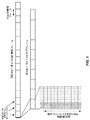
課題と解決策を記述する技術を更に説明する。図11に示す構成例に見られるように、モビリティに使用されるRSの送信は、時間および周波数領域において、RRMおよび同期機能に対してまばらに構成することができる。例えば、モビリティのために使用されるRSは、図11に示されるように、5つのサブフレームごとに6つの隣接するPRB上で送信されることができる。 The techniques for describing issues and solutions will be further described. As seen in the configuration example shown in FIG. 11, the transmission of RS used for mobility can be sparsely configured for RRM and synchronization functions in the time and frequency domain. For example, the RS used for mobility can be transmitted on six adjacent PRBs every five subframes, as shown in FIG.
しかしながら、サービングMRSセット内のMRSのそのような時間−周波数リソース粒度は、リソースグリッド上でPDCCHが発生するほど豊富ではない。RLM手順中の測定サンプル数は、ダウンリンク制御チャネルが送信される時間/周波数リソースの品質を捕捉するのに十分に大きくあるべきである。したがって、サンプルはダウンリンク送信帯域幅全体に渡って多くのサブキャリアで取得されるべきである。RLMのために使用されるサービス提供MRSの周波数割り当ては、ダウンリンク制御チャネルのための局所的または分散的方式に基づくことができる。局所方式は、より少ないUE計算を必要とし得るが、分散方式は、周波数選択的チャネルにおいてより良い精度を提供し得る。 However, such time-frequency resource grain size of MRS within the serving MRS set is not rich enough to cause PDCCH on the resource grid. The number of measurement samples during the RLM procedure should be large enough to capture the quality of the time / frequency resources transmitted by the downlink control channel. Therefore, samples should be taken with many subcarriers across the downlink transmit bandwidth. The frequency allocation of the service-providing MRS used for RLM can be based on local or decentralized schemes for downlink control channels. The local method may require less UE computation, while the distributed method may provide better accuracy in the frequency selective channel.
図11に示される例によって示唆されるように、RRM測定の要件を満たすために、モビリティRSは、狭帯域信号、例えば6つの中央のPRBのみを占有することが想定されている。一方、ダウンリンク制御チャネルは、全帯域で(LTE PDCCHの場合のように)送信されるか、または、局所的/分散的(LTE ePDCCHの場合のように)送信されることができる。 As suggested by the example shown in FIG. 11, the mobility RS is expected to occupy only a narrowband signal, eg, six central PRBs, to meet the requirements of RRM measurements. On the other hand, the downlink control channel can be transmitted over the entire band (as in the case of LTE PDCCH) or locally / distributed (as in the case of LTE ePDCCH).
局所化ダウンリンク制御チャネルの場合、MRSは、その品質がUEのダウンリンク制御が送信されるであろうPRBの品質と相関しているいくつかの代表的なPRBにおいて送信され得る。しかしながら、非局所化/分散化ダウンリンク制御チャネルの場合、MRS帯域幅が限られた数のPRBに限定される一方で、ダウンリンク制御チャネルの周波数割り当てがはるかに広い帯域幅に拡張しうるという意味で、本技術はいくつかの不正確さをもたらし得る。よって、比較的狭帯域のモビリティRSに基づくダウンリンク制御チャネル品質推定の限られた精度があり得る。 In the case of a localized downlink control channel, the MRS may be transmitted in some representative PRBs whose quality correlates with the quality of the PRB to which the downlink control of the UE will be transmitted. However, in the case of delocalized / decentralized downlink control channels, the MRS bandwidth is limited to a limited number of PRBs, while the frequency allocation of the downlink control channels can be extended to a much wider bandwidth. In a sense, the technology can introduce some inaccuracies. Therefore, there may be limited accuracy in downlink control channel quality estimation based on relatively narrow bandwidth mobility RS.
本明細書に開示される技術および装置の実施形態は、この問題に対処し、そしてUEおよびネットワーク無線アクセスノードにおける方法を含む。ここで、UEは、接続モードモビリティ(MRS)をサポートするように構成された同じ周期的基準信号のバージョンであるが周波数リソース内の周波数領域において繰り返される新しい信号に基づいてRRM測定を実行することによってビームフォーミングを伴うシステムにおいてRLMを実行する。所与のUEのダウンリンク制御チャネルが送信されるだろう。これらの複数のバージョンのMRSはまた、いくつかの追加の時間領域ダイバーシティを提供するために、および/またはビームフォーミング送信を等価にすることを可能にするために、異なるサブフレームで送信され得る。 Embodiments of the techniques and devices disclosed herein address this issue and include methods in UEs and network radio access nodes. Here, the UE performs RRM measurements based on a new signal that is a version of the same periodic reference signal configured to support Connected Mode Mobility (MRS) but is repeated in the frequency domain within the frequency resource. Performs RLM in a system with beamforming. The downlink control channel for a given UE will be transmitted. These multiple versions of the MRS may also be transmitted in different subframes to provide some additional time domain diversity and / or to allow beamforming transmissions to be equivalent.
このアプローチの1つの利点は、はるかに多くの周波数リソース上でMRSを送信することによって大きなオーバーヘッドを生成する代わりに、このアプローチは、RLM周期性要件がモビリティ要件よりも大きいという事実を活用することである。したがって、MRSのレプリカバージョンは、MRSよりも時間および周波数領域においてよりまばらに送信され、RSによって引き起こされるオーバーヘッドおよび/または静的干渉を低減する。別の利点は、セル内にアクティブなUEが存在しなくなると、RLM目的のためだけに使用されるレプリカRSをオフにすることができることである。全体として、このアプローチは、静的/常時オンの周期的なRSをネットワークに導入することなく、UEが広範囲の時間−周波数リソースに渡って正確なRLM測定を行うことができることを保証する。 One advantage of this approach is that instead of generating significant overhead by transmitting MRS over far more frequency resources, this approach takes advantage of the fact that the RLM periodicity requirement is greater than the mobility requirement. Is. Therefore, replica versions of MRS are transmitted more sparsely in the time and frequency domain than MRS, reducing overhead and / or static interference caused by RS. Another advantage is that replica RS, which is used solely for RLM purposes, can be turned off when there are no more active UEs in the cell. Overall, this approach ensures that UEs can make accurate RLM measurements over a wide range of time-frequency resources without introducing static / always-on periodic RS into the network.
他の利点は、特にデータの非アクティブ時にRLM測定の精度を犠牲にすることなく、シグナリングオーバーヘッドを低レベルに維持されることである。これは、5G NRでは重要な要件であると予測される。更に、これらの技術は、ダウンリンク制御チャネルの周波数割り当てがMRSに対して定義されたものよりも広い帯域幅に渡って拡張されるときにも正確なRLMを提供する。 Another advantage is that the signaling overhead is maintained at a low level, especially when the data is inactive, without sacrificing the accuracy of the RLM measurement. This is expected to be an important requirement for 5G NR. In addition, these techniques provide accurate RLM even when the frequency allocation of the downlink control channel is extended over a wider bandwidth than that defined for the MRS.
次に、本開示の技術によれば、無線デバイス(例えば、UE)は、単一のリソースブロックの局所的セットだけを使用するのではなく、間隔をあけて複数の周波数リソースに渡って分散されたRSを使用してRLMのRRM測定を実行する。これをサポートするために、いくつかの実施形態におけるUEは、同じタイプのRSについて2つのタイプの構成を提供される。これは、例えば無線リソース構成(RRC)プロトコルを使用して、例えばRRC接続再構成メッセージを介して行われ得る。第1に、UEは、MRSが周期性T_mobilityで送信されるPRB等の周波数リソースと、これらが送信されるサブフレーム等の時間領域リソースとを指定するモビリティ構成を提供される。その後、UEは、モビリティの目的で必要に応じてこれらのリソースのMRSを測定できる。第2に、UEは、MRSが周期性T_RLMで送信される追加のPRB等の周波数リソースと、これらの追加のMRSが送信されるサブフレーム等の時間領域リソースとを指定するRLM構成を提供される。それから、UEはこれらの追加の時間周波数リソース(およびモビリティ設定で指定されたリソース)に含まれるMRSの一部または全部をRLM目的で使用できる。 Second, according to the techniques of the present disclosure, wireless devices (eg, UEs) are not only using a local set of single resource blocks, but are distributed across multiple frequency resources at intervals. RRM measurement of RLM is performed using RS. To support this, UEs in some embodiments are provided with two types of configurations for the same type of RS. This can be done, for example, using the Radio Resource Configuration (RRC) protocol, eg via an RRC connection reconfiguration message. First, the UE is provided with a mobility configuration in which the MRS specifies a frequency resource such as a PRB transmitted in a periodic T_mobility and a time domain resource such as a subframe in which they are transmitted. The UE can then measure the MRS of these resources as needed for mobility purposes. Second, the UE is provided with an RLM configuration that specifies additional frequency resources such as PRBs through which the MRS is transmitted in periodic T_RLM and time domain resources such as subframes through which these additional MRS are transmitted. To. The UE can then use some or all of the MRS contained in these additional time frequency resources (and resources specified in the mobility settings) for RLM purposes.
いくつかの実施形態では、これらの追加のMRSが、モビリティのために使用されるものと同じサブフレーム(または示される任意の他の時間リソース)で、しかしおそらくは異なる周期性で送信されるサブ構成があり得ることに留意されたい。 In some embodiments, these additional MRSs are transmitted in the same subframe (or any other time resource shown) as used for mobility, but perhaps with different periodicity. Note that there can be.
図12は、モビリティ管理測定とRLMの両方をサポートするために、どのようにMRSが送信され得るかの例を示す。図示の例では、MRSは、モビリティ測定目的のために、比較的周波数周期、例えば5ミリ秒で、F1において局所的周波数リソースで送信される。UEは、これらの時間−周波数リソースを指定する構成情報、例えばF1を指定するパラメータ、5ミリ秒の周期性を示すパラメータなどを用いて構成され、その後、モビリティ測定のためにこれらの時間−周波数リソースで送信されるRSを使用する。F1、F2、F3などは、いくつかの実施形態ではサブキャリアのセットまたは範囲を示し得ることに留意されたい。例えば、MRSは、図中にF1、F2、およびF3によって示される周波数帯域内の位置のそれぞれにおいて6つの隣接するPRBを占有し得る。例えばRRCシグナリングによってUEに提供される構成パラメータは、中心周波数、より低い周波数、または周波数位置もしくは範囲への他の何らかのポインタを示し得、いくつかの実施形態では、RSの局所的グループが送信される帯域幅さえ示し得る。 FIG. 12 shows an example of how MRS can be transmitted to support both mobility management measurements and RLM. In the illustrated example, the MRS is transmitted on a local frequency resource at F1 with a relatively frequency period, eg, 5 ms, for mobility measurement purposes. The UE is configured with configuration information that specifies these time-frequency resources, such as parameters that specify F1 and parameters that indicate a periodicity of 5 milliseconds, and then these time-frequency for mobility measurements. Use RS sent by resource. It should be noted that F1, F2, F3 and the like may indicate a set or range of subcarriers in some embodiments. For example, the MRS may occupy six adjacent PRBs at each of the positions within the frequency band indicated by F1, F2, and F3 in the figure. For example, the configuration parameters provided to the UE by RRC signaling can indicate a center frequency, a lower frequency, or some other pointer to a frequency position or range, and in some embodiments a local group of RSs is transmitted. Can even indicate bandwidth.
図12では、F1におけるRSは、モビリティ測定の目的で提供されており、これらの目的に十分な周期性を有する。図12に示される構成例はまた、同じタイプであるが異なる周波数F2およびF3で、かつ異なる周期性を有する追加のRSを含む。ここではモビリティを目的としてRS周期の4倍として示されている拡張周期は、RLMがより少ない頻度の測定を必要とするという事実を反映している。しかしながら、これらのRSを異なる周波数に配置することは、例えば、ダウンリンク制御チャネルまたは制御チャネル検索スペースが周波数帯域に渡って分散されている場合に、RLMがダウンリンク制御チャネル送信とより正確に相関することを可能にする。 In FIG. 12, RS in F1 is provided for mobility measurement purposes and has sufficient periodicity for these purposes. The configuration example shown in FIG. 12 also includes additional RSs of the same type but at different frequencies F2 and F3 and with different periodicities. The extended period, shown here as four times the RS period for mobility purposes, reflects the fact that RLM requires less frequent measurements. However, placing these RSs at different frequencies causes the RLM to more accurately correlate with the downlink control channel transmission, for example, when the downlink control channel or control channel search space is distributed over the frequency band. Allows you to.
いくつかの実施形態では、追加のRSの周期性がモビリティの目的で使用されるRSの整数倍であることが便利であり得るが、これは必ずしもそうではないことに留意されたい。また、図12のF2およびF3における追加のRSは、F1におけるいくつかのRSと時間的に一致するように示されているが、これもまた必ずしもそうとは限らない−いくつかの実施形態では、これらは時間的にオフセットされ得る。これは、図13に示す構成例の場合である。更に、これらの追加のRSは互いに時間的に一致する必要さえない−これは図13にも示されており、ここでF2およびF3における追加のRSは互いに2サブフレームだけオフセットされている。更にまた、これらの追加のRSは、異なる周波数で同じ周期性さえも有する必要はない。したがって、例えば、F2におけるRSは、F3におけるRSとは異なる周期性を有し得る。 Note that in some embodiments it may be convenient for the periodicity of the additional RS to be an integral multiple of the RS used for mobility purposes, but this is not always the case. Also, the additional RSs in F2 and F3 of FIG. 12 have been shown to coincide with some RSs in F1 in time, but this is also not always the case-in some embodiments. , These can be offset in time. This is the case of the configuration example shown in FIG. Moreover, these additional RSs do not even need to coincide with each other in time-this is also shown in FIG. 13, where the additional RSs at F2 and F3 are offset from each other by two subframes. Furthermore, these additional RSs do not even have to have the same periodicity at different frequencies. Thus, for example, RS in F2 may have a different periodicity than RS in F3.
上述の技術の一態様は、ネットワークが、ダウンリンク制御チャネルが送信されているものと相関する(すなわち、周波数が重複するかまたは密接に対応する)周波数リソースでRLMに使用されるRSを送信することである。したがって、RSがダウンリンク制御チャネルに適用されるものと同じビームフォーミング特性を使用して送信される場合、結果は、発生する可能性があるそれ以上の時間平均化に関係なく、RS品質が指向性領域(「ビーム領域(ドメイン)」と呼ばれることがある)および周波数領域の両方で相関関係がある。 One aspect of the technique described above is that the network transmits the RS used for the RLM with frequency resources that correlate (ie, overlap or closely correspond) with what the downlink control channel is transmitting. That is. Therefore, if the RS is transmitted using the same beamforming characteristics that are applied to the downlink control channel, the results will be RS quality oriented regardless of any further time averaging that may occur. There is a correlation in both the sex domain (sometimes referred to as the "beam domain") and the frequency domain.
モビリティのために使用されるRSの送信は、時間領域および周波数領域におけるRRMおよび同期機能のためにまばらに構成することができる。例えば、モビリティのために使用されるRSは、図14に示されるように、5つのサブフレームごとに6つの隣接するPRB上で送信されることができる。 The transmission of RS used for mobility can be sparsely configured for RRM and synchronization functions in the time and frequency domains. For example, the RS used for mobility can be transmitted on six adjacent PRBs every five subframes, as shown in FIG.
1つまたはいくつかのビームで送信されるモビリティRSについては、異なる実施形態は、例えば識別子に関して、信号搬送波に関する情報を定義することができる。 For mobility RSs transmitted by one or several beams, different embodiments can define information about the signal carrier, eg, with respect to an identifier.
ある場合には、異なるRSがビーム内で送信され、それぞれがそれ自身のビーム識別子(ID)を運ぶ。それらはビーム固有RS(BRS)と呼ばれることができ、UEはビーム毎にRLMを実行することができる。すなわち、UEは、メトリック、例えば、その特定のビームでのダウンリンク制御チャネルの伝送品質に等しい個々のビーム当たりの基準信号受信電力(RSRP)または信号対干渉雑音比(SINR)を測定することができる。 In some cases, different RSs are transmitted within the beam, each carrying its own beam identifier (ID). They can be called beam-specific RSs (BRSs) and the UE can perform RLM on a beam-by-beam basis. That is, the UE may measure a metric, eg, a reference signal received power (RSRP) or signal-to-noise ratio (SINR) per individual beam that is equal to the transmission quality of the downlink control channel at that particular beam. it can.
第2の場合では、同じRSがビーム内で送信され、それぞれが同じ識別子を搬送し、それはビーム識別子(BID)、セル識別子であるグループ識別子セルID(CID)、またはビームID+セルIDの両方であり得る。この場合では、UEは、時間領域でビームを区別すること、および/または、同じ識別子を搬送するビームにわたって単に平均化を実行する。 In the second case, the same RS is transmitted within the beam, each carrying the same identifier, which is either the beam identifier (BID), the group identifier cell ID (CID) which is the cell identifier, or the beam ID + cell ID. possible. In this case, the UE distinguishes the beams in the time domain and / or simply performs averaging across the beams carrying the same identifier.
一態様では、ネットワークは、ダウンリンク制御チャネルが送信されている相関周波数リソースでRLMに使用されるこれらのRSを送信するので、RS時間品質はさらに起こり得る時間平均化にもかかわらず周波数領域で相関される。ダウンリンク制御チャネルがRLMに使用されるRSと同じビームで送信される場合、RS品質は指向性領域(ビーム領域(ドメイン))においても相関する。 In one aspect, the network transmits these RSs used for RLM in the correlated frequency resource on which the downlink control channel is transmitted, so that RS time quality is further in the frequency domain despite possible time averaging. Correlated. If the downlink control channel is transmitted with the same beam as the RS used for the RLM, the RS quality also correlates in the directional region (beam region (domain)).
別の態様では、モビリティに使用されるRSは周期的であり、時間的にまばらである(すなわち、すべてのサブフレームではない)ので、RLMに必要な周期性は、測定報告をトリガするためのRRM測定に必要な周期性と異なり得る。したがって、UEは、送信されたRSからいくつかの特定のサンプルのみを選択することができ、これらのサンプル/サブフレームはおそらくネットワークによって構成されている。あるいは、RLMに使用されるRSの周期性は、モビリティに使用されるRSの周期性よりも短くてもよい。 In another aspect, the RS used for mobility is periodic and sparse in time (ie, not all subframes), so the periodicity required for RLM is to trigger a measurement report. It may differ from the periodicity required for RRM measurements. Therefore, the UE can only select some specific samples from the transmitted RS, and these samples / subframes are probably configured by the network. Alternatively, the periodicity of the RS used for RLM may be shorter than the periodicity of the RS used for mobility.
本明細書で説明される技術は、3GPP 5G NRのリーンシグナリング原理に違反することなく、UEにおいてRLM機能のための基準信号測定を実行するための構成可能で動的な方法を提供する。これらの技術によって可能にされる重要な利点は、異なる展開(例えばビーム数)およびトラフィック(例えばユーザ数、データアクティビティ/非アクティブ)シナリオに対して限られた数の疎な参照信号をネットワークが柔軟に構成できる効率の向上である。 The techniques described herein provide a configurable and dynamic method for performing reference signal measurements for RLM functions in UEs without violating the lean signaling principles of 3GPP 5G NR. An important advantage made possible by these technologies is that the network is flexible with a limited number of sparse reference signals for different deployments (eg beam counts) and traffic (eg user counts, data activity / inactivity) scenarios. It is an improvement in efficiency that can be configured in.
上記で詳細に論じたように、例えば図8および図10のプロセスフロー図に示すように、本明細書に記載の技術は、1つ以上のプロセッサによって実行されるコンピュータプログラム命令を使用して全体または部分的に実施できる。当然のことながら、これらの技法の機能的実装は、適切なプロセッサ内で実行されるソフトウェアの機能単位、または機能的デジタルハードウェア回路、またはその両方の何らかの組合せに対応する機能モジュールに関して表すことができる。 As discussed in detail above, for example, as shown in the process flow diagrams of FIGS. 8 and 10, the techniques described herein are whole using computer program instructions executed by one or more processors. Or it can be partially implemented. Not surprisingly, functional implementations of these techniques can be expressed in terms of functional units of software running in the appropriate processor, functional digital hardware circuits, or functional modules that correspond to any combination of both. it can.
図15は、ネットワークノード30内など、無線通信ネットワークのアクセスノード内に実装され得る例示的な機能モジュールまたは回路の構造を示す。機能的実装は、一連のサブフレームを有するダウンリンク信号において、複数のサブフレームのそれぞれにおいてビームフォーミングされた基準信号を送信するための送信モジュール1504を含み、ここで、ビームフォーミングされた基準信号は、ダウンリンク信号のすべてのサブフレームより少ないサブフレームで送信され、ビームフォーミングされた基準信号は、第1のサブセットと部分的に異なる第2のサブセットを含む。第1のサブセットは、第1の周波数または第1の局所的範囲の周波数に対応するビームフォーミングされた基準信号を含み、第2のサブセットは、第2の周波数または第2の局所的範囲の周波数に対応するビームフォーミングされた基準信号を含む。第2の周波数または第2の局所的範囲の周波数は、第1の周波数または第1の局所的範囲の周波数と間隔をあけて離れていて異なる。実装はまた、ビームフォーミングされた基準信号の少なくとも第1のサブセットを使用してモビリティ管理測定を実行し、ビームフォーミングされた基準信号の少なくとも第2のサブセットを使用してRLMを実行するようにUEを構成するための構成モジュール1502を含む。送信モジュール1504はまた、ビームフォーミングされた基準信号を送信するために使用されたものと同じビームフォーミングパラメータを使用して第1の制御チャネルを送信するためのものである。
FIG. 15 shows the structure of an exemplary functional module or circuit that can be implemented within an access node of a wireless communication network, such as within a
図16は、無線通信ネットワークにおける動作に適合した無線デバイス50において実施され得るような例示的な機能モジュールまたは回路の構造を示す。この実装は、一連のサブフレームを有するダウンリンク信号において、複数のサブフレームのそれぞれにおいてビームフォーミングされた基準信号を受信するための受信モジュール1602を有し、ここで、ビームフォーミングされた基準照信号は、ダウンリンク信号のすべてのサブフレームより少ないサブフレームで受信される。この実装はまた、受信されたビームフォーミングされた基準信号の少なくとも第1のサブセットを使用してモビリティ管理測定を実行するためのモビリティ管理モジュール1604であって、第1のサブセットは第1の周波数または第1の局所的範囲の周波数に対応する、モジュールと、受信されたビームフォーミングされた基準信号の第2のサブセットを使用してRLMを実行するための無線リンク監視モジュール1606を含む。第2のサブセットは第1のサブセットと少なくとも部分的に異なり、第2の周波数または第2の局所的範囲の周波数に対応するビームフォーミングされた基準信号を含む。第2の周波数または第2の局所的範囲の周波数は、第1の周波数または第1の局所的範囲の周波数と間隔をあけて離れていて異なる。
FIG. 16 shows the structure of an exemplary functional module or circuit that can be implemented in a
Claims (25)
一連のサブフレームを有するダウンリンク信号において、複数のサブフレームのそれぞれにおけるビームフォーミングされた基準信号を受信すること(1002)であって、前記ビームフォーミングされた基準信号は、前記ダウンリンク信号のすべてのサブフレームより少ないサブフレームで受信される、ことと、
前記受信されたビームフォーミングされた基準信号の少なくとも第1のサブセットを使用してモビリティ管理測定を実行することであって、前記第1のサブセットは第1の周波数または第1の局所的範囲の周波数に対応する、ことと、
前記受信されたビームフォーミングされた基準信号の第2のサブセットを使用して無線リンク監視(RLM)を実行すること(1006)であって、前記第2のサブセットは前記第1のサブセットとは少なくとも部分的に異なり、第2の周波数または第2の局所的範囲の周波数に対応するビームフォーミングされた基準信号を含み、前記第2の周波数または第2の局所的範囲の周波数は、前記第1の周波数または第1の局所的範囲の周波数と間隔をあけて離れていて異なる、ことを含み、
前記局所的範囲の周波数は、利用可能な帯域幅の一部分である、方法。 The method (1000) in the user apparatus (UE) (50).
In a downlink signal having a series of subframes, receiving a beam-formed reference signal in each of a plurality of subframes (1002), wherein the beam-formed reference signal is all of the downlink signals. It is received in fewer subframes than the subframe of
Performing mobility management measurements using at least a first subset of the received beamformed reference signals, the first subset being a first frequency or a frequency in a first local range. Corresponding to
Performing radiolink surveillance (RLM) using a second subset of the received beamformed reference signals (1006), wherein the second subset is at least different from the first subset. Partially different, the beamformed reference signal corresponding to the second frequency or the frequency of the second local range is included, and the frequency of the second frequency or the second local range is the frequency of the first local range. different away spaced frequency and spacing of the frequency or the first local scope, see contains that,
The method, wherein the frequency in the local range is part of the available bandwidth .
一連のサブフレームを有するダウンリンク信号において、複数のサブフレームのそれぞれにおけるビームフォーミングされた基準信号を送信すること(804)であって、前記ビームフォーミングされた基準信号は、前記ダウンリンク信号のすべてのサブフレームより少ないサブフレームで送信され、前記ビームフォーミングされた基準信号は、第1のサブセットと、少なくとも部分的に異なる第2のサブセットを含み、前記第1のサブセットは、第1の周波数または第1の局所的範囲の周波数に対応するビームフォーミングされた基準信号を含み、前記第2のサブセットは、第2の周波数または第2の局所的範囲の周波数に対応するビームフォーミングされた基準信号を含み、前記第2の周波数または第2の局所的範囲の周波数は、前記第1の周波数または第1の局所的範囲の周波数と間隔をあけて離れていて異なる、ことと、
前記ビームフォーミングされた基準信号の少なくとも前記第1のサブセットを使用してモビリティ管理測定を実行し、前記ビームフォーミングされた基準信号の少なくとも前記第2のサブセットを使用して無線リンク監視(RLM)を実行するように、ユーザ装置(UE)(50)を構成すること(802)を含み、
前記局所的範囲の周波数は、利用可能な帯域幅の一部分である、方法。 The method (800) in the access node (30) of the wireless communication system.
In a downlink signal having a series of subframes, a beam-formed reference signal in each of a plurality of subframes is transmitted (804), and the beam-formed reference signal is all of the downlink signals. The beam-formed reference signal, transmitted in fewer sub-frames than the first subset, contains a second subset that is at least partially different from the first subset, the first subset being the first frequency or A beam-formed reference signal corresponding to a frequency in the first local range is included, and the second subset includes a beam-formed reference signal corresponding to a second frequency or a frequency in the second local range. Including, the frequency of the second frequency or the second local range is different from the frequency of the first frequency or the frequency of the first local range at intervals.
Mobility management measurements are performed using at least the first subset of the beamformed reference signal, and radiolink surveillance (RLM) is performed using at least the second subset of the beamformed reference signal. to execute, looking contains things (802) constituting the user equipment (UE) (50),
The method, wherein the frequency in the local range is part of the available bandwidth .
送受信器回路(56)と、
前記送受信器回路(56)と動作可能に関連付けられた処理回路(52)であって、
一連のサブフレームを有するダウンリンク信号において、複数のサブフレームのそれぞれにおけるビームフォーミングされた基準信号を受信し、ここで前記ビームフォーミングされた基準信号は、前記ダウンリンク信号のすべてのサブフレームより少ないサブフレームで受信され、
前記受信されたビームフォーミングされた基準信号の少なくとも第1のサブセットを使用してモビリティ管理測定を実行し、ここで、前記第1のサブセットは第1の周波数または第1の局所的範囲の周波数に対応し、
前記受信されたビームフォーミングされた基準信号の第2のサブセットを使用して無線リンク監視(RLM)を実行し、ここで、前記第2のサブセットは前記第1のサブセットとは少なくとも部分的に異なり、第2の周波数または第2の局所的範囲の周波数に対応するビームフォーミングされた基準信号を含み、前記第2の周波数または第2の局所的範囲の周波数は、前記第1の周波数または第1の局所的範囲の周波数と間隔をあけて離れていて異なる、ように構成される処理回路とを有し、
前記局所的範囲の周波数は、利用可能な帯域幅の一部分である、UE。 User device (UE) (50)
Transmitter circuit (56) and
A processing circuit (52) operably associated with the transmitter / receiver circuit (56).
In a downlink signal having a series of subframes, a beam-formed reference signal in each of a plurality of subframes is received, wherein the beam-formed reference signal is less than all subframes of the downlink signal. Received in subframe,
Mobility management measurements are performed using at least the first subset of the received beamformed reference signal, where the first subset is at a first frequency or a frequency in the first local range. Correspondingly,
Radiolink surveillance (RLM) is performed using the second subset of the received beamformed reference signal, where the second subset differs from the first subset at least in part. , The second frequency or the frequency of the second local range includes the beamformed reference signal corresponding to the frequency of the second frequency or the second local range, and the frequency of the first frequency or the first. different away at a frequency and spacing of the local range, possess a configured processing circuits as,
The frequency in the local range is part of the available bandwidth, UE.
送受信器回路(36)と、
前記送受信器回路(36)と動作可能に関連付けられた処理回路(32)であって、
一連のサブフレームを有するダウンリンク信号において、複数のサブフレームのそれぞれにおけるビームフォーミングされた基準信号を送信し、ここで、前記ビームフォーミングされた基準信号は、前記ダウンリンク信号のすべてのサブフレームより少ないサブフレームで送信され、前記ビームフォーミングされた基準信号は、第1のサブセットと、少なくとも部分的に異なる第2のサブセットを含み、前記第1のサブセットは、第1の周波数または第1の局所的範囲の周波数に対応するビームフォーミングされた基準信号を含み、前記第2のサブセットは、第2の周波数または第2の局所的範囲の周波数に対応するビームフォーミングされた基準信号を含み、前記第2の周波数または第2の局所的範囲の周波数は、前記第1の周波数または第1の局所的範囲の周波数と間隔をあけて離れていて異なり、
前記ビームフォーミングされた基準信号の少なくとも第1のサブセットを使用してモビリティ管理測定を実行し、前記モビリティ管理測定に使用されたビームフォーミングされた基準信号の前記第2のサブセットの少なくともいくつかを使用して無線リンク監視(RLM)を実行するように、ユーザ装置(UE)(50)を構成するように構成された処理回路を含み、
前記局所的範囲の周波数は、利用可能な帯域幅の一部分である、アクセスノード。 It is an access node (30) of a wireless communication system.
Transmitter circuit (36) and
A processing circuit (32) operably associated with the transmitter / receiver circuit (36).
In a downlink signal having a series of subframes, a beam-formed reference signal in each of a plurality of sub-frames is transmitted, and the beam-formed reference signal is obtained from all subframes of the downlink signal. The beam-formed reference signal transmitted in a small number of subframes contains a second subset that is at least partially different from the first subset, the first subset being the first frequency or the first local. The second subset comprises a beam-formed reference signal corresponding to a frequency in the target range, and the second subset comprises a beam-formed reference signal corresponding to a second frequency or a frequency in the second local range. The frequency 2 or the frequency in the second local range differs from the frequency in the first frequency or the frequency in the first local range at intervals.
Perform mobility management measurements using at least the first subset of the beamformed reference signals and use at least some of the second subset of the beamformed reference signals used in the mobility management measurements. and to perform radio link monitoring (RLM), the saw including a processing circuitry configured to configure a user equipment (UE) (50),
The frequency in the local range is an access node that is part of the available bandwidth .
Applications Claiming Priority (3)
| Application Number | Priority Date | Filing Date | Title |
|---|---|---|---|
| CNPCT/CN2016/104689 | 2016-11-04 | ||
| CNPCT/CN2016/104689 | 2016-11-04 | ||
| PCT/SE2017/051102 WO2018084800A1 (en) | 2016-11-04 | 2017-11-03 | Enhancements to mobility reference signals for radio link monitoring in a beam-based system |
Publications (2)
| Publication Number | Publication Date |
|---|---|
| JP2020501390A JP2020501390A (en) | 2020-01-16 |
| JP6788735B2 true JP6788735B2 (en) | 2020-11-25 |
Family
ID=60327360
Family Applications (1)
| Application Number | Title | Priority Date | Filing Date |
|---|---|---|---|
| JP2019518457A Active JP6788735B2 (en) | 2016-11-04 | 2017-11-03 | Enhanced mobility reference signals for wireless link monitoring in beam-based systems |
Country Status (11)
| Country | Link |
|---|---|
| US (2) | US10812155B2 (en) |
| EP (2) | EP3536093B1 (en) |
| JP (1) | JP6788735B2 (en) |
| CN (2) | CN116683952A (en) |
| BR (1) | BR112019007992A2 (en) |
| DK (1) | DK3536093T3 (en) |
| ES (1) | ES2925906T3 (en) |
| PH (1) | PH12019500720A1 (en) |
| PL (1) | PL3536093T3 (en) |
| RU (1) | RU2727175C1 (en) |
| WO (1) | WO2018084800A1 (en) |
Families Citing this family (10)
| Publication number | Priority date | Publication date | Assignee | Title |
|---|---|---|---|---|
| WO2018010790A1 (en) * | 2016-07-14 | 2018-01-18 | Huawei Technologies Duesseldorf Gmbh | Radio transceiving device with main and auxiliary transceiver for beamforming and methods providing initial network access using such a device |
| JP7197501B2 (en) | 2017-03-24 | 2022-12-27 | テレフオンアクチーボラゲット エルエム エリクソン(パブル) | RLM and beam obstruction detection based on mixing different reference signals |
| US11223967B2 (en) * | 2017-04-18 | 2022-01-11 | Qualcomm Incorporated | Techniques to provide energy efficient radio resource management |
| CN110999110B (en) * | 2017-08-01 | 2021-10-26 | 华为技术有限公司 | Receiving device and method thereof |
| US10848231B2 (en) | 2017-08-21 | 2020-11-24 | Apple Inc. | User equipment measurements for new radio |
| US11469834B2 (en) * | 2017-10-13 | 2022-10-11 | Apple Inc. | Radio link monitoring (RLM) evaluation mechanism for new radio (NR) systems |
| WO2019218296A1 (en) * | 2018-05-17 | 2019-11-21 | Qualcomm Incorporated | Ue specific beamforming for narrowband communications |
| CN110611933B (en) * | 2018-06-15 | 2021-06-01 | 维沃移动通信有限公司 | Link quality monitoring method and terminal |
| US20230155661A1 (en) * | 2020-04-20 | 2023-05-18 | Telefonaktiebolaget Lm Ericsson (Publ) | Beam management for a radio transceiver device |
| US20230155775A1 (en) * | 2020-05-21 | 2023-05-18 | Qualcomm Incorporated | Positioning reference signal hopping for reduced capability user equipment |
Family Cites Families (33)
| Publication number | Priority date | Publication date | Assignee | Title |
|---|---|---|---|---|
| KR101241916B1 (en) | 2010-02-07 | 2013-03-11 | 엘지전자 주식회사 | A method for transmitting downlink reference signal in multi-carrier supporting wireless communication system and an apparatus for the same |
| EP2378703A1 (en) | 2010-04-13 | 2011-10-19 | Panasonic Corporation | Mapping of control information to control channel elements |
| US8712401B2 (en) | 2010-04-16 | 2014-04-29 | Qualcomm Incorporated | Radio link monitoring (RLM) and reference signal received power (RSRP) measurement for heterogeneous networks |
| EP2569973B1 (en) * | 2010-05-10 | 2018-04-04 | Telefonaktiebolaget LM Ericsson (publ) | Methods and apparatus for supporting inter-frequency measurements |
| US20120182895A1 (en) * | 2011-01-13 | 2012-07-19 | Electronics And Telecommunications Research Institute | Apparatus and method for transmitting and receiving channel state information |
| JP5784152B2 (en) * | 2011-02-11 | 2015-09-24 | インターデイジタル パテント ホールディングス インコーポレイテッド | Extended control channel system and method |
| US9191945B2 (en) * | 2012-01-18 | 2015-11-17 | Lg Electronics Inc. | Method and apparatus for enhanced control channel-based operation in wireless communication system |
| US8982693B2 (en) * | 2012-05-14 | 2015-03-17 | Google Technology Holdings LLC | Radio link monitoring in a wireless communication device |
| US10645599B2 (en) | 2012-07-02 | 2020-05-05 | Lg Electronics Inc. | Method and device for reporting channel state information in wireless communication system |
| EP2869478A4 (en) | 2012-07-02 | 2016-02-24 | Lg Electronics Inc | Method and device for reporting channel state information in wireless communication system |
| CN103580837B (en) * | 2012-08-03 | 2019-01-22 | 中兴通讯股份有限公司 | Control signaling transmission, detection method and base station and terminal |
| US8976698B2 (en) * | 2012-08-09 | 2015-03-10 | Qualcomm Incorporated | Methods and apparatus for radio link monitoring in new carrier type (NCT) in a long term evolution (LTE) system |
| KR102186240B1 (en) | 2012-08-31 | 2020-12-03 | 엘지전자 주식회사 | The method of receiving downlink signal in wireless communication system and apparatus thereof |
| JP6105257B2 (en) | 2012-11-02 | 2017-03-29 | 株式会社Nttドコモ | Wireless communication system, user terminal, and wireless communication method |
| KR102011995B1 (en) | 2012-11-23 | 2019-08-19 | 삼성전자주식회사 | Apparatus and method for beamforming gain difference compensation according to change of transmitting and receiving beam pattern in beamforming based wireless communication system |
| CN104981994B (en) * | 2013-01-09 | 2017-04-19 | Lg电子株式会社 | Method and apparatus for performing measurement in wireless communication system |
| US11177919B2 (en) | 2013-01-18 | 2021-11-16 | Texas Instruments Incorporated | Methods for energy-efficient unicast and multicast transmission in a wireless communication system |
| US9173109B2 (en) | 2013-03-15 | 2015-10-27 | Blackberry Limited | Radio link quality monitoring |
| US9722748B2 (en) * | 2013-03-25 | 2017-08-01 | Lg Electronics Inc. | Method for receiving down link signal and apparatus therefor |
| JP2016540422A (en) * | 2013-12-12 | 2016-12-22 | インテル・コーポレーション | User equipment and method for cell association and beamforming training with a millimeter cell capable small cell |
| CN107211303B (en) * | 2015-01-22 | 2020-05-08 | 华为技术有限公司 | Measuring device and method |
| EP3048851B1 (en) * | 2015-01-26 | 2020-03-11 | ASUSTek Computer Inc. | Method and apparatus for beam detection in a wireless communication system |
| WO2016121730A1 (en) | 2015-01-30 | 2016-08-04 | 京セラ株式会社 | Base station and user terminal |
| WO2016168985A1 (en) | 2015-04-21 | 2016-10-27 | Telefonaktiebolaget Lm Ericsson (Publ) | Method and apparatus for monitoring radio link quality |
| WO2016175690A1 (en) | 2015-04-30 | 2016-11-03 | Telefonaktiebolaget Lm Ericsson (Publ) | Relaxed measurement reporting with control plane dual connectivity |
| US9749103B2 (en) * | 2015-07-31 | 2017-08-29 | Futurewei Technologies, Inc. | System and method for transmitting beamformed reference/control signals |
| US10326514B2 (en) * | 2015-09-11 | 2019-06-18 | Intel IP Corporation | Reference signals for initial acquisition in 5G systems |
| TWI767306B (en) * | 2015-11-10 | 2022-06-11 | 美商Idac控股公司 | Downlink control channel design and signaling for beamformed systems |
| US10524150B2 (en) | 2016-01-14 | 2019-12-31 | Samsung Electronics Co., Ltd. | Method and apparatus for generating cell measurement information in a wireless communication system |
| US10219259B2 (en) | 2016-05-13 | 2019-02-26 | Qualcomm Incorporated | Uplink-based cell selection |
| US20180049204A1 (en) * | 2016-08-12 | 2018-02-15 | Motorola Mobility Llc | Method and Apparatus Including One or More Parameters for Defining a More Flexible Radio Communication |
| US10383073B2 (en) * | 2016-09-29 | 2019-08-13 | Qualcomm Incorporated | Uplink-based mobility without downlink zone signals |
| EP3603201A1 (en) | 2017-03-23 | 2020-02-05 | Telefonaktiebolaget LM Ericsson (publ) | First network node, third network node, wireless device, and methods performed thereby for facilitating cell selection |
-
2017
- 2017-11-03 CN CN202310811109.2A patent/CN116683952A/en active Pending
- 2017-11-03 JP JP2019518457A patent/JP6788735B2/en active Active
- 2017-11-03 US US15/743,569 patent/US10812155B2/en active Active
- 2017-11-03 CN CN201780068247.9A patent/CN109923921B/en active Active
- 2017-11-03 WO PCT/SE2017/051102 patent/WO2018084800A1/en unknown
- 2017-11-03 EP EP17798012.5A patent/EP3536093B1/en active Active
- 2017-11-03 EP EP22172472.7A patent/EP4096139A1/en active Pending
- 2017-11-03 DK DK17798012.5T patent/DK3536093T3/en active
- 2017-11-03 RU RU2019117215A patent/RU2727175C1/en active
- 2017-11-03 ES ES17798012T patent/ES2925906T3/en active Active
- 2017-11-03 PL PL17798012.5T patent/PL3536093T3/en unknown
- 2017-11-03 BR BR112019007992A patent/BR112019007992A2/en unknown
-
2019
- 2019-04-03 PH PH12019500720A patent/PH12019500720A1/en unknown
-
2020
- 2020-09-15 US US17/021,160 patent/US20200412418A1/en active Pending
Also Published As
| Publication number | Publication date |
|---|---|
| EP3536093B1 (en) | 2022-06-22 |
| PH12019500720A1 (en) | 2019-12-02 |
| WO2018084800A1 (en) | 2018-05-11 |
| CN116683952A (en) | 2023-09-01 |
| BR112019007992A2 (en) | 2019-07-02 |
| CN109923921B (en) | 2023-07-21 |
| JP2020501390A (en) | 2020-01-16 |
| EP4096139A1 (en) | 2022-11-30 |
| CN109923921A (en) | 2019-06-21 |
| DK3536093T3 (en) | 2022-08-01 |
| ES2925906T3 (en) | 2022-10-20 |
| RU2727175C1 (en) | 2020-07-21 |
| PL3536093T3 (en) | 2022-10-17 |
| EP3536093A1 (en) | 2019-09-11 |
| US20190081684A1 (en) | 2019-03-14 |
| US10812155B2 (en) | 2020-10-20 |
| US20200412418A1 (en) | 2020-12-31 |
Similar Documents
| Publication | Publication Date | Title |
|---|---|---|
| JP6788735B2 (en) | Enhanced mobility reference signals for wireless link monitoring in beam-based systems | |
| US20230105488A1 (en) | RLM and Beam Failure Detection based on a Mix of Different Reference Signals | |
| JP6889257B2 (en) | Reuse of mobility reference signals to perform radio link monitoring in beam-based systems | |
| US20190363910A1 (en) | Use of Mobility Reference Signals to Perform Radio Link Monitoring in a Beam-Based System | |
| US20160212636A1 (en) | Coordination for pbch | |
| CA3057215C (en) | Rlm and beam failure detection based on a mix of different reference signals |
Legal Events
| Date | Code | Title | Description |
|---|---|---|---|
| A521 | Request for written amendment filed |
Free format text: JAPANESE INTERMEDIATE CODE: A523 Effective date: 20190605 |
|
| A621 | Written request for application examination |
Free format text: JAPANESE INTERMEDIATE CODE: A621 Effective date: 20190605 |
|
| A977 | Report on retrieval |
Free format text: JAPANESE INTERMEDIATE CODE: A971007 Effective date: 20200526 |
|
| A131 | Notification of reasons for refusal |
Free format text: JAPANESE INTERMEDIATE CODE: A131 Effective date: 20200626 |
|
| A521 | Request for written amendment filed |
Free format text: JAPANESE INTERMEDIATE CODE: A523 Effective date: 20200915 |
|
| TRDD | Decision of grant or rejection written | ||
| A01 | Written decision to grant a patent or to grant a registration (utility model) |
Free format text: JAPANESE INTERMEDIATE CODE: A01 Effective date: 20201002 |
|
| A61 | First payment of annual fees (during grant procedure) |
Free format text: JAPANESE INTERMEDIATE CODE: A61 Effective date: 20201030 |
|
| R150 | Certificate of patent or registration of utility model |
Ref document number: 6788735 Country of ref document: JP Free format text: JAPANESE INTERMEDIATE CODE: R150 |
|
| R250 | Receipt of annual fees |
Free format text: JAPANESE INTERMEDIATE CODE: R250 |