JP6784056B2 - Head-mounted display, display system, head-mounted display control method, and computer program - Google Patents
Head-mounted display, display system, head-mounted display control method, and computer program Download PDFInfo
- Publication number
- JP6784056B2 JP6784056B2 JP2016087032A JP2016087032A JP6784056B2 JP 6784056 B2 JP6784056 B2 JP 6784056B2 JP 2016087032 A JP2016087032 A JP 2016087032A JP 2016087032 A JP2016087032 A JP 2016087032A JP 6784056 B2 JP6784056 B2 JP 6784056B2
- Authority
- JP
- Japan
- Prior art keywords
- information
- wireless communication
- image
- unit
- head
- Prior art date
- Legal status (The legal status is an assumption and is not a legal conclusion. Google has not performed a legal analysis and makes no representation as to the accuracy of the status listed.)
- Active
Links
Images


Description
本発明は、頭部装着型表示装置と、表示システムと、頭部装着型表示装置の制御方法と、コンピュータープログラムと、に関する。 The present invention relates to a head-mounted display device, a display system, a control method for the head-mounted display device, and a computer program.
特許文献1には、ショッピング施設にて個人用購買装置を買物客個人に提供することで買物客の個人的な購買活動を支援し、消費者インターフェースを利用して買物客に情報を提供するシステムが記載されている。 Patent Document 1 describes a system in which a personal purchasing device is provided to an individual shopper at a shopping facility to support the individual purchasing activity of the shopper, and information is provided to the shopper using a consumer interface. Is described.
しかし、特許文献1に記載された技術では、ショッピング施設内で支援を受けることができるが、ショッピング施設から離れた場所で支援を受けることができなかった。また、ショッピング施設から離れた場合、ショッピング施設内で実際に買い物を行う感覚で商品の購買を行うことができなかった。このように、ショッピング施設から離れた場所で購買の支援を受けることについては十分な工夫がなされていないのが実情であった。なお、このような問題は、ショッピングの支援に限らず、施設内の様子を踏まえて施設外からなんらかのリクエストを行いたい場合に共通する問題であった。 However, with the technique described in Patent Document 1, although support can be received in the shopping facility, support cannot be received in a place away from the shopping facility. In addition, when they were away from the shopping facility, they could not purchase the products as if they were actually shopping in the shopping facility. In this way, the reality is that sufficient ingenuity has not been made to receive purchasing support in places away from shopping facilities. It should be noted that such a problem is not limited to shopping support, but is a common problem when it is desired to make some request from outside the facility based on the situation inside the facility.
本発明は、上述の課題の少なくとも一部を解決するためになされたものであり、以下の形態として実現することが可能である。 The present invention has been made to solve at least a part of the above-mentioned problems, and can be realized as the following forms.
(1)本発明の第1の形態によれば、買い物を支援する頭部装着型表示装置が提供される。この頭部装着型表示装置は、使用者の視線方向を検出する視線方向検出部と、前記使用者が視認する方向を撮像するカメラと、前記使用者に情報を伝達する音声インターフェースと、無線通信部と、前記無線通信部を介して、外部の情報処理装置との間で情報の送受信を行い、前記音声インターフェースを介して前記使用者に情報を伝達する処理部と、を備える。前記処理部は、前記無線通信部を介して、前記情報処理装置から移動先の指示を受信し、前記音声インターフェースを介して前記使用者に前記移動先の情報を伝達し、前記カメラによって撮像された画像の少なくとも一部を送信用撮像画像として、前記無線通信部を介して前記情報処理装置に対して送信し、前記視線方向検出部によって検出された視線方向を含む所定の範囲を特定し、前記無線通信部を介して、前記特定された所定の範囲に存在する近距離無線通信端末との間で通信を行い、前記近距離無線通信端末からデータを受信し、前記受信したデータに基づく提示情報を、前記情報処理装置に送信し、前記移動先の指示の受信と、前記移動先の情報の伝達と、前記送信用撮像画像の前記情報処理装置に対する送信と、前記所定の範囲の特定と、前記近距離無線通信端末からのデータの受信と、前記提示情報の前記情報処理装置への送信と、を繰り返し実行する。この形態の頭部装着型表示装置によれば、使用者の視線方向を含む所定の範囲に存在する近距離無線通信端末から受信したデータに基づく提示情報を、情報処理装置に送ることができる。このため、情報処理装置の操作者は、頭部装着型表示装置を装着した使用者と離れた位置に居ながら、その使用者の視線方向の周辺の情報を受けることができる。したがって、この形態の頭部装着型表示装置によれば、離れた位置にいる情報処理装置の操作者に対して、視線方向の情報を適切かつ効率的に提示することができる。 (1) According to the first aspect of the present invention, a head-mounted display device that supports shopping is provided. This head-mounted display device includes a line-of-sight direction detection unit that detects the line-of-sight direction of the user, a camera that captures the direction that the user sees, a voice interface that transmits information to the user, and wireless communication. It comprises a section, through the wireless communication unit, have rows send and receive information to and from the external information processing apparatus, and a processing unit for transmitting information to the user through the voice interface. The processing unit receives a movement destination instruction from the information processing device via the wireless communication unit, transmits the movement destination information to the user via the voice interface, and is imaged by the camera. At least a part of the image is transmitted as an image for transmission to the information processing apparatus via the wireless communication unit, and a predetermined range including the line-of-sight direction detected by the line-of-sight direction detection unit is specified. presented via the wireless communication unit performs communication with the short-range wireless communication terminal existing in a predetermined range which is the specified, receives data from the short-range wireless communication terminal, based on the received data Information is transmitted to the information processing device to receive an instruction of the moving destination, transmit the information of the moving destination, transmit the captured image for transmission to the information processing device, and specify the predetermined range. , The reception of data from the short-range wireless communication terminal and the transmission of the presented information to the information processing device are repeatedly executed . According to this form of the head-mounted display device, presentation information based on data received from a short-range wireless communication terminal existing in a predetermined range including the line-of-sight direction of the user can be sent to the information processing device. Therefore, the operator of the information processing device can receive information around the line-of-sight direction of the user while being at a position away from the user wearing the head-mounted display device. Therefore, according to this form of the head-mounted display device, information in the line-of-sight direction can be appropriately and efficiently presented to the operator of the information processing device at a distant position.
(2)前記形態の頭部装着型表示装置において、前記使用者が視認する方向を撮像するカメラを備え、前記処理部は、前記カメラによって撮像された画像の少なくとも一部を、前記無線通信部を介して前記情報処理装置に対して送信する構成としてもよい。この形態の頭部装着型表示装置によれば、カメラによって撮像された画像によって、使用者が視認している外景を提示することができる。したがって、この形態の頭部装着型表示装置によれば、情報処理装置の操作者に対する提示を、より適切、且つ効率的なものとすることができる。 (2) In the head-mounted display device of the above-described embodiment, the head-mounted display device includes a camera that captures a direction that the user visually recognizes, and the processing unit captures at least a part of the image captured by the camera in the wireless communication unit. It may be configured to transmit to the information processing apparatus via the above. According to this form of the head-mounted display device, the image captured by the camera can present the external view visually recognized by the user. Therefore, according to this form of the head-mounted display device, the presentation to the operator of the information processing device can be made more appropriate and efficient.
(3)前記形態の頭部装着型表示装置において、前記所定の範囲に存在する近距離無線通信端末から受信する前記データは、ショッピング施設内に陳列された商品の種類毎のデータであってもよい。この形態の頭部装着型表示装置によれば、ショッピング施設内において商品の種類毎に配置された近距離無線通信端末から、商品の種類毎のデータを受信することができることから、外部の情報処理装置に対して商品の種類毎の情報を提示することが可能となる。したがって、この形態の頭部装着型表示装置によれば、情報処理装置の操作者による商品の購買を支援することができる。 (3) In the head-mounted display device of the above-described form, the data received from the short-range wireless communication terminal existing in the predetermined range may be data for each type of product displayed in the shopping facility. Good. According to this form of head-mounted display device, data for each product type can be received from short-range wireless communication terminals arranged for each product type in the shopping facility, so that external information processing can be performed. It is possible to present information for each type of product to the device. Therefore, according to this form of the head-mounted display device, it is possible to support the operator of the information processing device to purchase the product.
(4)前記形態の頭部装着型表示装置において、前記処理部は、前記送信用撮像画像において前記所定の範囲と重複する部分を特定し、該重複する部分について画像加工を行ってもよい。この形態の頭部装着型表示装置によれば、離れた位置にいる情報処理装置の操作者に対して、所定の範囲を明示することができる。 (4) In the head-mounted display device of the above-described embodiment, the processing unit may specify a portion of the image for transmission that overlaps with the predetermined range, and perform image processing on the overlapping portion. According to this form of the head-mounted display device, a predetermined range can be clearly indicated to the operator of the information processing device at a distant position.
(5)前記形態の頭部装着型表示装置において、前記外部の情報処理装置は、当該頭部装着型表示装置とは相違する別の頭部装着型表示装置であってもよい。この形態の頭部装着型表示装置によれば、使用者の使用環境と同様の使用環境を、別の頭部装着型表示装置を装着した使用者に提供できる。 (5) In the head-mounted display device of the above-described embodiment, the external information processing device may be another head-mounted display device different from the head-mounted display device. According to this form of the head-mounted display device, it is possible to provide a user who wears another head-mounted display device with a usage environment similar to that of the user.
(6)本発明の第2の形態によれば、頭部装着型表示装置と、情報処理装置と、を備え、買い物を支援する表示システムが提供される。この表示システムの前記頭部装着型表示装置は、使用者の視線方向を検出する視線方向検出部と、前記使用者が視認する方向を撮像するカメラと、前記使用者に情報を伝達する音声インターフェースと、無線通信部と、前記無線通信部を介して、前記情報処理装置に対して情報の提示を行う処理部と、を備える。前記処理部は、前記無線通信部を介して、前記情報処理装置から移動先の指示を受信し、前記音声インターフェースを介して前記使用者に前記移動先の情報を伝達し、前記カメラによって撮像された画像の少なくとも一部を送信用撮像画像として、前記無線通信部を介して前記情報処理装置に対して送信し、前記視線方向検出部によって検出された視線方向を含む所定の範囲を特定し、前記無線通信部を介して、前記特定された所定の範囲に存在する近距離無線通信端末との間で通信を行い、前記近距離無線通信端末からデータを受信し、前記受信したデータに基づく提示情報を、前記情報処理装置に送信し、前記移動先の指示の受信と、前記前記移動先の情報の伝達と、前記送信用撮像画像の前記情報処理装置に対する送信と、前記所定の範囲の特定と、前記近距離無線通信端末からのデータの受信と、前記提示情報の前記情報処理装置への送信と、を繰り返し実行する。この表示システムの前記情報処理装置は、前記移動先の指示を前記頭部装着型表示装置に送信し、前記頭部装着型表示装置から前記送信用撮像画像を受信し、前記頭部装着型表示装置から送られてくる前記提示情報を受信し、受信した前記送信用撮像画像および前記提示情報に基づいて表示を行う。この形態の表示システムによれば、頭部装着型表示装置を装着した使用者の視線方向を含む所定の範囲に存在する近距離無線通信端末から受信したデータに基づく提示情報を、情報処理装置に送ることができる。このため、情報処理装置の操作者は、頭部装着型表示装置を装着した使用者と離れた位置に居ながら、その使用者の視線方向の周辺の情報を受けることができる。したがって、この形態の表示システムは、離れた位置にいる情報処理装置の操作者に対して、頭部装着型表示装置を装着した使用者の視線方向の情報を適切かつ効率的に提示することができる。 (6) According to the second embodiment of the present invention, a head-mounted display device, comprising an information processing apparatus, a display system that helps shop is provided. The head-mounted display device of this display system includes a line-of-sight direction detection unit that detects the line-of-sight direction of the user, a camera that captures the direction that the user sees, and a voice interface that transmits information to the user. A wireless communication unit, and a processing unit that presents information to the information processing device via the wireless communication unit. The processing unit receives a movement destination instruction from the information processing device via the wireless communication unit, transmits the movement destination information to the user via the voice interface, and is imaged by the camera. At least a part of the image is transmitted as an image for transmission to the information processing apparatus via the wireless communication unit, and a predetermined range including the line-of-sight direction detected by the line-of-sight direction detection unit is specified. presented via the wireless communication unit performs communication with the short-range wireless communication terminal existing in a predetermined range which is the specified, receives data from the short-range wireless communication terminal, based on the received data Information is transmitted to the information processing device, the instruction of the moving destination is received, the information of the moving destination is transmitted, the captured image for transmission is transmitted to the information processing device, and the predetermined range is specified. And, the reception of the data from the short-range wireless communication terminal and the transmission of the presented information to the information processing device are repeatedly executed . The information processing device of this display system transmits an instruction of the movement destination to the head-mounted display device, receives the transmission captured image from the head-mounted display device, and receives the transmission image to display the head-mounted display. The presentation information sent from the device is received, and a display is performed based on the received captured image for transmission and the presentation information. According to this form of display system, presentation information based on data received from a short-range wireless communication terminal existing in a predetermined range including the line-of-sight direction of a user wearing a head-mounted display device is transmitted to an information processing device. Can be sent. Therefore, the operator of the information processing device can receive information around the line-of-sight direction of the user while being at a position away from the user wearing the head-mounted display device. Therefore, this form of display system can appropriately and efficiently present information on the line-of-sight direction of the user wearing the head-mounted display device to the operator of the information processing device at a remote position. it can.
本発明は、頭部装着型表示装置以外の種々の形態で実現することも可能である。例えば、頭部装着型表示装置の制御方法、頭部装着型表示装置の備える各構成要素の機能を実現するためのコンピュータープログラム、そのコンピュータープログラムを記録した記録媒体等で実現できる。 The present invention can also be realized in various forms other than the head-mounted display device. For example, it can be realized by a control method of a head-mounted display device, a computer program for realizing the functions of each component included in the head-mounted display device, a recording medium on which the computer program is recorded, or the like.
A.表示システムの全体構成:
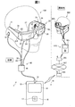
図1は、本発明の一実施形態における表示システムの概略構成を示す説明図である。表示システム1は、2台の頭部装着型表示装置100、400を備える。一方の頭部装着型表示装置100は、例えばスーパーマーケット等の店舗(ショッピング施設)内で、買い物支援者によって使用される。他方の頭部装着型表示装置400は、例えば店舗から離れた自宅内で、買い物受援者によって使用される。
A. Overall configuration of display system:
FIG. 1 is an explanatory diagram showing a schematic configuration of a display system according to an embodiment of the present invention. The display system 1 includes two head-mounted
2台の頭部装着型表示装置100、400のそれぞれは、通信キャリアBSを介して無線通信でインターネットINTに接続されている。通信キャリアBSは、送受信アンテナや、無線基地局、交換局を含む。インターネットINTによって、2台の頭部装着型表示装置100、400は通信が可能となっている。一方の頭部装着型表示装置100、すなわち、店舗内で買い物支援者によって使用されるHMD100の構成について、まず説明する。
Each of the two head-mounted
B.頭部装着型表示装置の構成:
頭部装着型表示装置100は、買い物支援者(以下、「使用者」とも呼ぶ)の頭部に装着する表示装置であり、ヘッドマウントディスプレイ(Head Mounted Display、HMD)とも呼ばれる。HMD100は、グラスを通過して視認される外界の中に画像が浮かび上がるシースルー型(透過型)の頭部装着型表示装置である。
B. Configuration of head-mounted display device:
The head-mounted
HMD100は、使用者に画像を視認させる画像表示部20と、画像表示部20を制御する制御装置(コントローラー)10とを備えている。
The
画像表示部20は、使用者の頭部に装着される装着体であり、本実施形態では眼鏡形状を有する。画像表示部20は、右保持部21と、左保持部23と、前部フレーム27とを有する本体に、右表示ユニット22と、左表示ユニット24と、右導光板26と、左導光板28とを備える。
The
右保持部21および左保持部23は、それぞれ、前部フレーム27の両端部から後方に延び、眼鏡のテンプル(つる)のように、使用者の頭部に画像表示部20を保持する。ここで、前部フレーム27の両端部のうち、画像表示部20の装着状態において使用者の右側に位置する端部を端部ERとし、使用者の左側に位置する端部を端部ELとする。右保持部21は、前部フレーム27の端部ERから、画像表示部20の装着状態における使用者の右側頭部に対応する位置まで延伸して設けられている。左保持部23は、前部フレーム27の端部ELから、画像表示部20の装着状態における使用者の左側頭部に対応する位置まで延伸して設けられている。
The
右導光板26および左導光板28は、前部フレーム27に設けられている。右導光板26は、画像表示部20の装着状態における使用者の右眼の眼前に位置し、右眼に画像を視認させる。左導光板28は、画像表示部20の装着状態における使用者の左眼の眼前に位置し、左眼に画像を視認させる。
The right
前部フレーム27は、右導光板26の一端と左導光板28の一端とを互いに連結した形状を有する。この連結位置は、画像表示部20の装着状態における使用者の眉間の位置に対応する。前部フレーム27には、右導光板26と左導光板28との連結位置において、画像表示部20の装着状態において使用者の鼻に当接する鼻当て部が設けられていてもよい。この場合、鼻当て部と右保持部21と左保持部23とによって、画像表示部20を使用者の頭部に保持できる。また、右保持部21および左保持部23に対して、画像表示部20の装着状態において使用者の後頭部に接するベルトを連結してもよい。この場合、ベルトによって画像表示部20を使用者の頭部に強固に保持できる。
The
右表示ユニット22は、右導光板26による画像の表示を行う。右表示ユニット22は、右保持部21に設けられ、画像表示部20の装着状態における使用者の右側頭部の近傍に位置する。左表示ユニット24は、左導光板28による画像の表示を行う。左表示ユニット24は、左保持部23に設けられ、画像表示部20の装着状態における使用者の左側頭部の近傍に位置する。なお、右表示ユニット22および左表示ユニット24を総称して「表示駆動部」とも呼ぶ。
The
本実施形態の右導光板26および左導光板28は、光透過性の樹脂等によって形成される光学部(例えばプリズム)であり、右表示ユニット22および左表示ユニット24が出力する画像光を使用者の眼に導く。なお、右導光板26および左導光板28の表面には、調光板が設けられてもよい。調光板は、光の波長域により透過率が異なる薄板状の光学素子であり、いわゆる波長フィルターとして機能する。調光板は、例えば、前部フレーム27の表面(使用者の眼と対向する面とは反対側の面)を覆うように配置される。調光板の光学特性を適宜選択することにより、可視光、赤外光、および紫外光等の任意の波長域の光の透過率を調整することができ、外部から右導光板26および左導光板28に入射し、右導光板26および左導光板28を透過する外光の光量を調整できる。
The right
画像表示部20は、右表示ユニット22および左表示ユニット24がそれぞれ生成する画像光を、右導光板26および左導光板28に導き、この画像光によって画像(拡張現実感(AR)画像)を使用者に視認させる(これを「画像を表示する」とも呼ぶ)。使用者の前方から右導光板26および左導光板28を透過して外光が使用者の眼に入射する場合、使用者の眼には、画像を構成する画像光と、外光とが入射する。このため、使用者における画像の視認性は、外光の強さに影響を受ける。
The
このため、例えば前部フレーム27に調光板を装着し、調光板の光学特性を適宜選択あるいは調整することによって、画像の視認のしやすさを調整することができる。典型的な例では、HMD100を装着した使用者が少なくとも外の景色を視認できる程度の光透過性を有する調光板を選択することができる。調光板を用いると、右導光板26および左導光板28を保護し、右導光板26および左導光板28の損傷や汚れの付着等を抑制する効果が期待できる。調光板は、前部フレーム27、あるいは、右導光板26および左導光板28のそれぞれに対して着脱可能としてもよい。また、複数種類の調光板を交換して着脱可能としてもよく、調光板を省略してもよい。
Therefore, for example, by attaching a dimmer to the
カメラ61は、画像表示部20の前部フレーム27に配置されている。カメラ61は、前部フレーム27の前面において、右導光板26および左導光板28を透過する外光を遮らない位置に設けられる。図1の例では、カメラ61は、右導光板26と左導光板28との連結部に配置されている。カメラ61は、前部フレーム27の端部ER側に配置されていてもよく、前部フレーム27の端部EL側に配置されていてもよい。
The
カメラ61は、CCDやCMOS等の撮像素子、および、撮像レンズ等を備えるデジタルカメラである。本実施形態のカメラ61は単眼カメラであるが、ステレオカメラを採用してもよい。カメラ61は、HMD100の表側方向、換言すれば、画像表示部20の装着状態において使用者が視認する視界方向の、少なくとも一部の外景(実空間)を撮像する。換言すれば、カメラ61は、使用者の視界と重なる範囲または方向を撮像し、使用者が視認する方向を撮像する。カメラ61の画角の広さは適宜設定できる。本実施形態では、カメラ61の画角の広さは、使用者が右導光板26および左導光板28を透過して視認可能な使用者の視界の全体を撮像するように設定される。カメラ61は、制御機能部150(図5)の制御に従って撮像を実行し、得られた撮像データを制御機能部150へ出力する。
The
測距センサー62は、前部フレーム27の右導光板26と左導光板28との連結部分におけるカメラ61の上部に配置されている。測距センサー62は、予め設定された測定方向に位置する測定対象物までの距離を検出する。測定方向は、MD100の表側方向(カメラ61の撮像方向と重複する方向)とすることができる。測距センサーは、例えば、LEDやレーザーダイオード等の発光部と、光源が発する光が測定対象物に反射する反射光を受光する受光部と、により構成できる。この場合、三角測距処理や、時間差に基づく測距処理により距離を求める。測距センサーは、例えば、超音波を発する発信部と、測定対象物で反射する超音波を受信する受信部と、により構成してもよい。この場合、時間差に基づく測距処理により距離を求める。測距センサーはカメラ61と同様に、制御機能部150により制御され、検出結果を制御機能部150へ出力する。
The
図2は、画像表示部20が備える光学系の構成を示す要部平面図である。説明の便宜上、図2には使用者の右眼REおよび左眼LEを図示する。図2に示すように、右表示ユニット22と左表示ユニット24とは、左右対称に構成されている。
FIG. 2 is a plan view of a main part showing the configuration of the optical system included in the
右眼REに画像(AR画像)を視認させる構成として、右表示ユニット22は、OLED(Organic Light Emitting Diode)ユニット221と、右光学系251とを備える。OLEDユニット221は、画像光を発する。右光学系251は、レンズ群等を備え、OLEDユニット221が発する画像光Lを右導光板26へと導く。
The
OLEDユニット221は、OLEDパネル223と、OLEDパネル223を駆動するOLED駆動回路225とを有する。OLEDパネル223は、有機エレクトロルミネッセンスにより発光し、R(赤)、G(緑)、B(青)の色光をそれぞれ発する発光素子により構成される自発光型の表示パネルである。OLEDパネル223は、R、G、Bの素子を1個ずつ含む単位を1画素とした複数の画素が、マトリクス状に配置されている。
The
OLED駆動回路225は、制御機能部150(図5)の制御に従って、OLEDパネル223が備える発光素子の選択および通電を実行し、発光素子を発光させる。OLED駆動回路225は、OLEDパネル223の裏面、すなわち発光面の裏側に、ボンディング等により固定されている。OLED駆動回路225は、例えばOLEDパネル223を駆動する半導体デバイスで構成され、OLEDパネル223の裏面に固定される基板に実装されてもよい。この基板には、後述する温度センサー217(図5)が実装される。なお、OLEDパネル223は、白色に発光する発光素子をマトリクス状に配置し、R、G、Bの各色に対応するカラーフィルターを重ねて配置する構成を採用してもよい。また、R、G、Bの色光をそれぞれ放射する発光素子に加えて、W(白)の光を放射する発光素子を備えるWRGB構成のOLEDパネル223が採用されてもよい。
The
右光学系251は、OLEDパネル223から射出された画像光Lを並行状態の光束にするコリメートレンズを有する。コリメートレンズにより並行状態の光束にされた画像光Lは、右導光板26に入射する。右導光板26の内部において光を導く光路には、画像光Lを反射する複数の反射面が形成される。画像光Lは、右導光板26の内部で複数回の反射を経て右眼RE側に導かれる。右導光板26には、右眼REの眼前に位置するハーフミラー261(反射面)が形成される。画像光Lは、ハーフミラー261で反射後、右導光板26から右眼REへと射出され、この画像光Lが右眼REの網膜で像を結ぶことで、使用者に画像を視認させる。
The right
左眼LEに画像(AR画像)を視認させる構成として、左表示ユニット24は、OLEDユニット241と、左光学系252とを備える。OLEDユニット241は画像光を発する。左光学系252は、レンズ群等を備え、OLEDユニット241が発する画像光Lを左導光板28へと導く。OLEDユニット241は、OLEDパネル243と、OLEDパネル243を駆動するOLED駆動回路245を有する。各部の詳細は、OLEDユニット221、OLEDパネル223、OLED駆動回路225と同じである。OLEDパネル243の裏面に固定される基板には、温度センサー239が実装される。また、左光学系252の詳細は右光学系251と同じである。
The
以上説明した構成によれば、HMD100は、シースルー型の表示装置として機能することができる。すなわち使用者の右眼REには、ハーフミラー261で反射した画像光Lと、右導光板26を透過した外光OLとが入射する。使用者の左眼LEには、ハーフミラー281で反射した画像光Lと、左導光板28を透過した外光OLとが入射する。このように、HMD100は、内部で処理した画像の画像光Lと外光OLとを重ねて使用者の眼に入射させる。この結果、使用者にとっては、右導光板26および左導光板28を透かして外景(実世界)が見えると共に、この外景に重なるようにして画像光Lによる画像(AR画像)が視認される。
According to the configuration described above, the
なお、ハーフミラー261およびハーフミラー281は、右表示ユニット22および左表示ユニット24がそれぞれ出力する画像光を反射して画像を取り出す「画像取り出し部」として機能する。また、右光学系251および右導光板26を総称して「右導光部」とも呼び、左光学系252および左導光板28を総称して「左導光部」とも呼ぶ。右導光部および左導光部の構成は、上述した例に限定されず、画像光を用いて使用者の眼前に画像を形成する限りにおいて任意の方式を用いることができる。例えば、右導光部および左導光部には、回折格子を用いてもよいし、半透過反射膜を用いてもよい。
The
図1において、制御装置10と画像表示部20とは、接続ケーブル40によって接続される。接続ケーブル40は、制御装置10の下部に設けられるコネクターに着脱可能に接続され、左保持部23の先端から、画像表示部20内部の各種回路に接続する。接続ケーブル40には、デジタルデータを伝送するメタルケーブルまたは光ファイバーケーブルを有する。接続ケーブル40にはさらに、アナログデータを伝送するメタルケーブルを含んでもよい。接続ケーブル40の途中には、コネクター46が設けられている。
In FIG. 1, the
コネクター46は、ステレオミニプラグを接続するジャックであり、コネクター46と制御装置10とは、例えばアナログ音声信号を伝送するラインで接続される。図1に示す本実施形態の例では、コネクター46には、ステレオヘッドホンを構成する右イヤホン32および左イヤホン34と、マイク63を有するヘッドセット30とが接続されている。
The
マイク63は、例えば図1に示すように、マイク63の集音部が使用者の視線方向を向くように配置されている。マイク63は、音声を集音し、音声信号を音声インターフェース182(図5)に出力する。マイク63は、モノラルマイクであってもステレオマイクであってもよく、指向性を有するマイクであっても無指向性のマイクであってもよい。
As shown in FIG. 1, for example, the
制御装置10は、HMD100を制御するための装置である。制御装置10は、点灯部12と、タッチパッド14と、方向キー16と、決定キー17と、電源スイッチ18とを含んでいる。点灯部12は、HMD100の動作状態(例えば、電源のON/OFF等)を、その発光態様によって通知する。点灯部12としては、例えば、LED(Light Emitting Diode)を用いることができる。
The
タッチパッド14は、タッチパッド14の操作面上での接触操作を検出して、検出内容に応じた信号を出力する。タッチパッド14としては、静電式や圧力検出式、光学式といった種々のタッチパッドを採用することができる。方向キー16は、上下左右方向に対応するキーへの押下操作を検出して、検出内容に応じた信号を出力する。決定キー17は、押下操作を検出して、制御装置10において操作された内容を決定するための信号を出力する。電源スイッチ18は、スイッチのスライド操作を検出することで、HMD100の電源の状態を切り替える。
The
図3は、使用者から見た画像表示部20の要部構成を示す図である。図3では、接続ケーブル40、右イヤホン32、左イヤホン34の図示を省略している。図3の状態では、右導光板26および左導光板28の裏側が視認できると共に、右眼REに画像光を照射するためのハーフミラー261、および、左眼LEに画像光を照射するためのハーフミラー281が略四角形の領域として視認できる。使用者は、これらハーフミラー261、281を含む左右の導光板26、28の全体を透過して外景を視認すると共に、ハーフミラー261、281の位置に矩形の表示画像を視認する。
FIG. 3 is a diagram showing a configuration of a main part of the
図4は、カメラ61の画角を説明するための図である。図4では、カメラ61と、使用者の右眼REおよび左眼LEとを平面視で模式的に示すと共に、カメラ61の画角(撮像範囲)をθで示す。なお、カメラ61の画角θは図示のように水平方向に拡がっているほか、一般的なデジタルカメラと同様に鉛直方向にも拡がっている。
FIG. 4 is a diagram for explaining the angle of view of the
上述のようにカメラ61は、画像表示部20の前部フレーム27において導光板26と左導光板28との連結部に配置され、使用者の視線の方向(すなわち使用者の前方)を撮像する。このためカメラ61の光軸は、右眼REおよび左眼LEの視線方向を含む方向とされる。使用者がHMD100を装着した状態で視認できる外景は、無限遠とは限らない。例えば、使用者が両眼で対象物OBを注視すると、使用者の視線は、図中の符号RD、LDに示すように、対象物OBに向けられる。この場合、使用者から対象物OBまでの距離は、30cm〜10m程度であることが多く、1m〜4mであることがより多い。そこで、HMD100について、通常使用時における使用者から対象物OBまでの距離の上限および下限の目安を定めてもよい。この目安は、予め求められHMD100にプリセットされていてもよいし、使用者が設定してもよい。カメラ61の光軸および画角は、このような通常使用時における対象物OBまでの距離が、設定された上限および下限の目安に相当する場合において対象物OBが画角に含まれるように設定されることが好ましい。
As described above, the
なお、一般的に、人間の視野角は水平方向におよそ200度、垂直方向におよそ125度とされる。そのうち情報受容能力に優れる有効視野は水平方向に30度、垂直方向に20度程度である。人間が注視する注視点が迅速に安定して見える安定注視野は、水平方向に60〜90度、垂直方向に45〜70度程度とされている。この場合、注視点が対象物OB(図4)であるとき、視線RD、LDを中心として水平方向に30度、垂直方向に20度程度が有効視野である。また、水平方向に60〜90度、垂直方向に45〜70度程度が安定注視野である。使用者が画像表示部20を透過して右導光板26および左導光板28を透過して視認する実際の視野を、実視野(FOV:Field Of View)と呼ぶ。実視野は、視野角および安定注視野より狭いが、有効視野より広い。
Generally, the viewing angle of a human is about 200 degrees in the horizontal direction and about 125 degrees in the vertical direction. Among them, the effective visual field having excellent information receiving ability is about 30 degrees in the horizontal direction and about 20 degrees in the vertical direction. The stable gazing field at which a human gaze can be seen quickly and stably is 60 to 90 degrees in the horizontal direction and 45 to 70 degrees in the vertical direction. In this case, when the gazing point is the object OB (FIG. 4), the effective field of view is about 30 degrees in the horizontal direction and about 20 degrees in the vertical direction with the lines of sight RD and LD as the center. The stable gaze is 60 to 90 degrees in the horizontal direction and 45 to 70 degrees in the vertical direction. The actual field of view that the user sees through the
本実施形態のカメラ61の画角θは、使用者の視野より広い範囲を撮像可能に設定される。カメラ61の画角θは、少なくとも使用者の有効視野より広い範囲を撮像可能に設定されることが好ましく、実視野よりも広い範囲を撮像可能に設定されることがより好ましい。カメラ61の画角θは、使用者の安定注視野より広い範囲を撮像可能に設定されることがさらに好ましく、使用者の両眼の視野角よりも広い範囲を撮像可能に設定されることが最も好ましい。このため、カメラ61には、撮像レンズとしていわゆる広角レンズを備え、広い画角を撮像できる構成としてもよい。広角レンズには、超広角レンズ、準広角レンズと呼ばれるレンズを含んでもよい。また、カメラ61には、単焦点レンズを含んでもよく、ズームレンズを含んでもよく、複数のレンズからなるレンズ群を含んでもよい。
The angle of view θ of the
図5は、HMD100の構成を機能的に示すブロック図である。制御装置10は、プログラムを実行してHMD100を制御するメインプロセッサー140と、記憶部と、入出力部と、センサー類と、インターフェースと、電源部130とを備える。メインプロセッサー140には、これらの記憶部、入出力部、センサー類、インターフェース、電源部130がそれぞれ接続されている。メインプロセッサー140は、制御装置10が内蔵しているコントローラー基板120に実装されている。
FIG. 5 is a block diagram functionally showing the configuration of the
記憶部には、メモリー118と、不揮発性記憶部121とが含まれている。メモリー118は、メインプロセッサー140によって実行されるコンピュータープログラム、および、処理されるデータを一時的に記憶するワークエリアを構成する。不揮発性記憶部121は、フラッシュメモリーやeMMC(embedded Multi Media Card)で構成される。不揮発性記憶部121は、メインプロセッサー140が実行するコンピュータープログラムや、メインプロセッサー140によって処理される各種のデータを記憶する。本実施形態において、これらの記憶部はコントローラー基板120に実装されている。
The storage unit includes a
入出力部には、タッチパッド14と、操作部110とが含まれている。操作部110には、制御装置10に備えられた方向キー16と、決定キー17と、電源スイッチ18とが含まれる。メインプロセッサー140は、これら各入出力部を制御すると共に、各入出力部から出力される信号を取得する。
The input / output unit includes a
センサー類には、6軸センサー111と、磁気センサー113と、GPS(Global Positioning System)レシーバー115とが含まれている。6軸センサー111は、3軸加速度センサーと3軸ジャイロ(角速度)センサーとを備えるモーションセンサー(慣性センサー)である。6軸センサー111は、これらセンサーがモジュール化されたIMU(Inertial Measurement Unit)を採用してもよい。磁気センサー113は、例えば、3軸の地磁気センサーである。GPSレシーバー115は、図示しないGPSアンテナを備え、GPS衛星から送信される無線信号を受信して、制御装置10の現在位置の座標を検出する。これらセンサー類(6軸センサー111、磁気センサー113、GPSレシーバー115)は、検出値を予め指定されたサンプリング周波数に従って、メインプロセッサー140へと出力する。各センサーが検出値を出力するタイミングは、メインプロセッサー140からの指示に応じてもよい。
The sensors include a 6-
インターフェースには、無線通信部117と、音声コーデック180と、外部コネクター184と、外部メモリーインターフェース186と、USB(Universal Serial Bus)コネクター188と、センサーハブ192と、FPGA194と、インターフェース196とが含まれている。これらは、外部とのインターフェースとして機能する。無線通信部117は、HMD100と外部機器との間における無線通信を実行する。無線通信部117は、図示しないアンテナ、RF回路、ベースバンド回路、通信制御回路等を備えて構成され、あるいはこれらが統合されたデバイスとして構成されている。無線通信部117は、例えば、Wi−Fi(登録商標)を含む無線LANや、Bluetooth(登録商標)、iBeacon(登録商標)等の規格に準拠した無線通信を行う。
The interface includes a wireless communication unit 117, a
音声コーデック180は、音声インターフェース182に接続され、音声インターフェース182を介して入出力される音声信号のエンコード/デコードを行う。音声インターフェース182は、音声信号を入出力するインターフェースである。音声コーデック180は、アナログ音声信号からデジタル音声データへの変換を行うA/Dコンバーター、および、その逆の変換を行うD/Aコンバーターを備えてもよい。本実施形態のHMD100は、音声を右イヤホン32および左イヤホン34から出力し、マイク63により集音する。音声コーデック180は、メインプロセッサー140が出力するデジタル音声データをアナログ音声信号に変換し、音声インターフェース182を介して出力する。また、音声コーデック180は、音声インターフェース182に入力されるアナログ音声信号をデジタル音声データに変換してメインプロセッサー140に出力する。
The
外部コネクター184は、メインプロセッサー140に対して、メインプロセッサー140と通信する外部装置(例えば、パーソナルコンピューター、スマートフォン、ゲーム機器等)を接続するためのコネクターである。外部コネクター184に接続された外部装置は、コンテンツの供給元となり得るほか、メインプロセッサー140が実行するコンピュータープログラムのデバッグや、HMD100の動作ログの収集に使用できる。外部コネクター184は種々の態様を採用できる。外部コネクター184としては、例えば、USBインターフェース、マイクロUSBインターフェース、メモリーカード用インターフェース等の有線接続に対応したインターフェースや、無線LANインターフェース、Bluetoothインターフェース等の無線接続に対応したインターフェースを採用できる。
The
外部メモリーインターフェース186は、可搬型のメモリーデバイスを接続可能なインターフェースである。外部メモリーインターフェース186は、例えば、カード型記録媒体を装着してデータの読み書きを行うメモリーカードスロットと、インターフェース回路とを含む。カード型記録媒体のサイズ、形状、規格等は適宜選択できる。USBコネクター188は、USB規格に準拠したメモリーデバイス、スマートフォン、携帯電話端末、パーソナルコンピューター等を接続可能なインターフェースである。USBコネクター188は、例えば、USB規格に準拠したコネクターと、インターフェース回路とを含む。USBコネクター188のサイズ、形状、USB規格のバージョン等は適宜選択できる。
The
また、HMD100は、バイブレーター19を備える。バイブレーター19は、図示しないモーターと、偏芯した回転子等を備え、メインプロセッサー140の制御に従って振動を発声する。HMD100は、例えば、操作部110に対する操作を検出した場合や、HMD100の電源がオンオフされた場合等に所定の振動パターンでバイブレーター19により振動を発生させる。
The
センサーハブ192およびFPGA194は、インターフェース(I/F)196を介して画像表示部20に接続されている。センサーハブ192は、画像表示部20が備える各種センサーの検出値を取得して、メインプロセッサー140に出力する。FPGA194は、メインプロセッサー140と画像表示部20の各部との間で送受信されるデータの処理およびインターフェース196を介した伝送を実行する。インターフェース196は、画像表示部20の右表示ユニット22と、左表示ユニット24とに対してそれぞれ接続されている。本実施形態の例では、左保持部23に接続ケーブル40が接続され、この接続ケーブル40に繋がる配線が画像表示部20内部に敷設され、右表示ユニット22と左表示ユニット24とのそれぞれが、制御装置10のインターフェース196に接続される。
The sensor hub 192 and the
電源部130には、バッテリー132と、電源制御回路134とが含まれている。電源部130は、制御装置10が動作するための電力を供給する。バッテリー132は、充電可能な電池である。電源制御回路134は、バッテリー132の残容量の検出と、OS143への充電の制御を行う。電源制御回路134は、メインプロセッサー140に接続され、バッテリー132の残容量の検出値や、バッテリー132の電圧の検出値をメインプロセッサー140へと出力する。なお、電源部130が供給する電力に基づいて、制御装置10から画像表示部20へと電力を供給してもよい。電源部130から制御装置10の各部および画像表示部20への電力の供給状態を、メインプロセッサー140により制御可能な構成としてもよい。
The
右表示ユニット22は、表示ユニット基板210と、OLEDユニット221と、カメラ61と、照度センサー65と、LEDインジケーター67と、温度センサー217とを備える。表示ユニット基板210には、インターフェース196に接続されるインターフェース(I/F)211と、受信部(Rx)213と、EEPROM(Electrically Erasable Programmable Read-Only Memory)215とが実装されている。受信部213は、インターフェース211を介して制御装置10から入力されるデータを受信する。受信部213は、OLEDユニット221で表示する画像の画像データを受信した場合に、受信した画像データをOLED駆動回路225(図2)へと出力する。
The
EEPROM215は、各種のデータをメインプロセッサー140が読み取り可能な態様で記憶する。EEPROM215は、例えば、画像表示部20のOLEDユニット221、241の発光特性や表示特性に関するデータ、右表示ユニット22または左表示ユニット24のセンサー特性に関するデータ等を記憶する。具体的には、例えば、OLEDユニット221、241のガンマ補正に係るパラメーター、後述する温度センサー217、239の検出値を補償するデータ等を記憶する。これらのデータは、HMD100の工場出荷時の検査によって生成され、EEPROM215に書き込まれる。出荷後は、メインプロセッサー140がEEPROM215のデータを読み込んで各種の処理に利用する。
The
カメラ61は、インターフェース211を介して入力される信号に従って撮像を実行し、撮像画像データあるいは撮像結果を表す信号を制御装置10へと出力する。照度センサー65は、図1に示すように、前部フレーム27の端部ERに設けられ、画像表示部20を装着する使用者の前方からの外光を受光するように配置される。照度センサー65は、受光量(受光強度)に対応した検出値を出力する。LEDインジケーター67は、図1に示すように、前部フレーム27の端部ERにおいてカメラ61の近傍に配置される。LEDインジケーター67は、カメラ61による撮像を実行中に点灯して、撮像中であることを報知する。
The
温度センサー217は、温度を検出し、検出した温度に対応する電圧値あるいは抵抗値を出力する。温度センサー217は、OLEDパネル223(図3)の裏面側に実装される。温度センサー217は、例えばOLED駆動回路225と同一の基板に実装されてもよい。この構成により、温度センサー217は主としてOLEDパネル223の温度を検出する。なお、温度センサー217は、OLEDパネル223あるいはOLED駆動回路225に内蔵されてもよい。例えば、OLEDパネル223がSi−OLEDとしてOLED駆動回路225と共に統合半導体チップ上の集積回路として実装される場合、この半導体チップに温度センサー217を実装してもよい。
The
左表示ユニット24は、表示ユニット基板230と、OLEDユニット241と、温度センサー239とを備える。表示ユニット基板230には、インターフェース196に接続されるインターフェース(I/F)231と、受信部(Rx)233と、6軸センサー235と、磁気センサー237とが実装されている。受信部233は、インターフェース231を介して制御装置10から入力されるデータを受信する。受信部233は、OLEDユニット241で表示する画像の画像データを受信した場合に、受信した画像データをOLED駆動回路245(図2)へと出力する。
The
6軸センサー235は、3軸加速度センサーおよび3軸ジャイロ(角速度)センサーを備えるモーションセンサー(慣性センサー)である。6軸センサー235は、上記のセンサーがモジュール化されたIMUを採用してもよい。6軸センサー235は、画像表示部20に設けられているため、画像表示部20が使用者の頭部に装着されているときには、使用者の頭部の動きを検出する。検出された使用者USの頭部の動きから画像表示部20の向きがわかる。磁気センサー237は、例えば、3軸の地磁気センサーである。温度センサー239は、温度を検出し、検出した温度に対応する電圧値あるいは抵抗値を出力する。温度センサー239は、OLEDパネル243(図3)の裏面側に実装される。温度センサー239は、例えばOLED駆動回路245と同一の基板に実装されてもよい。この構成により、温度センサー239は主としてOLEDパネル243の温度を検出する。温度センサー239は、OLEDパネル243あるいはOLED駆動回路245に内蔵されてもよい。詳細は温度センサー217と同様である。
The 6-
右表示ユニット22のカメラ61、照度センサー65、温度センサー217と、左表示ユニット24の6軸センサー235、磁気センサー237、温度センサー239は、制御装置10のセンサーハブ192に接続される。センサーハブ192は、メインプロセッサー140の制御に従って各センサーのサンプリング周期の設定および初期化を行う。センサーハブ192は、各センサーのサンプリング周期に合わせて、各センサーへの通電、制御データの送信、検出値の取得等を実行する。センサーハブ192は、予め設定されたタイミングで、右表示ユニット22および左表示ユニット24が備える各センサーの検出値をメインプロセッサー140へ出力する。センサーハブ192は、各センサーの検出値を一時的に保持するキャッシュ機能を備えてもよい。センサーハブ192は、各センサーの検出値の信号形式やデータ形式の変換機能(例えば、統一形式への変換機能)を備えてもよい。センサーハブ192は、メインプロセッサー140の制御に従ってLEDインジケーター67への通電を開始および停止させることで、LEDインジケーター67を点灯または消灯させる。
The
図6は、制御装置10の構成を機能的に示すブロック図である。制御装置10は、機能的には、記憶機能部122と、制御機能部150とを備える。記憶機能部122は、不揮発性記憶部121(図5)により構成される論理的な記憶部である。記憶機能部122は、記憶機能部122のみを使用する構成に替えて、不揮発性記憶部121に組み合わせてEEPROM215やメモリー118を使用する構成としてもよい。制御機能部150は、メインプロセッサー140がコンピュータープログラムを実行することにより、すなわち、ハードウェアとソフトウェアとが協働することにより構成される。
FIG. 6 is a block diagram functionally showing the configuration of the
記憶機能部122には、制御機能部150における処理に供する種々のデータが記憶されている。具体的には、本実施形態の記憶機能部122には、設定データ123と、コンテンツデータ124とが記憶されている。設定データ123は、HMD100の動作に係る各種の設定値を含む。例えば、設定データ123には、制御機能部150がHMD100を制御する際のパラメーター、行列式、演算式、LUT(Look Up Table)等が含まれている。
The
コンテンツデータ124には、制御機能部150の制御によって画像表示部20が表示する画像や映像を含むコンテンツのデータ(画像データ、映像データ、音声データ等)が含まれている。なお、コンテンツデータ124には、双方向型のコンテンツのデータが含まれてもよい。双方向型のコンテンツとは、操作部110によって使用者の操作を取得して、取得した操作内容に応じた処理を制御機能部150が実行し、処理内容に応じたコンテンツを画像表示部20に表示するタイプのコンテンツを意味する。この場合、コンテンツのデータには、使用者の操作を取得するためのメニュー画面の画像データ、メニュー画面に含まれる項目に対応する処理を定めるデータ等を含みうる。
The
制御機能部150は、記憶機能部122が記憶しているデータを利用して各種処理を実行することにより、OS143、画像処理部145、表示制御部147、撮像制御部149、入出力制御部151、通信制御部153、買い物支援処理部155としての機能を実行する。本実施形態では、OS143以外の各機能部は、OS143上で実行されるコンピュータープログラムとして構成されている。
The
画像処理部145は、画像表示部20により表示する画像/映像の画像データに基づいて、右表示ユニット22および左表示ユニット24に送信する信号を生成する。画像処理部145が生成する信号は、垂直同期信号、水平同期信号、クロック信号、アナログ画像信号等であってもよい。画像処理部145は、メインプロセッサー140がコンピュータープログラムを実行して実現される構成のほか、メインプロセッサー140とは別のハードウェア(例えば、DSP(Digital Signal Processor))で構成してもよい。
The
なお、画像処理部145は、必要に応じて、解像度変換処理、画像調整処理、2D/3D変換処理等を実行してもよい。解像度変換処理は、画像データの解像度を右表示ユニット22および左表示ユニット24に適した解像度へと変換する処理である。画像調整処理は、画像データの輝度や彩度を調整する処理である。2D/3D変換処理は、三次元画像データから二次元画像データを生成し、あるいは、二次元画像データから三次元画像データを生成する処理である。画像処理部145は、これらの処理を実行した場合、処理後の画像データに基づき画像を表示するための信号を生成し、接続ケーブル40を介して画像表示部20へと送信する。
The
表示制御部147は、右表示ユニット22および左表示ユニット24を制御する制御信号を生成し、この制御信号により、右表示ユニット22および左表示ユニット24のそれぞれによる画像光の生成と射出とを制御する。具体的には、表示制御部147は、OLED駆動回路225、245を制御して、OLEDパネル223、243による画像の表示を実行させる。表示制御部147は、画像処理部145が出力する信号に基づいて、OLED駆動回路225、245がOLEDパネル223、243に描画するタイミングの制御、OLEDパネル223、243の輝度の制御等を行う。
The
撮像制御部149は、カメラ61を制御して撮像を実行させ、撮像画像データを生成し、記憶機能部122に一時的に記憶させる。また、カメラ61が撮像画像データを生成する回路を含むカメラユニットとして構成される場合、撮像制御部149は、撮像画像データをカメラ61から取得して、記憶機能部122に一時的に記憶させる。
The image
入出力制御部151は、タッチパッド14(図1)と、方向キー16と、決定キー17とを適宜、制御して、これらから入力指令を取得する。取得した指令は、OS143、またはOS143と共にOS143上で動作するコンピュータープログラムに出力される。通信制御部153は、無線通信部117を制御して、例えば外部のHMD400との間で無線通信を行う。
The input /
買い物支援処理部155は、OS143上で動作するアプリケーションプログラムに従って実現される機能である。買い物支援処理部155は、検出された使用者の視線方向を含む所定の範囲を特定し、特定された所定の範囲に存在するBLE(Bluetooth Low Energy)端末と無線通信部117(図5)を介して通信を行い、BLE端末からデータを受信し、受信したデータに基づく提示情報を、買い物受援者が装着するHMD400に無線通信部117を介して送信する。買い物支援処理部155の詳細は、後述する。なお、買い物支援処理部155が[発明の概要]の欄に記載した本発明の第1の形態における「処理部」に相当する。
The shopping
図7は、HMD100による拡張現実感表示の一例を示す説明図である。図7では、使用者の視界VRを例示している。上述のようにして、HMD100の使用者の両眼に導かれた画像光が使用者の網膜に結像することにより、使用者は拡張現実感(AR)としての画像AIを視認する。図7の例では、画像AIは、HMD100のOSのメニュー画面である。メニュー画面には、例えば、「メッセージ」、「電話」、「カメラ」、「ブラウザー」、「買い物支援」の各アプリケーションプログラムを起動するためのアイコンICが含まれる。また、右左の導光板26,28が外景SCからの光を透過することで、使用者は外景SCを視認する。このように、HMD100の使用者は、視界VRのうち画像VIが表示された部分については、外景SCに重なるようにして画像AIを見ることができる。また、視界VRのうち画像AIが表示されていない部分については、外景SCだけを見ることができる。なお、図示の外景SCは街中であるが、HMD100は先に説明したように店舗内で使用されることから、外景SCは店舗内の眺めとなる。
FIG. 7 is an explanatory diagram showing an example of augmented reality display by the
先に説明したように、上述したHMD100は店舗内で買い物支援者によって使用され、他方のHMD400は店舗から離れた自宅内で買い物受援者によって使用される。以下、買い物支援者によって使用されるHMD100を「支援者HMD100」と呼び、買い物受援者によって使用されるHMD400を「受援者HMD400」と呼ぶ。受援者HMD400は、支援者HMD100と同一機種であり、インストールされている一部のアプリケーションプログラムだけが相違する。一部のアプリケーションプログラムが相違することで、受援者HMD400は、制御装置10の制御機能部が相違したものとなる。なお、受援者HMD400における支援者HMD100と同一の構成要素については、支援者HMD100と同一の符号を用いて以下の説明を行う。
As described above, the above-mentioned HMD100 is used by the shopping supporter in the store, while the HMD400 is used by the shopping supporter in the home away from the store. Hereinafter, the HMD100 used by the shopping supporter will be referred to as a “supporter HMD100”, and the HMD400 used by the shopping supporter will be referred to as a “supporter HMD400”. The supporter HMD400 is the same model as the supporter HMD100, and differs only in some installed application programs. Due to the difference in some application programs, the supporter HMD400 has a different control function unit of the
図8は、受援者HMD400の制御装置10の構成を機能的に示すブロック図である。制御装置10は、機能的には、記憶機能部122と、制御機能部450とを備える。記憶機能部122は、支援者HMD100の記憶機能部122と同一である。制御機能部450は、支援者HMD100の制御機能部150と比較して、買い物支援処理部155に換えて買い物処理部455が設けられている点が相違し、残余の構成要素(図中の143〜153)については同一である。
FIG. 8 is a block diagram functionally showing the configuration of the
買い物処理部455は、OS143上で動作するアプリケーションプログラムに従って実現される機能である。買い物処理部455は、買い物支援を要請するとともに、支援者HMD100とから送られてくる提示情報を表示する。買い物処理部455の詳細は、後述する。
The
図9は、受援者HMD400による拡張現実感表示の一例を示す説明図である。図9では、買い物受援者(以下、「使用者」とも呼ぶ)の視界VR2を例示している。上述のようにして、受援者HMD400の使用者の両眼に導かれた画像光が使用者の網膜に結像することにより、使用者は拡張現実感(AR)としての画像AI2を視認する。図7の例では、画像AI2は、受援者HMD400のOSのメニュー画面である。メニュー画面には、例えば、「メッセージ」、「電話」、「カメラ」、「ブラウザー」、「遠隔買い物」の各アプリケーションプログラムを起動するためのアイコンIC2が含まれる。また、右左の導光板26,28が外景SC2からの光を透過することで、使用者は外景SC2を視認する。このように、受援者HMD400の使用者は、視界VR2のうち画像VI2が表示された部分については、外景SC2に重なるようにして画像AI2を見ることができる。また、視界VR2のうち画像AI2が表示されていない部分については、外景SC2だけを見ることができる。なお、図示の外景SC2は街中であるが、受援者HMD400は先に説明したように自宅内で使用されることから、外景SC2は自宅内の眺めとなる。
FIG. 9 is an explanatory diagram showing an example of augmented reality display by the supporter HMD400. FIG. 9 illustrates the field of view VR2 of the shopping supporter (hereinafter, also referred to as “user”). As described above, the image light guided to both eyes of the user of the supporter HMD400 is imaged on the retina of the user, so that the user visually recognizes the image AI2 as augmented reality (AR). .. In the example of FIG. 7, the image AI2 is the OS menu screen of the supporter HMD400. The menu screen includes, for example, an icon IC2 for activating each application program of "message", "telephone", "camera", "browser", and "remote shopping". Further, the right and left
C.買い物に関わる工程について:
図10は、買い物を行うに際し受援者HMD400側および支援者HMD100側で実行する工程を示す説明図である。買い物を行うに際し、まず、受援者HMD400を装着した買い物受援者(以下、単に「受援者」とも呼ぶ)は、買い物の支援をして欲しい旨を店舗に要請する(工程P1)。具体的には、受援者は、メニュー画面に用意された「遠隔買い物」のアイコンIC2を方向キー16(図1)と決定キー17(図1)によって指示することによって、USBコネクター188(図5)を介して携帯電話端末と通信を行って、予め登録された店舗に電話をする。この電話で、買い物の支援をして欲しい旨を店舗に要請する。支援の要請は、電話に替えて、メール等の別の通信手段によるものとすることもできる。
C. About the process related to shopping:
FIG. 10 is an explanatory diagram showing a process executed on the supporter HMD400 side and the supporter HMD100 side when shopping. When shopping, first, the shopping supporter wearing the supporter HMD400 (hereinafter, also simply referred to as “supporter”) requests the store to support the shopping (process P1). Specifically, the supporter instructs the icon IC2 of "remote shopping" prepared on the menu screen by the direction key 16 (FIG. 1) and the enter key 17 (FIG. 1), thereby causing the USB connector 188 (FIG. 1). Communicate with the mobile phone terminal via 5) and call the pre-registered store. Use this phone to ask the store to help you with your shopping. Requests for assistance can be made by other means of communication, such as email, instead of telephone.
買い物支援の要請を受けた店舗では、店舗内に予め待機している、支援者HMD100を装着した買い物支援者(以下、単に「支援者」とも呼ぶ)に、買い物支援を行うよう指示する。指示を受けた支援者は、支援者HMD100と受援者HMD400との間の通信を確立した上で、買い物受援者が装着している受援者HMD400に対して買い物支援を受託した旨を送信する(工程P2)。支援者HMD100と受援者HMD400との間の通信は、データ転送は勿論のこと、音声通話も含む。 At the store that receives the request for shopping support, the shopping supporter wearing the supporter HMD100 (hereinafter, also simply referred to as “supporter”), who is waiting in advance in the store, is instructed to provide shopping support. The supporter who received the instruction establishes communication between the supporter HMD100 and the supporter HMD400, and then entrusts the shopping support to the supporter HMD400 worn by the shopping supporter. Transmit (step P2). Communication between the supporter HMD100 and the supporter HMD400 includes not only data transfer but also voice communication.
さらに、支援者HMD100は、カメラ61によって撮像した撮像画像を受援者HMD400に対して送信する(工程P3)。
Further, the supporter HMD100 transmits the captured image captured by the
受援者HMD400は、支援者HMD100から送られてくる撮像画像を受信し、受信した撮像画像を表示する(工程P4)。具体的には、撮像画像に基づいて画像処理部145(図6)を制御して、表示制御部147(図6)に撮像画像の表示を実行させる。その結果、支援者HMD100で撮像した撮像画像が受援者HMD400に表示される。これにより、受援者HMD400を装着した受援者は、自宅に居ながら店舗内の画像を見ることができる。なお、これ以後、買い物支援が終了するまで、撮像画像は支援者HMD100から受援者HMD400に送り続けられ、受援者HMD400では店舗内の状況を逐次に見ることができる。 The supporter HMD400 receives the captured image sent from the supporter HMD100 and displays the received captured image (step P4). Specifically, the image processing unit 145 (FIG. 6) is controlled based on the captured image, and the display control unit 147 (FIG. 6) is made to display the captured image. As a result, the captured image captured by the supporter HMD100 is displayed on the supporter HMD400. As a result, the supporter wearing the supporter HMD400 can see the image in the store while staying at home. After that, the captured image is continuously sent from the supporter HMD100 to the supporter HMD400 until the shopping support is completed, and the supporter HMD400 can sequentially see the situation in the store.
支援者は、商品を眺めながら店舗内を順に見ていく。そのとき、受援者は、受援者HMD400を用いて、支援者HMD100に対して指示を送信する(工程P5)。具体的には、受援者は、支援者HMD100に、音声通話によって望む売り場に移動する旨を送信する。例えば、「果物が欲しいわ」といった指示を送る。 The supporter looks at the store in order while looking at the products. At that time, the supporter uses the supporter HMD400 to transmit an instruction to the supporter HMD100 (step P5). Specifically, the supporter transmits to the supporter HMD100 that he / she will move to the desired sales floor by voice call. For example, send an instruction such as "I want fruit".
指示を受けた支援者は、指示に基づいて移動する(工程P6)。例えば、果物売り場に移動する。続いて、支援者HMD100は、支援者の視線方向周りの商品の種類毎の提示情報を取得し(工程P7)、取得した提示情報を受援者HMD400に送信する(工程P8)。どのように提示情報を取得するかは、後述する。 The supporter who received the instruction moves based on the instruction (step P6). For example, move to the fruit counter. Subsequently, the supporter HMD100 acquires presentation information for each type of product around the line-of-sight direction of the supporter (process P7), and transmits the acquired presentation information to the supporter HMD400 (process P8). How to obtain the presentation information will be described later.
受援者HMD400は、支援者HMD100から送られてくる提示情報を受信し、提示情報を表示する(工程P9)。具体的には、提示情報に基づいて受援者HMD400の画像処理部145(図6)を制御して、受援者HMD400の表示制御部147(図6)に提示情報の表示を実行させる。この表示は、工程P4で表示している撮像画像に重ね合わせて表示する。受援者HMD400によって実行される工程P1,P4,P9が、買い物処理部455(図8)に対応している。 The supporter HMD400 receives the presentation information sent from the supporter HMD100 and displays the presentation information (step P9). Specifically, the image processing unit 145 (FIG. 6) of the supporter HMD400 is controlled based on the presentation information, and the display control unit 147 (FIG. 6) of the supporter HMD400 is made to display the presentation information. This display is superimposed on the captured image displayed in step P4 . The steps P1, P4, and P9 executed by the supporter HMD400 correspond to the shopping processing unit 455 (FIG. 8).
受援者HMD400を装着した受援者は、表示された提示情報を見て、好みの商品を発注する。商品の発注は、例えば音声通話にて、支援者HMD100に送る。 The supporter wearing the supporter HMD400 sees the displayed information and orders the desired product. The order for the product is sent to the supporter HMD100 by voice call, for example.
D.買い物支援処理について:
図11は、買い物支援処理を示すフローチャートである。この買い物支援処理は、買い物支援処理部155(図6)に対応しており、図10で言えば、工程P2,P3,P7,P8を実現している。買い物支援処理は、不揮発性記憶部121(図5)に格納されている所定のコンピュータープログラム(アプリケーションプログラム)に従う処理ルーチンで、支援者HMD100のメインプロセッサー140によって実行される。図7に例示したメニュー画面の「買い物支援」のアイコンICが方向キー16(図1)と決定キー17(図1)によって指示されたことを受けて、買い物支援処理は実行開始される。
D. About shopping support processing:
FIG. 11 is a flowchart showing the shopping support process. This shopping support processing corresponds to the shopping support processing unit 155 (FIG. 6), and in terms of FIG. 10, the processes P2, P3, P7, and P8 are realized. The shopping support process is a process routine that follows a predetermined computer program (application program) stored in the non-volatile storage unit 121 (FIG. 5), and is executed by the
処理が開始されると、支援者HMD100のメインプロセッサー140は、まず、支援者HMD100と受援者HMD400との間の通信を確立した上で、買い物受援者が装着している受援者HMD400に対して、買い物支援を受託した旨のメッセージを送信する(ステップS110)。この処理は、図10の工程P2に相当する。
When the process is started, the
次いで、メインプロセッサー140は、カメラ61を起動し(ステップS120)、カメラ61で撮像した画像を受援者HMD400に対して送信する(ステップS130)。カメラ61で撮像した画像は、先に説明したように、支援者の視野より広い範囲を撮像していることから、ここでは、支援者の視野に一致すべく撮像画像の周辺を削除した上で、受援者HMD400に送信する。すなわち、支援者の視野と一致する画像が受援者HMD400に送信される。ステップS130の処理は、図10の工程P3に相当する。なお、これ以後、撮像画像は、買い物支援が終了するまで送り続けられる。
Next, the
続いて、メインプロセッサー140は、受援者HMD400から指示が送られてきた場合に、その指示を受信する(ステップS140)。例えば、「果物が欲しいわ」といった指示を受ける。この処理は、図10の工程P5に対応する支援者HMD100側の処理である。
Subsequently, the
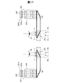
図12は、店舗内の果物売り場の一例を示す説明図である。図10に示した工程P6によって、支援者は、例えば果物売り場に移動する。果物売り場には、陳列棚DCが設けられている。陳列棚DCには、果物F1,F2,F3,F4が種類毎に区分けして陳列されている。例えば、第1の果物F1はミカンであり、第2の果物F2はバナナであり、第3の果物F3はリンゴであり、第4の果物F4はレモンである。例えば、陳列棚DCの左から右に向かって、ミカンの群C1と、バナナの群C2と、リンゴの群C3と、レモンの群C4と、が配列される。各群C1,C2,C3,C4の上端には、BLE端末501,502,503,504がそれぞれ設けられている。BLE(Bluetooth Low Energy)とは、近距離無線通信技術Bluetooth(登録商標)の拡張仕様の一つで、極低電力で通信が可能なものである。支援者HMD100の無線通信部117(図5)は、BLE端末と通信を行うことが可能となっている。支援者HMD100を装着した支援者は、受援者からの移動指示に従って、陳列棚DCの前に移動する。
FIG. 12 is an explanatory diagram showing an example of a fruit counter in a store. According to step P6 shown in FIG. 10, the supporter moves to, for example, a fruit counter. A display shelf DC is provided in the fruit counter. Fruits F1, F2, F3, and F4 are classified and displayed on the display shelf DC according to their types. For example, the first fruit F1 is a mandarin orange, the second fruit F2 is a banana, the third fruit F3 is an apple, and the fourth fruit F4 is a lemon. For example, from left to right of the display shelf DC, a group C1 of oranges, a group C2 of bananas, a group C3 of apples, and a group C4 of lemons are arranged.
図11に戻り、その後、メインプロセッサー140は、画像表示部20を装着した使用者(支援者)の視線方向を求める(ステップS150)。ここで言う「視線方向」は、使用者が両眼で見る方向である。ステップS150では、画像表示部20の向きが使用者の視線方向と一致するとして、画像表示部20に備え付けられた6軸センサー235の検出信号から画像表示部20の向きを特定することによって、視線方向を求める。「視線方向」は、左眼と右眼の間の中心と、使用者が両眼で見ている対象(一点)とを結ぶ方向であるとも言える。6軸センサー235が、[発明の概要]の欄に記載した本発明の一形態における「視線方向検出部」に相当する。
Returning to FIG. 11, after that, the
続いて、メインプロセッサー140は、ステップS150によって求められた視線方向を含む所定範囲を特定する(ステップS160)。本実施形態では、視線方向の一点を特定し、この一点を中心とする所定範囲を特定する。「視線方向の一点」とは、視線方向に物体が存在する場合には、視線方向と交わる物体の表面上の一点であり、視線方向に物体が存在しない場合には、視線方向上の使用者から所定距離(例えば、5m)だけ離れた一点である。
Subsequently, the
図13は、所定範囲VAを例示する説明図である。所定範囲VAは直方体の領域であり、直方体の中心に視線方向の一点VPが位置する。ステップS160では、具体的には、メインプロセッサー140は、ステップS150によって求めた視線方向と、測距センサー62によって検出された距離とに基づいて、使用者が見ている一点VPを求め、その一点から左側に1/2Ax、右側に1/2Ax、上側に1/2Ay、下側に1/2Ay、奧側に1/2Az、手前側に1/2Azだけそれぞれ拡張した領域を所定範囲VAと定める。Ax,Ay,Azは、予め定めた値である。これらの値は、店舗内の位置によって変化する値としてもよい。例えば、大型の商品が陳列されたブースの位置では、Ax,Ay,Azは大きな値とし、小型の商品が陳列されたブースの位置では、Ax,Ay,Azは小さな値としてもよい。Ax,Ay,Azは、本実施形態では、不揮発性記憶部121(図5)に格納されている。図13の例示では、リンゴの群C3の下段あたりに一点VPが位置し、所定範囲VAはバナナの群C2とリンゴの群C3とレモンの群C4とを含む範囲となる。
FIG. 13 is an explanatory diagram illustrating a predetermined range VA. The predetermined range VA is a rectangular parallelepiped region, and a single point VP in the line-of-sight direction is located at the center of the rectangular parallelepiped. In step S160, specifically, the
なお、所定範囲VAは、予め定められた範囲に限る必要はない。例えば、予め定められた範囲を画像表示部20に表示しておき、制御装置10からの使用者の操作指令に基づいてその範囲を拡大したり縮小したり、移動したりできるようにしてもよい。
The predetermined range VA does not have to be limited to a predetermined range. For example, a predetermined range may be displayed on the
図11に戻り、続いて、メインプロセッサー140は、支援者HMD100の周辺に存在する複数のBLE端末(図12の例示では501〜504)に対して接続を要求し、接続確立後、接続された各BLE端末501〜504とデータ送受信(通信)を行うことによって、支援者HMD100に対する各BLE端末501〜504の相対位置を求める(ステップS170)。続いて、メインプロセッサー140は、求めた各BLE端末501〜504の相対位置に基づいて、複数のBLE端末501〜504の中から、ステップS160によって求めた所定範囲内に位置するBLE端末を選別し、選別された各BLE端末とデータ送受信を行って商品属性データを受信する(ステップS180)。図13の例示では、所定範囲VAの中には、バナナの群C2のBLE端末502と、リンゴの群C3のBLE端末503と、レモンの群C4のBLE端末504とが含まれることから、これらBLE端末502〜504から商品属性データを受信する。
Returning to FIG. 11, the
図14は、所定範囲内に存在する各BLE端末502〜504から受信する各商品属性データMJを示す説明図である。商品属性データMJは、商品の種類毎に個別に用意される数値データであり、「商品名コード」、「産地コード」、「価格」、「食べ頃」、「特徴コード」の各項目d1〜d5を含む。「商品名コード」の項目d1は商品の名称を示すコードであり、「産地コード」の項目d2は産地を示すコードであり、「価格」の項目d3は商品の価格を示すものであり、「食べ頃」の項目d4は商品の食べ頃な期間を示すものであり、「特徴コード」の項目d5は商品の特徴を示すものである。これら項目d1〜d5の種類は任意に定めてよい。図11のステップS180では、所定範囲内に位置するBLE端末502〜504のそれぞれから、個別の商品属性データMJを受信する。
FIG. 14 is an explanatory diagram showing each product attribute data MJ received from each
不揮発性記憶部121(図5)には、商品名コードと商品名(文字列)との対応関係を示す表や、産地コードと産地名(文字列)との対応関係を示す表、特徴コードと特徴(文字列)との対応関係を示す表等が予め記憶されている。続く、ステップS190では、受信した各商品属性データにおけるコードの項目d1,d2,d5を上記の表に照らし合わせることによって文字列に変換し、そうして得られたコード部分が文字列化された商品属性データを提示情報とし、各BLE端末502〜504の撮像画像上の位置を示すデータと各提示情報とをセットにした上で、受援者HMD400に送信する。具体的には、ステップS170で選別された各BLE端末の相対位置から所定範囲VAに存在する各BLE端末502〜504の撮像画像上の位置を求め、各BLE端末502〜504から受信した商品属性データに基づいて生成した各提示情報に対して各BLE端末502〜504の撮像画像上の位置を紐づけし、紐付けられた各セットのデータを受援者HMD400に送信する。
The non-volatile storage unit 121 (FIG. 5) contains a table showing the correspondence between the product name code and the product name (character string), a table showing the correspondence between the production area code and the production area name (character string), and a feature code. A table or the like showing the correspondence between the character and the feature (character string) is stored in advance. Subsequent step S190, the code items d1, d2, d5 in each received product attribute data were converted into a character string by comparing with the above table, and the code portion thus obtained was converted into a character string. The product attribute data is used as the presentation information, and the data indicating the position on the captured image of each
続いて、メインプロセッサー140は、マイク63(図1)を起動して、マイク63によって支援者の音声を取得し、取得した音声のデータを受援者HMD400に送信する(ステップS200)。支援者は、商品について、触覚、味覚、もしくは嗅覚で感じたことがあれば、感じたことを音声にて発するようにしている。例えば、匂いを嗅いでみて特徴があれば、その匂いについての感想を音声にて発する。触れてみて触感に特徴があれば、触感についての感想を音声にて発する。例えば、試食できれば試食して味についての感想を音声にて発する。ステップS200では、支援者が発した音声をマイクによって取得して、取得した音声のデータを受援者HMD400に送信する。なお、マイク63によって音を取得し、取得した音のデータを受援者HMD400に送信する処理は、必ずしもこのタイミングで実行する必要はなく、例えば、ステップS130で撮像画像を送信し始めたときに、音についても送信し始めるようにして、それ以後、買い物支援処理が終了するまで、音を取得し送信し続けるようにしてもよい。
Subsequently, the
ステップS200の実行後、メインプロセッサー140は、ステップS130に処理を戻して、ステップS130以降の処理を繰り返し実行する。この繰り返しを、メインプロセッサー140は、買い物が終了するまで実行する。
After executing step S200, the
図15は、買い物支援処理実行時の受援者の視界の一例を示す説明図である。支援者HMD100において買い物支援処理が実行されたときに、支援者HMD100と協調して動作する受援者HMD400を装着した受援者の視界(視野)VR2aには、例えば、図示する画像が表示される。この画像は、ステップS130(図11)によって支援者HMD100から送信された撮像画像であり、視界(視野)VR2aには、支援者が支援者HMD100の右左の導光板26,28を通して見ている画像(図12参照)と同じ画像が現れる。
FIG. 15 is an explanatory diagram showing an example of the field of view of the supporter when the shopping support process is executed. When the shopping support process is executed in the supporter HMD100, for example, an image shown in the figure is displayed in the field of view VR2a of the supporter wearing the supporter HMD400 that operates in cooperation with the supporter HMD100. To. This image is an captured image transmitted from the supporter HMD100 in step S130 (FIG. 11), and is an image that the supporter sees through the
さらに、視界VR2aには、先に説明した所定範囲VA(図13参照)に含まれるフルーツ群C2〜C4についての提示情報が表示される。この提示情報は、ステップS190(図11)によって支援者HMD100から送信されたセットのデータに基づいて作成されたものである。具体的には、セットのデータに含まれる各BLE端末502〜504の撮像画像上の位置に、セットのデータに含まれる提示情報を表示する。すなわち、バナナの群C2のBLE端末502から得られた提示情報M2を、そのBLE端末502の位置に表示する。リンゴの群C3のBLE端末503から得られた提示情報M3を、そのBLE端末503の位置に表示する。レモンの群C4のBLE端末504から得られた提示情報M4を、そのBLE端末504の位置に表示する。各提示情報M2〜M4は、商品名、産地、値段、食べ頃、および特徴を示すものである。
Further, the field of view VR2a displays the presentation information about the fruit groups C2 to C4 included in the predetermined range VA (see FIG. 13) described above. This presentation information is created based on the set data transmitted from the supporter HMD100 in step S190 (FIG. 11). Specifically, the presentation information included in the set data is displayed at the position on the captured image of each
図16は、買い物支援処理実行時の受援者の視界の他の例を示す説明図である。支援者HMD100を装着した支援者が、ゴルフクラブ売り場に移動したときには、支援者HMD100と協調して動作する受援者HMD400を装着した受援者の視界(視野)VR2bには、例えば、図示する画像が表示される。この画像は、ゴルフクラブ売り場を示す画像である。視界VR2bには、支援者が支援者HMD100の右左の導光板26,28を通して見ている画像(図12参照)と同じ画像が現れる。
FIG. 16 is an explanatory diagram showing another example of the field of view of the supporter when the shopping support process is executed. When the supporter wearing the supporter HMD100 moves to the golf club section, the field of view (field of view) VR2b of the supporter wearing the supporter HMD400 that operates in cooperation with the supporter HMD100 is illustrated, for example. The image is displayed. This image is an image showing a golf club section. In the field of view VR2b, the same image as the image (see FIG. 12) that the supporter sees through the
さらに、視界VR2aには、視線方向を含む所定範囲(図示せず)に含まれるゴルフクラブ群、図示の例では、「アイアン」の群C12と、「ドライバー」の群C13についての提示情報が表示される。この提示情報は、支援者HMD100から送信されたセットのデータに基づいて作成されたものである。具体的には、セットのデータに含まれる各BLE端末602,603の撮像画像上の位置に対応付けた位置に、セットのデータに含まれる提示情報を表示する。詳しくは、アイアンの群C12のBLE端末602の撮像画像上の位置に基づいて、画像のパターン認識によって、BLE端末602に対応したゴルフクラブ群の位置を特定し、その特定した位置の上部を、「対応付けた位置」として提示情報M12を表示する。ドライバーの群C13のBLE端末603から得られた提示情報M13についても、同様に、そのBLE端末603の位置に基づく位置に表示する。
Further, in the field of view VR2a, presentation information about the golf club group included in the predetermined range (not shown) including the line-of-sight direction, the group C12 of the “iron” and the group C13 of the “driver” in the illustrated example is displayed. Will be done. This presentation information is created based on the set data transmitted from the supporter HMD100. Specifically, the presentation information included in the set data is displayed at a position associated with the position on the captured image of each
E.実施形態の効果について:
以上のように構成された本実施形態の支援者HMD100によれば、使用者の視線方向の一点VPを含む所定範囲VAに存在するBLE端末502〜504から受信した商品属性データに基づく提示情報を、受援者HMD400に送ることができる。このため、受援者HMD400を装着した受援者は、支援者HMD100を装着した使用者と離れた位置に居ながら、その使用者の視線方向の周辺の情報を受けることができる。したがって、本実施形態の支援者HMD100は、離れた位置にいる受援者に対して、視線方向の情報を適切かつ効率的に提示することができる。
E. About the effect of the embodiment:
According to the supporter HMD100 of the present embodiment configured as described above, the presentation information based on the product attribute data received from the
また、本実施形態では、受援者が使用する情報処理装置がHMDであることから、支援者HMD100を使用する支援者が視認する画像と一致する画像を受援者は視認することができる。このため、受援者は、店舗内で実際に買い物を行う感覚で商品の購買を行うことができる。特に本実施形態では、HMDは両眼タイプであるため、奥行き感等、立体的な3D感覚を、受援者は支援者と共有できる。 Further, in the present embodiment, since the information processing device used by the supporter is an HMD, the supporter can visually recognize an image that matches the image visually recognized by the supporter who uses the supporter HMD100. Therefore, the supporter can purchase the product as if he / she actually made a purchase in the store. In particular, in the present embodiment, since the HMD is a binocular type, the supporter can share a three-dimensional 3D sensation such as a sense of depth with the supporter.
F.変形例:
なお、この発明は前記実施形態およびその変形例に限られるものではなく、その要旨を逸脱しない範囲において種々の態様において実施することが可能であり、例えば、次のような変形も可能である。
F. Modification example:
The present invention is not limited to the above-described embodiment and its modifications, and can be implemented in various embodiments without departing from the gist thereof. For example, the following modifications are also possible.
・変形例1:
実施形態および変形例では、視線方向検出部が画像表示部20に備え付けられた6軸センサー235によって構成されていたが、視線方向検出部はこれに限られず、種々変形可能である。例えば、視線方向検出部は、眼球撮影用カメラとしてもよい。眼球撮影用カメラを用いて頭部装着型表示装置を装着した状態における使用者の左右の眼球を撮像し、得られた眼球の画像を解析することによって使用者の視線の方向を検出する。例えば、眼球画像の中から瞳孔の中心位置を求めることによって視線方向を検出する。眼球の画像の解析に際しては、人間が注視点を凝視しているつもりでも、不随意的に常に起こっている細かな眼の揺れ、固視微動を考慮するようにしてもよい。
-Modification example 1:
In the embodiment and the modified example, the line-of-sight direction detection unit is composed of the 6-
・変形例2:
実施形態および変形例では、視線方向の一点VP(図13参照)を中心とする直方体の領域を所定範囲VAと特定したが、所定範囲の特定方法はこれに限られず、種々変形可能である。例えば、視線方向の一点を直方体の一つの頂点とする領域を所定範囲と特定してもよい。要は、視線方向の一点が所定の範囲に含まれれば、どのような構成とすることもできる。また、所定範囲は、必ずしも直方体である必要はなく、立方体、球形、楕円体、円柱、多角柱(三角柱、五角柱、六角柱等)等の他の立体(三次元の形状)としてもよい。さらには、奥行きがない二次元の形状、円形、多角形(三角形、五角形、六角形等)としてもよい。また、視線方向の一点を基準として所定範囲を特定する必要もなく、視線方向の一部または全部を基準として所定範囲を特定するようにしてもよい。
-Modification example 2:
In the embodiment and the modified example, the region of the rectangular parallelepiped centered on the one-point VP (see FIG. 13) in the line-of-sight direction is specified as the predetermined range VA, but the method for specifying the predetermined range is not limited to this, and various modifications are possible. For example, a region in which one point in the line-of-sight direction is one vertex of a rectangular parallelepiped may be specified as a predetermined range. In short, any configuration can be used as long as one point in the line-of-sight direction is included in a predetermined range. Further, the predetermined range does not necessarily have to be a rectangular parallelepiped, and may be another solid (three-dimensional shape) such as a cube, a sphere, an ellipsoid, a cylinder, a polygonal prism (triangular prism, pentagonal prism, hexagonal prism, etc.). Further, it may be a two-dimensional shape having no depth, a circle, or a polygon (triangle, pentagon, hexagon, etc.). Further, it is not necessary to specify the predetermined range based on one point in the line-of-sight direction, and the predetermined range may be specified based on a part or all of the line-of-sight direction.
・変形例3:
実施形態および変形例では、表示システムが、果物、ゴルフクラブ等のショッピングを支援する用途に適していたが、用途はこれに限られず、種々変形可能である。例えば、物品を借用する用途、物品を破棄する用途としてもよく、要は、施設内の様子を踏まえて施設外から、物品に対してなんらかのリクエストを行いたい場合に適用することができる。
-Modification example 3:
In the embodiments and modifications, the display system is suitable for applications that support shopping such as fruits and golf clubs, but the applications are not limited to this and can be variously modified. For example, it may be used for borrowing an article or for discarding an article, and in short, it can be applied when it is desired to make some request for an article from outside the facility based on the situation inside the facility.
・変形例4:
実施形態および変形例では、提示情報として、商品名、産地、値段、食べ頃、特徴等を表示していたが、提示情報はこれらに限られず、種々変形可能である。例えば、食品の場合は、カロリー、成分、内容量、1ミリリットル当たりの単価、トレーサビリティー情報等を提示情報としてもよい。トレーサビリティーとは、食品の安全を確保するために,栽培や飼育から加工・製造・流通などの過程を明確にすることである。衣服や靴の場合は、サイズ、カラー、在庫、対象年齢層(例えば、ミセス向け、ヤング向け)等を提示情報としてもよい。スポーツ用品の場合は、対象技量(例えば、上級者向け、初級者向け、レディース等)を提示情報として付加するようにしてもよい。また、位置情報、店情報、決済情報(ポイントカード、クレジットカード、)等を提示情報に付加するようにしてもよい。
-Modification example 4:
In the embodiment and the modified example, the product name, production area, price, eating time, characteristics, etc. are displayed as the presented information, but the presented information is not limited to these and can be variously modified. For example, in the case of food, calories, ingredients, content, unit price per milliliter, traceability information, and the like may be used as presentation information. Traceability is to clarify the processes from cultivation and breeding to processing, manufacturing and distribution in order to ensure food safety. In the case of clothes and shoes, the size, color, inventory, target age group (for example, for Mrs., for young people) and the like may be presented information. In the case of sports equipment, the target skill (for example, for advanced users, beginners, ladies, etc.) may be added as presentation information. Further, location information, store information, payment information (point card, credit card, etc.) and the like may be added to the presentation information.
・変形例5:
実施形態および変形例では、カメラ61で撮像した画像は、支援者の視野に一致すべく撮像画像の周辺を削除した上で、受援者HMD400に送信する構成としていた。これに対して、撮像画像の周辺を削除した撮像画像(送信用撮像画像)において、ステップS160で特定される所定範囲VAと重複する部分を特定し、特定された重複する部分について、明るさを高める加工を行い、その加工後の画像を受援者HMD400に送信するようにしてもよい。なお、画像の加工は、明るさを高める構成に限らず、周辺に枠体を設ける加工等としてもよい。この構成によれば、送信用撮像画像における所定範囲VAを、他の部分と比較して強調して、受援者HMD400に表示させることができる。
-Modification example 5:
In the embodiment and the modified example, the image captured by the
・変形例6:
実施形態および変形例では、支援者、受援者ともにHMD100、400を装着した構成としたが、受援者側のHMD400は、タブレット型コンピューター、スマートフォン、パーソナルコンピューター、プロジェクター、テレビ等の他の型の情報処理装置とすることもできる。
-Modification example 6:
In the embodiment and the modified example, both the supporter and the supporter are equipped with the HMD100 and 400, but the HMD400 on the supporter side is another type such as a tablet computer, a smartphone, a personal computer, a projector, and a television. It can also be used as an information processing device.
・変形例7:
実施形態および変形例では、近距離無線通信端末がBLE端末であった。これに対して、変形例として、無線LAN、赤外線通信端末等の他の近距離無線通信端末としてもよい。
-Modification example 7:
In the embodiments and modifications, the short-range wireless communication terminal was a BLE terminal. On the other hand, as a modification, other short-range wireless communication terminals such as a wireless LAN and an infrared communication terminal may be used.
・変形例8:
各実施形態および変形例において、ハードウェアによって実現されるとした構成の一部をソフトウェアに置き換えるようにしてもよく、逆に、ソフトウェアによって実現されるとした構成の一部をハードウェアに置き換えるようにしてもよい。
-Modification example 8:
In each embodiment and modification, a part of the configuration realized by hardware may be replaced with software, and conversely, a part of the configuration realized by software may be replaced with hardware. It may be.
・変形例9:
上記実施形態では、HMDの構成について例示した。しかし、HMDの構成は、本発明の要旨を逸脱しない範囲において任意に定めることが可能であり、例えば、構成要素の追加・削除・変換等を行うことができる。
-Modification example 9:
In the above embodiment, the configuration of the HMD has been illustrated. However, the configuration of the HMD can be arbitrarily determined within a range that does not deviate from the gist of the present invention, and for example, components can be added, deleted, converted, and the like.
上記実施形態では、右導光板26および左導光板28が外光を透過する、いわゆる透過型のHMD100について説明した。しかし、本発明は、例えば、外景を透過できない状態で画像を表示する、いわゆる非透過型のHMD100に適用することもできる。また、これらのHMD100では、上記実施形態で説明した実空間に重畳して画像を表示するAR(Augmented Reality)表示のほか、撮像した実空間の画像と仮想画像とを組み合わせて表示するMR(Mixed Reality)表示、あるいは、仮想空間を表示するVR(Virtual Reality)表示を行うこともできる。
In the above embodiment, the so-called transmissive HMD100 in which the right
上記実施形態では、制御装置10および画像表示部20の機能部について説明したが、これらは任意に変更することができる。例えば、次のような態様を採用してもよい。制御装置10に記憶機能部122および制御機能部150を搭載し、画像表示部20には表示機能のみを搭載する態様。制御装置10と画像表示部20との両方に、記憶機能部122および制御機能部150を搭載する態様。制御装置10と画像表示部20とを一体化した態様。この場合、例えば、画像表示部20に制御装置10の構成要素が全て含まれ、眼鏡型のウェアラブルコンピューターとして構成される。制御装置10の代わりにスマートフォンや携帯型ゲーム機器を使用する態様。制御装置10と画像表示部20とを無線通信により接続し、接続ケーブル40を配した態様。この場合、例えば、制御装置10や画像表示部20に対する給電についても無線で実施してよい。
In the above embodiment, the functional units of the
・変形例10:
上記実施形態では、制御装置の構成について例示した。しかし、制御装置の構成は、本発明の要旨を逸脱しない範囲において任意に定めることが可能であり、例えば、構成要素の追加・削除・変換等を行うことができる。
-Modification example 10:
In the above embodiment, the configuration of the control device has been illustrated. However, the configuration of the control device can be arbitrarily determined within a range that does not deviate from the gist of the present invention, and for example, components can be added, deleted, converted, and the like.
上記実施形態では、制御装置10が備える入力手段の一例について説明した。しかし、制御装置10は、例示した一部の入力手段を省略して構成されてもよく、上述しない他の入力手段を備えていてもよい。例えば、制御装置10は、操作スティック、キーボード、マウス等を備えていてもよい。例えば、制御装置10は、使用者の身体の動き等に対応付けられたコマンドを解釈する入力手段を備えていてもよい。使用者の身体の動き等とは、例えば、視線を検出する視線検出、手の動きを検出するジェスチャー検出、足の動きを検出するフットスイッチ等により取得できる。なお、視線検出は、例えば、画像表示部20の内側を撮像するカメラにより実現できる。ジェスチャー検出は、例えば、カメラ61により経時的に撮影された画像を画像解析することにより実現できる。
In the above embodiment, an example of the input means included in the
上記実施形態では、制御機能部150は、メインプロセッサー140が記憶機能部122内のコンピュータープログラムを実行することにより動作するとした。しかし、制御機能部150は種々の構成を採用することができる。例えば、コンピュータープログラムは、記憶機能部122に代えて、または記憶機能部122と共に、不揮発性記憶部121、EEPROM215、メモリー118、他の外部記憶装置(各種インターフェースに挿入されているUSBメモリー等の記憶装置、ネットワークを介して接続されているサーバー等の外部装置を含む)に格納されていてもよい。また、制御機能部150の各機能は、当該機能を実現するために設計されたASIC(Application Specific Integrated Circuit)を用いて実現されてもよい。
In the above embodiment, the
・変形例11:
上記実施形態では、画像表示部の構成について例示した。しかし、画像表示部の構成は、本発明の要旨を逸脱しない範囲において任意に定めることが可能であり、例えば、構成要素の追加・削除・変換等を行うことができる。
-Modification example 11:
In the above embodiment, the configuration of the image display unit has been illustrated. However, the configuration of the image display unit can be arbitrarily determined within a range that does not deviate from the gist of the present invention, and for example, components can be added, deleted, converted, and the like.
図17は、変形例の画像表示部が備える光学系の構成を示す要部平面図である。変形例の画像表示部では、使用者の右眼REに対応したOLEDユニット221aと、左眼LEに対応したOLEDユニット241aと、が設けられている。右眼REに対応したOLEDユニット221aは、白色で発色するOLEDパネル223aと、OLEDパネル223aを駆動して発光させるOLED駆動回路225とを備えている。OLEDパネル223aと右光学系251との間には、変調素子227(変調装置)が配置されている。変調素子227は、例えば、透過型液晶パネルで構成され、OLEDパネル223aが発する光を変調して画像光Lを生成する。変調素子227を透過して変調された画像光Lは、右導光板26によって右眼REに導かれる。
FIG. 17 is a plan view of a main part showing the configuration of the optical system included in the image display unit of the modified example. In the image display unit of the modified example, an
左眼LEに対応したOLEDユニット241aは、白色で発光するOLEDパネル243aと、OLEDパネル243aを駆動して発光させるOLED駆動回路245とを備えている。OLEDパネル243aと左光学系252との間には、変調素子247(変調装置)が配置されている。変調素子247は、例えば、透過型液晶パネルで構成され、OLEDパネル243aが発する光を変調して画像光Lを生成する。変調素子247を透過して変調された画像光Lは、左導光板28によって左眼LEに導かれる。変調素子227、247は、図示しない液晶ドライバー回路に接続される。この液晶ドライバー回路(変調装置駆動部)は、例えば変調素子227、247の近傍に配置される基板に実装される。
The
変形例の画像表示部によれば、右表示ユニット22および左表示ユニット24は、それぞれ、光源部としてのOLEDパネル223a、243aと、光源部が発する光を変調して複数の色光を含む画像光を出力する変調素子227、247と、を備える映像素子として構成される。なお、OLEDパネル223a、243aが発する光を変調する変調装置は、透過型液晶パネルが採用される構成に限定されない。例えば、透過型液晶パネルに代えて反射型液晶パネルを用いてもよいし、デジタル・マイクロミラー・デバイスを用いてもよいし、レーザー網膜投影型のHMD100としてもよい。
According to the image display unit of the modified example, the
上記実施形態では、眼鏡型の画像表示部20について説明したが、画像表示部20の態様は任意に変更することができる。例えば、画像表示部20を帽子のように装着する態様としてもよく、ヘルメット等の身体防護具に内蔵された態様としてもよい。また、画像表示部20を、自動車や飛行機等の車両、またはその他の交通手段に搭載されるHUD(Head Up Display)として構成してもよい。
In the above embodiment, the eyeglass-shaped
上記実施形態では、画像光を使用者の眼に導く光学系として、右導光板26および左導光板28の一部に、ハーフミラー261、281により虚像が形成される構成を例示した。しかし、この構成は任意に変更することができる。たとえば、右導光板26および左導光板28の全面(または大部分)を占める領域に虚像が形成されてもよい。この場合、画像の表示位置を変化させる動作によって画像を縮小してもよい。また、本発明の光学素子は、ハーフミラー261、281を有する右導光板26および左導光板28に限定されず、画像光を使用者の眼に入射させる光学部品(例えば、回折格子、プリズム、ホログラフィー等)を用いる限り任意の態様を採用できる。
In the above embodiment, as an optical system that guides the image light to the eyes of the user, a configuration in which a virtual image is formed on a part of the right
・変形例12:
本発明は、上述の実施形態や実施例、変形例に限られるものではなく、その趣旨を逸脱しない範囲において種々の構成で実現することができる。例えば、発明の概要の欄に記載した各形態中の技術的特徴に対応する実施形態、実施例、変形例中の技術的特徴は、上述の課題の一部または全部を解決するために、あるいは、上述の効果の一部または全部を達成するために、適宜、差し替えや組み合わせを行うことが可能である。また、その技術的特徴が本明細書中に必須なものとして説明されていなければ、適宜、削除することが可能である。
-Modification example 12:
The present invention is not limited to the above-described embodiments, examples, and modifications, and can be realized with various configurations within a range not deviating from the gist thereof. For example, the technical features in the embodiments, examples, and modifications corresponding to the technical features in each embodiment described in the column of the outline of the invention may be used to solve some or all of the above-mentioned problems. , It is possible to replace or combine as appropriate in order to achieve some or all of the above effects. Further, if the technical feature is not described as essential in the present specification, it can be appropriately deleted.
1…表示システム、10…制御装置、12…点灯部、14…タッチパッド、16…方向キー、17…決定キー、18…電源スイッチ、19…バイブレーター、20…画像表示部、21…右保持部、22…右表示ユニット、23…左保持部、24…左表示ユニット、26…右導光板、27…前部フレーム、28…左導光板、30…ヘッドセット、32…右イヤホン、34…左イヤホン、40…接続ケーブル、46…コネクター、61…カメラ、62…測距センサー、63…マイク、65…照度センサー、67…LEDインジケーター、100…頭部装着型表示装置(HMD)、110…操作部、111…6軸センサー、113…磁気センサー、115…GPSレシーバー、117…無線通信部、118…メモリー、120…コントローラー基板、121…不揮発性記憶部、122…記憶機能部、123…設定データ、124…コンテンツデータ、130…電源部、132…バッテリー、134…電源制御回路、140…メインプロセッサー、145…画像処理部、147…表示制御部、149…撮像制御部、150…制御機能部、151…入出力制御部、153…通信制御部、155…買い物支援処理部、180…音声コーデック、182…音声インターフェース、184…外部コネクター、186…外部メモリーインターフェース、188…USBコネクター、192…センサーハブ、196…インターフェース、210…表示ユニット基板、211…インターフェース、213…受信部、215…EEPROM、217…温度センサー、221、221a…OLEDユニット、223、223a…OLEDパネル、225…OLED駆動回路、227…変調素子、230…表示ユニット基板、231…インターフェース、233…受信部、235…6軸センサー、237…磁気センサー、239…温度センサー、241、241a…OLEDユニット、243、243a…OLEDパネル、245…OLED駆動回路、247…変調素子、251…右光学系、252…左光学系、261…ハーフミラー、281…ハーフミラー、400…頭部装着型表示装置(HMD)、450…制御機能部、455…買い物処理部、501〜504…BLE端末、601〜603…BLE端末、MJ…商品属性データ、VA…所定範囲、VP…視線方向の一点 1 ... Display system, 10 ... Control device, 12 ... Lighting unit, 14 ... Touch pad, 16 ... Direction key, 17 ... Enter key, 18 ... Power switch, 19 ... Vibrator, 20 ... Image display unit, 21 ... Right holding unit , 22 ... right display unit, 23 ... left holding unit, 24 ... left display unit, 26 ... right light guide plate, 27 ... front frame, 28 ... left light guide plate, 30 ... headset, 32 ... right earphone, 34 ... left Earphones, 40 ... connection cables, 46 ... connectors, 61 ... cameras, 62 ... distance measuring sensors, 63 ... microphones, 65 ... illuminance sensors, 67 ... LED indicators, 100 ... head-mounted display devices (HMD), 110 ... operations Unit, 111 ... 6-axis sensor, 113 ... Magnetic sensor, 115 ... GPS receiver, 117 ... Wireless communication unit, 118 ... Memory, 120 ... Controller board, 121 ... Non-volatile storage unit, 122 ... Storage function unit, 123 ... Setting data , 124 ... content data, 130 ... power supply unit, 132 ... battery, 134 ... power supply control circuit, 140 ... main processor, 145 ... image processing unit, 147 ... display control unit, 149 ... imaging control unit, 150 ... control function unit, 151 ... Input / output control unit, 153 ... Communication control unit, 155 ... Shopping support processing unit, 180 ... Voice codec, 182 ... Voice interface, 184 ... External connector, 186 ... External memory interface, 188 ... USB connector, 192 ... Sensor hub , 196 ... interface, 210 ... display unit board, 211 ... interface, 213 ... receiver, 215 ... OLED, 217 ... temperature sensor, 221.221a ... OLED unit, 223 ... 223a ... OLED panel, 225 ... OLED drive circuit, 227. ... Modulation element, 230 ... Display unit board, 231 ... Interface, 233 ... Receiver, 235 ... 6-axis sensor, 237 ... Magnetic sensor, 239 ... Temperature sensor, 241, 241a ... OLED unit, 243, 243a ... OLED panel, 245 ... OLED drive circuit, 247 ... Modulator, 251 ... Right optical system, 252 ... Left optical system, 261 ... Half mirror, 281 ... Half mirror, 400 ... Head-mounted display device (HMD), 450 ... Control function unit, 455 ... Shopping processing unit, 501-504 ... BLE terminal, 601-603 ... BLE terminal, MJ ... Product attribute data, VA ... Predetermined range, VP ... One point in the line-of-sight direction
Claims (9)
使用者の視線方向を検出する視線方向検出部と、
前記使用者が視認する方向を撮像するカメラと、
前記使用者に情報を伝達する音声インターフェースと、
無線通信部と、
前記無線通信部を介して、外部の情報処理装置との間で情報の送受信を行い、前記音声インターフェースを介して前記使用者に情報を伝達する処理部と、
を備え、
前記処理部は、
前記無線通信部を介して、前記情報処理装置から移動先の指示を受信し、
前記音声インターフェースを介して前記使用者に前記移動先の情報を伝達し、
前記カメラによって撮像された画像の少なくとも一部を送信用撮像画像として、前記無線通信部を介して前記情報処理装置に対して送信し、
前記視線方向検出部によって検出された視線方向を含む所定の範囲を特定し、
前記無線通信部を介して、前記特定された所定の範囲に存在する近距離無線通信端末との間で通信を行い、前記近距離無線通信端末からデータを受信し、
前記受信したデータに基づく提示情報を、前記情報処理装置に送信し、
前記移動先の指示の受信と、前記移動先の情報の伝達と、前記送信用撮像画像の前記情報処理装置に対する送信と、前記所定の範囲の特定と、前記近距離無線通信端末からのデータの受信と、前記提示情報の前記情報処理装置への送信と、を繰り返し実行する、
頭部装着型表示装置。 A head-mounted display device that supports shopping
A line-of-sight direction detection unit that detects the line-of-sight direction of the user,
A camera that captures the direction that the user sees, and
A voice interface that conveys information to the user,
With the wireless communication department
Via the wireless communication unit, and a processing unit that had line transmitting and receiving information to and from the external information processing apparatus, to convey information to the user via the voice interface,
With
The processing unit
Upon receiving the instruction of the destination from the information processing device via the wireless communication unit,
Information on the destination is transmitted to the user via the voice interface.
At least a part of the image captured by the camera is transmitted as a transmission image to the information processing apparatus via the wireless communication unit.
A predetermined range including the line-of-sight direction detected by the line-of-sight direction detection unit is specified.
Communication is performed with the short-range wireless communication terminal existing in the specified predetermined range via the wireless communication unit, and data is received from the short-range wireless communication terminal.
The presentation information based on the received data is transmitted to the information processing device, and the presentation information is transmitted .
Receiving the instruction of the moving destination, transmitting the information of the moving destination, transmitting the captured image for transmission to the information processing device, specifying the predetermined range, and displaying the data from the short-range wireless communication terminal. Receiving and transmitting the presented information to the information processing device are repeatedly executed .
Head-mounted display device.
前記処理部は、
前記送信用撮像画像において前記所定の範囲と重複する部分を特定し、該重複する部分について画像加工を行う、
頭部装着型表示装置。 The head-mounted display device according to claim 1 .
The processing unit
A portion of the captured image for transmission that overlaps with the predetermined range is specified, and image processing is performed on the overlapping portion.
Head-mounted display device.
前記所定の範囲に存在する近距離無線通信端末から受信する前記データは、ショッピング施設内に陳列された商品の種類毎のデータである、
頭部装着型表示装置。 The head-mounted display device according to any one of claims 1 to 2.
The data received from the short-range wireless communication terminal existing in the predetermined range is data for each type of product displayed in the shopping facility.
Head-mounted display device.
前記外部の情報処理装置は、当該頭部装着型表示装置とは相違する別の頭部装着型表示装置である、
頭部装着型表示装置。 The head-mounted display device according to any one of claims 1 to 3.
The external information processing device is another head-mounted display device different from the head-mounted display device.
Head-mounted display device.
前記処理部は、The processing unit
前記所定の範囲に存在する近距離無線通信端末の前記撮像された画像上の位置を求め、The position of the short-range wireless communication terminal existing in the predetermined range on the captured image is obtained.
前記提示情報に前記位置の情報を対応付けて、前記情報処理装置に送信する、頭部装着型表示装置。A head-mounted display device that associates the presented information with the position information and transmits the information to the information processing device.
前記頭部装着型表示装置は、
使用者の視線方向を検出する視線方向検出部と、
前記使用者が視認する方向を撮像するカメラと、
前記使用者に情報を伝達する音声インターフェースと、
無線通信部と、
前記無線通信部を介して、前記情報処理装置との間で情報の送受信を行い、前記音声インターフェースを介して前記使用者に情報を伝達する処理部と、
を備え、
前記処理部は、
前記無線通信部を介して、前記情報処理装置から移動先の指示を受信し、
前記音声インターフェースを介して前記使用者に前記移動先の情報を伝達し、
前記カメラによって撮像された画像の少なくとも一部を送信用撮像画像として、前記無線通信部を介して前記情報処理装置に対して送信し、
前記視線方向検出部によって検出された視線方向を含む所定の範囲を特定し、
前記無線通信部を介して、前記特定された所定の範囲に存在する近距離無線通信端末との間で通信を行い、前記近距離無線通信端末からデータを受信し、
前記受信したデータに基づく提示情報を、前記情報処理装置に送信し、
前記移動先の指示の受信と、前記移動先の情報の伝達と、前記送信用撮像画像の前記情報処理装置に対する送信と、前記所定の範囲の特定と、前記近距離無線通信端末からのデータの受信と、前記提示情報の前記情報処理装置への送信と、を繰り返し実行し、
前記情報処理装置は、
前記移動先の指示を前記頭部装着型表示装置に送信し、
前記頭部装着型表示装置から前記送信用撮像画像を受信し、
前記頭部装着型表示装置から送られてくる前記提示情報を受信し、
受信した前記送信用撮像画像および前記提示情報に基づいて表示を行う、
表示システム。 Includes a head-mounted display device, and an information processing apparatus, and a display system that helps you shopping,
The head-mounted display device is
A line-of-sight direction detection unit that detects the line-of-sight direction of the user,
A camera that captures the direction that the user sees, and
A voice interface that conveys information to the user,
With the wireless communication department
And via said wireless communication unit, the have line transmission and reception of information with the information processing apparatus, the processing unit for transmitting information to the user via the voice interface,
With
The processing unit
Upon receiving the instruction of the destination from the information processing device via the wireless communication unit,
Information on the destination is transmitted to the user via the voice interface.
At least a part of the image captured by the camera is transmitted as a transmission captured image to the information processing apparatus via the wireless communication unit.
A predetermined range including the line-of-sight direction detected by the line-of-sight direction detection unit is specified.
Communication is performed with the short-range wireless communication terminal existing in the specified predetermined range via the wireless communication unit, and data is received from the short-range wireless communication terminal.
The presentation information based on the received data is transmitted to the information processing device, and the presentation information is transmitted.
Receiving the instruction of the moving destination, transmitting the information of the moving destination, transmitting the captured image for transmission to the information processing device, specifying the predetermined range, and data from the short-range wireless communication terminal. Receiving and transmitting the presented information to the information processing device are repeatedly executed.
The information processing device
The instruction of the destination is transmitted to the head-mounted display device, and the instruction is transmitted to the head-mounted display device.
The image for transmission is received from the head-mounted display device, and the image is received.
Upon receiving the presentation information sent from the head-mounted display device,
Display is performed based on the received captured image for transmission and the presented information.
Display system.
前記処理部は、The processing unit
前記所定の範囲に存在する近距離無線通信端末の位置を求め、Obtaining the position of the short-range wireless communication terminal existing in the predetermined range,
前記提示情報に前記位置の情報を対応付けて、前記情報処理装置に送信し、The information of the position is associated with the presented information and transmitted to the information processing apparatus.
前記情報処理装置は、The information processing device
前記位置の情報に基づいて、前記送信用撮像画像に基づく表示における前記近距離無線通信端末の位置に前記提示情報を表示する、表示システム。A display system that displays the presented information at the position of the short-range wireless communication terminal in the display based on the captured image for transmission based on the position information.
前記無線通信部を介して、外部の情報処理装置から移動先の指示を受信する工程と、
前記音声インターフェースを介して前記使用者に前記移動先の情報を伝達する工程と、
前記カメラによって撮像された画像の少なくとも一部を送信用撮像画像として、前記無線通信部を介して前記情報処理装置に対して送信する工程と、
前記無線通信部を介して、前記情報処理装置に対して情報の提示を行う工程と、
前記各工程を繰り返し実行する工程と、を備え、
前記情報処理装置に対して情報の提示を行う工程は、
前記視線方向検出部によって検出された視線方向を含む所定の範囲を特定し、
前記無線通信部を介して、前記特定された所定の範囲に存在する近距離無線通信端末との間で通信を行い、前記近距離無線通信端末からデータを受信し、
前記受信したデータに基づく提示情報を、前記情報処理装置に送信する、
頭部装着型表示装置の制御方法。 It is equipped with a line-of-sight direction detection unit that detects the line-of-sight direction of the user, a camera that captures the direction that the user sees, a voice interface that transmits information to the user, and a wireless communication unit to support shopping. This is a control method for a head-mounted display device.
A process of receiving a movement destination instruction from an external information processing device via the wireless communication unit, and
A step of transmitting information on the destination to the user via the voice interface, and
A step of transmitting at least a part of the image captured by the camera as a transmission captured image to the information processing apparatus via the wireless communication unit.
Via the wireless communication unit, and performing presentation of information to the information processing apparatus,
A step of repeatedly executing each of the steps is provided.
The step of presenting information to the information processing device is
A predetermined range including the line-of-sight direction detected by the line-of-sight direction detection unit is specified.
Communication is performed with the short-range wireless communication terminal existing in the specified predetermined range via the wireless communication unit, and data is received from the short-range wireless communication terminal.
The presentation information based on the received data is transmitted to the information processing apparatus.
How to control a head-mounted display device.
前記無線通信部を介して、外部の情報処理装置から移動先の指示を受信する機能と、
前記音声インターフェースを介して前記使用者に前記移動先の情報を伝達する機能と、
前記カメラによって撮像された画像の少なくとも一部を送信用撮像画像として、前記無線通信部を介して前記情報処理装置に対して送信する機能と、
前記無線通信部を介して、前記情報処理装置に対して情報の提示を行う機能と、
前記各機能を繰り返し実行する機能と、をコンピューターに実現させ、
前記情報処理装置に対して情報の提示を行う機能は、
前記視線方向検出部によって検出された視線方向を含む所定の範囲を特定し、
前記無線通信部を介して、前記特定された所定の範囲に存在する近距離無線通信端末との間で通信を行い、前記近距離無線通信端末からデータを受信し、
前記受信したデータに基づく提示情報を、前記情報処理装置に送信する、
コンピュータープログラム。 It is equipped with a line-of-sight direction detection unit that detects the line-of-sight direction of the user, a camera that captures the direction that the user sees, a voice interface that transmits information to the user, and a wireless communication unit to support shopping. A computer program for controlling a head-mounted display device.
A function of receiving a movement destination instruction from an external information processing device via the wireless communication unit, and
A function of transmitting information on the destination to the user via the voice interface, and
A function of transmitting at least a part of the image captured by the camera as a transmission captured image to the information processing device via the wireless communication unit.
Via the wireless communication unit, a function for presenting information to the information processing apparatus,
A computer that repeatedly executes each of the above functions is realized.
The function of presenting information to the information processing device is
A predetermined range including the line-of-sight direction detected by the line-of-sight direction detection unit is specified.
Communication is performed with the short-range wireless communication terminal existing in the specified predetermined range via the wireless communication unit, and data is received from the short-range wireless communication terminal.
The presentation information based on the received data is transmitted to the information processing apparatus.
Computer program.
Priority Applications (2)
| Application Number | Priority Date | Filing Date | Title |
|---|---|---|---|
| JP2016087032A JP6784056B2 (en) | 2016-04-25 | 2016-04-25 | Head-mounted display, display system, head-mounted display control method, and computer program |
| US15/488,109 US20170308157A1 (en) | 2016-04-25 | 2017-04-14 | Head-mounted display device, display system, control method for head-mounted display device, and computer program |
Applications Claiming Priority (1)
| Application Number | Priority Date | Filing Date | Title |
|---|---|---|---|
| JP2016087032A JP6784056B2 (en) | 2016-04-25 | 2016-04-25 | Head-mounted display, display system, head-mounted display control method, and computer program |
Publications (3)
| Publication Number | Publication Date |
|---|---|
| JP2017199954A JP2017199954A (en) | 2017-11-02 |
| JP2017199954A5 JP2017199954A5 (en) | 2019-05-09 |
| JP6784056B2 true JP6784056B2 (en) | 2020-11-11 |
Family
ID=60239623
Family Applications (1)
| Application Number | Title | Priority Date | Filing Date |
|---|---|---|---|
| JP2016087032A Active JP6784056B2 (en) | 2016-04-25 | 2016-04-25 | Head-mounted display, display system, head-mounted display control method, and computer program |
Country Status (1)
| Country | Link |
|---|---|
| JP (1) | JP6784056B2 (en) |
Cited By (1)
| Publication number | Priority date | Publication date | Assignee | Title |
|---|---|---|---|---|
| TWI814447B (en) * | 2022-06-15 | 2023-09-01 | 和碩聯合科技股份有限公司 | Communication modulel and head-mounted display device |
Families Citing this family (1)
| Publication number | Priority date | Publication date | Assignee | Title |
|---|---|---|---|---|
| JP7179511B2 (en) * | 2018-07-09 | 2022-11-29 | 東芝テック株式会社 | Information processing device and information processing method |
Family Cites Families (4)
| Publication number | Priority date | Publication date | Assignee | Title |
|---|---|---|---|---|
| JP2002297966A (en) * | 2001-03-30 | 2002-10-11 | Toshiba Corp | Perishable commodity purchasing method and system using wearable computer, wearable computer for purchasing perishable commodity and program for purchasing perishable commodity |
| JP2005109920A (en) * | 2003-09-30 | 2005-04-21 | Ricoh Co Ltd | Image information/tag information control system, digital camera, portable telephone, image information/tag information control method, image processing program, and recording medium |
| JP5200819B2 (en) * | 2008-09-25 | 2013-06-05 | ブラザー工業株式会社 | Goods management system |
| JP5651386B2 (en) * | 2010-06-23 | 2015-01-14 | ソフトバンクモバイル株式会社 | Eyeglass type display device |
-
2016
- 2016-04-25 JP JP2016087032A patent/JP6784056B2/en active Active
Cited By (1)
| Publication number | Priority date | Publication date | Assignee | Title |
|---|---|---|---|---|
| TWI814447B (en) * | 2022-06-15 | 2023-09-01 | 和碩聯合科技股份有限公司 | Communication modulel and head-mounted display device |
Also Published As
| Publication number | Publication date |
|---|---|
| JP2017199954A (en) | 2017-11-02 |
Similar Documents
| Publication | Publication Date | Title |
|---|---|---|
| US11094127B2 (en) | Systems and methods for presenting perspective views of augmented reality virtual object | |
| US20170308157A1 (en) | Head-mounted display device, display system, control method for head-mounted display device, and computer program | |
| CN104838326B (en) | Wearable food nutrition feedback system | |
| CN108535868B (en) | Head-mounted display device and control method thereof | |
| US20170289533A1 (en) | Head mounted display, control method thereof, and computer program | |
| CN108427498A (en) | A kind of exchange method and device based on augmented reality | |
| CN105009039A (en) | Direct hologram manipulation using IMU | |
| KR20180008631A (en) | Privacy-sensitive consumer cameras coupled to augmented reality systems | |
| JP6705124B2 (en) | Head-mounted display device, information system, head-mounted display device control method, and computer program | |
| JP2018101019A (en) | Display unit and method for controlling display unit | |
| JP7035510B2 (en) | Display system and control method of display system | |
| JP2018142857A (en) | Head mounted display device, program, and control method of head mounted display device | |
| JP2018142168A (en) | Head mounted type display device, program, and control method for head mounted type display device | |
| JP6554948B2 (en) | Display device, display device control method, and program | |
| JP2019164420A (en) | Transmission type head-mounted display device, control method of transmission type head-mounted display device, and computer program for control of transmission type head-mounted display device | |
| US10908425B2 (en) | Transmission-type head mounted display apparatus, display control method, and computer program | |
| JP2018124651A (en) | Display system | |
| JP6776578B2 (en) | Input device, input method, computer program | |
| US11610607B1 (en) | Video highlights with user viewing, posting, sending and exporting | |
| JP6784056B2 (en) | Head-mounted display, display system, head-mounted display control method, and computer program | |
| JP6996115B2 (en) | Head-mounted display device, program, and control method of head-mounted display device | |
| JP2018055416A (en) | Display device, head-mounted display device, method for controlling display device, and program | |
| US20190086677A1 (en) | Head mounted display device and control method for head mounted display device | |
| JP6932917B2 (en) | Head-mounted display, program, and head-mounted display control method | |
| JP2017182413A (en) | Head-mounted type display device, control method for the same, and computer program |
Legal Events
| Date | Code | Title | Description |
|---|---|---|---|
| A521 | Request for written amendment filed |
Free format text: JAPANESE INTERMEDIATE CODE: A523 Effective date: 20190315 |
|
| A621 | Written request for application examination |
Free format text: JAPANESE INTERMEDIATE CODE: A621 Effective date: 20190315 |
|
| A977 | Report on retrieval |
Free format text: JAPANESE INTERMEDIATE CODE: A971007 Effective date: 20200206 |
|
| A131 | Notification of reasons for refusal |
Free format text: JAPANESE INTERMEDIATE CODE: A131 Effective date: 20200310 |
|
| A521 | Request for written amendment filed |
Free format text: JAPANESE INTERMEDIATE CODE: A523 Effective date: 20200428 |
|
| TRDD | Decision of grant or rejection written | ||
| A01 | Written decision to grant a patent or to grant a registration (utility model) |
Free format text: JAPANESE INTERMEDIATE CODE: A01 Effective date: 20200923 |
|
| A61 | First payment of annual fees (during grant procedure) |
Free format text: JAPANESE INTERMEDIATE CODE: A61 Effective date: 20201006 |
|
| R150 | Certificate of patent or registration of utility model |
Ref document number: 6784056 Country of ref document: JP Free format text: JAPANESE INTERMEDIATE CODE: R150 |