JP6782002B2 - Method for manufacturing a microchannel structure having a capillary network-like microchannel - Google Patents
Method for manufacturing a microchannel structure having a capillary network-like microchannel Download PDFInfo
- Publication number
- JP6782002B2 JP6782002B2 JP2016115661A JP2016115661A JP6782002B2 JP 6782002 B2 JP6782002 B2 JP 6782002B2 JP 2016115661 A JP2016115661 A JP 2016115661A JP 2016115661 A JP2016115661 A JP 2016115661A JP 6782002 B2 JP6782002 B2 JP 6782002B2
- Authority
- JP
- Japan
- Prior art keywords
- gelatin
- core
- sheath
- fiber
- component
- Prior art date
- Legal status (The legal status is an assumption and is not a legal conclusion. Google has not performed a legal analysis and makes no representation as to the accuracy of the status listed.)
- Active
Links
Images


Landscapes
- Apparatus Associated With Microorganisms And Enzymes (AREA)
- Materials For Medical Uses (AREA)
Description
本発明は、三次元網状の微小流路を有する微小流路構造体、特に毛細血管網様の微小流路を有する微小流路構造体の製造方法に関する。 The present invention relates to a method for manufacturing a microchannel structure having a three-dimensional network-like microchannel, particularly a microchannel structure having a capillary network-like microchannel.
臓器移植は、難治性臓器疾患の唯一の根治療法である。しかしながら、移植用の臓器の提供者(ドナー)の不足により、臓器移植による治療を受けられる難治性臓器疾患患者は多くない。生体外において人工臓器を製造することができれば、臓器移植による治療を受けられる患者数を増加させ、結果として該患者の救命率を向上させることができる。 Organ transplantation is the only curative treatment for intractable organ diseases. However, due to the shortage of donors of organs for transplantation, there are not many patients with intractable organ diseases who can be treated by organ transplantation. If an artificial organ can be produced in vitro, the number of patients who can be treated by organ transplantation can be increased, and as a result, the lifesaving rate of the patient can be improved.
生体内において、血管は重要な役割を担っている。特に、毛細血管は、生体組織内の細胞に酸素及び栄養素を供給する極めて重要な役割を担っている。毛細血管は、通常は、血球が通過し得る直径、例えば、約10 μmの直径を有する。また、生体内において、毛細血管は、三次元網状又は綿飴状の形状を有する毛細血管網を構成する。微小形状を有する毛細血管網により、生体組織内の細胞は、十分な量の酸素及び栄養素を受け取ることができる。このような毛細血管網の働きにより、生体は、0.1〜1.5 Lに及ぶ大型の臓器を維持することができる。それ故、生体外において人工臓器を製造する場合、毛細血管網様の形状を有する微小流路を形成させる手段が必要となる。 Blood vessels play an important role in the living body. In particular, capillaries play an extremely important role in supplying oxygen and nutrients to cells in living tissues. Capillaries usually have a diameter through which blood cells can pass, eg, about 10 μm in diameter. Further, in the living body, the capillaries constitute a capillary network having a three-dimensional network-like or cotton candy-like shape. The microscopic capillary network allows cells in living tissue to receive sufficient amounts of oxygen and nutrients. By the action of such a capillary network, the living body can maintain a large organ of 0.1 to 1.5 L. Therefore, when manufacturing an artificial organ in vitro, a means for forming a microchannel having a capillary network-like shape is required.
例えば、非特許文献1は、血管の内腔を覆っている血管内皮細胞をコラーゲン等の生体由来タンパク質からなるゲル中で培養し、その細胞に自発的に毛細血管様構造体を形成させる方法を記載する。
For example, Non-Patent
非特許文献2は、3Dプリント技術を応用して、コラーゲンゲル中にゼラチンゲルファイバーを配置し、それを昇温しファイバーのみを溶解させることで、同ゲル中に流路を作製する方法を記載する。 Non-Patent Document 2 describes a method of creating a flow path in a collagen gel by arranging a gelatin gel fiber in a collagen gel, raising the temperature of the gelatin gel fiber, and dissolving only the fiber by applying 3D printing technology. To do.
非特許文献3は、ポリメタクリル酸メチル(PMMA)からなる直径10 μm程度のファイバーを調製し、そのファイバーの束をアガロースゲル内に包埋し、ファイバーのみを特異的に溶解することで、ゲル内に毛細血管網様流路ネットワークを作製したことを記載する。 In Non-Patent Document 3, a gel made of polymethyl methacrylate (PMMA) having a diameter of about 10 μm is prepared, a bundle of the fibers is embedded in an agarose gel, and only the fibers are specifically dissolved. It is described that a capillary network-like flow path network was prepared therein.
特許文献1は、アルギン酸ナトリウム及びタンパク質が溶解された第一の水溶液を導入するための少なくとも一つの入口A1〜Am(m≧1)と、ゲル化剤水溶液を導入するための少なくとも一つの入口G1〜Gn(n≧1)と、入口A1〜Am及び入口G1〜Gnにそれぞれ接続される入口流路CA1〜CAm及びCG1〜CGnと、入口流路CA1〜CAm及び入口流路CG1〜CGnが同時或いは段階的に合流する合流流路Mと、合流流路Mの下流に存在する出口Oを有する流路構造Xに対し、前記第一の水溶液及び前記ゲル化剤水溶液をそれぞれ流路構造Xに連続的に導入し、流路構造Xの内部において、前記第一の水溶液を連続的にゲル化してハイドロゲルを形成し、その後、流路構造Xの外部或いは内部において、前記ハイドロゲルに含まれる前記タンパク質を化学的に架橋し、さらに前記ハイドロゲルに含まれるアルギン酸を除去する、繊維状タンパク質材料の作製方法を記載する。
前記の通り、毛細血管網様の形状を有する微小流路を形成させるいくつかの手段が知られている。しかしながら、公知の手段には改善の余地が存在した。 As described above, several means for forming microchannels having a capillary network-like shape are known. However, there was room for improvement in known means.
非特許文献1に記載の方法の場合、緻密な形状を有する流路を形成させるために数日を要する。この期間、ゲル内に配置された臓器細胞に十分な量の酸素及び栄養素を供給することが困難となるため、臓器細胞が死滅する可能性がある。
In the case of the method described in
非特許文献2に記載の方法の場合、作製される流路の直径は、ゼラチンゲルファイバーの直径によって変動し得る。当該文献に記載のゼラチンゲルファイバーは、100 μm以上の直径を有する。このため、結果として得られる流路も、100 μm以上の直径を有する。このような大きい直径を有する流路は、人工臓器において毛細血管網として機能することは困難である。また、3Dプリント技術によって、毛細血管網のような緻密な形状を作製するためには、非常に長い時間を要する。 In the case of the method described in Non-Patent Document 2, the diameter of the flow path produced can vary depending on the diameter of the gelatin gel fiber. The gelatin gel fiber described in the document has a diameter of 100 μm or more. Therefore, the resulting flow path also has a diameter of 100 μm or more. It is difficult for a channel having such a large diameter to function as a capillary network in an artificial organ. In addition, it takes a very long time to produce a dense shape such as a capillary network by 3D printing technology.
非特許文献3に記載の方法の場合、PMMAファイバーを溶解するために、ジクロロメタンのような脂溶性有機溶媒を使用する。脂溶性有機溶媒の使用は、生体適合性を有する人工臓器の製造において好ましくない。 In the case of the method described in Non-Patent Document 3, a fat-soluble organic solvent such as dichloromethane is used to dissolve the PMMA fiber. The use of fat-soluble organic solvents is not preferred in the production of biocompatible artificial organs.
特許文献1に記載の方法の場合、アルギン酸ナトリウムとタンパク質の混合液をゲル化して繊維状ゲルを形成した後、タンパク質を化学的に架橋し、次いでアルギン酸を除去して繊維状タンパク質を作製する。しかしながら、化学的に架橋された繊維状タンパク質は、再び溶解させることは困難である。また、タンパク質を化学的に架橋することなく繊維状タンパク質の強度を向上させるために、タンパク質の含有量を増大させることが考えられる。この場合、アルギン酸の除去が不十分となって、繊維状タンパク質中にアルギン酸が残存し得る。繊維状タンパク質中にアルギン酸が残存すると、タンパク質を溶解させても、繊維状のアルギン酸が残存する可能性がある。このため、特許文献1に記載の方法で得られる繊維状タンパク質を、例えば非特許文献2又は3に記載の方法におけるファイバーとして適用しても、流路の鋳型として使用することは困難である。加えて、特許文献1に記載の方法では、微小な直径の繊維状タンパク質を得るために、微細加工技術を用いて作製された特殊且つ複雑な形状を有する微小流路構造体を使用する必要がある。このため、当該文献に記載の方法は、実施するためのコストが高くなる可能性がある。
In the case of the method described in
それ故、本発明は、毛細血管網様の微小流路を有する微小流路構造体を短時間で形成させる手段を提供することを目的とする。 Therefore, an object of the present invention is to provide a means for forming a microchannel structure having a capillary network-like microchannel in a short time.
本発明者らは、前記課題を解決するための手段を種々検討した。本発明者らは、ゼラチンを含む芯成分と、アルギン酸のアルカリ金属塩を含む鞘成分とを、特定の条件下で二価陽イオンを含む繊維形成液中に共押出することにより、ゼラチンを含む芯部とアルギン酸の二価陽イオン塩を含む鞘部とを有するゼラチン芯鞘繊維を得られることを見出した。また、本発明者らは、キレート剤のようなアルギン酸除去剤を用いて前記ゼラチン芯鞘繊維の鞘部を溶解させて得られる約10 μmの直径を有するゼラチン繊維をゲルに包埋しつつ、ゼラチン繊維を溶解させることにより、ゲル中に約10 μmの直径を有する三次元網状の微小流路を短時間で形成できることを見出した。本発明者らは、前記知見に基づき本発明を完成した。 The present inventors have studied various means for solving the above problems. The present inventors contain gelatin by coextruding a core component containing gelatin and a sheath component containing an alkali metal salt of alginic acid into a fiber-forming liquid containing divalent cations under specific conditions. It has been found that a gelatin core-sheath fiber having a core and a sheath containing a divalent cation salt of alginic acid can be obtained. Further, the present inventors embed a gelatin fiber having a diameter of about 10 μm obtained by dissolving the sheath portion of the gelatin core sheath fiber with an alginic acid removing agent such as a chelating agent in a gel. It was found that by dissolving gelatin fibers, a three-dimensional network-like microchannel having a diameter of about 10 μm can be formed in a gel in a short time. The present inventors have completed the present invention based on the above findings.
すなわち、本発明の要旨は以下の通りである。 That is, the gist of the present invention is as follows.
(1) ゼラチンを含む芯成分と、アルギン酸のアルカリ金属塩を含む鞘成分とを、25℃以下の温度の二価陽イオンを含む繊維形成液中に共押出して、ゼラチンを含む芯部とアルギン酸の二価陽イオン塩を含む鞘部とを有するゼラチン芯鞘繊維を、繊維形成液から引取り紡糸する、ゼラチン芯鞘繊維紡糸工程;
ゼラチン芯鞘繊維とキレート剤又はアルギン酸加水分解酵素であるアルギン酸除去剤とを接触させて、アルギン酸の二価陽イオン塩を含む鞘部を溶解させて2〜25 μmの直径を有するゼラチン繊維を得る、ゼラチン繊維形成工程;
ゼラチン繊維を、コラーゲン及びフィブリンからなる群より選択される1種以上のゲル化剤に浸漬する、浸漬工程;
ゼラチン繊維を浸漬したゲル化剤をゲル化して、ゼラチン繊維をゲルに包埋する、ゲル化工程;
ゲルに包埋されたゼラチン繊維を、25℃を超える温度で溶解させて、微小流路をゲル中に形成させる、微小流路形成工程;
を含み、
ゼラチン芯鞘繊維紡糸工程が、下記の式:

Dは、ゼラチン芯鞘繊維の芯部の直径(cm)であり、
Qは、芯成分及び鞘成分の総押出流量(ml/分)であり、
Rは、芯成分及び鞘成分の総押出流量に対する芯成分の押出流量の比であり、
vは、ゼラチン芯鞘繊維の引取速度(cm/分)であり、
πは、円周率である。]
で表される関係を満たす条件で実施される、前記ゲルとゲル中に2〜25 μmの範囲の直径の三次元網状の微小流路とを有する、微小流路構造体の製造方法。
(2) ゼラチン芯鞘繊維紡糸工程において、
ゼラチン芯鞘繊維の芯部の直径Dが、2〜25 μmの範囲であり、
芯成分及び鞘成分の総押出流量Qが、0.5〜6 ml/分の範囲であり、
芯成分及び鞘成分の総押出流量に対する芯成分の押出流量の比Rが、0.0000293〜0.00283の範囲であり、且つ
ゼラチン芯鞘繊維の引取速度vが、300〜900 cm/分の範囲である、前記実施形態(1)に記載の方法。
(3) ゼラチン繊維形成工程で得られたゼラチン繊維を、エタノール、2-プロパノール若しくはメタノール、又はそれらの混合物である低融点有機溶媒中で脱水し、次いで脱水したゼラチン繊維を、低融点有機溶媒、又はtert-ブチルアルコール若しくはジメチルスホキシド、又はそれらの混合物である中融点有機溶媒中で凍結乾燥して、三次元網状のゼラチン繊維を得る、凍結乾燥工程をさらに含む、前記実施形態(1)又は(2)に記載の方法。
(4) 共押出が、同心円状に配設された2個の吐出口を有するダイの中心部吐出口から芯成分を、外周部吐出口から鞘成分を、それぞれ吐出することによって実施され、中心部吐出口の直径が、200〜600 μmの範囲であり、外周部吐出口の直径が、200〜1000 μmの範囲である、前記実施形態(1)〜(3)のいずれかに記載の方法。
(5) ゼラチン芯鞘繊維紡糸工程で使用される芯成分が、1〜50 w/v% ゼラチン水溶液である、前記実施形態(1)〜(4)のいずれかに記載の方法。
(6) ゼラチン芯鞘繊維紡糸工程で使用される鞘成分が、0.1〜10 w/v% アルギン酸ナトリウム水溶液である、前記実施形態(1)〜(5)のいずれかに記載の方法。
(7) ゼラチン芯鞘繊維紡糸工程で使用される二価陽イオンを含む繊維形成液が、10〜6000 mM 塩化カルシウム水溶液である、前記実施形態(1)〜(6)のいずれかに記載の方法。
(8) アルギン酸除去剤が、10〜1000 mM クエン酸水溶液である、前記実施形態(1)〜(7)のいずれかに記載の方法。
(9) コラーゲン及びフィブリンからなる群より選択される1種以上のゲル化剤を含むゲルと、該ゲル中に2〜25 μmの範囲の直径の三次元網状の微小流路とを有する、微小流路構造体。
(1) The core component containing gelatin and the sheath component containing an alkali metal salt of alginic acid are coextruded into a fiber forming liquid containing divalent cations at a temperature of 25 ° C. or lower, and the core containing gelatin and alginic acid are coextruded. A gelatin core-sheath fiber spinning step in which a gelatin core-sheath fiber having a sheath portion containing a divalent cation salt of is taken from a fiber-forming liquid and spun.
The gelatin core sheath fiber is brought into contact with a chelating agent or an alginic acid removing agent which is an alginic acid hydrolyzing enzyme to dissolve the sheath containing the divalent cation salt of alginic acid to obtain a gelatin fiber having a diameter of 2 to 25 μm. , Gelatin fiber forming step;
Immersion step of immersing gelatin fibers in one or more gelling agents selected from the group consisting of collagen and fibrin;
A gelling step in which a gelling agent in which gelatin fibers are immersed is gelled and the gelatin fibers are embedded in a gel;
A microchannel formation step in which gelatin fibers embedded in a gel are melted at a temperature exceeding 25 ° C. to form microchannels in the gel;
Including
The gelatin core-sheath fiber spinning process is based on the following formula:
D is the diameter (cm) of the core of the gelatin core sheath fiber.
Q is the total extrusion flow rate (ml / min) of the core component and sheath component.
R is the ratio of the extrusion flow rate of the core component to the total extrusion flow rate of the core component and the sheath component.
v is the take-up rate (cm / min) of gelatin core sheath fiber,
π is the pi. ]
A method for producing a microchannel structure, which comprises the gel and a three-dimensional network microchannel having a diameter in the range of 2 to 25 μm in the gel, which is carried out under the condition of satisfying the relationship represented by.
(2) In the gelatin core-sheath fiber spinning process
The diameter D of the core of the gelatin core sheath fiber is in the range of 2 to 25 μm.
The total extrusion flow rate Q of the core component and the sheath component is in the range of 0.5 to 6 ml / min.
The ratio R of the extrusion flow rate of the core component to the total extrusion flow rate of the core component and the sheath component is in the range of 0.0000293 to 0.00283, and the take-up speed v of the gelatin core and sheath fiber is in the range of 300 to 900 cm / min. The method according to the embodiment (1).
(3) The gelatin fibers obtained in the gelatin fiber forming step are dehydrated in a low melting point organic solvent which is ethanol, 2-propanol or methanol, or a mixture thereof, and then the dehydrated gelatin fibers are subjected to a low melting point organic solvent. Alternatively, the embodiment (1) or the above embodiment (1), further comprising a lyophilization step of lyophilizing in a medium melting point organic solvent which is tert-butyl alcohol or dimethyl succide, or a mixture thereof, to obtain a three-dimensional network gelatin fiber. The method described in (2).
(4) Coextrusion is carried out by discharging the core component from the central discharge port and the sheath component from the outer peripheral discharge port of the die having two discharge ports arranged concentrically, and the center. The method according to any one of the above-described embodiments (1) to (3), wherein the diameter of the partial discharge port is in the range of 200 to 600 μm, and the diameter of the outer peripheral discharge port is in the range of 200 to 1000 μm. ..
(5) The method according to any one of the above-described embodiments (1) to (4), wherein the core component used in the gelatin core-sheath fiber spinning step is a 1 to 50 w / v% gelatin aqueous solution.
(6) The method according to any one of the above-described embodiments (1) to (5), wherein the sheath component used in the gelatin core-sheath fiber spinning step is an aqueous solution of 0.1 to 10 w / v% sodium alginate.
(7) The above-described embodiment (1) to (6), wherein the fiber-forming liquid containing a divalent cation used in the gelatin core-sheath fiber spinning step is an aqueous solution of 10 to 6000 mM calcium chloride. Method.
(8) The method according to any one of the above-described embodiments (1) to (7), wherein the alginic acid removing agent is an aqueous solution of 10 to 1000 mM citric acid.
(9) A micro with a gel containing one or more gelling agents selected from the group consisting of collagen and fibrin, and a three-dimensional network microchannel having a diameter in the range of 2 to 25 μm in the gel. Channel structure.
本発明により、毛細血管網様の微小流路を有する微小流路構造体を短時間で形成させる手段を提供することが可能となる。
前記以外の、課題、構成及び効果は、以下の実施形態の説明により明らかにされる。
INDUSTRIAL APPLICABILITY According to the present invention, it is possible to provide a means for forming a microchannel structure having a capillary network-like microchannel in a short time.
Issues, configurations and effects other than the above will be clarified by the following description of the embodiments.
以下、本発明の好ましい実施形態について詳細に説明する。
<1:毛細血管網様の微小流路構造体の製造方法>
毛細血管は、生体組織内の細胞に酸素及び栄養素を供給する極めて重要な役割を担っている。それ故、生体外において人工臓器を製造する場合、毛細血管網様の微小流路を形成させる手段が必要となる。しかしながら、毛細血管網様の微小流路を短時間で形成させる手段は知られていなかった。
Hereinafter, preferred embodiments of the present invention will be described in detail.
<1: Manufacturing method of capillary network-like microchannel structure>
Capillaries play a vital role in supplying oxygen and nutrients to cells in living tissues. Therefore, when manufacturing an artificial organ in vitro, a means for forming a capillary network-like microchannel is required. However, a means for forming a capillary network-like microchannel in a short time has not been known.
本発明者らは、ゼラチンを含む芯部とアルギン酸の二価陽イオン塩を含む鞘部とを有するゼラチン芯鞘繊維を形成した後、キレート剤のようなアルギン酸除去剤を用いて前記ゼラチン芯鞘繊維の鞘部を溶解させて得られる約10 μmの直径を有するゼラチン繊維をゲルに包埋しつつ、ゼラチン繊維を溶解させることにより、ゲル中に約10 μmの直径を有する三次元網状の微小流路を短時間で形成できることを見出した。それ故、本発明の一態様は、毛細血管網様の微小流路構造体の製造方法に関する。本態様に係る微小経路構造体の製造方法は、ゼラチン芯鞘繊維紡糸工程、ゼラチン繊維形成工程、浸漬工程、ゲル化工程及び微小流路形成工程を含む。また、本態様に係る方法は、所望により、凍結乾燥工程をさらに含むことができる。本態様に係る方法の工程について、以下において詳細に説明する。 The present inventors have formed a gelatin core sheath fiber having a core containing gelatin and a sheath containing a divalent cation salt of alginic acid, and then using an alginic acid removing agent such as a chelating agent to form the gelatin core sheath. By dissolving the gelatin fiber while embedding the gelatin fiber having a diameter of about 10 μm obtained by dissolving the sheath of the fiber in the gel, a three-dimensional network-like minute having a diameter of about 10 μm is dissolved in the gel. It was found that the flow path can be formed in a short time. Therefore, one aspect of the present invention relates to a method for producing a capillary network-like microchannel structure. The method for producing a micropath structure according to this aspect includes a gelatin core-sheath fiber spinning step, a gelatin fiber forming step, a dipping step, a gelation step, and a microchannel forming step. In addition, the method according to this aspect can further include a freeze-drying step, if desired. The process of the method according to this aspect will be described in detail below.
本発明の各態様において、「毛細血管網様」の形状は、動物の組織又は器官に存在する毛細血管網に類似の形状を意味し、例えば、三次元網状又は綿飴状の形状を意味する。毛細血管網を構成する毛細血管は、例えば2〜25 μmの範囲、通常は5〜20 μmの範囲、典型的には5〜15 μmの範囲、特に約10 μmの直径を有する。前記直径は、毛細血管の内径の平均値を意味する。また、毛細血管網において、隣接する毛細血管の間の距離は、通常は50〜200 μmの範囲、特に約100 μmである。前記距離は、毛細血管網における隣接する毛細血管の間の距離の平均値を意味する。毛細血管網において、毛細血管の直径及び隣接する毛細血管の間の距離は、例えば、毛細血管網を光学顕微鏡又は走査型電子顕微鏡によって観察し、数カ所(例えば、10〜50カ所)の直径及び距離を測定して、その平均値を算出することにより、決定することができる。 In each aspect of the invention, the "capillary network-like" shape means a shape similar to the capillary network present in animal tissues or organs, eg, a three-dimensional network or cotton candy-like shape. .. The capillaries that make up the capillary network have a diameter, for example, in the range of 2 to 25 μm, usually in the range of 5 to 20 μm, typically in the range of 5 to 15 μm, particularly about 10 μm. The diameter means the average value of the inner diameters of capillaries. Also, in the capillary network, the distance between adjacent capillaries is usually in the range of 50-200 μm, especially about 100 μm. The distance means the average value of the distances between adjacent capillaries in the capillary network. In the capillary network, the diameter of the capillaries and the distance between adjacent capillaries are determined by, for example, observing the capillary network with an optical microscope or a scanning electron microscope, and the diameter and distance of several places (for example, 10 to 50 places). Can be determined by measuring and calculating the average value thereof.
[I-1:ゼラチン芯鞘繊維紡糸工程]
本態様に係る方法は、ゼラチンを含む芯成分と、アルギン酸のアルカリ金属塩を含む鞘成分とを二価陽イオンを含む繊維形成液中に共押出して、ゼラチンを含む芯部とアルギン酸の二価陽イオン塩を含む鞘部とを有するゼラチン芯鞘繊維を、繊維形成液から引取り紡糸する、ゼラチン芯鞘繊維紡糸工程を含むことが必要である。
[I-1: Gelatin core sheath fiber spinning process]
In the method according to this embodiment, the core component containing gelatin and the sheath component containing an alkali metal salt of alginic acid are coextruded into a fiber-forming liquid containing divalent cations, and the core containing gelatin and the divalent alginic acid are coextruded. It is necessary to include a gelatin core-sheath fiber spinning step in which a gelatin core-sheath fiber having a sheath portion containing a cation salt is taken from a fiber-forming liquid and spun.
本発明の各態様において、「ゼラチン」は、コラーゲンを熱変性させて得られるタンパク質を意味する。コラーゲンは、哺乳動物をはじめとする多細胞生物の細胞から分泌される接着性のタンパク質であって、フィブロネクチン、ヒドロネクチン、オステオネクチン及びプロテオグリカン等の糖タンパク質とともに細胞外マトリクスの主要成分であることが知られている。コラーゲンは、多種類のタンパク質スーパーファミリーからなり、それぞれ、I型、II型、III型、…等のように分類される。各型のコラーゲン分子は、それぞれ3本の同種又は異種ポリペプチド鎖からなる。コラーゲン溶液は、通常は25〜37℃の範囲の温度でゲル化する性質を有する。これに対し、ゼラチン溶液は、通常は25℃以下の温度でゲル化する性質を有する。本発明の各態様において使用されるゼラチンは、特に限定されないが、例えば、ブタ又はウシ由来のゼラチンを挙げることができる。 In each aspect of the invention, "gelatin" means a protein obtained by heat denaturing collagen. Collagen is an adhesive protein secreted from cells of multicellular organisms such as mammals, and may be a major component of the extracellular matrix together with glycoproteins such as fibronectin, hydronectin, osteonectin and proteoglycan. Are known. Collagen consists of many types of protein superfamily, and is classified as type I, type II, type III, ..., Etc., respectively. Each type of collagen molecule consists of three homogeneous or heterologous polypeptide chains. Collagen solutions usually have the property of gelling at temperatures in the range of 25-37 ° C. On the other hand, the gelatin solution usually has the property of gelling at a temperature of 25 ° C. or lower. The gelatin used in each aspect of the present invention is not particularly limited, and examples thereof include gelatin derived from pig or bovine.
本工程において使用される芯成分に含まれるゼラチンは、通常は、水、若しくはエタノール、2-プロパノール若しくはジメチルスルホキシド等の水混和性有機溶媒、又はそれらの混合物中の溶液の形態であることが好ましく、水溶液の形態であることがより好ましい。この場合、芯成分に含まれるゼラチンの濃度は、1〜50 w/v%の範囲であることが好ましく、5〜20 w/v%の範囲であることがより好ましく、約10 w/v%であることがさらに好ましい。芯成分に含まれるゼラチンの濃度が前記下限値未満の場合、結果として得られるゼラチン芯鞘繊維の芯部の直径が本明細書で規定される範囲より小さくなるか、又は芯部が形成されない可能性がある。また、芯成分に含まれるゼラチンの濃度が前記上限値を超える場合、結果として得られるゼラチン芯鞘繊維の芯部の直径が本明細書で規定される範囲より大きくなる可能性がある。それ故、前記条件でゼラチンを含む芯成分を使用することにより、所望の特徴を有するゼラチン芯鞘繊維を得ることができる。 The gelatin contained in the core component used in this step is usually preferably in the form of water or a water-miscible organic solvent such as ethanol, 2-propanol or dimethyl sulfoxide, or a solution in a mixture thereof. , It is more preferable that it is in the form of an aqueous solution. In this case, the concentration of gelatin contained in the core component is preferably in the range of 1 to 50 w / v%, more preferably in the range of 5 to 20 w / v%, and is about 10 w / v%. Is more preferable. When the concentration of gelatin contained in the core component is less than the lower limit, the diameter of the core of the resulting gelatin core-sheath fiber may be smaller than the range specified in the present specification, or the core may not be formed. There is sex. Further, when the concentration of gelatin contained in the core component exceeds the upper limit value, the diameter of the core portion of the resulting gelatin core-sheath fiber may be larger than the range specified in the present specification. Therefore, by using the core component containing gelatin under the above conditions, gelatin core-sheath fibers having desired characteristics can be obtained.
本工程において使用される鞘成分に含まれるアルギン酸のアルカリ金属塩は、アルギン酸ナトリウム、アルギン酸カリウム及びアルギン酸リチウムからなる群より選択される1種以上の化合物であることが好ましく、アルギン酸ナトリウムであることがより好ましい。前記化合物を鞘成分に含まれるアルギン酸のアルカリ金属塩として使用することにより、アルギン酸の二価陽イオン塩を含む鞘部を形成させることができる。 The alkali metal salt of alginic acid contained in the sheath component used in this step is preferably one or more compounds selected from the group consisting of sodium alginate, potassium alginate and lithium alginate, and is preferably sodium alginate. More preferred. By using the compound as an alkali metal salt of alginic acid contained in the sheath component, a sheath portion containing a divalent cation salt of alginic acid can be formed.
本工程において使用される鞘成分に含まれるアルギン酸のアルカリ金属塩は、通常は、水、若しくはエタノール、2-プロパノール若しくはジメチルスルホキシド等の水混和性有機溶媒、又はそれらの混合物中の溶液の形態であることが好ましく、水溶液の形態であることがより好ましい。この場合、鞘成分に含まれるアルギン酸のアルカリ金属塩の濃度は、0.1〜10 w/v%の範囲であることが好ましく、0.5〜3 w/v%の範囲であることがより好ましく、約1 w/v%であることがさらに好ましい。アルギン酸のアルカリ金属塩を含む鞘成分を、二価陽イオンを含む繊維形成液中に共押出することにより、アルギン酸の2個のカルボキシル基が1個の二価陽イオンを介してイオン架橋する。このイオン架橋を有するアルギン酸の二価陽イオン塩の形成により、鞘成分がゲル化して鞘部を形成する。鞘成分に含まれるアルギン酸のアルカリ金属塩の濃度が前記下限値未満の場合、イオン架橋が十分に形成されず、結果として得られるゼラチン芯鞘繊維の直径が本明細書で規定される範囲より小さくなるか、又は鞘部が形成されない可能性がある。また、鞘成分に含まれるアルギン酸のアルカリ金属塩の濃度が前記上限値を超える場合、結果として得られるゼラチン芯鞘繊維の直径が本明細書で規定される範囲より大きくなる可能性がある。それ故、前記条件でアルギン酸のアルカリ金属塩を含む鞘成分を使用することにより、所望の特徴を有するゼラチン芯鞘繊維を得ることができる。 The alkali metal salt of alginic acid contained in the sheath component used in this step is usually in the form of water or a water-miscible organic solvent such as ethanol, 2-propanol or dimethyl sulfoxide, or a solution in a mixture thereof. It is preferably present, and more preferably in the form of an aqueous solution. In this case, the concentration of the alkali metal salt of alginic acid contained in the sheath component is preferably in the range of 0.1 to 10 w / v%, more preferably in the range of 0.5 to 3 w / v%, and is about 1 It is more preferably w / v%. By co-extruding the sheath component containing an alkali metal salt of alginic acid into a fiber-forming liquid containing divalent cations, two carboxyl groups of alginic acid are ion-crosslinked via one divalent cation. By forming a divalent cation salt of alginic acid having this ionic crosslink, the sheath component gels to form a sheath. When the concentration of the alkali metal salt of alginic acid contained in the sheath component is less than the above lower limit, ionic cross-linking is not sufficiently formed, and the diameter of the resulting gelatin core sheath fiber is smaller than the range specified in the present specification. Or the sheath may not be formed. Further, when the concentration of the alkali metal salt of alginic acid contained in the sheath component exceeds the upper limit value, the diameter of the resulting gelatin core sheath fiber may be larger than the range specified in the present specification. Therefore, by using a sheath component containing an alkali metal salt of alginic acid under the above conditions, a gelatin core sheath fiber having desired characteristics can be obtained.
本工程において使用される芯成分及び鞘成分は、以下において繊維形成液に含まれる二価陽イオンとして開示される二価陽イオンを含まないことが好ましい。これにより、芯成分及び鞘成分を繊維形成液中に共押出する前に、鞘成分がゲル化することを実質的に回避することができる。 The core component and sheath component used in this step preferably do not contain the divalent cations disclosed as the divalent cations contained in the fiber forming liquid below. Thereby, gelation of the sheath component can be substantially prevented before the core component and the sheath component are co-extruded into the fiber forming liquid.
本工程において、芯成分と鞘成分とを共押出する繊維形成液に含まれる二価陽イオンは、カルシウムイオン、マグネシウムイオン、バリウムイオン及びストロンチウムイオンからなる群より選択される1種以上の陽イオンであることが好ましく、カルシウムイオンであることがより好ましい。繊維形成液に含まれる二価陽イオンは、ハロゲン化物イオンとの塩の形態であることが好ましく、塩化カルシウム、塩化ストロンチウム及び塩化バリウムからなる群より選択される1種以上の化合物の形態であることがより好ましく、塩化カルシウムの形態であることがさらに好ましい。前記二価陽イオンを含む繊維形成液を使用することにより、アルギン酸の二価陽イオン塩を含む鞘部を形成させることができる。 In this step, the divalent cation contained in the fiber forming liquid that coextrudes the core component and the sheath component is one or more cations selected from the group consisting of calcium ion, magnesium ion, barium ion and strontium ion. Is preferable, and calcium ion is more preferable. The divalent cation contained in the fiber-forming liquid is preferably in the form of a salt with a halide ion, and is in the form of one or more compounds selected from the group consisting of calcium chloride, strontium chloride and barium chloride. More preferably, and even more preferably in the form of calcium chloride. By using the fiber-forming liquid containing the divalent cation, a sheath portion containing a divalent cation salt of alginic acid can be formed.
本工程において使用される繊維形成液に含まれる二価陽イオン又は該二価陽イオンを含む化合物は、通常は、水、若しくはエタノール、2-プロパノール若しくはジメチルスルホキシド等の水混和性有機溶媒、又はそれらの混合物中の溶液の形態であることが好ましく、水溶液の形態であることがより好ましい。この場合、繊維形成液に含まれる二価陽イオン又は該二価陽イオンを含む化合物の濃度は、10〜6000 mMの範囲であることが好ましく、50〜1000 mMの範囲であることがより好ましく、約100 mMであることがさらに好ましい。繊維形成液に含まれる二価陽イオン又は該二価陽イオンを含む化合物の濃度が前記下限値未満の場合、鞘成分に含まれるアルギン酸のイオン架橋が十分に形成されず、結果として得られるゼラチン芯鞘繊維の直径が本明細書で規定される範囲より小さくなるか、又は鞘部が形成されない可能性がある。それ故、前記条件で二価陽イオン又は該二価陽イオンを含む化合物を含む繊維形成液を使用することにより、所望の特徴を有するゼラチン芯鞘繊維を得ることができる。 The divalent cation or the compound containing the divalent cation contained in the fiber forming solution used in this step is usually water, or a water-miscible organic solvent such as ethanol, 2-propanol or dimethyl sulfoxide, or It is preferably in the form of a solution in a mixture thereof, more preferably in the form of an aqueous solution. In this case, the concentration of the divalent cation or the compound containing the divalent cation contained in the fiber forming liquid is preferably in the range of 10 to 6000 mM, more preferably in the range of 50 to 1000 mM. , More preferably about 100 mM. When the concentration of the divalent cation contained in the fiber-forming liquid or the compound containing the divalent cation is less than the lower limit, the ion cross-linking of alginic acid contained in the sheath component is not sufficiently formed, and the resulting gelatin is obtained. The diameter of the core-sheath fiber may be smaller than the range specified herein, or the sheath may not be formed. Therefore, a gelatin core-sheath fiber having desired characteristics can be obtained by using a fiber-forming solution containing a divalent cation or a compound containing the divalent cation under the above conditions.
芯成分と鞘成分とを共押出する繊維形成液の温度は、25℃以下であることが必要であり、1〜25℃の範囲であることが好ましく、1〜10℃の範囲であることがより好ましく、約4℃であることがさらに好ましい。繊維形成液の温度が前記上限値以下の場合、芯成分に含まれるゼラチンがゲル化し得る。それ故、前記範囲の温度の繊維形成液中に芯成分と鞘成分とを共押出することにより、ゼラチンを含む芯部とアルギン酸の二価陽イオン塩を含む鞘部とを有するゼラチン芯鞘繊維を形成することができる。 The temperature of the fiber-forming liquid that coextrudes the core component and the sheath component needs to be 25 ° C. or lower, preferably in the range of 1 to 25 ° C., and preferably in the range of 1 to 10 ° C. More preferably, it is further preferably about 4 ° C. When the temperature of the fiber forming liquid is not more than the above upper limit value, gelatin contained in the core component may gel. Therefore, a gelatin core-sheath fiber having a core portion containing gelatin and a sheath portion containing a divalent cation salt of alginic acid by co-extruding the core component and the sheath component into a fiber forming liquid having a temperature in the above range. Can be formed.
本工程において、芯成分及び鞘成分の総押出流量、芯成分及び鞘成分の総押出流量に対する芯成分の押出流量の比、及びゼラチン芯鞘繊維を繊維形成液から引取り紡糸する引取速度と、結果として得られるゼラチン芯鞘繊維の芯部の直径との間には、一定の相関関係が存在することが判明した。この相関関係は、下記の式:
Dは、ゼラチン芯鞘繊維の芯部の直径(cm)であり、
Qは、芯成分及び鞘成分の総押出流量(ml/分)であり、
Rは、芯成分及び鞘成分の総押出流量に対する芯成分の押出流量の比であり、
vは、ゼラチン芯鞘繊維の引取速度(cm/分)であり、
πは、円周率である。]
で表される。それ故、本工程を、前記数式で表される関係を満たす条件で実施することにより、結果として得られるゼラチン芯鞘繊維の直径を本明細書で規定される範囲とすることができる。
In this step, the total extrusion flow rate of the core component and the sheath component, the ratio of the extrusion flow rate of the core component to the total extrusion flow rate of the core component and the sheath component, and the take-up speed at which the gelatin core-sheath fiber is taken from the fiber forming liquid and spun It was found that there is a certain correlation with the diameter of the core of the resulting gelatin core-sheath fiber. This correlation is based on the following formula:
D is the diameter (cm) of the core of the gelatin core sheath fiber.
Q is the total extrusion flow rate (ml / min) of the core component and sheath component.
R is the ratio of the extrusion flow rate of the core component to the total extrusion flow rate of the core component and the sheath component.
v is the take-up rate (cm / min) of gelatin core sheath fiber,
π is the pi. ]
It is represented by. Therefore, by carrying out this step under the conditions that satisfy the relationship represented by the above formula, the diameter of the resulting gelatin core-sheath fiber can be within the range specified in the present specification.
本工程において、芯成分及び鞘成分の総押出流量Qは、0.5〜6 ml/分の範囲であることが好ましい。芯成分及び鞘成分の総押出流量Qが前記上限値を超える場合、結果として得られるゼラチン芯鞘繊維の芯部の直径が本明細書で規定される上限値を超える可能性がある。また、芯成分及び鞘成分の総押出流量Qが前記下限値未満の場合、結果として得られるゼラチン芯鞘繊維の芯部の直径が本明細書で規定される下限値未満となる可能性がある。それ故、芯成分及び鞘成分の総押出流量Qを前記範囲として、且つ前記数式で表される関係を満たす条件で本工程を実施することにより、結果として得られるゼラチン芯鞘繊維の芯部の直径を本明細書で規定される範囲とすることができる。 In this step, the total extrusion flow rate Q of the core component and the sheath component is preferably in the range of 0.5 to 6 ml / min. When the total extrusion flow rate Q of the core component and the sheath component exceeds the above upper limit value, the diameter of the core portion of the resulting gelatin core sheath fiber may exceed the upper limit value specified in the present specification. Further, when the total extrusion flow rate Q of the core component and the sheath component is less than the above lower limit value, the diameter of the core portion of the resulting gelatin core sheath fiber may be less than the lower limit value specified in the present specification. .. Therefore, by carrying out this step under the conditions that the total extrusion flow rate Q of the core component and the sheath component is within the above range and the relationship expressed by the above formula is satisfied, the core portion of the gelatin core sheath fiber obtained as a result The diameter can be in the range specified herein.
本工程において、芯成分及び鞘成分の総押出流量に対する芯成分の押出流量の比Rは、0.0000293〜0.00283の範囲であることが好ましい。芯成分及び鞘成分の流量比Rが前記上限値を超える場合、結果として得られるゼラチン芯鞘繊維の芯部の直径が本明細書で規定される上限値を超える可能性がある。また、芯成分及び鞘成分の流量比Rが前記下限値未満の場合、結果として得られるゼラチン芯鞘繊維の芯部の直径が本明細書で規定される下限値未満となる可能性がある。それ故、芯成分及び鞘成分の流量比Rを前記範囲として、且つ前記数式で表される関係を満たす条件で本工程を実施することにより、結果として得られるゼラチン芯鞘繊維の芯部の直径を本明細書で規定される範囲とすることができる。 In this step, the ratio R of the extrusion flow rate of the core component to the total extrusion flow rate of the core component and the sheath component is preferably in the range of 0.0000293 to 0.00283. When the flow rate ratio R of the core component and the sheath component exceeds the upper limit value, the diameter of the core portion of the resulting gelatin core sheath fiber may exceed the upper limit value specified in the present specification. Further, when the flow rate ratio R of the core component and the sheath component is less than the lower limit value, the diameter of the core portion of the resulting gelatin core sheath fiber may be less than the lower limit value specified in the present specification. Therefore, the diameter of the core of the gelatin core-sheath fiber obtained as a result by carrying out this step under the conditions that the flow rate ratio R of the core component and the sheath component is within the above range and satisfies the relationship expressed by the above mathematical formula. Can be in the range specified in this specification.
本工程において、芯成分及び鞘成分の総押出流量Q、並びに芯成分及び鞘成分の総押出流量に対する芯成分の押出流量の比Rは、芯成分及び鞘成分を押出するシリンジ等の押出手段を、シリンジポンプ等の手段を用いて所定の流量で動作させることにより、調整することができる。 In this step, the total extrusion flow rate Q of the core component and the sheath component and the ratio R of the extrusion flow rate of the core component to the total extrusion flow rate of the core component and the sheath component are determined by an extrusion means such as a syringe for extruding the core component and the sheath component. , It can be adjusted by operating at a predetermined flow rate using a means such as a syringe pump.
本工程において、ゼラチン芯鞘繊維を繊維形成液から引取る際の引取速度vは、300〜900 cm/分の範囲であることが好ましい。ゼラチン芯鞘繊維の引取速度vが前記下限値未満の場合、結果として得られるゼラチン芯鞘繊維の芯部の直径が本明細書で規定される上限値を超える可能性がある。また、ゼラチン芯鞘繊維の引取速度vが前記上限値を超える場合、結果として得られるゼラチン芯鞘繊維の芯部の直径が本明細書で規定される下限値未満となる可能性がある。それ故、ゼラチン芯鞘繊維の引取速度vを前記範囲として、且つ前記数式で表される関係を満たす条件で本工程を実施することにより、結果として得られるゼラチン芯鞘繊維の芯部の直径を本明細書で規定される範囲とすることができる。 In this step, the take-up speed v when the gelatin core-sheath fiber is taken up from the fiber-forming liquid is preferably in the range of 300 to 900 cm / min. If the take-up rate v of the gelatin core-sheath fiber is less than the lower limit, the diameter of the core of the resulting gelatin core-sheath fiber may exceed the upper limit specified in the present specification. Further, when the take-up speed v of the gelatin core-sheath fiber exceeds the upper limit value, the diameter of the core portion of the resulting gelatin core-sheath fiber may be less than the lower limit value specified in the present specification. Therefore, by carrying out this step under the condition that the take-up speed v of the gelatin core-sheath fiber is within the above range and the relationship expressed by the above mathematical formula is satisfied, the diameter of the core portion of the gelatin core-sheath fiber obtained as a result can be obtained. It can be in the range specified in this specification.
本工程において、引取速度vは、ゼラチン芯鞘繊維を繊維形成液から引取る巻取軸のような引取手段を所定の速度で動作させることにより、調整することができる。 In this step, the take-up speed v can be adjusted by operating a take-up means such as a take-up shaft for taking up the gelatin core-sheath fiber from the fiber-forming liquid at a predetermined speed.
本工程によって得られるゼラチン芯鞘繊維の直径、すなわちゼラチン芯鞘繊維の外径は、通常は150〜650 μmの範囲であり、典型的には200〜500 μmの範囲であり、特に約450 μmである。また、本工程によって得られるゼラチン芯鞘繊維の芯部の直径D、すなわちゼラチン芯鞘繊維の芯部の外径は、例えば2〜25 μmの範囲であり、通常は5〜20 μmの範囲であり、典型的には5〜15 μmの範囲であり、特に約10 μmである。本工程によって得られるゼラチン芯鞘繊維、特に芯部は前記範囲の微小な直径を有することから、該ゼラチン芯鞘繊維の芯部を、毛細血管網様の微小流路の鋳型として使用することができる。 The diameter of the gelatin core-sheath fiber obtained by this step, that is, the outer diameter of the gelatin core-sheath fiber, is usually in the range of 150 to 650 μm, typically in the range of 200 to 500 μm, and particularly about 450 μm. Is. The diameter D of the core of the gelatin core-sheath fiber obtained by this step, that is, the outer diameter of the core of the gelatin core-sheath fiber is, for example, in the range of 2 to 25 μm, and usually in the range of 5 to 20 μm. Yes, typically in the range of 5 to 15 μm, especially about 10 μm. Since the gelatin core-sheath fiber obtained by this step, particularly the core portion, has a minute diameter in the above range, the core portion of the gelatin core-sheath fiber can be used as a template for a capillary network-like microchannel. it can.
好ましくは、
ゼラチン芯鞘繊維の芯部の直径Dが、2〜25 μmの範囲であり、
芯成分及び鞘成分の総押出流量Qが、0.5〜6 ml/分の範囲であり、
芯成分及び鞘成分の総押出流量に対する芯成分の押出流量の比Rが、0.0000293〜0.00283の範囲であり、且つ
ゼラチン芯鞘繊維の引取速度vが、300〜900 cm/分の範囲である。前記条件で本工程を実施することにより、結果として得られるゼラチン芯鞘繊維の直径を本明細書で規定される範囲とすることができる。
Preferably,
The diameter D of the core of the gelatin core sheath fiber is in the range of 2 to 25 μm.
The total extrusion flow rate Q of the core component and the sheath component is in the range of 0.5 to 6 ml / min.
The ratio R of the extrusion flow rate of the core component to the total extrusion flow rate of the core component and the sheath component is in the range of 0.0000293 to 0.00283, and the take-up speed v of the gelatin core and sheath fiber is in the range of 300 to 900 cm / min. By carrying out this step under the above conditions, the diameter of the resulting gelatin core-sheath fiber can be within the range specified in the present specification.
本工程によって得られるゼラチン芯鞘繊維の直径及び芯部の直径は、例えば、ゼラチン芯鞘繊維を光学顕微鏡又は走査型電子顕微鏡によって観察し、数カ所(例えば、10〜50カ所)の芯鞘繊維の直径及び芯部の直径を測定して、その平均値を算出することにより、決定することができる。 The diameter of the gelatin core-sheath fiber and the diameter of the core portion obtained by this step can be determined by observing the gelatin core-sheath fiber with an optical microscope or a scanning electron microscope, for example, in several places (for example, 10 to 50 places). It can be determined by measuring the diameter and the diameter of the core and calculating the average value thereof.
本工程の一実施形態の模式図を図2に示す。図2Aに示すように、ゼラチンを含む芯成分と、アルギン酸のアルカリ金属塩を含む鞘成分とを、25℃以下の温度の二価陽イオンを含む繊維形成液中に共押出する。繊維形成液中に押出された鞘成分に含まれるアルギン酸は、繊維形成液中に含まれる二価陽イオンを介して直ちにイオン架橋を形成する。これにより、繊維形成液中に押出された鞘成分は、その表面から直ちにゲル化が進行して、ゼラチン芯鞘繊維の鞘部を形成し得る。鞘部の表面のゲル化は、通常は、繊維形成液中への押出から0.1秒以内に進行する。これに対し、芯部のゲル化は、通常は、繊維形成液中への押出から数秒後に徐々に進行する。すなわち、鞘部の表面のゲル化が進行する時点において、鞘部の内部では、アルギン酸のイオン架橋が十分に形成されておらず、芯成分のゲル化も十分に進行していない。ここで、鞘部の表面のゲル化が進行しているゼラチン芯鞘繊維を引取ることにより、ゼラチン芯鞘繊維の直径、すなわち鞘部の直径を減少させることができる。これにより、ゲル化していない鞘成分及び芯成分の流路の直径を減少させることができる。その後、鞘部の内部においてもアルギン酸のイオン架橋が形成されて鞘部が形成されるとともに、芯成分に含まれるゼラチンも、ゲル化温度以下(25℃以下)の温度の繊維形成液中で徐々にゲル化して、芯部が形成され得る。このような機構でゼラチン芯鞘繊維の形成が進行することから、比較的大口径の吐出口から芯成分及び鞘成分を繊維形成液中に共押出する場合であっても、前記数式で表される関係を満たす条件となるように芯成分及び鞘成分の総押出流量Q、芯成分及び鞘成分の総押出流量に対する芯成分の押出流量の比R、並びにゼラチン芯鞘繊維の引取速度vを調整することにより、鞘部の直径、並びにゲル化していない鞘成分及び芯成分の流路の直径を減少させて、結果として得られるゼラチン芯鞘繊維の直径及び芯部の直径を本明細書で規定される範囲とすることができる。 A schematic diagram of an embodiment of this step is shown in FIG. As shown in FIG. 2A, the core component containing gelatin and the sheath component containing an alkali metal salt of alginic acid are coextruded into a fiber-forming liquid containing divalent cations at a temperature of 25 ° C. or lower. Alginic acid contained in the sheath component extruded into the fiber-forming liquid immediately forms an ionic crosslink via divalent cations contained in the fiber-forming liquid. As a result, the sheath component extruded into the fiber-forming liquid can immediately gel from its surface to form a sheath portion of the gelatin core-sheath fiber. Gelation of the sheath surface usually proceeds within 0.1 seconds of extrusion into the fiber-forming solution. On the other hand, the gelation of the core portion usually progresses gradually several seconds after being extruded into the fiber forming liquid. That is, at the time when the gelation of the surface of the sheath portion progresses, the ion cross-linking of alginic acid is not sufficiently formed inside the sheath portion, and the gelation of the core component does not sufficiently proceed. Here, the diameter of the gelatin core-sheath fiber, that is, the diameter of the sheath can be reduced by taking over the gelatin core-sheath fiber whose surface is gelling. This makes it possible to reduce the diameter of the flow path of the non-gelled sheath component and core component. After that, ionic cross-linking of alginic acid is formed inside the sheath to form the sheath, and gelatin contained in the core component is gradually also formed in the fiber forming liquid having a temperature below the gelation temperature (25 ° C or lower). Can gel to form a core. Since the formation of gelatin core-sheath fibers proceeds by such a mechanism, even when the core component and the sheath component are co-extruded into the fiber-forming liquid from a relatively large-diameter discharge port, it is expressed by the above formula. Adjust the total extrusion flow rate Q of the core component and the sheath component, the ratio R of the extrusion flow rate of the core component to the total extrusion flow rate of the core component and the sheath component, and the take-up rate v of the gelatin core-sheath fiber so as to satisfy the conditions. By doing so, the diameter of the sheath portion and the diameter of the flow path of the non-gelled sheath component and the core component are reduced, and the diameter of the gelatin core sheath fiber obtained as a result and the diameter of the core portion are defined in the present specification. It can be in the range to be.
本工程で使用される装置の一実施形態の断面図を図2Bに示す。図2Bに示すように、本工程で使用される装置は、通常は、芯成分と鞘成分とを共押出する手段21と、二価陽イオンを含む繊維形成液を入れる繊維形成液槽22と、ゼラチン芯鞘繊維を繊維形成液槽22から引取る引取手段23とを備える。芯成分と鞘成分とを共押出する手段21は、芯鞘構造を有する芯鞘繊維を形成することができる手段であれば特に限定されない。例えば、共押出が、同心円状に配設された2個の吐出口24、25を有するダイの中心部吐出口24から芯成分を、外周部吐出口25から鞘成分を、それぞれ吐出することによって実施されることが好ましい。前記実施形態の場合、芯成分と鞘成分とを共押出する手段21は、芯成分を中心部吐出口24に押出する芯成分押出手段26と、鞘成分を外周部吐出口25に押出する鞘成分押出手段27とをさらに備えることが好ましい。同心円状に配設された2個の吐出口を有するダイを使用することにより、中心部吐出口24から芯成分を、外周部吐出口25から鞘成分を、それぞれ吐出することができる。この場合、中心部吐出口24の直径(すなわち内径)は、200〜600 μmの範囲であることが好ましく、300〜500 μmの範囲であることがより好ましく、450〜500 μmの範囲であることがさらに好ましい。また、外周部吐出口25の直径(すなわち内径)は、200〜1000 μmの範囲であることが好ましく、250〜950 μmの範囲であることがより好ましい。芯成分と鞘成分とを共押出する手段21は、吐出口が前記特徴を備えていれば、他の部分の形状及び寸法は特に限定されない。例えば、中心部吐出口24及び外周部吐出口25の形状は、円柱状若しくは円錐台状、又はこれらの組み合わせであることができる。前記のように、中心部吐出口24及び外周部吐出口25は比較的大口径であることから、芯成分と鞘成分とを共押出する手段21は、中心部吐出口24及び外周部吐出口25、並びに芯成分押出手段26及び鞘成分押出手段27として、例えば、当該技術分野で通常使用されるシリンジ針及びシリンジを使用することができる。前記で説明したように、本態様に係る方法は、結果として得られるゼラチン芯鞘繊維の直径及び芯部の直径と比較して大口径の吐出口から芯成分及び鞘成分を繊維形成液中に共押出する場合であっても、ゼラチン芯鞘繊維の直径及び芯部の直径を本明細書で規定される範囲とすることができる。それ故、本態様に係る方法は、微細加工技術を用いて作製された特殊且つ複雑な形状を有する微小流路構造体を共押出する手段として使用することなく、前記特徴を有する単純な装置を使用して本工程を実施することにより、所望の特徴を有するゼラチン芯鞘繊維を容易に得ることができる。
FIG. 2B shows a cross-sectional view of an embodiment of the apparatus used in this step. As shown in FIG. 2B, the apparatus used in this step usually includes a
[I-2:ゼラチン繊維形成工程]
本態様に係る方法は、ゼラチン芯鞘繊維紡糸工程で得られたゼラチン芯鞘繊維とアルギン酸除去剤とを接触させて、アルギン酸カルシウムを含む鞘部を溶解させてゼラチン繊維を得る、ゼラチン繊維形成工程を含むことが必要である。
[I-2: Gelatin fiber forming process]
The method according to this aspect is a gelatin fiber forming step in which the gelatin core sheath fiber obtained in the gelatin core sheath fiber spinning step is brought into contact with an alginic acid removing agent to dissolve the sheath portion containing calcium alginate to obtain gelatin fiber. It is necessary to include.
本工程において使用されるアルギン酸除去剤は、通常は、キレート剤又はアルギン酸加水分解酵素である。キレート剤は、クエン酸(例えばクエン酸三ナトリウム)、エチレンジアミン四酢酸(EDTA)及びグリコールエーテルジアミン四酢酸(EGTA)からなる群より選択される1種以上の配位子を含むことが好ましく、クエン酸を含むことがより好ましい。アルギン酸加水分解酵素は、アルギン酸リアーゼ等が好ましい。アルギン酸除去剤は、前記配位子又は酵素を、水、若しくはエタノール、2-プロパノール若しくはジメチルスルホキシド等の水混和性有機溶媒、又はそれらの混合物中に含む溶液の形態であることが好ましく、前記配位子又は酵素を水中に含む水溶液の形態であることがより好ましい。この場合、キレート剤に含まれる配位子の濃度は、10〜1000 mMの範囲であることが好ましく、50〜800 mMの範囲であることがより好ましい。アルギン酸除去剤のpHは、3〜10の範囲であることが好ましく、5〜8の範囲であることがより好ましい。ゼラチン芯鞘繊維と前記で例示される配位子を含むキレート剤とを接触させると、配位子とゼラチン芯鞘繊維の鞘部に含まれる二価陽イオンとがキレート錯体を形成する。その結果、鞘部に含まれるアルギン酸の二価陽イオン塩のイオン架橋が切断されて、鞘部が溶解する。キレート剤に含まれる配位子の濃度が前記下限値未満の場合、ゼラチン芯鞘繊維の鞘部に含まれる十分な量の二価陽イオンとキレート錯体を形成できない可能性がある。また、アルギン酸除去剤のpHが前記下限値未満又は前記上限値を超える場合、ゼラチン芯鞘繊維の鞘部に含まれる二価陽イオンとキレート剤に含まれる配位子がキレート錯体を形成できない、又はアルギン酸加水分解酵素による酵素反応の速度が低下する可能性がある。これらの場合、ゼラチン芯鞘繊維の鞘部を十分に溶解できない可能性がある。それ故、前記特徴を有するアルギン酸除去剤を使用することにより、ゼラチン芯鞘繊維の鞘部を十分に溶解してゼラチン繊維を得ることができる。 The alginate remover used in this step is usually a chelating agent or an alginate hydrolase. The chelating agent preferably contains one or more ligands selected from the group consisting of citric acid (eg, trisodium citrate), ethylenediaminetetraacetic acid (EDTA) and glycol etherdiaminetetraacetic acid (EGTA). More preferably, it contains an acid. The alginate hydrolase is preferably alginate lyase or the like. The alginic acid remover is preferably in the form of a solution containing the ligand or enzyme in water, a water-miscible organic solvent such as ethanol, 2-propanol or dimethyl sulfoxide, or a mixture thereof. More preferably, it is in the form of an aqueous solution containing a ligand or an enzyme in water. In this case, the concentration of the ligand contained in the chelating agent is preferably in the range of 10 to 1000 mM, more preferably in the range of 50 to 800 mM. The pH of the alginic acid remover is preferably in the range of 3-10, more preferably in the range of 5-8. When the gelatin core sheath fiber and the chelating agent containing the ligand exemplified above are brought into contact with each other, the ligand and the divalent cation contained in the sheath portion of the gelatin core sheath fiber form a chelate complex. As a result, the ionic cross-linking of the divalent cation salt of alginic acid contained in the sheath is cleaved, and the sheath is dissolved. If the concentration of the ligand contained in the chelating agent is less than the above lower limit value, it may not be possible to form a chelate complex with a sufficient amount of divalent cations contained in the sheath portion of the gelatin core sheath fiber. When the pH of the alginic acid remover is less than the lower limit value or exceeds the upper limit value, the divalent cation contained in the sheath portion of the gelatin core sheath fiber and the ligand contained in the chelating agent cannot form a chelate complex. Alternatively, the rate of enzymatic reaction by alginate hydrolase may decrease. In these cases, the sheath portion of the gelatin core sheath fiber may not be sufficiently dissolved. Therefore, by using the alginic acid removing agent having the above-mentioned characteristics, the sheath portion of the gelatin core sheath fiber can be sufficiently dissolved to obtain the gelatin fiber.
本工程において、ゼラチン芯鞘繊維とアルギン酸除去剤とを接触させる条件は、キレート剤に含まれる配位子と二価陽イオンとがキレート錯体を形成できる、又はアルギン酸加水分解酵素による酵素反応が進行し得る範囲内であれば、特に限定されない。例えば、ゼラチン芯鞘繊維を溶液の形態のアルギン酸除去剤に浸漬させることによって実施してもよく、溶液の形態のアルギン酸除去剤をゼラチン芯鞘繊維に滴下することによって実施してもよい。ゼラチン芯鞘繊維とアルギン酸除去剤とを接触させる温度は、25℃以下であることが好ましく、1〜20℃の範囲であることがより好ましく、2〜8℃の範囲であることがさらに好ましい。ゼラチン芯鞘繊維とアルギン酸除去剤とを接触させる時間は、0.1〜72時間の範囲であることが好ましく、12〜48時間の範囲であることがより好ましい。ゼラチン芯鞘繊維とアルギン酸除去剤とを接触させる温度が前記上限値を超える場合、ゼラチン芯鞘繊維の芯部に含まれるゼラチンが溶解する可能性がある。それ故、前記条件下でゼラチン芯鞘繊維とアルギン酸除去剤とを接触させることにより、ゼラチン芯鞘繊維の鞘部を溶解して、ゼラチン繊維を得ることができる。 In this step, under the condition that the gelatin core sheath fiber and the alginic acid removing agent are brought into contact with each other, the ligand contained in the chelating agent and the divalent cation can form a chelate complex, or the enzymatic reaction by the alginate hydrolase proceeds. There is no particular limitation as long as it is within the possible range. For example, it may be carried out by immersing the gelatin core sheath fiber in the alginic acid removing agent in the form of a solution, or by dropping the alginic acid removing agent in the form of a solution onto the gelatin core sheath fiber. The temperature at which the gelatin core-sheath fiber and the alginic acid removing agent are brought into contact is preferably 25 ° C. or lower, more preferably 1 to 20 ° C., and even more preferably 2 to 8 ° C. The time for contacting the gelatin core sheath fiber with the alginic acid removing agent is preferably in the range of 0.1 to 72 hours, more preferably in the range of 12 to 48 hours. When the temperature at which the gelatin core-sheath fiber and the alginic acid remover are brought into contact with each other exceeds the upper limit value, the gelatin contained in the core portion of the gelatin core-sheath fiber may be dissolved. Therefore, by contacting the gelatin core sheath fiber with the alginic acid removing agent under the above conditions, the sheath portion of the gelatin core sheath fiber can be dissolved to obtain the gelatin fiber.
ゼラチン芯鞘繊維は、アルギン酸除去剤と接触させる前、後、又は前及び後に、洗浄用溶媒で洗浄してもよい。この場合、使用される洗浄用溶媒は、水、若しくはエタノール、2-プロパノール若しくはジメチルスルホキシド等の水混和性有機溶媒、又はそれらの混合物であることが好ましく、水であることがより好ましい。ゼラチン芯鞘繊維及び/又は結果として得られるゼラチン繊維を洗浄用溶媒で洗浄する際の温度は、ゼラチン芯鞘繊維とアルギン酸除去剤とを接触させる温度と同一であることが好ましい。本工程において、ゼラチン芯鞘繊維を洗浄することにより、結果として得られるゼラチン繊維の純度を向上させることができる。 The gelatin core sheath fibers may be washed with a cleaning solvent before, after, or before and after contact with the alginic acid remover. In this case, the cleaning solvent used is preferably water, a water-miscible organic solvent such as ethanol, 2-propanol or dimethyl sulfoxide, or a mixture thereof, and more preferably water. The temperature at which the gelatin core-sheath fibers and / or the resulting gelatin fibers are washed with a cleaning solvent is preferably the same as the temperature at which the gelatin core-sheath fibers and the alginic acid remover are brought into contact with each other. By washing the gelatin core-sheath fibers in this step, the purity of the resulting gelatin fibers can be improved.
本工程によって得られるゼラチン繊維は、ゼラチン芯鞘繊維の芯部に相当する。このため、本工程によって得られるゼラチン繊維の直径は、通常は、ゼラチン芯鞘繊維紡糸工程で得られるゼラチン芯鞘繊維の芯部の直径と同一の範囲となる。ゼラチン繊維の直径は、例えば2〜25 μmの範囲であり、通常は5〜20 μmの範囲であり、典型的には5〜15 μmの範囲であり、特に約10 μmである。本工程によって得られるゼラチン繊維は前記範囲の微小な直径を有することから、該ゼラチン繊維を毛細血管網様の微小流路の鋳型として使用することができる。 The gelatin fiber obtained by this step corresponds to the core portion of the gelatin core sheath fiber. Therefore, the diameter of the gelatin fiber obtained in this step is usually in the same range as the diameter of the core portion of the gelatin core-sheath fiber obtained in the gelatin core-sheath fiber spinning step. The diameter of gelatin fibers is, for example, in the range of 2 to 25 μm, usually in the range of 5 to 20 μm, typically in the range of 5 to 15 μm, especially about 10 μm. Since the gelatin fiber obtained by this step has a minute diameter in the above range, the gelatin fiber can be used as a template for a capillary network-like microchannel.
本工程によって得られるゼラチン繊維の直径は、例えば、ゼラチン繊維を光学顕微鏡又は走査型電子顕微鏡によって観察し、数カ所(例えば、10〜50カ所)の直径を測定して、その平均値を算出することにより、決定することができる。 For the diameter of the gelatin fiber obtained by this step, for example, the gelatin fiber is observed with an optical microscope or a scanning electron microscope, the diameters of several places (for example, 10 to 50 places) are measured, and the average value is calculated. Can be determined by
[I-3:凍結乾燥工程]
本態様に係る方法は、所望により、ゼラチン繊維形成工程で得られたゼラチン繊維を低融点有機溶媒中で脱水し、次いで脱水したゼラチン繊維を低融点有機溶媒又は中融点有機溶媒中で凍結乾燥して、三次元網状のゼラチン繊維を得る、凍結乾燥工程をさらに含むことができる。
[I-3: Freeze-drying process]
In the method according to this embodiment, if desired, the gelatin fibers obtained in the gelatin fiber forming step are dehydrated in a low melting point organic solvent, and then the dehydrated gelatin fibers are freeze-dried in a low melting point organic solvent or a medium melting point organic solvent. The lyophilization step of obtaining a three-dimensional network gelatin fiber can be further included.
本発明の各態様において、「中融点有機溶媒」は、室温付近、例えば20〜26℃の範囲の融点を有する有機溶媒を意味する。また、本発明の各態様において、「低融点有機溶媒」は、例えば4℃以下、好ましくは-114〜-89.5℃の範囲の融点を有する有機溶媒を意味する。本工程において使用される中融点有機溶媒は、tert-ブチルアルコール若しくはジメチルスホキシド、又はそれらの混合物であることが好ましく、tert-ブチルアルコールであることがより好ましい。前記で例示される中融点有機溶媒は、少量、例えば5 v/v%以下、特に2 v/v%以下の水を含んでいてもよい。また、本工程において使用される低融点有機溶媒は、エタノール、2-プロパノール若しくはメタノール、又はそれらの混合物であることが好ましく、エタノールであることがより好ましい。前記で例示される低融点有機溶媒は、少量、例えば5 v/v%以下、特に2 v/v%以下の水を含んでいてもよい。 In each aspect of the present invention, "medium melting point organic solvent" means an organic solvent having a melting point near room temperature, for example, in the range of 20 to 26 ° C. Further, in each aspect of the present invention, the "low melting point organic solvent" means, for example, an organic solvent having a melting point in the range of 4 ° C. or lower, preferably −114 to -89.5 ° C. The medium melting point organic solvent used in this step is preferably tert-butyl alcohol, dimethyl sulfoxide, or a mixture thereof, and more preferably tert-butyl alcohol. The medium melting point organic solvent exemplified above may contain a small amount of water, for example, 5 v / v% or less, particularly 2 v / v% or less. The low melting point organic solvent used in this step is preferably ethanol, 2-propanol or methanol, or a mixture thereof, and more preferably ethanol. The low melting point organic solvent exemplified above may contain a small amount of water, for example, 5 v / v% or less, particularly 2 v / v% or less.
本工程において、ゼラチン繊維形成工程で得られたゼラチン繊維を前記で例示される低融点有機溶媒中に浸漬することにより、ゼラチン繊維を脱水することができる。ゼラチン繊維を低融点有機溶媒中に浸漬する際の温度は、ゼラチン繊維が融解しない温度であればよく、25℃以下であることが好ましく、1〜20℃の範囲であることがより好ましく、2〜8℃の範囲であることがさらに好ましく、約4℃であることが特に好ましい。ゼラチン繊維を前記で例示される低融点有機溶媒中に浸漬することにより、ゼラチン繊維に含まれる水を除去することができる。これにより、続いて実施する凍結乾燥における水に起因する望ましくない影響、例えば、残存する水の表面張力の影響を実質的に回避して、所望の形状を有するゼラチン繊維を得ることができる。 In this step, the gelatin fiber can be dehydrated by immersing the gelatin fiber obtained in the gelatin fiber forming step in the low melting point organic solvent exemplified above. The temperature at which the gelatin fiber is immersed in the low melting point organic solvent may be a temperature at which the gelatin fiber does not melt, preferably 25 ° C. or lower, more preferably 1 to 20 ° C., 2 It is more preferably in the range of ~ 8 ° C, particularly preferably about 4 ° C. Water contained in the gelatin fibers can be removed by immersing the gelatin fibers in the low melting point organic solvent exemplified above. This makes it possible to obtain gelatin fibers having a desired shape by substantially avoiding the undesired effects of water in the subsequent freeze-drying, for example, the effects of the surface tension of the remaining water.
本発明の各態様において、「凍結乾燥」は、対象物質及び溶媒を含む混合物を凍結させ、該凍結物を溶媒の蒸気圧以下に減圧して、凍結物中の溶媒を昇華させて除去し、乾燥した対象物質を得る処理を意味する。例えば、脱水したゼラチン繊維を低融点有機溶媒中で凍結乾燥する場合、ゼラチン繊維及び低融点有機溶媒を含む凍結混合物の温度は、低融点有機溶媒の融点を超える温度であればよく、-114℃以上であることが好ましく、-114〜-89.5℃の範囲であることがより好ましい。脱水したゼラチン繊維を中融点有機溶媒中で凍結乾燥する場合、ゼラチン繊維及び中融点有機溶媒を含む凍結混合物の温度は、中融点有機溶媒の融点を超える温度であればよく、20〜30℃の範囲であることが好ましい。例えば、ゼラチン繊維を、水又はエタノールのような低融点有機溶媒中に浸漬させ、得られる混合物を凍結後に真空乾燥させる場合、前記上限値を超える温度、例えば室温で実施すると、融点の低い水又はエタノールのような低融点有機溶媒は、通常は融解して液体となる。このような場合、ゼラチン繊維の内部に含まれる液体の表面張力により、ゼラチン繊維が押しつぶされて、所望の形状のゼラチン繊維が得られない可能性がある。これに対し、前記で例示される中融点有機溶媒は、融点が比較的高い。例えば、tert-ブチルアルコールの融点は、25.7℃である。このような中融点有機溶媒中にゼラチン繊維を含む混合物を凍結後に真空乾燥させる場合、前記下限値を超える温度、例えば室温で実施しても、中融点有機溶媒は、融解して液体となる可能性が低い。それ故、前記で例示される低融点有機溶媒又は中融点有機溶媒を、前記範囲の温度で使用することにより、融解して生じる液体の表面張力の影響を実質的に回避して、所望の形状を有するゼラチン繊維を得ることができる。 In each aspect of the present invention, "lyophilization" involves freezing a mixture containing a target substance and a solvent, reducing the pressure of the frozen product to below the vapor pressure of the solvent to sublimate and remove the solvent in the frozen product. It means a process for obtaining a dried target substance. For example, when dehydrated gelatin fibers are freeze-dried in a low melting point organic solvent, the temperature of the frozen mixture containing the gelatin fibers and the low melting point organic solvent may be a temperature exceeding the melting point of the low melting point organic solvent, and is -114 ° C. The above is preferable, and the range of −114 to -89.5 ° C. is more preferable. When the dehydrated gelatin fibers are freeze-dried in a medium melting point organic solvent, the temperature of the frozen mixture containing the gelatin fibers and the medium melting point organic solvent may be a temperature exceeding the melting point of the medium melting point organic solvent, and is 20 to 30 ° C. It is preferably in the range. For example, when gelatin fibers are immersed in a low melting point organic solvent such as water or ethanol and the resulting mixture is frozen and then vacuum dried, when carried out at a temperature exceeding the upper limit, for example, room temperature, water having a low melting point or Low melting point organic solvents such as ethanol usually melt into a liquid. In such a case, the surface tension of the liquid contained inside the gelatin fiber may crush the gelatin fiber, and the gelatin fiber having a desired shape may not be obtained. On the other hand, the medium melting point organic solvent exemplified above has a relatively high melting point. For example, the melting point of tert-butyl alcohol is 25.7 ° C. When a mixture containing gelatin fibers in such a medium melting point organic solvent is frozen and then vacuum dried, the medium melting point organic solvent can be melted into a liquid even if it is carried out at a temperature exceeding the lower limit, for example, room temperature. Low sex. Therefore, by using the low melting point organic solvent or the medium melting point organic solvent exemplified above at a temperature in the above range, the influence of the surface tension of the liquid generated by melting is substantially avoided, and the desired shape is obtained. Gelatin fiber having the above can be obtained.
本工程において、ゼラチン繊維を低融点有機溶媒又は中融点有機溶媒に浸漬させる条件、ゼラチン繊維を低融点有機溶媒又は中融点有機溶媒中に含む混合物を凍結させる条件、及び該混合物を凍結させる条件は、使用される低融点有機溶媒又は中融点有機溶媒に基づき、適宜設定することができる。例えば、ゼラチン繊維を低融点有機溶媒又は中融点有機溶媒に浸漬させる温度は、低融点有機溶媒又は中融点有機溶媒の融点を超える温度であればよく、26℃以上であることが好ましく、26〜50℃の範囲であることがより好ましく、26〜40℃の範囲であることがさらに好ましい。ゼラチン繊維を低融点有機溶媒又は中融点有機溶媒に浸漬させる時間は、0.1〜48時間の範囲であることが好ましく、0.1〜24時間の範囲であることがより好ましい。また、ゼラチン繊維を低融点有機溶媒又は中融点有機溶媒中に含む混合物を凍結させる温度は、低融点有機溶媒又は中融点有機溶媒の融点以下の温度であればよく、例えば中融点有機溶媒の場合、26℃以下であることが好ましく、-80〜26℃の範囲であることがより好ましく、-30〜26℃の範囲であることがさらに好ましい。ゼラチン繊維を低融点有機溶媒又は中融点有機溶媒中に含む混合物を凍結させる時間は、0.1〜48時間の範囲であることが好ましく、0.1〜24時間の範囲であることがより好ましい。さらに、前記混合物を凍結乾燥させる圧力は、0.1〜500 Paの範囲であることが好ましく、0.1〜50 Paの範囲であることがより好ましい。前記混合物を凍結乾燥させる時間は、1〜48時間の範囲であることが好ましく、1〜24時間の範囲であることがより好ましい。 In this step, the conditions for immersing the gelatin fibers in the low melting point organic solvent or the medium melting point organic solvent, the conditions for freezing the mixture containing the gelatin fibers in the low melting point organic solvent or the medium melting point organic solvent, and the conditions for freezing the mixture are , Can be appropriately set based on the low melting point organic solvent or the medium melting point organic solvent used. For example, the temperature at which the gelatin fiber is immersed in the low melting point organic solvent or the medium melting point organic solvent may be a temperature exceeding the melting point of the low melting point organic solvent or the medium melting point organic solvent, and is preferably 26 ° C. or higher. The range of 50 ° C. is more preferable, and the range of 26 to 40 ° C. is further preferable. The time for immersing the gelatin fiber in the low melting point organic solvent or the medium melting point organic solvent is preferably in the range of 0.1 to 48 hours, more preferably in the range of 0.1 to 24 hours. The temperature at which the gelatin fiber is frozen in the low melting point organic solvent or the medium melting point organic solvent may be a temperature equal to or lower than the melting point of the low melting point organic solvent or the medium melting point organic solvent. For example, in the case of the medium melting point organic solvent. , 26 ° C. or lower, more preferably -80 to 26 ° C., and even more preferably -30 to 26 ° C. The time for freezing the mixture containing the gelatin fiber in the low melting point organic solvent or the medium melting point organic solvent is preferably in the range of 0.1 to 48 hours, more preferably in the range of 0.1 to 24 hours. Further, the pressure for freeze-drying the mixture is preferably in the range of 0.1 to 500 Pa, more preferably in the range of 0.1 to 50 Pa. The time for freeze-drying the mixture is preferably in the range of 1 to 48 hours, more preferably in the range of 1 to 24 hours.
本工程において、低融点有機溶媒又は中融点有機溶媒に浸漬させたゼラチン繊維を所望の形状に成形した後で、ゼラチン繊維を含む混合物を凍結させることが好ましい。成形されたゼラチン繊維を含む混合物を凍結乾燥することにより、低融点有機溶媒又は中融点有機溶媒が昇華除去されて、所望の形状を有するゼラチン繊維を得ることができる。ゼラチン繊維は、三次元網状又は綿飴状の形状を有することが好ましい。本発明の各態様において、「三次元網状」は、繊維又は微小流路によって形成される網目が三次元的に配置されている形状を意味する。また、本発明の各態様において、「綿飴状」は、繊維又は微小流路が所定の距離で離間しながら一定の空間的広がりをもって配置されている形状を意味する。本工程によって得られる三次元網状又は綿飴状の形状を有するゼラチン繊維の実体顕微鏡及び走査型電子顕微鏡写真を図5に示す。図中、Aは、ゼラチン繊維の全体の外観を示す写真であり、Bは、ゼラチン繊維の拡大写真である。この場合、隣接するゼラチン繊維の間の距離は、通常は50〜200 μmの範囲であり、典型的には50〜150 μmの範囲であり、特に約100 μmである。本工程によって得られるゼラチン繊維が三次元網状又は綿飴状の形状を有する場合、該ゼラチン繊維を毛細血管網様の微小流路の鋳型として使用することができる。 In this step, it is preferable that the gelatin fiber immersed in the low melting point organic solvent or the medium melting point organic solvent is formed into a desired shape, and then the mixture containing the gelatin fiber is frozen. By freeze-drying the mixture containing the molded gelatin fibers, the low melting point organic solvent or the medium melting point organic solvent is sublimated and removed, and gelatin fibers having a desired shape can be obtained. The gelatin fiber preferably has a three-dimensional net-like or cotton candy-like shape. In each aspect of the present invention, "three-dimensional network" means a shape in which a network formed by fibers or microchannels is arranged three-dimensionally. Further, in each aspect of the present invention, "cotton candy-like" means a shape in which fibers or microchannels are arranged with a constant spatial spread while being separated by a predetermined distance. FIG. 5 shows a stereomicroscope and a scanning electron micrograph of gelatin fibers having a three-dimensional net-like or cotton candy-like shape obtained by this step. In the figure, A is a photograph showing the overall appearance of the gelatin fiber, and B is an enlarged photograph of the gelatin fiber. In this case, the distance between adjacent gelatin fibers is usually in the range of 50-200 μm, typically in the range of 50-150 μm, especially about 100 μm. When the gelatin fiber obtained by this step has a three-dimensional network-like or cotton candy-like shape, the gelatin fiber can be used as a template for a capillary network-like microchannel.
本工程によって得られるゼラチン繊維の形状、及び繊維間の距離は、例えば、ゼラチン繊維を実体顕微鏡又は走査型電子顕微鏡によって観察し、数カ所(例えば、10〜50カ所)の繊維間の距離を測定して、その平均値を算出することにより、決定することができる。 For the shape of the gelatin fibers obtained by this step and the distances between the fibers, for example, the gelatin fibers are observed with a stereomicroscope or a scanning electron microscope, and the distances between the fibers are measured at several places (for example, 10 to 50 places). Then, it can be determined by calculating the average value.
[I-4:浸漬工程]
本態様に係る方法は、ゼラチン繊維形成工程で得られたゼラチン繊維をゲル化剤に浸漬する、浸漬工程を含むことが必要である。
[I-4: Immersion process]
The method according to this aspect needs to include a dipping step of immersing the gelatin fiber obtained in the gelatin fiber forming step in a gelling agent.
本工程において使用されるゲル化剤は、コラーゲン及びフィブリンからなる群より選択される1種以上の化合物を含むことが必要であり、コラーゲンを含むことが好ましく、ブタ又はウシ由来のI型コラーゲンを含むことがより好ましい。前記のように、コラーゲンは、通常は25〜37℃の範囲の温度でゲル化する性質を有する。それ故、コラーゲンを含むゲル化剤を使用することにより、以下において開示する工程においてゼラチン繊維をゲルに包埋することができる。 The gelling agent used in this step needs to contain one or more compounds selected from the group consisting of collagen and fibrin, and preferably contains collagen, and type I collagen derived from pig or bovine. It is more preferable to include it. As mentioned above, collagen usually has the property of gelling at a temperature in the range of 25 to 37 ° C. Therefore, by using a gelling agent containing collagen, gelatin fibers can be embedded in the gel in the steps disclosed below.
本工程において、ゼラチン繊維をゲル化剤に浸漬する際の温度は、25℃以下の温度であることが好ましく、1〜10℃の範囲であることがより好ましく、1〜8℃の範囲であることがさらに好ましい。ゼラチン繊維をゲル化剤に浸漬する際の温度が前記上限値を超える場合、ゼラチン繊維に含まれるゼラチンが溶解する可能性がある。それ故、前記範囲の温度でゼラチン繊維をゲル化剤に浸漬することにより、ゼラチンが溶解することを実質的に回避してゼラチン繊維をゲル化剤に浸漬することができる。 In this step, the temperature at which the gelatin fiber is immersed in the gelling agent is preferably 25 ° C. or lower, more preferably 1 to 10 ° C., and 1 to 8 ° C. Is even more preferable. If the temperature at which the gelatin fiber is immersed in the gelling agent exceeds the above upper limit value, the gelatin contained in the gelatin fiber may dissolve. Therefore, by immersing the gelatin fiber in the gelling agent at a temperature in the above range, the gelatin fiber can be immersed in the gelling agent while substantially avoiding the dissolution of gelatin.
[I-5:ゲル化工程]
本態様に係る方法は、ゼラチン繊維を浸漬したゲル化剤をゲル化して、ゼラチン繊維をゲルに包埋する、ゲル化工程を含むことが必要である。
[I-5: Gelation process]
The method according to this aspect needs to include a gelling step of gelling a gelling agent in which gelatin fibers are immersed and embedding the gelatin fibers in a gel.
本工程において、ゲル化剤をゲル化する条件は、浸漬工程で使用されたゲル化剤のゲル化条件に応じて当業者が適宜設定することができる。例えば、ゲル化剤としてコラーゲンを使用する場合、ゼラチン繊維を浸漬したゲル化剤を、25〜37℃の範囲、好ましくは30〜37℃の範囲の温度で静置する。この場合、前記温度で静置する時間は、10〜60分間の範囲であることが好ましく、10〜40分間の範囲であることがより好ましい。ゼラチン繊維を浸漬したゲル化剤を静置する温度が前記上限値を超える場合、ゲル化剤がゲル化するよりも早く、ゼラチン繊維に含まれるゼラチンが急速に溶解する可能性がある。また、ゲル化剤として使用されるコラーゲンが熱変性する可能性がある。それ故、ゲル化剤としてコラーゲンを使用する場合、前記条件で本工程を実施することにより、ゼラチンが急速に溶解することを実質的に回避しつつゲル化剤をゲル化させて、ゼラチン繊維をゲルに包埋することができる。或いは、ゲル化剤としてフィブリンを使用する場合、ゼラチン繊維を浸漬した水溶液の形態のゲル化剤及びトロンビン水溶液を、1〜37℃の範囲、好ましくは1〜10℃の範囲、より好ましくは1〜4℃の範囲の温度で混合し、静置する。この場合、混合物を前記温度で静置する時間は、10〜60分間の範囲であることが好ましく、20〜40分間の範囲であることがより好ましい。ゼラチン繊維を浸漬したゲル化剤を静置する温度が前記上限値を超える場合、ゲル化剤がゲル化するよりも早く、ゼラチン繊維に含まれるゼラチンが急速に溶解する可能性がある。また、ゲル化剤として使用されるフィブリンが熱変性する可能性がある。それ故、ゲル化剤としてフィブリンを使用する場合、前記条件で本工程を実施することにより、ゼラチンが急速に溶解することを実質的に回避しつつゲル化剤をゲル化させて、ゼラチン繊維をゲルに包埋することができる。 In this step, the conditions for gelling the gelling agent can be appropriately set by those skilled in the art according to the gelling conditions of the gelling agent used in the dipping step. For example, when collagen is used as the gelling agent, the gelling agent in which gelatin fibers are immersed is allowed to stand at a temperature in the range of 25 to 37 ° C, preferably in the range of 30 to 37 ° C. In this case, the time for standing at the temperature is preferably in the range of 10 to 60 minutes, more preferably in the range of 10 to 40 minutes. When the temperature at which the gelling agent in which the gelatin fiber is immersed exceeds the above upper limit value, the gelatin contained in the gelatin fiber may be rapidly dissolved faster than the gelling agent gels. In addition, collagen used as a gelling agent may be thermally denatured. Therefore, when collagen is used as the gelling agent, by carrying out this step under the above conditions, the gelling agent is gelled while substantially avoiding the rapid dissolution of gelatin to obtain gelatin fibers. It can be embedded in gel. Alternatively, when fibrin is used as the gelling agent, the gelling agent and the thrombin aqueous solution in the form of an aqueous solution in which gelatin fibers are immersed are placed in the range of 1 to 37 ° C, preferably in the range of 1 to 10 ° C, more preferably 1 to 1. Mix at a temperature in the range of 4 ° C and let stand. In this case, the time for allowing the mixture to stand at the temperature is preferably in the range of 10 to 60 minutes, more preferably in the range of 20 to 40 minutes. When the temperature at which the gelling agent in which the gelatin fiber is immersed exceeds the above upper limit value, the gelatin contained in the gelatin fiber may be rapidly dissolved faster than the gelling agent gels. In addition, fibrin used as a gelling agent may be thermally denatured. Therefore, when fibrin is used as the gelling agent, by carrying out this step under the above conditions, the gelling agent is gelled while substantially avoiding the rapid dissolution of gelatin to obtain gelatin fibers. It can be embedded in gel.
本工程は、以下において開示する微小流路形成工程と別々に実施してよく、所望により、微小流路形成工程と同時に又は連続して実施してもよい。例えば、ゲル化剤としてコラーゲンを使用する場合、本工程と微小流路形成工程とを同時に実施することにより、ゲル化剤がゲル化してゼラチン繊維をゲルに包埋すると同時に、ゼラチン繊維に含まれるゼラチンの溶解が進行し得る。これにより、ゲル化工程及び微小流路形成工程を実質的に同時に又は連続して実施することができる。 This step may be carried out separately from the microchannel forming step disclosed below, and may be carried out simultaneously with or continuously with the microchannel forming step, if desired. For example, when collagen is used as the gelling agent, by simultaneously performing this step and the microchannel forming step, the gelling agent gels and embeds the gelatin fiber in the gel, and at the same time, it is contained in the gelatin fiber. The dissolution of gelatin can proceed. Thereby, the gelling step and the microchannel forming step can be carried out substantially simultaneously or continuously.
[I-6:微小流路形成工程]
本態様に係る方法は、ゲルに包埋されたゼラチン繊維を溶解させて、微小流路をゲル中に形成させる、微小流路形成工程を含むことが必要である。
[I-6: Microchannel formation process]
The method according to this aspect needs to include a microchannel forming step in which the gelatin fibers embedded in the gel are dissolved to form microchannels in the gel.
本工程において、ゲルに包埋されたゼラチン繊維を溶解させる温度は、25℃を超える温度であることが必要であり、25〜37℃の範囲であることが好ましく、30〜37℃の範囲であることがより好ましい。ゲルに包埋されたゼラチン繊維は、前記範囲の温度で一定時間、例えば10〜60分間の範囲、好ましくは10〜40分間の範囲の時間静置されることが好ましい。本態様に係る方法で使用されるゼラチンは、通常は、25℃を超える温度で溶解する。このため、ゼラチン繊維を、前記下限値を超える温度にすることにより、ゼラチン繊維を溶解させることができる。また、ゲル化剤としてコラーゲン又はフィブリンを使用する場合、前記上限値を超えると、ゲル化剤として使用されるコラーゲン又はフィブリンが熱変性する可能性がある。それ故、ゲル化剤としてコラーゲン又はフィブリンを使用する場合、前記条件で本工程を実施することにより、ゲルを実質的に安定に維持しつつ、ゼラチン繊維を溶解させることができる。 In this step, the temperature at which the gelatin fibers embedded in the gel are dissolved needs to be a temperature exceeding 25 ° C, preferably in the range of 25 to 37 ° C, and preferably in the range of 30 to 37 ° C. More preferably. The gelatin fibers embedded in the gel are preferably allowed to stand at a temperature in the above range for a certain period of time, for example, in the range of 10 to 60 minutes, preferably in the range of 10 to 40 minutes. The gelatin used in the method according to this aspect usually dissolves at a temperature above 25 ° C. Therefore, the gelatin fiber can be dissolved by setting the temperature of the gelatin fiber to exceed the lower limit value. When collagen or fibrin is used as the gelling agent, if the upper limit is exceeded, collagen or fibrin used as the gelling agent may be thermally denatured. Therefore, when collagen or fibrin is used as the gelling agent, the gelatin fibers can be dissolved while maintaining the gel substantially stable by carrying out this step under the above conditions.
本態様に係る方法において、三次元網状又は綿飴状の形状を有するゼラチン繊維を鋳型として用いることにより、ゲル中に毛細血管網様の微小流路を有する微小流路構造体を得ることができる。前記で開示するように、本態様に係る方法は、非常に短時間で、例えば十数分間〜数時間で、微小流路を形成することができる。また、本態様に係る方法によって形成される微小流路は、三次元網状又は綿飴状の形状を有し、且つ毛細血管と同程度の直径を有する。それ故、本態様に係る方法により、人工臓器を作製する際に毛細血管網として使用し得る微小流路構造体を、従来技術と比較して非常に短時間で製造することができる。 In the method according to this aspect, by using a gelatin fiber having a three-dimensional net-like or cotton candy-like shape as a template, a microchannel structure having a capillary network-like microchannel in the gel can be obtained. .. As disclosed above, the method according to this aspect can form a microchannel in a very short time, for example, a dozen minutes to a few hours. In addition, the microchannels formed by the method according to this aspect have a three-dimensional net-like or cotton candy-like shape, and have a diameter similar to that of capillaries. Therefore, according to the method according to this aspect, a microchannel structure that can be used as a capillary network when producing an artificial organ can be produced in a very short time as compared with the prior art.
<2:毛細血管網様の微小流路を有する微小流路構造体>
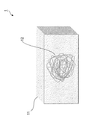
本発明の別の一態様は、三次元網状の微小流路を有する微小流路構造体に関する。本態様に係る微小流路構造体の一実施形態を図1に示す。図1に示すように、本態様に係る微小流路構造体1は、ゲル11と、該ゲル11中に微小流路12とを有する。本態様に係る微小流路構造体は、前記で説明した本発明の一態様に係る方法によって製造することができる。
<2: Microchannel structure with capillary network-like microchannels>
Another aspect of the present invention relates to a microchannel structure having a three-dimensional network microchannel. An embodiment of the microchannel structure according to this aspect is shown in FIG. As shown in FIG. 1, the
本態様に係る微小流路構造体は、1種以上のゲル化剤を含むゲルを有する。1種以上のゲル化剤は、前記で説明した本発明の一態様に係る方法で使用されるゲル化剤から適宜選択することができる。ゲルの形状及び寸法は、微小流路をその内部に配置できれば特に限定されない。本態様に係る微小流路構造体の用途等を考慮して、ゲルは、任意の形状及び寸法とすることができる。 The microchannel structure according to this embodiment has a gel containing one or more gelling agents. One or more gelling agents can be appropriately selected from the gelling agents used in the method according to one aspect of the present invention described above. The shape and size of the gel are not particularly limited as long as the microchannels can be arranged inside the gel. The gel can have any shape and size in consideration of the use of the microchannel structure according to this aspect.
本態様に係る微小流路構造体は、ゲル中に微小流路を有する。微小流路の具体的な形状は特に限定されない。微小流路の形状は、例えば、三次元網状又は綿飴状の形状である。微小流路の直径は、例えば2〜25 μmの範囲であり、通常は5〜20 μmの範囲であり、典型的には5〜15 μmの範囲であり、特に約10 μmである。また、隣接する微小流路の間の距離は、通常は50〜200 μmの範囲であり、典型的には50〜150 μmの範囲であり、特に約100 μmである。前記の形状及び寸法は、毛細血管網と同様の形状及び寸法を有する。それ故、本態様に係る方法によって得られる微小流路構造体は、人工臓器を作製する際に毛細血管網として使用することができる。 The microchannel structure according to this embodiment has microchannels in the gel. The specific shape of the microchannel is not particularly limited. The shape of the microchannel is, for example, a three-dimensional net-like shape or a cotton candy-like shape. The diameter of the microchannels is, for example, in the range of 2 to 25 μm, usually in the range of 5 to 20 μm, typically in the range of 5 to 15 μm, especially about 10 μm. Also, the distance between adjacent microchannels is usually in the range of 50-200 μm, typically in the range of 50-150 μm, especially about 100 μm. The shape and dimensions are similar to those of the capillary network. Therefore, the microchannel structure obtained by the method according to this embodiment can be used as a capillary network when producing an artificial organ.
以下、実施例を用いて本発明をさらに具体的に説明する。但し、本発明の技術的範囲はこれら実施例に限定されるものではない。 Hereinafter, the present invention will be described in more detail with reference to Examples. However, the technical scope of the present invention is not limited to these examples.
<I:微小流路構造体の製造>
[I-1:ゼラチン芯鞘繊維の紡糸]
ゼラチン(Gelatin from porcine skin (Type A)、シグマ-アルドリッチ社)を用いて、10 w/v% ゼラチン水溶液を、芯成分として調製した。また、1 w/v% アルギン酸ナトリウム水溶液を、鞘成分として調製した。同心円状に配設された2個の吐出口を有する二重円筒管形状のダイ(中心部吐出口径:0.48 mm、外周部吐出口径:0.94 mm)を準備して、中心部吐出口に接続された内筒及び外周部吐出口に接続された外筒に、それぞれシリンジを接続した。ダイの中心部吐出口及び外周部吐出口は、市販のシリンジ針(テルモシリンジ、テルモ社)を用いて作製した(図2B)。内筒に接続されたシリンジに芯成分(80℃)を、外筒に接続されたシリンジに鞘成分(20℃)を、それぞれ注入した。シリンジポンプを用いて、中心部吐出口から80℃に維持した芯成分を、外周部吐出口から20℃に維持した鞘成分を、それぞれ所定の押出流量で吐出しながら(芯成分及び鞘成分の総押出流量:3 ml/分)、約4℃の100 mM 塩化カルシウム水溶液中に共押出した。アルギン酸の2個のカルボキシル基は、1個のカルシウムイオンを介してイオン架橋し得る。このため、鞘成分に含まれるアルギン酸は、塩化カルシウム水溶液中に共押出されてゲル化する。また、芯成分に含まれるゼラチンは、低温の塩化カルシウム水溶液中に共押出されてゲル化する。それ故、塩化カルシウム水溶液中に共押出された芯成分及び鞘成分は、ゼラチン芯鞘繊維を形成した。形成されたゼラチン芯鞘繊維を、900 cm/分の引取速度で、吐出口から30 cmの位置に配置した巻取軸(直径:7.5 cm)に巻き取りながら、塩化カルシウム水溶液から引取紡糸した(図2A)。共押出における芯成分及び鞘成分の総押出流量に対する芯成分の押出流量の比(押出流量比)と、結果として得られたゼラチン芯鞘繊維の芯部の直径との関係を図3に示す。図中、黒塗り四角は、ゼラチン芯鞘繊維の直径を、黒塗り丸は、ゼラチン芯鞘繊維の芯部の直径を、それぞれ示す。また、位相差顕微鏡(DM IL LED、ライカ社)を用いて、得られたゼラチン芯鞘繊維を観察した。得られたゼラチン芯鞘繊維の写真を図4に示す。図中、Aは、押出流量比が0.167の場合に得られたゼラチン芯鞘繊維であり、寸法線は、ゼラチン芯鞘繊維の芯部の直径を表す。Bは、押出流量比が0.000833の場合に得られたゼラチン芯鞘繊維であり、矢印は、ゼラチン芯鞘繊維を表す。
<I: Manufacture of microchannel structure>
[I-1: Spinning of gelatin core sheath fiber]
Using gelatin (Gelatin from porcine skin (Type A), Sigma-Aldrich), a 10 w / v% gelatin aqueous solution was prepared as a core component. In addition, a 1 w / v% sodium alginate aqueous solution was prepared as a sheath component. Prepare a double cylindrical tube-shaped die (center discharge port diameter: 0.48 mm, outer circumference discharge port diameter: 0.94 mm) having two discharge ports arranged concentrically, and connect to the center discharge port. Syringes were connected to the inner cylinder and the outer cylinder connected to the outer peripheral discharge port, respectively. The central discharge port and the outer peripheral discharge port of the die were manufactured using a commercially available syringe needle (Terumo Syringe, Terumo Corporation) (Fig. 2B). The core component (80 ° C.) was injected into the syringe connected to the inner cylinder, and the sheath component (20 ° C.) was injected into the syringe connected to the outer cylinder. Using a syringe pump, the core component maintained at 80 ° C from the central discharge port and the sheath component maintained at 20 ° C from the outer peripheral discharge port are discharged at a predetermined extrusion flow rate (core component and sheath component). Total extrusion flow rate: 3 ml / min), coextruded into 100 mM calcium chloride aqueous solution at about 4 ° C. The two carboxyl groups of alginic acid can be ionic crosslinked via a single calcium ion. Therefore, alginic acid contained in the sheath component is co-extruded into an aqueous calcium chloride solution to gel. In addition, gelatin contained in the core component is co-extruded into a low-temperature calcium chloride aqueous solution to gel. Therefore, the core component and the sheath component co-extruded into the calcium chloride aqueous solution formed gelatin core-sheath fibers. The formed gelatin core-sheath fiber was taken up and spun from the calcium chloride aqueous solution while being taken up on a take-up shaft (diameter: 7.5 cm) arranged at a position of 30 cm from the discharge port at a take-up speed of 900 cm / min ( Figure 2A). FIG. 3 shows the relationship between the ratio of the extrusion flow rate of the core component to the total extrusion flow rate of the core component and the sheath component in coextrusion (extrusion flow rate ratio) and the diameter of the core portion of the resulting gelatin core-sheath fiber. In the figure, the black-painted square indicates the diameter of the gelatin core-sheath fiber, and the black-painted circle indicates the diameter of the core of the gelatin core-sheath fiber. In addition, the obtained gelatin core-sheath fiber was observed using a phase-contrast microscope (DM IL LED, Leica). A photograph of the obtained gelatin core-sheath fiber is shown in FIG. In the figure, A is a gelatin core-sheath fiber obtained when the extrusion flow rate ratio is 0.167, and the dimension line represents the diameter of the core portion of the gelatin core-sheath fiber. B is the gelatin core-sheath fiber obtained when the extrusion flow rate ratio is 0.000833, and the arrow represents the gelatin core-sheath fiber.
図3に示すように、押出流量比が大きくなるほど、ゼラチン芯鞘繊維の芯部の直径が大きくなった。押出流量比が0.000833以下、特に0.0000587〜0.000833の範囲では、ゼラチン芯鞘繊維の芯部の直径が25 μm以下となった(図4B)。これに対し、押出流量比が0.05を超えると、ゼラチン芯鞘繊維の芯部の直径が100 μm以上となった(図4A)。 As shown in FIG. 3, the larger the extrusion flow rate ratio, the larger the diameter of the core portion of the gelatin core-sheath fiber. When the extrusion flow rate ratio was 0.000833 or less, especially in the range of 0.0000587 to 0.000833, the diameter of the core of the gelatin core sheath fiber was 25 μm or less (Fig. 4B). On the other hand, when the extrusion flow rate ratio exceeded 0.05, the diameter of the core of the gelatin core-sheath fiber became 100 μm or more (Fig. 4A).
前記手順において、芯成分及び鞘成分の総押出流量、押出流量比及び引取速度を変更した他は、前記と同様にゼラチン芯鞘繊維紡糸工程を実施した。ゼラチン芯鞘繊維紡糸工程の条件と得られたゼラチン芯鞘繊維の芯部の直径とを表1に示す。 In the above procedure, the gelatin core-sheath fiber spinning step was carried out in the same manner as described above, except that the total extrusion flow rate, the extrusion flow rate ratio and the take-up speed of the core component and the sheath component were changed. Table 1 shows the conditions of the gelatin core-sheath fiber spinning process and the diameter of the core of the obtained gelatin core-sheath fiber.
表1に示すように、ゼラチン芯鞘繊維紡糸工程における芯成分及び鞘成分の総押出流量、押出流量比及び引取速度と、結果として得られるゼラチン芯鞘繊維の芯部の直径との間には一定の相関関係が存在することが明らかとなった。この相関関係は、下記の式:
Dは、ゼラチン芯鞘繊維の芯部の直径(cm)であり、
Qは、芯成分及び鞘成分の総押出流量(ml/分)であり、
Rは、押出流量比であり、
vは、ゼラチン芯鞘繊維の引取速度(cm/分)であり、
πは、円周率である。]
で表される。
As shown in Table 1, between the total extrusion flow rate, extrusion flow rate ratio and take-up rate of the core component and the sheath component in the gelatin core-sheath fiber spinning process and the diameter of the core portion of the resulting gelatin core-sheath fiber. It became clear that there was a certain correlation. This correlation is based on the following formula:
D is the diameter (cm) of the core of the gelatin core sheath fiber.
Q is the total extrusion flow rate (ml / min) of the core component and sheath component.
R is the extrusion flow rate ratio
v is the take-up rate (cm / min) of gelatin core sheath fiber,
π is the pi. ]
It is represented by.
比較例として、特許文献1に記載の方法に基づきゼラチン繊維を紡糸した。1 w/v% アルギン酸ナトリウム及び10 w/v% ゼラチン(ゲル化タンパク質)を含む水溶液を繊維成分として調製した。市販のシリンジ針(テルモシリンジ、テルモ社)を用いて、1個の吐出口を有するダイ(吐出口径:0.48 mm)を準備して、吐出口に接続されたシリンジに繊維成分(80℃)を注入した。シリンジポンプを用いて、吐出口から80℃に維持した繊維成分を所定の押出流量で吐出しながら、約4℃の100 mM 塩化カルシウム水溶液中に押出した。塩化カルシウム水溶液中に押出された繊維成分は、ゼラチン繊維を形成した。形成されたゼラチン繊維を、所定の引取速度で巻取軸(直径:7.5 cm)に巻き取りながら、塩化カルシウム水溶液から引取紡糸した。得られたゼラチン繊維の直径は、200 μm以上となった。ゼラチン繊維の直径を減少させるために、押出流量及び引取速度を調整したが、引取中に繊維が破断して、繊維を紡糸できなかった。
As a comparative example, gelatin fibers were spun based on the method described in
[I-2:ゼラチン繊維の形成]
I-1で得られた実施例1(2)のゼラチン芯鞘繊維(芯部の直径:11 μm、長さ:2×10³m)を、4℃の蒸留水で洗浄した。次に、ゼラチン芯鞘繊維を、4℃の5000 mLの100 mM クエン酸水溶液(pH 7.4)に48時間浸漬した。クエン酸とゼラチン芯鞘繊維の鞘部に含まれるカルシウムイオンとは、キレート錯体を形成する。このため、ゼラチン芯鞘繊維をクエン酸水溶液に浸漬させることにより、鞘部に含まれるアルギン酸カルシウムのイオン架橋が切断されて、鞘部が溶解する。それ故、ゼラチン芯鞘繊維の鞘部が溶解して、ゼラチン繊維が形成された。クエン酸水溶液からゼラチン繊維を取り出し、4℃の蒸留水で洗浄した。ゼラチン繊維を、4℃の99 v/v%エタノールに24時間浸漬して脱水した。次いで、ゼラチン繊維を、30℃のtert-ブチルアルコールに浸漬した。ゼラチン繊維を含むtert-ブチルアルコール混合物を4℃に冷却して凍結させた。この混合物を凍結乾燥して、ゼラチン繊維(0.06 g)を得た。実体顕微鏡(SMZ1500、ニコン社)及び走査型電子顕微鏡(SEM)(S-3000N、日立ハイテクノロジーズ社)を用いて、得られたゼラチン繊維を観察した。得られたゼラチン繊維の写真を図5に示す。図中、Aは、ゼラチン繊維の全体の外観を示す写真であり、Bは、ゼラチン繊維の拡大写真である。
[I-2: Formation of gelatin fiber]
The gelatin core-sheath fibers of Example 1 (2) obtained in I-1 (core diameter: 11 μm, length: 2 × 10 3 m) were washed with distilled water at 4 ° C. The gelatin core-sheath fiber was then immersed in 5000 mL of 100 mM citric acid aqueous solution (pH 7.4) at 4 ° C. for 48 hours. Citric acid and calcium ions contained in the sheath portion of the gelatin core sheath fiber form a chelate complex. Therefore, by immersing the gelatin core sheath fiber in the citric acid aqueous solution, the ion cross-linking of calcium alginate contained in the sheath portion is cut, and the sheath portion is dissolved. Therefore, the sheath portion of the gelatin core sheath fiber was dissolved to form the gelatin fiber. Gelatin fibers were removed from the aqueous citric acid solution and washed with distilled water at 4 ° C. Gelatin fibers were dehydrated by immersing them in 99 v / v% ethanol at 4 ° C. for 24 hours. The gelatin fibers were then immersed in tert-butyl alcohol at 30 ° C. The tert-butyl alcohol mixture containing gelatin fibers was cooled to 4 ° C and frozen. The mixture was lyophilized to give gelatin fibers (0.06 g). The obtained gelatin fibers were observed using a stereomicroscope (SMZ1500, Nikon Corporation) and a scanning electron microscope (SEM) (S-3000N, Hitachi High-Technologies Corporation). A photograph of the obtained gelatin fiber is shown in FIG. In the figure, A is a photograph showing the overall appearance of the gelatin fiber, and B is an enlarged photograph of the gelatin fiber.
図5Aに示すように、得られたゼラチン繊維は、三次元網状又は綿飴状の形状を有していた。図5Bに示すSEM写真に基づき測定したところ、ゼラチン繊維の直径の平均値は、10±2 μm(n=50)であった。三次元網状又は綿飴状の形状を有するゼラチン繊維において、隣接するゼラチン繊維の間の距離の平均値は、88±68 μm(n=50)であった。 As shown in FIG. 5A, the obtained gelatin fibers had a three-dimensional net-like or cotton candy-like shape. As a result of measurement based on the SEM photograph shown in FIG. 5B, the average value of the diameters of gelatin fibers was 10 ± 2 μm (n = 50). In gelatin fibers having a three-dimensional net-like or cotton candy-like shape, the average value of the distances between adjacent gelatin fibers was 88 ± 68 μm (n = 50).
[I-3:線状の微小流路を有する微小流路構造体の作製]
線状の微小流路を有する微小流路構造体の作製の概略を図6に示す。I-1及びI-2において、芯成分として使用するゼラチン水溶液に、1 μmの直径を有する蛍光標識ポリスチレン微粒子(Fluoresbrite Carboxylate Microspheres、カタログ番号:15702、Polysciences社)を0.1w/v%の濃度で添加した他は、実施例1と同様の手順及び条件で、蛍光標識ポリスチレン微粒子を含有するゼラチン繊維(直径:10μm、長さ:5×102m)を得た。このゼラチン繊維を切断して、3 cmの繊維片を得た。0.3% Cellmatrix(登録商標) Type I-A コラーゲン水溶液(新田ゼラチン社)、10倍濃度のイーグル最小必須培地及び再構成用緩衝液(47.7 g/L HEPES、1 M 水酸化ナトリウム及び22 g/L 炭酸水素ナトリウムを含む水溶液)を、約4℃の氷水中で冷却しながら8:1:1の割合(体積比)で混合して、コラーゲン混合液(pH 7.4)を得た。円形プラスチックシャーレ(10 cm)に、蛍光標識ポリスチレン微粒子を含有するゼラチン繊維片を静置した。このシャーレに、4℃の2 mLのコラーゲン混合液を入れて、4℃でゼラチン繊維片をコラーゲンに浸漬した。
[I-3: Fabrication of microchannel structure with linear microchannels]
FIG. 6 shows an outline of the production of a microchannel structure having linear microchannels. In I-1 and I-2, fluorescently labeled polystyrene fine particles (Fluoresbrite Carboxylate Microspheres, Catalog No .: 15702, Polysciences) having a diameter of 1 μm were added to the gelatin aqueous solution used as the core component at a concentration of 0.1 w / v%. Gelatin fibers (diameter: 10 μm, length: 5 × 10 2 m) containing fluorescently labeled polystyrene fine particles were obtained under the same procedure and conditions as in Example 1 except for the addition. This gelatin fiber was cut to obtain a 3 cm piece of fiber. 0.3% Cellmatrix® Type IA Aqueous Collagen (Nitta Gelatin), 10x Eagle Minimum Essential Medium and Reconstitution Buffer (47.7 g / L HEPES, 1 M Sodium Hydroxide and 22 g / L Carbonate An aqueous solution containing sodium hydrogen hydrogen) was mixed in an ice water at about 4 ° C. at a ratio of 8: 1: 1 (volume ratio) to obtain a collagen mixed solution (pH 7.4). Gelatin fiber pieces containing fluorescently labeled polystyrene fine particles were allowed to stand in a circular plastic petri dish (10 cm). A 2 mL collagen mixture at 4 ° C was placed in this petri dish, and gelatin fiber pieces were immersed in collagen at 4 ° C.
コラーゲンに浸漬されたゼラチン繊維片を含む円形シャーレを、20℃で20分間静置した。コラーゲンがゲル化して、蛍光標識ポリスチレン微粒子を含有するゼラチン繊維片がコラーゲンゲルに包埋された。次いで、コラーゲンゲルに包埋された蛍光標識ポリスチレン微粒子を含有するゼラチン繊維片を含む円形シャーレを、37℃のインキュベーターに入れて、37℃で20分間静置した。ゼラチン繊維片に含まれるゼラチンの溶解が進行した。これにより、コラーゲンゲル中に、ゼラチン繊維片を鋳型とする微小流路が形成されて、コラーゲンゲルと、該ゲル中に線状の微小流路を有する微小流路構造体を得た。蛍光顕微鏡(ECLIPSE Ti、ニコン社)を用いて、得られた微小流路構造体を観察した。微小流路構造体の蛍光顕微鏡写真を図7に示す。また、蛍光顕微鏡を用いて、蛍光粒子を含有するゼラチン繊維片及び得られた微小流路の直径を数カ所測定し、平均値を算出した。結果を表2に示す。 A circular petri dish containing gelatin fiber pieces soaked in collagen was allowed to stand at 20 ° C. for 20 minutes. Collagen gelled, and gelatin fiber pieces containing fluorescently labeled polystyrene fine particles were embedded in the collagen gel. Next, a circular petri dish containing gelatin fiber pieces containing fluorescently labeled polystyrene fine particles embedded in collagen gel was placed in an incubator at 37 ° C. and allowed to stand at 37 ° C. for 20 minutes. The dissolution of gelatin contained in the gelatin fiber pieces proceeded. As a result, microchannels using gelatin fiber pieces as a template were formed in the collagen gel, and a collagen gel and a microchannel structure having linear microchannels in the gel were obtained. The obtained microchannel structure was observed using a fluorescence microscope (ECLIPSE Ti, Nikon Corporation). A fluorescence micrograph of the microchannel structure is shown in FIG. In addition, using a fluorescence microscope, the diameters of the gelatin fiber pieces containing the fluorescent particles and the obtained microchannels were measured at several points, and the average value was calculated. The results are shown in Table 2.
図7に示すように、コラーゲンゲル中に、蛍光標識ポリスチレン微粒子が流動する微小流路が形成された。形成された微小流路の直径は、鋳型として使用したゼラチン繊維片の直径と略同一であった。 As shown in FIG. 7, microchannels through which fluorescently labeled polystyrene fine particles flow were formed in the collagen gel. The diameter of the formed microchannel was substantially the same as the diameter of the gelatin fiber piece used as the template.
[I-4:毛細血管網様の微小流路を有する微小流路構造体の作製]
毛細血管網様の微小流路を有する微小流路構造体の作製の概略を図8に示す。図8に示すように、透明プラスチック容器(開口:3 cm×0.5 cm、深さ:2 cm)の側面に、0.7 mmの外径及び70 mmの長さの2本のステンレス針(テルモシリンジ、テルモ社)を貫通させた。2本のステンレス針は、互いに及びプラスチック容器の底面と平行となるように、且つ深さ方向に一定の間隔(1.3 cm)で互いに離間するように配置した。I-1及びI-2の手順にしたがって得られた実施例1の三次元網状又は綿飴状のゼラチン繊維(直径:10 μm、長さ:2×10³m、質量:0.06 g)を、2本の針に接するようにプラスチック容器の内部に配置した。プラスチック容器に、I-3と同様の手順で調製した4℃のコラーゲン混合液(pH 7.4)を入れて、4℃でゼラチン繊維をコラーゲンに浸漬した。コラーゲンに浸漬されたゼラチン繊維を含むプラスチック容器を、20℃で20分間静置した。コラーゲンがゲル化して、ゼラチン繊維がコラーゲンゲルに包埋された。次いで、コラーゲンゲルに包埋されたゼラチン繊維を含むプラスチック容器を、37℃のインキュベーターに入れて、37℃で20分間静置した。ゼラチン繊維に含まれるゼラチンの溶解が進行した。これにより、コラーゲンゲル中に、ゼラチン繊維を鋳型とする微小流路が形成されて、コラーゲンゲルと、該ゲル中に三次元網状の微小流路を有する微小流路構造体を得た。
[I-4: Preparation of microchannel structure having capillary network-like microchannels]
FIG. 8 shows an outline of the production of a microchannel structure having a capillary network-like microchannel. As shown in Figure 8, on the side of a clear plastic container (opening: 3 cm x 0.5 cm, depth: 2 cm), two stainless needles (terumo syringe,) with an outer diameter of 0.7 mm and a length of 70 mm. Terumo) was penetrated. The two stainless needles were placed parallel to each other and to the bottom of the plastic container and at regular intervals (1.3 cm) in the depth direction. The three-dimensional net-like or cotton candy-like gelatin fibers (diameter: 10 μm, length: 2 × 10 3 m, mass: 0.06 g) of Example 1 obtained according to the procedures of I-1 and I-2 were used. It was placed inside the plastic container so that it touched the two needles. A 4 ° C collagen mixture (pH 7.4) prepared in the same procedure as I-3 was placed in a plastic container, and gelatin fibers were immersed in collagen at 4 ° C. A plastic container containing gelatin fibers soaked in collagen was allowed to stand at 20 ° C. for 20 minutes. Collagen gelled and gelatin fibers were embedded in the collagen gel. Then, a plastic container containing gelatin fibers embedded in collagen gel was placed in an incubator at 37 ° C. and allowed to stand at 37 ° C. for 20 minutes. The dissolution of gelatin contained in the gelatin fiber proceeded. As a result, microchannels using gelatin fibers as a template were formed in the collagen gel, and a collagen gel and a microchannel structure having a three-dimensional network-like microchannel in the gel were obtained.
2本の針をプラスチック容器から穏やかに引き抜いた。針を引き抜いたプラスチック容器の貫通孔のうち、右下方の1カ所から、シリンジを用いてヘパリン処理したラットの血液を注入した。ラットの血液を注入した毛細血管網様の微小流路を有する微小流路構造体の外観を示す写真を図9に示す。図中、Aは、注入開始5秒後、Bは、注入開始10秒後の写真である。図9に示すように、注入開始10秒後に、ラットの血液は、微小流路構造体の内部の微小流路の略全体に亘って流通した。
The two needles were gently pulled out of the plastic container. Heparinized rat blood was injected using a syringe from one of the through holes in the plastic container from which the needle was pulled out. FIG. 9 shows a photograph showing the appearance of a microchannel structure having a capillary network-like microchannel in which rat blood was injected. In the figure, A is a
1…微小流路構造体
11…ゲル
12…微小流路
21…芯成分と鞘成分とを共押出する手段
22…繊維形成液槽
23…引取手段
24…中心部吐出口
25…外周部吐出口
26…芯成分押出手段
27…鞘成分押出手段
1 ... Microchannel structure
11 ... Gel
12 ... Microchannel
21 ... Means for coextruding core component and sheath component
22… Fiber forming liquid tank
23… Means of collection
24 ... Central discharge port
25 ... Outer peripheral discharge port
26 ... Core component extrusion means
27… Sheath component extrusion means
Claims (8)
ゼラチン芯鞘繊維とキレート剤又はアルギン酸加水分解酵素であるアルギン酸除去剤とを接触させて、アルギン酸の二価陽イオン塩を含む鞘部を溶解させて2〜25 μmの直径を有するゼラチン繊維を得る、ゼラチン繊維形成工程;
ゼラチン繊維を、コラーゲン及びフィブリンからなる群より選択される1種以上のゲル化剤に浸漬する、浸漬工程;
ゼラチン繊維を浸漬したゲル化剤をゲル化して、ゼラチン繊維をゲルに包埋する、ゲル化工程;及び
ゲルに包埋されたゼラチン繊維を、25℃を超える温度で溶解させて、微小流路をゲル中に形成させる、微小流路形成工程;
を含み、
ゼラチン芯鞘繊維紡糸工程が、下記の式:
Dは、ゼラチン芯鞘繊維紡糸工程によって得られるゼラチン芯鞘繊維の芯部の直径(cm)であり、
Qは、芯成分及び鞘成分の総押出流量(ml/分)であり、
Rは、芯成分及び鞘成分の総押出流量に対する芯成分の押出流量の比であり、
vは、ゼラチン芯鞘繊維の引取速度(cm/分)であり、
πは、円周率である。]
で表される関係を満たす条件で実施される、前記ゲルとゲル中に2〜25 μmの範囲の直径の三次元網状の微小流路とを有する、微小流路構造体の製造方法。 The core component containing gelatin and the sheath component containing an alkali metal salt of alginic acid are coextruded into a fiber-forming liquid containing divalent cations at a temperature of 25 ° C. or lower, and the core containing gelatin and the divalent alginic acid are coextruded. A gelatin core-sheath fiber spinning step in which a gelatin core-sheath fiber having a sheath containing a cation salt is taken from a fiber-forming liquid and spun.
The gelatin core sheath fiber is brought into contact with a chelating agent or an alginic acid removing agent which is an alginic acid hydrolyzing enzyme to dissolve the sheath containing the divalent cation salt of alginic acid to obtain a gelatin fiber having a diameter of 2 to 25 μm. , Gelatin fiber forming step;
Immersion step of immersing gelatin fibers in one or more gelling agents selected from the group consisting of collagen and fibrin;
A gelling step in which a gelling agent in which gelatin fibers are immersed is gelled and the gelatin fibers are embedded in a gel; and the gelatin fibers embedded in the gel are dissolved at a temperature exceeding 25 ° C. to form a microchannel. To form a microchannel in the gel;
Including
The gelatin core-sheath fiber spinning process is based on the following formula:
D is the diameter (cm) of the core of the gelatin core-sheath fiber obtained by the gelatin core- sheath fiber spinning process .
Q is the total extrusion flow rate (ml / min) of the core component and sheath component.
R is the ratio of the extrusion flow rate of the core component to the total extrusion flow rate of the core component and the sheath component.
v is the take-up rate (cm / min) of gelatin core sheath fiber,
π is the pi. ]
A method for producing a microchannel structure, which comprises the gel and a three-dimensional network microchannel having a diameter in the range of 2 to 25 μm in the gel, which is carried out under the condition of satisfying the relationship represented by.
ゼラチン芯鞘繊維の芯部の直径Dが、2〜25 μmの範囲であり、
芯成分及び鞘成分の総押出流量Qが、0.5〜6 ml/分の範囲であり、
芯成分及び鞘成分の総押出流量に対する芯成分の押出流量の比Rが、0.0000293〜0.00283の範囲であり、且つ
ゼラチン芯鞘繊維の引取速度vが、300〜900 cm/分の範囲である、請求項1に記載の方法。 In the gelatin core sheath fiber spinning process
The diameter D of the core of the gelatin core sheath fiber is in the range of 2 to 25 μm.
The total extrusion flow rate Q of the core component and the sheath component is in the range of 0.5 to 6 ml / min.
The ratio R of the extrusion flow rate of the core component to the total extrusion flow rate of the core component and the sheath component is in the range of 0.0000293 to 0.00283, and the take-up speed v of the gelatin core and sheath fiber is in the range of 300 to 900 cm / min. The method according to claim 1.
Priority Applications (1)
| Application Number | Priority Date | Filing Date | Title |
|---|---|---|---|
| JP2016115661A JP6782002B2 (en) | 2016-06-09 | 2016-06-09 | Method for manufacturing a microchannel structure having a capillary network-like microchannel |
Applications Claiming Priority (1)
| Application Number | Priority Date | Filing Date | Title |
|---|---|---|---|
| JP2016115661A JP6782002B2 (en) | 2016-06-09 | 2016-06-09 | Method for manufacturing a microchannel structure having a capillary network-like microchannel |
Publications (2)
| Publication Number | Publication Date |
|---|---|
| JP2017217323A JP2017217323A (en) | 2017-12-14 |
| JP6782002B2 true JP6782002B2 (en) | 2020-11-11 |
Family
ID=60658587
Family Applications (1)
| Application Number | Title | Priority Date | Filing Date |
|---|---|---|---|
| JP2016115661A Active JP6782002B2 (en) | 2016-06-09 | 2016-06-09 | Method for manufacturing a microchannel structure having a capillary network-like microchannel |
Country Status (1)
| Country | Link |
|---|---|
| JP (1) | JP6782002B2 (en) |
Families Citing this family (1)
| Publication number | Priority date | Publication date | Assignee | Title |
|---|---|---|---|---|
| CN110917119A (en) * | 2019-11-18 | 2020-03-27 | 南通大学 | Sodium alginate drug-loaded fiber with skin-core structure and preparation method thereof |
-
2016
- 2016-06-09 JP JP2016115661A patent/JP6782002B2/en active Active
Also Published As
| Publication number | Publication date |
|---|---|
| JP2017217323A (en) | 2017-12-14 |
Similar Documents
| Publication | Publication Date | Title |
|---|---|---|
| JP6710000B2 (en) | Micro fiber | |
| Hoch et al. | Bioprinting of artificial blood vessels: current approaches towards a demanding goal | |
| Wang et al. | In situ 3D bioprinting living photosynthetic scaffolds for autotrophic wound healing | |
| JP6439918B2 (en) | Method for producing three-dimensional cell structure | |
| JP6712220B2 (en) | Method for printing a tissue construct having an embedded vasculature | |
| CN106243376B (en) | A kind of silk fibroin nano-fiber porous support and preparation method thereof | |
| Zhang et al. | Inverse opal scaffolds for applications in regenerative medicine | |
| Hammer et al. | A facile method to fabricate hydrogels with microchannel-like porosity for tissue engineering | |
| CN103974727B (en) | Porous organization's support | |
| CN103990182A (en) | Three-dimensional scaffold material for bone tissue repair and preparation method thereof | |
| CN106237381B (en) | A kind of fibroin albumen micro nanometer fiber porous support and preparation method thereof | |
| JP5945802B2 (en) | Complex hepatocyte tissue body and method for producing the same | |
| CN104001208B (en) | Preparation method for biomacromolecule/chitin nanocrystalline composite scaffold material | |
| CN106729959A (en) | A kind of fibroin fiber antiseptic dressing and preparation method thereof | |
| CN106139246A (en) | A kind of regenerated silk azelon support and preparation method thereof | |
| CN102068716A (en) | Method for preparing tissue engineering frame | |
| CN105126242A (en) | Polymer coating microneedle patch convenient for antibiotic skin testing and preparation method thereof | |
| CN101143941A (en) | Cellulose/ soy protein composite sponge and preparing method thereof | |
| Li et al. | A novel method for fabricating engineered structures with branched micro-channel using hollow hydrogel fibers | |
| JP6782002B2 (en) | Method for manufacturing a microchannel structure having a capillary network-like microchannel | |
| CN106938057A (en) | A kind of fibroin fiber support and preparation method thereof | |
| CN101219238A (en) | Composite biological degradable synthesized polymer material | |
| CN103120808B (en) | Preparation method of three-dimensional soft bracket | |
| CN100475886C (en) | Method for preparing polymer material with gradient distributed surface biomacromolecule | |
| CN106543467B (en) | A kind of ice glue bracket and its preparation method and application |
Legal Events
| Date | Code | Title | Description |
|---|---|---|---|
| A621 | Written request for application examination |
Free format text: JAPANESE INTERMEDIATE CODE: A621 Effective date: 20190514 |
|
| A131 | Notification of reasons for refusal |
Free format text: JAPANESE INTERMEDIATE CODE: A131 Effective date: 20200310 |
|
| A977 | Report on retrieval |
Free format text: JAPANESE INTERMEDIATE CODE: A971007 Effective date: 20200306 |
|
| A521 | Request for written amendment filed |
Free format text: JAPANESE INTERMEDIATE CODE: A523 Effective date: 20200501 |
|
| TRDD | Decision of grant or rejection written | ||
| A01 | Written decision to grant a patent or to grant a registration (utility model) |
Free format text: JAPANESE INTERMEDIATE CODE: A01 Effective date: 20200915 |
|
| A61 | First payment of annual fees (during grant procedure) |
Free format text: JAPANESE INTERMEDIATE CODE: A61 Effective date: 20201012 |
|
| R150 | Certificate of patent or registration of utility model |
Ref document number: 6782002 Country of ref document: JP Free format text: JAPANESE INTERMEDIATE CODE: R150 |
|
| R250 | Receipt of annual fees |
Free format text: JAPANESE INTERMEDIATE CODE: R250 |