JP6780434B2 - Warm reducer - Google Patents
Warm reducer Download PDFInfo
- Publication number
- JP6780434B2 JP6780434B2 JP2016204198A JP2016204198A JP6780434B2 JP 6780434 B2 JP6780434 B2 JP 6780434B2 JP 2016204198 A JP2016204198 A JP 2016204198A JP 2016204198 A JP2016204198 A JP 2016204198A JP 6780434 B2 JP6780434 B2 JP 6780434B2
- Authority
- JP
- Japan
- Prior art keywords
- worm
- wheel element
- wheel
- peripheral surface
- axial direction
- Prior art date
- Legal status (The legal status is an assumption and is not a legal conclusion. Google has not performed a legal analysis and makes no representation as to the accuracy of the status listed.)
- Active
Links
Images


Landscapes
- Gear Transmission (AREA)
- Gears, Cams (AREA)
Description
本発明は、芯材となる内側ホイール素子と歯部を有する合成樹脂製の外側ホイール素子とを備えたウォームホイールを含んで構成されるウォーム減速機に関する。 The present invention relates to a worm reducer including a worm wheel including an inner wheel element serving as a core material and an outer wheel element made of synthetic resin having tooth portions.
図10〜15は、特許文献1等に記載されて従来から知られている電動式パワーステアリング装置の1例を示している。後端部にステアリングホイール1を取り付けられたステアリングシャフト2の前端部は、ハウジング3内に回転自在に支持されており、このステアリングシャフト2により回転駆動される部分にウォームホイール4が固定されている。一方、電動モータ5の出力軸にはウォーム軸6が連結されている。そして、このウォーム軸6の軸方向中間部外周面に設けられたウォーム歯部18と、前記ウォームホイール4の外周面に設けられたウォームホイール歯部19とを噛合させる事により、前記電動モータ5から前記ウォームホイール4に対して、所定方向に所定の大きさの補助トルク(補助動力)を付与する事が可能となっている。
FIGS. 10 to 15 show an example of an electric power steering device described in Patent Document 1 and the like and conventionally known. The front end portion of the
前記ウォームホイール4は、補助トルクの出力部となる出力軸7の軸方向中間部に外嵌固定されており、この出力軸7と共に回転する。この出力軸7は、前記ハウジング3内に、軸方向中間部の両端寄り部分を1対の転がり軸受8a、8bにより回転のみ可能に支持された状態で、トーションバー9を介して、前記ステアリングシャフト2の前端部に結合されている。前記電動モータ5は、トルクセンサ10が検出する、前記ステアリングホイール1から前記ステアリングシャフト2に加えられる操舵トルクの方向及び大きさに応じて前記ウォーム軸6を回転駆動し、前記出力軸7に補助トルクを付与する。この出力軸7の回転は、1対の自在継手11a、11b及び中間シャフト12を介して、ステアリングギヤユニット13の入力部となるピニオン軸14に伝達され、操舵輪に所望の舵角が付与される。
The worm wheel 4 is externally fitted and fixed to an axially intermediate portion of an
又、図示の例の場合、前記ウォームホイール4は、芯材となる金属製の内側ホイール素子15と、合成樹脂製の外側ホイール素子16とを組み合わせて成る。即ち、前記ウォームホイール4は、前記出力軸7に外嵌固定される部分を、金属製で円輪状の前記内側ホイール素子15とし、前記ウォームホイール歯部19を含む部分を、合成樹脂製の前記外側ホイール素子16としている。そして、この様に外側ホイール素子16を合成樹脂製とする事により、前記ウォームホイール4の外周面にウォームホイール歯部19を形成する作業の容易化(低コスト化)、及び、前記ウォーム軸6のウォーム歯部18と前記ウォームホイール4のウォームホイール歯部19との噛合部で発生する歯打ち音の低減を図れる様にしている。
Further, in the case of the illustrated example, the worm wheel 4 is formed by combining a metal
又、前記外側ホイール素子16は、合成樹脂製であり、射出成形に伴って(インサート成形により)、前記内側ホイール素子15の径方向外端部を全周に亙り包埋している。又、前記内側ホイール素子15の外周面には、円周方向に関する(歯車状の)凹凸部17が設けられており、この凹凸部17を構成する複数の凹部に前記外側ホイール素子16を構成する合成樹脂の一部を入り込ませる事で、前記内側ホイール素子15に対する前記外側ホイール素子16の回転方向の保持力を高めている。
Further, the
上述した様な従来構造の場合には、前記外側ホイール素子16の外周面に設けられたウォームホイール歯部19の製造誤差を低減する面から、改良の余地がある。
即ち、上述した従来構造の場合には、前記内側ホイール素子15の外周面に円周方向に関する凹凸部17を設けると共に、この凹凸部17を構成する複数の凹部に前記外側ホイール素子16を構成する合成樹脂の一部を入り込ませている。この為、前記外側ホイール素子16のうち、前記凹凸部17に対して径方向外側に重畳する部分の径方向の肉厚は、前記ウォームホイール歯部19を構成する複数の歯20、20が位置する部分ごとに、互いに異なった大きさになる場合がある(図14〜15参照)。この様な場合には、これら複数の歯20、20が位置する部分ごとに、射出成形時の成形収縮量が異なる{径方向の肉厚が大きい部分(例えば図15のα部)で大きくなり、径方向の肉厚が小さい部分(例えば図15のβ部)で小さくなる}為、成形後の前記複数の歯20、20の大きさに差が生じ、この事に起因して、前記ウォームホイール歯部19にピッチ誤差等の製造誤差が生じる可能性がある。
In the case of the conventional structure as described above, there is room for improvement from the viewpoint of reducing the manufacturing error of the worm
That is, in the case of the above-mentioned conventional structure, the outer peripheral surface of the
本発明は、上述の様な事情に鑑み、芯材となる内側ホイール素子に対する合成樹脂製の外側ホイール素子の保持力を確保しつつ、この外側ホイール素子の外周面に設けられるウォームホイール歯部のうち、ウォーム歯部と噛合する部分の製造誤差を抑えられる構造を実現すべく発明したものである。 In view of the above circumstances, the present invention secures the holding force of the outer wheel element made of synthetic resin with respect to the inner wheel element serving as the core material, and provides the worm wheel tooth portion provided on the outer peripheral surface of the outer wheel element. Of these, it was invented to realize a structure that can suppress manufacturing errors in the portion that meshes with the worm tooth portion.
本発明のウォーム減速機は、外周面にウォームホイール歯部を有するウォームホイールと、外周面にウォーム歯部を有し、このウォーム歯部を前記ウォームホイール歯部に噛合させたウォーム軸とを備える。このうちのウォーム軸は、例えばハウジングに対し回転自在に支持され、又、前記ウォームホイールは、例えば前記ハウジングに対し回転自在に支持された回転軸に外嵌固定される。
前記ウォームホイールは、内側ホイール素子と、外側ホイール素子とを有する。
このうちの内側ホイール素子は、円環状に構成され、軸方向側面のうちで外周縁よりも径方向内側に位置する部分に全周に亙り軸方向に凹む状態で設けられた環状凹部と、外周面と前記環状凹部との間に挟まれた部分に設けられた凹凸部とを有すると共に、外周面のうちで軸方向に関して前記凹凸部から外れた軸方向範囲の全体(この外周面の軸方向端縁部に面取り部が設けられる場合には、この面取り部を除く)が円筒面部になっている。尚、前記環状凹部は、例えば、前記内側ホイール素子の軸方向側面の径方向中間部や、この内側ホイール素子の軸方向側面の径方向中間部乃至内端部に設ける事ができる。
又、前記外側ホイール素子は、合成樹脂製で円環状に構成され、外周面に前記ウォームホイール歯部を有し、前記内側ホイール素子の径方向外端部を全周に亙り包埋していると共に、前記合成樹脂の一部が前記環状凹部と前記凹凸部を構成する凹部とに入り込んでいる。
又、前記ウォームホイール歯部と前記ウォーム歯部との噛合部の全体が、前記ウォームホイールの径方向に関して前記円筒面部と重畳している。換言すれば、前記円筒面部の軸方向に関する幅寸法が、前記噛合部の、前記ウォームホイールの軸方向に関する幅寸法以上になっていると共に、前記ウォームホイールの軸方向に関して、前記噛合部の位置する範囲が前記円筒面部の位置する範囲内に収まっている。
更に、前記円筒面部の軸方向に関する幅寸法が、前記ウォーム軸の軸方向に関して前記ウォームホイール歯部と前記ウォーム歯部とが重畳している領域(前記噛合部を含む領域)の、前記ウォームホイールの軸方向に関する幅寸法以上になっていると共に、前記ウォームホイールの軸方向に関して、前記領域の位置する範囲が前記円筒面部の位置する範囲内に収まっている。
The worm reducer of the present invention includes a worm wheel having a worm wheel tooth portion on the outer peripheral surface, and a worm shaft having a worm tooth portion on the outer peripheral surface and engaging the worm tooth portion with the worm wheel tooth portion. .. Of these, the worm shaft is rotatably supported by, for example, a housing, and the worm wheel is externally fitted and fixed to, for example, a rotating shaft rotatably supported by the housing.
The worm wheel has an inner wheel element and an outer wheel element.
Of these, the inner wheel element is formed in an annular shape, and has an annular recess provided in a state of being recessed in the axial direction over the entire circumference in a portion of the axial side surface located radially inside the outer peripheral edge, and an outer circumference. It has a concavo-convex portion provided in a portion sandwiched between the surface and the annular recess, and the entire axial range of the outer peripheral surface deviating from the concavo-convex portion in the axial direction (axial direction of the outer peripheral surface). If a chamfered portion is provided on the edge portion, this chamfered portion is excluded) is a cylindrical surface portion. The annular recess can be provided, for example, in the radial intermediate portion of the axial side surface of the inner wheel element, or in the radial intermediate portion or the inner end portion of the axial side surface of the inner wheel element.
Further, the outer wheel element is made of synthetic resin and is formed in an annular shape, has the worm wheel tooth portion on the outer peripheral surface, and embeds the radial outer end portion of the inner wheel element all around. At the same time, a part of the synthetic resin has entered the annular recess and the recess forming the uneven portion.
Further, the entire meshing portion between the worm wheel tooth portion and the worm tooth portion overlaps with the cylindrical surface portion in the radial direction of the worm wheel. In other words, the width dimension of the cylindrical surface portion with respect to the axial direction is equal to or greater than the width dimension of the meshing portion with respect to the axial direction of the worm wheel, and the meshing portion is located with respect to the axial direction of the worm wheel. The range is within the range where the cylindrical surface portion is located.
Further, the worm wheel in a region where the width dimension of the cylindrical surface portion in the axial direction overlaps the worm wheel tooth portion and the worm tooth portion in the axial direction of the worm shaft (region including the meshing portion). It is equal to or larger than the width dimension in the axial direction of the worm wheel, and the range where the region is located is within the range where the cylindrical surface portion is located in the axial direction of the worm wheel.
尚、本発明を実施する場合に、前記内側ホイール素子の材料としては、金属を採用できる他、例えば、前記外側ホイール素子の材料よりも耐熱性に優れ、この外側ホイール素子を射出成形する時の熱影響を受けにくい合成樹脂などを採用する(例えば、前記外側ホイール素子を構成する合成樹脂を熱可塑性樹脂とする一方で、前記内側ホイール素子を構成する合成樹脂を熱硬化性樹脂とする)事もできる。 In carrying out the present invention, a metal can be used as the material of the inner wheel element, and for example, it is superior in heat resistance to the material of the outer wheel element, and when the outer wheel element is injection-molded, for example. Use a synthetic resin that is not easily affected by heat (for example, the synthetic resin that constitutes the outer wheel element is a thermoplastic resin, while the synthetic resin that constitutes the inner wheel element is a thermosetting resin). You can also.
本発明のウォーム減速機を実施する場合には、例えば、前記凹凸部が、前記内側ホイール素子の軸方向側面のうちで径方向に関して外周面と前記環状凹部との間に挟まれた部分に設けられた円周方向に関する凹凸部である構成を採用する事ができる。
この場合には、例えば、前記凹凸部を構成する凹部の軸方向深さが、径方向内側に向かうに従って小さくなっている構成を採用する事ができる。
When implementing the worm reducer of the present invention, for example, the uneven portion is provided in a portion of the axial side surface of the inner wheel element sandwiched between the outer peripheral surface and the annular recess in the radial direction. It is possible to adopt a configuration that is an uneven portion in the circumferential direction.
In this case, for example, it is possible to adopt a configuration in which the axial depth of the concave portion constituting the concave-convex portion decreases toward the inner side in the radial direction.
本発明のウォーム減速機を実施する場合には、例えば、前記外側ホイール素子を構成する合成樹脂のうち前記環状凹部に入り込んだ部分が、この環状凹部の内面を構成する外径側周面からこの内面を構成する内径側周面までの連続した範囲を覆っている構成を採用する事ができる。 When the worm reducer of the present invention is implemented, for example, a portion of the synthetic resin constituting the outer wheel element that has entered the annular recess is formed from an outer diameter side peripheral surface that constitutes the inner surface of the annular recess. It is possible to adopt a configuration that covers a continuous range up to the inner peripheral side peripheral surface that constitutes the inner surface.
本発明のウォーム減速機を実施する場合には、例えば、前記環状凹部及び前記凹凸部が、前記内側ホイール素子の軸方向両側面に設けられている構成を採用する事ができる。 When implementing the worm reducer of the present invention, for example, it is possible to adopt a configuration in which the annular recess and the uneven portion are provided on both side surfaces in the axial direction of the inner wheel element.
本発明のウォーム減速機を実施する場合には、例えば、前記内側ホイール素子の表面のうち、前記外側ホイール素子を構成する合成樹脂により覆われる部分のうちの少なくとも一部分(例えば前記円筒面部、前記内側ホイール素子の表面全体)が、ローレット加工、シボ加工(硬質金属の表面に形成された微細な凹凸を成形品の表面に転写する加工)、ショットブラストなどの各種の加工によって形成された、微細な凹凸面になっている構成を採用する事ができる。
この様な構成を採用すれば、前記微細な凹凸面を構成する凹部に前記外側ホイール素子を構成する合成樹脂の一部が入り込む為、前記内側ホイール素子に対する前記外側ホイール素子の保持力(密着性)を高める事ができる。
尚、前記微細な凹凸面を構成する凹部の深さは、前記ウォームホイール歯部を構成する歯の径方向高さの1/10以下(好ましくは1/20以下、より好ましくは1/30以下)として、前記外側ホイール素子を構成する合成樹脂の体積に余り影響を与えない様にするのが好ましい。
When the worm reducer of the present invention is implemented, for example, at least a part of the surface of the inner wheel element covered with the synthetic resin constituting the outer wheel element (for example, the cylindrical surface portion, the inner side). The entire surface of the wheel element) is formed by various processes such as knurling, graining (processing to transfer fine irregularities formed on the surface of hard metal to the surface of the molded product), and shot blasting. It is possible to adopt a configuration having an uneven surface.
If such a configuration is adopted, a part of the synthetic resin constituting the outer wheel element enters the recess forming the fine uneven surface, so that the holding force (adhesion) of the outer wheel element with respect to the inner wheel element ) Can be increased.
The depth of the recesses forming the fine uneven surface is 1/10 or less (preferably 1/20 or less, more preferably 1/30 or less) of the radial height of the teeth constituting the worm wheel tooth portion. ), It is preferable that the volume of the synthetic resin constituting the outer wheel element is not significantly affected.
上述の様な構成を有する本発明のウォーム減速機によれば、内側ホイール素子に対する合成樹脂製の外側ホイール素子の保持力を確保しつつ、この外側ホイール素子の外周面に設けられるウォームホイール歯部のうち、ウォーム歯部と噛合する部分の製造誤差を抑えられる。 According to the worm reducer of the present invention having the above-described configuration, the worm wheel tooth portion provided on the outer peripheral surface of the outer wheel element while ensuring the holding force of the outer wheel element made of synthetic resin with respect to the inner wheel element. Of these, the manufacturing error of the part that meshes with the worm tooth part can be suppressed.
[参考例の第1例]
本発明に関連する参考例の第1例に就いて、図1〜5により説明する。
尚、本参考例に関する以下の説明中、軸方向に関して「片側」とは、図1及び図3の左側を言い、軸方向に関して「他側」とは、図1及び図3の右側を言う。
又、前後方向は、自動車の前後方向を意味する。
[First example of reference example ]
A first example of a reference example related to the present invention will be described with reference to FIGS. 1 to 5.
In the following description of this reference example, "one side" in the axial direction means the left side of FIGS. 1 and 3, and "the other side" in the axial direction means the right side of FIGS. 1 and 3.
Further, the front-rear direction means the front-rear direction of the automobile.
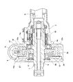
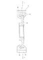
図1は、本参考例のウォーム減速機を組み込んだ電動式パワーステアリング装置を示している。後端部にステアリングホイール1(図10参照)を取り付けられたステアリングシャフト2の前端部は、ハウジング3内に回転自在に支持されており、このステアリングシャフト2により回転駆動される部分にウォームホイール4aが固定されている。一方、電動モータ5(図10〜12参照)の出力軸にはウォーム軸6が連結されている。そして、このウォーム軸6の軸方向中間部外周面に設けられたウォーム歯部18と、前記ウォームホイール4aの外周面に設けられたウォームホイール歯部19aとを噛合させる事により、前記電動モータ5から前記ウォームホイール4aに対して、所定方向に所定の大きさの補助トルク(補助動力)を付与する事が可能となっている。
FIG. 1 shows an electric power steering device incorporating the worm reducer of this reference example. The front end portion of the
前記ウォームホイール4aは、回転軸である、補助トルクの出力部となる出力軸7の軸方向中間部に外嵌固定されており、この出力軸7と共に回転する。この出力軸7は、前記ハウジング3内に、軸方向中間部の両端寄り部分を1対の転がり軸受8a、8bにより回転のみ可能に支持された状態で、トーションバー9を介して、前記ステアリングシャフト2の前端部に結合されている。前記電動モータ5は、トルクセンサ10が検出する、前記ステアリングホイール1から前記ステアリングシャフト2に加えられる操舵トルクの方向及び大きさに応じて前記ウォーム軸6を回転駆動し、前記出力軸7に補助トルクを付与する。この出力軸7の回転は、1対の自在継手11a、11b及び中間シャフト12を介して、ステアリングギヤユニット13の入力部となるピニオン軸14(図10参照)に伝達され、操舵輪に所望の舵角が付与される。
The
前記ウォームホイール4aは、内側ホイール素子15aと、外側ホイール素子16aとを組み合わせて成る。
The
前記内側ホイール素子15aは、金属製であり、断面コ字形の円環状(略円輪状)に造られている。この様な内側ホイール素子15aは、径方向中央部に、前記出力軸7の軸方向中間部をトルク伝達を可能に内嵌固定する為の嵌合孔21を有している。又、前記内側ホイール素子15aの軸方向片側面の径方向中間部には、全周に亙り、軸方向に凹む状態で環状凹部22が設けられている。この環状凹部22の内面を構成する外径側周面23及び内径側周面25は、それぞれ前記内側ホイール素子15aの中心軸に対して傾斜していない円筒面状に形成されている。又、前記環状凹部22の内面を構成する底面24は、前記内側ホイール素子15aの中心軸に対して直交する円輪面状に形成されている。又、前記外径側周面23の軸方向他端寄り部分には、全周に亙り、径方向外方に凹む状態で副凹部26が設けられている。
The
又、前記内側ホイール素子15aの軸方向他側面の径方向外端寄り部分には、全周に亙り、環状凹部22aが設けられている。この環状凹部22aの径方向に関する幅寸法及び軸方向に関する深さ寸法は、それぞれ前記内側ホイール素子15aの軸方向片側面に設けられた環状凹部22に比べて、小さくなっている。又、前記環状凹部22aの内面を構成する外径側周面23aは、前記内側ホイール素子15aの中心軸に対して傾斜していない円筒面状に形成されている。又、前記環状凹部22aの内面を構成する内径側周面25aは、前記環状凹部22aの軸方向開口側である軸方向他側に向かう程、この環状凹部22aの径方向に関する幅寸法が大きくなる方向である径方向内側に向かう方向に傾斜した部分円すい面状に形成されている。又、前記環状凹部22aの内面を構成する底面24aは、前記内側ホイール素子15aの中心軸に対して直交する円輪面状に形成されている。
Further, an
又、前記内側ホイール素子15aの軸方向片側面のうちで、径方向に関して外周面と前記環状凹部22との間に挟まれた部分には、全周に亙り、円周方向に関して凹部28と凸部29とを交互に(更には等ピッチに)配置して成る、円周方向に関する(側歯歯車状の)凹凸部27が設けられている。この凹凸部27を構成する各凹部28の底面は、前記内側ホイール素子15aの中心軸に対して直交する方向(放射方向)に形成されている。又、前記凹凸部27を構成する各凹部28は、前記内側ホイール素子15aの軸方向片側面に開口している事に加えて、この内側ホイール素子15aの外周面、及び、前記環状凹部22の内面を構成する外径側周面23にも、開口している。
Further, on one side surface of the
又、前記内側ホイール素子15aは、外周面のうちで、軸方向に関して前記凹凸部27から外れた軸方向範囲(軸方向中間部及び他端部)の全体(軸方向端縁部に面取り部が設けられる場合には、この面取り部を除く)が、前記内側ホイール素子15aの中心軸からの径方向距離が全周に亙り実質的に変化しない円筒面部30になっている。本参考例の場合、この円筒面部30は、前記ウォームホイール4aの中心軸と平行な母線を有し、軸方向に関して直径が変化しない単一円筒面状に形成されている。
Further, in the outer peripheral surface, the
又、本参考例の場合、別な言い方をすれば、前記内側ホイール素子15aは、互いに同心に配置された内径側環状部31及び外径側環状部32と、これら内径側環状部31の外周面と外径側環状部32の内周面とを連結する円輪状の連結部33とを備えている。そして、この連結部33の軸方向片側面と前記内径側環状部31の外周面と前記外径側環状部32の内周面とにより三方を囲まれた部分が前記環状凹部22になっており、前記外径側環状部32の軸方向他側面と前記連結部33の軸方向他側面とに跨る位置に前記環状凹部22aが設けられている。又、前記外径側環状部32の軸方向片側面が前記凹凸部27になっており、この外径側環状部32の外周面の軸方向中間部及び他端部が前記円筒面部30になっている。
Further, in the case of this reference example, in other words, the
尚、前記内側ホイール素子15aを構成する金属としては、鉄鋼等の鉄合金の他、銅合金、アルミニウム合金、マグネシウム合金等の各種の金属を採用する事ができる。又、前記内側ホイール素子15aを成形する為の加工としては、各種の切削加工や塑性加工を採用する事ができる。但し、歩留まり良く低コストに成形するには、塑性加工(鍛造、プレス、フローフォーミング等)を採用するのが好ましい。
As the metal constituting the
前記外側ホイール素子16aは、合成樹脂を射出成形する事により造られたもので、この射出成形に伴って(インサート成形により)、断面L字形に形成された前記内側ホイール素子15aの径方向外端部を、全周に亙り包埋している。この状態で、前記合成樹脂の一部は、前記環状凹部22の径方向外端部と、前記副凹部26の全体と、前記環状凹部22aの全体と、前記凹凸部27を構成する各凹部28の全体とに入り込んでいる。そして、前記合成樹脂のうち前記環状凹部22に入り込んだ部分が円環状の抑え部34を構成している。又、前記合成樹脂のうち前記副凹部26に入り込んだ部分が円環状の副抑え部35を構成している。又、前記合成樹脂のうち前記環状凹部22aに入り込んだ部分が円環状の抑え部34aを構成している。更に、前記合成樹脂のうち前記凹凸部27を構成する各凹部28に入り込んで、前記凹凸部27の表面全体を覆った部分が、この凹凸部27と係合する(この凹凸部27と合致する形状を有する)回転保持部36を構成している。
The
又、前記外側ホイール素子16aの外周面には、ウォームホイール歯部19aが形成されている。このウォームホイール歯部19aの軸方向中間部は、前記円筒面部30と径方向に重畳している。又、図示は省略するが、前記ウォームホイール歯部19aを構成する複数の歯20a、20aの形成方向は、前記ウォームホイール4aの軸方向に対して傾斜している。又、本参考例の場合、このウォームホイール歯部19aの歯先円の直径及び歯底円の直径は、それぞれ軸方向に関して変化していない。
Further, a worm
本参考例の場合、前記外側ホイール素子16aを射出成形により造るのと同時に、この外側ホイール素子16aを前記内側ホイール素子15aに対して結合する、インサート成形を実施する際には、例えば、前記内側ホイール素子15aを金型にセットする事により、これら内側ホイール素子15aの径方向外端部と金型の内面との間に円環状のキャビティ(前記外側ホイール素子16aが成形される空間)を形成すると共に、このキャビティの軸方向他側の径方向内端部にディスクゲートの径方向外端部を位置させる。そして、このディスクゲートを通じて、前記キャビティ内に合成樹脂を送り込む事により前記外側ホイール素子16aを成形する事ができる。
In the case of this reference example, when the
尚、前記外側ホイール素子16aを構成する合成樹脂としては、ポリアミド66(PA66)の他、ポリアミド46(PA46)、ポリアミド9T(PA9T)、ポリフェニレンサルファイド(PPS)、ポリエチレンテレフタレート(PET)、ポリアセタール(POM)等の各種の合成樹脂を採用する事ができる。又、これらの合成樹脂には、必要に応じて、ガラス繊維、ポリエチレン繊維、カーボン繊維、アラミド繊維等の各種の強化繊維を混入する事ができる。
As the synthetic resin constituting the
又、本参考例の場合には、前記ウォーム減速機を組み立てた状態で、前記ウォーム歯部18と前記ウォームホイール歯部19aとの噛合部37(図3に斜格子を付した部分)の全体を、前記内側ホイール素子15aの外周面に存在する前記円筒面部30と径方向に重畳させる構成を採用している。この為に、前記円筒面部30の軸方向幅寸法Tを、前記噛合部37の軸方向幅寸法S以上{T≧S(図3に示した例ではT>S)}にすると共に、前記噛合部37の位置する軸方向範囲を、前記円筒面部30の位置する軸方向範囲内に収めている。別な言い方をすれば、本参考例の場合には、前記内側ホイール素子15aの外周面のうち、少なくとも前記噛合部37の全体と径方向に重畳する軸方向範囲が、前記円筒面部30になっている。
Further, in the case of this reference example, in the state where the worm reducer is assembled, the entire meshing portion 37 (the portion provided with the oblique grid in FIG. 3) between the
上述の様に構成する本参考例のウォーム減速機によれば、金属製の内側ホイール素子15aに対する合成樹脂製の外側ホイール素子16aの保持力を確保しつつ、この外側ホイール素子16aの外周面に設けられるウォームホイール歯部19aのうち、ウォーム歯部18と噛合する部分の製造誤差を抑えられる。この点に就いて、以下に説明する。
According to the worm reducer of this reference example configured as described above, the outer peripheral surface of the
前記ウォームホイール4aを通じて前記出力軸7に補助トルクを付与する際には、前記ウォームホイール4aのウォームホイール歯部19aと前記ウォーム軸6のウォーム歯部18との噛合部37に作用する噛み合い反力の軸方向成分に基づいて、前記ウォームホイール4aに対し、図3に矢印で示す様に、倒れ方向のモーメントMが加わる。
When an auxiliary torque is applied to the
これに対して、本参考例の場合には、前記内側ホイール素子15aの軸方向両側面に、全周に亙り環状凹部22、22aが設けられている。これと共に、このうちの環状凹部22の内面を構成する外径側周面23に全周に亙り副凹部26が設けられている。そして、前記外側ホイール素子16aは、前記内側ホイール素子15aの径方向外端部を全周に亙り包埋していると共に、前記外側ホイール素子16aを構成する合成樹脂の一部が、前記環状凹部22の径方向外端部と前記環状凹部22aの全体と前記副凹部26の全体とに入り込んで、これら各箇所に入り込んだ部分が、それぞれ円環状の抑え部34、34a及び副抑え部35を構成している。この為、本参考例の場合には、前記内側ホイール素子15aに対する前記外側ホイール素子16aの前記モーメントM方向の保持力を確保できる。
On the other hand, in the case of this reference example,
尚、本参考例の場合には、前記環状凹部22aの内面を構成する内径側周面25aを前述した部分円すい面状に形成すると共に、この内面を構成する外径側周面23aを円筒面状に形成している。この為、前述した様に外側ホイール素子16aを射出成形する際には、前記ディスクゲートから前記キャビティ内に送り込まれた合成樹脂を、流れを乱す事なく、前記内径側周面(部分円すい面)25aに沿って前記環状凹部22aに入り込む事ができる。これと共に、前記外側ホイール素子16aを構成する抑え部34aと前記外径側周面(円筒面)23aとの係合強度を大きくして、前記モーメントM方向の保持力を高める事ができる。
In the case of this reference example, the inner diameter side
又、本参考例の場合には、前記内側ホイール素子15aの軸方向片側面の径方向外端部に円周方向に関する凹凸部27が設けられていると共に、前記外側ホイール素子16aを構成する合成樹脂の一部が、前記凹凸部27を構成する各凹部28の全体に入り込んで、前記凹凸部27の表面全体を覆う事により、この凹凸部27と係合する回転保持部36を構成している。この為、本参考例の場合には、前記内側ホイール素子15aに対する前記外側ホイール素子16aの回転方向の保持力を確保できる。
Further, in the case of this reference example, a concave-
又、本参考例の場合には、前記内側ホイール素子15aの外周面のうち、少なくとも前記噛合部37の全体と径方向に重畳する部分が、前記円筒面部30になっている。この為、前記外側ホイール素子16aのうち、この円筒面部30に対して径方向外側に重畳する部分の径方向の肉厚は、前記ウォームホイール歯部19aを構成する複数の歯20a、20aが位置する部分で、互いにほぼ(実質的に)等しくなっている。
Further, in the case of this reference example, of the outer peripheral surface of the
更に、本参考例の場合、前記外側ホイール素子16aの外周面に設けられたウォームホイール歯部19aの歯先円の直径及び歯底円の直径は、それぞれ軸方向に関して変化していない。この為、本参考例の場合には、前記外側ホイール素子16aのうち、前記内側ホイール素子15aの外周面に設けられた円筒面部30に対して径方向外側に重畳する部分の径方向の肉厚は、軸方向の全長に亙り、前記ウォームホイール歯部19aを構成する複数の歯20a、20aが位置する部分で、互いにほぼ等しくなっている。
Further, in the case of this reference example, the diameter of the tooth tip circle and the diameter of the tooth bottom circle of the worm
従って、本参考例の場合、前記外側ホイール素子16aのうち、少なくとも前記内側ホイール素子15aの外周面に設けられた円筒面部30に対して径方向外側に重畳する部分に関しては、図5に示す様に、前記複数の歯20a、20aが位置する部分の射出成形時の成形収縮量を互いにほぼ等しくする事ができる。この結果、成形後の前記複数の歯20a、20aの大きさ(径方向の厚さ)をほぼ等しくする事ができ、この事に起因して、前記ウォームホイール歯部19aに関するピッチ誤差等の製造誤差を抑えられる。
Therefore, in the case of this reference example, of the
又、本参考例の場合には、前記ウォーム減速機を組み立てた状態で、前記ウォーム歯部18と前記ウォームホイール歯部19aとの噛合部37の全体を、前記円筒面部30と径方向に重畳させている。つまり、本参考例の場合には、前記ウォームホイール歯部19aのうちで、前記ウォーム歯部18を噛合させる部分の製造誤差を抑えられる。この為、前記噛合部37の噛合状態を良好にする事ができる。
Further, in the case of this reference example, in the state where the worm reducer is assembled, the
[参考例の第2例]
本発明に関連する参考例の第2例に就いて、図6により説明する。
本参考例は、上述の図1〜5に示した参考例の第1例の変形例である。
[Second example of reference example ]
A second example of a reference example related to the present invention will be described with reference to FIG.
This reference example is a modification of the first example of the reference example shown in FIGS. 1 to 5 described above.
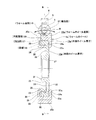
本参考例の場合には、ウォームホイール4bを構成する内側ホイール素子15bの軸方向他側面の構成が、上述した参考例の第1例の場合と異なる。即ち、本参考例の場合には、ウォームホイール4bを構成する内側ホイール素子15bの軸方向他側面にも、この内側ホイール素子15bの軸方向片側面に存在する環状凹部22及び凹凸部27と同様の構成を有する、環状凹部22b(外径側周面23b、底面24b、内径側周面25b)及び凹凸部27a(複数ずつの凹部28a、凸部29a)が設けられている。
In the case of this reference example, the configuration of the other side surface in the axial direction of the
そして、外側ホイール素子16bを構成する合成樹脂の一部を、前記環状凹部22bの径方向外端部に入り込ませて、この環状凹部22bに入り込んだ部分を円環状の抑え部34bとしている。これと共に、前記外側ホイール素子16bを構成する合成樹脂の一部を、前記凹凸部27aを構成する各凹部28aの全体に入り込ませて、前記凹凸部27aの表面全体を覆う事により、この凹凸部27aと係合する回転保持部36aとしている。そして、この様な構成を採用する事により、前記内側ホイール素子15bに対する前記外側ホイール素子16bの、モーメントM方向及び回転方向の保持力を高めている。
Then, a part of the synthetic resin constituting the
尚、本参考例の場合には、前記環状凹部22の内面に副凹部を設けていないが、本参考例を実施する場合も、この副凹部を前記環状凹部22(22b)の内面に設けると共に、この副凹部に前記合成樹脂の一部を入り込ませる事もできる。
その他の構成及び作用は、上述した参考例の第1例の場合と同様である。
In the case of this reference example, the sub-recess is not provided on the inner surface of the
Other configurations and operations are the same as in the case of the first example of the above-mentioned reference example .
[参考例の第3例]
本発明に関連する参考例の第3例に就いて、図7により説明する。
本参考例は、上述の図6に示した参考例の第2例の変形例である。
[Third example of reference example ]
A third example of a reference example related to the present invention will be described with reference to FIG.
This reference example is a modification of the second example of the reference example shown in FIG. 6 above.
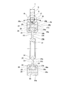
本参考例の場合には、ウォームホイール4cを構成する内側ホイール素子15cの軸方向両側面の径方向外端部に設けられた凹凸部27b、27cの構成が、上述した参考例の第2例の場合と異なる。即ち、本参考例の場合には、前記両凹凸部27b、27cを構成する各凹部28b、28cの軸方向深さ(各凸部29a、29bの軸方向高さ)を、径方向内側に向かうに従って小さくしている。これにより、前記各凹部28b、28cの軸方向深さ(前記各凸部29a、29bの軸方向高さ)を、径方向外端縁部では上述した参考例の第2例の場合と同じ大きさとする一方で、径方向内端縁部では上述した参考例の第2例の場合よりも小さく(図示の例ではゼロに)している。
In the case of this reference example, the configuration of the
そして、この様な構成を採用する事により、前記各凹部28b、28cの容積を小さくする事によって、前記両凹凸部27b、27cを塑性加工で成形する場合の成形荷重を低く抑えられる様にし、製造コストの低減を図っている。又、1対の環状凹部22、22bの内面を構成する外径側周面23、23bに対する前記各凹部28b、28cの径方向内端部の開口面積を、上述した参考例の第2例の場合よりも小さく(図示の例ではゼロに)する事により、前記両外径側周面23、23bと外側ホイール素子16cを構成する1対の抑え部34、34bとの係合面積を大きくする事で、前記内側ホイール素子15cに対する前記外側ホイール素子16cの、モーメントM方向の保持力を高めている。
その他の構成及び作用は、上述した参考例の第2例の場合と同様である。
By adopting such a configuration, the volumes of the
Other configurations and operations are the same as in the second example of the above-mentioned reference example .
[参考例の第4例]
本発明に関連する参考例の第4例に就いて、図8により説明する。
本参考例は、上述の図6に示した参考例の第2例の変形例である。
[Fourth example of reference example ]
A fourth example of a reference example related to the present invention will be described with reference to FIG.
This reference example is a modification of the second example of the reference example shown in FIG. 6 above.
本参考例の場合には、ウォームホイール4dを構成する外側ホイール素子16dの構成が、上述した参考例の第2例の場合と異なる。
即ち、本参考例の場合には、前記外側ホイール素子16dを構成する1対の抑え部34c、34dにより、内側ホイール素子15dに設けられた1対の環状凹部22、22bの内面を構成する外径側周面23、23bから、これらの内面を構成する内径側周面25、25bまでの連続した範囲(これらの内面全体)を覆っている。そして、この様な構成を採用する事により、前記内側ホイール素子15dに対する前記外側ホイール素子16dの、モーメントM方向の保持力を高めている。
その他の構成及び作用は、上述した参考例の第2例の場合と同様である。
In the case of this reference example, the configuration of the
That is, in the case of this reference example, the pair of holding
Other configurations and operations are the same as in the second example of the above-mentioned reference example .
[実施の形態の第1例]
本発明の実施の形態の第1例に就いて、図9により説明する。
本例は、上述の図6に示した参考例の第2例の変形例である。
[ First Example of Embodiment]
A first example of the embodiment of the present invention will be described with reference to FIG.
This example is a modification of the second example of the reference example shown in FIG. 6 above.
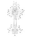
本例の場合には、ウォームホイール4eを構成する内側ホイール素子15eの径方向外端部(外径側環状部32a、円筒面部30a)の軸方向寸法を、上述した参考例の第2例の場合よりも大きくしている。これにより、ウォーム減速機を組み立てた状態で、前記内側ホイール素子15eの外周面に存在する円筒面部30aの軸方向に関する幅寸法Tが、ウォーム軸6の軸方向に関してウォーム歯部18とウォームホイール歯部19aとが重畳している領域38(噛合部37を含む領域であり、図9に於いて、上側の破線で表された直線と下側の実線で表された円弧曲線とにより囲まれた弓形の領域)の、前記ウォームホイール4eの軸方向に関する幅寸法U以上{T≧U(図3に示した例ではT>U)}になっていると共に、前記ウォームホイール4eの軸方向に関して、前記領域38の位置する範囲が、前記円筒面部30aの位置する範囲内に収まる様にしている。
In the case of this example, the axial dimensions of the radial outer end portion (outer diameter side
前記ウォーム減速機の使用に伴い、前記ウォーム歯部18と前記ウォームホイール歯部19aとの噛合部37で摩耗が生じると、この噛合部37の軸方向幅寸法Sが増大する。但し、この噛合部37は、前記領域38内に存在する部位である為、この噛合部37の軸方向幅寸法Sが増大したとしても、その最大値は、前記領域38の軸方向幅寸法Uにとどまり、この領域38の軸方向幅寸法Uを超える事はない。つまり、前記ウォームホイール4eの軸方向に関して、前記噛合部37が、前記領域38の外側にはみ出す事はない。従って、上述の様な構成を採用している本例の場合には、前記噛合部37で摩耗が生じる事により、この噛合部37の軸方向幅寸法Sが増大したとしても、この噛合部37の全体が前記円筒面部30aと径方向に重畳している状態を保持する事ができ、前記噛合部37の噛合状態を良好に保つ事ができる。
その他の構成及び作用は、上述した参考例の第2例の場合と同様である。
When the meshing
Other configurations and operations are the same as in the second example of the above-mentioned reference example .
尚、本発明を実施する場合には、上述した実施の形態及び各参考例の構成を適宜組み合わせて実施する事ができる。 In the case of implementing the present invention can be implemented in combination form of implementation described above and the configuration of each reference examples as appropriate.
又、上述した実施の形態及び各参考例では、内側ホイール素子を金属製としたが、本発明を実施する場合には、例えば内側ホイール素子を、外側ホイール素子を構成する合成樹脂よりも耐熱性の優れた合成樹脂製とする事もできる。この場合でも、上述した実施の形態及び各参考例の場合と同様の効果を得られる。 Further, in the embodiments and reference examples of implementation described above, but the inner wheel element is made of metal, when practicing the present invention, for example, the inner wheel element, than the synthetic resin forming the outer wheel element It can also be made of synthetic resin having excellent heat resistance. In this case, it is possible to obtain the same effects as the embodiments and reference examples of implementation described above.
又、上述した実施の形態及び各参考例の構造に於いて、内側ホイール素子の表面のうち、外側ホイール素子を構成する合成樹脂により覆われる部分のうちの少なくとも一部分(例えば前記円筒面部、前記内側ホイール素子の表面全体)を、ローレット加工、シボ加工、ショットブラストなどの各種の加工によって形成された、微細な凹凸面とすれば、この微細な凹凸面を構成する凹部に前記外側ホイール素子を構成する合成樹脂の一部が入り込む為、前記内側ホイール素子に対する前記外側ホイール素子の保持力(密着性)を高める事ができる。尚、この様な構成を採用する場合でも、前記微細な凹凸面を構成する凹部の深さを、前記ウォームホイール歯部を構成する歯の径方向高さの1/10以下(例えば1/20以下や1/30以下)として、前記外側ホイール素子を構成する合成樹脂の体積に余り影響を与えなければ、ウォームホイール歯部のうちウォーム歯部と噛合する部分の製造誤差を抑えられる。 Further, in the structure of the embodiment and the reference example of implementation described above, of the surface of the inner wheel elements, at least a portion (e.g., the cylindrical surface of the portion covered by the synthetic resin forming the outer wheel element, If the entire surface of the inner wheel element) is a fine concavo-convex surface formed by various processing such as lauret processing, grain processing, shot blasting, etc., the outer wheel element is formed in a recess constituting the fine concavo-convex surface. Since a part of the synthetic resin constituting the above is inserted, the holding force (adhesion) of the outer wheel element with respect to the inner wheel element can be increased. Even when such a configuration is adopted, the depth of the recesses constituting the fine uneven surface is 1/10 or less (for example, 1/20) of the radial height of the teeth constituting the worm wheel tooth portion. If the volume of the synthetic resin constituting the outer wheel element is not significantly affected, the manufacturing error of the portion of the worm wheel tooth portion that meshes with the worm tooth portion can be suppressed.
本発明のウォームホイール及びウォーム減速機は、電動式パワーステアリング装置に限らず、ワイパー装置等の各種の機械装置に組み込んで使用する事ができる。 The worm wheel and worm reducer of the present invention can be used by being incorporated in various mechanical devices such as a wiper device as well as an electric power steering device.
1 ステアリングホイール
2 ステアリングシャフト
3 ハウジング
4、4a〜4e ウォームホイール
5 電動モータ
6 ウォーム軸
7 出力軸
8a、8b 転がり軸受
9 トーションバー
10 トルクセンサ
11a、11b 自在継手
12 中間シャフト
13 ステアリングギヤユニット
14 ピニオン軸
15、15a〜15e 内側ホイール素子
16、16a〜16e 外側ホイール素子
17 凹凸部
18 ウォーム歯部
19、19a ウォームホイール歯部
20、20a 歯
21 嵌合孔
22、22a、22b 環状凹部
23、23a、23b 外径側周面
24、24a、24b 底面
25、25a、25b 内径側周面
26 副凹部
27、27a〜27c 凹凸部
28、28a〜28c 凹部
29、29a〜29c 凸部
30、30a 円筒面部
31 内径側環状部
32、32a 外径側環状部
33 連結部
34、34a〜34d 抑え部
35 副抑え部
36、36a 回転保持部
37 噛合部
38 領域
1
Claims (6)
外周面にウォーム歯部を有し、このウォーム歯部を前記ウォームホイール歯部に噛合させたウォーム軸と、
を備え、
前記ウォームホイールは、内側ホイール素子と、外側ホイール素子とを有するものであり、
前記内側ホイール素子は、円環状に構成され、軸方向側面のうちで外周縁よりも径方向内側に位置する部分に全周に亙り軸方向に凹む状態で設けられた環状凹部と、外周面と前記環状凹部との間に挟まれた部分に設けられた凹凸部とを有すると共に、外周面のうちで軸方向に関して前記凹凸部から外れた軸方向範囲の全体が円筒面部になっており、
前記外側ホイール素子は、合成樹脂製で円環状に構成され、外周面に前記ウォームホイール歯部を有し、前記内側ホイール素子の径方向外端部を全周に亙り包埋していると共に、前記合成樹脂の一部が前記環状凹部と前記凹凸部を構成する凹部とに入り込んでおり、
前記ウォームホイール歯部と前記ウォーム歯部との噛合部の全体が、前記ウォームホイールの径方向に関して前記円筒面部と重畳しており、
前記円筒面部の軸方向に関する幅寸法が、前記ウォーム軸の軸方向に関して前記ウォームホイール歯部と前記ウォーム歯部とが重畳している領域の、前記ウォームホイールの軸方向に関する幅寸法以上になっていると共に、前記ウォームホイールの軸方向に関して、前記領域の位置する範囲が前記円筒面部の位置する範囲内に収まっている
ウォーム減速機。 A worm wheel with worm wheel teeth on the outer peripheral surface,
A worm shaft having worm teeth on the outer peripheral surface and engaging the worm teeth with the worm wheel teeth,
With
The worm wheel has an inner wheel element and an outer wheel element.
The inner wheel element is formed of an annular shape, and has an annular recess formed in a portion of the axial side surface located radially inside the outer peripheral edge in a state of being recessed in the axial direction over the entire circumference, and an outer peripheral surface. It has an uneven portion provided in a portion sandwiched between the annular recess and the outer peripheral surface, and the entire axial range deviated from the concave-convex portion in the axial direction is a cylindrical surface portion.
The outer wheel element is made of synthetic resin and is formed in an annular shape, has the worm wheel tooth portion on the outer peripheral surface, and embeds the radial outer end portion of the inner wheel element all around. A part of the synthetic resin has entered the annular recess and the recess constituting the uneven portion.
The entire meshing portion between the worm wheel tooth portion and the worm tooth portion overlaps with the cylindrical surface portion in the radial direction of the worm wheel .
The width dimension of the cylindrical surface portion in the axial direction is equal to or greater than the width dimension in the axial direction of the worm wheel in the region where the worm wheel tooth portion and the worm tooth portion overlap with respect to the axial direction of the worm shaft. A worm reducer in which the range where the region is located is within the range where the cylindrical surface portion is located with respect to the axial direction of the worm wheel .
請求項1に記載したウォーム減速機。 The first aspect of claim 1, wherein the uneven portion is an uneven portion in the circumferential direction provided in a portion of the axial side surface of the inner wheel element sandwiched between the outer peripheral surface and the annular recess in the radial direction. Warm reducer.
請求項2に記載したウォーム減速機。 The worm reducer according to claim 2, wherein the axial depth of the concave portion constituting the uneven portion becomes smaller toward the inner side in the radial direction.
請求項1〜3のうちの何れか1項に記載したウォーム減速機。 The portion of the synthetic resin constituting the outer wheel element that has entered the annular recess covers a continuous range from the outer diameter side peripheral surface that constitutes the inner surface of the annular recess to the inner diameter side peripheral surface that constitutes this inner surface. The worm reducer according to any one of claims 1 to 3.
請求項1〜4のうちの何れか1項に記載したウォーム減速機。 The worm reducer according to any one of claims 1 to 4 , wherein the annular recess and the uneven portion are provided on both side surfaces in the axial direction of the inner wheel element.
請求項1〜5のうちの何れか1項に記載したウォーム減速機。 In any one of claims 1 to 5 , at least a part of the surface of the inner wheel element covered with the synthetic resin constituting the outer wheel element is a fine uneven surface. Worm reducer described.
Priority Applications (1)
| Application Number | Priority Date | Filing Date | Title |
|---|---|---|---|
| JP2016204198A JP6780434B2 (en) | 2016-10-18 | 2016-10-18 | Warm reducer |
Applications Claiming Priority (1)
| Application Number | Priority Date | Filing Date | Title |
|---|---|---|---|
| JP2016204198A JP6780434B2 (en) | 2016-10-18 | 2016-10-18 | Warm reducer |
Publications (3)
| Publication Number | Publication Date |
|---|---|
| JP2018066409A JP2018066409A (en) | 2018-04-26 |
| JP2018066409A5 JP2018066409A5 (en) | 2019-07-11 |
| JP6780434B2 true JP6780434B2 (en) | 2020-11-04 |
Family
ID=62086880
Family Applications (1)
| Application Number | Title | Priority Date | Filing Date |
|---|---|---|---|
| JP2016204198A Active JP6780434B2 (en) | 2016-10-18 | 2016-10-18 | Warm reducer |
Country Status (1)
| Country | Link |
|---|---|
| JP (1) | JP6780434B2 (en) |
Families Citing this family (1)
| Publication number | Priority date | Publication date | Assignee | Title |
|---|---|---|---|---|
| JP7464379B2 (en) * | 2019-11-26 | 2024-04-09 | 津田駒工業株式会社 | Rotational Drive Unit |
-
2016
- 2016-10-18 JP JP2016204198A patent/JP6780434B2/en active Active
Also Published As
| Publication number | Publication date |
|---|---|
| JP2018066409A (en) | 2018-04-26 |
Similar Documents
| Publication | Publication Date | Title |
|---|---|---|
| JP6547895B2 (en) | Worm wheel and worm reducer | |
| WO2017135141A1 (en) | Worm wheel, worm reduction gear, and method for producing worm wheel | |
| JP5429406B2 (en) | Worm wheel and electric power steering device | |
| JP5562532B2 (en) | Worm wheel of electric power steering device, electric power steering device | |
| JP6780434B2 (en) | Warm reducer | |
| JP2018204660A (en) | Worm wheel, worm reduction gear and manufacturing method of worm wheel | |
| CN206125141U (en) | Electrodynamic type power steering casing for device | |
| JP4997488B2 (en) | Compound gear and electric power steering device | |
| JP6547854B2 (en) | Worm wheel, worm reducer, and worm wheel manufacturing method | |
| JP6583437B2 (en) | Worm wheel and worm reducer | |
| KR102017079B1 (en) | Manufacturing method of worm wheel | |
| JP7318440B2 (en) | Worm wheel and manufacturing method thereof, worm reduction gear | |
| JP2017082859A (en) | Gear and steering device | |
| JP2022099886A (en) | Worm wheel, electric power steering device, and manufacturing method for worm wheel | |
| JP2014137114A (en) | Worm wheel | |
| JP2021042839A (en) | Worm wheel unit, its manufacturing method and worm reduction gear | |
| JP5016656B2 (en) | Worm gear | |
| JP2018203206A (en) | Steering device and worm wheel |
Legal Events
| Date | Code | Title | Description |
|---|---|---|---|
| A521 | Written amendment |
Free format text: JAPANESE INTERMEDIATE CODE: A523 Effective date: 20190605 |
|
| A621 | Written request for application examination |
Free format text: JAPANESE INTERMEDIATE CODE: A621 Effective date: 20190605 |
|
| A977 | Report on retrieval |
Free format text: JAPANESE INTERMEDIATE CODE: A971007 Effective date: 20200521 |
|
| A131 | Notification of reasons for refusal |
Free format text: JAPANESE INTERMEDIATE CODE: A131 Effective date: 20200623 |
|
| A521 | Written amendment |
Free format text: JAPANESE INTERMEDIATE CODE: A523 Effective date: 20200805 |
|
| TRDD | Decision of grant or rejection written | ||
| A01 | Written decision to grant a patent or to grant a registration (utility model) |
Free format text: JAPANESE INTERMEDIATE CODE: A01 Effective date: 20200915 |
|
| A61 | First payment of annual fees (during grant procedure) |
Free format text: JAPANESE INTERMEDIATE CODE: A61 Effective date: 20200928 |
|
| R150 | Certificate of patent or registration of utility model |
Ref document number: 6780434 Country of ref document: JP Free format text: JAPANESE INTERMEDIATE CODE: R150 |