JP6780024B2 - Turbo economizer used in chiller systems - Google Patents
Turbo economizer used in chiller systems Download PDFInfo
- Publication number
- JP6780024B2 JP6780024B2 JP2018560885A JP2018560885A JP6780024B2 JP 6780024 B2 JP6780024 B2 JP 6780024B2 JP 2018560885 A JP2018560885 A JP 2018560885A JP 2018560885 A JP2018560885 A JP 2018560885A JP 6780024 B2 JP6780024 B2 JP 6780024B2
- Authority
- JP
- Japan
- Prior art keywords
- refrigerant
- economizer
- turbo
- impeller
- turbine
- Prior art date
- Legal status (The legal status is an assumption and is not a legal conclusion. Google has not performed a legal analysis and makes no representation as to the accuracy of the status listed.)
- Active
Links
- 239000003507 refrigerant Substances 0.000 claims description 156
- 238000000034 method Methods 0.000 claims description 24
- 239000007788 liquid Substances 0.000 claims description 23
- 230000008569 process Effects 0.000 claims description 23
- 238000005057 refrigeration Methods 0.000 claims description 5
- 239000012528 membrane Substances 0.000 claims description 4
- 239000002826 coolant Substances 0.000 claims 2
- 239000007789 gas Substances 0.000 description 25
- 238000001816 cooling Methods 0.000 description 13
- 238000010586 diagram Methods 0.000 description 12
- 230000006870 function Effects 0.000 description 5
- XLYOFNOQVPJJNP-UHFFFAOYSA-N water Substances O XLYOFNOQVPJJNP-UHFFFAOYSA-N 0.000 description 3
- 230000009471 action Effects 0.000 description 2
- 230000008901 benefit Effects 0.000 description 2
- 230000008859 change Effects 0.000 description 2
- 238000007796 conventional method Methods 0.000 description 2
- 238000013461 design Methods 0.000 description 2
- 230000006872 improvement Effects 0.000 description 2
- 238000012986 modification Methods 0.000 description 2
- 230000004048 modification Effects 0.000 description 2
- 238000012546 transfer Methods 0.000 description 2
- 238000010792 warming Methods 0.000 description 2
- LVGUZGTVOIAKKC-UHFFFAOYSA-N 1,1,1,2-tetrafluoroethane Chemical compound FCC(F)(F)F LVGUZGTVOIAKKC-UHFFFAOYSA-N 0.000 description 1
- 239000006227 byproduct Substances 0.000 description 1
- 230000006835 compression Effects 0.000 description 1
- 238000007906 compression Methods 0.000 description 1
- 239000000498 cooling water Substances 0.000 description 1
- 238000001514 detection method Methods 0.000 description 1
- 230000008020 evaporation Effects 0.000 description 1
- 238000001704 evaporation Methods 0.000 description 1
- 239000010408 film Substances 0.000 description 1
- 239000012530 fluid Substances 0.000 description 1
- 238000007710 freezing Methods 0.000 description 1
- 230000008014 freezing Effects 0.000 description 1
- 238000010438 heat treatment Methods 0.000 description 1
- 230000002706 hydrostatic effect Effects 0.000 description 1
- 238000005259 measurement Methods 0.000 description 1
- 230000007246 mechanism Effects 0.000 description 1
- 239000003607 modifier Substances 0.000 description 1
- 231100000252 nontoxic Toxicity 0.000 description 1
- 230000003000 nontoxic effect Effects 0.000 description 1
- 230000003134 recirculating effect Effects 0.000 description 1
- 230000003068 static effect Effects 0.000 description 1
- 239000000126 substance Substances 0.000 description 1
- 239000010409 thin film Substances 0.000 description 1
- 239000002918 waste heat Substances 0.000 description 1
Images


Classifications
-
- F—MECHANICAL ENGINEERING; LIGHTING; HEATING; WEAPONS; BLASTING
- F25—REFRIGERATION OR COOLING; COMBINED HEATING AND REFRIGERATION SYSTEMS; HEAT PUMP SYSTEMS; MANUFACTURE OR STORAGE OF ICE; LIQUEFACTION SOLIDIFICATION OF GASES
- F25B—REFRIGERATION MACHINES, PLANTS OR SYSTEMS; COMBINED HEATING AND REFRIGERATION SYSTEMS; HEAT PUMP SYSTEMS
- F25B1/00—Compression machines, plants or systems with non-reversible cycle
- F25B1/10—Compression machines, plants or systems with non-reversible cycle with multi-stage compression
-
- F—MECHANICAL ENGINEERING; LIGHTING; HEATING; WEAPONS; BLASTING
- F01—MACHINES OR ENGINES IN GENERAL; ENGINE PLANTS IN GENERAL; STEAM ENGINES
- F01D—NON-POSITIVE DISPLACEMENT MACHINES OR ENGINES, e.g. STEAM TURBINES
- F01D5/00—Blades; Blade-carrying members; Heating, heat-insulating, cooling or antivibration means on the blades or the members
- F01D5/12—Blades
- F01D5/14—Form or construction
- F01D5/141—Shape, i.e. outer, aerodynamic form
-
- F—MECHANICAL ENGINEERING; LIGHTING; HEATING; WEAPONS; BLASTING
- F25—REFRIGERATION OR COOLING; COMBINED HEATING AND REFRIGERATION SYSTEMS; HEAT PUMP SYSTEMS; MANUFACTURE OR STORAGE OF ICE; LIQUEFACTION SOLIDIFICATION OF GASES
- F25B—REFRIGERATION MACHINES, PLANTS OR SYSTEMS; COMBINED HEATING AND REFRIGERATION SYSTEMS; HEAT PUMP SYSTEMS
- F25B11/00—Compression machines, plants or systems, using turbines, e.g. gas turbines
- F25B11/02—Compression machines, plants or systems, using turbines, e.g. gas turbines as expanders
- F25B11/04—Compression machines, plants or systems, using turbines, e.g. gas turbines as expanders centrifugal type
-
- F—MECHANICAL ENGINEERING; LIGHTING; HEATING; WEAPONS; BLASTING
- F25—REFRIGERATION OR COOLING; COMBINED HEATING AND REFRIGERATION SYSTEMS; HEAT PUMP SYSTEMS; MANUFACTURE OR STORAGE OF ICE; LIQUEFACTION SOLIDIFICATION OF GASES
- F25B—REFRIGERATION MACHINES, PLANTS OR SYSTEMS; COMBINED HEATING AND REFRIGERATION SYSTEMS; HEAT PUMP SYSTEMS
- F25B39/00—Evaporators; Condensers
-
- F—MECHANICAL ENGINEERING; LIGHTING; HEATING; WEAPONS; BLASTING
- F25—REFRIGERATION OR COOLING; COMBINED HEATING AND REFRIGERATION SYSTEMS; HEAT PUMP SYSTEMS; MANUFACTURE OR STORAGE OF ICE; LIQUEFACTION SOLIDIFICATION OF GASES
- F25B—REFRIGERATION MACHINES, PLANTS OR SYSTEMS; COMBINED HEATING AND REFRIGERATION SYSTEMS; HEAT PUMP SYSTEMS
- F25B41/00—Fluid-circulation arrangements
- F25B41/30—Expansion means; Dispositions thereof
- F25B41/39—Dispositions with two or more expansion means arranged in series, i.e. multi-stage expansion, on a refrigerant line leading to the same evaporator
-
- F—MECHANICAL ENGINEERING; LIGHTING; HEATING; WEAPONS; BLASTING
- F25—REFRIGERATION OR COOLING; COMBINED HEATING AND REFRIGERATION SYSTEMS; HEAT PUMP SYSTEMS; MANUFACTURE OR STORAGE OF ICE; LIQUEFACTION SOLIDIFICATION OF GASES
- F25B—REFRIGERATION MACHINES, PLANTS OR SYSTEMS; COMBINED HEATING AND REFRIGERATION SYSTEMS; HEAT PUMP SYSTEMS
- F25B43/00—Arrangements for separating or purifying gases or liquids; Arrangements for vaporising the residuum of liquid refrigerant, e.g. by heat
-
- F—MECHANICAL ENGINEERING; LIGHTING; HEATING; WEAPONS; BLASTING
- F25—REFRIGERATION OR COOLING; COMBINED HEATING AND REFRIGERATION SYSTEMS; HEAT PUMP SYSTEMS; MANUFACTURE OR STORAGE OF ICE; LIQUEFACTION SOLIDIFICATION OF GASES
- F25B—REFRIGERATION MACHINES, PLANTS OR SYSTEMS; COMBINED HEATING AND REFRIGERATION SYSTEMS; HEAT PUMP SYSTEMS
- F25B2339/00—Details of evaporators; Details of condensers
- F25B2339/02—Details of evaporators
- F25B2339/024—Evaporators with refrigerant in a vessel in which is situated a heat exchanger
- F25B2339/0242—Evaporators with refrigerant in a vessel in which is situated a heat exchanger having tubular elements
-
- F—MECHANICAL ENGINEERING; LIGHTING; HEATING; WEAPONS; BLASTING
- F25—REFRIGERATION OR COOLING; COMBINED HEATING AND REFRIGERATION SYSTEMS; HEAT PUMP SYSTEMS; MANUFACTURE OR STORAGE OF ICE; LIQUEFACTION SOLIDIFICATION OF GASES
- F25B—REFRIGERATION MACHINES, PLANTS OR SYSTEMS; COMBINED HEATING AND REFRIGERATION SYSTEMS; HEAT PUMP SYSTEMS
- F25B2400/00—General features or devices for refrigeration machines, plants or systems, combined heating and refrigeration systems or heat-pump systems, i.e. not limited to a particular subgroup of F25B
- F25B2400/07—Details of compressors or related parts
- F25B2400/075—Details of compressors or related parts with parallel compressors
- F25B2400/0751—Details of compressors or related parts with parallel compressors the compressors having different capacities
-
- F—MECHANICAL ENGINEERING; LIGHTING; HEATING; WEAPONS; BLASTING
- F25—REFRIGERATION OR COOLING; COMBINED HEATING AND REFRIGERATION SYSTEMS; HEAT PUMP SYSTEMS; MANUFACTURE OR STORAGE OF ICE; LIQUEFACTION SOLIDIFICATION OF GASES
- F25B—REFRIGERATION MACHINES, PLANTS OR SYSTEMS; COMBINED HEATING AND REFRIGERATION SYSTEMS; HEAT PUMP SYSTEMS
- F25B2400/00—General features or devices for refrigeration machines, plants or systems, combined heating and refrigeration systems or heat-pump systems, i.e. not limited to a particular subgroup of F25B
- F25B2400/13—Economisers
-
- F—MECHANICAL ENGINEERING; LIGHTING; HEATING; WEAPONS; BLASTING
- F25—REFRIGERATION OR COOLING; COMBINED HEATING AND REFRIGERATION SYSTEMS; HEAT PUMP SYSTEMS; MANUFACTURE OR STORAGE OF ICE; LIQUEFACTION SOLIDIFICATION OF GASES
- F25B—REFRIGERATION MACHINES, PLANTS OR SYSTEMS; COMBINED HEATING AND REFRIGERATION SYSTEMS; HEAT PUMP SYSTEMS
- F25B2400/00—General features or devices for refrigeration machines, plants or systems, combined heating and refrigeration systems or heat-pump systems, i.e. not limited to a particular subgroup of F25B
- F25B2400/14—Power generation using energy from the expansion of the refrigerant
- F25B2400/141—Power generation using energy from the expansion of the refrigerant the extracted power is not recycled back in the refrigerant circuit
-
- F—MECHANICAL ENGINEERING; LIGHTING; HEATING; WEAPONS; BLASTING
- F25—REFRIGERATION OR COOLING; COMBINED HEATING AND REFRIGERATION SYSTEMS; HEAT PUMP SYSTEMS; MANUFACTURE OR STORAGE OF ICE; LIQUEFACTION SOLIDIFICATION OF GASES
- F25B—REFRIGERATION MACHINES, PLANTS OR SYSTEMS; COMBINED HEATING AND REFRIGERATION SYSTEMS; HEAT PUMP SYSTEMS
- F25B2400/00—General features or devices for refrigeration machines, plants or systems, combined heating and refrigeration systems or heat-pump systems, i.e. not limited to a particular subgroup of F25B
- F25B2400/23—Separators
-
- F—MECHANICAL ENGINEERING; LIGHTING; HEATING; WEAPONS; BLASTING
- F25—REFRIGERATION OR COOLING; COMBINED HEATING AND REFRIGERATION SYSTEMS; HEAT PUMP SYSTEMS; MANUFACTURE OR STORAGE OF ICE; LIQUEFACTION SOLIDIFICATION OF GASES
- F25B—REFRIGERATION MACHINES, PLANTS OR SYSTEMS; COMBINED HEATING AND REFRIGERATION SYSTEMS; HEAT PUMP SYSTEMS
- F25B27/00—Machines, plants or systems, using particular sources of energy
-
- F—MECHANICAL ENGINEERING; LIGHTING; HEATING; WEAPONS; BLASTING
- F25—REFRIGERATION OR COOLING; COMBINED HEATING AND REFRIGERATION SYSTEMS; HEAT PUMP SYSTEMS; MANUFACTURE OR STORAGE OF ICE; LIQUEFACTION SOLIDIFICATION OF GASES
- F25B—REFRIGERATION MACHINES, PLANTS OR SYSTEMS; COMBINED HEATING AND REFRIGERATION SYSTEMS; HEAT PUMP SYSTEMS
- F25B39/00—Evaporators; Condensers
- F25B39/02—Evaporators
Landscapes
- Engineering & Computer Science (AREA)
- Physics & Mathematics (AREA)
- Mechanical Engineering (AREA)
- General Engineering & Computer Science (AREA)
- Thermal Sciences (AREA)
- Chemical & Material Sciences (AREA)
- Analytical Chemistry (AREA)
- Power Engineering (AREA)
- Fluid Mechanics (AREA)
- Structures Of Non-Positive Displacement Pumps (AREA)
- Organic Low-Molecular-Weight Compounds And Preparation Thereof (AREA)
Description
本発明は、概して、チラーシステム用のターボエコノマイザに関する。 The present invention generally relates to turbo economizers for chiller systems.
チラーシステムは、媒体から熱を取り除く冷凍機械又は装置である。通常、水等の液体が媒体として使用され、チラーシステムは、蒸気圧縮冷凍サイクルにおいて動作する。そして、この液体は、熱交換器を循環することによって、空気又は機器を必要に応じて冷却することができる。必須の副生成物として冷媒による廃熱が生成されるため、これを周囲に排気するか、効率を高めるために回収して加熱に用いるかが必要となる。従来のチラーシステムは、多くの場合、ターボ圧縮機としばしば呼ばれる遠心圧縮機を利用する。従って、これらのチラーシステムをターボチラーと呼ぶことができる。或いは、例えばスクリュー圧縮機等のその他の種類の圧縮機を利用することもできる。 A chiller system is a refrigeration machine or device that removes heat from a medium. Liquids such as water are typically used as the medium and the chiller system operates in a steam compression refrigeration cycle. The liquid can then circulate in the heat exchanger to cool the air or equipment as needed. Since waste heat from the refrigerant is generated as an essential by-product, it is necessary to exhaust it to the surroundings or recover it and use it for heating in order to improve efficiency. Traditional chiller systems often utilize centrifugal compressors, often referred to as turbo compressors. Therefore, these chiller systems can be called turbo chillers. Alternatively, other types of compressors, such as screw compressors, can be used.
従来の(ターボ)チラーでは、冷媒が遠心圧縮機において圧縮され、熱交換器に送られると、熱交換器において冷媒と熱交換媒体(液体)との間で熱交換がおこる。この熱交換器において冷媒が凝縮するため、この熱交換器は凝縮器と呼ばれる。結果として、熱が媒体(液体)に移るため、媒体が加熱される。凝縮器を出た冷媒は、膨張弁によって膨張させられてから別の熱交換器に送られ、この冷媒と熱交換媒体(液体)との間で熱交換がおこる。この熱交換器において冷媒が加熱(蒸発)するため、この熱交換器は蒸発器と呼ばれる。結果として、熱が媒体(液体)から冷媒に伝達され、液体が冷却される。そして、蒸発器からの冷媒は遠心圧縮機に戻され、このサイクルが繰り返される。多くの場合、利用される液体は、水である。 In a conventional (turbo) chiller, when the refrigerant is compressed in a centrifugal compressor and sent to a heat exchanger, heat exchange occurs between the refrigerant and the heat exchange medium (liquid) in the heat exchanger. This heat exchanger is called a condenser because the refrigerant condenses in this heat exchanger. As a result, heat is transferred to the medium (liquid), which heats the medium. The refrigerant discharged from the condenser is expanded by the expansion valve and then sent to another heat exchanger, and heat exchange occurs between this refrigerant and the heat exchange medium (liquid). This heat exchanger is called an evaporator because the refrigerant heats (evaporates) in this heat exchanger. As a result, heat is transferred from the medium (liquid) to the refrigerant to cool the liquid. Then, the refrigerant from the evaporator is returned to the centrifugal compressor, and this cycle is repeated. Often the liquid used is water.
従来の遠心圧縮機は基本的に、ケーシングと、インレットガイドベーンと、インペラと、ディフューザと、モータと、各種センサと、コントローラとを備える。冷媒は、インレットガイドベーン、インペラ、及びディフューザを順に流れる。従って、インレットガイドベーンは、遠心圧縮機のガス吸気ポートに連結され、ディフューザは、インペラのガス出口ポートに連結される。インレットガイドベーンは、インペラに入る冷媒ガスの流量を制御する。インペラは、冷媒ガスの速度を上げる。ディフューザは、インペラによって与えられる冷媒ガスの速度(動的な圧力)を(静的な)圧力に変換する働きをする。モータは、インペラを回転させる。コントローラは、モータ、インレットガイドベーン、及び膨張弁を制御する。従来の遠心圧縮機では、このようにして冷媒が圧縮される。 A conventional centrifugal compressor basically includes a casing, an inlet guide vane, an impeller, a diffuser, a motor, various sensors, and a controller. The refrigerant flows through the inlet guide vane, the impeller, and the diffuser in this order. Therefore, the inlet guide vane is connected to the gas intake port of the centrifugal compressor, and the diffuser is connected to the gas outlet port of the impeller. The inlet guide vane controls the flow rate of the refrigerant gas entering the impeller. The impeller increases the speed of the refrigerant gas. The diffuser serves to convert the velocity (dynamic pressure) of the refrigerant gas given by the impeller into (static) pressure. The motor rotates the impeller. The controller controls the motor, inlet guide vanes, and expansion valve. In a conventional centrifugal compressor, the refrigerant is compressed in this way.
チラーシステムの効率を高めるため、エコノマイザが使用されている。例えば、米国特許出願公開第2008/0098754号を参照されたい。エコノマイザが二相(気液)冷媒から冷媒ガスを分離すると、その冷媒ガスは、圧縮機の中間圧部に導かれる。 Economizers are used to increase the efficiency of the chiller system. See, for example, US Patent Application Publication No. 2008/0987754. When the economizer separates the refrigerant gas from the two-phase (gas-liquid) refrigerant, the refrigerant gas is guided to the intermediate pressure portion of the compressor.
従来のエコノマイザでは、エコノマイザから出る冷媒ガスの圧力が中間圧まで下げられ、その冷媒ガスが圧縮機の中間部に導かれる。圧縮機の中間圧を低下させると、チラーシステムの冷却能力を高めることができる。1つの従来技法によれば、圧縮機が異なるサイズの2つのインペラを備え、第1段のインペラを小さなサイズに第2段のインペラを大きなサイズにすることにより、圧縮機内の冷媒の低い中間圧を実現させることができる。この技法は比較的良好に機能するが、このシステムは、インペラにサイズ差を設けるために大型の圧縮機が必要であるため、コストが増大する。 In the conventional economizer, the pressure of the refrigerant gas emitted from the economizer is lowered to the intermediate pressure, and the refrigerant gas is guided to the intermediate portion of the compressor. Reducing the intermediate pressure of the compressor can increase the cooling capacity of the chiller system. According to one conventional technique, the compressor has two impellers of different sizes, the first stage impeller is smaller and the second stage impeller is larger, so that the lower intermediate pressure of the refrigerant in the compressor. Can be realized. While this technique works relatively well, the system is costly because it requires a large compressor to provide size differences in the impellers.
従って、本発明の1つの目的は、圧縮機内で異なるサイズのインペラを用いることなくチラーシステムの冷却能力の改良を実現するターボエコノマイザを提供することである。 Therefore, one object of the present invention is to provide a turbo economizer that realizes an improvement in the cooling capacity of a chiller system without using impellers of different sizes in the compressor.
本発明の別の目的は、別個のモータを使用することのない、自己動力式のターボエコノマイザを提供することである。 Another object of the present invention is to provide a self-powered turbo economizer that does not use a separate motor.
本発明の更に別の目的は、膨張機を使用することによって冷却能力を更に改良するターボエコノマイザを提供することである。 Yet another object of the present invention is to provide a turbo economizer that further improves the cooling capacity by using an expander.
本発明の更に別の目的は、本発明に係るターボエコノマイザを使用するチラーシステムを提供することである。 Yet another object of the present invention is to provide a chiller system using the turbo economizer according to the present invention.
上記の目的の1つ又は複数は、基本的には、冷凍回路を形成するように接続された圧縮機、蒸発器、及び凝縮器を含むチラーシステムにおいて使用されるように適合されたターボエコノマイザであって、ターボエコノマイザに冷媒を導くように構成及び配置されたノズルと、ノズルの下流に配置されたタービンであって、回転軸周りで回転可能なシャフトに取り付けられ、ノズルを通して導かれる冷媒の流れによって駆動されてシャフトを回転させるタービンと、シャフトの回転に従って回転させられるようにシャフトに取り付けられたエコノマイザインペラと、を含むターボエコノマイザを提供することによって達成することができる。ターボエコノマイザにおいて、ノズルは、ターボエコノマイザに入る冷媒の圧力が所定の圧力よりも低くなるように冷媒を減圧するよう更に構成及び配置されており、ノズルを通過する冷媒の少なくとも一部は、エコノマイザインペラに導かれ、エコノマイザインペラは、そこに導かれる冷媒を所定の圧力まで昇圧するように構成及び配置されている。 One or more of the above objectives is basically a turbo economizer adapted for use in chiller systems including compressors, evaporators, and condensers connected to form a refrigeration circuit. There is a nozzle configured and arranged to guide the refrigerant to the turbo economizer, and a turbine located downstream of the nozzle, which is attached to a shaft that is rotatable around the axis of rotation and is guided through the nozzle. This can be achieved by providing a turbo economizer that includes a turbine driven by the shaft to rotate the shaft and an economizer impeller attached to the shaft so that it is rotated according to the rotation of the shaft. In the turbo economizer, the nozzle is further configured and arranged to depressurize the refrigerant so that the pressure of the refrigerant entering the turbo economizer is lower than a predetermined pressure, and at least a part of the refrigerant passing through the nozzle is an economizer impeller. The economizer impeller is configured and arranged to boost the refrigerant guided there to a predetermined pressure.
本発明の上記及びその他の目的、特徴、態様、及び利点は、以下の詳細な記載から当業者に明らかとなろう。以下の記載では、添付の図面と合わせて好適な実施形態を開示する。 The above and other objects, features, aspects, and advantages of the present invention will be apparent to those skilled in the art from the detailed description below. The following description discloses suitable embodiments in conjunction with the accompanying drawings.
ここで、本出願の元の開示の一部を成す添付図面を参照する。 See here the accompanying drawings that form part of the original disclosure of this application.
ここで、選択した実施形態を、図面を参照しながら説明する。以下の実施形態の説明は単なる例示であり、添付の請求項及びそれらの等価物で定義される本発明を限定するためのものではないことは、本開示から当業者に明らかであろう。 Here, the selected embodiment will be described with reference to the drawings. It will be apparent to those skilled in the art from the present disclosure that the description of the embodiments below is merely exemplary and is not intended to limit the invention as defined by the appended claims and their equivalents.
まず図1を参照すると、本発明の第1の実施形態に係るターボエコノマイザ26を含むチラーシステム10が示されている。チラーシステム10は、好ましくは、従来の方式で冷却水及びチラー水を利用する水冷チラーである。本明細書に示すチラーシステム10は、2段チラーシステムである。しかし、チラーシステム10が、中間段を有していれば更に多くの段を含む多段チラーシステムでもよいことは、本開示から当業者には明らかであろう。
First, referring to FIG. 1, a
チラーシステム10は、基本的には、圧縮機22、凝縮器24、膨張ノズル25、ターボエコノマイザ26、膨張弁27、及び蒸発器28を含み、それらは直列に接続されて、冷凍回路を形成している。更に、チラーシステム10の回路全体にわたって様々なセンサ(図示せず)が配置されている。
The
図1及び図2を参照すると、圧縮機22は、例示実施形態では2段遠心圧縮機である。より具体的には、本明細書に示す圧縮機22は、2つのインペラを含む2段遠心圧縮機である。しかし、圧縮機22は、より多くのインペラを含む多段遠心圧縮機でもよい。例示実施形態の2段遠心圧縮機22は、第1段インペラ34a及び第2段インペラ34bを含む。遠心圧縮機22は、第1段インレットガイドベーン32a、第1のディフューザ/ボリュート36a、第2段インレットガイドベーン32b、第2のディフューザ/ボリュート36b、圧縮機モータ38、及び磁気軸受アセンブリ40、並びに様々な従来のセンサ(図示せず)を更に含む。
With reference to FIGS. 1 and 2, the compressor 22 is a two-stage centrifugal compressor in the exemplary embodiment. More specifically, the compressor 22 shown herein is a two-stage centrifugal compressor containing two impellers. However, the compressor 22 may be a multi-stage centrifugal compressor containing more impellers. The two-stage centrifugal compressor 22 of the exemplary embodiment includes a first-stage impeller 34a and a second-
冷媒は、第1段インレットガイドベーン32a、第1段インペラ34a、第2段インレットガイドベーン32b、及び第2段インペラ34bを順に通って流れる。インレットガイドベーン32a、32bは、従来の方法でそれぞれインペラ34a、34b内への冷媒ガスの流量を制御する。インペラ34a、34bは、ほぼ圧力を変えることなく、冷媒ガスの速度を増加させる。モータ速度は、冷媒ガスの速度の増加量を決定する。ディフューザ/ボリュート36a、36bは、冷媒圧力を上昇させる。ディフューザ/ボリュート36a、36bは、圧縮機ケーシング30に対して移動不能に固定されている。圧縮機モータ38は、シャフト42を介してインペラ34a、34bを回転させる。磁気軸受アセンブリ40は、シャフト42を磁気的に支持する。磁気軸受アセンブリ40は、好ましくは、第1のラジアル磁気軸受44、第2のラジアル磁気軸受46、及びアキシャル(スラスト)磁気軸受48を含む。いずれの場合も、少なくとも1つのラジアル磁気軸受44又は46がシャフト42を回転可能に支持する。スラスト磁気軸受48は、回転軸に沿ってシャフト42を支持する。或いは、軸受システムは、ローラ要素、流体軸受、静圧軸受、及び/又は磁気軸受、又はこれらの任意の組合せを含んでいてもよい。このようにして、冷媒は遠心圧縮機22内で圧縮される。
The refrigerant flows through the first stage inlet guide vane 32a, the first stage impeller 34a, the second stage inlet guide vane 32b, and the
チラーシステム10の動作時、圧縮機22の第1段インペラ34a及び第2段インペラ34bが回転させられ、チラーシステム10内の低圧の冷媒が第1段インペラ34aに吸引される。冷媒の流量は、インレットガイドベーン32aによって調整される。第1段インペラ34aによって吸引された冷媒は圧縮されて中間圧にされ、第1のディフューザ/ボリュート36aによって冷媒圧力が上昇され、次いで冷媒は第2段インペラ34bに導かれる。冷媒の流量は、インレットガイドベーン32bによって調整される。第2段インペラ34bが中間圧の冷媒を圧縮して高圧にすると、その冷媒圧力は第2のディフューザ/ボリュート36bによって上昇させられる。次いで、高圧ガス冷媒はチラーシステム10に放出される。
During operation of the
上述したように、チラーシステム10は、本発明に係るターボエコノマイザ26を有する。チラーシステム10は、本発明に係るターボエコノマイザ26を除き従来のものである。従って、チラーシステム10は、ターボエコノマイザ26に関連する場合を除き、本明細書で更に詳細には説明及び/又は図示しない。しかし、本発明の範囲を逸脱することなく、チラーシステム10の従来の部品を様々な様式で構成することができることは、当業者には明らかであろう。
As described above, the
以下でより詳細に説明するように、ターボエコノマイザ26は、圧縮機22の中間段に接続されて、ガス冷媒を圧縮機22の中間段に注入する。例示実施形態では、ターボエコノマイザ26は、チラーシステム10内で蒸発器28と凝縮器24との間に配置されている。
As will be described in more detail below, the
図3A及び図6を参照すると、ターボエコノマイザ26は、基本的には、ノズル62、ペルトンホイールタービン64、及びエコノマイザインペラ66を含む。ペルトンホイールタービン64は、タービンケーシング65の内部に配置されている。エコノマイザインペラ66は、インペラケーシング67の内部に配置されている。ターボエコノマイザ26は、タービンケーシング65とインペラケーシング67とを接続する管状ケーシング(図示せず)を更に含む。管状ケーシングの一端はタービンケーシング65に取り付けられ、管状ケーシングの他端はインペラケーシング67に取り付けられている。
With reference to FIGS. 3A and 6, the
図3A、図5、図6、及び図7を参照すると、ターボエコノマイザ26は、シャフト70、軸受72、及び軸受ハウジング74を更に含む。シャフト70は、シャフト70の長手方向に沿って延びる回転軸周りで回転可能である。軸受72は、軸受ハウジング74の内部に配置されている。軸受72は固定され、シャフト70を回転可能に支持する。軸受72は従来のものであり、従って、本発明に関連する場合を除き、本明細書で詳細には説明及び/又は図示しない。本発明から逸脱することなく、任意の適切な軸受を使用することができることが当業者には明らかであろう。軸受72の例としては、例えば、ころ軸受、すべり軸受、及び/又は磁気軸受が挙げられる。図7に示す軸受72は、すべり軸受である。
With reference to FIGS. 3A, 5, 6, and 7, the
ノズル62は、ターボエコノマイザ26の入口に配置されて、凝縮器24から出た冷媒をターボエコノマイザ26に導く。ペルトンホイールタービン64は、ノズル62の下流に配置されている。ペルトンホイールタービン64は、シャフト70の一端に取り付けられている。エコノマイザインペラ66は、シャフト70の他端に取り付けられている。チラーシステム10内の冷媒の流れは、ノズル62からターボエコノマイザ26に入り、ペルトンホイールタービン64に進む。次いで、冷媒の流れが、ペルトンホイールタービン64を駆動させ、ペルトンホイールタービン64に取り付けられているシャフト70を回転させる。次いで、シャフト70の回転に応じてエコノマイザインペラ66が回転される。すなわち、ターボエコノマイザ26において、冷媒の流れを使用してペルトンホイールタービン64が発生した原動力がシャフト70を介して伝達され、伝達された原動力が、エコノマイザインペラ66を駆動させる。これにより、ターボエコノマイザ26は、別個のモータを使用しない冷媒動力式である。より具体的には、本発明に係るターボエコノマイザ26は、ペルトンホイールタービン64又はエコノマイザインペラ66を駆動させるための電動機等のモータを必要としない。
The
冷媒が通過する間、ノズル62は、冷媒の圧力を低下させ、冷媒の流速を増加させる。より具体的には、ノズル26により、ターボエコノマイザ26に流入する冷媒は、圧縮機22の中間段の冷媒の中間圧を下回るように減圧される。圧縮機22の中間段は、圧縮機22の第1段と第2段との間に位置する。ノズル62を通過する冷媒は、二相(気液)冷媒である。次いで、冷媒は、ペルトンホイールタービン64に導かれる。ペルトンホイールタービン64は、二相冷媒をガス冷媒と液冷媒とに分離する。ペルトンホイールタービン64も、冷媒の流速を低下させる。
While the refrigerant passes, the
ペルトンホイールタービン64において分離された液冷媒は、チラーシステム10内の膨張弁27に導かれる。他方、ペルトンホイールタービン64において分離された、主としてガス冷媒および微量の液冷媒を含む冷媒は、ペルトンホイールタービン64とエコノマイザインペラ66とを接続するパイプ(図示せず)を通してエコノマイザインペラ66に導かれる。エコノマイザインペラ66は、そこに導かれた冷媒の圧力を上昇させて中間圧にする。上述したように、エコノマイザインペラ66は、ペルトンホイールタービン64からの原動力によって駆動される。
The liquid refrigerant separated in the
エコノマイザインペラ66から出た冷媒は、圧縮機22の中間段に注入される。次いで、圧縮機22の中間段に注入されたガス冷媒は、圧縮機22の第1段インペラ34aによって圧縮された中間圧の冷媒と混合される。混合された冷媒は、第2段インペラ34bに流れて、更に圧縮される。
The refrigerant discharged from the
ここで、図3A、図3B、及び図5を参照して、ターボエコノマイザ26内での冷媒の流れ、及びターボエコノマイザ26の各位置での冷媒の圧力について説明する。凝縮器24から出た冷媒は、ノズル62を通ってターボエコノマイザ26に入る(位置A)。冷媒は、ノズル62によって中間圧よりも低くなるように減圧される。図3A及び図3Bにおけるプロセス(1)を参照されたい。ノズル62を通過した冷媒の流れは、ペルトンホイールタービン64に導かれる(位置B)。冷媒は、ペルトンホイールタービン64においてガス冷媒と液冷媒とに分離される。ペルトンホイールタービン64において分離された液冷媒は、ペルトンホイールタービン64から出て(位置D)、チラーシステム10内の膨張弁27に流れる。図3A及び図3Bにおけるプロセス(2)を参照されたい。他方、ペルトンホイールタービン64において分離されたガス冷媒は、ペルトンホイールタービン64から出て(位置C)、エコノマイザインペラ66に流れる(位置C’)。エコノマイザインペラ66によって、ガス冷媒は中間圧まで昇圧される。中間圧のガス冷媒は、エコノマイザインペラ66(位置E)から出て、圧縮機22の中間段に注入される。図3A及び図3Bにおけるプロセス(3)及び(4)を参照されたい。
Here, with reference to FIGS. 3A, 3B, and 5, the flow of the refrigerant in the
このようにして、ターボエコノマイザ26内の冷媒は、ノズル62により圧縮機22の中間圧よりもよりも低くなるように減圧される。また、冷媒を膨張させるプロセス(1)(位置Aから位置Bまで)から仕事(work)が抽出され、抽出された仕事がエコノマイザインペラ66に与えられる。本発明によれば、図3Bのp−h図に示すように、Δhが増加される。その結果、チラーシステム10の冷却能力の改良を実現することができる。
In this way, the refrigerant in the
図4A及び図4Bを参照して、冷却能力改良の工学値の一例を説明する。図4Aは、典型的なサイクルのp−h図であり、図4Bは、本発明に係るターボエコノマイザ26を使用した、改良されたサイクルのp−h図である。ここで説明する工学値は、冷媒としてR134aを使用する単なる例にすぎない。設計データ及び図は、冷媒の種類及び動作条件に応じて異なることが当業者には明らかであろう。これらの例では、図4Aに示すように、典型的なサイクルに関する中間圧は612kPaであり、図4Bに示すように、本発明に係る改良されたサイクルに関する中間圧は490kPaである。従って、中間圧は122kPa低減される。典型的なサイクルに関する冷却能力(蒸発器でのエンタルピー差)は172kJ/kgであり、本発明に係る改良されたサイクルに関する冷却能力は182kJ/kgである。従って、冷却能力は10kJ/kg増加される。典型的なサイクルに関する理論COP(成績係数)は8.21であり、本発明に係る改良されたサイクルに関する理論COPは8.69である。従って、理論COPは約5%増加される。このようにして、本発明に係るターボエコノマイザ26を使用することによって、COPが改良される。
<第2の実施形態>
An example of engineering values for improving cooling capacity will be described with reference to FIGS. 4A and 4B. FIG. 4A is a typical cycle p-h diagram, and FIG. 4B is an improved cycle p-h diagram using the
<Second embodiment>
図8Aを参照して、本発明の第2の実施形態に係るターボエコノマイザ26’について説明する。この実施形態では、ターボエコノマイザ26’は、膨張機68を更に含む。第2の実施形態に係るターボエコノマイザ26’の他の要素は、第1の実施形態に係るターボエコノマイザ26の要素と実質的に同一である。従って、第2の実施形態を理解するために必要な場合を除き、それらの要素についてはここでは詳細には論じない。第1の実施形態の説明及び図示は、ここで説明及び/又は図示する点を除き第2の実施形態にも当てはまる。
The turbo economizer 26'according to the second embodiment of the present invention will be described with reference to FIG. 8A. In this embodiment, the turbo economizer 26' further includes an expander 68. The other elements of the turbo economizer 26'according to the second embodiment are substantially the same as the elements of the
上述したように、第2の実施形態に係るターボエコノマイザ26’は、膨張機68を含む。膨張機68は、ペルトンホイールタービン64の下流に配置されている。膨張機68は、少なくとも1つの膨張機インペラを含む。膨張機68は、ペルトンホイールタービン64から膨張機68に導かれた冷媒に対して膨張プロセスを行う。膨張機68において膨張プロセスを経た冷媒は、チラーシステム10内の蒸発器28に導かれる。第2の実施形態に係るターボエコノマイザ26’を使用するチラーシステム10は、膨張弁27を必要としない。
As described above, the turbo economizer 26'according to the second embodiment includes an expander 68. The expander 68 is located downstream of the
ここで、図8A、図8B、及び図11を参照して、ターボエコノマイザ26’内の冷媒の流れ、及びターボエコノマイザ26’の各位置での冷媒の圧力について説明する。凝縮器24から出た冷媒は、ノズル62を通ってターボエコノマイザ26に入る(位置A)。この冷媒は、ノズル62によって中間圧よりも低くなるように減圧される。図8A及び図8Bにおけるプロセス(1)を参照されたい。ノズル62を通過した冷媒の流れは、ペルトンホイールタービン64に導かれる(位置B)。冷媒は、ペルトンホイールタービン64においてガス冷媒と液冷媒とに分離される。ペルトンホイールタービン64において分離されたガス冷媒は、ペルトンホイールタービン64から出て(位置C)、エコノマイザインペラ66に流れる(位置C’)。エコノマイザインペラ66によって、ガス冷媒の圧力は中間圧まで昇圧される。中間圧のガス冷媒は、エコノマイザインペラ66(位置E)から出て、圧縮機22の中間段に注入される。図8A及び図8Bにおけるプロセス(3)及び(4)を参照されたい。他方、ペルトンホイールタービン64において分離された液冷媒は、ペルトンホイールタービン64から出て(位置D)、後述する膨張機68A及び膨張機68Bを含む膨張機68に流れる。冷媒は、膨張機68において膨張プロセスを経る。膨張機68から出た冷媒(位置F)は、チラーシステム10内の蒸発器28に導かれる。図8A及び図8Bにおけるプロセス(2)を参照されたい。
Here, with reference to FIGS. 8A, 8B, and 11, the flow of the refrigerant in the turbo economizer 26'and the pressure of the refrigerant at each position of the turbo economizer 26'will be described. The refrigerant discharged from the
このようにして、ターボエコノマイザ26’内の冷媒は、圧縮機22の中間圧よりも低くなるように減圧される。また、冷媒を膨張させるプロセス(1)(位置Aから位置Bまで)から仕事が抽出され、抽出された仕事がエコノマイザインペラ66に与えられる。第2の実施形態に係るターボエコノマイザ26’では、膨張機68における膨張プロセス(位置Dから位置Fまで)から追加の仕事が抽出される。その結果、図8Bに示すように、チラーシステム10の冷却能力の更なる改良を実現することができる。
In this way, the refrigerant in the turbo economizer 26'is depressurized so as to be lower than the intermediate pressure of the compressor 22. In addition, work is extracted from the process (1) (position A to position B) of expanding the refrigerant, and the extracted work is given to the
図9A及び図9Bを参照して、冷却能力改良の工学値の一例を説明する。図9Aは、典型的なサイクルのp−h図であり、図9Bは、本発明の第2の実施形態に係るターボエコノマイザ26’を使用した、改良されたサイクルのp−h図である。ここで説明する工学値は、冷媒としてR134aを使用する単なる例にすぎない。設計データ及び図は、冷媒の種類及び動作条件に応じて異なることが当業者には明らかであろう。これらの例では、図9Aに示すように、典型的なサイクルに関する中間圧は612kPaであり、図9Bに示すように、本発明の第2の実施形態に係る改良されたサイクルに関する中間圧は490kPaである。従って、中間圧は122kPa低減される。典型的なサイクルに関する冷却能力(蒸発器でのエンタルピー差)は172kJ/kgであり、本発明の第2の実施形態に係る改良されたサイクルに関する冷却能力は201kJ/kgである。従って、冷却能力は29kJ/kg増加される。典型的なサイクルに関する理論COP(成績係数)は8.21であり、本発明の第2の実施形態に係る改良されたサイクルに関する理論COPは9.60である。従って、理論COPは約17%増加される。このようにして、本発明の第2の実施形態に係るターボエコノマイザ26’を使用することによって、COPが更に改良される。 An example of engineering values for improving cooling capacity will be described with reference to FIGS. 9A and 9B. FIG. 9A is a typical cycle ph diagram, and FIG. 9B is an improved cycle ph diagram using the turbo economizer 26'according to a second embodiment of the present invention. The engineering values described here are merely examples of using R134a as the refrigerant. It will be apparent to those skilled in the art that the design data and figures will vary depending on the type of refrigerant and operating conditions. In these examples, as shown in FIG. 9A, the intermediate pressure for a typical cycle is 612 kPa, and as shown in FIG. 9B, the intermediate pressure for an improved cycle according to a second embodiment of the invention is 490 kPa. Is. Therefore, the intermediate pressure is reduced by 122 kPa. The cooling capacity for a typical cycle (enthalpy difference in the evaporator) is 172 kJ / kg, and the cooling capacity for the improved cycle according to the second embodiment of the present invention is 201 kJ / kg. Therefore, the cooling capacity is increased by 29 kJ / kg. The theoretical COP (coefficient of performance) for a typical cycle is 8.21, and the theoretical COP for an improved cycle according to a second embodiment of the present invention is 9.60. Therefore, the theoretical COP is increased by about 17%. In this way, the COP is further improved by using the turbo economizer 26'according to the second embodiment of the present invention.
図10A及び図10Bに示すように、本発明の第2の実施形態に係るターボエコノマイザ26’の膨張機68は、発電機又はポンプとして使用することができる。膨張機68Aを発電機(図10A)として使用する場合、膨張機68Aでの回転エネルギーが、発電機において電気エネルギーを得るために利用される。膨張機68Bをポンプとして使用する場合(図10B)、膨張機68Bは、以下により詳細に説明するように、流下膜式蒸発器を通して冷媒を再循環させるためのポンプとして機能する。
As shown in FIGS. 10A and 10B, the expander 68 of the turbo economizer 26'according to the second embodiment of the present invention can be used as a generator or a pump. When the
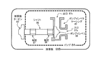
図12Aは、図10Aに示す発電機として使用される膨張機68Aの分解斜視図である。図12Bは、図10Bに示すポンプとして使用される膨張機68Bの分解斜視図である。また、図13Aは、膨張機68Aの概略断面図であり、図13Bは、膨張機68Bの概略断面図である。
FIG. 12A is an exploded perspective view of the
図12A及び図13Aを参照すると、膨張機68Aは、基本的に膨張機タービン80及び発電機82を含む。膨張機タービン80は、膨張機タービンケーシング81の内部に配置されている。発電機82は、発電機ケーシング(図示せず)の内部に配置されている。膨張機68Aは、膨張機タービンケーシング81と発電機ケーシングとを接続するケーシング(図示せず)を更に含む。発電機82は、シャフト90、固定子91、及び回転子92を含む。シャフト90は、シャフト90の長手方向に沿って延びる回転軸周りで回転可能である。シャフト90は、その一端が膨張機タービン80に取り付けられている。固定子91は、例えば発電機ケーシングに固定された不動部材である。回転子92は、固定子91の内部に配置され、シャフト90に固定して連結されている。軸受93及び軸受94は、シャフト90を回転可能に支持するように配置されている。軸受93、94は従来のものであり、従ってここでは詳細に説明及び/又は図示しない。本発明から逸脱することなく、任意の適切な軸受を使用することができることが当業者には明らかであろう。
With reference to FIGS. 12A and 13A, the
動作時、膨張機タービン80は、冷媒から与えられた仕事によって回転され、回転エネルギーが電気エネルギーに変換される。このようにして、膨張機68Aは、冷媒の膨張プロセスにおいて得られたエネルギーによって駆動される発電機として使用される。発生した電力は、チラーシステム10内のインレットガイドベーン、磁気軸受、又は電子膨張メカニズムを駆動させるための動力源として使用することができる。また、発生した電力を貯蔵するために蓄電池を設けることもできる。
During operation, the
図12B及び図13Bを参照すると、膨張機68Bは、基本的に膨張機タービン80及びポンプ84を含む。膨張機タービン80は、膨張機タービンケーシング81の内部に配置されている。ポンプ84は、ポンプインペラ86を含み、ポンプインペラ86は、ポンプインペラケーシング87の内部に配置されている。ポンプインペラケーシング87は、入口87a及び出口87bを有する。膨張機68Bは、膨張機タービンケーシング81とポンプインペラケーシング87とを接続するケーシング(図示せず)を更に含む。ポンプ84は、シャフト96を更に含む。シャフト96は、シャフト96の長手方向に沿って延びる回転軸周りで回転可能である。シャフト96は、その一端で膨張機タービン80に取り付けられ、その他端でポンプインペラ86に取り付けられている。このようにして、膨張機タービン80とポンプ84とは、シャフト96を介して互いに接続される。シャフト96を回転可能に支持するために、軸受97、98が配置されている。軸受97、98は従来のものであり、従ってここでは詳細に説明及び/又は図示しない。本発明から逸脱することなく、任意の適切な軸受を使用することができることが当業者には明らかであろう。
With reference to FIGS. 12B and 13B, the inflator 68B basically includes an
動作時、膨張機タービン80は、冷媒から与えられた仕事によって回転され、膨張機タービン80の回転は、シャフト96を介してポンプインペラ86に伝達される。ポンプインペラ86は、膨張機インペラケーシング87の入口87aから膨張機インペラケーシング87の出口87bに向けて導かれる冷媒の流れを駆動する。出口87bから出た冷媒は、蒸発器に導かれ、蒸発器を通して循環される。次いで、冷媒は再び入口87aに導かれ、再度循環される。このようにして、膨張機68Bは、冷媒の膨張プロセスにおいて得られたエネルギーによって駆動されて冷媒を蒸発器に再循環させるポンプとして使用される。特に、膨張機68Bは、好ましくは、膨張機が流下膜式蒸発器である場合に適用される。流下膜式蒸発器では、伝熱管の外面に液冷媒が上方から付着し、それにより、伝熱管の外面に沿って液冷媒の層又は薄膜が形成される。これには、冷媒の循環を必要とする。
During operation, the
チラーシステム10は、チラーコントローラを含むことができる。このチラーコントローラは従来のものであり、従ってここでは詳細には説明及び/又は図示しない。チラーコントローラは、少なくとも1つのマイクロプロセッサ又はCPUと、入力/出力(I/O)インターフェースと、ランダム・アクセス・メモリ(RAM)と、リード・オンリ・メモリ(ROM)と、(一時又は永久)記憶装置とを備え、1つ以上の制御プログラムを実行することによってチラーシステム10を制御するようにプログラミングされたコンピュータ可読媒体を形成することができる。チラーコントローラは、任意選択で、ユーザからの入力を受け取るためのキーパッド等の入力インターフェースと、ユーザに様々なパラメータを表示するために使用されるディスプレイデバイスとを含むことができる。
The
地球環境保護の観点から、チラーシステムに関して、R1233zd、R1234ze等の新たな低GWP(地球温暖化係数)冷媒の使用が考えられている。低地球温暖化係数の冷媒の一例は、蒸発圧力が大気圧以下の低圧冷媒である。例えば、低圧冷媒R1233zdは、不燃性、無毒性、低コストであり、現在主流の冷媒R134aの代替物質であるR1234ze等の他の候補と比較して高いCOPを有するので、遠心チラー用途の候補である。そのような低圧冷媒は、本発明に係るターボエコノマイザに使用することができる。ただし、本発明に係るターボエコノマイザには、多種の低圧冷媒を使用することができる上、低圧冷媒に限定されるものでもない。
<用語の一般的解釈>
From the viewpoint of protecting the global environment, the use of new low GWP (global warming potential) refrigerants such as R1233zd and R1234ze is considered for the chiller system. An example of a refrigerant having a low global warming potential is a low-pressure refrigerant having an evaporation pressure of atmospheric pressure or less. For example, the low-pressure refrigerant R1233zd is nonflammable, non-toxic, low-cost, and has a high COP compared to other candidates such as R1234ze, which is an alternative substance to the currently mainstream refrigerant R134a, and is therefore a candidate for centrifugal chiller applications. is there. Such a low pressure refrigerant can be used in the turbo economizer according to the present invention. However, the turbo economizer according to the present invention can use various types of low-pressure refrigerants, and is not limited to low-pressure refrigerants.
<General interpretation of terms>
本発明の範囲を理解するにあたって、ここで使用する用語「含む/備える(comprising)」及びその派生語は、上記で述べた特徴、要素、部品、群、数値、及び/又は工程の存在を明記するものであるが、述べていないその他の特徴、要素、部品、群、数値、及び/又は工程の存在を除外しない非限定的用語であることを意図している。また、上記は、用語「備える/含む/有する(including、having)」及びその派生語等の同様の意味を有する単語にも適用される。更に、用語「パーツ(part)」、「セクション(section)」、「部分(portion)」、「部材(member)」、「要素(element)」は、単数形で使用されていても、単数複数双方の意味を有し得る。 In understanding the scope of the invention, the term "comprising" and its derivatives as used herein specify the existence of the features, elements, parts, groups, numbers, and / or processes mentioned above. It is intended to be a non-limiting term that does not preclude the existence of other features, elements, parts, groups, numbers, and / or processes not mentioned. The above also applies to words having similar meanings, such as the term "including / having" and its derivatives. In addition, the terms "part", "section", "portion", "member", and "element" are singular and plural, even when used in the singular. It can have both meanings.
構成要素、セクション、デバイス等によって行われる動作又は機能を述べるために本明細書で使用する用語「検出する(detect)」は、物理的検出を必要とせず、動作又は機能を行うための決定、測定、モデリング、予測、又は演算等を含む構成要素、セクション、デバイス等を含む。 The term "detect" as used herein to describe an action or function performed by a component, section, device, etc. does not require physical detection and is a determination to perform the action or function. Includes components, sections, devices, etc. that include measurement, modeling, prediction, or arithmetic.
装置の部品、セクション、又はパーツの説明のためにここで使用する用語「構成」は、所望の機能を実行するために構築及び/又はプログラミングされたハードウェア及び/又はソフトウェアを含む。 The term "configuration" used herein to describe a component, section, or component of a device includes hardware and / or software built and / or programmed to perform the desired function.
ここで使用する「略(substantially)」、「約(about)」、「およそ(approximately)」等の度合いを示す用語は、最終結果が実質的に変わらないような被修飾語の妥当な偏移量を意味する。 The terms used here to indicate the degree of degree, such as "substantially," "about," and "approximately," are reasonable deviations of the modifier so that the final result does not change substantially. Means quantity.
本発明を説明するために特定の実施形態のみを選択してきたが、添付の請求項において定義される発明の範囲を逸脱することなく種々の変更及び修正がここにおいて可能であることは、本開示から当業者に明らかである。例えば、各種部品のサイズ、形状、場所、又は向きは、必要及び/又は所望に応じて変更可能である。互いに直接的に接続又は接触するように示されている部品は、それらの間に中間構造体を配してもよい。単一要素の機能を、2つの要素で実行可能であり、その逆も同様である。一実施形態の構造及び機能を、別の実施形態で用いてもよい。特定の実施形態に全ての利点が同時に含まれていなくてもよい。従来技術と比べて固有の特徴はすべて、単独としてもその他の特徴との組み合わせとしても、この/これらの特徴によって具体化される構造的及び/又は機能的概念を含む、本出願人による更なる発明の別個の記載として見なされるべきものである。従って、本発明に係る実施形態の上記説明は、単なる例示であり、添付の請求項及びそれらの等価物によって定義される本発明を限定するためのものではない。 Although only certain embodiments have been selected to illustrate the invention, it is disclosed herein that various modifications and modifications are possible without departing from the scope of the invention as defined in the appended claims. It is clear to those skilled in the art. For example, the size, shape, location, or orientation of the various parts can be changed as needed and / or as desired. Parts that are shown to be directly connected or in contact with each other may have intermediate structures placed between them. A single element function can be performed by two elements and vice versa. The structure and function of one embodiment may be used in another embodiment. The particular embodiment may not include all the benefits at the same time. All features unique to the prior art, either alone or in combination with other features, further by Applicant, including structural and / or functional concepts embodied by these features. It should be considered as a separate description of the invention. Therefore, the above description of the embodiments according to the present invention is merely an example and is not intended to limit the present invention as defined by the appended claims and their equivalents.
Claims (14)
前記ターボエコノマイザに冷媒を導くように構成及び配置されたノズルと、
前記ノズルの下流に配置されたタービンであって、回転軸周りで回転可能なシャフトに取り付けられ、前記ノズルを通して導かれる前記冷媒の流れによって駆動されて前記シャフトを回転させるタービンと、
前記シャフトの回転に従って回転されるように前記シャフトに取り付けられたエコノマイザインペラと、
を備え、
前記ノズルは、前記ターボエコノマイザに入る前記冷媒の圧力が前記圧縮機の前記第1段と前記第2段の間に位置する、前記圧縮機の中間段の圧力である中間圧よりも低くなるよう、前記冷媒を減圧するように更に構成及び配置されており、
前記タービンは、前記冷媒をガス冷媒と液冷媒とに分離するように更に構成及び配置されており、
前記タービンにおいて分離された前記ガス冷媒は、前記エコノマイザインペラに導かれ、
前記エコノマイザインペラは、前記エコノマイザインペラ内に導かれる前記冷媒を前記中間圧まで昇圧するように構成及び配置されており、前記エコノマイザインペラで昇圧された前記冷媒は、前記エコノマイザインペラから前記圧縮機の前記中間段に注入され、
前記タービンにおいて分離された前記液冷媒は、前記チラーシステムの前記蒸発器に導かれる、
ターボエコノマイザ。 A turbo adapted for use in chiller systems including compressors, evaporators, and condensers, which are multistage centrifugal compressors including at least first and second stages connected to form a refrigeration circuit. It ’s an economizer,
A nozzle configured and arranged to guide the refrigerant to the turbo economizer,
A turbine arranged downstream of the nozzle, which is attached to a shaft rotatable around a rotation axis and is driven by a flow of the refrigerant guided through the nozzle to rotate the shaft.
An economizer impeller attached to the shaft so that it rotates according to the rotation of the shaft.
With
The nozzle, the pressure of the refrigerant entering the turbo economizer is positioned between the second stage and the first stage of the compressor, it becomes by intermediate pressure remote low a pressure in the intermediate stage of the compressor The refrigerant is further configured and arranged to reduce the pressure.
The turbine is further configured and arranged so as to separate the refrigerant into a gas refrigerant and a liquid refrigerant.
The gas refrigerant separated in the turbine is guided to the economizer impeller.
The economizer impeller, the is configured and arranged to boost the coolant led to the economizer in the impeller by the intermediate pressure or the refrigerant pressurized by the economizer impeller of the compressor from the economizer impeller Injected into the intermediate stage
The liquid refrigerant separated in the turbine is guided to the evaporator of the chiller system.
Turbo economizer.
請求項1に記載のターボエコノマイザ。 The turbo economizer is a refrigerant-powered type that does not use a separate motor, the turbine is driven by the flow of the refrigerant, and the economizer impeller is driven by the driving force from the turbine.
The turbo economizer according to claim 1.
請求項1又は2に記載のターボエコノマイザ。 The nozzles are further configured and arranged to increase the flow rate of the refrigerant.
The turbo economizer according to claim 1 or 2.
請求項1から3のいずれか1項に記載のターボエコノマイザ。 The turbine is configured and arranged to reduce the flow rate of the refrigerant.
The turbo economizer according to any one of claims 1 to 3.
請求項1から4のいずれか1項に記載のターボエコノマイザ。 The turbine is a Pelton wheel turbine,
The turbo economizer according to any one of claims 1 to 4 .
請求項1から5のいずれか1項に記載のターボエコノマイザ。 Further provided with bearings that rotatably support the shaft.
The turbo economizer according to any one of claims 1 to 5 .
前記膨張機は、前記膨張機内に導かれた前記冷媒に対して膨張プロセスを行うように構成及び配置され、
前記膨張プロセスを経た前記冷媒は、前記チラーシステム内の前記蒸発器に導かれる、
請求項1から6のいずれか1項に記載のターボエコノマイザ。 Further equipped with an expander located downstream of the turbine
The expander is configured and arranged to perform an expansion process on the refrigerant guided into the expander.
The refrigerant that has undergone the expansion process is guided to the evaporator in the chiller system.
The turbo economizer according to any one of claims 1 to 6 .
請求項7に記載のターボエコノマイザ。 The inflator includes at least one inflator impeller.
The turbo economizer according to claim 7 .
請求項7又は8に記載のターボエコノマイザ。 The expander is used as a generator driven by the energy obtained in the expansion process of the refrigerant.
The turbo economizer according to claim 7 or 8 .
ターボエコノマイザと、
を備えるチラーシステムであって、
前記ターボエコノマイザは、
前記ターボエコノマイザに冷媒を導くように構成及び配置されたノズルと、
前記ノズルの下流に配置されたタービンであって、回転軸周りで回転可能なシャフトに取り付けられ、前記ノズルを通して導かれる前記冷媒の流れによって駆動されて前記シャフトを回転させるタービンと、
前記シャフトの回転に従って回転されるように前記シャフトに取り付けられたエコノマイザインペラと、
を含み、
前記ノズルは、前記ターボエコノマイザに入る前記冷媒の圧力が前記圧縮機の前記第1段と前記第2段の間に位置する、前記圧縮機の中間段の圧力である中間圧よりも低くなるよう、前記冷媒を減圧するように更に構成及び配置されており、
前記タービンは、前記冷媒をガス冷媒と液冷媒とに分離するように更に構成及び配置されており、
前記タービンにおいて分離された前記ガス冷媒は、前記エコノマイザインペラに導かれ、
前記エコノマイザインペラは、前記エコノマイザインペラ内に導かれる前記冷媒を前記中間圧まで昇圧するように構成及び配置されており、前記エコノマイザインペラで昇圧された前記冷媒は、前記エコノマイザインペラから前記圧縮機の前記中間段に注入され、
前記タービンにおいて分離された前記液冷媒は、前記蒸発器に導かれる、
チラーシステム。 A refrigeration circuit including a compressor, an evaporator, and a condenser, which are multistage centrifugal compressors including at least the first stage and the second stage, which are connected to each other.
With a turbo economizer
It is a chiller system equipped with
The turbo economizer is
A nozzle configured and arranged to guide the refrigerant to the turbo economizer,
A turbine arranged downstream of the nozzle, which is attached to a shaft rotatable around a rotation axis and is driven by a flow of the refrigerant guided through the nozzle to rotate the shaft.
An economizer impeller attached to the shaft so that it rotates according to the rotation of the shaft.
Including
The nozzle, the pressure of the refrigerant entering the turbo economizer is positioned between the second stage and the first stage of the compressor, it becomes by intermediate pressure remote low a pressure in the intermediate stage of the compressor The refrigerant is further configured and arranged to reduce the pressure.
The turbine is further configured and arranged so as to separate the refrigerant into a gas refrigerant and a liquid refrigerant.
The gas refrigerant separated in the turbine is guided to the economizer impeller.
The economizer impeller, the is configured and arranged to boost the coolant led to the economizer in the impeller by the intermediate pressure or the refrigerant pressurized by the economizer impeller of the compressor from the economizer impeller Injected into the middle stage
The liquid refrigerant separated in the turbine is guided to the evaporator.
Chiller system.
請求項10に記載のチラーシステム。 The turbo economizer is located between the evaporator and the condenser in the chiller system.
The chiller system according to claim 10.
前記膨張機は、前記膨張機内に導かれる前記冷媒に対して膨張プロセスを行い、前記膨張プロセスを経た前記冷媒が前記チラーシステム内の前記蒸発器に導かれるように構成及び配置されている、
請求項10又は11に記載のチラーシステム。 The turbo economizer further includes an expander located downstream of the turbine.
The expander is configured and arranged so that an expansion process is performed on the refrigerant guided into the expander, and the refrigerant that has undergone the expansion process is guided to the evaporator in the chiller system.
The chiller system according to claim 10 or 11 .
請求項12に記載のチラーシステム。 The expander is used as a generator driven by the energy obtained in the expansion process of the refrigerant.
Chiller system of claim 1 2.
前記膨張機は、前記冷媒の前記膨張プロセスにおいて得られたエネルギーによって駆動されて前記流下膜式蒸発器を通して前記冷媒を循環させるポンプとして使用される、
請求項12に記載のチラーシステム。 The evaporator is a flow-down membrane type evaporator, and is
The expander is used as a pump that is driven by the energy obtained in the expansion process of the refrigerant to circulate the refrigerant through the downflow membrane evaporator.
Chiller system of claim 1 2.
Applications Claiming Priority (3)
| Application Number | Priority Date | Filing Date | Title |
|---|---|---|---|
| US15/156,548 US10533778B2 (en) | 2016-05-17 | 2016-05-17 | Turbo economizer used in chiller system |
| US15/156,548 | 2016-05-17 | ||
| PCT/US2017/032642 WO2017200916A1 (en) | 2016-05-17 | 2017-05-15 | Turbo economizer used in chiller system |
Publications (2)
| Publication Number | Publication Date |
|---|---|
| JP2019518926A JP2019518926A (en) | 2019-07-04 |
| JP6780024B2 true JP6780024B2 (en) | 2020-11-04 |
Family
ID=58772970
Family Applications (1)
| Application Number | Title | Priority Date | Filing Date |
|---|---|---|---|
| JP2018560885A Active JP6780024B2 (en) | 2016-05-17 | 2017-05-15 | Turbo economizer used in chiller systems |
Country Status (6)
| Country | Link |
|---|---|
| US (1) | US10533778B2 (en) |
| EP (1) | EP3458781B1 (en) |
| JP (1) | JP6780024B2 (en) |
| CN (1) | CN109154456B (en) |
| ES (1) | ES2939859T3 (en) |
| WO (1) | WO2017200916A1 (en) |
Families Citing this family (4)
| Publication number | Priority date | Publication date | Assignee | Title |
|---|---|---|---|---|
| ES2774874A1 (en) * | 2019-01-22 | 2020-07-22 | Cozar Diego Garcia | Energy recovery procedure in refrigeration and air conditioning systems (Machine-translation by Google Translate, not legally binding) |
| CN111219340B (en) * | 2020-03-07 | 2021-04-30 | 山东爱索能源科技有限公司 | Array type miniature gas compressor |
| KR20210136587A (en) | 2020-05-08 | 2021-11-17 | 엘지전자 주식회사 | A turbo compressor and a turbo chiller including the same |
| JP7448844B2 (en) * | 2022-04-26 | 2024-03-13 | ダイキン工業株式会社 | Heat exchanger and refrigeration equipment |
Family Cites Families (17)
| Publication number | Priority date | Publication date | Assignee | Title |
|---|---|---|---|---|
| US4170116A (en) * | 1975-10-02 | 1979-10-09 | Williams Kenneth A | Method and apparatus for converting thermal energy to mechanical energy |
| JPS5855655A (en) * | 1981-09-30 | 1983-04-02 | 株式会社東芝 | Turbine for refrigerating cycle |
| SE8803595L (en) | 1988-10-11 | 1990-04-12 | Svenska Rotor Maskiner Ab | MACHINE CONTAINS A GAS MEDIUM |
| US5347823A (en) * | 1990-04-06 | 1994-09-20 | Alsenz Richard H | Refrigeration system utilizing an enthalpy expansion jet compressor |
| US5664420A (en) * | 1992-05-05 | 1997-09-09 | Biphase Energy Company | Multistage two-phase turbine |
| US5317882A (en) * | 1993-04-27 | 1994-06-07 | Ritenour Paul E | Unique water vapor vacuum refrigeration system |
| US5561987A (en) * | 1995-05-25 | 1996-10-08 | American Standard Inc. | Falling film evaporator with vapor-liquid separator |
| FR2776341B1 (en) * | 1998-03-23 | 2000-06-09 | Gec Alsthom Neyrpic | TURBINE WHEEL AND PELTON-TYPE TURBINE EQUIPPED WITH SUCH A WHEEL |
| US6185956B1 (en) | 1999-07-09 | 2001-02-13 | Carrier Corporation | Single rotor expressor as two-phase flow throttle valve replacement |
| US6644045B1 (en) * | 2002-06-25 | 2003-11-11 | Carrier Corporation | Oil free screw expander-compressor |
| US6644062B1 (en) * | 2002-10-15 | 2003-11-11 | Energent Corporation | Transcritical turbine and method of operation |
| US6898941B2 (en) * | 2003-06-16 | 2005-05-31 | Carrier Corporation | Supercritical pressure regulation of vapor compression system by regulation of expansion machine flowrate |
| US8863547B2 (en) * | 2006-04-05 | 2014-10-21 | Ben M. Enis | Desalination method and system using compressed air energy systems |
| WO2008063256A1 (en) | 2006-10-26 | 2008-05-29 | Johnson Controls Technology Company | Economized refrigeration system |
| CN101568770A (en) * | 2006-12-26 | 2009-10-28 | 开利公司 | CO2 refrigerant system with tandem compressors, expander and economizer |
| CN101270929A (en) * | 2008-04-01 | 2008-09-24 | 中国科学院广州能源研究所 | Expansion-compression integrated device for refrigerating system |
| JP5195485B2 (en) * | 2009-02-09 | 2013-05-08 | 株式会社Ihi | Multistage turbo compressor |
-
2016
- 2016-05-17 US US15/156,548 patent/US10533778B2/en active Active
-
2017
- 2017-05-15 CN CN201780030100.0A patent/CN109154456B/en active Active
- 2017-05-15 EP EP17726065.0A patent/EP3458781B1/en active Active
- 2017-05-15 JP JP2018560885A patent/JP6780024B2/en active Active
- 2017-05-15 ES ES17726065T patent/ES2939859T3/en active Active
- 2017-05-15 WO PCT/US2017/032642 patent/WO2017200916A1/en unknown
Also Published As
| Publication number | Publication date |
|---|---|
| CN109154456B (en) | 2020-12-22 |
| EP3458781A1 (en) | 2019-03-27 |
| US20170336106A1 (en) | 2017-11-23 |
| EP3458781B1 (en) | 2023-01-18 |
| JP2019518926A (en) | 2019-07-04 |
| ES2939859T3 (en) | 2023-04-27 |
| CN109154456A (en) | 2019-01-04 |
| WO2017200916A1 (en) | 2017-11-23 |
| US10533778B2 (en) | 2020-01-14 |
Similar Documents
| Publication | Publication Date | Title |
|---|---|---|
| JP6806878B2 (en) | Magnetic bearing backup system for centrifugal compressors and centrifugal compressors | |
| JP6780024B2 (en) | Turbo economizer used in chiller systems | |
| US10794619B2 (en) | Compressor with motor cooling | |
| CN108700345B (en) | Economizer and cooler system | |
| US10648702B2 (en) | Low capacity, low-GWP, HVAC system | |
| JP2009264305A (en) | Centrifugal compressor and turbo refrigerating machine using the same | |
| JP5326900B2 (en) | Turbo compressor and refrigerator | |
| US11781561B2 (en) | Compressor and chiller including the same | |
| KR20190044615A (en) | Refrigerant compressor | |
| JP2005527778A (en) | Expansion drive motor for auxiliary machine | |
| US20220082338A1 (en) | Heat transfer pipe and heat exchanger for chiller | |
| JP2019211170A (en) | Refrigeration cycle device | |
| CN207246078U (en) | A kind of centrifugal compressor of cooling device | |
| JPWO2014196497A1 (en) | Turbo refrigerator |
Legal Events
| Date | Code | Title | Description |
|---|---|---|---|
| A621 | Written request for application examination |
Free format text: JAPANESE INTERMEDIATE CODE: A621 Effective date: 20190121 |
|
| A977 | Report on retrieval |
Free format text: JAPANESE INTERMEDIATE CODE: A971007 Effective date: 20191213 |
|
| A131 | Notification of reasons for refusal |
Free format text: JAPANESE INTERMEDIATE CODE: A131 Effective date: 20200114 |
|
| A521 | Request for written amendment filed |
Free format text: JAPANESE INTERMEDIATE CODE: A523 Effective date: 20200413 |
|
| TRDD | Decision of grant or rejection written | ||
| A01 | Written decision to grant a patent or to grant a registration (utility model) |
Free format text: JAPANESE INTERMEDIATE CODE: A01 Effective date: 20200915 |
|
| A61 | First payment of annual fees (during grant procedure) |
Free format text: JAPANESE INTERMEDIATE CODE: A61 Effective date: 20201014 |
|
| R150 | Certificate of patent or registration of utility model |
Ref document number: 6780024 Country of ref document: JP Free format text: JAPANESE INTERMEDIATE CODE: R150 |
|
| S111 | Request for change of ownership or part of ownership |
Free format text: JAPANESE INTERMEDIATE CODE: R313113 |
|
| R360 | Written notification for declining of transfer of rights |
Free format text: JAPANESE INTERMEDIATE CODE: R360 |
|
| R360 | Written notification for declining of transfer of rights |
Free format text: JAPANESE INTERMEDIATE CODE: R360 |
|
| R371 | Transfer withdrawn |
Free format text: JAPANESE INTERMEDIATE CODE: R371 |
|
| S111 | Request for change of ownership or part of ownership |
Free format text: JAPANESE INTERMEDIATE CODE: R313113 |
|
| R350 | Written notification of registration of transfer |
Free format text: JAPANESE INTERMEDIATE CODE: R350 |