JP6779670B2 - Electronic endoscopy system - Google Patents
Electronic endoscopy system Download PDFInfo
- Publication number
- JP6779670B2 JP6779670B2 JP2016118385A JP2016118385A JP6779670B2 JP 6779670 B2 JP6779670 B2 JP 6779670B2 JP 2016118385 A JP2016118385 A JP 2016118385A JP 2016118385 A JP2016118385 A JP 2016118385A JP 6779670 B2 JP6779670 B2 JP 6779670B2
- Authority
- JP
- Japan
- Prior art keywords
- image signal
- image
- signal
- luminance
- band light
- Prior art date
- Legal status (The legal status is an assumption and is not a legal conclusion. Google has not performed a legal analysis and makes no representation as to the accuracy of the status listed.)
- Active
Links
Images


Classifications
-
- A—HUMAN NECESSITIES
- A61—MEDICAL OR VETERINARY SCIENCE; HYGIENE
- A61B—DIAGNOSIS; SURGERY; IDENTIFICATION
- A61B1/00—Instruments for performing medical examinations of the interior of cavities or tubes of the body by visual or photographical inspection, e.g. endoscopes; Illuminating arrangements therefor
- A61B1/06—Instruments for performing medical examinations of the interior of cavities or tubes of the body by visual or photographical inspection, e.g. endoscopes; Illuminating arrangements therefor with illuminating arrangements
- A61B1/0638—Instruments for performing medical examinations of the interior of cavities or tubes of the body by visual or photographical inspection, e.g. endoscopes; Illuminating arrangements therefor with illuminating arrangements providing two or more wavelengths
-
- A—HUMAN NECESSITIES
- A61—MEDICAL OR VETERINARY SCIENCE; HYGIENE
- A61B—DIAGNOSIS; SURGERY; IDENTIFICATION
- A61B1/00—Instruments for performing medical examinations of the interior of cavities or tubes of the body by visual or photographical inspection, e.g. endoscopes; Illuminating arrangements therefor
- A61B1/00002—Operational features of endoscopes
- A61B1/00004—Operational features of endoscopes characterised by electronic signal processing
- A61B1/00009—Operational features of endoscopes characterised by electronic signal processing of image signals during a use of endoscope
- A61B1/000095—Operational features of endoscopes characterised by electronic signal processing of image signals during a use of endoscope for image enhancement
-
- A—HUMAN NECESSITIES
- A61—MEDICAL OR VETERINARY SCIENCE; HYGIENE
- A61B—DIAGNOSIS; SURGERY; IDENTIFICATION
- A61B1/00—Instruments for performing medical examinations of the interior of cavities or tubes of the body by visual or photographical inspection, e.g. endoscopes; Illuminating arrangements therefor
- A61B1/00002—Operational features of endoscopes
- A61B1/00043—Operational features of endoscopes provided with output arrangements
- A61B1/00045—Display arrangement
- A61B1/0005—Display arrangement combining images e.g. side-by-side, superimposed or tiled
-
- A—HUMAN NECESSITIES
- A61—MEDICAL OR VETERINARY SCIENCE; HYGIENE
- A61B—DIAGNOSIS; SURGERY; IDENTIFICATION
- A61B1/00—Instruments for performing medical examinations of the interior of cavities or tubes of the body by visual or photographical inspection, e.g. endoscopes; Illuminating arrangements therefor
- A61B1/04—Instruments for performing medical examinations of the interior of cavities or tubes of the body by visual or photographical inspection, e.g. endoscopes; Illuminating arrangements therefor combined with photographic or television appliances
- A61B1/045—Control thereof
-
- A—HUMAN NECESSITIES
- A61—MEDICAL OR VETERINARY SCIENCE; HYGIENE
- A61B—DIAGNOSIS; SURGERY; IDENTIFICATION
- A61B1/00—Instruments for performing medical examinations of the interior of cavities or tubes of the body by visual or photographical inspection, e.g. endoscopes; Illuminating arrangements therefor
- A61B1/04—Instruments for performing medical examinations of the interior of cavities or tubes of the body by visual or photographical inspection, e.g. endoscopes; Illuminating arrangements therefor combined with photographic or television appliances
- A61B1/05—Instruments for performing medical examinations of the interior of cavities or tubes of the body by visual or photographical inspection, e.g. endoscopes; Illuminating arrangements therefor combined with photographic or television appliances characterised by the image sensor, e.g. camera, being in the distal end portion
-
- A—HUMAN NECESSITIES
- A61—MEDICAL OR VETERINARY SCIENCE; HYGIENE
- A61B—DIAGNOSIS; SURGERY; IDENTIFICATION
- A61B1/00—Instruments for performing medical examinations of the interior of cavities or tubes of the body by visual or photographical inspection, e.g. endoscopes; Illuminating arrangements therefor
- A61B1/06—Instruments for performing medical examinations of the interior of cavities or tubes of the body by visual or photographical inspection, e.g. endoscopes; Illuminating arrangements therefor with illuminating arrangements
- A61B1/063—Instruments for performing medical examinations of the interior of cavities or tubes of the body by visual or photographical inspection, e.g. endoscopes; Illuminating arrangements therefor with illuminating arrangements for monochromatic or narrow-band illumination
-
- G—PHYSICS
- G02—OPTICS
- G02B—OPTICAL ELEMENTS, SYSTEMS OR APPARATUS
- G02B23/00—Telescopes, e.g. binoculars; Periscopes; Instruments for viewing the inside of hollow bodies; Viewfinders; Optical aiming or sighting devices
- G02B23/24—Instruments or systems for viewing the inside of hollow bodies, e.g. fibrescopes
- G02B23/2407—Optical details
- G02B23/2423—Optical details of the distal end
-
- G—PHYSICS
- G02—OPTICS
- G02B—OPTICAL ELEMENTS, SYSTEMS OR APPARATUS
- G02B23/00—Telescopes, e.g. binoculars; Periscopes; Instruments for viewing the inside of hollow bodies; Viewfinders; Optical aiming or sighting devices
- G02B23/24—Instruments or systems for viewing the inside of hollow bodies, e.g. fibrescopes
- G02B23/2407—Optical details
- G02B23/2461—Illumination
-
- H—ELECTRICITY
- H04—ELECTRIC COMMUNICATION TECHNIQUE
- H04N—PICTORIAL COMMUNICATION, e.g. TELEVISION
- H04N7/00—Television systems
- H04N7/18—Closed-circuit television [CCTV] systems, i.e. systems in which the video signal is not broadcast
-
- A—HUMAN NECESSITIES
- A61—MEDICAL OR VETERINARY SCIENCE; HYGIENE
- A61B—DIAGNOSIS; SURGERY; IDENTIFICATION
- A61B1/00—Instruments for performing medical examinations of the interior of cavities or tubes of the body by visual or photographical inspection, e.g. endoscopes; Illuminating arrangements therefor
- A61B1/00064—Constructional details of the endoscope body
- A61B1/00071—Insertion part of the endoscope body
- A61B1/0008—Insertion part of the endoscope body characterised by distal tip features
- A61B1/00096—Optical elements
Description
本発明は、電子内視鏡システムに関する。 The present invention relates to an electronic endoscopy system.
被写体の明るい部位から暗い部位までを鮮明に表示するようにダイナミックレンジを拡張したHDR(High Dynamic Range)画像を生成する電子内視鏡システムが知られている。HDR画像を得るためには、被写体を高い露出値で撮像することによって得られる高輝度画像信号と、これと同じ被写体を低い露出値で撮像することによって得られる低輝度画像信号とを合成する必要がある。例えば特許文献1に、HDR画像を生成することが可能な電子内視鏡システムの具体的構成が記載されている。
An electronic endoscope system that generates an HDR (High Dynamic Range) image with an expanded dynamic range so as to clearly display a bright part to a dark part of a subject is known. In order to obtain an HDR image, it is necessary to combine a high-brightness image signal obtained by imaging a subject with a high exposure value and a low-brightness image signal obtained by imaging the same subject with a low exposure value. There is. For example,
特許文献1に記載の電子内視鏡システムでは、光源の発光時間が1フィールド毎に交互に切り替わる。光源の発光時間が長いフィールドでは撮像素子の受光量が多くなり、光源の発光時間が短いフィールドでは撮像素子の受光量が少なくなる。そのため、前者のフィールドでは高輝度画像信号が得られ、後者のフィールドでは低輝度画像信号が得られる。特許文献1に記載の電子内視鏡システムでは、これらの画像信号を用いてHDR画像が生成される。
In the electronic endoscope system described in
近年、特定の生体構造に高い吸収特性を持つ狭帯域光を用いて特定の生体構造を強調した狭帯域光観察画像を生成する電子内視鏡システムが知られている。一般に、狭帯域光は、白色光源より射出された白色光を光学フィルタで半値幅の狭い光にフィルタリングしたものであることから、白色光と比べて光量が極端に少ない。そのため、狭帯域光を用いた場合には、被写体を明るく撮像することが難しく、HDR画像の生成に必要な高輝度画像信号を得ることが難しい。 In recent years, an electron endoscopy system has been known that generates a narrow-band light observation image in which a specific biological structure is emphasized by using narrow-band light having high absorption characteristics in a specific biological structure. In general, narrow band light has an extremely small amount of light as compared with white light because white light emitted from a white light source is filtered by an optical filter to light having a narrow half width. Therefore, when narrow band light is used, it is difficult to image the subject brightly, and it is difficult to obtain a high-luminance image signal necessary for generating an HDR image.
本発明は上記の事情に鑑みてなされたものであり、その目的とするところは、狭帯域光により照射された被写体の特定の生体構造を強調したHDR画像を生成するのに好適な電子内視鏡システムを提供することである。 The present invention has been made in view of the above circumstances, and an object of the present invention is an electronic endoscopy suitable for generating an HDR image emphasizing a specific biological structure of a subject irradiated with narrow band light. To provide a mirror system.
本発明の一実施形態に係る電子内視鏡システムは、狭帯域光と広帯域光とを交互に射出する光源部と、狭帯域光と広帯域光とで交互に照射される被写体を撮像し、該狭帯域光の照射期間中に撮像された被写体の画像信号を第一画像信号として生成すると共に、該広帯域光の照射期間中に撮像された被写体の画像信号を第二画像信号として生成する手段と、第一画像信号と第二画像信号とを加算して高輝度画像信号を生成する高輝度画像信号生成手段と、第一画像信号と、所定の係数で乗算することによって信号レベルを低下させた第二画像信号とを加算して低輝度画像信号を生成する低輝度画像信号生成手段と、高輝度画像信号と低輝度画像信号を用いてHDR画像信号を生成するHDR画像信号生成手段とを備える。 The electronic endoscopy system according to the embodiment of the present invention captures an image of a light source unit that alternately emits narrow-band light and wide-band light, and a subject that is alternately irradiated with narrow-band light and wide-band light. As a means for generating the image signal of the subject captured during the irradiation period of the narrow band light as the first image signal and the image signal of the subject captured during the irradiation period of the broadband light as the second image signal. , The signal level was lowered by multiplying the first image signal by a high-luminance image signal generation means for generating a high-luminance image signal by adding the first image signal and the second image signal by a predetermined coefficient. The present invention includes a low-luminance image signal generation means for generating a low-luminance image signal by adding a second image signal, and an HDR image signal generation means for generating an HDR image signal using the high-luminance image signal and the low-luminance image signal. ..
また、本発明の一実施形態において、高輝度画像信号生成手段、低輝度画像信号生成手段は、それぞれ、時間的に隣り合う照射期間中に撮像された被写体の第一画像信号と第二画像信号を用いて高輝度画像信号、低輝度画像信号を生成する構成としてもよい。 Further, in one embodiment of the present invention, the high-luminance image signal generation means and the low-luminance image signal generation means are the first image signal and the second image signal of the subject imaged during the irradiation period adjacent in time, respectively. May be used to generate a high-luminance image signal and a low-luminance image signal.
また、本発明の一実施形態において、第二画像信号に乗算される所定の係数は、例えば定数であり、また、第一画像信号と第二画像信号との信号レベル比に基づいて設定される値であってもよい。 Further, in one embodiment of the present invention, the predetermined coefficient to be multiplied by the second image signal is, for example, a constant, and is set based on the signal level ratio between the first image signal and the second image signal. It may be a value.
本発明の一実施形態によれば、狭帯域光により照射された被写体の特定の生体構造を強調したHDR画像を生成するのに好適な電子内視鏡システムが提供される。 According to one embodiment of the present invention, there is provided an electronic endoscopy system suitable for generating an HDR image that emphasizes a specific biological structure of a subject irradiated with narrow band light.
以下、本発明の実施形態について図面を参照しながら説明する。なお、以下においては、本発明の一実施形態として電子内視鏡システムを例に取り説明する。 Hereinafter, embodiments of the present invention will be described with reference to the drawings. In the following, an electronic endoscope system will be described as an example of an embodiment of the present invention.
図1は、本発明の一実施形態に係る電子内視鏡システム1の構成を示すブロック図である。図1に示されるように、電子内視鏡システム1は、医療用に特化されたシステムであり、電子スコープ100、プロセッサ200及びモニタ300を備えている。
FIG. 1 is a block diagram showing a configuration of an
プロセッサ200は、システムコントローラ202及びタイミングコントローラ204を備えている。システムコントローラ202は、メモリ212に記憶された各種プログラムを実行し、電子内視鏡システム1全体を統合的に制御する。
The
また、システムコントローラ202は、操作パネル214に接続されている。システムコントローラ202は、操作パネル214より入力される術者からの指示に応じて、電子内視鏡システム1の各動作の実行及び各動作のためのパラメータの変更を行う。術者による入力指示には、例えば電子内視鏡システム1の動作モードの切替指示がある。動作モードには、例えば通常モードやHDRモードがある。タイミングコントローラ204は、各部の動作のタイミングを調整するクロックパルスを電子内視鏡システム1内の各回路に出力する。
Further, the
ランプ208は、ランプ電源イグナイタ206による始動後、照射光Lを射出する。ランプ208は、例えば、キセノンランプ、ハロゲンランプ、水銀ランプ、メタルハライドランプ等の高輝度ランプであり、また、LD(Laser Diode)やLED(Light Emitting Diode)等の半導体発光素子であってもよい。照射光Lは、少なくとも可視光領域を含む光(白色光)である。
The lamp 208 emits irradiation light L after being started by the
ランプ208より射出された照射光Lは、回転フィルタ部260に入射される。図2は、回転フィルタ部260を集光レンズ210側から見た正面図である。回転フィルタ部260は、回転式ターレット261、DCモータ262、ドライバ263及びフォトインタラプタ264を備えている。
The irradiation light L emitted from the lamp 208 is incident on the
図2に示されるように、回転式ターレット261には、狭帯域光用フィルタFnbと白色光用フィルタFwが円周方向に交互に並べて配置されている。各光学フィルタは扇形状を有しており、フレーム周期に応じた角度ピッチ(ここでは、約90°の角度ピッチ)で配置されている。なお、以降の説明において「フレーム」は「フィールド」に置き替えてもよい。
As shown in FIG. 2, in the
ドライバ263は、システムコントローラ202による制御下でDCモータ262を駆動する。回転フィルタ部260は、回転式ターレット261がDCモータ262によって回転動作することにより、ランプ208より入射された照射光Lから、スペクトルの異なる二種類の照射光(狭帯域光Lnbと白色光Lw)の一方を、撮像と同期したタイミングで取り出す。
The
具体的には、回転式ターレット261は、回転動作中、狭帯域光用フィルタFnbから狭帯域光Lnbを、白色光用フィルタFwから狭帯域光Lnbよりも帯域の広い広帯域光(白色光Lw)を、交互に取り出す。回転式ターレット261の回転位置や回転の位相は、回転式ターレット261の外周付近に形成された開口(不図示)をフォトインタラプタ264によって検出することにより制御される。
Specifically, the
狭帯域光用フィルタFnbは、特定の生体構造(表層や深層の血管構造、特定の病変部位等)を強調した狭帯域光観察画像を撮影するのに適した分光特性を持つ。照射光Lは、狭帯域光用フィルタFnbを通過することにより、特定の生体構造に高い吸収特性を持つ半値幅の狭い光、すなわち狭帯域光Lnbとなる。 The narrow-band light filter Fnb has spectral characteristics suitable for capturing a narrow-band light observation image that emphasizes a specific biological structure (surface layer or deep blood vessel structure, specific lesion site, etc.). By passing through the narrow-band light filter Fnb, the irradiation light L becomes light having a narrow half-value width having high absorption characteristics in a specific biological structure, that is, narrow-band light Lnb.
白色光用フィルタFwは、照射光Lを適正な光量に減光する減光フィルタである。なお、白色光用フィルタFwは、単なる開口(光学フィルタの無いもの)や絞り機能を兼ねたスリット(光学フィルタの無いもの)に置き換えてもよい。 The white light filter Fw is a dimming filter that dims the irradiation light L to an appropriate amount of light. The white light filter Fw may be replaced with a simple aperture (without an optical filter) or a slit (without an optical filter) having a diaphragm function.
回転フィルタ部260より取り出された照射光(狭帯域光Lnb又は白色光Lw)は、集光レンズ210により、電子スコープ100のLCB(Light Carrying Bundle)102の入射端面に集光されてLCB102内に入射される。
The irradiation light (narrow band light Lnb or white light Lw) extracted from the
LCB102内に入射された照射光(狭帯域光Lnb又は白色光Lw)は、LCB102内を伝播して電子スコープ100の先端に配置されたLCB102の射出端面より射出され、配光レンズ104を介して被写体である体腔内の生体組織に照射される。これにより、生体組織は、狭帯域光Lnbと白色光Lwとによって交互に照射される。照射光により照射された生体組織からの戻り光は、対物レンズ106を介して固体撮像素子108の受光面上で光学像を結ぶ。
The irradiation light (narrow band light Lnb or white light Lw) incident on the
固体撮像素子108は、ベイヤ型画素配置を有する単板式カラーCCD(Charge Coupled Device)イメージセンサである。固体撮像素子108は、受光面上の各画素で結像した光学像を光量に応じた電荷として蓄積して、R(Red)、G(Green)、B(Blue)の画像信号を生成して出力する。なお、固体撮像素子108は、CCDイメージセンサに限らず、CMOS(Complementary Metal Oxide Semiconductor)イメージセンサやその他の種類の撮像装置に置き換えられてもよい。固体撮像素子108はまた、補色系フィルタを搭載したものであってもよい。
The solid-
回転フィルタ部260による狭帯域光Lnbと白色光Lwとの切り換えのタイミングは、固体撮像素子108における撮像期間(フレーム期間)の切り換えのタイミングと同期している。従って、固体撮像素子108は、1フレーム期間中、狭帯域光Lnbにより照射された生体組織からの戻り光を受光して狭帯域光観察像の画像信号を生成して出力し、続く1フレーム期間中、白色光Lwにより照射された生体組織からの戻り光を受光して白色光観察像の画像信号を生成して出力する。固体撮像素子108は、上記を繰り返すことにより、各観察像の画像信号を交互に出力する。
The timing of switching between the narrow band light Lnb and the white light Lw by the
電子スコープ100の接続部内には、ドライバ信号処理回路110が備えられている。ドライバ信号処理回路110には、狭帯域光観察像、白色光観察像の各画像信号がフレーム周期で固体撮像素子108より入力される。ドライバ信号処理回路110は、固体撮像素子108より入力される画像信号に対して所定の処理を施してプロセッサ200の信号処理回路220に出力する。
A driver
ドライバ信号処理回路110はまた、メモリ112にアクセスして電子スコープ100の固有情報を読み出す。メモリ112に記録される電子スコープ100の固有情報には、例えば、固体撮像素子108の画素数や感度、動作可能なフレームレート、型番等が含まれる。ドライバ信号処理回路110は、メモリ112より読み出された固有情報をシステムコントローラ202に出力する。
The driver
システムコントローラ202は、電子スコープ100の固有情報に基づいて各種演算を行い、制御信号を生成する。システムコントローラ202は、生成された制御信号を用いて、プロセッサ200に接続されている電子スコープに適した処理がなされるようにプロセッサ200内の各種回路の動作やタイミングを制御する。
The
タイミングコントローラ204は、システムコントローラ202によるタイミング制御に従って、ドライバ信号処理回路110にクロックパルスを供給する。ドライバ信号処理回路110は、タイミングコントローラ204から供給されるクロックパルスに従って、固体撮像素子108をプロセッサ200側で処理される映像のフレームレートに同期したタイミングで駆動制御する。
The
信号処理回路220は、前段信号処理回路222、HDR画像生成回路224、後段信号処理回路226及び画像メモリ228を有している。信号処理回路220の信号処理動作については、電子内視鏡システム1の動作モードが通常モードに設定されている場合と、HDRモードに設定されている場合に分けて説明する。
The
[動作モードが通常モードに設定されている場合]
前段信号処理回路222は、ドライバ信号処理回路110より1フレーム周期で交互に入力される狭帯域光観察像、白色光観察像の各画像信号に対して、デモザイク処理、マトリックス演算、Y/C分離等の所定の信号処理を施して、HDR画像生成回路224に出力する。
[When the operation mode is set to normal mode]
The pre-stage
HDR画像生成回路224は、前段信号処理回路222より1フレーム周期で交互に入力される狭帯域光観察像、白色光観察像の各画像信号を後段信号処理回路226にスルー出力する。
The HDR
後段信号処理回路226は、HDR画像生成回路224より1フレーム周期で交互に入力される狭帯域光観察像、白色光観察像の各画像信号を処理してモニタ表示用の画面データを生成し、生成されたモニタ表示用の画面データを所定のビデオフォーマット信号に変換する。変換されたビデオフォーマット信号は、モニタ300に出力される。これにより、生体組織の狭帯域光観察画像や白色光観察画像がモニタ300の表示画面に表示される。
The subsequent
[動作モードがHDRモードに設定されている場合]
図3に、HDRモード時の信号処理回路220の信号処理動作をフローチャートで示す。図3に示されるフローチャートは、例えば、電子内視鏡システム1の動作モードがHDRモードに切り替えられた時点で開始される。
[When the operation mode is set to HDR mode]
FIG. 3 is a flowchart showing the signal processing operation of the
[図3のS11(現フレームの画像信号の入力)]
本処理ステップS11では、現フレームの画像信号(狭帯域光観察像又は白色光観察像の画像信号)が前段信号処理回路222に入力される。
[S11 in FIG. 3 (input of image signal of the current frame)]
In this processing step S11, the image signal of the current frame (the image signal of the narrow band light observation image or the white light observation image) is input to the pre-stage
[図3のS12(画像信号の判定)]
本処理ステップS12では、HDR画像生成回路224において、処理ステップS11(現フレームの画像信号の入力)にて前段信号処理回路222より入力された現フレームの画像信号が、狭帯域光観察像、白色光観察像の何れの画像信号であるかが判定される。HDR画像生成回路224は、例えば、システムコントローラ202による回転フィルタ部260等の制御情報や画像信号の平均輝度値等を基に、現フレームの画像信号が狭帯域光観察像、白色光観察像の何れの画像信号であるかを判定する。
[S12 in FIG. 3 (determination of image signal)]
In the present processing step S12, in the HDR
[図3のS13(前フレームの画像信号の読み出し)]
画像メモリ228(揮発性メモリ)には、後述の処理ステップS18(現フレームの画像信号の保持)の実行により、前フレーム(現フレームの1つ前のフレーム)の画像信号が保持されている。本処理ステップS13では、HDR画像生成回路224により、前フレームの画像信号が画像メモリ228から読み出される。現フレームの画像信号が狭帯域光観察像の画像信号である場合には、白色光観察像の画像信号が読み出され、現フレームの画像信号が白色光観察像の画像信号である場合には、狭帯域光観察像の画像信号が読み出される。
[S13 in FIG. 3 (reading the image signal of the previous frame)]
The image signal of the previous frame (the frame immediately before the current frame) is held in the image memory 228 (volatile memory) by executing the processing step S18 (holding the image signal of the current frame) described later. In this processing step S13, the HDR
なお、電子内視鏡システム1の起動時に動作モードがHDRモードに設定されている場合、本フローチャートに示される処理の初回実行時には、前フレームの画像信号が画像メモリ228に保持されていない。この場合、本フローチャートの処理は、後述の処理ステップS18(現フレームの画像信号の保持)に進む。
When the operation mode is set to the HDR mode when the
[図3のS14(高輝度画像信号の生成)]
本処理ステップS14では、HDR画像生成回路224において、現フレームの画像信号と処理ステップS13(前フレームの画像信号の読み出し)にて読み出された前フレームの画像信号とが加算されることにより、高輝度画像信号が生成される。
[S14 of FIG. 3 (generation of high-luminance image signal)]
In the present processing step S14, in the HDR
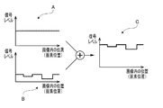
図4に、高輝度画像信号を生成する処理の概念的な説明図を示す。図4のグラフAは、白色光観察像の画像信号を構成する各画素の信号レベル(輝度値)を概念的に示す。図4のグラフAは、例えば、粘膜等の表面部分を写す画素の信号レベルを示すものとなっている。また、図4のグラフBは、狭帯域光観察像の画像信号を構成する各画素の信号レベルを概念的に示す。図4のグラフBは、例えば、粘膜等の表面部分に加えて特定の生体構造を写す画素の信号レベルを示すものとなっている。グラフB中、落ち込んでいる2か所が特定の生体構造を写す画素に対応し、それ以外が粘膜等を写す画素に対応する。このように、グラフBには、特定の生体構造の情報が含まれる。 FIG. 4 shows a conceptual explanatory diagram of a process for generating a high-luminance image signal. Graph A of FIG. 4 conceptually shows the signal level (luminance value) of each pixel constituting the image signal of the white light observation image. Graph A in FIG. 4 shows, for example, the signal level of a pixel that captures a surface portion such as a mucous membrane. Further, Graph B in FIG. 4 conceptually shows the signal level of each pixel constituting the image signal of the narrow band optical observation image. Graph B in FIG. 4 shows, for example, the signal level of a pixel that captures a specific biological structure in addition to a surface portion such as a mucous membrane. In the graph B, two depressed parts correspond to pixels that show a specific biological structure, and the other parts correspond to pixels that show a mucous membrane or the like. As described above, the graph B includes information on a specific biological structure.
図4の例では、白色光観察像の画像信号(図4のグラフA参照)と狭帯域光観察像の画像信号(図4のグラフB参照)とが加算されると、図4のグラフCに示されるように、狭帯域光観察像の画像信号の信号レベルが特定の生体構造の情報を保持しつつ加算分(白色光観察像の画像信号の信号レベル分)上がる。これにより、高輝度な画像信号、すなわち高輝度画像信号が得られる。 In the example of FIG. 4, when the image signal of the white light observation image (see graph A of FIG. 4) and the image signal of the narrow band light observation image (see graph B of FIG. 4) are added, the graph C of FIG. As shown in, the signal level of the image signal of the narrow-band light observation image is increased by the addition amount (the signal level of the image signal of the white light observation image) while retaining the information of the specific biological structure. As a result, a high-luminance image signal, that is, a high-luminance image signal can be obtained.
[図3のS15(低輝度画像信号の生成)]
本処理ステップS15では、HDR画像生成回路224において、処理ステップS12(画像信号の判定)にて現フレームの画像信号が白色光観察像の画像信号であると判定された場合には、現フレームの画像信号が係数αで乗算され、同処理ステップにて現フレームの画像信号が狭帯域光観察像の画像信号であると判定された場合には、前フレームの画像信号(すなわち、白色光観察像の画像信号)が係数αで乗算される。
[S15 of FIG. 3 (generation of low-luminance image signal)]
In the present processing step S15, when the HDR
係数αは、1未満の値である。そのため、白色光観察像の画像信号は、係数αで乗算されることにより、信号レベルが下がる(減衰される)。本処理ステップS15では、係数αで乗算された白色光観察像の画像信号と、狭帯域光観察像の画像信号とが加算されることにより、低輝度画像信号が生成される。 The coefficient α is a value less than 1. Therefore, the signal level of the image signal of the white light observation image is lowered (attenuated) by being multiplied by the coefficient α. In this processing step S15, a low-luminance image signal is generated by adding the image signal of the white light observation image multiplied by the coefficient α and the image signal of the narrow-band light observation image.
図5に、低輝度画像信号を生成する処理の概念的な説明図を示す。図5のグラフDは、白色光観察像の画像信号を構成する各画素の信号レベルを概念的に示すものであって、図4のグラフAに示される各画素の信号レベルを係数αで乗算したものを示す。図5のグラフDから、白色光観察像の画像信号が係数αで乗算されることで信号レベルが下がり、低輝度になっていることが判る。また、図5のグラフEは、図4のグラフBと同じである。 FIG. 5 shows a conceptual explanatory diagram of a process for generating a low-luminance image signal. Graph D in FIG. 5 conceptually shows the signal level of each pixel constituting the image signal of the white light observation image, and the signal level of each pixel shown in graph A in FIG. 4 is multiplied by a coefficient α. Show what you did. From the graph D of FIG. 5, it can be seen that the signal level is lowered and the brightness is lowered by multiplying the image signal of the white light observation image by the coefficient α. Further, the graph E in FIG. 5 is the same as the graph B in FIG.
図5の例では、白色光観察像の画像信号(図5のグラフD参照)と狭帯域光観察像の画像信号(図5のグラフE参照)とが加算されると、図5のグラフFに示されるように、狭帯域光観察像の画像信号の信号レベルが特定の生体構造の情報を保持しつつ僅かな加算分(係数αで乗算された、白色光観察像の画像信号の信号レベル分)上がる。これにより、低輝度な画像信号、すなわち低輝度画像信号が得られる。 In the example of FIG. 5, when the image signal of the white light observation image (see graph D of FIG. 5) and the image signal of the narrow band light observation image (see graph E of FIG. 5) are added, the graph F of FIG. As shown in, the signal level of the image signal of the narrow-band light observation image is the signal level of the image signal of the white light observation image multiplied by a small addition (coefficient α) while retaining the information of a specific biological structure. Minutes) Go up. As a result, a low-luminance image signal, that is, a low-luminance image signal can be obtained.
係数αは、定数又は変数である。後者の場合、係数αは、例えば学習値であり、過去の連続する2フレームの画像信号(狭帯域光観察像の画像信号と白色光観察像の画像信号と)の信号レベル比(平均値比等)に基づいて定期的に更新設定される。信号レベル比が小さい(狭帯域光観察像の画像信号と白色光観察像の画像信号との信号レベル差が小さい)ほど、高輝度画像信号と低輝度画像信号との信号レベル差を確保する必要上、係数αは小さい値に設定される。 The coefficient α is a constant or a variable. In the latter case, the coefficient α is, for example, a learning value, and is a signal level ratio (mean value ratio) of past two consecutive frames of image signals (the image signal of the narrow band light observation image and the image signal of the white light observation image). Etc.), and it is updated regularly. The smaller the signal level ratio (the smaller the signal level difference between the image signal of the narrow band light observation image and the image signal of the white light observation image), the more it is necessary to secure the signal level difference between the high-luminance image signal and the low-luminance image signal. Above, the coefficient α is set to a small value.
[図3のS16(HDR画像信号の生成)]
処理ステップS14(高輝度画像信号の生成)にて生成された高輝度画像信号は、暗すぎて黒潰れする生体組織の情報を再現するのに好適である。また、処理ステップS15(低輝度画像信号の生成)にて生成された低輝度画像信号は、明るすぎて白飛びする生体組織の情報を再現するのに好適である。本処理ステップS16では、HDR画像生成回路224において、このような特徴を持つ高輝度画像信号と低輝度画像信号とが合成されることにより、ダイナミックレンジが拡張されたHDR画像信号が生成される。なお、高輝度画像信号と低輝度画像信号とを合成してHDR画像信号を生成する技術は周知であり、ここでの詳細な説明は省略する。
[S16 (HDR image signal generation) in FIG. 3]
The high-intensity image signal generated in the processing step S14 (generation of a high-intensity image signal) is suitable for reproducing the information of the biological tissue that is too dark and blackened. Further, the low-luminance image signal generated in the processing step S15 (generation of the low-luminance image signal) is suitable for reproducing the information of the biological tissue that is too bright and overexposed. In the processing step S16, the HDR
[図3のS17(HDR画像の表示処理)]
本処理ステップS17では、処理ステップS16(HDR画像信号の生成)にて生成されたHDR画像信号が後段信号処理回路226に入力されて、所定のビデオフォーマット信号に変換後、モニタ300に出力される。これにより、ダイナミックレンジの広い生体組織の狭帯域光観察画像がモニタ300の表示画面に表示される。
[S17 (HDR image display processing) in FIG. 3]
In the present processing step S17, the HDR image signal generated in the processing step S16 (generation of the HDR image signal) is input to the subsequent
HDR画像信号の生成には2フレーム分の画像信号が用いられるが、その組み合わせ(高輝度画像信号と低輝度画像信号との組み合わせ)は1フレーム毎に更新される。そのため、HDR画像は、フレームレートを維持したまま、モニタ300の表示画面に表示される。
Two frames of image signals are used to generate the HDR image signal, and the combination (combination of the high-luminance image signal and the low-luminance image signal) is updated every frame. Therefore, the HDR image is displayed on the display screen of the
[図3のS18(現フレームの画像信号の保持)]
本処理ステップS18では、HDR画像生成回路224により、処理ステップS11(現フレームの画像信号の入力)にて前段信号処理回路222より入力された現フレームの画像信号が画像メモリ228に保持される。
[S18 in FIG. 3 (holding the image signal of the current frame)]
In the present processing step S18, the HDR
[図3のS19(HDRモードの終了判定)]
本処理ステップS19では、動作モードが他のモードに切り替えられる等により、HDRモードによる生体組織の撮影が終了したか否かが判定される。HDRモードによる生体組織の撮影が終了していないと判定された場合(S19:NO)、本フローチャートの処理は、処理ステップS11(現フレームの画像信号の入力)に戻る。HDRモードによる生体組織の撮影が終了したと判定された場合(S19:YES)には、本フローチャートの処理は終了する。
[S19 in FIG. 3 (HDR mode end determination)]
In this processing step S19, it is determined whether or not the imaging of the living tissue in the HDR mode is completed by switching the operation mode to another mode or the like. When it is determined that the imaging of the living tissue in the HDR mode has not been completed (S19: NO), the processing of this flowchart returns to the processing step S11 (input of the image signal of the current frame). When it is determined that the imaging of the living tissue in the HDR mode is completed (S19: YES), the processing of this flowchart ends.
本実施形態によれば、白色光観察像の画像信号を利用して、狭帯域光観察像を高輝度化した高輝度画像信号が生成される。これにより、従来手法では難しかった、特定の生体構造の情報を含むHDR画像が生成される。 According to the present embodiment, the image signal of the white light observation image is used to generate a high-luminance image signal in which the narrow-band light observation image is brightened. As a result, an HDR image containing information on a specific biological structure, which was difficult with the conventional method, is generated.
以上が本発明の例示的な実施形態の説明である。本発明の実施形態は、上記に説明したものに限定されず、本発明の技術的思想の範囲において様々な変形が可能である。例えば明細書中に例示的に明示される実施形態等又は自明な実施形態等を適宜組み合わせた内容も本願の実施形態に含まれる。 The above is the description of the exemplary embodiment of the present invention. The embodiments of the present invention are not limited to those described above, and various modifications can be made within the scope of the technical idea of the present invention. For example, the embodiment of the present application also includes a content obtained by appropriately combining an embodiment or the like or a self-explanatory embodiment or the like exemplified in the specification.
上記の実施形態では、時間的に隣り合う照射期間(すなわち、現フレームとその1つ前のフレーム)の画像信号を用いて高輝度画像信号及び低輝度画像信号が生成されている。別の一実施形態では、時間的に離れた照射期間(例えば現フレームとその3つ前のフレーム)の画像信号を用いて高輝度画像信号及び低輝度画像信号が生成されてもよい。 In the above embodiment, the high-luminance image signal and the low-luminance image signal are generated by using the image signals of the irradiation periods (that is, the current frame and the frame immediately before the current frame) that are adjacent in time. In another embodiment, the high-intensity image signal and the low-intensity image signal may be generated by using the image signals of irradiation periods (for example, the current frame and the frame three before the current frame) separated in time.
1 電子内視鏡システム
100 電子スコープ
102 LCB
104 配光レンズ
106 対物レンズ
108 固体撮像素子
110 ドライバ信号処理回路
112 メモリ
200 プロセッサ
202 システムコントローラ
204 タイミングコントローラ
206 ランプ電源イグナイタ
208 ランプ
210 集光レンズ
212 メモリ
214 操作パネル
220 信号処理回路
222 前段信号処理回路
224 HDR画像生成回路
226 後段信号処理回路
228 画像メモリ
260 回転フィルタ部
261 回転式ターレット
Fs 特殊光用フィルタ
Fn 通常光用フィルタ
262 DCモータ
263 ドライバ
264 フォトインタラプタ
1
104
Claims (3)
前記狭帯域光と前記広帯域光とで交互に照射される被写体を撮像し、該狭帯域光の照射期間中に撮像された被写体の画像信号を第一画像信号として生成すると共に、該広帯域光の照射期間中に撮像された被写体の画像信号を第二画像信号として生成する手段と、
前記第一画像信号と前記第二画像信号とを加算して高輝度画像信号を生成する高輝度画像信号生成手段と、
前記第一画像信号と、所定の係数で乗算することによって信号レベルを低下させた第二画像信号とを加算して低輝度画像信号を生成する低輝度画像信号生成手段と、
前記高輝度画像信号と前記低輝度画像信号とを合成することにより、HDR(High Dynamic Range)画像信号を生成するHDR画像信号生成手段と、
を備える、
電子内視鏡システム。 A light source unit that alternately emits wideband light and narrow-band light whose absorption characteristics in a specific biological structure are higher than those in a biological structure other than the specific biological structure.
A subject that is alternately irradiated with the narrow band light and the wide band light is imaged, and an image signal of the subject captured during the irradiation period of the narrow band light is generated as a first image signal, and the wide band light is used. A means for generating an image signal of a subject captured during the irradiation period as a second image signal, and
A high-luminance image signal generation means for generating a high-luminance image signal by adding the first image signal and the second image signal.
A low-luminance image signal generation means for generating a low-luminance image signal by adding the first image signal and a second image signal whose signal level is lowered by multiplying by a predetermined coefficient.
An HDR image signal generation means that generates an HDR (High Dynamic Range) image signal by synthesizing the high-luminance image signal and the low-luminance image signal.
To prepare
Electronic endoscopy system.
時間的に隣り合う照射期間中に撮像された被写体の第一画像信号と第二画像信号を用いて高輝度画像信号、低輝度画像信号を生成する、
請求項1に記載の電子内視鏡システム。 The high-luminance image signal generation means and the low-luminance image signal generation means, respectively,
A high-intensity image signal and a low-intensity image signal are generated by using the first image signal and the second image signal of the subject imaged during the irradiation period adjacent in time.
The electronic endoscopy system according to claim 1.
定数、又は、
前記第一画像信号と前記第二画像信号との信号レベル比に基づいて設定される、
請求項1又は請求項2に記載の電子内視鏡システム。 The predetermined coefficient is
Constant or
It is set based on the signal level ratio of the first image signal and the second image signal.
The electronic endoscopy system according to claim 1 or 2.
Priority Applications (5)
| Application Number | Priority Date | Filing Date | Title |
|---|---|---|---|
| JP2016118385A JP6779670B2 (en) | 2016-06-14 | 2016-06-14 | Electronic endoscopy system |
| US16/095,645 US20190125174A1 (en) | 2016-06-14 | 2017-07-25 | Electronic endoscope system |
| DE112017002959.7T DE112017002959T5 (en) | 2016-06-14 | 2017-07-25 | ELECTRONIC ENDOSCOPY SYSTEM |
| PCT/IB2017/054488 WO2017216782A1 (en) | 2016-06-14 | 2017-07-25 | Electronic endoscope system |
| CN201780026097.5A CN109561817B (en) | 2016-06-14 | 2017-07-25 | Electronic endoscope system |
Applications Claiming Priority (1)
| Application Number | Priority Date | Filing Date | Title |
|---|---|---|---|
| JP2016118385A JP6779670B2 (en) | 2016-06-14 | 2016-06-14 | Electronic endoscopy system |
Publications (3)
| Publication Number | Publication Date |
|---|---|
| JP2017221351A JP2017221351A (en) | 2017-12-21 |
| JP2017221351A5 JP2017221351A5 (en) | 2019-06-27 |
| JP6779670B2 true JP6779670B2 (en) | 2020-11-04 |
Family
ID=60663593
Family Applications (1)
| Application Number | Title | Priority Date | Filing Date |
|---|---|---|---|
| JP2016118385A Active JP6779670B2 (en) | 2016-06-14 | 2016-06-14 | Electronic endoscopy system |
Country Status (5)
| Country | Link |
|---|---|
| US (1) | US20190125174A1 (en) |
| JP (1) | JP6779670B2 (en) |
| CN (1) | CN109561817B (en) |
| DE (1) | DE112017002959T5 (en) |
| WO (1) | WO2017216782A1 (en) |
Families Citing this family (3)
| Publication number | Priority date | Publication date | Assignee | Title |
|---|---|---|---|---|
| WO2017221335A1 (en) * | 2016-06-21 | 2017-12-28 | オリンパス株式会社 | Image processing device, image processing method, and program |
| CN110325098A (en) | 2016-11-28 | 2019-10-11 | 适内有限责任公司 | With the endoscope for separating disposable axis |
| USD1018844S1 (en) | 2020-01-09 | 2024-03-19 | Adaptivendo Llc | Endoscope handle |
Family Cites Families (7)
| Publication number | Priority date | Publication date | Assignee | Title |
|---|---|---|---|---|
| JP3731814B2 (en) * | 2001-05-07 | 2006-01-05 | 富士写真フイルム株式会社 | Fluorescent image display device |
| US20050234302A1 (en) * | 2003-09-26 | 2005-10-20 | Mackinnon Nicholas B | Apparatus and methods relating to color imaging endoscope systems |
| JP5089168B2 (en) * | 2003-09-26 | 2012-12-05 | タイダール フォトニクス,インク. | Apparatus and method for extended dynamic range imaging endoscope system |
| JP2011024885A (en) * | 2009-07-28 | 2011-02-10 | Hoya Corp | Light source system for endoscope, and endoscope unit |
| CN105473049B (en) * | 2013-08-23 | 2018-07-20 | 奥林巴斯株式会社 | Fluorescence monitoring apparatus |
| JP2016049370A (en) * | 2014-09-02 | 2016-04-11 | Hoya株式会社 | Electronic endoscope system |
| CN108024689B (en) * | 2015-09-24 | 2020-03-20 | 奥林巴斯株式会社 | Endoscope device |
-
2016
- 2016-06-14 JP JP2016118385A patent/JP6779670B2/en active Active
-
2017
- 2017-07-25 CN CN201780026097.5A patent/CN109561817B/en active Active
- 2017-07-25 DE DE112017002959.7T patent/DE112017002959T5/en active Pending
- 2017-07-25 US US16/095,645 patent/US20190125174A1/en not_active Abandoned
- 2017-07-25 WO PCT/IB2017/054488 patent/WO2017216782A1/en active Application Filing
Also Published As
| Publication number | Publication date |
|---|---|
| DE112017002959T5 (en) | 2019-02-28 |
| WO2017216782A1 (en) | 2017-12-21 |
| CN109561817B (en) | 2020-11-06 |
| CN109561817A (en) | 2019-04-02 |
| JP2017221351A (en) | 2017-12-21 |
| US20190125174A1 (en) | 2019-05-02 |
Similar Documents
| Publication | Publication Date | Title |
|---|---|---|
| JP6907389B2 (en) | Electronic Endoscope Processor and Electronic Endoscope System | |
| EP1712177B1 (en) | Signal processing device for endoscope | |
| JP5452785B1 (en) | Imaging system | |
| JP4772235B2 (en) | Endoscope device | |
| US9844312B2 (en) | Endoscope system for suppressing decrease of frame rate without changing clock rate of reading | |
| JP2005198794A (en) | Endoscope | |
| JP2015195845A (en) | Endoscope system, operation method of endoscope system, processor device, and operation method of processor device | |
| JP5295587B2 (en) | Fluorescence endoscope apparatus and method for operating fluorescence endoscope apparatus | |
| JP6779670B2 (en) | Electronic endoscopy system | |
| JP2996373B2 (en) | Electronic endoscope device | |
| JP2006314504A (en) | Endoscope processor | |
| WO2016185870A1 (en) | Electronic endoscope system | |
| WO2016158376A1 (en) | Image processing apparatus | |
| WO2018008009A1 (en) | Image processing device and electronic endoscope system | |
| JP6427356B2 (en) | Image signal generating apparatus and electronic endoscope system | |
| JP6309489B2 (en) | Image detection apparatus and image detection system | |
| JP2006149939A (en) | Light source unit for endoscope | |
| JP6427355B2 (en) | Image signal generating apparatus and electronic endoscope system | |
| JP2017209343A (en) | Control device | |
| JP2018149320A (en) | Electronic endoscope system | |
| JP2018130450A (en) | Electronic endoscope system | |
| JP2005143899A (en) | Electronic endoscope device | |
| JP2016036389A (en) | Electronic endoscope system | |
| JP2003250755A (en) | Endoscope apparatus |
Legal Events
| Date | Code | Title | Description |
|---|---|---|---|
| RD04 | Notification of resignation of power of attorney |
Free format text: JAPANESE INTERMEDIATE CODE: A7424 Effective date: 20170718 |
|
| A521 | Request for written amendment filed |
Free format text: JAPANESE INTERMEDIATE CODE: A523 Effective date: 20190521 |
|
| A621 | Written request for application examination |
Free format text: JAPANESE INTERMEDIATE CODE: A621 Effective date: 20190521 |
|
| A871 | Explanation of circumstances concerning accelerated examination |
Free format text: JAPANESE INTERMEDIATE CODE: A871 Effective date: 20190521 |
|
| A975 | Report on accelerated examination |
Free format text: JAPANESE INTERMEDIATE CODE: A971005 Effective date: 20190624 |
|
| A131 | Notification of reasons for refusal |
Free format text: JAPANESE INTERMEDIATE CODE: A131 Effective date: 20190627 |
|
| A521 | Request for written amendment filed |
Free format text: JAPANESE INTERMEDIATE CODE: A523 Effective date: 20190815 |
|
| A02 | Decision of refusal |
Free format text: JAPANESE INTERMEDIATE CODE: A02 Effective date: 20191015 |
|
| A521 | Request for written amendment filed |
Free format text: JAPANESE INTERMEDIATE CODE: A523 Effective date: 20200108 |
|
| C60 | Trial request (containing other claim documents, opposition documents) |
Free format text: JAPANESE INTERMEDIATE CODE: C60 Effective date: 20200108 |
|
| A911 | Transfer to examiner for re-examination before appeal (zenchi) |
Free format text: JAPANESE INTERMEDIATE CODE: A911 Effective date: 20200115 |
|
| C21 | Notice of transfer of a case for reconsideration by examiners before appeal proceedings |
Free format text: JAPANESE INTERMEDIATE CODE: C21 Effective date: 20200120 |
|
| A912 | Re-examination (zenchi) completed and case transferred to appeal board |
Free format text: JAPANESE INTERMEDIATE CODE: A912 Effective date: 20200207 |
|
| C211 | Notice of termination of reconsideration by examiners before appeal proceedings |
Free format text: JAPANESE INTERMEDIATE CODE: C211 Effective date: 20200217 |
|
| C22 | Notice of designation (change) of administrative judge |
Free format text: JAPANESE INTERMEDIATE CODE: C22 Effective date: 20200511 |
|
| C13 | Notice of reasons for refusal |
Free format text: JAPANESE INTERMEDIATE CODE: C13 Effective date: 20200615 |
|
| A521 | Request for written amendment filed |
Free format text: JAPANESE INTERMEDIATE CODE: A523 Effective date: 20200727 |
|
| C23 | Notice of termination of proceedings |
Free format text: JAPANESE INTERMEDIATE CODE: C23 Effective date: 20200824 |
|
| C03 | Trial/appeal decision taken |
Free format text: JAPANESE INTERMEDIATE CODE: C03 Effective date: 20200928 |
|
| C30A | Notification sent |
Free format text: JAPANESE INTERMEDIATE CODE: C3012 Effective date: 20200928 |
|
| A61 | First payment of annual fees (during grant procedure) |
Free format text: JAPANESE INTERMEDIATE CODE: A61 Effective date: 20201014 |
|
| R150 | Certificate of patent or registration of utility model |
Ref document number: 6779670 Country of ref document: JP Free format text: JAPANESE INTERMEDIATE CODE: R150 |
|
| R250 | Receipt of annual fees |
Free format text: JAPANESE INTERMEDIATE CODE: R250 |