JP6777883B2 - Image reader and processing device - Google Patents
Image reader and processing device Download PDFInfo
- Publication number
- JP6777883B2 JP6777883B2 JP2017010447A JP2017010447A JP6777883B2 JP 6777883 B2 JP6777883 B2 JP 6777883B2 JP 2017010447 A JP2017010447 A JP 2017010447A JP 2017010447 A JP2017010447 A JP 2017010447A JP 6777883 B2 JP6777883 B2 JP 6777883B2
- Authority
- JP
- Japan
- Prior art keywords
- state
- document
- cover
- pressing portion
- switch
- Prior art date
- Legal status (The legal status is an assumption and is not a legal conclusion. Google has not performed a legal analysis and makes no representation as to the accuracy of the status listed.)
- Active
Links
Images


Classifications
-
- H—ELECTRICITY
- H04—ELECTRIC COMMUNICATION TECHNIQUE
- H04N—PICTORIAL COMMUNICATION, e.g. TELEVISION
- H04N1/00—Scanning, transmission or reproduction of documents or the like, e.g. facsimile transmission; Details thereof
- H04N1/00681—Detecting the presence, position or size of a sheet or correcting its position before scanning
- H04N1/00684—Object of the detection
- H04N1/00708—Size or dimensions
-
- H—ELECTRICITY
- H04—ELECTRIC COMMUNICATION TECHNIQUE
- H04N—PICTORIAL COMMUNICATION, e.g. TELEVISION
- H04N1/00—Scanning, transmission or reproduction of documents or the like, e.g. facsimile transmission; Details thereof
- H04N1/00519—Constructional details not otherwise provided for, e.g. housings, covers
- H04N1/00551—Top covers or the like
-
- H—ELECTRICITY
- H04—ELECTRIC COMMUNICATION TECHNIQUE
- H04N—PICTORIAL COMMUNICATION, e.g. TELEVISION
- H04N1/00—Scanning, transmission or reproduction of documents or the like, e.g. facsimile transmission; Details thereof
- H04N1/00519—Constructional details not otherwise provided for, e.g. housings, covers
- H04N1/00559—Mounting or support of components or elements
-
- H—ELECTRICITY
- H04—ELECTRIC COMMUNICATION TECHNIQUE
- H04N—PICTORIAL COMMUNICATION, e.g. TELEVISION
- H04N2201/00—Indexing scheme relating to scanning, transmission or reproduction of documents or the like, and to details thereof
- H04N2201/0077—Types of the still picture apparatus
- H04N2201/0081—Image reader
Description
本発明は、いわゆるスキャナー等の画像読取装置及び開閉カバーを有する処理装置に関する。 The present invention relates to an image reading device such as a so-called scanner and a processing device having an opening / closing cover.
この種の画像読取装置等において、例えばセットされた原稿のサイズを装置自体が検知する構造のものがあるが、その検知を行う際に、原稿カバーとなる開閉カバーを半開の状態にして行うものがある。開閉カバーが全開の状態では原稿サイズを検知するための反射式の光学センサーが外光の影響を受けて検知精度が低下し、一方全閉の状態では、前記開閉カバーに通常設けられている原稿抑えマットの反射率が原稿の反射率と近いものが使われていることが多いために前記光学センサーの検知精度が低下するからである。
該開閉カバーが半開状態であることを把握するためにも別のセンサーが設けられる。特許文献1には、この半開把握用センサーとして透過型の光学センサーであるフォトインタラプタが使用され、該光学センサーが開閉カバーの開閉揺動の基点側に設けられている構造が記載されている。
また、原稿サイズを検知する従来文献として特許文献2も挙げられる。この特許文献2には、原稿サイズを検知するための光学センサーの光軸を傾けた構造が開示されている。
Some image reading devices of this type have a structure in which the device itself detects, for example, the size of a set document, but when the detection is performed, the opening / closing cover, which is the document cover, is half-opened. There is. When the open / close cover is fully open, the reflective optical sensor for detecting the document size is affected by external light and the detection accuracy is reduced. On the other hand, when the open / close cover is fully closed, the original is normally provided on the open / close cover. This is because the reflectance of the holding mat is often close to that of the original, so that the detection accuracy of the optical sensor is lowered.
Another sensor is provided to grasp that the opening / closing cover is in the half-open state.
Further, Patent Document 2 is also mentioned as a conventional document for detecting the document size. Patent Document 2 discloses a structure in which the optical axis of the optical sensor for detecting the document size is tilted.
しかし、従来は開閉カバーの半開状態を把握する構造が透過型の光学センサーを用いる構造であるため、該光学センサーが環境の影響(不浄空気等)により経時的に検出精度が低下する問題があり、また透過型の光学センサーを用いることで構造が複雑化すると共にコストアップにつながる問題があった。 However, conventionally, since the structure for grasping the half-open state of the open / close cover is a structure using a transmission type optical sensor, there is a problem that the detection accuracy of the optical sensor deteriorates with time due to the influence of the environment (unclean air, etc.). In addition, there is a problem that the structure is complicated and the cost is increased by using the transmissive optical sensor.
本発明の目的は、開閉カバーの半開状態の把握を簡単な構造で実現でき、検知精度において環境の影響を受けにくくすることにある。 An object of the present invention is to be able to grasp the half-open state of the open / close cover with a simple structure, and to make the detection accuracy less susceptible to the influence of the environment.
上記課題を解決するための本発明の第1の態様の画像読取装置は、原稿を載置する載置面を有する原稿台と、回動軸を中心に回動して、前記原稿台を覆う閉状態と、前記原稿台を開放する開状態とに変位する原稿カバーと、前記原稿台の側に配置され、外力を受けてスイッチを押圧する押圧部と、前記原稿カバーの側に配置され、前記押圧部に対して前記外力を付与可能な位置に回動可能に設けられた回動レバーと、前記回動レバーの一端側を前記原稿カバーから遠ざかる方向に付勢力を付与する付勢部材とを備え、前記原稿カバーが前記開状態から前記閉状態に変位する過程で所定の角度となった際に、前記回動レバーの一端が、前記押圧部に前記外力を作用させて該押圧部を押し下げて前記スイッチの状態を変化させ、前記所定の角度から、前記閉状態に変位する過程においては、前記回動レバーの一端が、前記付勢力に抗して前記原稿カバーに近づく方向に回動しながら、前記押圧部を押し下げて前記スイッチの前記状態を維持する、ことを特徴とする。 The image reading device of the first aspect of the present invention for solving the above-mentioned problems covers a document table having a mounting surface on which a document is placed and a document table that rotates about a rotation axis to cover the document table. A document cover that is displaced between a closed state and an open state that opens the document table, a pressing portion that is arranged on the side of the document table and presses a switch by receiving an external force, and a document cover that is arranged on the side of the document cover. A rotating lever rotatably provided at a position where an external force can be applied to the pressing portion, and an urging member that applies an urging force to one end side of the rotating lever in a direction away from the document cover. When the original cover is displaced from the open state to the closed state to a predetermined angle, one end of the rotating lever exerts an external force on the pressing portion to press the pressing portion. In the process of pushing down to change the state of the switch and displacing it from the predetermined angle to the closed state, one end of the rotating lever rotates in a direction approaching the document cover against the urging force. At the same time, the pressing portion is pushed down to maintain the state of the switch.
本態様によれば、前記原稿カバーが前記開状態から前記閉状態に変位する過程で所定の角度となった際に、前記回動レバーの一端が、前記押圧部に前記外力を作用させて該押圧部を押し下げて前記スイッチの状態を変化させる。例えば前記スイッチの状態をOFF状態からON状態に変化させる。そして、原稿カバーが前記所定の角度から、前記閉状態に変位する過程においては、前記回動レバーの一端が、前記付勢力に抗して前記原稿カバーに近づく方向に回動しながら、前記押圧部を押し下げて前記スイッチの前記状態を維持する。
これにより、原稿カバーの半開状態の把握を簡単な構造で実現することができる。また、従来のような透過型の光学センサーを用いないので、構造が複雑化することなくコストダウンを図ることができると共に、検知精度において環境の影響を受けにくくすることができる。
ここで、「半開状態」とは、本願明細書においては、全開状態に対して半分開いた状態というより、全開でも全閉でもない状態という意味で使われている。
According to this aspect, when the document cover reaches a predetermined angle in the process of being displaced from the open state to the closed state, one end of the rotating lever exerts the external force on the pressing portion. The pressing portion is pushed down to change the state of the switch. For example, the state of the switch is changed from the OFF state to the ON state. Then, in the process in which the document cover is displaced from the predetermined angle to the closed state, one end of the rotation lever rotates in a direction approaching the document cover against the urging force while pressing the document cover. The unit is pushed down to maintain the state of the switch.
As a result, it is possible to grasp the half-open state of the document cover with a simple structure. Further, since the conventional transmissive optical sensor is not used, the cost can be reduced without complicating the structure, and the detection accuracy can be less affected by the environment.
Here, the "half-open state" is used in the present specification to mean a state in which the state is neither fully open nor fully closed, rather than a state in which the state is half open with respect to the fully open state.
本発明の第2の態様の画像読取装置は、第1の態様において、前記原稿カバーにはカバー側開口が設けられ、前記回動レバーは、他端が前記カバー側開口内に位置し、前記一端は前記付勢力により前記カバー側開口外に突出し、前記他端側を支点として回動する、ことを特徴とする。 In the image reading device of the second aspect of the present invention, in the first aspect, the document cover is provided with a cover-side opening, and the other end of the rotary lever is located in the cover-side opening. One end thereof protrudes out of the opening on the cover side by the urging force, and rotates around the other end side as a fulcrum.
本態様によれば、前記回動レバーは、他端が原稿カバーのカバー側開口内に位置し、前記一端は前記付勢力により前記カバー側開口外に突出し、前記他端側を支点として回動する。これにより、回動レバーを安定して回動動作させることができる。 According to this aspect, the other end of the rotary lever is located in the cover-side opening of the document cover, the one end protrudes out of the cover-side opening by the urging force, and rotates with the other end as a fulcrum. To do. As a result, the rotary lever can be stably rotated.
本発明の第3の態様の画像読取装置は、第2の態様において、前記原稿カバーが前記閉状態のときは、前記回動レバーは前記一端側の少なくとも一部が前記押圧部に接した状態で前記付勢力に抗して前記カバー側開口内に収納される、ことを特徴とする。 In the second aspect of the image reading device according to the third aspect of the present invention, when the document cover is in the closed state, the rotating lever is in a state where at least a part of the one end side is in contact with the pressing portion. It is characterized in that it is housed in the cover side opening against the urging force.
本態様によれば、原稿カバーが前記閉状態のときは、前記回動レバーは前記カバー側開口内に収納される。これにより、回動レバーを設けたことによる装置の高さ方向のコンパクト化を実現することができる。 According to this aspect, when the document cover is in the closed state, the rotating lever is housed in the cover side opening. As a result, it is possible to realize compactness in the height direction of the device by providing the rotating lever.
本発明の第4の態様の画像読取装置は、第1の態様から第3の態様のいずれか1つの態様において、前記スイッチは上下方向において前記原稿台の表面より下方に配置され、前記押圧部の前記回動レバーと接触する部位が前記原稿台に形成された原稿台側開口から前記原稿カバー側に突出している、ことを特徴とする。 In the image reading device of the fourth aspect of the present invention, in any one of the first to third aspects, the switch is arranged below the surface of the platen in the vertical direction, and the pressing portion. The portion in contact with the rotary lever is projected from the platen-side opening formed in the platen to the document cover side.
本態様によれば、原稿台からは押圧部の一部だけが原稿カバー側に突出するだけであるので、スイッチのON状態とOFF状態の切り換えを、前記原稿カバーの開閉動作によって安定して行うことができる。即ち、前記回動レバーの一端が前記押圧部に当接し該押圧部を押し下げて前記スイッチの状態を変化させた後は、前記原稿カバーが閉状態に移行するまで、前記回動レバーの一端は前記原稿台側開口の周囲の原稿台の表面に接して、それ以上の下方への移動が規制されて該原稿台の表面を滑るようにして水平に移動する。これにより前記押圧部の押し込み高さを規定してスイッチを押せない、あるいは押し過ぎとなる不具合を防止することができる。 According to this aspect, since only a part of the pressing portion protrudes from the platen to the document cover side, the switch ON state and OFF state can be switched stably by the opening / closing operation of the document cover. be able to. That is, after one end of the rotating lever comes into contact with the pressing portion and pushes down the pressing portion to change the state of the switch, one end of the rotating lever remains until the document cover shifts to the closed state. In contact with the surface of the platen around the opening on the platen side, further downward movement is restricted so that the platen slides horizontally. As a result, it is possible to prevent a problem that the switch cannot be pressed or is pressed too much by defining the pushing height of the pressing portion.
本発明の第5の態様の画像読取装置は、第1の態様から第4の態様のいずれか1つの態様において、原稿台に載置された原稿のサイズを検知するサイズ検知機構を備え、前記原稿カバーが前記開状態から前記閉状態に変位する過程で前記スイッチの状態が変化したことをトリガーとして前記サイズ検知機構を作動させる、ことを特徴とする。 The image reading device according to the fifth aspect of the present invention includes a size detection mechanism for detecting the size of a document placed on a platen in any one of the first to fourth aspects. The size detection mechanism is activated by triggering a change in the state of the switch in the process of shifting the document cover from the open state to the closed state.
本態様によれば、原稿のサイズを検知するためのサイズ検知機構として反射式の光学センサーを用いた場合でも、原稿カバーを半開状態にして外光の影響等を受けにくくし、原稿抑えマットを原稿と誤認してしまう虞を低減することができると共に、その半開状態を簡単な構造で把握することができる。 According to this aspect, even when a reflective optical sensor is used as a size detection mechanism for detecting the size of the original, the original cover is half-opened to make it less susceptible to the influence of external light, and the original holding mat is provided. It is possible to reduce the risk of misidentifying the document as a document, and it is possible to grasp the half-open state with a simple structure.
上記課題を解決するための本発明の第6の態様の処理装置は、本体部と、回動軸を中心に回動して、前記本体部の一面を覆う閉状態と、前記本体部の一面を開放する開状態とに変位する開閉カバーと、前記本体部の側に配置され、外力を受けてスイッチを押圧する押圧部と、前記開閉カバーの側に配置され、前記押圧部に対して前記外力を付与可能な位置に回動可能に設けられた回動レバーと、前記回動レバーの一端側を前記開閉カバーから遠ざかる方向に付勢力を付与する付勢部材と、を備え、前記開閉カバーが前記開状態から前記閉状態に変位する過程で所定の角度となった際に、前記回動レバーの一端が、前記押圧部に前記外力を作用させて該押圧部を押し下げて前記スイッチの状態を変化させ、前記所定の角度から、前記閉状態に変位する過程においては、前記回動レバーの一端が、前記付勢力に抗して前記開閉カバーに近づく方向に回動しながら、前記押圧部を押し下げて前記スイッチの前記状態を維持することを特徴とする。 The processing apparatus according to the sixth aspect of the present invention for solving the above problems includes a main body portion, a closed state in which the main body portion rotates about a rotation shaft to cover one surface of the main body portion, and one surface of the main body portion. An opening / closing cover that is displaced to an open state to open, a pressing portion that is arranged on the side of the main body portion and presses a switch by receiving an external force, and a pressing portion that is arranged on the side of the opening / closing cover and that is arranged with respect to the pressing portion The opening / closing cover includes a rotating lever rotatably provided at a position where an external force can be applied, and an urging member that applies an urging force to one end side of the rotating lever in a direction away from the opening / closing cover. When a predetermined angle is reached in the process of displacing from the open state to the closed state, one end of the rotating lever exerts the external force on the pressing portion to push down the pressing portion to push down the pressing portion to state the switch. In the process of displacing from the predetermined angle to the closed state, one end of the rotating lever rotates in a direction approaching the opening / closing cover against the urging force, while the pressing portion. Is pressed down to maintain the state of the switch.
本態様によれば、前記開閉カバーが前記開状態から前記閉状態に変位する過程で所定の角度となった際に、前記回動レバーの一端が、前記押圧部に前記外力を作用させて該押圧部を押し下げて前記スイッチの状態を変化させる。例えばOFF状態からON状態に変化させる。そして、前記開閉カバーが前記所定の角度から、前記閉状態に変位する過程においては、前記回動レバーの一端が、前記付勢力に抗して前記開閉カバーに近づく方向に回動しながら、前記押圧部を押し下げて前記スイッチの前記状態を維持する。
これにより、開閉カバーの半開状態の把握を簡単な構造で実現することができる。また、従来のような透過型の光学センサーを用いないので、構造が複雑化することなくコストダウンを図ることができると共に、検知精度において環境の影響や開閉カバーに設けられる原稿抑えマットの誤認による影響を受けにくくすることができる。
ここで、「半開状態」とは、本願明細書においては、全開状態に対して半分開いた状態というより、全開でも全閉でもない状態という意味で使われている。
According to this aspect, when the opening / closing cover reaches a predetermined angle in the process of being displaced from the open state to the closed state, one end of the rotating lever causes the external force to act on the pressing portion. The pressing portion is pushed down to change the state of the switch. For example, change from the OFF state to the ON state. Then, in the process in which the opening / closing cover is displaced from the predetermined angle to the closed state, one end of the rotating lever rotates in a direction approaching the opening / closing cover against the urging force. The pressing portion is pushed down to maintain the state of the switch.
As a result, it is possible to grasp the half-open state of the open / close cover with a simple structure. In addition, since the conventional transmissive optical sensor is not used, the cost can be reduced without complicating the structure, and the detection accuracy is affected by the environment and the document holding mat provided on the opening / closing cover is misidentified. It can be less affected.
Here, the "half-open state" is used in the present specification to mean a state in which the state is neither fully open nor fully closed, rather than a state in which the state is half open with respect to the fully open state.
以下に、本発明の実施形態に係る画像読取装置として、いわゆるフラットベッド型のイメージスキャナーを例にとって本発明の画像読取装置及び処理装置について、添付図面を参照して詳細に説明する。
尚、以下の説明では、最初に図1から図3に基づいて本発明の実施形態に係る画像読取装置の全体構成の概略について説明する。次に、図4から図11に基づいて当該画像読取装置の特徴的構成となる回動レバー及び押圧部周辺の構成と、原稿カバーの各開閉状態に対応した回動レバーの動きと押圧部を介して実行されるスイッチの状態変化の関係を具体的に説明する。
Hereinafter, the image reading device and the processing device of the present invention will be described in detail with reference to the accompanying drawings, taking as an example a so-called flatbed type image scanner as the image reading device according to the embodiment of the present invention.
In the following description, first, the outline of the overall configuration of the image reading device according to the embodiment of the present invention will be described with reference to FIGS. 1 to 3. Next, based on FIGS. 4 to 11, the configuration around the rotating lever and the pressing portion, which are characteristic configurations of the image reading device, and the movement and pressing portion of the rotating lever corresponding to each open / closed state of the document cover are shown. The relationship between the state changes of the switches executed through the switches will be specifically described.
更にこれに続いて、本発明の実施形態に係る画像読取装置を使用することによって実行される原稿の有無の判定及び原稿カバーの開閉状態の検知から原稿サイズ検出までの検知処理の内容の一例を図12から図20に基づいて具体的に説明する。
そして、最後に前記本発明の画像読取装置の特徴的構成を他の装置(本発明の処理装置を含む)に適用した実施形態を、他の実施形態の説明の中で言及する。
Further, following this, an example of the contents of the detection process from the determination of the presence / absence of the original and the detection of the open / closed state of the original cover to the detection of the original size, which is executed by using the image reading device according to the embodiment of the present invention. A specific description will be given with reference to FIGS. 12 to 20.
Finally, an embodiment in which the characteristic configuration of the image reading device of the present invention is applied to another device (including the processing device of the present invention) will be referred to in the description of the other embodiment.
(1)画像読取装置の全体構成の概略(図1から図3参照)
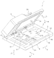
本発明の実施形態に係る画像読取装置1は、原稿Pを載置する載置面3を有する原稿台5と、回動軸7を中心に回動して、原稿台5を覆う閉状態と、原稿台5を開放する開状態とに変位する原稿カバー9と、原稿カバー半開状態検知機構としての、原稿台5の側に配置され、外力Fを受けて開閉状態検知センサーとなる半開状態検知用のスイッチ11(図7等参照)を押圧する押圧部13と、原稿カバー9の側に配置され、押圧部13に対して外力Fを付与可能な位置に回動可能に設けられた回動レバー15と、該回動レバー15の一端17(図4等参照)側を原稿カバー9から遠ざかる方向Rに付勢力を付与する付勢部材19(図6等参照)と、を備えることによって基本的に構成されている。
(1) Outline of the overall configuration of the image reader (see FIGS. 1 to 3)
The
そして、原稿カバー9が前記開状態から前記閉状態に変位する過程で所定の角度θ(一例として20°±5°、好ましくは18°)になった際に、回動レバー15の一端17が、押圧部13に外力F(図8等参照)を作用させて該押圧部13を押し下げてスイッチ11の状態(例えばON状態とOFF状態)を変化させる。前記所定の角度θから、前記閉状態に変位する過程においては、回動レバー15の一端17が、前記付勢力に抗して原稿カバー9に近づく方向Cに回動しながら、継続して押圧部13を押し下げてスイッチ11の前記状態を維持するようになっている。
Then, when the
また、図示の実施形態では、開閉状態検知センサーとして閉状態を検知する一例として機械式接点センサーによって構成されるセンサー21が前記原稿台5の表面における前後方向Hの装置前面側の先端23側の位置に設けられている。
更に、原稿台5の載置面3を形成する透過ガラス等の下方には、一例として光センサーによって構成される7個の原稿サイズ検知センサー27A、27B、27C、27D、27E、27F、27Gを備えることによって構成されるサイズ検知機構25が設けられている。そして、これら7個の原稿サイズ検知センサー27A〜27Gの検知結果の組み合わせによって原稿台5の載置面3にセットされた原稿Pの向きとサイズが検知されるようになっている。
Further, in the illustrated embodiment, as an example of detecting the closed state as the open / close state detection sensor, the
Further, under the transparent glass or the like forming the mounting surface 3 of the
この他、本実施形態では、原稿カバー9に対して自動原稿送り装置(ADF)29と原稿抑えマット31が設けられており、原稿台5の載置面3における左右方向Vの左端近傍には載置面3にセットされた原稿Pの内容を読み取る読取部33が設けられている。
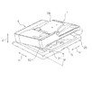
尚、以下の説明では図1に表す原稿カバー9をいっぱいに開いた状態を全開状態、該全開状態から図2に表す半開状態での検知を開始する前までの状態を開状態、図2に表す状態から図3に表す状態に至る前までの状態を半開状態、図3に表す原稿カバー9を完全に閉めて原稿台5の載置面3を塞いだ状態を閉状態または全閉状態と便宜上定義して説明する。
In addition, in the present embodiment, an automatic document feeder (ADF) 29 and a
In the following description, the state in which the
また、原稿台5の載置面3の左右方向をV、前後方向をHとし、載置面3の左後方のコーナー部を、原稿Pをセットする際の基準となる基準点Oとする。更に、左右方向Vの基準点O側の端部を読取開始端V1、反対側の端部を読取終了端V2とし、前後方向Hの基準点O側の端部を読取開始端H1、反対側の端部を読取り終了端H2と定義する。
Further, the left-right direction of the mounting surface 3 of the
(2)回動レバー及び押圧部周辺の構成(図4から図11参照)
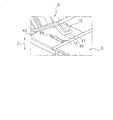
図7に表すように、原稿カバー9にはカバー側開口35が設けられている。回動レバー15は、他端18がカバー側開口35内に位置し、回動レバー15の一端17は付勢部材19の付勢力によりカバー側開口35外に突出し、回動レバー15の他端18側を支点として回動するように構成されている。
具体的には、図9に表すように、原稿カバー9を閉状態にしたとき、原稿台5の載置面3と対向する下面の回動軸7寄りの位置に回動レバー15を収容できる大きさの所定深さのカバー側開口35が設けられている。このカバー側開口35の回動軸7寄りの奥部に回動軸37が水平に架け渡されている。
(2) Configuration around the rotating lever and pressing portion (see FIGS. 4 to 11)
As shown in FIG. 7, the
Specifically, as shown in FIG. 9, when the
回動軸37には、図11に表すように、他端18が二股に分れて軸受39、39を構成し、軸受39、39から一端17にかけて延びるレバー本体41と、一端17に図5及び図8に表す半開状態に到達した状態で原稿台5の載置面3における読取開始端H1の外方に延長形成されている支持板部45の上面とほぼ平行になるように斜めにカットされた当接面43を有する回動レバー15が装着されている。
また、一方の軸受39の外周には一例として捩りコイルばねによって構成される付勢部材19のコイル部が外嵌されている。この捩りコイルばねの一端を回動レバー15に係止し、他端を原稿カバー9のカバー側開口35を形成している部材の適宜の部位に係止することで回動レバー15が常時、原稿カバー9から遠ざかる方向R(図1、図7)に突出しようとする付勢力を付与している。
As shown in FIG. 11, the
Further, as an example, a coil portion of an urging
また、原稿カバー9が図6及び図9に表す閉状態のときは、回動レバー15は一端17側の少なくとも一部が押圧部13に接して押し下げた状態で前記付勢力に抗してカバー側開口35内に収納されるように構成されている。
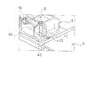
押圧部13は支持板部45の回動軸7側に設けられる揺動軸51を支点として揺動自由端53揺動する湾曲した翼板状の部材であり、該押圧部13の揺動軸基部57がスイッチ11の状態を変化させる作用点になっている。
Further, when the
The
そして、図9及び図10に表すように、原稿カバー9が閉状態のときは、回動レバー15の一端17に形成されている当接面43の一部が押圧部13の湾曲した上面の一部に当接して、該押圧部13を下方に押し下げると共に、当接面43が支持板部45の上面に当接することで回動レバー15を収容方向Cに回動させるため、その回動量に応じた量がカバー側開口35内に収納される。
Then, as shown in FIGS. 9 and 10, when the
(3)原稿カバーの開閉状態と回動レバーの動きとスイッチの状態変化の関係(図4から図9参照)
次に、原稿カバー9の開閉状態を(A)開状態、(B)半開状態、(C)閉状態、の3段階に分け、これらの各開閉状態に対応した回動レバー15の動きと押圧部13を介して実行されるスイッチ11の状態変化の関係を具体的に説明する。
(A)開状態(図4及び図7参照)
原稿カバー9が開状態のときは、回動レバー15の一端17側は付勢部材19の付勢力によって突出方向Rいっぱいに回動した状態になっている。また、回動レバー15の一端17は、支持板部45に形成されている原稿台側開口55から上方に突出している押圧部13の上面に対し離間した上方位置に位置しており、スイッチ11の状態は変化していない(一例としてOFF状態である)。
(3) Relationship between the open / closed state of the document cover, the movement of the rotary lever, and the state change of the switch (see FIGS. 4 to 9).
Next, the open / closed state of the
(A) Open state (see FIGS. 4 and 7)
When the
スイッチ11は本実施形態では上下方向Zにおいて原稿台5の支持板部45の表面より下方に配置されており、該スイッチ11に作用する揺動軸基部57を有する押圧部13における回動レバー15の一端17の当接面43と接触する部位だけが原稿台側開口55から原稿カバー9側に突出している。
そして、回動レバー15の当接面43が押圧部13に当接していない本状態では、押圧部13は上限位置に位置しており、スイッチ11の状態に変位をもたらせない(一例としてOFF状態のままである)。
In the present embodiment, the
In this state where the
(B)半開状態(図5及び図8参照)
原稿カバー9が閉方向に回動して半開状態に至ると、回動レバー15の一端17に設けられている当接面43が、支持板部45の表面とほぼ平行になり、該当接面43の一部が押圧部13の上面の適宜の位置に当接して該押圧部13を、揺動軸51を支点として揺動自由端53側を下方に変位させる方向に揺動させる。
これにより、スイッチ11は揺動軸基部57から下方に押し下げる方向の外力Fを受けるようになって、状態が変化する(一例としてON状態になる)。一方、この時の回動レバー15の位置(角度)は前記(A)の開状態と同じである。即ち、回動レバー15の一端17側は付勢部材19の付勢力によって突出方向Rいっぱいに回動した状態になっている。
(B) Half-open state (see FIGS. 5 and 8)
When the
As a result, the
(C)閉状態(図6及び図9参照)
原稿カバー9が更に閉方向に回動して閉状態に至ると、回動レバー15の一端17に形成されている当接面43が支持板部45の表面に当接することにより、これ以上の下方への移動が規制される。
これにより、回動レバー15は回動軸37を支点として付勢部材19の付勢力に抗して収容方向Cに回動するようになり、カバー側開口35の内部にその回動角度に応じた所定の量が収納されて行く。
(C) Closed state (see FIGS. 6 and 9)
When the
As a result, the rotating
一方、回動レバー15の一端17に形成されている当接面43はカバー側開口35の周囲における支持板部45の表面に接した状態で、滑りながら水平に当接支持板部45の基端部に向けて移動する。
このときの押圧部13の揺動角度は前記(B)の半開状態と同じであり、スイッチ11は前記変化した状態(一例としてON状態)をそのまま維持している。これにより、スイッチ11の状態を元に戻す(一例としてOFF状態にする)押込み不足やスイッチ11に破損をもたらす押込み過ぎ等の不具合の発生を低減し得るようになっている。
On the other hand, the
The swing angle of the
(4)原稿の有無、原稿カバーの開閉状態及び原稿サイズの検知処理の内容(図12から図20参照)
本実施形態では前述したように原稿台5に載置された原稿Pのサイズを検知するサイズ検知機構25を備えており、原稿カバー9が前記開状態から前記閉状態に変位する過程でスイッチ11の状態が変化したことをトリガーとしてサイズ検知機構25を作動させるように構成されている。
以下、本発明の実施形態に係る画像読取装置1を使用することによって実行される原稿Pの有無の判定及び原稿カバー9の開閉状態の検知から原稿Pのサイズの検出までの検知処理の内容の一例を図12から図20に基づいて具体的に説明する。
(4) Presence / absence of original, open / closed state of original cover, and content of original size detection processing (see FIGS. 12 to 20)
In the present embodiment, as described above, the
Hereinafter, the contents of the detection process from the determination of the presence / absence of the document P and the detection of the open / closed state of the
(A)原稿サイズ検知処理の流れの概念(図12参照)
ここで行う原稿サイズ検知処理は、原稿Pの読取時の原稿サイズを自動判定し、ユーザー操作を簡便にする処理である。そして、原稿サイズは、原稿台5の左右方向Vの読取開始端V1の近傍において前後方向Hに適宜の間隔を開けて配置される5個の原稿サイズ検知センサー27A、27B、27C、27D、27Eと、読取開始端V1から適宜の間隔を開けるとともに、左右方向V、前後方向Hのそれぞれが異なる位置に配置される2個の原稿サイズ検知センサー27F、27Gと、の計7個の原稿サイズ検知センサー27の検知出力により判定される。
(A) Concept of flow of document size detection processing (see FIG. 12)
The document size detection process performed here is a process that automatically determines the document size at the time of scanning the document P and simplifies the user operation. The document size is determined by five document
即ち、原稿Pが原稿台5にセットされる際の原稿カバー9の開閉状態をスイッチ11とセンサー21とによって検知し、半開状態と閉状態に2つの状態で7個の原稿サイズ検知センサー27の検知出力から、各原稿サイズ検知センサー27の位置での原稿Pの有無と原稿サイズ検知センサー27の故障の有無とを判別して原稿Pのサイズを特定する。
原稿サイズ検知処理は、原稿カバー9の全開状態の検出によりスタートするが、画像読取中、画像読取中にエラーが発生した時、自動原稿送り装置(ADF)29の使用中、自動原稿送り中にエラーが発生した時は原稿サイズ検知処理を実施しない。
That is, the open / closed state of the
The document size detection process is started by detecting the fully open state of the
具体的には以下の流れで原稿Pのサイズ検知処理が実施される。先ず、図12中のステップS1により原稿カバー9の全開状態の検出によりユーザーによる原稿Pのセットの開始が認識される。次に、ステップS2に移行し、原稿カバー9の半開状態の検出(原稿カバー半開状態検知機構のスイッチ11による)によりユーザーによる原稿Pのセットの終了と閉動作の開始が認識される。
次に、ステップS3に移行して原稿カバー9の半開状態において原稿サイズの1回目の検知出力が取得される。次に、ステップS4に移行して原稿カバー9の閉状態の検出(閉状態検知用のセンサー21による)によりユーザーによる閉動作の終了が認識される。
Specifically, the size detection process of the document P is performed according to the following flow. First, in step S1 in FIG. 12, the user recognizes the start of setting the document P by detecting the fully open state of the
Next, the process proceeds to step S3, and the first detection output of the document size is acquired in the half-open state of the
次に、ステップS5に移行して原稿カバー9の閉状態において原稿サイズの2回目の検知出力が取得される。次に、ステップS6に移行して2回の出力結果から原稿サイズ検知センサー27が配置されている7個所での原稿Pの有無及び原稿サイズ検知センサー27の故障の判定が判断される。
次に、ステップS7に移行して前記判断結果を判定テーブルと比較して原稿Pのサイズを判定する。
Next, the process proceeds to step S5, and the second detection output of the document size is acquired in the closed state of the
Next, the process proceeds to step S7, and the determination result is compared with the determination table to determine the size of the document P.
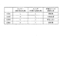
(B)原稿カバーの開閉状態と開閉状態検知センサーの出力との関係(図13参照)
原稿カバー9の開閉状態は、半開状態検知用のスイッチ11と閉状態検知用のセンサー21の2つの開閉状態検知センサーの出力により検知される。
各センサー11、21の出力と原稿カバー9の開閉状態の関係は図13に表す通りである。即ち、状態1はセンサー21の出力信号がL(例えばON状態)でスイッチ11の出力信号もL(例えばON状態)の場合で、この場合は原稿カバー9が閉状態であると検知される。
(B) Relationship between the open / closed state of the document cover and the output of the open / closed state detection sensor (see FIG. 13)
The open / closed state of the
The relationship between the outputs of the
状態2はセンサー21の出力信号がH(例えばOFF状態)でスイッチ11の出力信号がL(例えばON状態)の場合で、この場合は半開状態と検知される。状態3はセンサー21の出力信号がL(例えばON状態)でスイッチ11の出力信号がH(例えばOFF状態)の場合で、実際は存在しないが動作上は開状態として扱う。
状態4はセンサー21の出力信号がH(例えばOFF状態)でスイッチ11の出力信号もH(例えばOFF状態)の場合で、この場合は開状態と検知される。
The state 2 is a case where the output signal of the
State 4 is a case where the output signal of the
(C)開閉状態検知センサーの故障状態と故障信号の関係(図14参照)
閉状態検知用のセンサー21と半開状態検知用のスイッチ11は、それぞれ独立して故障する場合がある。これらの故障状態を図14に表すように分類し、それぞれの故障状態で原稿カバー9の開閉状態の判定以外の対応、即ち故障しても問題がない対応を行う。従って、これらのセンサー21とスイッチ11に故障が発生した場合でもハードエラーとはしない。
具体的には、これらのセンサー21とスイッチ11が出力信号L(例えばON状態)の状態で故障した場合には故障記号Err−Lを出力して処理を行う。これらのセンサー21とスイッチ11が出力信号H(例えばOFF状態)の状態で故障した場合には故障記号Err−Hを出力して処理を行う。そして、これらのセンサー21とスイッチ11が正常に動作している場合には故障記号Normalを出力して処理を行う。
(C) Relationship between the failure state of the open / close state detection sensor and the failure signal (see FIG. 14)
The
Specifically, when these
(D)開閉状態検知センサーの故障状態と各状態での対応(図15参照)
閉状態検知用のセンサー21と半開状態検知用のスイッチ11から故障記号が出力された場合には、図15に表す対応をとる。具体的には、センサー21がNormalでスイッチ11もNormalの場合には両方とも正常であるから、正常に動作し、次に説明する原稿サイズ検知処理シーケンスに移行する。また、センサー21がNormalでスイッチ11がErr−Lの場合には開状態(図13中の状態4)と認識しないため、原稿サイズ検知処理シーケンスに移行しない。
センサー21がNormalでスイッチ11がErr−Hの場合には開状態(図13中の状態4)と認識し原稿サイズ検知処理シーケンスに移行するが、それ以降の半開状態(図13中の状態2)を認識しないため、それ以降の処理を行わない。また、センサー21がErr−Lでスイッチ11がNormalの場合には開状態(図13中の状態4)と認識しないため、原稿サイズ検知処理シーケンスに移行しない。
(D) Failure status of open / close status detection sensor and response in each status (see Fig. 15)
When a failure symbol is output from the closed
When the
センサー21がErr−Lでスイッチ11もErr−Lの場合には開状態(図13中の状態4)と認識しないため、原稿サイズ検知処理シーケンスに移行しない。また、センサー21がErr−Lでスイッチ11がErr-Hの場合には開状態(図13中の状態4)と認識しないため、原稿サイズ検知処理シーケンスに移行しない。
センサー21がErr−Hでスイッチ11がNormalの場合には、開状態(図13中の状態4)を認識するため原稿サイズ検知処理シーケンスに移行し、半開状態(図13中の状態2)も認識するためそのまま処理を行い、閉状態(図13中の状態1)を認識しないため、それ以降の処理を行わない。
When the
When the
センサー21がErr−Hでスイッチ11がErr−Lの場合には開状態(図13中の状態4)と認識しないため、原稿サイズ検知処理シーケンスに移行しない。
また、センサー21がErr−Hでスイッチ11もErr−Hの場合には開状態(図13中の状態4)のままのため、原稿サイズ検知処理シーケンスに移行しない。
When the
Further, when the
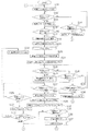
(E)原稿サイズ検知処理シーケンスの流れ(図16参照)
以下のシーケンスを実行する場合の留意点ないし予備処理として以下の処理が行われる。先ず、電源ON時、及び低電力移行時は原稿Pのサイズは不定状態として処理を行う。また、原稿カバー9が開状態のときと原稿カバー9が半開状態のときは低電力に移行しない。
また、読み取り等の別シーケンスが呼び出されたら、本シーケンスを抜け出して別シーケンスに移行する。以下、図16に基づいて原稿サイズ検知処理シーケンスの流れを具体的に説明する。
(E) Flow of document size detection processing sequence (see FIG. 16)
The following processing is performed as a precaution or preliminary processing when executing the following sequence. First, when the power is turned on and when the power is low, the size of the document P is set to be indefinite. Further, when the
In addition, when another sequence such as reading is called, the present sequence is exited and another sequence is shifted to. Hereinafter, the flow of the document size detection processing sequence will be specifically described with reference to FIG.
先ず、ステップS11で7個の原稿サイズ検知センサー27A〜27GをすべてOFF状態にする。次に、ステップS12に移行して原稿カバー9が開状態であるか否かの判断が行われる。ステップS12で開状態であると判断された場合にはステップS13に移行し原稿Pのサイズを不定状態にセットする。
一方、ステップS12で開状態でないと判断された場合には、ステップS14に移行して原稿カバー9が半開状態か否かの判断が行われる。ステップS14で半開状態であると判断された場合には、ステップS15に移行し原稿Pのサイズを不定状態にセットして前記ステップS11に戻り、ステップS11以降の処理を繰り返し実行する。
First, in step S11, all seven document
On the other hand, if it is determined in step S12 that the
また、ステップS13に移行後はステップS16に移行し、原稿カバー9が半開状態か否かの判断が行われる。ステップS16で半開状態であると判断された場合には、ステップS17に移行し、半開状態監視タイマーの計測を開始する。尚、ステップS16で半開状態でないと判断された場合には、ステップS16に戻り半開状態になるまでステップS16の処理が繰り返し実行される。
ステップS17に移行後はステップS18に移行し、7個の原稿サイズ検知センサー27A〜27GをすべてON状態にする。次にステップS19に移行して10ms待ち、ステップS20に移行して前記7個の原稿サイズ検知センサー27A〜27Gの検知出力を取得し、ステップ22に移行して、取得した7個の検知出力を原稿サイズ検出センサーの1回目の出力として保持する。
Further, after the transition to step S13, the transition to step S16 is performed to determine whether or not the
After the transition to step S17, the transition to step S18 is performed, and all seven document
次に、ステップS22に移行して原稿カバー9が閉状態か否かの判断が行われる。ステップS22で閉状態であると判断された場合には、ステップS23に移行し、閉状態待ちタイマーの計測を開始すると共に半開状態監視タイマーをリセットする。
一方、ステップS22で閉状態でないと判断された場合には、ステップS24に移行して原稿カバー9が開状態か否かの判断が行われ、原稿カバー9が開状態と判断された場合は、更にステップS26に移行して半開状態監視タイマーをリセット後、ステップS11に戻り、ステップS11以降の処理が再度実行される。また、ステップS24で開状態でないと判断された場合には、ステップS25に移行して半開状態監視タイマーが10s経過したか否かの判断が行われ、10s経過したと判断された場合には前記ステップS26に移行して半開状態監視タイマーをリセット後、ステップS11に戻り、10s経過していないと判断された場合にはステップS22に戻り、ステップS22以降の処理が再度実行される。
Next, the process proceeds to step S22, and it is determined whether or not the
On the other hand, if it is determined in step S22 that the
また、ステップS23に移行後はステップS27に移行し、閉状態待ちタイマーが0.5s経過したか否かの判断が行われる。ステップS27で0.5s経過していると判断された場合にはステップS28に移行して閉状態待ちタイマーをリセットする。
一方、ステップS27で0.5s経過していないと判断された場合にはステップS29に移行して、原稿カバー9が閉状態であるか否かの判断が再度実行される。ステップS29で閉状態であると判断された場合にはステップS27に戻ってステップS27以降の処理が再度実行される。
Further, after the transition to step S23, the transition to step S27 is performed, and it is determined whether or not the closed state waiting timer has elapsed 0.5 s. If it is determined in step S27 that 0.5 s has elapsed, the process proceeds to step S28 to reset the closed state wait timer.
On the other hand, if it is determined in step S27 that 0.5 s has not elapsed, the process proceeds to step S29, and the determination as to whether or not the
また、ステップS29で閉状態でないと判断された場合には、ステップS30に移行して閉状態待ちタイマーをリセット後、ステップS31に移行して原稿カバー9が開状態か半開状態かの判断が行われる。
ステップS31で開状態と判断された場合にはステップS11に戻り、ステップS11以降の処理が再度実行される。一方、ステップS31で半開状態と判断された場合には、ステップS32に移行して半開状態監視タイマーの計測を開始し、ステップS22に戻りステップS22以降の処理が再度実行される。
If it is determined in step S29 that the
If it is determined in step S31 that the state is open, the process returns to step S11, and the processes after step S11 are executed again. On the other hand, when it is determined in step S31 that the half-open state is determined, the process proceeds to step S32 to start the measurement of the half-open state monitoring timer, returns to step S22, and the processes after step S22 are executed again.
また、ステップS27で0.5s経過していると判断して、ステップS28に移行後はステップS33に移行して7個の原稿サイズ検知センサー27A〜27Gの検知出力を取得する。次に、ステップS34に移行して取得した7個の検知出力を原稿サイズ検出センサーの2回目の検知出力として保持する。
次に、ステップS35に移行して、原稿カバー9が閉状態か否かの判断が行われ、閉状態と判断された場合には、ステップS36に移行して次に述べる図17で表す原稿Pの有無判定を行い、更にステップS37に移行して図18で表す原稿Pのサイズ判定を行った後、ステップS11に戻ってステップS11以降の処理が繰り返し実行される。
尚、ステップS35で閉状態でないと判断された場合には、直ちにステップS11に戻り、ステップS11以降の処理が再度実行される。
Further, it is determined in step S27 that 0.5 s has elapsed, and after the transition to step S28, the transition to step S33 is performed to acquire the detection outputs of the seven document
Next, the process proceeds to step S35 to determine whether or not the
If it is determined in step S35 that the state is not closed, the process immediately returns to step S11, and the processes after step S11 are executed again.
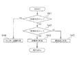
(F)原稿の有無判定の流れ(図17参照)
図16のステップS35で原稿カバー9が閉状態であると判断された場合には図17に表す原稿Pの有無判定が7個の原稿サイズ検知センサー27A〜27Gのすべてに対して実行される。
先ず、ステップS41で図16中のステップS34で保持した原稿サイズ検知センサー27の2回目の検知出力がL(例えばON状態)であるか否かの判断が行われる。ステップS41でL(例えばON状態)と判断された場合にはステップS42に移行して図16中のステップS21で保持した原稿サイズ検知センサー27の1回目の検知出力がL(例えばON状態)であるか否かの判断が行われる。
(F) Flow of determining the presence or absence of a document (see FIG. 17)
When it is determined in step S35 of FIG. 16 that the
First, in step S41, it is determined whether or not the second detection output of the document
ステップS42でL(例えばON状態)と判断された場合にはステップS43に移行して原稿Pが有ると判定され図16中のステップS37に移行し、次に述べる原稿Pのサイズ判定が実行される。
また、ステップS41で原稿サイズ検知センサー27の2回目の検知出力がH(例えばOFF状態)と判断された場合には、ステップS44に移行して7個の原稿サイズ検知センサー27A〜27Gの故障判定を行う。
また、ステップS42で原稿サイズ検知センサー27の1回目の検知出力がH(例えばOFF状態)と判断された場合には、ステップS45に移行して原稿Pが無いと判定される。
If it is determined to be L (for example, in the ON state) in step S42, the process proceeds to step S43, it is determined that there is a document P, the process proceeds to step S37 in FIG. 16, and the size determination of the document P described below is executed. To.
If the second detection output of the document
Further, when the first detection output of the document
(G)原稿のサイズ判定の流れ(図18参照)
図17で表すフローチャートによって原稿Pの有無が判定されると、図16中のステップS37に移行して原稿Pのサイズ判定が実行される。
先ず、ステップS51で7個の原稿サイズ検知センサー27A〜27G中に故障判定されたセンサーが有るか無いかの判断が行われる。ステップS51で故障判定されたセンサーが無いと判断された場合にはステップS52に移行し、各センサー27A〜27Gにおける原稿Pの有無判定の結果が次に述べる図20に表す原稿Pのサイズ判定テーブルと一致したか否かの判断が行われる。
(G) Flow of document size determination (see FIG. 18)
When the presence or absence of the document P is determined by the flowchart shown in FIG. 17, the process proceeds to step S37 in FIG. 16 and the size determination of the document P is executed.
First, in step S51, it is determined whether or not there is a sensor whose failure is determined among the seven document
ステップS52で原稿Pのサイズ判定テーブルと一致したと判断された場合には、ステップS53に移行して一致した原稿Pのサイズをセットされた原稿Pのサイズと判定する。
一方、ステップS51で故障判定されたセンサー27が有ると判断された場合と、ステップS52で原稿Pのサイズ判定テーブルと一致しないと判断された場合には、ステップS54に移行して原稿Pのサイズ検出が不可であると判定する。
If it is determined in step S52 that the size of the original P matches the size determination table of the original P, the process proceeds to step S53 and the size of the matched original P is determined to be the size of the set original P.
On the other hand, when it is determined that there is a
(H)原稿サイズと原稿サイズ検知センサーとの位置関係と、各原稿サイズ検知センサーによる原稿の有無検出結果に基づく原稿サイズの判定(図19及び図20参照)
本実施形態では、載置面3の左右方向Vの読取開始端V1に沿う位置に基準点Oに近い方から27A、27B、27C、27D、27Eの順で5個の原稿サイズ検知センサーが配置されている。また、これら5個の原稿サイズ検知センサー27A〜27Eから左右方向Vに離間し、左右方向V、前後方向Hのそれぞれが異なる位置に2個の原稿サイズ検知センサー27F、27Gが配置されている。
また、図中、A6Vで示す原稿PはA6サイズ縦向きでセットされた原稿Pを意味し、A6Hで示す原稿PはA6サイズ縦向きでセットされた原稿Pを意味し、A6Hで示す原稿PはA6サイズ横向きでセットされた原稿Pを意味している。同様にA5〜A3、B6〜B4の各サイズの原稿Pも、縦向きでセットされたものは末尾に「V」を付け、横向きでセットされたものは末尾に「H」を付けてこれらを識別している。
(H) Judgment of the original size based on the positional relationship between the original size and the original size detection sensor and the presence / absence detection result of the original by each original size detection sensor (see FIGS. 19 and 20).
In the present embodiment, 27A from the side closer to the reference point O to the position along the reading start end V1 of the right and left direction V of the mounting
Further, in the figure, the original P indicated by A6V means the original P set in A6 size portrait orientation, the original P indicated by A6H means the original P set in A6 size portrait orientation, and the original P indicated by A6H. Means the original P set in A6 size landscape orientation. Similarly, for the originals P of each size of A5 to A3 and B6 to B4, those set in portrait orientation have a "V" at the end, and those set in landscape orientation have an "H" at the end. I'm identifying.
そして、本実施形態では従来、図19中、仮想線で表す位置に配置されていた原稿サイズ検知センサー27Fの位置を実線で示す位置に移動しており、これにより従来識別できなかったA5Vの原稿Pを識別できるようにしている。
このような配置の7個の原稿サイズ検知センサー27A〜27Gによって判定できる原稿Pのサイズは図20に表すサイズ判定テーブルの通りであり、A5サイズ、B5サイズ、A4サイズの原稿Pについては縦向きと横向きの両方、B4サイズとA3サイズの原稿Pについては、それぞれ縦向きの識別ができるようになっている。また、これより小さなB6サイズの原稿Pについても横向きについては識別でき、B6サイズの縦向きとA6サイズに縦向きと横向きの原稿Pについては原稿Pの有無の識別ができるように構成されている。
Then, in the present embodiment, the position of the document
The size of the document P that can be determined by the seven document
そして、このようにして構成される本実施形態に係る画像読取装置1によれば、従来走査ごとや装置ごとに検出結果にバラ付きが大きかった半開状態での原稿Pの有無の検知精度を高価な加速度センサーや透過型の光学センサー等を用いることなく安価でコンパクトな構造によって向上させることが可能になる。
また、半開状態検知用のセンサーとして機械式の接点センサーであるスイッチ11を使用することで不浄空気等の環境の影響を受けにくくすることが可能になる。更に、前述した構成の回動レバー15と、押圧部13と、カバー側開口35と、原稿台側開口55を備えた支持板部45と、付勢部材19と、を採用したことにより、原稿カバー9が半開状態から閉状態に移行する過程で回動レバー15の一端17の当接面43が水平にスライドするため、スイッチ11の押し不足や押し過ぎによる不具合の発生を低減させることができる。
Then, according to the
Further, by using the
[他の実施の形態]
本発明に係る画像読取装置1は、以上述べたような構成を有することを基本とするものであるが、本願発明の要旨を逸脱しない範囲での部分的構成の変更や省略等を行うことも勿論可能である。
例えば前記実施形態で述べた構成を一般化した処理装置に適用することが可能である。この場合には該処理装置は画像読取装置1の原稿台5に対応する本体部と、画像読取装置1の原稿カバー9に対応する開閉カバーと、画像読取装置1と同様に押圧部13と、回動レバー15と、付勢部材19と、を基本的に備えた処理装置が採用できる。
[Other embodiments]
The
For example, the configuration described in the above embodiment can be applied to a generalized processing apparatus. In this case, the processing device includes a main body portion corresponding to the
そして、このようにして構成される処理装置によれば、開閉カバーが開状態から閉状態に変位する過程で所定の角度θとなった際に、回動レバー15の一端17が、押圧部13に外力Fを作用させて押圧部13を押し下げてスイッチ11の状態を変化させ、所定の角度θから閉状態に変位する過程においては、回動レバー15の一端17が前記付勢力に抗して開閉カバーに近づく方向Cに回動しながら、押圧部13を押し下げてスイッチ11の状態(例えばON状態)を維持し得るようになる。
Then, according to the processing device configured in this way, when the opening / closing cover reaches a predetermined angle θ in the process of being displaced from the open state to the closed state, one
また、本発明の画像読取装置1は、画像読取装置1単体で製品化されている専用機だけでなく、記録装置、ファクシミリ、複写機等と組み合わされた複合機に適用することも可能である。また、回動レバー15を原稿カバー9に対して取り付ける向きを逆にして原稿カバー9の回動軸7側に回動レバー15の一端17が向くように配置してもよい。
Further, the
この他、半開状態での検知処理を行う時の原稿カバー9の角度θは、前述した実施形態の説明の中で述べた角度θに限らず種々の角度が採用でき、光路を変えるミラー等の組み合わせにより更に大きな角度θでも所望の検出精度が得られる場合には、更に大きな角度θに設定することが可能である。
また、原稿カバー9は自動原稿送り装置(ADF)を有しない単なる蓋体としての機能のみを有するものであっても構わない。
In addition, the angle θ of the
Further, the
1…画像読取装置、3…載置面、5…原稿台、7…回動軸、9…原稿カバー、
11…スイッチ(半開状態検知用)、13…押圧部、15…回動レバー、17…一端、
18…他端、19…付勢部材、21…センサー(閉状態検知用)、23…先端、
25…サイズ検知機構、27…原稿サイズ検知センサー、
29…自動原稿送り装置(ADF)、31…原稿抑えマット、33…読取部、
35…カバー側開口、37…回動軸、39…軸受、41…レバー本体、43…当接面、
45…支持板部、51…揺動軸、53…揺動自由端、55…原稿台側開口、
57…揺動軸基部、P…原稿、F…外力、R…遠ざかる方向(突出方向)、
C…近づく方向(収容方向)θ…角度、H…前後方向、V…左右方向、O…基準点、
V1…読取開始端、V2…読取終了端、H1…読取開始端、H2…読取終了端、
Z…上下方向
1 ... Image reader, 3 ... Mounting surface, 5 ... Document stand, 7 ... Rotating axis, 9 ... Document cover,
11 ... Switch (for half-open state detection), 13 ... Pressing part, 15 ... Rotating lever, 17 ... One end,
18 ... other end, 19 ... urging member, 21 ... sensor (for detecting closed state), 23 ... tip,
25 ... size detection mechanism, 27 ... document size detection sensor,
29 ... Automatic document feeder (ADF), 31 ... Document holding mat, 33 ... Reader,
35 ... Cover side opening, 37 ... Rotating shaft, 39 ... Bearing, 41 ... Lever body, 43 ... Contact surface,
45 ... Support plate, 51 ... Shaking shaft, 53 ... Swinging free end, 55 ... Document stand side opening,
57 ... Shaking shaft base, P ... Original, F ... External force, R ... Moving away direction (protruding direction),
C ... Approaching direction (accommodation direction) θ ... Angle, H ... Front-back direction, V ... Left-right direction, O ... Reference point,
V1 ... reading start end, V2 ... reading end end, H1 ... reading start end, H2 ... reading end end,
Z ... Vertical direction
Claims (6)
回動軸を中心に回動して、前記原稿台を覆う閉状態と、前記原稿台を開放する開状態とに変位する原稿カバーと、
前記原稿台の側に配置され、外力を受けてスイッチを押圧する押圧部と、
前記原稿カバーの側に配置され、前記押圧部に対して前記外力を付与可能な位置に回動可能に設けられた回動レバーと、
前記回動レバーの一端側を前記原稿カバーから遠ざかる方向に付勢力を付与する付勢部材と、を備え、
前記原稿カバーが前記開状態から前記閉状態に変位する過程で所定の角度となった際に、前記回動レバーの一端が、前記押圧部に前記外力を作用させて該押圧部を押し下げて前記スイッチの状態を変化させ、
前記所定の角度から、前記閉状態に変位する過程においては、前記回動レバーの一端が、前記付勢力に抗して前記原稿カバーに近づく方向に回動しながら、前記押圧部を押し下げて前記スイッチの前記状態を維持する、ことを特徴とする画像読取装置。 A platen with a mounting surface on which the manuscript is placed,
A document cover that rotates about a rotation axis and is displaced to a closed state that covers the platen and an open state that opens the platen.
A pressing part that is placed on the side of the platen and presses the switch by receiving an external force,
A rotating lever arranged on the side of the document cover and rotatably provided at a position where the external force can be applied to the pressing portion.
An urging member that applies urging force to one end side of the rotating lever in a direction away from the document cover is provided.
When the document cover reaches a predetermined angle in the process of being displaced from the open state to the closed state, one end of the rotating lever exerts the external force on the pressing portion to push down the pressing portion. Change the state of the switch,
In the process of displacing from the predetermined angle to the closed state, one end of the rotating lever pushes down the pressing portion while rotating in a direction approaching the document cover against the urging force. An image reader, characterized in that the state of the switch is maintained.
前記原稿カバーにはカバー側開口が設けられ、
前記回動レバーは、他端が前記カバー側開口内に位置し、前記一端は前記付勢力により前記カバー側開口外に突出し、前記他端側を支点として回動する、ことを特徴とする画像読取装置。 In the image reading apparatus according to claim 1,
The document cover is provided with an opening on the cover side.
The image of the rotating lever is characterized in that the other end is located in the cover side opening, the one end projects out of the cover side opening by the urging force, and the other end rotates with the other end side as a fulcrum. Reader.
前記原稿カバーが前記閉状態のときは、前記回動レバーは前記一端側の少なくとも一部が前記押圧部に接した状態で前記付勢力に抗して前記カバー側開口内に収納される、ことを特徴とする画像読取装置。 In the image reading apparatus according to claim 2,
When the document cover is in the closed state, the rotating lever is housed in the cover-side opening against the urging force with at least a part of the one end side in contact with the pressing portion. An image reader characterized by.
前記スイッチは上下方向において前記原稿台の表面より下方に配置され、
前記押圧部の前記回動レバーと接触する部位が前記原稿台に形成された原稿台側開口から前記原稿カバー側に突出している、ことを特徴とする画像読取装置。 In the image reading apparatus according to any one of claims 1 to 3,
The switch is arranged below the surface of the platen in the vertical direction.
An image reading device, wherein a portion of the pressing portion that comes into contact with the rotating lever projects from an opening on the platen side formed in the platen toward the document cover side.
原稿台に載置された原稿のサイズを検知するサイズ検知機構を備え、
前記原稿カバーが前記開状態から前記閉状態に変位する過程で前記スイッチの状態が変化したことをトリガーとして前記サイズ検知機構を作動させる、ことを特徴とする画像読取装置。 In the image reading apparatus according to any one of claims 1 to 4.
Equipped with a size detection mechanism that detects the size of the document placed on the platen
An image reading device characterized in that the size detection mechanism is activated by a change in the state of the switch in the process of displacement of the document cover from the open state to the closed state.
回動軸を中心に回動して、前記本体部の一面を覆う閉状態と、前記本体部の一面を開放する開状態とに変位する開閉カバーと、
前記本体部の側に配置され、外力を受けてスイッチを押圧する押圧部と、
前記開閉カバーの側に配置され、前記押圧部に対して前記外力を付与可能な位置に回動可能に設けられた回動レバーと、
前記回動レバーの一端側を前記開閉カバーから遠ざかる方向に付勢力を付与する付勢部材と、を備え、
前記開閉カバーが前記開状態から前記閉状態に変位する過程で所定の角度となった際に、前記回動レバーの一端が、前記押圧部に前記外力を作用させて該押圧部を押し下げて前記スイッチの状態を変化させ、
前記所定の角度から、前記閉状態に変位する過程においては、前記回動レバーの一端が、前記付勢力に抗して前記開閉カバーに近づく方向に回動しながら、前記押圧部を押し下げて前記スイッチの前記状態を維持することを特徴とする処理装置。 With the main body
An opening / closing cover that rotates around a rotation shaft and is displaced into a closed state that covers one surface of the main body and an open state that opens one surface of the main body.
A pressing unit that is placed on the side of the main body and presses the switch by receiving an external force,
A rotating lever arranged on the side of the opening / closing cover and rotatably provided at a position where the external force can be applied to the pressing portion.
An urging member that applies urging force to one end side of the rotating lever in a direction away from the opening / closing cover is provided.
When the opening / closing cover reaches a predetermined angle in the process of being displaced from the open state to the closed state, one end of the rotating lever exerts the external force on the pressing portion to push down the pressing portion. Change the state of the switch,
In the process of displacing from the predetermined angle to the closed state, one end of the rotating lever pushes down the pressing portion while rotating in a direction approaching the opening / closing cover against the urging force. A processing device characterized by maintaining the above-mentioned state of the switch.
Priority Applications (2)
| Application Number | Priority Date | Filing Date | Title |
|---|---|---|---|
| JP2017010447A JP6777883B2 (en) | 2017-01-24 | 2017-01-24 | Image reader and processing device |
| US15/868,268 US10334131B2 (en) | 2017-01-24 | 2018-01-11 | Image reading apparatus and processing device with specific assembly for cover open/close determination |
Applications Claiming Priority (1)
| Application Number | Priority Date | Filing Date | Title |
|---|---|---|---|
| JP2017010447A JP6777883B2 (en) | 2017-01-24 | 2017-01-24 | Image reader and processing device |
Publications (3)
| Publication Number | Publication Date |
|---|---|
| JP2018121161A JP2018121161A (en) | 2018-08-02 |
| JP2018121161A5 JP2018121161A5 (en) | 2020-01-16 |
| JP6777883B2 true JP6777883B2 (en) | 2020-10-28 |
Family
ID=62906688
Family Applications (1)
| Application Number | Title | Priority Date | Filing Date |
|---|---|---|---|
| JP2017010447A Active JP6777883B2 (en) | 2017-01-24 | 2017-01-24 | Image reader and processing device |
Country Status (2)
| Country | Link |
|---|---|
| US (1) | US10334131B2 (en) |
| JP (1) | JP6777883B2 (en) |
Families Citing this family (1)
| Publication number | Priority date | Publication date | Assignee | Title |
|---|---|---|---|---|
| JP2020010153A (en) * | 2018-07-06 | 2020-01-16 | 富士ゼロックス株式会社 | Image reading device and image formation device |
Family Cites Families (11)
| Publication number | Priority date | Publication date | Assignee | Title |
|---|---|---|---|---|
| JP2610431B2 (en) * | 1987-05-13 | 1997-05-14 | 三田工業株式会社 | Image processing device |
| JP3774100B2 (en) | 2000-03-10 | 2006-05-10 | 桂川電機株式会社 | Document size detection method and apparatus |
| JP2008176058A (en) * | 2007-01-18 | 2008-07-31 | Sharp Corp | Document reader |
| JP5197289B2 (en) * | 2008-10-08 | 2013-05-15 | キヤノン株式会社 | Image reading apparatus and image reading and recording apparatus |
| JP5158518B2 (en) | 2009-02-24 | 2013-03-06 | 株式会社リコー | Image processing apparatus, document size detection timing determination method, and program |
| JP5683623B2 (en) * | 2012-04-05 | 2015-03-11 | 株式会社東芝 | Image reading device |
| JP2014103615A (en) * | 2012-11-22 | 2014-06-05 | Brother Ind Ltd | Image reader |
| JP6268894B2 (en) | 2013-10-09 | 2018-01-31 | セイコーエプソン株式会社 | Image reading device |
| JP6167835B2 (en) | 2013-10-15 | 2017-07-26 | セイコーエプソン株式会社 | Image reading device |
| JP2016119571A (en) | 2014-12-19 | 2016-06-30 | 株式会社リコー | Image reading device |
| US10498913B2 (en) * | 2016-07-29 | 2019-12-03 | Canon Kabushiki Kaisha | Image forming apparatus |
-
2017
- 2017-01-24 JP JP2017010447A patent/JP6777883B2/en active Active
-
2018
- 2018-01-11 US US15/868,268 patent/US10334131B2/en active Active
Also Published As
| Publication number | Publication date |
|---|---|
| US10334131B2 (en) | 2019-06-25 |
| JP2018121161A (en) | 2018-08-02 |
| US20180213099A1 (en) | 2018-07-26 |
Similar Documents
| Publication | Publication Date | Title |
|---|---|---|
| JP6204248B2 (en) | Operation panel support mechanism and image forming apparatus having the same | |
| JP6184392B2 (en) | Image reading apparatus and image forming apparatus | |
| JP6777883B2 (en) | Image reader and processing device | |
| JP4921062B2 (en) | Image reading device | |
| US10230859B2 (en) | Multifunction device including lock mechanism that shifts between states of restricting and allowing pivoting between adjacent unit and scanner | |
| US10638005B2 (en) | Scanner and multifunction device | |
| JP4124221B2 (en) | Opening / closing mechanism and image processing apparatus | |
| JP3841211B2 (en) | Hinge and image input / output device using the same | |
| JP6809092B2 (en) | Image reader | |
| JP5158518B2 (en) | Image processing apparatus, document size detection timing determination method, and program | |
| JP6663208B2 (en) | Hinge | |
| JP6982843B2 (en) | Hinge | |
| JP5212272B2 (en) | Image reading apparatus and image forming apparatus | |
| JP4655559B2 (en) | Image forming apparatus | |
| JP6443076B2 (en) | Image reading apparatus and image forming apparatus | |
| JP4887956B2 (en) | Image forming apparatus | |
| JP2016148815A (en) | Hinge | |
| JP7283725B2 (en) | hinge | |
| JP3721975B2 (en) | Key panel | |
| JP2006154586A (en) | Original reader for image forming apparatus | |
| JPH0114132B2 (en) | ||
| JPH042523Y2 (en) | ||
| JP4140172B2 (en) | Opening / closing state detection mechanism of opening / closing body | |
| JP2021082894A (en) | Image forming apparatus | |
| JP2018157511A (en) | Image reading device |
Legal Events
| Date | Code | Title | Description |
|---|---|---|---|
| A521 | Written amendment |
Free format text: JAPANESE INTERMEDIATE CODE: A523 Effective date: 20191121 |
|
| A621 | Written request for application examination |
Free format text: JAPANESE INTERMEDIATE CODE: A621 Effective date: 20191121 |
|
| A977 | Report on retrieval |
Free format text: JAPANESE INTERMEDIATE CODE: A971007 Effective date: 20200820 |
|
| TRDD | Decision of grant or rejection written | ||
| A01 | Written decision to grant a patent or to grant a registration (utility model) |
Free format text: JAPANESE INTERMEDIATE CODE: A01 Effective date: 20200909 |
|
| A61 | First payment of annual fees (during grant procedure) |
Free format text: JAPANESE INTERMEDIATE CODE: A61 Effective date: 20200922 |
|
| R150 | Certificate of patent or registration of utility model |
Ref document number: 6777883 Country of ref document: JP Free format text: JAPANESE INTERMEDIATE CODE: R150 |