JP6777876B2 - Vehicle seat - Google Patents
Vehicle seat Download PDFInfo
- Publication number
- JP6777876B2 JP6777876B2 JP2019186542A JP2019186542A JP6777876B2 JP 6777876 B2 JP6777876 B2 JP 6777876B2 JP 2019186542 A JP2019186542 A JP 2019186542A JP 2019186542 A JP2019186542 A JP 2019186542A JP 6777876 B2 JP6777876 B2 JP 6777876B2
- Authority
- JP
- Japan
- Prior art keywords
- pressure receiving
- receiving member
- vehicle seat
- vibration unit
- frame
- Prior art date
- Legal status (The legal status is an assumption and is not a legal conclusion. Google has not performed a legal analysis and makes no representation as to the accuracy of the status listed.)
- Active
Links
Images


Description
本発明は、少なくともシートクッションおよびシートバックを備えた車両用などの乗物用シートに関し、特に、シートクッションに着座した乗員に振動を伝達可能とした乗物用シートに関する。 The present invention relates to a vehicle seat provided with at least a seat cushion and a seat back, and more particularly to a vehicle seat capable of transmitting vibration to an occupant seated on the seat cushion.
シートクッションおよびシートバックを備えた乗物用シートとして、シートクッションに着座した乗員にマッサージ用の振動を付与するバイブレータをシートバックに内蔵させた車両用シートが従来一般に知られている(例えば特許文献1参照)。 As a vehicle seat provided with a seat cushion and a seat back, a vehicle seat having a built-in vibrator in the seat back that gives vibration for massage to a occupant seated on the seat cushion is generally known (for example, Patent Document 1). reference).
ここで、特許文献1に記載の車両用シートでは、シートバックの骨格を構成するシートバックフレームに対し、上下の補強フレームが左右に掛け渡され、この上下の補強フレームにクリップなどで枠体が取り付けられ、この枠体にバネ部材を介してバイブレータが保持されている。
Here, in the vehicle seat described in
ところで、特許文献1に記載の乗物用シートにおいては、乗員を支持するのは枠体であるところ、バイブレータ(振動ユニット)はバネ部材を介して枠体に保持されているため、バイブレータの振動は、枠体に伝わるまでの間にバネ部材で吸収される恐れがあり、乗員に対する振動伝達効果が低いことが懸念される。
また、バイブレータを枠体に取り付けるための専用のバネ部材を使用することで、部品点数が多くなるという問題があった。
By the way, in the vehicle seat described in
In addition, there is a problem that the number of parts increases by using a dedicated spring member for attaching the vibrator to the frame body.
また、振動ユニットが周囲の部材に干渉すると、異音が発生したり、乗員に違和感を感じさせることがあるので、振動ユニットが周囲の部材に干渉しにくいようにすることが望まれる。 Further, if the vibration unit interferes with the surrounding members, an abnormal noise may be generated or the occupant may feel a sense of discomfort. Therefore, it is desired to prevent the vibration unit from interfering with the surrounding members.
本発明は、以上のような技術的背景に鑑みてなされたものであり、シートクッションに着座した乗員に所望の振動を効率良く伝達することができる乗物用シートを提供することを課題とする。 The present invention has been made in view of the above technical background, and aims to provide a vehicle seat which has as possible out to efficiently transmit the desired vibrations to an occupant sitting on the seat cushion ..
前述した課題を解決する本発明の乗物用シートは、少なくともシートクッションおよびシートバックを備えた乗物用シートであって、前記乗物用シートは、骨格を構成するフレームと、当該フレームの内側に配置されて乗員を支持する受圧部材であって、左右方向に延びるとともに前記左右方向に直交する直交方向に延びる受圧部材と、前記フレームに前記受圧部材を弾性的に支持する支持ワイヤと、前記フレームおよび前記受圧部材を覆う被覆部材とを有し、前記受圧部材は、前記支持ワイヤと係合する第1保持部を有し、前記受圧部材には、前記第1保持部と前記直交方向で並ぶ振動ユニットが付設されることを特徴とする。 The vehicle seat of the present invention that solves the above-mentioned problems is a vehicle seat provided with at least a seat cushion and a seat back, and the vehicle seat is arranged in a frame constituting a skeleton and inside the frame. A pressure-receiving member that extends in the left-right direction and extends in an orthogonal direction orthogonal to the left-right direction, a support wire that elastically supports the pressure-receiving member on the frame, the frame, and the frame. The pressure receiving member has a covering member that covers the pressure receiving member, the pressure receiving member has a first holding portion that engages with the support wire, and the pressure receiving member has a vibration unit that is aligned with the first holding portion in the orthogonal direction. There characterized in that that will be attached.
本発明に係る乗物用シートでは、乗員からの荷重を受けて乗員を乗物用シート内に沈み込ませるように構成された、乗員からの圧力が十分に加わる受圧部材に振動ユニットを付設させている。そのため、シートクッションに着座した乗員が受圧部材に支持された状態で振動ユニットが作動すると、振動ユニットが発生する振動が、乗員からの荷重を受ける受圧部材の全体に直接伝達され、受圧部材から被覆部材を介して乗員に効率良く伝達される。
なお、本発明の被覆部材には、クッションパッドや、クッションパッドの外側に設けられる表皮、シートの背面側を覆う背面カバーなどが含まれる。
In the vehicle seat according to the present invention, a vibration unit is attached to a pressure receiving member to which a sufficient pressure from the occupant is applied, which is configured to receive a load from the occupant and sink the occupant into the vehicle seat. .. Therefore, when the vibration unit operates while the occupant seated on the seat cushion is supported by the pressure receiving member, the vibration generated by the vibration unit is directly transmitted to the entire pressure receiving member that receives the load from the occupant and is covered from the pressure receiving member. Ru is efficiently transferred to the occupant via the member.
The covering member of the present invention includes a cushion pad, a skin provided on the outside of the cushion pad, a back cover covering the back side of the seat, and the like.
また、前記した構成において、前記第1保持部は、前記受圧部材のうち乗員とは反対側の面に形成されていてもよい。 Further, in the above-described configuration, the first holding portion may be formed on the surface of the pressure receiving member opposite to the occupant .
また、前記した構成において、前記受圧部材は、前記支持ワイヤと係合する第2保持部であって、前記第1保持部の左右方向両側に配置される2つの第2保持部を有し、前記直交方向において、前記第1保持部は、前記第2保持部よりも前記振動ユニットから離れていてもよい。 Further, in the above-described configuration, the pressure receiving member is a second holding portion that engages with the support wire, and has two second holding portions arranged on both sides in the left-right direction of the first holding portion. In the orthogonal direction, the first holding portion may be separated from the vibration unit by the second holding portion .
また、前記した構成において、前記受圧部材は、ビードを有し、前記ビードは、前記直交方向において、前記第1保持部に対して前記振動ユニットと同じ側に配置されていてもよい。 Further, in the above-described configuration, the pressure receiving member may have a bead, and the bead may be arranged on the same side as the vibration unit with respect to the first holding portion in the orthogonal direction .
また、前記した構成において、前記受圧部材は、前記振動ユニットを収容する収容凹部を有し、前記収容凹部の底部は、前記第1保持部よりも乗員から離れた位置に位置していてもよい。 Further, in the above-described configuration, the pressure receiving member may have an accommodating recess for accommodating the vibration unit, and the bottom portion of the accommodating recess may be located at a position farther from the occupant than the first holding portion. ..
また、前記した構成において、前記振動ユニットを前記受圧部材に取り付けるための取付ブラケットと、前記収容凹部を覆うカバープレートと、を備え、前記取付ブラケットおよび前記カバープレートは、前記受圧部材に共締めされていてもよい。
また、前記した構成において、前記受圧部材は、前記第1保持部の左右方向両側に2つの孔を有し、前記振動ユニットは、前記左右方向において、前記2つの孔とは異なる位置に配置されていてもよい。
Further, in the above-described configuration, a mounting bracket for mounting the vibration unit to the pressure receiving member and a cover plate covering the accommodating recess are provided, and the mounting bracket and the cover plate are co-tightened to the pressure receiving member. You may be.
Further, in the above-described configuration, the pressure receiving member has two holes on both sides of the first holding portion in the left-right direction, and the vibration unit is arranged at a position different from the two holes in the left-right direction. You may be.
本発明では、シートクッションに着座した乗員が受圧部材に支持された状態で振動ユニットが作動すると、振動ユニットが発生する振動が直接、受圧部材の全体に伝達され、受圧部材から被覆部材を介して乗員に効率良く伝達される。従って、本発明によれば、振動ユニットが発生する所望の振動をシートクッションに着座した乗員に効率良く伝達することができる。 In the present invention, when the vibration unit operates while the occupant seated on the seat cushion is supported by the pressure receiving member, the vibration generated by the vibration unit is directly transmitted to the entire pressure receiving member, and the vibration generated by the vibration unit is directly transmitted from the pressure receiving member to the entire pressure receiving member via the covering member. It is efficiently transmitted to the occupants. Therefore, according to the present invention, Ru can be efficiently transmitted to the desired vibration the vibration unit to generate the occupant seated on the seat cushion.
以下、添付の図面を参照しながら本発明に係る乗物用シートの一実施形態について説明する。一実施形態の乗物用シートは、例えば図1に示すように、自動車の運転席に配置される車両用シートSとして構成されている。この車両用シートSは、ウレタンフォームなどのクッション材からなるクッションパッドが合成皮革や布地などの表皮で覆われたシートクッションS1、シートバックS2およびヘッドレストS3を備えている。ここでのクッションパッド、表皮、および、この表皮のうち車両用シートSの背面を覆う背面カバーは、被覆部材の一例である。なお、以下の説明において、前後、左右の方向は、シートクッションS1に乗員が着座した状態を想定し、その乗員から見た方向とする。 Hereinafter, an embodiment of a vehicle seat according to the present invention will be described with reference to the accompanying drawings. The vehicle seat of one embodiment is configured as a vehicle seat S arranged in the driver's seat of an automobile, for example, as shown in FIG. The vehicle seat S includes a seat cushion S1, a seat back S2, and a headrest S3 in which a cushion pad made of a cushion material such as urethane foam is covered with a skin such as synthetic leather or cloth. The cushion pad, the skin, and the back cover of the skin that covers the back surface of the vehicle seat S are examples of the covering members. In the following description, the front-rear and left-right directions are assumed to be a state in which the occupant is seated on the seat cushion S1 and are the directions viewed from the occupant.
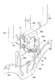
図2に示すように、シートクッションS1は、その骨格を構成するシートクッションフレームF1を内蔵し、シートバックS2は、その骨格を構成するシートバックフレームF2を内蔵している。なお、図示省略したが、ヘッドレストS3もその骨格を構成するヘッドレストフレームを内蔵している。 As shown in FIG. 2, the seat cushion S1 incorporates a seat cushion frame F1 constituting the skeleton, and the seat back S2 incorporates a seat back frame F2 constituting the skeleton. Although not shown, the headrest S3 also has a built-in headrest frame constituting its skeleton.
シートクッションフレームF1は、平面視において後部が開いた概略U字状にプレス成形されており、前部に板状のフロントフレーム11を有する。このフロントフレーム11の左右部分から後方に延出するクッションサイドフレーム12,12の後部間は、リヤ連結パイプ13を介して左右に連結されている。そして、このリヤ連結パイプ13とフロントフレーム11との間に、4本のシートクッションスプリング14が左右に並べて張設されている。このようなシートクッションフレームF1は、運転席のフロア上にスライドレールSLを介して前後方向に位置調節自在に設けられている。
The seat cushion frame F1 is press-molded into a substantially U shape with the rear portion open in a plan view, and has a plate-shaped
一方、シートバックフレームF2は、正面視において下部が開いた逆U字状にパイプ材を曲げ加工してなる上部パイプフレーム21と、この上部パイプフレーム21の左右の下部を包持した状態で溶接によりそれぞれ連結された左右のバックサイドフレーム22,22と、このバックサイドフレーム22,22の下端部間を連結する下部フレーム23とを有し、これらで縦長の長方形に枠組みされている。そして、このようなシートバックフレームF2の下部が、シートクッションフレームF1の左右のクッションサイドフレーム12,12の後端部に、リクライニングユニットRUを介して回動自在に連結されることで、シートバックフレームF2が前後に傾動可能となっている。
On the other hand, the seat back frame F2 is welded with the
シートバックフレームF2の上部パイプフレーム21の上部の水平部分には、図1に示したヘッドレストS3の下部から突出する左右一対のヘッドレストステー(符号省略)を装着するための左右一対のサポートブラケット24,24が溶接により固定されている。また、上部フレーム21の左右の縦部分の上部間には、受圧部材30の上部に補強部材25が架設されている。この補強部材25は、ロッドをシートバックフレームF2の平面にほぼ沿う左右対称の形状に曲げ加工したものである。
On the horizontal portion of the upper part of the
ここで、図2および図3に示すように、枠状のシートバックフレームF2の内側には、シートクッションS1に着座した乗員の上体を弾性的に後退移動可能に支持するための受圧部材30が配置されている。そして、この受圧部材30を前後方向に弾性的に支持するため、上部フレーム21の左右の縦部分の下部間には、上部支持ワイヤ26が張設され、左右のバックサイドフレーム22,22間には、下部支持ワイヤ27が張設されている。これらの上部支持ワイヤ26および下部支持ワイヤ27は、ばね弾性を有するピアノ線などのワイヤをシートバックフレームF2の平面にほぼ沿う左右対称の形状にそれぞれ曲げ加工した線状部材である。ここで、上部支持ワイヤ26または下部支持ワイヤ27を、振動ユニット50から離れるように湾曲させて設けると、上部支持ワイヤ26、下部支持ワイヤ27または振動ユニット50の取付作業性が向上するので望ましい。
Here, as shown in FIGS. 2 and 3, inside the frame-shaped seat back frame F2, a
上部支持ワイヤ26は、左右の両端部が上部フレーム21の左右の縦部分に沿うようにそれぞれ下方に屈曲している。そして、この上部支持ワイヤ26の左右の両端部は、上部フレーム21の左右の縦部分にそれぞれ溶接固定された支持舌片28,28に包持された状態で上部フレーム21の左右の縦部分に連結支持されている。この上部支持ワイヤ26は、左右の支持舌片28,28に連結支持された両端部よりも受圧部材30を支持する中間部分が低い位置となり、かつ、中間部分のうち、両側の支持部26A,26Aより中央の支持部26Bが高い位置となるように上下方向に山形に屈曲されている。
The left and right ends of the
下部支持ワイヤ27の左右の両端部は、左右のバックサイドフレーム22,22の内側面にそれぞれ設置されたトグル支持機構(右側のみ図2に表示)40に連結されている。この下部支持ワイヤ27は、トグル支持機構40に連結された両端部よりも受圧部材30を支持する中間部分が低い位置となり、かつ、中間部分のうち、両側の支持部27A,27Aより中央の支持部27Bが低い位置となるように上下方向に山形に屈曲されている。
The left and right ends of the
トグル支持機構40は、引張コイルばねの張力に抗しつつ思案点(機構上、いずれの方向に動くか決まらない点)を乗り越えて後方に揺動可能な揺動リンク部材を備えており、この揺動リンク部材に下部支持ワイヤ27の左右の両端部が連結されている。ここで、トグル支持機構40の引張コイルばねの張力は、下部支持ワイヤ27の両端部に所定値以上の後退移動荷重が作用した際に揺動リンク部材が思案点を乗り越えて後方に揺動できるような適宜の張力に設定されている。
The
ここで、受圧部材30は、シートクッションS1に着座した乗員の上体を弾性的に後退移動可能に支持するための樹脂製の板部材であり、例えば図4および図5に示すような形状、すなわち下方に頂点が向いた略五角形状に成形されている。この受圧部材30の後面(背面)には、図3に示した上部支持ワイヤ26の左右の支持部26A,26Aに上方から係合するフック状の保持部30A,30Aと、上部支持ワイヤ26の中央の支持部26Bに下方から係合するフック状の保持部30Bとが一体に成形されている。同様に、受圧部材30の後面(背面)には、図3に示した下部支持ワイヤ27の左右の支持部27A,27Aに上方から係合するフック状の保持部30C,30Cと、下部支持ワイヤ27の中央の支持部27Bに下方から係合するフック状の保持部30Dとが一体に成形されている。
Here, the
ここで、受圧部材30には、図6および図7に示すように、振動ユニット50を収容するための収容凹部30Eが一体に成形されている。この収容凹部30Eは、受圧部材30の前面(正面)に開口して後面(背面)に膨出しており、その正面視の形状は横長の長方形となっている。そして、受圧部材30の収容凹部30Eの長方形の開口の四隅の個所には、後述する取付けブラケット54を取り付けるための取付部材としてのナットNがインサート成形されて埋設されている。この収容凹部30Eの底部は、第1のカバー部材(干渉抑制部材)として機能し、振動ユニット50と、シートバックフレームF2の後側を覆うクッションパッドと振動ユニット50とが干渉することを抑制している。
Here, as shown in FIGS. 6 and 7, the
振動ユニット50は、駆動モータ(アクチュエータ)51と、駆動モータ51の回転軸52に取り付けられた振動錘53と、駆動モータ51に取り付けられた取付ブラケット54とで構成されている。振動錘53は、扇形の板が複数枚重ねられて正面視扇形のブロック状に一体化されたものであり、その重心から偏心した位置に回転軸52が取り付けられることで、回転軸52の回転に伴い所定周波数の振動を発生する。振動ユニット50が発生する振動は、駆動モータ51の回転数を変更することで、シートクッションS1に着座した乗員にマッサージ効果や覚醒効果などを与える適宜の周波数とすることができる。なお、振動ユニット50の作動を制御するコントローラは、例えば車両用シートSの前方の運転席に設置することができる。
The
取付ブラケット54は、図6に示した受圧部材30の4つのナットNのうち、少なくとも3つのナットNに合致するボルト挿通孔54Aを有する。ここで、本実施形態においては、取付ブラケット54と共に受圧部材30の前面(正面)に取り付けられるカバープレート55が第2のカバー部材(干渉抑制部材)として設けられている。このカバープレート55は、受圧部材30の収容凹部30Eを覆う大きさの長方形の板部材であり、その四隅には4つのナットNに合致するボルト挿通孔55Aがそれぞれ形成されている。このようなカバープレート55は、そのボルト挿通孔55Aおよび取付ブラケット54のボルト挿通孔54Aを通して受圧部材30の4つのナットNにねじ込まれる4本のボルトBにより、受圧部材30の前面(正面)に取り付けられて収容凹部30Eを覆っている。これによって、振動ユニット50は、受圧部材30に、バネ部材を介することなく取り付けられている。このため、部品点数を削減できる。
The mounting
続いて、本発明に係る乗物用シートの一実施形態として構成された車両用シートSにつき、その作用効果を説明する。図1に示した車両用シートSが運転席に配置された車両において、シートクッションS1に着座した乗員の上体からシートバックS2に作用する押圧力が所定範囲内にある通常運転時、あるいは停車時には、図2および図3に示した上部支持ワイヤ26および下部支持ワイヤ27が適度に後方に弾性変形することにより、乗員の上体が適度にシートバックS2に沈み込んで安定した運転姿勢に保持される。
Subsequently, the operation and effect of the vehicle seat S configured as one embodiment of the vehicle seat according to the present invention will be described. In a vehicle in which the vehicle seat S shown in FIG. 1 is arranged in the driver's seat, the pressing force acting on the seat back S2 from the upper body of the occupant seated on the seat cushion S1 is within a predetermined range during normal driving or when the vehicle is stopped. Occasionally, the
このように車両用シートSのシートクッションS1に着座した乗員の上体が適度にシートバックS2に沈み込んだ状態において、例えば車両用シートSの前方の運転席に設置された図示しないコントローラの操作により、振動ユニット50が作動すると、駆動モータ51の回転軸52と共に振動錘53が回転することで振動ユニット50が振動を発生する。そして、この振動ユニット50の振動が直接、バネ部材を介することなく、受圧部材30の全体に伝達され、受圧部材30からクッションパッドを介して乗員の上体および上体以外の部分に効率良く伝達される。
In the state where the upper body of the occupant seated on the seat cushion S1 of the vehicle seat S is appropriately submerged in the seat back S2, for example, the operation of a controller (not shown) installed in the driver's seat in front of the vehicle seat S. As a result, when the
すなわち、一実施形態の車両用シートSによれば、シートクッションS1に着座した乗員にマッサージ効果や覚醒効果などを与えるために振動ユニット50が発生する所望の振動をシートバックS2から乗員の上体に効率良く伝達することができる。この場合、受圧部材30の後面(背面)側に張り出す収容凹部30E内に振動ユニット50が収容されていて、受圧部材30の受圧面である前面より後方に振動ユニット50が配置されているため、シートバックS2に支持された乗員の上体に振動ユニット50が接触する違和感を解消することができる。
That is, according to the vehicle seat S of one embodiment, the desired vibration generated by the
また、一実施形態の車両用シートSによれば、振動ユニット50の取付ブラケット54と共にカバープレート55が受圧部材30の収容凹部30Eの周囲に取付(固定)されるため、振動ユニット50とクッションパッド(図示省略)との干渉を抑制して振動ユニット50を安定して作動させることができる。そして、振動ユニット50が収容された収容凹部30Eをカバープレート55が覆っているため、収容凹部30Eに埃が入るのを抑制することができる。また、収容凹部30Eの底部は、第1のカバー部材(干渉抑制部材)として機能し、振動ユニット50と、シートバックフレームF2の後側を覆うクッションパッドと振動ユニット50とが干渉することを抑制する。
Further, according to the vehicle seat S of one embodiment, the
さらに、振動ユニット50の取付ブラケット54を取り付けるための取付部材であるナットNが受圧部材30の収容凹部30Eの開口部の周囲にインサート成形されているため、取付ブラケット54の取り付け作業を容易に行うことができ、しかも、受圧部材30の剛性を高めて振動ユニット50の振動を受圧部材30の全体に効率良く伝達することができる。
Further, since the nut N, which is a mounting member for mounting the mounting
また、振動ユニット50が上部支持ワイヤ26および下部支持ワイヤ27と重ならない位置、すなわち、上部支持ワイヤ26と下部支持ワイヤ27との間の高さ位置に配置されているため、振動ユニット50の組み付け時に上部支持ワイヤ26および下部支持ワイヤ27が邪魔とならず、振動ユニット50の組付け作業性を向上させることができる。
Further, since the
さらに、上部支持ワイヤ26および下部支持ワイヤ27がシートバックフレームF2の左右部分を繋ぐように設けられており、上部支持ワイヤ26の中央の支持部26Bに下方から係合するフック状の保持部30Bと、下部支持ワイヤ27の中央の支持部27Bに下方から係合するフック状の保持部30Dとが振動ユニット50の上方および下方に並んで配置されており、受圧部材30の大きな振動が発生する部分において受圧部材30が上部支持ワイヤ26および下部支持ワイヤ27を保持するので、振動ユニット50が振動する際に、受圧部材30と線状部材である上部支持ワイヤ26および下部支持ワイヤ27との干渉による異音の発生を抑制することができる。
Further, the
以上、本発明に係る乗物用シートの一実施形態としての車両用シートSについて説明したが、本発明の乗物用シートは、一実施形態の車両用シートSに限定されるものではなく、その構造は適宜変更することができる。 Although the vehicle seat S as one embodiment of the vehicle seat according to the present invention has been described above, the vehicle seat S of the present invention is not limited to the vehicle seat S of one embodiment and has a structure thereof. Can be changed as appropriate.
例えば、図8〜図10に示すように、受圧部材30は、後面(背面)側に膨出する複数の縦ビード30Fや横ビード30Gを形成してもよい。この場合、複数の縦ビード30Fや横ビード30Gの存在により受圧部材30の剛性が高まるため、振動ユニット50が発生する振動を受圧部材30の全体に伝達することができる。
For example, as shown in FIGS. 8 to 10, the
また、図8および図9に示すように、振動ユニット50は、回転軸が上下方向に向く縦向きにして受圧部材30の後面(背面)側に設置することができる。この場合、振動ユニット50とクッションパッド(図示省略)との干渉を抑制して振動ユニット50を安定して作動させるため、駆動モータ51を覆うモータカバー部56Aと、モータカバー部56Aよりも外側に張り出して振動錘53の回転領域を覆う錘カバー部56Bとを有するカバー部材(第1のカバー部材、干渉抑制部材)56を設けるのが好ましい。このとき、モータカバー部56Aから錘カバー部56Bにかけて折れ曲がって段差状に外側に張り出す構成とすることができる。このカバー部材56は、振動ユニット50の取付ブラケット57と共締めにより受圧部材30に取り付けられる。
Further, as shown in FIGS. 8 and 9, the
さらに、図10に示すように、振動ユニット50は、回転軸が左右方向に向く横向きにして受圧部材30の後面(背面)側に設置することができる。この場合も、振動ユニット50とクッションパッド(図示省略)との干渉を抑制して振動ユニット50を安定して作動させるため、駆動モータ51を覆うモータカバー部58Aと、モータカバー部58Aよりも外側に張り出して振動錘53の回転領域を覆う錘カバー部58Bとを有するカバー部材(第1のカバー部材)58を設けるのが好ましい。このカバー部材58は、振動ユニット50の取付ブラケット59と共締めにより受圧部材30に取り付けられる。ここで振動ユニット50は、一部が、上下に並んだ2つの横ビード30Gの間に形成された凹部に入り込んでいることで、この凹部内の空間を有効に利用して、車両用シートSのコンパクト化を図ることができる。
Further, as shown in FIG. 10, the
これらの変形例のように、振動ユニット50の後側にカバー部材56,58を設けることで、シートバックフレームF2の後側を覆う背面カバー(被覆部材)と振動ユニット50とが干渉することが抑制される。また、カバー部材56,58は、モータカバー部56A,58Aと、錘カバー部56B,58Bとからなるため、コンパクト化を実現しつつ、偏心錘が振動したとしても背面カバーと干渉することを抑制することができる。また、モータカバー56A,58Aに対して錘カバー部56B,58Bが張り出した形状であるとカバー部材56,58の剛性を高くすることができる。
By providing the
前記実施形態においては、下部支持ワイヤ27は、両端部がトグル支持機構40に支持されていたが、一方の端部のみをトグル支持機構40に支持させてもよいし、トグル支持機構40を用いることなく、両端部を左右のサイドフレームに支持させてもよい。
In the above embodiment, both ends of the
前記実施形態においては、振動ユニット50は、受圧部材30の上下方向における中央付近に設けられていたが、中央よりも下に設けることもできる。受圧部材30がシートバックS2の下寄りに設けられている場合、通常、乗員の上体のうち下の方(腰部の周囲)はシートバックS2に接触しているので、振動ユニット50の振動を安定的に乗員に伝達することができる。
In the above-described embodiment, the
一実施形態の車両用シートSは、運転席が右側に配置された車両を対象として構成されているが、左右方向の構造を逆に構成することで、運転席が左側に配置された車両に適用できる。 The vehicle seat S of one embodiment is configured for a vehicle in which the driver's seat is arranged on the right side, but by reversing the structure in the left-right direction, the vehicle in which the driver's seat is arranged on the left side can be used. Applicable.
また、一実施形態の車両用シートSは、シートクッションS1とシートバックS2とヘッドレストS3とが一体に構成されたバケットタイプの車両用シートとして構成することもできる。 Further, the vehicle seat S of one embodiment can be configured as a bucket type vehicle seat in which the seat cushion S1, the seat back S2, and the headrest S3 are integrally formed.
さらに、本発明の乗物用シートは、船舶用や航空機用のシートとして構成することもできる。 Further, the vehicle seat of the present invention can also be configured as a seat for a ship or an aircraft.
F1 シートクッションフレーム
11 フロントフレーム
12 クッションサイドフレーム
13 リヤ連結パイプ
F2 シートバックフレーム
21 上部フレーム
22 バックサイドフレーム
23 下部フレーム
24 サポートブラケット
25 補強部材
26 上部支持ワイヤ
27 下部支持ワイヤ
28 支持舌片
30 受圧部材
30A 係合フック部
30B 係合フック部
30C 係合フック部
30D 係合フック部
30E 収容凹部
40 トグル支持機構
B ボルト
N ナット
RU リクライニングユニット
S 車両用シート
S1 シートクッション
S2 シートバック
S3 ヘッドレスト
SL スライドレール
F1
Claims (7)
前記乗物用シートは、骨格を構成するフレームと、当該フレームの内側に配置されて乗員を支持する受圧部材であって、左右方向に延びるとともに前記左右方向に直交する直交方向に延びる受圧部材と、前記フレームに前記受圧部材を弾性的に支持する支持ワイヤと、前記フレームおよび前記受圧部材を覆う被覆部材とを有し、
前記受圧部材は、前記支持ワイヤと係合する第1保持部を有し、
前記受圧部材には、前記第1保持部と前記直交方向で並ぶ振動ユニットが付設され、
前記振動ユニットは、駆動モータと、当該駆動モータの回転軸に取り付けられた振動錘とを有し、
前記乗物用シートは、前記受圧部材から前記左右方向および前記直交方向に直交する所定方向に張り出して前記駆動モータを覆うモータカバー部と、前記モータカバー部よりも前記所定方向において前記受圧部材から離れる方向に張り出して前記振動錘の回転領域を覆う錘カバー部とを有することを特徴とする乗物用シート。 A vehicle seat with at least a seat cushion and a seat back,
The vehicle seat includes a frame constituting a skeleton, a pressure receiving member arranged inside the frame to support an occupant, and a pressure receiving member extending in the left-right direction and extending in an orthogonal direction orthogonal to the left-right direction. The frame has a support wire that elastically supports the pressure receiving member, and a covering member that covers the frame and the pressure receiving member.
The pressure receiving member has a first holding portion that engages with the support wire.
A vibration unit arranged in the direction orthogonal to the first holding portion is attached to the pressure receiving member .
The vibrating unit has a drive motor and a vibrating weight attached to a rotating shaft of the drive motor.
The vehicle seat protrudes from the pressure receiving member in a predetermined direction orthogonal to the left-right direction and the orthogonal direction to cover the drive motor, and separates from the pressure receiving member in the predetermined direction from the motor cover portion. A vehicle seat characterized by having a weight cover portion that projects in a direction and covers a rotating region of the vibrating weight .
前記乗物用シートは、骨格を構成するフレームと、当該フレームの内側に配置されて乗員を支持する受圧部材であって、左右方向に延びるとともに前記左右方向に直交する直交方向に延びる受圧部材と、前記フレームに前記受圧部材を弾性的に支持する支持ワイヤと、前記フレームおよび前記受圧部材を覆う被覆部材とを有し、
前記受圧部材は、前記支持ワイヤと係合する第1保持部を有し、
前記受圧部材には、前記第1保持部と前記直交方向で並ぶ振動ユニットが付設され、
前記受圧部材は、前記振動ユニットを収容する収容凹部を有し、
前記乗物用シートは、前記振動ユニットを前記受圧部材に取り付けるための取付ブラケットと、前記収容凹部を覆うカバープレートとを備え、
前記取付ブラケットの一部は、前記収容凹部の開口の周囲に配置され、前記カバープレートとともに前記受圧部材に共締めされていることを特徴とする乗物用シート。 A vehicle seat with at least a seat cushion and a seat back,
The vehicle seat includes a frame constituting a skeleton, a pressure receiving member arranged inside the frame to support an occupant, and a pressure receiving member extending in the left-right direction and extending in an orthogonal direction orthogonal to the left-right direction. The frame has a support wire that elastically supports the pressure receiving member, and a covering member that covers the frame and the pressure receiving member.
The pressure receiving member has a first holding portion that engages with the support wire.
A vibration unit arranged in the direction orthogonal to the first holding portion is attached to the pressure receiving member .
The pressure receiving member has an accommodating recess for accommodating the vibration unit.
The vehicle seat includes a mounting bracket for mounting the vibration unit to the pressure receiving member, and a cover plate that covers the accommodating recess.
A vehicle seat characterized in that a part of the mounting bracket is arranged around the opening of the accommodating recess and is fastened together with the cover plate to the pressure receiving member .
前記錘カバー部は、前記所定方向において前記振動錘と対向する第2壁と、前記第2壁と前記第1壁とに連結される第3壁とを有し、 The weight cover portion has a second wall facing the vibrating weight in the predetermined direction, and a third wall connected to the second wall and the first wall.
前記第3壁は、前記所定方向に対して傾斜していることを特徴とする請求項1に記載の乗物用シート。 The vehicle seat according to claim 1, wherein the third wall is inclined with respect to the predetermined direction.
前記直交方向において、前記第1保持部は、前記第2保持部よりも前記振動ユニットから離れていることを特徴とする請求項1から請求項4のいずれか1項に記載の乗物用シート。 The pressure receiving member is a second holding portion that engages with the support wire, and has two second holding portions arranged on both left and right sides of the first holding portion.
The vehicle seat according to any one of claims 1 to 4 , wherein the first holding portion is separated from the vibration unit by the second holding portion in the orthogonal direction.
前記ビードは、前記直交方向において、前記第1保持部に対して前記振動ユニットと同じ側に配置されることを特徴とする請求項1から請求項5のいずれか1項に記載の乗物用シート。 The pressure receiving member has a bead and has a bead.
The vehicle seat according to any one of claims 1 to 5 , wherein the bead is arranged on the same side as the vibration unit with respect to the first holding portion in the orthogonal direction. ..
Priority Applications (1)
| Application Number | Priority Date | Filing Date | Title |
|---|---|---|---|
| JP2019186542A JP6777876B2 (en) | 2019-10-10 | 2019-10-10 | Vehicle seat |
Applications Claiming Priority (1)
| Application Number | Priority Date | Filing Date | Title |
|---|---|---|---|
| JP2019186542A JP6777876B2 (en) | 2019-10-10 | 2019-10-10 | Vehicle seat |
Related Parent Applications (1)
| Application Number | Title | Priority Date | Filing Date |
|---|---|---|---|
| JP2018116853A Division JP6601535B2 (en) | 2018-06-20 | 2018-06-20 | Vehicle seat |
Related Child Applications (1)
| Application Number | Title | Priority Date | Filing Date |
|---|---|---|---|
| JP2020170727A Division JP7132528B2 (en) | 2020-10-08 | 2020-10-08 | vehicle seat |
Publications (3)
| Publication Number | Publication Date |
|---|---|
| JP2020001700A JP2020001700A (en) | 2020-01-09 |
| JP2020001700A5 JP2020001700A5 (en) | 2020-02-20 |
| JP6777876B2 true JP6777876B2 (en) | 2020-10-28 |
Family
ID=69098525
Family Applications (1)
| Application Number | Title | Priority Date | Filing Date |
|---|---|---|---|
| JP2019186542A Active JP6777876B2 (en) | 2019-10-10 | 2019-10-10 | Vehicle seat |
Country Status (1)
| Country | Link |
|---|---|
| JP (1) | JP6777876B2 (en) |
Family Cites Families (3)
| Publication number | Priority date | Publication date | Assignee | Title |
|---|---|---|---|---|
| JPS6054453U (en) * | 1983-09-22 | 1985-04-17 | 株式会社タチエス | Seat with vibrating body |
| JP3492733B2 (en) * | 1993-11-02 | 2004-02-03 | デルタ工業株式会社 | Car seat |
| JP5503153B2 (en) * | 2009-01-26 | 2014-05-28 | テイ・エス テック株式会社 | Vehicle seat |
-
2019
- 2019-10-10 JP JP2019186542A patent/JP6777876B2/en active Active
Also Published As
| Publication number | Publication date |
|---|---|
| JP2020001700A (en) | 2020-01-09 |
Similar Documents
| Publication | Publication Date | Title |
|---|---|---|
| JP5903301B2 (en) | Vehicle seat | |
| JP2016105868A (en) | Vehicle seat | |
| JP2019048626A (en) | Seat device for vehicle | |
| JP6627607B2 (en) | Vehicle seat | |
| JP5361321B2 (en) | Vehicle seat | |
| JP5696706B2 (en) | Headrest and vehicle seat provided with the same | |
| JP5988578B2 (en) | Sheet | |
| JP5863521B2 (en) | Vehicle seat | |
| JP6777876B2 (en) | Vehicle seat | |
| JP6601535B2 (en) | Vehicle seat | |
| JP5827155B2 (en) | Vehicle seat | |
| JP2021004037A (en) | Vehicle seat | |
| JP2020001700A5 (en) | ||
| JP2021183493A (en) | Vehicle seat | |
| JP6849930B2 (en) | Vehicle seat | |
| JP6495418B2 (en) | Vehicle seat | |
| JP2018197035A (en) | Vehicular seat | |
| JP6649934B2 (en) | Seats and vehicles | |
| JP5696649B2 (en) | Headrest and vehicle seat | |
| JP6239850B2 (en) | Vehicle seat | |
| JP6721847B2 (en) | Seat frame and vehicle seat | |
| JP6766695B2 (en) | Vehicle seat | |
| JP4141939B2 (en) | Car seat | |
| JP2013199159A (en) | Vehicle seat | |
| JP7100240B2 (en) | Vehicle seat |
Legal Events
| Date | Code | Title | Description |
|---|---|---|---|
| A621 | Written request for application examination |
Free format text: JAPANESE INTERMEDIATE CODE: A621 Effective date: 20191108 |
|
| A521 | Request for written amendment filed |
Free format text: JAPANESE INTERMEDIATE CODE: A523 Effective date: 20191204 |
|
| A131 | Notification of reasons for refusal |
Free format text: JAPANESE INTERMEDIATE CODE: A131 Effective date: 20200623 |
|
| A521 | Request for written amendment filed |
Free format text: JAPANESE INTERMEDIATE CODE: A523 Effective date: 20200820 |
|
| TRDD | Decision of grant or rejection written | ||
| A01 | Written decision to grant a patent or to grant a registration (utility model) |
Free format text: JAPANESE INTERMEDIATE CODE: A01 Effective date: 20200908 |
|
| A61 | First payment of annual fees (during grant procedure) |
Free format text: JAPANESE INTERMEDIATE CODE: A61 Effective date: 20200921 |
|
| R150 | Certificate of patent or registration of utility model |
Ref document number: 6777876 Country of ref document: JP Free format text: JAPANESE INTERMEDIATE CODE: R150 |
|
| R250 | Receipt of annual fees |
Free format text: JAPANESE INTERMEDIATE CODE: R250 |