JP6776370B2 - Gas storage and processing equipment - Google Patents
Gas storage and processing equipment Download PDFInfo
- Publication number
- JP6776370B2 JP6776370B2 JP2018557373A JP2018557373A JP6776370B2 JP 6776370 B2 JP6776370 B2 JP 6776370B2 JP 2018557373 A JP2018557373 A JP 2018557373A JP 2018557373 A JP2018557373 A JP 2018557373A JP 6776370 B2 JP6776370 B2 JP 6776370B2
- Authority
- JP
- Japan
- Prior art keywords
- gas
- pipe
- tank
- heat exchanger
- channel
- Prior art date
- Legal status (The legal status is an assumption and is not a legal conclusion. Google has not performed a legal analysis and makes no representation as to the accuracy of the status listed.)
- Active
Links
Images


Classifications
-
- F—MECHANICAL ENGINEERING; LIGHTING; HEATING; WEAPONS; BLASTING
- F17—STORING OR DISTRIBUTING GASES OR LIQUIDS
- F17C—VESSELS FOR CONTAINING OR STORING COMPRESSED, LIQUEFIED OR SOLIDIFIED GASES; FIXED-CAPACITY GAS-HOLDERS; FILLING VESSELS WITH, OR DISCHARGING FROM VESSELS, COMPRESSED, LIQUEFIED, OR SOLIDIFIED GASES
- F17C9/00—Methods or apparatus for discharging liquefied or solidified gases from vessels not under pressure
- F17C9/02—Methods or apparatus for discharging liquefied or solidified gases from vessels not under pressure with change of state, e.g. vaporisation
- F17C9/04—Recovery of thermal energy
-
- F—MECHANICAL ENGINEERING; LIGHTING; HEATING; WEAPONS; BLASTING
- F17—STORING OR DISTRIBUTING GASES OR LIQUIDS
- F17C—VESSELS FOR CONTAINING OR STORING COMPRESSED, LIQUEFIED OR SOLIDIFIED GASES; FIXED-CAPACITY GAS-HOLDERS; FILLING VESSELS WITH, OR DISCHARGING FROM VESSELS, COMPRESSED, LIQUEFIED, OR SOLIDIFIED GASES
- F17C13/00—Details of vessels or of the filling or discharging of vessels
- F17C13/004—Details of vessels or of the filling or discharging of vessels for large storage vessels not under pressure
-
- F—MECHANICAL ENGINEERING; LIGHTING; HEATING; WEAPONS; BLASTING
- F25—REFRIGERATION OR COOLING; COMBINED HEATING AND REFRIGERATION SYSTEMS; HEAT PUMP SYSTEMS; MANUFACTURE OR STORAGE OF ICE; LIQUEFACTION SOLIDIFICATION OF GASES
- F25J—LIQUEFACTION, SOLIDIFICATION OR SEPARATION OF GASES OR GASEOUS OR LIQUEFIED GASEOUS MIXTURES BY PRESSURE AND COLD TREATMENT OR BY BRINGING THEM INTO THE SUPERCRITICAL STATE
- F25J1/00—Processes or apparatus for liquefying or solidifying gases or gaseous mixtures
- F25J1/0002—Processes or apparatus for liquefying or solidifying gases or gaseous mixtures characterised by the fluid to be liquefied
- F25J1/0022—Hydrocarbons, e.g. natural gas
-
- F—MECHANICAL ENGINEERING; LIGHTING; HEATING; WEAPONS; BLASTING
- F17—STORING OR DISTRIBUTING GASES OR LIQUIDS
- F17C—VESSELS FOR CONTAINING OR STORING COMPRESSED, LIQUEFIED OR SOLIDIFIED GASES; FIXED-CAPACITY GAS-HOLDERS; FILLING VESSELS WITH, OR DISCHARGING FROM VESSELS, COMPRESSED, LIQUEFIED, OR SOLIDIFIED GASES
- F17C13/00—Details of vessels or of the filling or discharging of vessels
-
- F—MECHANICAL ENGINEERING; LIGHTING; HEATING; WEAPONS; BLASTING
- F17—STORING OR DISTRIBUTING GASES OR LIQUIDS
- F17C—VESSELS FOR CONTAINING OR STORING COMPRESSED, LIQUEFIED OR SOLIDIFIED GASES; FIXED-CAPACITY GAS-HOLDERS; FILLING VESSELS WITH, OR DISCHARGING FROM VESSELS, COMPRESSED, LIQUEFIED, OR SOLIDIFIED GASES
- F17C2201/00—Vessel construction, in particular geometry, arrangement or size
- F17C2201/05—Size
- F17C2201/052—Size large (>1000 m3)
-
- F—MECHANICAL ENGINEERING; LIGHTING; HEATING; WEAPONS; BLASTING
- F17—STORING OR DISTRIBUTING GASES OR LIQUIDS
- F17C—VESSELS FOR CONTAINING OR STORING COMPRESSED, LIQUEFIED OR SOLIDIFIED GASES; FIXED-CAPACITY GAS-HOLDERS; FILLING VESSELS WITH, OR DISCHARGING FROM VESSELS, COMPRESSED, LIQUEFIED, OR SOLIDIFIED GASES
- F17C2205/00—Vessel construction, in particular mounting arrangements, attachments or identifications means
- F17C2205/03—Fluid connections, filters, valves, closure means or other attachments
- F17C2205/0302—Fittings, valves, filters, or components in connection with the gas storage device
- F17C2205/0352—Pipes
- F17C2205/0355—Insulation thereof
-
- F—MECHANICAL ENGINEERING; LIGHTING; HEATING; WEAPONS; BLASTING
- F17—STORING OR DISTRIBUTING GASES OR LIQUIDS
- F17C—VESSELS FOR CONTAINING OR STORING COMPRESSED, LIQUEFIED OR SOLIDIFIED GASES; FIXED-CAPACITY GAS-HOLDERS; FILLING VESSELS WITH, OR DISCHARGING FROM VESSELS, COMPRESSED, LIQUEFIED, OR SOLIDIFIED GASES
- F17C2205/00—Vessel construction, in particular mounting arrangements, attachments or identifications means
- F17C2205/03—Fluid connections, filters, valves, closure means or other attachments
- F17C2205/0302—Fittings, valves, filters, or components in connection with the gas storage device
- F17C2205/0352—Pipes
- F17C2205/0358—Pipes coaxial
-
- F—MECHANICAL ENGINEERING; LIGHTING; HEATING; WEAPONS; BLASTING
- F17—STORING OR DISTRIBUTING GASES OR LIQUIDS
- F17C—VESSELS FOR CONTAINING OR STORING COMPRESSED, LIQUEFIED OR SOLIDIFIED GASES; FIXED-CAPACITY GAS-HOLDERS; FILLING VESSELS WITH, OR DISCHARGING FROM VESSELS, COMPRESSED, LIQUEFIED, OR SOLIDIFIED GASES
- F17C2205/00—Vessel construction, in particular mounting arrangements, attachments or identifications means
- F17C2205/03—Fluid connections, filters, valves, closure means or other attachments
- F17C2205/0302—Fittings, valves, filters, or components in connection with the gas storage device
- F17C2205/0352—Pipes
- F17C2205/0367—Arrangements in parallel
-
- F—MECHANICAL ENGINEERING; LIGHTING; HEATING; WEAPONS; BLASTING
- F17—STORING OR DISTRIBUTING GASES OR LIQUIDS
- F17C—VESSELS FOR CONTAINING OR STORING COMPRESSED, LIQUEFIED OR SOLIDIFIED GASES; FIXED-CAPACITY GAS-HOLDERS; FILLING VESSELS WITH, OR DISCHARGING FROM VESSELS, COMPRESSED, LIQUEFIED, OR SOLIDIFIED GASES
- F17C2221/00—Handled fluid, in particular type of fluid
- F17C2221/03—Mixtures
- F17C2221/032—Hydrocarbons
- F17C2221/033—Methane, e.g. natural gas, CNG, LNG, GNL, GNC, PLNG
-
- F—MECHANICAL ENGINEERING; LIGHTING; HEATING; WEAPONS; BLASTING
- F17—STORING OR DISTRIBUTING GASES OR LIQUIDS
- F17C—VESSELS FOR CONTAINING OR STORING COMPRESSED, LIQUEFIED OR SOLIDIFIED GASES; FIXED-CAPACITY GAS-HOLDERS; FILLING VESSELS WITH, OR DISCHARGING FROM VESSELS, COMPRESSED, LIQUEFIED, OR SOLIDIFIED GASES
- F17C2221/00—Handled fluid, in particular type of fluid
- F17C2221/03—Mixtures
- F17C2221/032—Hydrocarbons
- F17C2221/035—Propane butane, e.g. LPG, GPL
-
- F—MECHANICAL ENGINEERING; LIGHTING; HEATING; WEAPONS; BLASTING
- F17—STORING OR DISTRIBUTING GASES OR LIQUIDS
- F17C—VESSELS FOR CONTAINING OR STORING COMPRESSED, LIQUEFIED OR SOLIDIFIED GASES; FIXED-CAPACITY GAS-HOLDERS; FILLING VESSELS WITH, OR DISCHARGING FROM VESSELS, COMPRESSED, LIQUEFIED, OR SOLIDIFIED GASES
- F17C2223/00—Handled fluid before transfer, i.e. state of fluid when stored in the vessel or before transfer from the vessel
- F17C2223/01—Handled fluid before transfer, i.e. state of fluid when stored in the vessel or before transfer from the vessel characterised by the phase
- F17C2223/0146—Two-phase
- F17C2223/0153—Liquefied gas, e.g. LPG, GPL
- F17C2223/0161—Liquefied gas, e.g. LPG, GPL cryogenic, e.g. LNG, GNL, PLNG
-
- F—MECHANICAL ENGINEERING; LIGHTING; HEATING; WEAPONS; BLASTING
- F17—STORING OR DISTRIBUTING GASES OR LIQUIDS
- F17C—VESSELS FOR CONTAINING OR STORING COMPRESSED, LIQUEFIED OR SOLIDIFIED GASES; FIXED-CAPACITY GAS-HOLDERS; FILLING VESSELS WITH, OR DISCHARGING FROM VESSELS, COMPRESSED, LIQUEFIED, OR SOLIDIFIED GASES
- F17C2223/00—Handled fluid before transfer, i.e. state of fluid when stored in the vessel or before transfer from the vessel
- F17C2223/03—Handled fluid before transfer, i.e. state of fluid when stored in the vessel or before transfer from the vessel characterised by the pressure level
- F17C2223/033—Small pressure, e.g. for liquefied gas
-
- F—MECHANICAL ENGINEERING; LIGHTING; HEATING; WEAPONS; BLASTING
- F17—STORING OR DISTRIBUTING GASES OR LIQUIDS
- F17C—VESSELS FOR CONTAINING OR STORING COMPRESSED, LIQUEFIED OR SOLIDIFIED GASES; FIXED-CAPACITY GAS-HOLDERS; FILLING VESSELS WITH, OR DISCHARGING FROM VESSELS, COMPRESSED, LIQUEFIED, OR SOLIDIFIED GASES
- F17C2223/00—Handled fluid before transfer, i.e. state of fluid when stored in the vessel or before transfer from the vessel
- F17C2223/04—Handled fluid before transfer, i.e. state of fluid when stored in the vessel or before transfer from the vessel characterised by other properties of handled fluid before transfer
- F17C2223/042—Localisation of the removal point
- F17C2223/043—Localisation of the removal point in the gas
-
- F—MECHANICAL ENGINEERING; LIGHTING; HEATING; WEAPONS; BLASTING
- F17—STORING OR DISTRIBUTING GASES OR LIQUIDS
- F17C—VESSELS FOR CONTAINING OR STORING COMPRESSED, LIQUEFIED OR SOLIDIFIED GASES; FIXED-CAPACITY GAS-HOLDERS; FILLING VESSELS WITH, OR DISCHARGING FROM VESSELS, COMPRESSED, LIQUEFIED, OR SOLIDIFIED GASES
- F17C2225/00—Handled fluid after transfer, i.e. state of fluid after transfer from the vessel
- F17C2225/01—Handled fluid after transfer, i.e. state of fluid after transfer from the vessel characterised by the phase
- F17C2225/0107—Single phase
- F17C2225/0123—Single phase gaseous, e.g. CNG, GNC
-
- F—MECHANICAL ENGINEERING; LIGHTING; HEATING; WEAPONS; BLASTING
- F17—STORING OR DISTRIBUTING GASES OR LIQUIDS
- F17C—VESSELS FOR CONTAINING OR STORING COMPRESSED, LIQUEFIED OR SOLIDIFIED GASES; FIXED-CAPACITY GAS-HOLDERS; FILLING VESSELS WITH, OR DISCHARGING FROM VESSELS, COMPRESSED, LIQUEFIED, OR SOLIDIFIED GASES
- F17C2225/00—Handled fluid after transfer, i.e. state of fluid after transfer from the vessel
- F17C2225/01—Handled fluid after transfer, i.e. state of fluid after transfer from the vessel characterised by the phase
- F17C2225/0146—Two-phase
- F17C2225/0153—Liquefied gas, e.g. LPG, GPL
- F17C2225/0161—Liquefied gas, e.g. LPG, GPL cryogenic, e.g. LNG, GNL, PLNG
-
- F—MECHANICAL ENGINEERING; LIGHTING; HEATING; WEAPONS; BLASTING
- F17—STORING OR DISTRIBUTING GASES OR LIQUIDS
- F17C—VESSELS FOR CONTAINING OR STORING COMPRESSED, LIQUEFIED OR SOLIDIFIED GASES; FIXED-CAPACITY GAS-HOLDERS; FILLING VESSELS WITH, OR DISCHARGING FROM VESSELS, COMPRESSED, LIQUEFIED, OR SOLIDIFIED GASES
- F17C2225/00—Handled fluid after transfer, i.e. state of fluid after transfer from the vessel
- F17C2225/03—Handled fluid after transfer, i.e. state of fluid after transfer from the vessel characterised by the pressure level
- F17C2225/033—Small pressure, e.g. for liquefied gas
-
- F—MECHANICAL ENGINEERING; LIGHTING; HEATING; WEAPONS; BLASTING
- F17—STORING OR DISTRIBUTING GASES OR LIQUIDS
- F17C—VESSELS FOR CONTAINING OR STORING COMPRESSED, LIQUEFIED OR SOLIDIFIED GASES; FIXED-CAPACITY GAS-HOLDERS; FILLING VESSELS WITH, OR DISCHARGING FROM VESSELS, COMPRESSED, LIQUEFIED, OR SOLIDIFIED GASES
- F17C2225/00—Handled fluid after transfer, i.e. state of fluid after transfer from the vessel
- F17C2225/03—Handled fluid after transfer, i.e. state of fluid after transfer from the vessel characterised by the pressure level
- F17C2225/036—Very high pressure, i.e. above 80 bars
-
- F—MECHANICAL ENGINEERING; LIGHTING; HEATING; WEAPONS; BLASTING
- F17—STORING OR DISTRIBUTING GASES OR LIQUIDS
- F17C—VESSELS FOR CONTAINING OR STORING COMPRESSED, LIQUEFIED OR SOLIDIFIED GASES; FIXED-CAPACITY GAS-HOLDERS; FILLING VESSELS WITH, OR DISCHARGING FROM VESSELS, COMPRESSED, LIQUEFIED, OR SOLIDIFIED GASES
- F17C2227/00—Transfer of fluids, i.e. method or means for transferring the fluid; Heat exchange with the fluid
- F17C2227/01—Propulsion of the fluid
- F17C2227/0128—Propulsion of the fluid with pumps or compressors
- F17C2227/0157—Compressors
- F17C2227/0164—Compressors with specified compressor type, e.g. piston or impulsive type
-
- F—MECHANICAL ENGINEERING; LIGHTING; HEATING; WEAPONS; BLASTING
- F17—STORING OR DISTRIBUTING GASES OR LIQUIDS
- F17C—VESSELS FOR CONTAINING OR STORING COMPRESSED, LIQUEFIED OR SOLIDIFIED GASES; FIXED-CAPACITY GAS-HOLDERS; FILLING VESSELS WITH, OR DISCHARGING FROM VESSELS, COMPRESSED, LIQUEFIED, OR SOLIDIFIED GASES
- F17C2227/00—Transfer of fluids, i.e. method or means for transferring the fluid; Heat exchange with the fluid
- F17C2227/03—Heat exchange with the fluid
- F17C2227/0302—Heat exchange with the fluid by heating
- F17C2227/0306—Heat exchange with the fluid by heating using the same fluid
-
- F—MECHANICAL ENGINEERING; LIGHTING; HEATING; WEAPONS; BLASTING
- F17—STORING OR DISTRIBUTING GASES OR LIQUIDS
- F17C—VESSELS FOR CONTAINING OR STORING COMPRESSED, LIQUEFIED OR SOLIDIFIED GASES; FIXED-CAPACITY GAS-HOLDERS; FILLING VESSELS WITH, OR DISCHARGING FROM VESSELS, COMPRESSED, LIQUEFIED, OR SOLIDIFIED GASES
- F17C2227/00—Transfer of fluids, i.e. method or means for transferring the fluid; Heat exchange with the fluid
- F17C2227/03—Heat exchange with the fluid
- F17C2227/0302—Heat exchange with the fluid by heating
- F17C2227/0309—Heat exchange with the fluid by heating using another fluid
-
- F—MECHANICAL ENGINEERING; LIGHTING; HEATING; WEAPONS; BLASTING
- F17—STORING OR DISTRIBUTING GASES OR LIQUIDS
- F17C—VESSELS FOR CONTAINING OR STORING COMPRESSED, LIQUEFIED OR SOLIDIFIED GASES; FIXED-CAPACITY GAS-HOLDERS; FILLING VESSELS WITH, OR DISCHARGING FROM VESSELS, COMPRESSED, LIQUEFIED, OR SOLIDIFIED GASES
- F17C2227/00—Transfer of fluids, i.e. method or means for transferring the fluid; Heat exchange with the fluid
- F17C2227/03—Heat exchange with the fluid
- F17C2227/0302—Heat exchange with the fluid by heating
- F17C2227/0327—Heat exchange with the fluid by heating with recovery of heat
-
- F—MECHANICAL ENGINEERING; LIGHTING; HEATING; WEAPONS; BLASTING
- F17—STORING OR DISTRIBUTING GASES OR LIQUIDS
- F17C—VESSELS FOR CONTAINING OR STORING COMPRESSED, LIQUEFIED OR SOLIDIFIED GASES; FIXED-CAPACITY GAS-HOLDERS; FILLING VESSELS WITH, OR DISCHARGING FROM VESSELS, COMPRESSED, LIQUEFIED, OR SOLIDIFIED GASES
- F17C2227/00—Transfer of fluids, i.e. method or means for transferring the fluid; Heat exchange with the fluid
- F17C2227/03—Heat exchange with the fluid
- F17C2227/0337—Heat exchange with the fluid by cooling
- F17C2227/0339—Heat exchange with the fluid by cooling using the same fluid
-
- F—MECHANICAL ENGINEERING; LIGHTING; HEATING; WEAPONS; BLASTING
- F17—STORING OR DISTRIBUTING GASES OR LIQUIDS
- F17C—VESSELS FOR CONTAINING OR STORING COMPRESSED, LIQUEFIED OR SOLIDIFIED GASES; FIXED-CAPACITY GAS-HOLDERS; FILLING VESSELS WITH, OR DISCHARGING FROM VESSELS, COMPRESSED, LIQUEFIED, OR SOLIDIFIED GASES
- F17C2227/00—Transfer of fluids, i.e. method or means for transferring the fluid; Heat exchange with the fluid
- F17C2227/03—Heat exchange with the fluid
- F17C2227/0337—Heat exchange with the fluid by cooling
- F17C2227/0341—Heat exchange with the fluid by cooling using another fluid
- F17C2227/0348—Water cooling
- F17C2227/0351—Water cooling using seawater
-
- F—MECHANICAL ENGINEERING; LIGHTING; HEATING; WEAPONS; BLASTING
- F17—STORING OR DISTRIBUTING GASES OR LIQUIDS
- F17C—VESSELS FOR CONTAINING OR STORING COMPRESSED, LIQUEFIED OR SOLIDIFIED GASES; FIXED-CAPACITY GAS-HOLDERS; FILLING VESSELS WITH, OR DISCHARGING FROM VESSELS, COMPRESSED, LIQUEFIED, OR SOLIDIFIED GASES
- F17C2227/00—Transfer of fluids, i.e. method or means for transferring the fluid; Heat exchange with the fluid
- F17C2227/03—Heat exchange with the fluid
- F17C2227/0337—Heat exchange with the fluid by cooling
- F17C2227/0358—Heat exchange with the fluid by cooling by expansion
- F17C2227/036—"Joule-Thompson" effect
-
- F—MECHANICAL ENGINEERING; LIGHTING; HEATING; WEAPONS; BLASTING
- F17—STORING OR DISTRIBUTING GASES OR LIQUIDS
- F17C—VESSELS FOR CONTAINING OR STORING COMPRESSED, LIQUEFIED OR SOLIDIFIED GASES; FIXED-CAPACITY GAS-HOLDERS; FILLING VESSELS WITH, OR DISCHARGING FROM VESSELS, COMPRESSED, LIQUEFIED, OR SOLIDIFIED GASES
- F17C2250/00—Accessories; Control means; Indicating, measuring or monitoring of parameters
- F17C2250/04—Indicating or measuring of parameters as input values
- F17C2250/0404—Parameters indicated or measured
- F17C2250/0443—Flow or movement of content
-
- F—MECHANICAL ENGINEERING; LIGHTING; HEATING; WEAPONS; BLASTING
- F17—STORING OR DISTRIBUTING GASES OR LIQUIDS
- F17C—VESSELS FOR CONTAINING OR STORING COMPRESSED, LIQUEFIED OR SOLIDIFIED GASES; FIXED-CAPACITY GAS-HOLDERS; FILLING VESSELS WITH, OR DISCHARGING FROM VESSELS, COMPRESSED, LIQUEFIED, OR SOLIDIFIED GASES
- F17C2250/00—Accessories; Control means; Indicating, measuring or monitoring of parameters
- F17C2250/06—Controlling or regulating of parameters as output values
- F17C2250/0605—Parameters
- F17C2250/0636—Flow or movement of content
-
- F—MECHANICAL ENGINEERING; LIGHTING; HEATING; WEAPONS; BLASTING
- F17—STORING OR DISTRIBUTING GASES OR LIQUIDS
- F17C—VESSELS FOR CONTAINING OR STORING COMPRESSED, LIQUEFIED OR SOLIDIFIED GASES; FIXED-CAPACITY GAS-HOLDERS; FILLING VESSELS WITH, OR DISCHARGING FROM VESSELS, COMPRESSED, LIQUEFIED, OR SOLIDIFIED GASES
- F17C2260/00—Purposes of gas storage and gas handling
- F17C2260/03—Dealing with losses
- F17C2260/031—Dealing with losses due to heat transfer
-
- F—MECHANICAL ENGINEERING; LIGHTING; HEATING; WEAPONS; BLASTING
- F17—STORING OR DISTRIBUTING GASES OR LIQUIDS
- F17C—VESSELS FOR CONTAINING OR STORING COMPRESSED, LIQUEFIED OR SOLIDIFIED GASES; FIXED-CAPACITY GAS-HOLDERS; FILLING VESSELS WITH, OR DISCHARGING FROM VESSELS, COMPRESSED, LIQUEFIED, OR SOLIDIFIED GASES
- F17C2265/00—Effects achieved by gas storage or gas handling
- F17C2265/03—Treating the boil-off
- F17C2265/032—Treating the boil-off by recovery
- F17C2265/033—Treating the boil-off by recovery with cooling
- F17C2265/034—Treating the boil-off by recovery with cooling with condensing the gas phase
-
- F—MECHANICAL ENGINEERING; LIGHTING; HEATING; WEAPONS; BLASTING
- F17—STORING OR DISTRIBUTING GASES OR LIQUIDS
- F17C—VESSELS FOR CONTAINING OR STORING COMPRESSED, LIQUEFIED OR SOLIDIFIED GASES; FIXED-CAPACITY GAS-HOLDERS; FILLING VESSELS WITH, OR DISCHARGING FROM VESSELS, COMPRESSED, LIQUEFIED, OR SOLIDIFIED GASES
- F17C2265/00—Effects achieved by gas storage or gas handling
- F17C2265/03—Treating the boil-off
- F17C2265/032—Treating the boil-off by recovery
- F17C2265/036—Treating the boil-off by recovery with heating
-
- F—MECHANICAL ENGINEERING; LIGHTING; HEATING; WEAPONS; BLASTING
- F17—STORING OR DISTRIBUTING GASES OR LIQUIDS
- F17C—VESSELS FOR CONTAINING OR STORING COMPRESSED, LIQUEFIED OR SOLIDIFIED GASES; FIXED-CAPACITY GAS-HOLDERS; FILLING VESSELS WITH, OR DISCHARGING FROM VESSELS, COMPRESSED, LIQUEFIED, OR SOLIDIFIED GASES
- F17C2265/00—Effects achieved by gas storage or gas handling
- F17C2265/03—Treating the boil-off
- F17C2265/032—Treating the boil-off by recovery
- F17C2265/037—Treating the boil-off by recovery with pressurising
-
- F—MECHANICAL ENGINEERING; LIGHTING; HEATING; WEAPONS; BLASTING
- F17—STORING OR DISTRIBUTING GASES OR LIQUIDS
- F17C—VESSELS FOR CONTAINING OR STORING COMPRESSED, LIQUEFIED OR SOLIDIFIED GASES; FIXED-CAPACITY GAS-HOLDERS; FILLING VESSELS WITH, OR DISCHARGING FROM VESSELS, COMPRESSED, LIQUEFIED, OR SOLIDIFIED GASES
- F17C2265/00—Effects achieved by gas storage or gas handling
- F17C2265/03—Treating the boil-off
- F17C2265/032—Treating the boil-off by recovery
- F17C2265/038—Treating the boil-off by recovery with expanding
-
- F—MECHANICAL ENGINEERING; LIGHTING; HEATING; WEAPONS; BLASTING
- F17—STORING OR DISTRIBUTING GASES OR LIQUIDS
- F17C—VESSELS FOR CONTAINING OR STORING COMPRESSED, LIQUEFIED OR SOLIDIFIED GASES; FIXED-CAPACITY GAS-HOLDERS; FILLING VESSELS WITH, OR DISCHARGING FROM VESSELS, COMPRESSED, LIQUEFIED, OR SOLIDIFIED GASES
- F17C2265/00—Effects achieved by gas storage or gas handling
- F17C2265/05—Regasification
-
- F—MECHANICAL ENGINEERING; LIGHTING; HEATING; WEAPONS; BLASTING
- F17—STORING OR DISTRIBUTING GASES OR LIQUIDS
- F17C—VESSELS FOR CONTAINING OR STORING COMPRESSED, LIQUEFIED OR SOLIDIFIED GASES; FIXED-CAPACITY GAS-HOLDERS; FILLING VESSELS WITH, OR DISCHARGING FROM VESSELS, COMPRESSED, LIQUEFIED, OR SOLIDIFIED GASES
- F17C2265/00—Effects achieved by gas storage or gas handling
- F17C2265/06—Fluid distribution
- F17C2265/066—Fluid distribution for feeding engines for propulsion
-
- F—MECHANICAL ENGINEERING; LIGHTING; HEATING; WEAPONS; BLASTING
- F17—STORING OR DISTRIBUTING GASES OR LIQUIDS
- F17C—VESSELS FOR CONTAINING OR STORING COMPRESSED, LIQUEFIED OR SOLIDIFIED GASES; FIXED-CAPACITY GAS-HOLDERS; FILLING VESSELS WITH, OR DISCHARGING FROM VESSELS, COMPRESSED, LIQUEFIED, OR SOLIDIFIED GASES
- F17C2265/00—Effects achieved by gas storage or gas handling
- F17C2265/07—Generating electrical power as side effect
-
- F—MECHANICAL ENGINEERING; LIGHTING; HEATING; WEAPONS; BLASTING
- F17—STORING OR DISTRIBUTING GASES OR LIQUIDS
- F17C—VESSELS FOR CONTAINING OR STORING COMPRESSED, LIQUEFIED OR SOLIDIFIED GASES; FIXED-CAPACITY GAS-HOLDERS; FILLING VESSELS WITH, OR DISCHARGING FROM VESSELS, COMPRESSED, LIQUEFIED, OR SOLIDIFIED GASES
- F17C2270/00—Applications
- F17C2270/01—Applications for fluid transport or storage
- F17C2270/0102—Applications for fluid transport or storage on or in the water
- F17C2270/0105—Ships
-
- F—MECHANICAL ENGINEERING; LIGHTING; HEATING; WEAPONS; BLASTING
- F17—STORING OR DISTRIBUTING GASES OR LIQUIDS
- F17C—VESSELS FOR CONTAINING OR STORING COMPRESSED, LIQUEFIED OR SOLIDIFIED GASES; FIXED-CAPACITY GAS-HOLDERS; FILLING VESSELS WITH, OR DISCHARGING FROM VESSELS, COMPRESSED, LIQUEFIED, OR SOLIDIFIED GASES
- F17C2270/00—Applications
- F17C2270/01—Applications for fluid transport or storage
- F17C2270/0102—Applications for fluid transport or storage on or in the water
- F17C2270/011—Barges
- F17C2270/0113—Barges floating
-
- F—MECHANICAL ENGINEERING; LIGHTING; HEATING; WEAPONS; BLASTING
- F17—STORING OR DISTRIBUTING GASES OR LIQUIDS
- F17C—VESSELS FOR CONTAINING OR STORING COMPRESSED, LIQUEFIED OR SOLIDIFIED GASES; FIXED-CAPACITY GAS-HOLDERS; FILLING VESSELS WITH, OR DISCHARGING FROM VESSELS, COMPRESSED, LIQUEFIED, OR SOLIDIFIED GASES
- F17C2270/00—Applications
- F17C2270/01—Applications for fluid transport or storage
- F17C2270/0102—Applications for fluid transport or storage on or in the water
- F17C2270/0118—Offshore
- F17C2270/0123—Terminals
-
- F—MECHANICAL ENGINEERING; LIGHTING; HEATING; WEAPONS; BLASTING
- F17—STORING OR DISTRIBUTING GASES OR LIQUIDS
- F17C—VESSELS FOR CONTAINING OR STORING COMPRESSED, LIQUEFIED OR SOLIDIFIED GASES; FIXED-CAPACITY GAS-HOLDERS; FILLING VESSELS WITH, OR DISCHARGING FROM VESSELS, COMPRESSED, LIQUEFIED, OR SOLIDIFIED GASES
- F17C7/00—Methods or apparatus for discharging liquefied, solidified, or compressed gases from pressure vessels, not covered by another subclass
- F17C7/02—Discharging liquefied gases
-
- F—MECHANICAL ENGINEERING; LIGHTING; HEATING; WEAPONS; BLASTING
- F17—STORING OR DISTRIBUTING GASES OR LIQUIDS
- F17C—VESSELS FOR CONTAINING OR STORING COMPRESSED, LIQUEFIED OR SOLIDIFIED GASES; FIXED-CAPACITY GAS-HOLDERS; FILLING VESSELS WITH, OR DISCHARGING FROM VESSELS, COMPRESSED, LIQUEFIED, OR SOLIDIFIED GASES
- F17C9/00—Methods or apparatus for discharging liquefied or solidified gases from vessels not under pressure
Description
本発明は、液化天然ガス(LNG)等のガスを貯蔵および処理するための設備の分野に関する。 The present invention relates to the field of equipment for storing and processing gases such as liquefied natural gas (LNG).
本発明は、より具体的には、液気平衡状態におけるガスを貯蔵するためのタンクと、タンクから抽出された気相ガス流から冷却されるべき別の流れに冷温を伝達するための熱交換器とを備える設備に関する。 More specifically, the present invention provides heat exchange for transferring cold temperature from a tank for storing gas in a liquid-liquid equilibrium state to another flow to be cooled from a gas phase gas flow extracted from the tank. Regarding equipment equipped with vessels.
従来技術、特に、第US 2015/0316208号では、液化天然ガスを貯蔵するためのタンクと、気相ガス流から冷却されるべき流れに冷温を伝達するための熱交換器とを備える設備が、公知である。より具体的には、設備は、タンクのガス状ヘッドスペース内の気相ガスを収集し、次いで、その中で加熱されるようにこれを熱交換器に運搬する、収集回路を備える。交換器を離れると同時に、加熱されたガス流は、ガス消費部材の動作条件と適合する高圧に圧縮される。その後、圧縮されたガスの第1の部分は、その中で燃焼されるように1つまたはそれを上回るガス消費部材に運搬される一方、圧縮されたガスの第2の部分は、タンクのガス状ヘッドスペース内に収集された気相ガス流に熱を伝達するために、熱交換器に運搬される。そのように冷却されたガスの第2の部分は、次いで、膨張デバイス内で減圧され、ジュールトムソン効果を用いて、ガス流の温度は、ガスを少なくとも部分的に液化するようにその膨張中にさらに減少する。膨張デバイスを離れると同時に、相分離器が、液相および気相が、液相をタンクの中に運搬し、気相を熱交換器の上流の気相ガス収集回路の中に戻すように送出する前に分離されることを可能にする。そのような設備は、ガス流の圧縮が、ガス流の一方の部分をガス消費部材の作業圧力と適合させることおよびガス流の他方の部分の後続再液化を可能にすることの両方のために使用される点において、特に有利である。したがって、設備は、それによって、簡略化され、付加的再液化機能のコストは、限定される。 In the prior art, in particular US 2015/0316208, equipment equipped with a tank for storing liquefied natural gas and a heat exchanger for transferring cold temperature from the gas phase gas stream to the stream to be cooled It is known. More specifically, the facility comprises a collection circuit that collects the gas phase gas in the gaseous headspace of the tank and then transports it to a heat exchanger for heating in it. Upon leaving the exchanger, the heated gas stream is compressed to a high pressure that matches the operating conditions of the gas consuming member. The first portion of the compressed gas is then transported to one or more gas consuming components for combustion in it, while the second portion of the compressed gas is the gas in the tank. It is transported to a heat exchanger to transfer heat to the gas phase gas stream collected in the headspace. A second portion of the gas so cooled is then decompressed in the expansion device and, using the Joule-Thomson effect, the temperature of the gas stream is during its expansion to at least partially liquefy the gas. It will decrease further. Upon leaving the expansion device, the phase separator sends out the liquid and gas phases to carry the liquid phase into the tank and return the gas phase back into the gas phase gas collection circuit upstream of the heat exchanger. Allows separation before. Such equipment is for both the compression of the gas stream to adapt one part of the gas flow to the working pressure of the gas consuming member and the subsequent reliquefaction of the other part of the gas flow. It is particularly advantageous in that it is used. Therefore, the equipment is thereby simplified and the cost of the additional reliquefaction function is limited.
同一の気相ガス収集回路はさらに、タンクの装填および排出中に気相ガスを移送するために使用される。具体的には、装填動作中、液化天然ガスが供給ターミナルからタンクに移送されるとき、気相における天然ガスが、タンクのガス状ヘッドスペース内で優勢な圧力を略一定に保つように、タンクからターミナルに同時に移送される。逆に、液化天然ガスがタンクからターミナルに移送される排出動作中、気相における天然ガスが、タンク内の圧力減少を回避するために、ターミナルからタンクに同時に移送される。気相ガス収集回路は、したがって、タンクの装填および排出中に関与する傾向にある実質的スループットの関数として定寸される。 The same gas phase gas collection circuit is also used to transfer gas phase gas during tank loading and unloading. Specifically, during the loading operation, the tank so that when the liquefied natural gas is transferred from the supply terminal to the tank, the natural gas in the gas phase keeps the predominant pressure within the gaseous headspace of the tank approximately constant. Transferred from to the terminal at the same time. Conversely, during the discharge operation in which the liquefied natural gas is transferred from the tank to the terminal, the natural gas in the gas phase is simultaneously transferred from the terminal to the tank in order to avoid a pressure drop in the tank. The gas phase gas collection circuit is therefore sized as a function of the substantial throughput that tends to be involved during tank loading and unloading.
現在、気相ガス収集回路のそのような定寸は、気相ガス収集回路内の気相ガスの循環スループットが、タンクの装填または排出動作中に生成されるスループットよりも顕著に低いとき、例えば、装填または排出動作以外のタンク動作中にタンクから熱交換器に気相ガスを運搬することが望ましいとき、気相ガス収集回路内の流率が低いことを伴う。したがって、これらの低流率を所与として、気相ガス収集回路の断熱にもかかわらず、気相ガスは、タンクのガス状ヘッドスペースと熱交換器の入口との間で、かなり、例えば、約25〜30℃だけ加熱される。そのような加熱の結果、熱交換器内で交換されるように利用可能な冷温は、低減される。したがって、タンク内に収集されるガス流と液化されるべき圧縮されたガスの第2の部分との間の熱の交換は、圧縮されたガスの第2の部分の限定された割合のみを再液化することを可能にする。 Currently, such dimensions of the gas phase gas collection circuit are such that when the circulating throughput of the gas phase gas in the gas phase gas collection circuit is significantly lower than the throughput produced during the tank loading or unloading operation, for example. When it is desirable to transport gas phase gas from the tank to the heat exchanger during tank operation other than loading or unloading operation, it is accompanied by low flow rate in the gas phase gas collection circuit. Therefore, given these low flow rates, despite the insulation of the gas phase gas collection circuit, the gas phase gas is fairly, for example, between the gaseous headspace of the tank and the inlet of the heat exchanger, for example. It is heated by about 25-30 ° C. As a result of such heating, the cold temperature available to be exchanged in the heat exchanger is reduced. Therefore, the heat exchange between the gas stream collected in the tank and the second portion of the compressed gas to be liquefied re-only a limited proportion of the second portion of the compressed gas. Allows liquefaction.
本発明の基礎を形成するアイデアは、ガス貯蔵タンクと、タンクから抽出された気相ガス流から冷却されるべき別の流れに冷温を伝達するための熱交換器とを備え、熱交換器における熱交換が増加されることが可能である、ガス貯蔵および処理設備と、そのような設備を使用するガス処理プロセスとを提案することである。 The idea forming the basis of the present invention comprises a gas storage tank and a heat exchanger for transferring cold temperature from a gas phase gas stream extracted from the tank to another stream to be cooled, in the heat exchanger. It is to propose gas storage and processing equipment and gas processing processes using such equipment, where heat exchange can be increased.
一実施形態によると、本発明は、
液気二相平衡状態におけるガスを用いて充填される内部空間を備える、漏出防止性かつ断熱性のタンクを提供することと、
タンク内に収集された気相ガス流から冷却されるべき流体に冷温を伝達するように意図される熱交換器を提供することであって、熱交換器は、それぞれ、入口および出口を有する、第1のチャネルおよび第2のチャネルと、第2のチャネルから第1のチャネルに熱を伝達するための熱交換壁とを備える、ことと、
タンク装填動作中、タンクの壁内に作製される開口を通過し、タンクの内部空間内に出現する吸入口パイプを介して、タンクから気相ガスを抽出し、これを第1のパイプを通して、ガス貯蔵ターミナルに接続されるマニホールドに運搬することと、
タンク利用動作中、吸入口パイプを介して、タンクから気相ガスを抽出し、断熱性であり、第1のパイプのものよりも小さいガス通路断面を有する第2のパイプを通して、これを熱交換器に運搬することとを含む、ガス処理プロセスを提供する。
According to one embodiment, the present invention
To provide a leak-proof and adiabatic tank with an internal space filled with gas in a liquid-liquid two-phase equilibrium state.
To provide a heat exchanger intended to transfer cold temperature from a gas phase gas stream collected in a tank to a fluid to be cooled, the heat exchangers have inlets and outlets, respectively. It comprises a first channel and a second channel and a heat exchange wall for transferring heat from the second channel to the first channel.
During the tank loading operation, gas phase gas is extracted from the tank through an opening created in the wall of the tank, through a suction port pipe that appears in the internal space of the tank, and this is passed through the first pipe. Transporting to a manifold connected to the gas storage terminal
During the tank utilization operation, the gas phase gas is extracted from the tank through the suction port pipe and heat exchanged through the second pipe which is heat insulating and has a gas passage cross section smaller than that of the first pipe. It provides a gas treatment process, including transporting to a vessel.
タンク利用動作は、タンクの内容物を利用しながら、タンクの装填または排出よりも比較的に低い流率の気相ガスを伴う任意の動作、例えば、船舶推進またはエネルギー生産のためのタンク動作を含み得る。 The tank utilization operation is any operation involving gas phase gas with a flow rate relatively lower than the loading or unloading of the tank while utilizing the contents of the tank, for example, the tank operation for ship propulsion or energy production. Can include.
したがって、2つの固有のパイプを提供することによって、ガスの加熱を限定するように、それらがそれぞれ、その具体的使用事例において遭遇する傾向にあるガススループットの関数としてその断面を定寸することが、可能である。 Therefore, by providing two unique pipes, each of them can be sized as a function of gas throughput that they tend to encounter in their specific use cases, as if limiting the heating of the gas. , It is possible.
その結果、ガス収集回路の単一のパイプが、従来技術において、これが遭遇する傾向にある最大スループットの関数として定寸された一方、第2のパイプの直径は、より低いスループットに対して定寸され、したがって、従来技術の単一のパイプのものよりも小さい断面を有し、したがって、等しいスループットに関して、第2のパイプ内のガスの流率は、従来技術のパイプ内のガスのものよりもはるかに高い。その結果、等しいスループットに関して、気相ガスは、従来技術のパイプ内で費やすよりも第2のパイプ内でより少ない時間を費やし、これは、気相ガスの加熱を限定することを可能にし、本ガスが熱を吸収するように意図されるとき、特に有利である。 As a result, a single pipe in the gas collection circuit has been sized as a function of the maximum throughput it tends to encounter in the prior art, while the diameter of the second pipe has been sized for lower throughput. Therefore, it has a smaller cross section than that of a single pipe of the prior art, and therefore, for equal throughput, the gas flow rate in the second pipe is higher than that of the gas in the conventional pipe. Much higher. As a result, for equal throughput, the gas phase gas spends less time in the second pipe than in the conventional pipe, which makes it possible to limit the heating of the gas phase gas. It is especially advantageous when the gas is intended to absorb heat.
一実施形態によると、ガス処理プロセスはさらに、
熱交換器内で加熱されたガス流を圧縮するように、熱交換器の第1のチャネルの出口に上流で接続され、ガス流の第1の部分をガス消費部材に運搬し、ガス流の第2の部分を冷却するためにガス流の第2の部分を熱交換器の第2のチャネルの入口に運搬することが可能な三方向コネクタに下流で接続される、コンプレッサを提供することと、
熱交換器の第2のチャネルの出口に上流で接続され、タンクにつながる戻り回路に下流で接続される、膨張デバイスを提供することであって、膨張デバイスは、これを液化するように熱交換器の第2のチャネルに由来するガス流の第2の部分を減圧するように配列される、ことと、
タンク利用動作中にガス消費部材の設定流率を判定することと、
設定流率を判定された閾値と比較することと、
設定流率が、判定された閾値を上回るかまたはそれに等しいとき、吸入口パイプを介してタンクから気相ガスを抽出し、これを第1のパイプを通して熱交換器に運搬することと、
設定流率が、判定された閾値をよりも低いとき、吸入口パイプを介してタンクから気相ガスを抽出し、これを第2のパイプを通して熱交換器に運搬することとを含む。
According to one embodiment, the gas treatment process is further
It is connected upstream to the outlet of the first channel of the heat exchanger so as to compress the gas flow heated in the heat exchanger, transports the first part of the gas flow to the gas consuming member, and of the gas flow. To provide a compressor that is connected downstream to a three-way connector capable of transporting the second part of the gas stream to the inlet of the second channel of the heat exchanger to cool the second part. ,
To provide an expansion device that is connected upstream to the outlet of the second channel of the heat exchanger and downstream to the return circuit leading to the tank, the expansion device heat exchanges to liquefy it. It is arranged to depressurize the second part of the gas stream from the second channel of the vessel.
Judging the set flow rate of gas consuming parts during tank utilization operation
Comparing the set flow rate with the determined threshold and
When the set flow rate is above or equal to the determined threshold, the gas phase gas is extracted from the tank through the inlet pipe and transported to the heat exchanger through the first pipe.
When the set flow rate is lower than the determined threshold, the gas phase gas is extracted from the tank through the suction port pipe and transported to the heat exchanger through the second pipe.
一実施形態によると、本発明は、
液気二相平衡状態におけるガスを用いて充填されるように意図される内部空間を備える、漏出防止性かつ断熱性のタンクと、
タンク内に収集された気相ガス流から冷却されるべき流体に冷温を伝達するように意図される、熱交換器であって、それぞれ、入口および出口を有する、第1のチャネルおよび第2のチャネルと、第2のチャネルから第1のチャネルに熱を伝達するための熱交換壁とを備える、熱交換器と、
気相ガス収集回路であって、該気相ガス収集回路は、
タンク内の気相ガスを収集するように配列される、吸入口パイプであって、タンクの壁内に作製される開口を通過し、タンクの内部空間内に出現する、吸入口パイプと、
タンクの装填中、吸入口パイプからガス貯蔵ターミナルに接続されるように意図されるマニホールドに気相ガスを運搬するように配列される、第1のパイプと、
吸入口パイプから交換器の第1のチャネルの入口に気相ガスを運搬するように配列される、第2のパイプであって、断熱性であり、第1のパイプのものよりも小さいガス通路断面を有する、第2のパイプと
を備える、気相ガス収集回路と
を備える、ガス貯蔵および処理設備を提供する。
According to one embodiment, the present invention
A leak-proof and adiabatic tank with an internal space intended to be filled with gas in a liquid-liquid two-phase equilibrium state.
A heat exchanger intended to transfer cold temperature from a gas phase gas stream collected in a tank to a fluid to be cooled, a first channel and a second channel having inlets and outlets, respectively. A heat exchanger comprising a channel and a heat exchange wall for transferring heat from the second channel to the first channel.
It is a gas phase gas collection circuit, and the gas phase gas collection circuit is
A suction pipe that is arranged to collect the gas phase gas in the tank, passes through an opening created in the wall of the tank, and appears in the interior space of the tank.
During loading of the tank, a first pipe, arranged to carry gas phase gas from the inlet pipe to a manifold intended to be connected to the gas storage terminal,
A second pipe, adiabatic, smaller gas passage than that of the first pipe, arranged to carry gas phase gas from the inlet pipe to the inlet of the first channel of the exchanger. Provided is a gas storage and processing facility with a cross section, with a second pipe, and with a gas phase gas collection circuit.
実施形態によると、そのような設備は、以下の特性のうちの1つまたはそれを上回るものを備え得る。 According to embodiments, such equipment may include one or more of the following characteristics:
一実施形態によると、吸入口パイプは、吸入口パイプを介して収集された気相ガスを第1のパイプまたは第2のパイプのいずれかに選択的に運搬することが可能な三方向コネクタを介して、一方では、第1のパイプに接続され、他方では、第2のパイプに接続される。 According to one embodiment, the suction port pipe is a three-way connector capable of selectively transporting the gas phase gas collected through the suction port pipe to either the first pipe or the second pipe. Via, on the one hand, it is connected to the first pipe and on the other hand, it is connected to the second pipe.
一実施形態によると、三方向コネクタは、三方向弁である。別の実施形態によると、三方向コネクタは、3つのアームを備えるY形結合具であり、2つのアームは、それぞれ、弁をそれぞれ具備する第1および第2のパイプにつながる。 According to one embodiment, the three-way connector is a three-way valve. According to another embodiment, the three-way connector is a Y-joint with three arms, the two arms connecting to first and second pipes, respectively, with valves.
一実施形態によると、三方向コネクタは、タンク壁内に作製される開口から、20メートルを下回る、有利には10メートルを下回る、好ましくは5メートルを下回る距離において配置される。 According to one embodiment, the three-way connector is located at a distance of less than 20 meters, preferably less than 10 meters, preferably less than 5 meters from the opening made in the tank wall.
有利には、第1のパイプは、断熱性である。 Advantageously, the first pipe is insulating.
一実施形態によると、本設備はまた、第1のパイプに接続され、第1のパイプを通して気相ガスを吸引し、これをマニホールドに送達するように配列される、コンプレッサを備える。 According to one embodiment, the facility also comprises a compressor that is connected to a first pipe and is arranged to draw gas phase gas through the first pipe and deliver it to the manifold.
一実施形態によると、本設備は、貨物室を備える。有利には、熱交換器は、貨物室内に格納される。有利には、コンプレッサは、貨物室内に格納される。 According to one embodiment, the equipment comprises a cargo hold. Advantageously, the heat exchanger is stored in the cargo hold. Advantageously, the compressor is stored in the cargo hold.
一実施形態によると、第1のパイプおよび第2のパイプは、吸入口パイプと貨物室との間で相互に平行に延設される。 According to one embodiment, the first pipe and the second pipe extend parallel to each other between the inlet pipe and the cargo hold.
一実施形態によると、第1のパイプおよび第2のパイプは、それぞれ、第1のパイプまたは第2のパイプ内で循環する気相ガスをコンプレッサまたは熱交換器に選択的に運搬することが可能な四方向コネクタを介して、コンプレッサおよび熱交換器に接続される。 According to one embodiment, the first pipe and the second pipe can selectively carry the gas phase gas circulating in the first pipe or the second pipe to the compressor or heat exchanger, respectively. It is connected to the compressor and heat exchanger via a four-way connector.
一実施形態によると、本設備は、それぞれ、液気二相平衡状態におけるガスを用いて充填されるように意図される内部空間を備える、複数の漏出防止性かつ断熱性のタンクを備え、気相ガス収集回路は、該タンク毎に、該タンクの壁内に作製される開口を通過し、該タンクの内部空間内に出現する、吸入口パイプを備える。 According to one embodiment, the equipment is equipped with multiple leak-proof and adiabatic tanks, each with an internal space intended to be filled with gas in a liquid-liquid two-phase equilibrium state. The phase gas collection circuit is provided with a suction port pipe for each tank, which passes through an opening formed in the wall of the tank and appears in the internal space of the tank.
第1の実施形態変形によると、各吸入口パイプは、吸入口パイプを介して収集された気相ガスを第1のパイプまたは第2のパイプのいずれかに選択的に運搬することが可能な三方向コネクタを介して、一方では、第1のパイプに接続され、他方では、第2のパイプに接続される。 According to the first embodiment modification, each suction port pipe can selectively carry the gas phase gas collected through the suction port pipe to either the first pipe or the second pipe. Through a three-way connector, one is connected to the first pipe and the other is connected to the second pipe.
一実施形態によると、第2のパイプは、可変直径のガス通路断面を有し、該第2のパイプのガス通路断面の直径は、熱交換器の第1のチャネルの方向において増加し、吸入口パイプのうちの1つへの第2のパイプの各接続において段階的に増加する。 According to one embodiment, the second pipe has a variable diameter gas passage cross section, the diameter of the gas passage cross section of the second pipe increases in the direction of the first channel of the heat exchanger and sucks. Gradually increase at each connection of the second pipe to one of the mouth pipes.
一実施形態によると、第1のパイプは、可変直径のガス通路断面を有し、該第1のパイプのガス通路断面の直径は、マニホールドの方向において増加し、吸入口パイプのうちの1つへの第1のパイプの各接続において段階的に増加する。 According to one embodiment, the first pipe has a variable diameter gas passage cross section, the diameter of the gas passage cross section of the first pipe increases in the direction of the manifold and is one of the inlet pipes. Gradually increase at each connection of the first pipe to.
第2の実施形態によると、本設備はまた、それぞれ、吸入口パイプのうちの1つから熱交換器の第1のチャネルの入口に気相ガスを運搬することが可能な複数の第2のパイプを備え、第2のパイプは、それぞれ、第1のパイプのものよりも小さいガス通路断面を有し、各吸入口パイプは、該吸入口パイプを介して収集された気相ガスを第1のパイプまたは第2のパイプのうちの1つのいずれかに選択的に運搬することが可能な三方向コネクタによって、一方では、第1のパイプに接続され、他方では、第2のパイプのうちの1つに接続される。 According to a second embodiment, the equipment is also capable of transporting vapor phase gas from one of the inlet pipes to the inlet of the first channel of the heat exchanger, respectively. Each of the second pipes has a smaller gas passage cross section than that of the first pipe, and each suction port pipe has a first gas phase gas collected through the suction port pipe. One is connected to the first pipe and the other is of the second pipe by a three-way connector that can be selectively transported to either one of the pipes or the second pipe. Connected to one.
一実施形態によると、第1のパイプは、その直径が300〜600mmであるガス通路断面を有する。 According to one embodiment, the first pipe has a gas passage cross section, the diameter of which is 300-600 mm.
一実施形態によると、第2のパイプは、その直径が50〜200mmであるガス通路断面を有する。 According to one embodiment, the second pipe has a gas passage cross section, the diameter of which is 50-200 mm.
一実施形態によると、第1および/または第2のパイプは、同心円であり、中間断熱空間によって相互に分離される内壁および外壁を備えるジャケット付き管によって形成される。 According to one embodiment, the first and / or second pipes are formed by jacketed pipes that are concentric and have inner and outer walls that are separated from each other by an intermediate insulation space.
一実施形態によると、ジャケット付き管の内壁および外壁は、ステンレス鋼から作製される。 According to one embodiment, the inner and outer walls of the jacketed tube are made of stainless steel.
一実施形態によると、第2のパイプの中間断熱空間は、真空下にある。そのような断熱は、優れた断熱性能を達成することを可能にし、したがって、その断熱が下流に位置する熱交換器において交換される熱の量に関して特に重要である、第2のパイプに対して特に適している。 According to one embodiment, the intermediate insulation space of the second pipe is under vacuum. Such insulation makes it possible to achieve excellent insulation performance, and is therefore particularly important with respect to the amount of heat exchanged in the heat exchanger located downstream, for the second pipe. Especially suitable.
一実施形態によると、第1のパイプの中間断熱空間は、断熱材料を用いて裏打ちされる。第2のパイプの中間空間を裏打ちする断熱材料は、例えば、ポリマーフォームまたはグラスウールである。 According to one embodiment, the intermediate insulation space of the first pipe is lined with an insulation material. The insulating material that lines the intermediate space of the second pipe is, for example, polymer foam or glass wool.
一実施形態によると、本設備はまた、
熱交換器内の加熱されたガス流を圧縮するように、熱交換器の第1のチャネルの出口に上流で接続され、ガス流の第1の部分をガス消費部材に運搬し、ガス流の第2の部分を冷却するためにガス流の第2の部分を熱交換器の第2のチャネルの入口に運搬することが可能な三方向コネクタに下流で接続される、コンプレッサと、
熱交換器の第2のチャネルの出口に上流で接続され、タンクにつながる戻り回路に下流で接続される、膨張デバイスであって、これを液化するように熱交換器の第2のチャネルに由来するガス流の第2の部分を減圧するように配列される、膨張デバイスとを備える。
According to one embodiment, the equipment is also
It is connected upstream to the outlet of the first channel of the heat exchanger so as to compress the heated gas flow in the heat exchanger, transporting the first part of the gas flow to the gas consuming member and of the gas flow. With a compressor, which is connected downstream to a three-way connector capable of transporting the second part of the gas stream to the inlet of the second channel of the heat exchanger to cool the second part.
An expansion device that is connected upstream to the outlet of the second channel of the heat exchanger and downstream to the return circuit leading to the tank, derived from the second channel of the heat exchanger to liquefy it. It comprises an expansion device arranged to depressurize a second portion of the gas stream.
一実施形態によると、本設備は、膨張デバイスに上流で接続され、一方では、タンクにつながる戻り回路に、他方では、熱交換器の第1のチャネルの入口に接続される戻りパイプに下流で接続される、相分離器を備え、相分離器は、可燃性ガス流の液相を戻り回路に運搬し、可燃性ガス流の気相を戻りパイプに運搬するように配列される。 According to one embodiment, the facility is connected upstream to the expansion device, on the one hand to the return circuit leading to the tank and, on the other hand, downstream to the return pipe connected to the inlet of the first channel of the heat exchanger. Equipped with a connected phase separator, the phase separators are arranged to carry the liquid phase of the flammable gas stream to the return circuit and the gas phase of the flammable gas stream to the return pipe.
有利な変形によると、コンプレッサは、多段階コンプレッサである。有利には、コンプレッサは、複数の圧縮段階と、複数の中間熱交換器とを備え、中間熱交換器はそれぞれ、圧縮段階のうちの1つの出口において配置される。 According to the favorable variant, the compressor is a multi-stage compressor. Advantageously, the compressor comprises a plurality of compression stages and a plurality of intermediate heat exchangers, each of which is located at one outlet of one of the compression stages.
一実施形態によると、膨張デバイスは、ジュールトムソン弁としても公知の膨張弁である。 According to one embodiment, the expansion device is an expansion valve, also known as a Joule-Thomson valve.
一実施形態によると、ガスは、可燃性ガスである。 According to one embodiment, the gas is a flammable gas.
一実施形態によると、ガスは、LNGまたはLPGタイプのガス状混合物である。 According to one embodiment, the gas is an LNG or LPG type gaseous mixture.
一実施形態によると、本発明は、上記に言及される設備を備える船舶を提供する。 According to one embodiment, the present invention provides a vessel equipped with the equipment referred to above.
一実施形態によると、本発明はまた、ガスが、断熱パイプラインを通して、浮遊ガス貯蔵ターミナルまたは陸上ガス貯蔵ターミナルから、またはそれに、船舶のガス貯蔵および処理設備のタンクに、またはそれから運搬される、そのような船舶において装填または抜取するためのプロセスを提供する。 According to one embodiment, the invention also conveys gas through an insulated pipeline from a suspended gas storage terminal or an onshore gas storage terminal, or to it, to a tank in a ship's gas storage and processing facility, or from it. Provide a process for loading or unloading in such vessels.
一実施形態によると、本発明はまた、ガスを移送するためのシステムを提供し、本システムは、上記に言及されるタイプの船舶と、船舶の船体内に設置される本設備のタンクを浮遊ガス貯蔵ターミナルまたは陸上ガス貯蔵ターミナルに接続するように配列される、断熱パイプラインと、極低温移送パイプを通して、浮遊ガス貯蔵ターミナルまたは陸上ガス貯蔵ターミナルから、またはそれに、船舶のタンクに、またはそれから液相ガス流を取り込むためのポンプとを備え、移送システムはまた、マニホールドをガス貯蔵ターミナルに接続し、ガス貯蔵および処理設備とガス貯蔵ターミナルとの間の気相ガスの移送を可能にするように配列される、気相ガス移送パイプを備える。
本発明は、例えば、以下を提供する。
(項目1)
ガス処理プロセスであって、
液気二相平衡状態におけるガスを用いて充填される内部空間を備える、漏出防止性かつ断熱性のタンクを提供することと、
上記タンク内に収集された気相ガス流から冷却されるべき流体に冷温を伝達するように意図される熱交換器を提供することであって、上記熱交換器は、各々が入口および出口を有する第1のチャネルおよび第2のチャネルと、上記第2のチャネルから上記第1のチャネルに熱を伝達するための熱交換壁とを備える、ことと、
タンク装填動作中、上記タンクの壁内に作製される開口を通過し、上記タンクの内部空間内に出現する吸入口パイプを介して、上記タンクから気相ガスを抽出し、これを第1のパイプを通して、ガス貯蔵ターミナルに接続されるマニホールドに運搬することと、
タンク利用動作中、上記吸入口パイプを介して、上記タンクから気相ガスを抽出し、第2のパイプを通して、これを上記熱交換器に運搬することであって、上記第2のパイプは、断熱性であり、上記第1のパイプのものよりも小さいガス通路断面を有する、ことと
を含む、ガス処理プロセス。
(項目2)
コンプレッサを提供することであって、上記コンプレッサは、上記熱交換器内の加熱されたガス流を圧縮するように、上記熱交換器の第1のチャネルの出口に上流で接続され、上記ガス流の第1の部分をガス消費部材に運搬し、上記ガス流の第2の部分を冷却するために上記ガス流の第2の部分を上記熱交換器の第2のチャネルの入口に運搬することが可能な三方向コネクタに下流で接続される、ことと、
上記熱交換器の第2のチャネルの出口に上流で接続され、上記タンクにつながる戻り回路に下流で接続される、膨張デバイスを提供することであって、上記膨張デバイスは、これを液化するように上記熱交換器の第2のチャネルに由来する上記ガス流の第2の部分を減圧するように配列される、ことと、
上記タンク利用動作中に上記ガス消費部材の設定流率を判定することと、
上記設定流率を判定された閾値と比較することと、
上記設定流率が、上記判定された閾値を上回るかまたはそれに等しいとき、上記吸入口パイプを介して上記タンクから気相ガスを抽出し、これを上記第1のパイプを通して上記熱交換器に運搬することと、
上記設定流率が、上記判定された閾値をよりも低いとき、上記吸入口パイプを介して上記タンクから気相ガスを抽出し、これを上記第2のパイプを通して上記熱交換器に運搬することと
をさらに含む、項目1に記載のガス処理プロセス。
(項目3)
ガス貯蔵および処理設備であって、
液気二相平衡状態におけるガスを用いて充填されるように意図される内部空間を備える、漏出防止性かつ断熱性のタンクと、
上記タンク内に収集された気相ガス流から冷却されるべき流体に冷温を伝達するように意図される熱交換器であって、上記熱交換器は、各々が入口および出口を有する第1のチャネルおよび第2のチャネルと、上記第2のチャネルから上記第1のチャネルに熱を伝達するための熱交換壁とを備える、熱交換器と、
気相ガス収集回路であって、上記気相ガス収集回路は、
上記タンク内の気相ガスを収集するように配列される吸入口パイプであって、上記吸入口パイプは、上記タンクの壁内に作製される開口を通過し、上記タンクの内部空間内に出現する、吸入口パイプと、
上記タンクの装填中、上記吸入口パイプからガス貯蔵ターミナルに接続されるように意図されるマニホールドに気相ガスを運搬するように配列される第1のパイプと、
上記吸入口パイプから上記交換器の第1のチャネルの入口に気相ガスを運搬するように配列される第2のパイプであって、上記第2のパイプは、断熱性であり、上記第1のパイプのものよりも小さいガス通路断面を有する、第2のパイプと
を備える、気相ガス収集回路と
を備える、設備。
(項目4)
上記吸入口パイプは、上記吸入口パイプを介して収集された気相ガスを上記第1のパイプまたは上記第2のパイプのいずれかに選択的に運搬することが可能な三方向コネクタを介して、一方では、上記第1のパイプに接続され、他方では、上記第2のパイプに接続される、項目3に記載の設備。
(項目5)
上記三方向コネクタは、上記タンク壁内に作製される開口から、20メートルを下回る、有利には10メートルを下回る、好ましくは5メートルを下回る距離において配置される、項目4に記載の設備。
(項目6)
上記第1のパイプに接続され、上記第1のパイプを通して気相ガスを吸引し、これを上記マニホールドに送達するように配列される、コンプレッサをも備える、項目3−5のうちのいずれか1項に記載の設備。
(項目7)
貨物室を備え、上記熱交換器および上記コンプレッサは、上記貨物室内に格納され、上記第1のパイプおよび上記第2のパイプは、上記吸入口パイプと上記貨物室との間で相互に平行に延設される、項目6に記載の設備。
(項目8)
上記第1のパイプおよび上記第2のパイプの各々は、上記第1のパイプまたは上記第2のパイプ内で循環する気相ガスを上記コンプレッサまたは上記熱交換器に選択的に運搬することが可能な四方向コネクタを介して、上記コンプレッサおよび上記熱交換器に接続される、項目7に記載の設備。
(項目9)
複数の漏出防止性かつ断熱性のタンクを備え、上記複数の漏出防止性かつ断熱性のタンクの各々は、液気二相平衡状態におけるガスを用いて充填されるように意図される内部空間を備え、上記気相ガス収集回路は、上記タンク毎に、上記タンクの壁内に作製される開口を通過し、上記タンクの内部空間内に出現する、吸入口パイプを備える、項目3−5のうちのいずれか1項に記載の設備。
(項目10)
各吸入口パイプは、上記吸入口パイプを介して収集された気相ガスを上記第1のパイプまたは上記第2のパイプのいずれかに選択的に運搬することが可能な三方向コネクタを介して、一方では、上記第1のパイプに接続され、他方では、上記第2のパイプに接続される、項目9に記載の設備。
(項目11)
上記第2のパイプは、可変直径のガス通路断面を有し、上記第2のパイプのガス通路断面の直径は、上記熱交換器の第1のチャネルの方向において増加し、上記吸入口パイプのうちの1つへの上記第2のパイプの各接続において段階的に増加する、項目10に記載の設備。
(項目12)
複数の第2のパイプをも備え、上記複数の第2のパイプの各々は、上記吸入口パイプのうちの1つから上記熱交換器の第1のチャネルの入口に気相ガスを運搬することが可能であり、上記第2のパイプの各々は、上記第1のパイプのものよりも小さいガス通路断面を有し、各吸入口パイプは、上記吸入口パイプを介して収集された気相ガスを上記第1のパイプまたは上記第2のパイプのうちの1つのいずれかに選択的に運搬することが可能な三方向コネクタによって、一方では、上記第1のパイプに接続され、他方では、上記第2のパイプのうちの1つに接続される、項目10に記載の設備。
(項目13)
上記第1のパイプは、その直径が300〜600mmであるガス通路断面を有し、上記第2のパイプは、その直径が50〜200mmであるガス通路断面を有する、項目3−5のうちのいずれか1項に記載の設備。
(項目14)
上記第1および/または第2のパイプは、内壁および外壁を備えるジャケット付き管によって形成され、上記内壁および外壁は、同心円状であり、中間断熱空間によって相互に分離される、項目3−5のうちのいずれか1項に記載の設備。
(項目15)
上記第2のパイプの中間断熱空間は、真空下にある、項目14に記載の設備。
(項目16)
上記第1のパイプの中間断熱空間は、断熱材料を用いて裏打ちされる、項目14または15に記載の設備。
(項目17)
コンプレッサであって、上記コンプレッサは、上記熱交換器内の加熱されたガス流を圧縮するように、上記熱交換器の第1のチャネルの出口に上流で接続され、上記ガス流の第1の部分をガス消費部材に運搬し、上記ガス流の第2の部分を冷却するために上記ガス流の第2の部分を上記熱交換器の第2のチャネルの入口に運搬することが可能な三方向コネクタに下流で接続される、コンプレッサと、
上記熱交換器の第2のチャネルの出口に上流で接続され、上記タンクにつながる戻り回路に下流で接続される、膨張デバイスであって、上記膨張デバイスは、これを液化するように上記熱交換器の第2のチャネルに由来する上記ガス流の第2の部分を減圧するように配列される、膨張デバイスと
をも備える、項目3−5のうちのいずれか1項に記載の設備。
(項目18)
ガスを輸送するための船舶であって、項目3に記載の設備を備える、船舶。
(項目19)
ガス移送システムであって、上記システムは、項目16に記載の船舶と、上記船舶の船体内に設置される上記設備のタンクを浮遊ガス貯蔵ターミナルまたは陸上ガス貯蔵ターミナルに接続するように配列される、極低温移送パイプと、上記極低温移送パイプを通して、上記浮遊ガス貯蔵ターミナルまたは陸上ガス貯蔵ターミナルから、またはそれに、上記船舶のタンクに、またはそれから液相ガス流を取り込むためのポンプとを備え、上記移送システムは、上記マニホールドを上記ガス貯蔵ターミナルに接続し、上記ガス貯蔵および処理設備と上記ガス貯蔵ターミナルとの間の気相ガスの移送を可能にするように配列される、気相ガス移送パイプをも備える、移送システム。
(項目20)
ガスが、極低温移送パイプを通して、浮遊ガス貯蔵ターミナルまたは陸上ガス貯蔵ターミナルから、またはそれに、上記船舶のガス貯蔵および処理設備のタンクに、またはそれから伝導される、項目16に記載の船舶において装填または排出するためのプロセス。
According to one embodiment, the invention also provides a system for transferring gas, which floats the type of vessel referred to above and the tank of the equipment installed inside the vessel. Liquids from suspended gas storage terminals or onshore gas storage terminals, or to ship tanks, or through insulated pipelines and cryogenic transfer pipes, arranged to connect to gas storage terminals or onshore gas storage terminals. Equipped with a pump to take in the phase gas flow, the transfer system also connects the manifold to the gas storage terminal to allow the transfer of gas phase gas between the gas storage and processing facility and the gas storage terminal. It is equipped with a gas phase gas transfer pipe to be arranged.
The present invention provides, for example,:
(Item 1)
It ’s a gas treatment process,
To provide a leak-proof and adiabatic tank with an internal space filled with gas in a liquid-liquid two-phase equilibrium state.
It is to provide a heat exchanger intended to transfer cold temperature from a gas phase gas stream collected in the tank to a fluid to be cooled, the heat exchangers having inlets and outlets, respectively. It is provided with a first channel and a second channel having a heat exchange wall for transferring heat from the second channel to the first channel.
During the tank loading operation, the gas phase gas is extracted from the tank through the opening formed in the wall of the tank and the suction port pipe that appears in the internal space of the tank, and this is used as the first. Transporting through a pipe to a manifold connected to the gas storage terminal,
During the tank utilization operation, the gas phase gas is extracted from the tank through the suction port pipe and transported to the heat exchanger through the second pipe. The second pipe is It is heat insulating and has a smaller gas passage cross section than that of the first pipe.
Including gas treatment process.
(Item 2)
To provide a compressor, the compressor is connected upstream to the outlet of the first channel of the heat exchanger so as to compress the heated gas flow in the heat exchanger. The first portion of the gas stream is transported to the gas consuming member, and the second portion of the gas stream is transported to the inlet of the second channel of the heat exchanger in order to cool the second portion of the gas stream. Is connected downstream to a possible three-way connector,
To provide an expansion device that is connected upstream to the outlet of the second channel of the heat exchanger and downstream to the return circuit leading to the tank, the expansion device liquefying it. Is arranged to depressurize the second portion of the gas stream from the second channel of the heat exchanger.
Judging the set flow rate of the gas consuming member during the tank utilization operation
Comparing the above set flow rate with the determined threshold value
When the set flow rate exceeds or is equal to the determined threshold value, the gas phase gas is extracted from the tank via the suction port pipe and transported to the heat exchanger through the first pipe. To do and
When the set flow rate is lower than the determined threshold value, the gas phase gas is extracted from the tank via the suction port pipe and transported to the heat exchanger through the second pipe. When
The gas treatment process according to
(Item 3)
Gas storage and processing equipment
A leak-proof and adiabatic tank with an internal space intended to be filled with gas in a liquid-liquid two-phase equilibrium state.
A heat exchanger intended to transfer cold temperature from a gas phase gas stream collected in the tank to a fluid to be cooled, the heat exchanger being a first, each having an inlet and an outlet. A heat exchanger comprising a channel and a second channel and a heat exchange wall for transferring heat from the second channel to the first channel.
It is a gas phase gas collection circuit, and the above gas phase gas collection circuit is
A suction port pipe arranged to collect the gas phase gas in the tank, and the suction port pipe passes through an opening made in the wall of the tank and appears in the internal space of the tank. With the suction port pipe,
During loading of the tank, a first pipe arranged to carry gas phase gas from the inlet pipe to a manifold intended to be connected to the gas storage terminal, and
A second pipe arranged to carry gas phase gas from the suction port pipe to the inlet of the first channel of the exchanger, the second pipe is heat insulating and is the first. With a second pipe, which has a smaller gas passage cross section than that of the pipe
With a gas phase gas collection circuit
Equipment equipped with.
(Item 4)
The suction port pipe is via a three-way connector capable of selectively transporting the gas phase gas collected through the suction port pipe to either the first pipe or the second pipe. The equipment according to item 3, which is connected to the first pipe on the one hand and connected to the second pipe on the other hand.
(Item 5)
The equipment according to item 4, wherein the three-way connector is located at a distance of less than 20 meters, preferably less than 10 meters, preferably less than 5 meters from an opening made in the tank wall.
(Item 6)
One of items 3-5, also comprising a compressor, which is connected to the first pipe and is arranged to draw gas phase gas through the first pipe and deliver it to the manifold. Equipment described in the section.
(Item 7)
The cargo compartment is provided, the heat exchanger and the compressor are housed in the cargo compartment, and the first pipe and the second pipe are parallel to each other between the suction port pipe and the cargo compartment. The equipment according to item 6 to be extended.
(Item 8)
Each of the first pipe and the second pipe can selectively carry the gas phase gas circulating in the first pipe or the second pipe to the compressor or the heat exchanger. 7. Equipment according to item 7, which is connected to the compressor and the heat exchanger via a four-way connector.
(Item 9)
A plurality of leak-proof and heat-insulating tanks are provided, and each of the above-mentioned leak-proof and heat-insulating tanks has an internal space intended to be filled with a gas in a liquid-liquid two-phase equilibrium state. The gas phase gas collection circuit includes a suction port pipe for each tank, which passes through an opening formed in the wall of the tank and appears in the internal space of the tank, item 3-5. Equipment described in any one of them.
(Item 10)
Each suction port pipe is via a three-way connector capable of selectively transporting the gas phase gas collected through the suction port pipe to either the first pipe or the second pipe. The equipment according to
(Item 11)
The second pipe has a variable diameter gas passage cross section, and the diameter of the gas passage cross section of the second pipe increases in the direction of the first channel of the heat exchanger, and the suction port pipe The equipment according to
(Item 12)
A plurality of second pipes are also provided, and each of the plurality of second pipes carries gas phase gas from one of the suction port pipes to the inlet of the first channel of the heat exchanger. Each of the second pipes has a smaller gas passage cross section than that of the first pipe, and each suction port pipe is a gas phase gas collected through the suction port pipe. Is connected to the first pipe on the one hand and on the other hand by a three-way connector capable of selectively transporting the pipe to either the first pipe or one of the second pipes. The equipment according to
(Item 13)
Of items 3-5, the first pipe has a gas passage cross section having a diameter of 300 to 600 mm, and the second pipe has a gas passage cross section having a diameter of 50 to 200 mm. Equipment described in any one item.
(Item 14)
Item 3-5, wherein the first and / or second pipe is formed by a jacketed pipe having an inner wall and an outer wall, and the inner wall and the outer wall are concentric and separated from each other by an intermediate insulation space. Equipment described in any one of them.
(Item 15)
The equipment according to
(Item 16)
The equipment according to
(Item 17)
A compressor, the compressor is connected upstream to the outlet of the first channel of the heat exchanger so as to compress the heated gas flow in the heat exchanger, and the first of the gas flows. The portion can be transported to the gas consuming member, and the second portion of the gas flow can be transported to the inlet of the second channel of the heat exchanger in order to cool the second portion of the gas flow. With the compressor, which is connected downstream to the directional connector,
An expansion device that is connected upstream to the outlet of the second channel of the heat exchanger and downstream to the return circuit that connects to the tank, the expansion device is the heat exchange that liquefies it. With an expansion device arranged to depressurize the second portion of the gas stream from the second channel of the vessel.
The equipment according to any one of items 3-5, which also comprises.
(Item 18)
A ship for transporting gas and equipped with the equipment according to item 3.
(Item 19)
A gas transfer system, the system is arranged such that the vessel according to item 16 and the tank of the equipment installed in the vessel of the vessel are connected to a suspended gas storage terminal or a land gas storage terminal. Provided with a cryogenic transfer pipe and a pump for drawing a liquid phase gas stream through the cryogenic transfer pipe, from the suspended gas storage terminal or the onshore gas storage terminal, or to the tank of the vessel or from the tank. The transfer system is arranged to connect the manifold to the gas storage terminal and allow the transfer of gas phase gas between the gas storage and processing facility and the gas storage terminal. A transfer system that also has a pipe.
(Item 20)
The vessel according to item 16, wherein the gas is conducted from a suspended gas storage terminal or an onshore gas storage terminal through a cryogenic transfer pipe, or to a tank of the gas storage and processing facility of the vessel, or from it. The process for discharging.
添付される図面を参照して、限定ではなく、単に、例証のために与えられる本発明のいくつかの特定の実施形態の以下の説明から、本発明が、より深く理解され、さらなる目標、詳細、特性、およびそれらの利点が、より明確になるであろう。 With reference to the accompanying drawings, the invention is better understood from the following description of some particular embodiments of the invention given for illustration purposes only, and further goals, details. , Characteristics, and their advantages will become clearer.
説明および請求項では、用語「ガス」は、一般的性質を有し、単一の純物質から構成されるガスまたは複数の成分から構成されるガス状混合物を優先することなく指す。 In the description and claims, the term "gas" has general properties and refers without preference to a gas composed of a single pure substance or a gaseous mixture composed of multiple components.
ガス貯蔵および処理設備1が、図1に表される。そのような設備1は、陸上に、または浮遊構造上に設置され得る。浮遊構造の場合では、本設備は、液化または再ガス化バージのために、またはメタンタンカ等の液化天然ガス貨物船のために意図され得る。
The gas storage and
設備1は、1つまたはそれを上回る漏出防止性かつ断熱性のタンク2を備える。各タンク2は、ガスを用いて充填されるように意図される内部空間を備える。ガスは、可燃性ガスであり、特に、液化天然ガス(LNG)、すなわち、主としてメタンを備え、また、わずかな割合におけるエタン、プロパン、n−ブタン、i−ブタン、n−ペンタン、i−ペンタン、ネオペンタン、および窒素等の1つまたはそれを上回る他の炭化水素を備える、ガス状混合物であり得る。可燃性ガスはまた、エタンまたは液化石油ガス(LPG)、すなわち、本質的にプロパンおよびブタンおよびわずかな割合における窒素を備える、石油精製に由来する炭化水素の混合物であり得る。
ガスは、液気二相平衡状態において、各タンク2の内部空間内に貯蔵される。ガスは、したがって、タンク2の上側部分3に気相において存在し、タンク2の下側部分4に液相において存在する。実施例として、その液気二相平衡状態に対応する液化天然ガスの平衡温度は、これが大気圧において貯蔵されるとき、約−162℃である。 The gas is stored in the internal space of each tank 2 in a liquid-liquid two-phase equilibrium state. The gas is therefore present in the gas phase in the upper portion 3 of the tank 2 and in the liquid phase in the lower portion 4 of the tank 2. As an example, the equilibrium temperature of the liquefied natural gas corresponding to its liquid two-phase equilibrium state is about -162 ° C. when it is stored at atmospheric pressure.
設備1は、気相ガス収集回路5を備える。本回路は、タンク2毎に、タンク2の上壁内に作製される開口を通過し、したがって、タンク2のガス状ヘッドスペース内、すなわち、液化ガスを用いてタンク2を充填するための最大高さを上回って出現する、吸入口パイプ6を備える。吸入口パイプ6は、したがって、タンク2内に貯蔵されるガスの気相を抽出することを可能にする。実施例として、そのような吸入口パイプ6は、第FR 2 984 454号に説明されている。
各吸入口パイプ6は、三方向コネクタ7を介して第1および第2のパイプ8、9に接続される。三方向コネクタ7は、吸入口パイプ6を第1のパイプ8または第2のパイプ9のいずれかに選択的に接続し得るコネクタである。示される実施形態では、三方向コネクタ7は、三方向弁である。別の実施形態では、図示されないが、三方向コネクタ7は、Y形結合具を備え、その2つのアームは、それぞれ、調節可能弁をそれぞれ具備する第1および第2のパイプ8、9につながる。
Each suction port pipe 6 is connected to the first and
第2のパイプ9は、熱交換器12に接続される。熱交換器12は、それぞれ、入口13a、14aおよび出口13b、14bを有する第1および第2のチャネル13、14と、第2のチャネル14から第1のチャネル13に熱を伝達するための熱交換壁とを備える。熱交換を最適化するように、熱交換器12は、向流交換器である。第1のチャネル13の入口13aは、タンク2内に収集される自然気化に由来するガス流を加熱するように、第2のパイプ9に接続される。第1のチャネル13の出口13bは、ガス流を、ガス消費部材23、24、25の動作と適合する圧力まで圧縮するためのコンプレッサ15に接続される。
The
示される実施形態では、コンプレッサ15は、多段階コンプレッサである。言い換えると、コンプレッサ15は、複数の圧縮段階15a、15b、15c、15d、15eと、圧縮段階15a、15b、15c、15d、15eのそれぞれの出口において配置される中間熱交換器16a、16b、16c、16d、16eとを備える。中間熱交換器16a、16b、16c、16d、16eは、2つの圧縮段階15a、15b、15c、15d、15e間の圧縮されたガスを冷却することを対象とする。実施例として、中間熱交換器16a、16b、16c、16d、16eは、特に、海水との交換を提供し、したがって、圧縮されたガス流を海水のものに実質的に等しい温度に至らせることを可能にし得る。
In the embodiment shown, the
コンプレッサ15の下流に、設備1は、ガス流の第1の部分をガス消費部材25に運搬し、ガス流の第2の部分を熱交換器12の第2のチャネル14の入口14aに運搬するための三方向コネクタ17を備える。本三方向コネクタ17は、それぞれ、ガス消費部材25のガス需要の関数として、ガス消費部材25に、および熱交換器12の第2のチャネル14の入口14aに循環するガスの割合を変動するように配列される、制御ユニットによって駆動される。
Downstream of the
さらに、ガス消費部材23、24、25が、示される実施形態のように異なる給送圧力を有する場合では、設備1は、2つの圧縮段階15b、15c間に配置され、したがって、コンプレッサ15の出口の前に、ガス流の一部をガス消費部材23、24に迂回させることを可能にする、中間三方向コネクタ18を備える。そのような配列は、いったんこれが十分な数の圧縮段階15a、15b、15c、15d、15eを通過し、該ガス消費部材23、24に対応する給送圧力に到達すると、ガスをガス消費部材23、24に迂回させることを可能にする。
Further, if the
示される実施形態では、設備1は、3つの異なるタイプのガス消費部材、すなわち、バーナ23と、発電機24と、船舶を推進させるための、例えば、ME−GIタイプのモータ25とを備える。
In the embodiments shown,
コンプレッサ15は、動力供給されるように意図されるガス消費部材23、24、25の関数として、特に、可燃性ガスがそれに分配されなければならないその最大給送速度および圧力レベルの関数として定寸される。したがって、ガス消費部材のうちの1つ25が、ME−GIタイプのモータであるとき、コンプレッサ15は、コンプレッサ17を離れるガス流が、典型的には、250〜300バール絶対値の圧力を有するように定寸される。
The
加えて、好ましい実施形態によると、コンプレッサ27の動作速度は、一定であり、ガス消費部材の最大流率に実質的に対応する。したがって、制御ユニットは、その需要の関数としてガス消費部材に運搬されるガス流の流率を適合させるように三方向コネクタ17、18に対して作用する。
In addition, according to a preferred embodiment, the operating speed of the
ガス流の第2の部分は、気相ガス収集回路5に由来する気相ガスへのその熱の伝達中、熱交換器12の第2のチャネル14内で冷却される。
The second portion of the gas stream is cooled in the
熱交換器12の第2のチャネル14の出口14bは、相分離器19に膨張デバイス20を介して接続され、それを通して、ガス流は、タンク2内で優勢な圧力に実質的に等しい圧力、例えば、大気圧に近接する圧力まで減圧されるであろう。その結果、ガス流は、膨張を受け、これは、ジュールトムソン効果を介して、少なくとも部分的に、その温度およびその液化の減少をもたらす。膨張デバイス20は、例えば、膨張弁である。
The
時としてミスト分離器と称される、相分離器19は、液相が気相から分離されることを可能にする。下流では、相分離器19は、一方では、タンク2につながる戻り回路21に接続され、他方では、熱交換器12の第1のチャネル13の入口13aに接続される戻りパイプ22に接続される。相分離器19は、したがって、ガスの液相をタンク2に運搬する一方、気相は、熱交換器12の第1のチャネル13の入口13aに戻される。
The
さらに、第1のパイプ8は、タンク2からの、またはそれへのガス貨物の移送中、気相ガスを海運または港湾ターミナルに運搬するように意図される。実際のところ、タンク2からの、またはそれへの液化ガスの移送中、気相が、タンク2内の圧力を略一定に保つように、タンク2に、またはそれから対向する方向に移送されることが必要である。そのような移送を可能にするために、第1のパイプ8は、気相ガスを、断熱パイプラインを介してターミナルに接続されるように意図されるマニホールド11に運搬するように配列される。 In addition, the first pipe 8 is intended to carry gas phase gas to shipping or port terminals during the transfer of gas cargo from or to tank 2. In fact, during the transfer of liquefied gas from or to tank 2, the gas phase is transferred to or in the opposite direction to tank 2 so as to keep the pressure in tank 2 substantially constant. is required. To allow such transfer, the first pipe 8 is arranged to carry the gas phase gas to the manifold 11 which is intended to be connected to the terminal via an adiabatic pipeline.
一実施形態によると、設備1はまた、第1のパイプ8を通してガス流を吸引し、これをマニホールド11に戻すためのコンプレッサ10を備える。別の実施形態によると、設備1は、そのようなコンプレッサを伴わない場合があり、その場合、タンク2とターミナルとの間のガス移送は、ターミナルのコンプレッサを用いて実施される。また別の実施形態によると、多段階コンプレッサ15の圧縮段階15a、15b、15c、15d、15eの一部は、第1のパイプ8を通してガス流を吸引し、これをマニホールド11に運搬するために使用され得る。これは、圧縮されたガス流を、断熱パイプラインを介して装填/排出ターミナルに接続されるように意図されるマニホールド11に迂回させるように、第1のパイプ8がコンプレッサ段階15の上流に接続され、三方向コネクタが関係する圧縮段階の下流に配列されることを意味する。
According to one embodiment, the
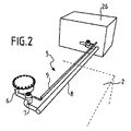
図3および4と関連して、一実施形態による気相ガス収集回路5の構造が、より具体的に観察される。第1および第2のパイプ8、9は、三方向コネクタ7と貨物室26との間で相互に平行に延設される。具体的には、有利には、コンプレッサ10、15、熱交換器13、膨張デバイス20、および相分離器19等の大部分のガス処理機器は、貨物室26内で再編成される。
In connection with FIGS. 3 and 4, the structure of the gas phase gas collection circuit 5 according to one embodiment is observed more specifically. The first and
第1および第2のパイプ8、9は、異なるガス通路断面を有し、第2のパイプ9のガス通路断面は、第1のパイプ8のものよりも小さい。第1のパイプ8および第2のパイプ9のガス通路断面の寸法は、それぞれ、その個別の使用事例に関してそれを通過する傾向にあるガス流率の関数として、およびガスの加熱を限定するように判定される。
The first and
パイプ内で循環するガスの加熱は、2つの対立する現象に依存する。一方では、パイプ内で循環するガスの加熱は、パイプの外部と内部との間で起こる熱伝達に依存する。これらの熱伝達の強度は、パイプの断熱特性に明白に依存するが、また、パイプ内のガスの滞留時間に依存し、その結果、管の流率および断面に依存する。具体的には、等しい流率に関して、ガスは、より大きい断面のパイプ内でより長い時間を費やし、その結果、より加熱された状態になる。他方では、パイプ内で循環するガスの加熱はまた、同一の流率に関して、パイプの断面が減少すると、流体の加熱の増加につながる、粘性消散の現象に依存する。したがって、所与の流率に関して、ガスの加熱が限定されることを可能にする、ガス通路断面の最適な寸法が存在する。 The heating of the gas circulating in the pipe depends on two opposing phenomena. On the one hand, the heating of the gas circulating in the pipe depends on the heat transfer that occurs between the outside and the inside of the pipe. The strength of these heat transfers clearly depends on the adiabatic properties of the pipe, but also on the residence time of the gas in the pipe, and thus on the flow rate and cross section of the pipe. Specifically, for equal flow rates, the gas spends a longer time in a pipe with a larger cross section, resulting in a more heated state. On the other hand, the heating of the gas circulating in the pipe also depends on the phenomenon of viscous dissipation, which leads to an increase in the heating of the fluid as the cross section of the pipe decreases for the same flow rate. Therefore, there are optimal dimensions of the gas passage cross section that allow limited heating of the gas for a given flow rate.
第1のパイプ8の断面は、タンク2と、タンクの装填または排出中に使用される傾向にある装填/排出ターミナルとの間の気相ガス移送の速度の関数として定寸される。実施例として、メタンタンカのタンクの装填または排出に関して、第1のパイプ8を通して生成される傾向にある気相ガス移送速度は、約12,000〜14,000m3/時である。したがって、そのような流率に関して、第1のパイプ8の断面は、典型的には、300〜600mmの直径を有する。 The cross section of the first pipe 8 is sized as a function of the rate of gas phase gas transfer between the tank 2 and the loading / unloading terminal that tends to be used during loading or unloading of the tank. As an example, for loading or unloading a tank of methane tankers, the gas phase gas transfer rate that tends to be produced through the first pipe 8 is about 12,000 to 14,000 m 3 / hour. Therefore, with respect to such flow rates, the cross section of the first pipe 8 typically has a diameter of 300-600 mm.
第2のパイプ9の断面は、その一部に関して、設備1のガス消費部材23、24、25に供給するために使用される傾向にある平均流率の関数として定寸される。実施例として、船舶を推進させる傾向にあるME−GIタイプのモータのガス給送に関して、第2のパイプ9を通して生成される傾向にある平均気相ガス移送速度は、約4,700m3/時である。したがって、そのような流率に関して、第2のパイプ9の断面は、典型的には、50〜200mmの直径を有する。
The cross section of the
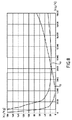
図8の曲線aおよびbは、それぞれ、流率の関数としての第1のパイプ8および第2のパイプ9内で循環するガスの加熱を表す。図8は、8,000Kg/時よりも低い流率に関して、ガスの加熱が第1のパイプ8内よりも第2のパイプ9内でより低い一方、8,000Kg/時を上回る流率に関して、ガスの加熱が第2のパイプ9内よりも第1のパイプ8内でより低いことを示す。したがって、実施例として、およそ4,000kg/時の流率では、第2のパイプ9内で循環するガスの加熱は、3℃よりもわずかに低い一方、第2のパイプ9内で循環するガスの加熱は、約15℃である。例えば、高流率のガスが戻りパイプ22を通して循環する状況に対応する、2,000kg/時のより低い流率では、第2のパイプ9内で循環するガスの加熱は、6℃よりもわずかに低い一方、第2のパイプ9内で循環するガスの加熱は、約30℃である。
Curves a and b in FIG. 8 represent heating of the gas circulating in the first and
有利には、三方向コネクタ7は、それを通して吸入口パイプ7が通過する、タンク2の開口に近接して配置される。言い換えると、三方向コネクタ7は、タンク壁内に作製される開口から、20メートルを下回る、有利には10メートルを下回る、好ましくは5メートルを下回る距離において配置される。したがって、気相ガスがタンク2から抽出されると事実上すぐに、それを通してガスが通過するパイプ8、9は、その流率の関数として最適化された断面を有する。これはまた、ガスの加熱を最小限にすることに寄与する。
Advantageously, the three-way connector 7 is located close to the opening of the tank 2 through which the inlet pipe 7 passes. In other words, the three-way connector 7 is located at a distance of less than 20 meters, preferably less than 10 meters, preferably less than 5 meters from the opening made in the tank wall. Thus,
さらに、図3に示される実施形態では、第1のパイプ8および第2のパイプ9は、それぞれ、四方向コネクタ27を介して、コンプレッサ10および熱交換器12に接続されることが観察される。四方向コネクタ27は、第1のパイプ8または第2のパイプ9内で循環する気相ガスを、ガス貯蔵ターミナルに接続されるように意図されるマニホールドに戻されるためにコンプレッサ10か、またはガス消費部材に部分的に運搬され、熱交換器11の第2のチャネルに部分的に戻されるために熱交換器11かのいずれかに選択的に運搬することが可能である。示される実施形態では、四方向コネクタ27は、三方向弁28によって構成され、これは、Y形結合具に接続され、その2つのアームは、それぞれ、弁29、30を具備する熱交換器12およびコンプレッサ10につながる。
Further, in the embodiment shown in FIG. 3, it is observed that the first pipe 8 and the
したがって、ある具体的使用事例では、第1のパイプ8から熱交換器12に気相ガスを運搬することもまた、可能である。
Therefore, in certain specific use cases, it is also possible to carry the gas phase gas from the first pipe 8 to the
そのようなガス循環は、以下の具体的使用事例において特に有用であり得る。
・タンク2の装填後の24〜48時間において。具体的には、本場合では、タンク2内の自然気化度は、平衡状態における自然気化度の約180%の値に到達し得る。本場合では、タンク2内に収集される気相ガスは、大量のガスを再液化するように、比較的に高い流率において、第1のパイプ8を通して熱交換器12に運搬され得る。
・タンク2内の自然気化度が、平衡状態における自然気化度を顕著に上回る全ての他の状況下、すなわち、荒天条件、長い周期の停止後に荒れた海に出ること、タンクの部分的充填とともに穏やかな海に出ること。
・可能な限り迅速にタンク2を排出するために、気相ガスを高流率においてガス消費部材23、24、25に運搬する等、ある損傷、特に、火災の条件下。
Such gas circulation can be particularly useful in the following specific use cases.
-In 24-48 hours after loading tank 2. Specifically, in this case, the degree of natural vaporization in the tank 2 can reach a value of about 180% of the degree of natural vaporization in the equilibrium state. In this case, the gas phase gas collected in the tank 2 can be transported to the
-With all other conditions in which the degree of natural vaporization in tank 2 significantly exceeds the degree of natural vaporization in equilibrium, namely stormy weather conditions, going out into rough seas after a long cycle stop, and partial filling of the tank. Go out to the calm sea.
-Some damage, especially under fire conditions, such as transporting the vapor phase gas to the
さらに、ある実施形態によると、タンク2から抽出された気相ガスは、ガス消費部材23、24、25の需要の関数において、第1のパイプ8または第2のパイプのいずれかを通して熱交換器12に運搬される。そのために、ガス消費部材23、24、25の設定流率が、判定された閾値と比較され、設定流率が判定された閾値を上回るかまたはそれに等しいとき、気相ガスは、第1のパイプを通して運搬される一方、設定流率が判定された閾値よりも低いとき、気相ガスは、第2のパイプを通して運搬される。
Further, according to one embodiment, the gas phase gas extracted from the tank 2 is a heat exchanger through either the first pipe 8 or the second pipe in a function of the demand of the
設定流率は、エネルギー増加が第1のパイプ8および第2のパイプ9内のガス循環に関して等しい流率にほぼ対応する。したがって、実施例として、図8の曲線aおよびbに対応する寸法および断熱特徴を有する第1および第2のパイプ8、9に関して、判定された閾値は、6,600〜10,000kg/時、例えば、約8,000kg/時である。
The set flow rate corresponds approximately to a flow rate in which the energy increase is equal for gas circulation in the first pipe 8 and the
図4に示されるように、設備1は、図4では3つである、複数のタンク2を備え得る。したがって、各タンク2は、タンク2の上壁内に作製される開口を通過し、タンク2のガス状ヘッドスペース内に出現する、吸入口パイプ6を備える。吸入口パイプ6はそれぞれ、三方向コネクタ7を介して、一方では、第1のパイプ8に接続され、他方では、第2のパイプ9に接続される。したがって、タンク6のガス状ヘッドスペースは、一方では、第1のパイプ8に、他方では、第2のパイプ9に直列に接続される。
As shown in FIG. 4, the
図5と関連して、一実施形態による第1のパイプ8および第2のパイプ9の詳細な構造もまた、観察される。第1および第2のパイプ8、9はそれぞれ、中間断熱空間8c、9cによって相互に分離される、2つの円筒形かつ同心円壁8a、8b:9a、9bを備えるジャケット付き管によって形成される。2つの壁8a、8b:9a、9bは、例えば、ステンレス鋼から作製される。
In connection with FIG. 5, the detailed structure of the first pipe 8 and the
第1のパイプ8の中間断熱空間8cは、断熱材料、例えば、ポリマーフォームまたはグラスウールを用いて裏打ちされる。第2のパイプ9の中間断熱空間9cは、真空下に置かれ、これは、優れた断熱特性を取得することに寄与する。
The
第1および第2のパイプ8、9は、有利には、気相ガス流がそれを通過するかどうかに応じて、その収縮および膨張を可能にするように、縦方向に沿ってそれらに可撓性を与える補償デバイスを有する。これを行うために、第1のパイプ8は、補償ループ31、すなわち、90°屈曲部を使用するU形形態を有する。そのような補償デバイスは、嵩張り、進行時間を延長させることに寄与し、その結果、ガスの加熱を増加させるが、これは、比較的に高価である。第2のパイプ9は、他方では、事実上その全長にわたって直線である。したがって、その膨張および収縮を可能にするために、第2のパイプ9の内壁9bは、ガセット区域32を一定に有する。
The first and
図5と関連して、有利な実施形態によると、第1および第2のパイプ8、9のそれぞれのガス通路断面の直径は、可変であり、本直径は、貨物室26に接近するにつれて増加し、吸入口パイプ6のうちの1つへのパイプの各接続において段階的に増加することが観察される。
In connection with FIG. 5, according to an advantageous embodiment, the diameter of each gas aisle cross section of the first and
言い換えると、第1および第2のパイプ8、9の断面は、それぞれ、貨物室26から最も遠いタンク2と第2の隣接するタンクとの間に延設される第1の部分において第1の直径d81、d91を有し、第2のタンクと第3の隣接するタンクとの間の第2の部分において第2の直径d82、d92を有し、第3のタンクと貨物室26との間の第3の部分において第3の直径d83、d93を有し、上記に言及される直径は、以下の不等式に対応する。
d91<d92<d93<<d81<d82<d83
In other words, the cross sections of the first and
d9 1 <d9 2 <d9 3 << d8 1 <d8 2 <d8 3
そのような配列は、第1および第2のパイプ8、9内のガス流の増加を考慮し、それらが他の吸入口パイプ6に接続されるとき、可能な限り密接にパイプ8、9の断面を定寸することを可能にする。これはまた、第1および第2のパイプ8、9内のガスの加熱を限定することに寄与する。
Such an arrangement takes into account the increase in gas flow in the first and
図6は、代替実施形態による、設備1を示す。本実施形態は、設備1がタンク2毎に第2のパイプ9、9'、9"を備える点において、図4および5の実施形態とは異なる。第2のパイプ9、9'、9"は、それぞれ、吸入口パイプ6のうちの1つから熱交換器12の第1のチャネル13の入口13aに気相ガスを運搬することが可能である。言い換えると、吸入口パイプ6はそれぞれ、三方向コネクタ7を介して第1のパイプ8および第2のパイプ9、9'、9"のそれぞれに接続される。そのような配列は、タンク2と熱交換器12との間でガスを運搬するために、熱交換器12に運搬されるべき気相ガス流がタンク2のうちの1つのみに由来するか、またはタンク2の全てに由来するかを問わず、ガスが、その寸法がそれを通過する傾向にあるガス流率の関数として最適化されるパイプ9、9'、9"内で循環する点において有利である。
FIG. 6 shows
図7は、液化天然ガス等の可燃性ガスを装填/抜取し、船舶41と浮遊設備または陸上設備(図示せず)との間のインターフェースを形成するための移送システム40を示す。船舶41は、上記に説明されるように、ガス消費部材に可燃性ガスを給送し、該可燃性ガスを液化するための設備を具備する。実施例として、液密および断熱タンク(図示せず)は、略角柱形態であり、船舶の二重船体内に搭載される。
FIG. 7 shows a
製品移送は、42と表される浸漬極低温ラインによって確実にされる。船舶41と浮遊設備または陸上設備との間のインターフェースを形成する移送システム40は、貯蔵/取扱ガントリ44を支える少なくとも1つのプラットフォーム43と、浸漬極低温ライン42を可撓性移送パイプ46に接続することを可能にする全ての機器を取り込むための主要プラットフォーム45とを備える。各可撓性移送パイプ46は、接続モジュール48を通して船舶のマニホールド47に接続されるように意図される。船舶のマニホールド47は、液化ガスの貨物をタンクから、またはそれに移送するために、船舶41の上側デッキ上に配列される装填/抜取パイプラインを用いてタンクに接続される。
Product transfer is ensured by an immersion cryogenic line represented by 42. The
ガントリ44の主な機能は、クレーンおよびウインチを用いて、移送部分、すなわち、各接続モジュール48および可撓性移送パイプ46の可動端の取扱および貯蔵を可能にすることである。 The main function of the gantry 44 is to use a crane and winch to allow the handling and storage of transfer parts, i.e., the movable ends of each connection module 48 and flexible transfer pipe 46.
ある実施形態によると、移送システムは、3つの平行な可撓性移送パイプ46を備え、そのうちの2つは、浮遊設備または陸上設備と船舶との間で液化天然ガスを移送することを可能にする一方、第3の移送パイプは、船舶のタンクのガス状ヘッドスペース内の圧力を均衡させるために、ガスを移送することを可能にする。 According to one embodiment, the transfer system comprises three parallel flexible transfer pipes 46, two of which allow the transfer of liquefied natural gas between floating or land equipment and the ship. On the other hand, a third transfer pipe allows the transfer of gas to balance the pressure in the gaseous headspace of the ship's tank.
液化ガスの移送のために必要な圧力を生成するために、船舶41内のオンボードポンプが、使用される、および/または、ポンプが、陸上設備内に設置される、および/または、ポンプが、移送システム40に嵌合される。
An onboard pump in
本発明は、いくつかの特定の実施形態と関連して説明されたが、これは、それに全く限定されず、これらが本発明の範囲内に該当する場合、説明される手段の全ての技術的均等物およびその組み合わせを備えることが明白である。 The present invention has been described in connection with some particular embodiments, but is not limited thereto, and where these fall within the scope of the invention, all technical means of the described means. It is clear that the equivalents and combinations thereof are provided.
動詞「〜を備える」または「〜を含有する」または「〜を含む」およびその活用形の使用は、請求項に記載されるもの以外の要素またはステップの存在を除外しない。 The use of the verbs "with" or "contains" or "contains" and their conjugations does not preclude the existence of elements or steps other than those set forth in the claims.
したがって、本技術のいくつかの非限定的実施形態に従って実装される方法および設備は、付番された付記において提示される、以下のように表されることができる。 Therefore, methods and equipment implemented according to some non-limiting embodiments of the present art can be expressed as follows, as presented in the numbered appendices.
付記1.ガス処理プロセスであって、
液気二相平衡状態におけるガスを用いて充填される内部空間を備える、漏出防止性かつ断熱性のタンク(2)を提供することと、
タンク(2)内に収集された気相ガス流から冷却されるべき流体に冷温を伝達するように意図される熱交換器(12)を提供することであって、熱交換器(12)は、それぞれ、入口(13a、14a)および出口(13b、14b)を有する、第1のチャネルおよび第2のチャネル(13、14)と、第2のチャネル(14)から第1のチャネル(13)に熱を伝達するための熱交換壁とを備える、ことと、
タンク(2)装填動作中、タンク(2)の壁内に作製される開口を通過し、タンクの内部空間内に出現する吸入口パイプ(6)を介して、タンク(2)から気相ガスを抽出し、これを第1のパイプ(8)を通して、ガス貯蔵ターミナルに接続されるマニホールド(11、47)に運搬することと、
タンク利用動作中、吸入口パイプ(6)を介して、タンク(2)から気相ガスを抽出し、第2のパイプ(9)を通して、これを熱交換器(12)に運搬することであって、該第2のパイプは、断熱性であり、第1のパイプ(8)のものよりも小さいガス通路断面を有する、ことと
を含む、ガス処理プロセス。
To provide a leak-proof and heat-insulating tank (2) having an internal space filled with gas in a liquid-liquid two-phase equilibrium state.
To provide a heat exchanger (12) intended to transfer cold temperature to a fluid to be cooled from a gas phase gas stream collected in a tank (2), the heat exchanger (12). A first channel and a second channel (13, 14) having an inlet (13a, 14a) and an outlet (13b, 14b), respectively, and a second channel (14) to a first channel (13). To have a heat exchange wall to transfer heat to
During the loading operation of the tank (2), the gas phase gas from the tank (2) passes through the opening formed in the wall of the tank (2) and passes through the suction port pipe (6) that appears in the internal space of the tank. Is extracted and transported to the manifolds (11, 47) connected to the gas storage terminal through the first pipe (8).
During the tank utilization operation, the gas phase gas is extracted from the tank (2) via the suction port pipe (6) and transported to the heat exchanger (12) through the second pipe (9). The gas treatment process, wherein the second pipe is heat insulating and has a smaller gas passage cross section than that of the first pipe (8).
付記2.コンプレッサ(15)を提供することであって、該コンプレッサは、熱交換器(12)内の加熱されたガス流を圧縮するように、熱交換器(12)の第1のチャネル(13)の出口(13b)に上流で接続され、ガス流の第1の部分をガス消費部材(23、24、25)に運搬し、ガス流の第2の部分を冷却するためにガス流の第2の部分を熱交換器(12)の第2のチャネル(14)の入口(14a)に運搬することが可能な三方向コネクタ(17、18)に下流で接続される、ことと、
熱交換器(12)の第2のチャネル(14)の出口(14b)に上流で接続され、タンク(2)につながる戻り回路(21)に下流で接続される、膨張デバイス(20)を提供することであって、膨張デバイス(20)は、これを液化するように熱交換器(12)の第2のチャネル(14)に由来するガス流の第2の部分を減圧するように配
列される、ことと、
タンク利用動作中にガス消費部材(23、24、25)の設定流率を判定することと、
設定流率を判定された閾値と比較することと、
設定流率が、判定された閾値を上回るかまたはそれに等しいとき、吸入口パイプ(6)を介してタンク(2)から気相ガスを抽出し、これを第1のパイプ(8)を通して熱交換器(12)に運搬することと、
設定流率が、判定された閾値をよりも低いとき、吸入口パイプ(6)を介してタンク(2)から気相ガスを抽出し、これを第2のパイプ(9)を通して熱交換器(12)に運搬することと
をさらに含む、付記1に記載のガス処理プロセス。
Appendix 2. To provide a compressor (15), the compressor of the first channel (13) of the heat exchanger (12) so as to compress the heated gas stream in the heat exchanger (12). Connected upstream to the outlet (13b), the first portion of the gas stream is carried to the gas consuming members (23, 24, 25) and the second portion of the gas stream is cooled to cool the second portion of the gas stream. It is connected downstream to a three-way connector (17, 18) capable of transporting the portion to the inlet (14a) of the second channel (14) of the heat exchanger (12).
Provided is an expansion device (20) connected upstream to the outlet (14b) of the second channel (14) of the heat exchanger (12) and downstream to the return circuit (21) leading to the tank (2). The expansion device (20) is arranged to depressurize the second portion of the gas stream from the second channel (14) of the heat exchanger (12) to liquefy it. And that
Determining the set flow rate of gas consuming members (23, 24, 25) during tank utilization operation
Comparing the set flow rate with the determined threshold and
When the set flow rate is above or equal to the determined threshold, gas phase gas is extracted from the tank (2) via the inlet pipe (6) and heat exchanged through the first pipe (8). To carry it to the vessel (12) and
When the set flow rate is lower than the determined threshold, gas phase gas is extracted from the tank (2) via the suction port pipe (6) and passed through the second pipe (9) to the heat exchanger ( The gas treatment process according to
付記3.ガス貯蔵および処理設備(1)であって、
液気二相平衡状態におけるガスを用いて充填されるように意図される内部空間を備える、漏出防止性かつ断熱性のタンク(2)と、
タンク(2)内に収集された気相ガス流から冷却されるべき流体に冷温を伝達するように意図される熱交換器(12)であって、該熱交換器(12)は、各々が入口(13a、14a)および出口(13b、14b)を有する第1のチャネルおよび第2のチャネル(13、14)と、第2のチャネル(14)から第1のチャネル(13)に熱を伝達するための熱交換壁とを備える、熱交換器(12)と、
気相ガス収集回路(5)であって、該気相ガス収集回路(5)は、
タンク(2)内の気相ガスを収集するように配列される吸入口パイプ(6)であって、該吸入口パイプは、タンク(2)の壁内に作製される開口を通過し、タンクの内部空間内に出現する、吸入口パイプ(6)と、
タンク(2)の装填中、吸入口パイプ(6)からガス貯蔵ターミナルに接続されるように意図されるマニホールド(11)に気相ガスを運搬するように配列される第1のパイプ(8)と、
吸入口パイプ(6)から交換器(12)の第1のチャネル(13)の入口(13a)に気相ガスを運搬するように配列される第2のパイプ(9)であって、該第2のパイプ(9)は、断熱性であり、第1のパイプ(8)のものよりも小さいガス通路断面を有する、第2のパイプ(9)と、
を備える、気相ガス収集回路(5)と
を備える、設備(1)。
Appendix 3. Gas storage and processing equipment (1)
A leak-proof and heat-insulating tank (2) with an internal space intended to be filled with gas in a liquid-liquid two-phase equilibrium state.
A heat exchanger (12) intended to transfer cold temperature from a gas phase gas stream collected in a tank (2) to a fluid to be cooled, each of which is a heat exchanger (12). Heat transfer from the first channel (13, 14) having inlets (13a, 14a) and outlets (13b, 14b) and from the second channel (14) to the first channel (13). A heat exchanger (12) with a heat exchange wall for the purpose of
The gas phase gas collection circuit (5) is a gas phase gas collection circuit (5).
A suction port pipe (6) arranged to collect the gas phase gas in the tank (2), and the suction port pipe passes through an opening made in the wall of the tank (2) and passes through the tank. The suction port pipe (6) that appears in the internal space of
A first pipe (8) arranged to carry gas phase gas from a suction pipe (6) to a manifold (11) intended to be connected to a gas storage terminal during loading of the tank (2). When,
A second pipe (9) arranged to carry gas phase gas from the suction port pipe (6) to the inlet (13a) of the first channel (13) of the exchanger (12). The second pipe (9) and the second pipe (9) are insulating and have a smaller gas passage cross section than that of the first pipe (8).
Equipment (1), including a gas phase gas collection circuit (5).
付記4.吸入口パイプ(6)は、吸入口パイプ(6)を介して収集された気相ガスを第1のパイプ(8)または第2のパイプ(9)のいずれかに選択的に運搬することが可能な三方向コネクタ(7)を介して、一方では、第1のパイプ(8)に接続され、他方では、第2のパイプ(9)に接続される、付記3に記載の設備(1)。 Appendix 4. The suction port pipe (6) can selectively carry the gas phase gas collected through the suction port pipe (6) to either the first pipe (8) or the second pipe (9). The equipment (1) according to Appendix 3, which, on the one hand, is connected to the first pipe (8) and, on the other hand, to the second pipe (9) via a possible three-way connector (7). ..
付記5.三方向コネクタ(7)は、タンク壁内に作製される開口から、20メートルを下回る、有利には10メートルを下回る、好ましくは5メートルを下回る距離において配置される、付記4に記載の設備(1)。 Appendix 5. The equipment according to Appendix 4, wherein the three-way connector (7) is located at a distance of less than 20 meters, preferably less than 10 meters, preferably less than 5 meters from an opening made in the tank wall. 1).
付記6.第1のパイプ(8)に接続され、第1のパイプ(8)を通して気相ガスを吸引し、これをマニホールド(11)に送達するように配列される、コンプレッサ(10)をも備える、付記3−5のうちのいずれか1項に記載の設備(1)。 Appendix 6. Also comprising a compressor (10), which is connected to a first pipe (8) and arranged to draw gas phase gas through the first pipe (8) and deliver it to the manifold (11), appendix. Equipment (1) according to any one of 3-5.
付記7.貨物室(26)を備え、熱交換器(12)およびコンプレッサ(11)は、貨物室(26)内に格納され、第1のパイプ(8)および第2のパイプ(9)は、吸入口パイプ(6)と貨物室(26)との間で相互に平行に延設される、付記6に記載の設備(1)。 Appendix 7. A cargo compartment (26) is provided, the heat exchanger (12) and the compressor (11) are housed in the cargo compartment (26), and the first pipe (8) and the second pipe (9) are suction ports. The equipment (1) according to Appendix 6, which extends parallel to each other between the pipe (6) and the cargo hold (26).
付記8.第1のパイプ(8)および第2のパイプ(9)の各々は、第1のパイプ(8)または第2のパイプ(9)内で循環する気相ガスをコンプレッサ(11)または熱交換器(12)に選択的に運搬することが可能な四方向コネクタ(27)を介して、コンプレッサ(11)および熱交換器(12)に接続される、付記7に記載の設備(1)。 Appendix 8. Each of the first pipe (8) and the second pipe (9) compresses the gas phase gas circulating in the first pipe (8) or the second pipe (9) into a compressor (11) or a heat exchanger. The equipment (1) according to Appendix 7, which is connected to the compressor (11) and the heat exchanger (12) via a four-way connector (27) that can be selectively transported to (12).
付記9.複数の漏出防止性かつ断熱性のタンク(2)を備え、該複数の漏出防止性かつ断熱性のタンクの各々は、液気二相平衡状態におけるガスを用いて充填されるように意図される内部空間を備え、気相ガス収集回路(5)は、該タンク(2)毎に、該タンク(2)の壁内に作製される開口を通過し、該タンク(2)の内部空間内に出現する、吸入口パイプ(6)を備える、付記3−8のうちのいずれか1項に記載の設備(1)。
付記10.各吸入口パイプ(6)は、吸入口パイプ(6)を介して収集された気相ガスを第1のパイプ(8)または第2のパイプ(9)のいずれかに選択的に運搬することが可能な三方向コネクタ(7)を介して、一方では、第1のパイプ(8)に接続され、他方では、第2のパイプ(9)に接続される、付記9に記載の設備(1)。
付記11.第2のパイプ(9)は、可変直径のガス通路断面を有し、該第2のパイプ(9)のガス通路断面の直径は、熱交換器(12)の第1のチャネル(13)の方向において増加し、吸入口パイプ(6)のうちの1つへの第2のパイプ(9)の各接続において段階的に増加する、付記10に記載の設備(1)。
Appendix 11. The second pipe (9) has a variable diameter gas passage cross section, and the diameter of the gas passage cross section of the second pipe (9) is that of the first channel (13) of the heat exchanger (12). The equipment (1) according to
付記12.複数の第2のパイプ(9、9'、9")をも備え、該複数の第2のパイプの各々は、吸入口パイプ(6)のうちの1つから熱交換器(12)の第1のチャネル(13)の入口(13a)に気相ガスを運搬することが可能であり、第2のパイプ(9、9'、9")の各々は、第1のパイプ(8)のものよりも小さいガス通路断面を有し、各吸入口パイプ(6)は、該吸入口パイプ(6)を介して収集された気相ガスを第1のパイプ(8)または第2のパイプ(9)のうちの1つのいずれかに選択的に運搬することが可能な三方向コネクタ(7)によって、一方では、第1のパイプ(8)に接続され、他方では、第2のパイプ(9、9'、9")のうちの1つに接続される、付記10に記載の設備(1)。
付記13.第1のパイプ(8)は、その直径が300〜600mmであるガス通路断面を有し、第2のパイプ(9)は、その直径が50〜200mmであるガス通路断面を有する、付記3−12のうちのいずれか1項に記載の設備(1)。 Appendix 13. The first pipe (8) has a gas passage cross section having a diameter of 300 to 600 mm, and the second pipe (9) has a gas passage cross section having a diameter of 50 to 200 mm, Appendix 3-. The equipment (1) according to any one of 12.
付記14.第1および/または第2のパイプ(8、9)は、内壁(8b、9b)および外壁(8a、9a)を備えるジャケット付き管によって形成され、該内壁および外壁は、同心円状であり、中間断熱空間(8c、9c)によって相互に分離される、付記3−13のうちのいずれか1項に記載の設備(1)。
付記15.第2のパイプ(9)の中間断熱空間(9c)は、真空下にある、付記14に記載の設備(1)。
付記16.第1のパイプ(8)の中間断熱空間(8c)は、断熱材料を用いて裏打ちされる、付記14または15に記載の設備(1)。
Appendix 16. The equipment (1) according to
付記17.コンプレッサ(15)であって、該コンプレッサは、熱交換器(12)内の加熱されたガス流を圧縮するように、熱交換器(12)の第1のチャネル(13)の出口(13b)に上流で接続され、ガス流の第1の部分をガス消費部材(23、24、25)に運搬し、ガス流の第2の部分を冷却するためにガス流の第2の部分を熱交換器(12)の第2のチャネル(14)の入口(14a)に運搬することが可能な三方向コネクタ(17、18)に下流で接続される、コンプレッサ(15)と、
熱交換器(12)の第2のチャネル(14)の出口(14b)に上流で接続され、タンク(2)につながる戻り回路(21)に下流で接続される、膨張デバイス(20)であって、該膨張デバイスは、これを液化するように熱交換器(12)の第2のチャネル(14)に由来するガス流の第2の部分を減圧するように配列される、膨張デバイス(20)と
をも備える、付記3−16のうちのいずれか1項に記載の設備(1)。
An expansion device (20) connected upstream to the outlet (14b) of the second channel (14) of the heat exchanger (12) and downstream to the return circuit (21) leading to the tank (2). The expansion device (20) is arranged to depressurize a second portion of the gas stream from the second channel (14) of the heat exchanger (12) to liquefy it. ) And the equipment (1) according to any one of Appendix 3-16.
付記18.ガスを輸送するための船舶(40)であって、付記3−17のうちのいずれか1項に記載の設備(1)を備える、船舶。 Appendix 18. A ship (40) for transporting gas, which is provided with the equipment (1) according to any one of Appendix 3-17.
付記19.ガス移送システムであって、本システムは、付記16に記載の船舶(40)と、船舶の船体内に設置される本設備のタンクを浮遊ガス貯蔵ターミナルまたは陸上ガス貯蔵ターミナルに接続するように配列される、極低温移送パイプ(42、46)と、極低温移送パイプを通して、浮遊ガス貯蔵ターミナルまたは陸上ガス貯蔵ターミナルから、またはそれに、船舶のタンク(2)に、またはそれから液相ガス流を取り込むためのポンプとを備え、該移送システムは、マニホールド(11、47)をガス貯蔵ターミナルに接続し、ガス貯蔵および処理設備(1)とガス貯蔵ターミナルとの間の気相ガスの移送を可能にするように配列される、気相ガス移送パイプをも備える、移送システム。
付記20.ガスが、極低温移送パイプ(42、46)を通して、浮遊ガス貯蔵ターミナルまたは陸上ガス貯蔵ターミナルから、またはそれに、船舶のガス貯蔵および処理設備のタンクに、またはそれから伝導される、付記16に記載の船舶(40)において装填または排出するためのプロセス。
Claims (16)
液気二相平衡状態におけるガスを用いて充填される内部空間を備える、漏出防止性かつ断熱性のタンクを提供することと、
前記タンク内に収集された気相ガス流から冷却されるべき流体に冷温を伝達するように意図される熱交換器を提供することであって、前記熱交換器は、各々が入口および出口を有する第1のチャネルおよび第2のチャネルと、前記第2のチャネルから前記第1のチャネルに熱を伝達するための熱交換壁とを備える、ことと、
コンプレッサを提供することであって、前記コンプレッサは、前記熱交換器内で加熱されたガス流を圧縮するように、上流で前記熱交換器の第1のチャネルの出口に接続され、下流で三方向コネクタに接続され、前記三方向コネクタは、前記ガス流の第1の部分をガス消費部材に運搬し、前記ガス流の第2の部分を冷却するために前記ガス流の第2の部分を前記熱交換器の第2のチャネルの入口に運搬することが可能である、ことと、
膨張デバイスを提供することであって、前記膨張デバイスは、上流で前記熱交換器の第2のチャネルの出口に接続され、下流で戻り回路に接続され、前記戻り回路は前記タンクにつながり、前記膨張デバイスは、これを液化するように前記熱交換器の第2のチャネルに由来する前記ガス流の第2の部分を減圧するように配列される、ことと、
タンク装填動作中、前記タンクの壁内に作製される開口を通過し、前記タンクの内部空間内に出現する吸入口パイプを介して、前記タンクから気相ガスを抽出し、これを第1のパイプを通して、ガス貯蔵ターミナルに接続されるマニホールドに運搬することであって、前記第1のパイプは、一方では前記マニホールドに、他方では前記熱交換器に、選択的に接続される、ことと
を含み、
前記ガス処理プロセスは、
タンク利用動作中に前記ガス消費部材の設定流率を判定することと、
前記設定流率を判定された閾値と比較することと、
前記設定流率が、前記判定された閾値を上回るかまたは前記判定された閾値に等しいとき、前記吸入口パイプを介して前記タンクから気相ガスを抽出し、これを前記第1のパイプを通して前記熱交換器に運搬することと、
前記設定流率が、前記判定された閾値よりも低いとき、前記吸入口パイプを介して前記タンクから気相ガスを抽出し、これを第2のパイプを通して前記熱交換器に運搬することと
をさらに含む、ガス処理プロセス。 It ’s a gas treatment process,
To provide a leak-proof and adiabatic tank with an internal space filled with gas in a liquid-liquid two-phase equilibrium state.
To provide a heat exchanger intended to transfer cold temperature from a gas phase gas stream collected in the tank to a fluid to be cooled, the heat exchangers having inlets and outlets, respectively. It is provided with a first channel and a second channel having a heat exchange wall for transferring heat from the second channel to the first channel.
To provide a compressor, the compressor is connected upstream to the outlet of the first channel of the heat exchanger so as to compress a gas stream heated in the heat exchanger, and three downstream. Connected to a directional connector, the three-way connector transports a first portion of the gas stream to a gas consuming member and cools the second portion of the gas stream with a second portion of the gas stream. It can be transported to the inlet of the second channel of the heat exchanger, and
To provide an expansion device, the expansion device is connected upstream to the outlet of a second channel of the heat exchanger and downstream to a return circuit, the return circuit connecting to the tank, said The expansion device is arranged to depressurize a second portion of the gas stream from the second channel of the heat exchanger to liquefy it.
During the tank loading operation, the gas phase gas is extracted from the tank through the opening formed in the wall of the tank and the suction port pipe that appears in the internal space of the tank, and this is used as the first. Transporting through a pipe to a manifold connected to a gas storage terminal , wherein the first pipe is selectively connected to the manifold on the one hand and to the heat exchanger on the other hand.
Including
The gas treatment process
Judging the set flow rate of the gas consuming member during the tank utilization operation
Comparing the set flow rate with the determined threshold value
When the set flow rate exceeds the determined threshold value or is equal to the determined threshold value, gas phase gas is extracted from the tank via the suction port pipe, and this is passed through the first pipe. Transporting to a heat exchanger and
When the set flow rate is lower than the determined threshold value, the gas phase gas is extracted from the tank through the suction port pipe and transported to the heat exchanger through the second pipe. Further including gas treatment process.
液気二相平衡状態におけるガスを用いて充填されるように意図される内部空間を備える、漏出防止性かつ断熱性のタンクと、
前記タンク内に収集された気相ガス流から冷却されるべき流体に冷温を伝達するように意図される熱交換器であって、前記熱交換器は、各々が入口および出口を有する第1のチャネルおよび第2のチャネルと、前記第2のチャネルから前記第1のチャネルに熱を伝達するための熱交換壁とを備える、熱交換器と、
気相ガス収集回路であって、前記気相ガス収集回路は、
前記タンク内の気相ガスを収集するように配列される吸入口パイプであって、前記吸入口パイプは、前記タンクの壁内に作製される開口を通過し、前記タンクの内部空間内に出現する、吸入口パイプと、
前記タンクの装填中、前記吸入口パイプからガス貯蔵ターミナルに接続されるように意図されるマニホールドに気相ガスを運搬するように配列される第1のパイプと、
前記吸入口パイプから前記熱交換器の第1のチャネルの入口に気相ガスを運搬するように配列される第2のパイプであって、前記第2のパイプは、断熱性であり、前記第1のパイプのガス通路断面よりも小さいガス通路断面を有する、第2のパイプと、
前記第1のパイプに接続されるコンプレッサであって、前記コンプレッサは、前記第1のパイプを通して気相ガスを吸引し、これを前記マニホールドに送達するように配列される、コンプレッサと、
貨物室であって、前記貨物室内に前記熱交換器および前記コンプレッサが格納され、前記第1のパイプおよび前記第2のパイプは、前記吸入口パイプと前記貨物室との間で相互に平行に延設され、前記第1のパイプおよび前記第2のパイプの各々は、前記第1のパイプまたは前記第2のパイプ内で循環する気相ガスを前記コンプレッサまたは前記熱交換器に選択的に運搬することが可能な四方向コネクタを介して、前記コンプレッサおよび前記熱交換器に接続される、貨物室と
を備える、気相ガス収集回路と
を備える、設備。 Gas storage and processing equipment
A leak-proof and adiabatic tank with an internal space intended to be filled with gas in a liquid-liquid two-phase equilibrium state.
A first heat exchanger intended to transfer cold temperature from a gas phase gas stream collected in the tank to a fluid to be cooled, the heat exchanger having an inlet and an outlet, respectively. A heat exchanger comprising a channel and a second channel and a heat exchange wall for transferring heat from the second channel to the first channel.
It is a gas phase gas collection circuit, and the gas phase gas collection circuit is
A suction port pipe arranged to collect the gas phase gas in the tank, the suction port pipe passes through an opening made in the wall of the tank and appears in the internal space of the tank. With the suction port pipe,
During loading of the tank, a first pipe arranged to carry gas phase gas from the inlet pipe to a manifold intended to be connected to the gas storage terminal.
A second pipe arranged to carry gas phase gas from the suction port pipe to the inlet of the first channel of the heat exchanger, the second pipe is heat insulating and said. has a smaller gas passage cross-section than the gas passage section of the first pipe, a second pipe,
A compressor connected to the first pipe, wherein the compressor is arranged to draw gas phase gas through the first pipe and deliver it to the manifold.
In the cargo compartment, the heat exchanger and the compressor are housed in the cargo compartment, and the first pipe and the second pipe are parallel to each other between the suction port pipe and the cargo compartment. Each of the first pipe and the second pipe, which is extended, selectively transports the gas phase gas circulating in the first pipe or the second pipe to the compressor or the heat exchanger. With a cargo compartment connected to the compressor and the heat exchanger via a four-way connector capable of
A facility equipped with a gas phase gas collection circuit.
膨張デバイスであって、前記膨張デバイスは、上流で前記熱交換器の第2のチャネルの出口に接続され、下流で戻り回路に接続され、前記戻り回路は、前記タンクにつながり、前記膨張デバイスは、これを液化するように前記熱交換器の第2のチャネルに由来する前記ガス流の第2の部分を減圧するように配列される、膨張デバイスと
をも備える、請求項2〜4のうちのいずれか1項に記載の設備。 A compressor, the compressor is to compress the heated gas flow in the heat exchanger, is connected to the outlet of the first channel of the heat exchanger upstream, the three-way connector downstream Connected, the three-way connector carries a first portion of the gas stream to a gas consuming member and heat exchanges the second portion of the gas stream to cool the second portion of the gas stream. With a compressor , which can be transported to the inlet of the second channel of the vessel,
A expansion device, said expansion device is connected to the outlet of the second channel of the heat exchanger upstream is connected to the circuit back downstream, the return circuit leads to the tank, the expansion device, which is arranged to the second portion of the gas stream from the second channel of the heat exchanger to liquefy vacuo, also includes an expander device, according to claim 2-4 Equipment described in any one of the items.
Applications Claiming Priority (1)
| Application Number | Priority Date | Filing Date | Title |
|---|---|---|---|
| PCT/US2016/031763 WO2017196310A1 (en) | 2016-05-11 | 2016-05-11 | Gas storage and treatment installation |
Publications (2)
| Publication Number | Publication Date |
|---|---|
| JP2019516917A JP2019516917A (en) | 2019-06-20 |
| JP6776370B2 true JP6776370B2 (en) | 2020-10-28 |
Family
ID=60267495
Family Applications (1)
| Application Number | Title | Priority Date | Filing Date |
|---|---|---|---|
| JP2018557373A Active JP6776370B2 (en) | 2016-05-11 | 2016-05-11 | Gas storage and processing equipment |
Country Status (6)
| Country | Link |
|---|---|
| EP (1) | EP3455545B1 (en) |
| JP (1) | JP6776370B2 (en) |
| KR (1) | KR101953507B1 (en) |
| CN (1) | CN109563967B (en) |
| ES (1) | ES2937024T3 (en) |
| WO (1) | WO2017196310A1 (en) |
Families Citing this family (2)
| Publication number | Priority date | Publication date | Assignee | Title |
|---|---|---|---|---|
| JP6595143B1 (en) * | 2019-07-03 | 2019-10-23 | 株式会社神戸製鋼所 | Compressor unit and control method of compressor unit |
| FR3100055B1 (en) * | 2019-08-19 | 2021-07-23 | Gaztransport Et Technigaz | Gas treatment system contained in a tank for storing and / or transporting gas in the liquid state and in the gaseous state fitted to a ship |
Family Cites Families (14)
| Publication number | Priority date | Publication date | Assignee | Title |
|---|---|---|---|---|
| JP2002295799A (en) * | 2001-04-03 | 2002-10-09 | Kobe Steel Ltd | Method and system for treating liquefied natural gas and nitrogen |
| US6692192B2 (en) * | 2002-05-03 | 2004-02-17 | Single Buoy Moorings Inc. | Spread moored midship hydrocarbon loading and offloading system |
| FR2852590B1 (en) * | 2003-03-20 | 2005-06-17 | Snecma Moteurs | POWER SUPPLYING A GAS TERMINAL FROM A SHIP TRANSPORTING LIQUEFIED GAS |
| JP2005155668A (en) * | 2003-11-20 | 2005-06-16 | Jgc Corp | Cryogenic liquid shipping piping line |
| AU2004229037B2 (en) * | 2003-11-20 | 2010-05-20 | Itp | Pipeline for the transportation of liquefied natural gas |
| WO2012165865A2 (en) * | 2011-05-31 | 2012-12-06 | 대우조선해양 주식회사 | Cold heat recovery apparatus using an lng fuel, and liquefied gas carrier including same |
| KR101386543B1 (en) * | 2012-10-24 | 2014-04-18 | 대우조선해양 주식회사 | System for treating boil-off gas for a ship |
| SG11201504439YA (en) * | 2012-12-11 | 2015-07-30 | Daewoo Shipbuilding & Marine | Liquefied gas processing system for ship |
| KR101640765B1 (en) * | 2013-06-26 | 2016-07-19 | 대우조선해양 주식회사 | System and method for treating boil-off gas for a ship |
| CN203743842U (en) | 2014-03-27 | 2014-07-30 | 山西易高煤层气有限公司 | Recovery system of BOG (Boil Off Gas) of normal-pressure low-temperature LNG (Liquefied Natural Gas) storage tank |
| KR101635061B1 (en) * | 2014-04-18 | 2016-06-30 | 삼성중공업 주식회사 | Lng cargo handling system |
| WO2015178743A1 (en) * | 2014-05-23 | 2015-11-26 | 현대중공업 주식회사 | Liquefied gas treatment system |
| KR101857325B1 (en) * | 2014-05-23 | 2018-05-11 | 현대중공업 주식회사 | A Treatment System of Liquefied Gas |
| JP6873116B2 (en) * | 2015-11-05 | 2021-05-19 | コリア シップビルディング アンド オフショア エンジニアリング カンパニー リミテッド | Gas treatment system and ships including it |
-
2016
- 2016-05-11 ES ES16901827T patent/ES2937024T3/en active Active
- 2016-05-11 CN CN201680087167.3A patent/CN109563967B/en active Active
- 2016-05-11 JP JP2018557373A patent/JP6776370B2/en active Active
- 2016-05-11 WO PCT/US2016/031763 patent/WO2017196310A1/en active Search and Examination
- 2016-05-11 EP EP16901827.2A patent/EP3455545B1/en active Active
- 2016-05-11 KR KR1020177036997A patent/KR101953507B1/en active IP Right Grant
Also Published As
| Publication number | Publication date |
|---|---|
| WO2017196310A1 (en) | 2017-11-16 |
| CN109563967B (en) | 2021-04-02 |
| ES2937024T3 (en) | 2023-03-23 |
| KR101953507B1 (en) | 2019-02-28 |
| EP3455545B1 (en) | 2022-11-09 |
| EP3455545A1 (en) | 2019-03-20 |
| KR20180029975A (en) | 2018-03-21 |
| CN109563967A (en) | 2019-04-02 |
| JP2019516917A (en) | 2019-06-20 |
| EP3455545A4 (en) | 2020-01-22 |
Similar Documents
| Publication | Publication Date | Title |
|---|---|---|
| US6089022A (en) | Regasification of liquefied natural gas (LNG) aboard a transport vessel | |
| US10006589B2 (en) | Method and system for storage and transport of liquefied petroleum gases | |
| CN107110427B (en) | Device and method for cooling liquefied gas | |
| US7517391B2 (en) | Method of bulk transport and storage of gas in a liquid medium | |
| KR20100015355A (en) | Apparatus and method for flowing compressed fluids into and out of containment | |
| JP6726201B2 (en) | Method for cooling liquefied gas | |
| WO2005071333A1 (en) | Method for re-liquefaction of boil-off gas | |
| JP6850305B2 (en) | Equipment for supplying flammable gas to gas consuming parts and for liquefying this flammable gas | |
| JP6934885B2 (en) | Evaporative gas reliquefaction device and evaporative gas reliquefaction method | |
| WO2015110443A2 (en) | Coastal liquefaction | |
| JP2019529218A (en) | Evaporative gas reliquefaction apparatus and evaporative gas reliquefaction method for ships | |
| JP6776370B2 (en) | Gas storage and processing equipment | |
| US20080184735A1 (en) | Refrigerant storage in lng production | |
| EP2749807A1 (en) | Fluid supply assemblage, a floating transportation vessel, method of assembling a fluid supply assemblage, and method of transferring a fluid | |
| CN112243479B (en) | Method and system for storage and transportation of liquefied petroleum gas | |
| KR101788752B1 (en) | BOG Re-liquefaction Apparatus and Method for Vessel | |
| EP2749806A1 (en) | Method of supplying a hydrocarbon load from a starting location to a destination | |
| KR20240032571A (en) | Carbon dioxide liquefaction system and ship having the same |
Legal Events
| Date | Code | Title | Description |
|---|---|---|---|
| A521 | Request for written amendment filed |
Free format text: JAPANESE INTERMEDIATE CODE: A523 Effective date: 20190108 |
|
| A621 | Written request for application examination |
Free format text: JAPANESE INTERMEDIATE CODE: A621 Effective date: 20190221 |
|
| A977 | Report on retrieval |
Free format text: JAPANESE INTERMEDIATE CODE: A971007 Effective date: 20200120 |
|
| A131 | Notification of reasons for refusal |
Free format text: JAPANESE INTERMEDIATE CODE: A131 Effective date: 20200123 |
|
| A601 | Written request for extension of time |
Free format text: JAPANESE INTERMEDIATE CODE: A601 Effective date: 20200420 |
|
| A601 | Written request for extension of time |
Free format text: JAPANESE INTERMEDIATE CODE: A601 Effective date: 20200421 |
|
| A521 | Request for written amendment filed |
Free format text: JAPANESE INTERMEDIATE CODE: A523 Effective date: 20200706 |
|
| TRDD | Decision of grant or rejection written | ||
| A01 | Written decision to grant a patent or to grant a registration (utility model) |
Free format text: JAPANESE INTERMEDIATE CODE: A01 Effective date: 20200909 |
|
| A61 | First payment of annual fees (during grant procedure) |
Free format text: JAPANESE INTERMEDIATE CODE: A61 Effective date: 20201007 |
|
| R150 | Certificate of patent or registration of utility model |
Ref document number: 6776370 Country of ref document: JP Free format text: JAPANESE INTERMEDIATE CODE: R150 |
|
| R250 | Receipt of annual fees |
Free format text: JAPANESE INTERMEDIATE CODE: R250 |