JP6776222B2 - Milking pump system and method - Google Patents
Milking pump system and method Download PDFInfo
- Publication number
- JP6776222B2 JP6776222B2 JP2017503552A JP2017503552A JP6776222B2 JP 6776222 B2 JP6776222 B2 JP 6776222B2 JP 2017503552 A JP2017503552 A JP 2017503552A JP 2017503552 A JP2017503552 A JP 2017503552A JP 6776222 B2 JP6776222 B2 JP 6776222B2
- Authority
- JP
- Japan
- Prior art keywords
- milk
- nipple
- breast
- chest
- pressure
- Prior art date
- Legal status (The legal status is an assumption and is not a legal conclusion. Google has not performed a legal analysis and makes no representation as to the accuracy of the status listed.)
- Active
Links
- 0 CCCC(C(CC1C)=C=CC([C@]23)[C@@](C)C2*3=C=C2CCC2)C1=C Chemical compound CCCC(C(CC1C)=C=CC([C@]23)[C@@](C)C2*3=C=C2CCC2)C1=C 0.000 description 1
Images


Classifications
-
- A—HUMAN NECESSITIES
- A61—MEDICAL OR VETERINARY SCIENCE; HYGIENE
- A61M—DEVICES FOR INTRODUCING MEDIA INTO, OR ONTO, THE BODY; DEVICES FOR TRANSDUCING BODY MEDIA OR FOR TAKING MEDIA FROM THE BODY; DEVICES FOR PRODUCING OR ENDING SLEEP OR STUPOR
- A61M1/00—Suction or pumping devices for medical purposes; Devices for carrying-off, for treatment of, or for carrying-over, body-liquids; Drainage systems
- A61M1/06—Milking pumps
-
- A—HUMAN NECESSITIES
- A61—MEDICAL OR VETERINARY SCIENCE; HYGIENE
- A61J—CONTAINERS SPECIALLY ADAPTED FOR MEDICAL OR PHARMACEUTICAL PURPOSES; DEVICES OR METHODS SPECIALLY ADAPTED FOR BRINGING PHARMACEUTICAL PRODUCTS INTO PARTICULAR PHYSICAL OR ADMINISTERING FORMS; DEVICES FOR ADMINISTERING FOOD OR MEDICINES ORALLY; BABY COMFORTERS; DEVICES FOR RECEIVING SPITTLE
- A61J13/00—Breast-nipple shields
-
- A—HUMAN NECESSITIES
- A61—MEDICAL OR VETERINARY SCIENCE; HYGIENE
- A61M—DEVICES FOR INTRODUCING MEDIA INTO, OR ONTO, THE BODY; DEVICES FOR TRANSDUCING BODY MEDIA OR FOR TAKING MEDIA FROM THE BODY; DEVICES FOR PRODUCING OR ENDING SLEEP OR STUPOR
- A61M1/00—Suction or pumping devices for medical purposes; Devices for carrying-off, for treatment of, or for carrying-over, body-liquids; Drainage systems
- A61M1/06—Milking pumps
- A61M1/062—Pump accessories
- A61M1/064—Suction cups
-
- A—HUMAN NECESSITIES
- A61—MEDICAL OR VETERINARY SCIENCE; HYGIENE
- A61M—DEVICES FOR INTRODUCING MEDIA INTO, OR ONTO, THE BODY; DEVICES FOR TRANSDUCING BODY MEDIA OR FOR TAKING MEDIA FROM THE BODY; DEVICES FOR PRODUCING OR ENDING SLEEP OR STUPOR
- A61M1/00—Suction or pumping devices for medical purposes; Devices for carrying-off, for treatment of, or for carrying-over, body-liquids; Drainage systems
- A61M1/06—Milking pumps
- A61M1/062—Pump accessories
- A61M1/067—Pump accessories with means for hands-free operation
-
- A—HUMAN NECESSITIES
- A61—MEDICAL OR VETERINARY SCIENCE; HYGIENE
- A61M—DEVICES FOR INTRODUCING MEDIA INTO, OR ONTO, THE BODY; DEVICES FOR TRANSDUCING BODY MEDIA OR FOR TAKING MEDIA FROM THE BODY; DEVICES FOR PRODUCING OR ENDING SLEEP OR STUPOR
- A61M1/00—Suction or pumping devices for medical purposes; Devices for carrying-off, for treatment of, or for carrying-over, body-liquids; Drainage systems
- A61M1/06—Milking pumps
- A61M1/069—Means for improving milking yield
- A61M1/0693—Means for improving milking yield with programmable or pre-programmed sucking patterns
- A61M1/06935—Means for improving milking yield with programmable or pre-programmed sucking patterns imitating the suckling of an infant
-
- A—HUMAN NECESSITIES
- A61—MEDICAL OR VETERINARY SCIENCE; HYGIENE
- A61M—DEVICES FOR INTRODUCING MEDIA INTO, OR ONTO, THE BODY; DEVICES FOR TRANSDUCING BODY MEDIA OR FOR TAKING MEDIA FROM THE BODY; DEVICES FOR PRODUCING OR ENDING SLEEP OR STUPOR
- A61M1/00—Suction or pumping devices for medical purposes; Devices for carrying-off, for treatment of, or for carrying-over, body-liquids; Drainage systems
- A61M1/06—Milking pumps
- A61M1/069—Means for improving milking yield
- A61M1/0697—Means for improving milking yield having means for massaging the breast
-
- A—HUMAN NECESSITIES
- A61—MEDICAL OR VETERINARY SCIENCE; HYGIENE
- A61M—DEVICES FOR INTRODUCING MEDIA INTO, OR ONTO, THE BODY; DEVICES FOR TRANSDUCING BODY MEDIA OR FOR TAKING MEDIA FROM THE BODY; DEVICES FOR PRODUCING OR ENDING SLEEP OR STUPOR
- A61M1/00—Suction or pumping devices for medical purposes; Devices for carrying-off, for treatment of, or for carrying-over, body-liquids; Drainage systems
- A61M1/71—Suction drainage systems
- A61M1/74—Suction control
-
- A—HUMAN NECESSITIES
- A61—MEDICAL OR VETERINARY SCIENCE; HYGIENE
- A61B—DIAGNOSIS; SURGERY; IDENTIFICATION
- A61B18/00—Surgical instruments, devices or methods for transferring non-mechanical forms of energy to or from the body
- A61B2018/00315—Surgical instruments, devices or methods for transferring non-mechanical forms of energy to or from the body for treatment of particular body parts
- A61B2018/00333—Breast
-
- A—HUMAN NECESSITIES
- A61—MEDICAL OR VETERINARY SCIENCE; HYGIENE
- A61M—DEVICES FOR INTRODUCING MEDIA INTO, OR ONTO, THE BODY; DEVICES FOR TRANSDUCING BODY MEDIA OR FOR TAKING MEDIA FROM THE BODY; DEVICES FOR PRODUCING OR ENDING SLEEP OR STUPOR
- A61M2205/00—General characteristics of the apparatus
- A61M2205/33—Controlling, regulating or measuring
- A61M2205/3331—Pressure; Flow
-
- A—HUMAN NECESSITIES
- A61—MEDICAL OR VETERINARY SCIENCE; HYGIENE
- A61M—DEVICES FOR INTRODUCING MEDIA INTO, OR ONTO, THE BODY; DEVICES FOR TRANSDUCING BODY MEDIA OR FOR TAKING MEDIA FROM THE BODY; DEVICES FOR PRODUCING OR ENDING SLEEP OR STUPOR
- A61M2210/00—Anatomical parts of the body
- A61M2210/10—Trunk
- A61M2210/1007—Breast; mammary
Description
本開示は、一般に、母乳を授乳期の母親の胸から収集するための携帯用のエネルギー効率の良い搾乳ポンプシステムおよび方法に関する。 The present disclosure generally relates to a portable energy efficient milking pump system and method for collecting breast milk from the breast of a lactating mother.
母乳栄養が、乳児にとって最適な栄養供給源であり、授乳期の母親にも健康的恩恵を提供すると考える女性が多くなるにつれ、さまざまな状況において授乳期の母親によって使用するための、ユーザにやさしく、静かで、個別的な、多用途である搾乳ポンプの解決策に対する必要性が増してきている。これは特に、8時間から10時間、またはそれ以上の間家から離れ、乳児が飲めるように母乳を搾り出す必要がある働く女性に特に当てはまるが、これはまた、母親が、長期間、家庭の私事から離れる多くの他の状況、たとえば買い物中、外食中、または他の活動に対する要求事項でもある。 User-friendly for use by lactating mothers in a variety of situations as more women believe that breastfeeding is the optimal source of nutrition for their babies and also provides health benefits to lactating mothers. There is an increasing need for quiet, personalized, versatile milking pump solutions. This is especially true for working women who have been away from home for 8 to 10 hours or more and need to squeeze their milk for their baby to drink, but this is also true for working women who have long-term home care. It is also a requirement for many other situations away from personal affairs, such as shopping, eating out, or other activities.
多様な搾乳ポンプが入手可能であるが、ほとんどが扱いにくく、煩雑なものであり、多くの部材および組立体を必要とし、持ち運びが難しい。手動で駆動される手動用ポンプのさまざまなものは、使用するのが面倒であり、使用に痛みが伴うことがある。一部の電力式搾乳ポンプは、使用中に差し込むAC電源を必要とする。一部のシステムは、電池駆動式であるが、電動式ポンプは、母乳抽出プロセス中、吸引力を維持するために連続的に作動するため、かなりの速さで電池を消耗させる。入手可能である搾乳ポンプの多くは、母親がこれを使用しているとき、他者にはっきりと見えるものであり、多くのものはまた、使用中、母親の胸を露出させる。 A variety of milking pumps are available, but most are cumbersome, cumbersome, require many components and assemblies, and are difficult to carry. A variety of manually driven manual pumps are cumbersome to use and can be painful to use. Some powered milking pumps require an AC power source to plug in during use. While some systems are battery-powered, electric pumps drain the battery fairly quickly because they operate continuously to maintain suction during the milk extraction process. Many of the milking pumps available are clearly visible to others when the mother is using it, and many also expose the mother's breasts during use.
使用が容易であり、また、ユーザの胸を露出させず、着用したときに見えず、またはほとんど気づかれないことによって個別的なものである、小型の、携帯用の、自家動力式の、エネルギー効率の良い着用可能な搾乳ポンプシステムに対する継続的必要性が存在する。 Small, portable, self-powered, energy that is easy to use and is individualized by not exposing the user's breasts and being invisible or barely noticed when worn. There is a continuous need for an efficient and wearable milking pump system.
授乳期の乳児が適切な栄養を受け取ることを確実にするために、乳児の吸入を監視することが有用である。システムによって搾り出される母乳の量を容易に正確に監視して、授乳中の母親が、搾乳によってどれだけの母乳が抽出されたかを知ることを便利にする、搾乳ポンプシステムを提供することが望ましい。また、任意の特定の母乳収集容器内に含まれる母乳の量を容易に知ることができるように、セッションごとに搾り出される母乳の量を追跡することも望ましい。 It is useful to monitor the baby's inhalation to ensure that the lactating baby receives proper nutrition. It is desirable to provide a milking pump system that easily and accurately monitors the amount of milk squeezed by the system and makes it convenient for lactating mothers to know how much milk has been extracted by milking. .. It is also desirable to track the amount of milk squeezed from session to session so that the amount of milk contained in any particular milk collection vessel can be easily determined.
多くの既存の搾乳ポンプシステムは、時間がたつにつれてユーザに大きな不快感を引き起こし得る。そのような不快感の1つの原因は、圧送セッション中、乳首が伸張し、収縮するときの乳首フランジ/ハウジングに対する乳首の擦傷である。繰り返される圧送セッションを経てもユーザにとってより快適である搾乳ポンプシステムに対する継続的な必要性が、存在する。 Many existing milking pump systems can cause great discomfort to the user over time. One cause of such discomfort is scratches on the nipple flange / housing as the nipple stretches and contracts during a pumping session. There is a continuous need for a milking pump system that is more comfortable for the user through repeated pumping sessions.
簡潔に大まかに言えば、本開示は、搾乳ポンプシステムまたは方法を対象とする。システムは、胸接触構造および貯蔵容器と、母乳を胸から貯蔵容器に送る構造とを含む。方法は、母乳を胸から圧送し、圧送された母乳を貯蔵容器内に送ることを伴う。 Briefly and broadly, the present disclosure is directed to a milking pump system or method. The system includes a breast contact structure and a storage container and a structure that feeds milk from the breast to the storage container. The method involves pumping milk from the breast and feeding the pumped milk into a storage container.
本開示の1つの態様によれば、母乳を胸から搾り出すためのシステムは、胸と共にシールを形成するように構成された皮膚接触部材;皮膚接触部材と流体連通し、これに連結された導管;導管内に真空プロファイルを確立するように構成された駆動機構;外部シェル、および母乳収集容器のうち1つまたは複数を含み、外部シェルは、外部シェルの遠位端部を向くコンパートメントを備え、外部シェルは、さらに、近位端部から外方を向く近位端部表面を備え、皮膚接触部材、導管、および駆動機構は、外部シェルのコンパートメント内に受け入れられ、母乳収集容器は、シェルの遠位端部表面の上方に位置決め可能であり、システムは、ユーザの胸に合わせて輪郭付けられるように成形され構成される。 According to one aspect of the present disclosure, the system for squeezing breast milk from the breast is a skin contact member configured to form a seal with the breast; a conduit that fluidly communicates with and is connected to the skin contact member. A drive mechanism configured to establish a vacuum profile within the conduit; including an external shell and one or more of breast milk collection vessels, the external shell having a compartment facing the distal end of the external shell. The outer shell also features a proximal end surface that points outward from the proximal end, skin contact members, conduits, and drive mechanisms are received within the compartment of the outer shell, and the breast milk collection vessel is the shell's. Positionable above the distal end surface, the system is configured to be shaped to fit the user's breast.
開示するさまざまな実施形態では、システムは、自然な胸プロファイルを画定する。自然な胸プロファイルは、ユーザのブラに快適にかつ好都合に嵌合し、自然に見せるように企図される。したがって、プロファイルは、非円形ベースを有することを特徴とする。さらに、自然な胸のように、デバイスまたはシステムのプロファイルは、1つまたは複数の非対称の曲線および偏心の慣性中心を画定するように企図される。 In the various embodiments disclosed, the system defines a natural breast profile. The natural breast profile is designed to fit comfortably and conveniently into the user's bra and look natural. Therefore, the profile is characterized by having a non-circular base. Moreover, like a natural chest, the profile of the device or system is intended to demarcate one or more asymmetric curves and eccentric inertial centers.
少なくとも1つの実施形態では、皮膚接触部材、導管、駆動機構、外部シェルおよび母乳収集容器はすべて、ブラジャーのカップ内に含まれる。 In at least one embodiment, the skin contact member, conduit, drive mechanism, external shell and milk collection container are all contained within the cup of the brassiere.
少なくとも1つの実施形態では、システムは、電池式であり、システムは電池を備え、ここでは、電池は、外部シェルのコンパートメント内に受け入れられる。 In at least one embodiment, the system is battery powered, the system comprises batteries, where the batteries are received within the compartment of the external shell.
少なくとも1つの実施形態では、外部シェルの近位表面は、ユーザの胸に合わせて、したがってユーザが着用する衣服の下にあるとき、より自然な外観をもたらすように輪郭付けられるように成形され構成される。 In at least one embodiment, the proximal surface of the outer shell is molded and configured to fit the user's chest and thus to give a more natural look when under the garment worn by the user. Will be done.
少なくとも1つの実施形態では、外部シェルの近位表面は、胸の曲度に似ていない、多角形、平坦、不定形または不連続に湾曲した形状を備え、母乳収集容器は、近位表面に界接されるように構成され、ユーザの胸に合わせて、したがってユーザの衣服の下にあるときにより自然な外観をもたらすように輪郭付けられるように成形され構成される。 In at least one embodiment, the proximal surface of the outer shell has a polygonal, flat, amorphous or discontinuously curved shape that does not resemble breast flexion, and the milk collection vessel is on the proximal surface. It is configured to be bordered and shaped to fit the user's chest and thus to give a more natural look when under the user's clothing.
少なくとも1つの実施形態では、近位表面は、傾斜外部表面を形成する平坦表面を備える。 In at least one embodiment, the proximal surface comprises a flat surface that forms an inclined outer surface.
少なくとも1つの実施形態では、近位表面は、平坦な中央部分と、平坦な中央部分から径方向に延びる凸状部分とを備える。 In at least one embodiment, the proximal surface comprises a flat central portion and a convex portion extending radially from the flat central portion.
少なくとも1つの実施形態では、母乳収集容器は、充填されるときに可変の体積を有するように構成され寸法設定され、それにより、母乳収集容器が母乳で充填されているとき、外部に凸状形状をもたらしながら外部表面の近位表面に適合し、それによって胸の自然な形状をまねる。 In at least one embodiment, the milk collection vessel is configured and sized to have a variable volume when filled, thereby being outwardly convex when the milk collection container is filled with milk. It adapts to the proximal surface of the outer surface, thereby mimicking the natural shape of the breast.
少なくとも1つの実施形態では、母乳収集容器は、外部シェルの近位表面の輪郭に沿い、外部に凸状形状をもたらすように事前成形され、それによって胸の自然な形状をまねる。 In at least one embodiment, the milk collection vessel is preformed to provide an outwardly convex shape along the contours of the proximal surface of the outer shell, thereby mimicking the natural shape of the breast.
少なくとも1つの実施形態では、母乳収集容器は、外部シェルの近位表面の輪郭と対合する剛性の遠位表面と、母乳が母乳収集容器に入るときに移動して、胸の自然な形状をまねる凸状形状をもたらす可撓性近位表面とを備える。 In at least one embodiment, the milk collection vessel moves with a rigid distal surface that faces the contour of the proximal surface of the outer shell and as milk enters the milk collection vessel, giving the breast a natural shape. It has a flexible proximal surface that provides a convex shape that mimics.
少なくとも1つの実施形態では、母乳収集容器は、母乳が母乳収集容器に入るときに外部シェルの近位表面の輪郭に対合するように形状を変更する可撓性遠位表面を備え、母乳収集容器は、さらに、胸の自然な形状をまねる凸状形状をもたらす剛性近位表面を備える。 In at least one embodiment, the milk collection container comprises a flexible distal surface that changes shape to match the contour of the proximal surface of the outer shell as milk enters the milk collection container. The container also comprises a rigid proximal surface that provides a convex shape that mimics the natural shape of the breast.
少なくとも1つの実施形態では、母乳収集容器は、母乳が母乳収集得容器に入るときに外部シェルの近位表面の輪郭と対合するように事前成形された剛性の遠位表面を備える。 In at least one embodiment, the milk collection vessel comprises a rigid distal surface that is preformed to match the contour of the proximal surface of the outer shell as milk enters the milk collection acquisition vessel.
少なくとも1つの実施形態では、母乳収集容器は、母乳収集容器の膨張量を制限するように、または空の場合であっても母乳収集容器に形状をもたらすように構成された少なくとも1つの構造的要素を備える。 In at least one embodiment, the milk collection vessel is at least one structural element configured to limit the amount of expansion of the milk collection container or to provide shape to the milk collection container even when empty. To be equipped.
少なくとも1つの実施形態では、少なくとも1つの構造的要素は、バッフル、ヒートシール、支柱、および制限部からなる群から選択される。 In at least one embodiment, at least one structural element is selected from the group consisting of baffles, heat seals, struts, and limiting parts.
少なくとも1つの実施形態では、母乳収集容器は、コンピュータプロセッサによって読み取られるように構成され、母乳収集容器をすべての他の母乳収集容器から一意的に区別する一意識別子を備える。 In at least one embodiment, the milk collection container is configured to be read by a computer processor and comprises a unique identifier that uniquely distinguishes the milk collection container from all other milk collection containers.
少なくとも1つの実施形態では、一意識別子は、センサを含む。 In at least one embodiment, the unique identifier comprises a sensor.
少なくとも1つの実施形態では、センサは、受動センサを含む。 In at least one embodiment, the sensor comprises a passive sensor.
少なくとも1つの実施形態では、システムは、さらに、外部シェル内に位置決めされ、駆動機構の作動を制御するように構成された制御装置を含む。 In at least one embodiment, the system further includes a control device that is positioned within an external shell and configured to control the operation of the drive mechanism.
少なくとも1つの実施形態では、母乳収集容器は、制御装置および外部コンピュータプロセッサの少なくとも1つによって読み取られるように構成され、母乳収集容器をすべての他の母乳収集容器から一意的に区別する一意識別子を備える。 In at least one embodiment, the milk collection container is configured to be read by at least one of a control device and an external computer processor, and has a unique identifier that uniquely distinguishes the milk collection container from all other milk collection containers. Be prepared.
少なくとも1つの実施形態では、一意識別子は、センサを含む。 In at least one embodiment, the unique identifier comprises a sensor.
少なくとも1つの実施形態では、センサは、受動センサを含む。 In at least one embodiment, the sensor comprises a passive sensor.
少なくとも1つの実施形態では、センサは、RFIDデバイス、NFCデバイス、Wi−Fiデバイス、BLUETOOTH(登録商標)デバイス、およびBLUETOOTH(登録商標)低エネルギー(BTLE)デバイスからなる群から選択される。 In at least one embodiment, the sensor is selected from the group consisting of RFID devices, NFC devices, Wi-Fi devices, BLUETOOTH® devices, and BLUETOOTH® low energy (BTLE) devices.
少なくとも1つの実施形態では、センサは、RFIDデバイスおよびNFCデバイスからなる群から選択される。 In at least one embodiment, the sensor is selected from the group consisting of RFID devices and NFC devices.
少なくとも1つの実施形態では、母乳収集容器は、母乳収集容器内への母乳の流入を可能にするが、母乳が母乳収集容器から導管に逆流することは防止する一方向弁を備える。 In at least one embodiment, the milk collection container comprises a one-way valve that allows the inflow of milk into the milk collection container but prevents the milk from flowing back into the conduit from the milk collection container.
少なくとも1つの実施形態では、導管は、母乳収集容器と一体的である。 In at least one embodiment, the conduit is integral with the milk collection container.
少なくとも1つの実施形態では、システムは、さらに:輪郭要素を含み;ここでは輪郭要素は、外部シェルの遠位周囲から遠位に延び、外部シェルの遠位部分の上方を近位に延びて外部シェルの輪郭付けられた延長部をもたらし、この輪郭付けられた延長部は、ブラによって支持された胸の自然な外観をより厳密にまねる視覚的により魅力的な外観をもたらす。 In at least one embodiment, the system further comprises: contour elements; where the contour elements extend distally from the distal perimeter of the outer shell and proximally above the distal portion of the outer shell to the outside. It provides a contoured extension of the shell, which provides a more visually appealing look that more closely mimics the natural look of the chest supported by the bra.
少なくとも1つの実施形態では、輪郭要素は、遠位にテーパになり、システムが胸に装着されたとき、胸との円滑な移行を形成する。 In at least one embodiment, the contour elements taper distally to form a smooth transition with the chest when the system is attached to the chest.
少なくとも1つの実施形態では、輪郭要素は、スナップ、面ファスナータイプ、ボタン、磁石接着、または摩擦嵌合のうち少なくとも1つを使用して外部シェルに取り外し可能に取り付けられる。 In at least one embodiment, the contour element is detachably attached to the external shell using at least one of snap, hook-and-loop type, button, magnetic bond, or friction fit.
少なくとも1つの実施形態では、輪郭要素は、第1の長さで遠位周囲から遠位に延びる外側部分と、第2の長さで遠位周囲から遠位に延びる内側部分とを備え、第1の長さは、第2の長さより大きい。 In at least one embodiment, the contour element comprises an outer portion extending distally from the distal perimeter at a first length and an inner portion extending distally from the distal perimeter at a second length. The length of 1 is greater than the second length.
少なくとも1つの実施形態では、輪郭要素は、発泡体、プラスチック、または織物の少なくとも1つを含む軽量材料から形成される。 In at least one embodiment, the contour element is formed from a lightweight material, including at least one of foam, plastic, or woven fabric.
少なくとも1つの実施形態では、輪郭要素は、プラスチックまたは織物の単一の薄い層から形成される。 In at least one embodiment, the contour element is formed from a single thin layer of plastic or woven fabric.
少なくとも1つの実施形態では、外部シェルは、キー部を備え、輪郭要素は、対合するキー部を備え;ここでは対合するキー部は、輪郭要素が外部シェルに装着されたときにそのキー部と対合し、輪郭要素が、外部シェルに対して一貫的に位置決めされ、それにより、連続的装着時の外部シェルに対する輪郭要素の配向が、回転式に、上方に、下方に、外側に、または内側に変わらないことを確実にする。 In at least one embodiment, the external shell comprises a key portion and the contour element comprises a pairing key portion; where the mating key portion is the key when the contour element is attached to the external shell. The contour elements are consistently positioned relative to the external shell so that the contour elements are rotatably oriented upwards, downwards, and outwards with respect to the external shell during continuous mounting. , Or ensure that it does not change inward.
少なくとも1つの実施形態では、輪郭要素は、種々の胸サイズに対応するように調整可能である。 In at least one embodiment, the contour elements can be adjusted to accommodate different breast sizes.
少なくとも1つの実施形態では、輪郭要素は、第1の縁部および第2の縁部を備え、第1の縁は、第2の縁に重複し、輪郭要素の遠位周囲の円周を低減し、増大させ、または維持するように調整され得る。 In at least one embodiment, the contour element comprises a first edge and a second edge, the first edge overlapping the second edge, reducing the circumference of the distal periphery of the contour element. Can be adjusted to increase, or maintain.
少なくとも1つの実施形態では、第2の縁に対する第1の縁の重複は、輪郭要素の近位周囲の円周を低減し、増大させ、または維持するように調整され得る。 In at least one embodiment, the overlap of the first edge with respect to the second edge can be adjusted to reduce, increase, or maintain the circumference of the proximal circumference of the contour element.
少なくとも1つの実施形態では、輪郭要素は、その遠位周囲の一部分を、輪郭要素の胸に対する嵌合を調整するために切断することを容易にする材料を含む。 In at least one embodiment, the contour element comprises a material that facilitates cutting a portion of its distal periphery to adjust the fit of the contour element to the breast.
少なくとも1つの実施形態では、輪郭要素は、さまざまな所定のサイズに輪郭要素を調整するのを支援するための所定のマーキングを備える。 In at least one embodiment, the contour element comprises a predetermined marking to assist in adjusting the contour element to various predetermined sizes.
少なくとも1つの実施形態では、外部シェルは、少なくとも1つのキー部を備え、輪郭要素は、少なくとも1つのキー部の各々とそれぞれ対合する複数の対合するキー部を備えて、輪郭要素のサイズの調整を可能にする。 In at least one embodiment, the outer shell comprises at least one key portion, and the contour element comprises a plurality of pairing key portions that each pair with each of the at least one key portion, and the size of the contour element. Allows adjustment.
少なくとも1つの実施形態では、輪郭要素は、これが圧迫される物体の形状に適合する弾性材料から作製される。 In at least one embodiment, the contour element is made of an elastic material that fits the shape of the object to which it is pressed.
少なくとも1つの実施形態では、輪郭要素は、付勢されない構成においてほぼ平坦形状にされる。 In at least one embodiment, the contour elements are made substantially flat in an unbulging configuration.
少なくとも1つの実施形態では、輪郭要素は、外部シェルの近位端部分に取り付け可能である。 In at least one embodiment, the contour element can be attached to the proximal end portion of the outer shell.
少なくとも1つの実施形態では、輪郭要素は、ブラによって支持されたとき、外部シェルおよびブラに合わせて輪郭付ける。 In at least one embodiment, the contour elements are contoured to the outer shell and bra when supported by the bra.
少なくとも1つの実施形態では、システムは、さらに、導管内に皮膚接触部材に隣接した弁を含み、ここでは弁は、真空が導管内に生成されたときに第1の方向に開き、所定の正圧までの正圧が弁にかけられたときに閉じ、所定の正圧を超える正圧が弁にかけられたときに第2の方向に開くように構成される。 In at least one embodiment, the system further comprises a valve in the conduit adjacent to the skin contact member, where the valve opens in a first direction when a vacuum is created in the conduit and is a predetermined positive. It is configured to close when a positive pressure up to the pressure is applied to the valve and open in a second direction when a positive pressure exceeding a predetermined positive pressure is applied to the valve.
本開示の別の態様によれば、母乳を胸から搾り出すためのシステムは:外部シェルの遠位端部を向くコンパートメントを含む外部シェルであって、さらに、近位端部から外方を向く近位端部表面を備え、自給式電源およびポンプ機構を担持する、外部シェル;外部シェルによって支持された皮膚接触部材;皮膚接触部材に界接された胸から受け入れられた母乳を排出するための出口;および出口と流体連通し、外部シェルの遠位端部表面に対して位置決めされた母乳収集容器のうち1つまたは複数を含み;ここではシステムは、ユーザの胸に合わせて輪郭付けられるように成形され構成される。 According to another aspect of the present disclosure, the system for squeezing milk from the breast is: an external shell containing a compartment facing the distal end of the external shell, further facing outward from the proximal end. An external shell with a proximal end surface and a self-contained power supply and pumping mechanism; a skin contact member supported by the external shell; for draining milk received from the breast bordered by the skin contact member Outlet; and fluid communication with the outlet, including one or more of the milk collection vessels positioned relative to the distal end surface of the outer shell; where the system is to be contoured to the user's breast. It is molded and constructed.
少なくとも1つの実施形態では、システムは、ブラジャーのカップ内に含まれる。 In at least one embodiment, the system is contained within a cup of brassiere.
少なくとも1つの実施形態では、皮膚接触要素、外部シェル、および母乳収集容器は、システムが胸から母乳を能動的に圧送し、母乳を、出口を通じて母乳収集容器内に排出する間、胸とブラの胸カップとの間に支持されるようにサイズ設定され構成される。 In at least one embodiment, the skin contact element, the external shell, and the milk collection container are of the breast and bra while the system actively pumps milk from the breast and drains the milk through the outlet into the milk collection container. It is sized and configured to be supported between it and the chest cup.
本開示の別の態様によれば、搾乳ポンプシステムと共に使用するための母乳収集容器は:胸の自然な外観をまねるように成形された事前形成された表面;および事前形成された凸状表面に対向する可撓性表面であって、母乳が母乳収集容器に入るときに膨張するように構成される、可撓性表面のうち1つまたは複数を含む。 According to another aspect of the present disclosure, the milk collection vessel for use with the milking pump system is: a preformed surface shaped to mimic the natural appearance of the breast; and a preformed convex surface. Containing one or more of the flexible surfaces facing each other, which are configured to swell as milk enters the milk collection vessel.
少なくとも1つの実施形態では、母乳収集容器は、母乳ポンプの外部シェルの外部表面に装着され、ここでは、母乳が母乳収集容器に入った後、可撓性表面は、外方向に移動し、外部シェルの形状に適合する。 In at least one embodiment, the milk collection vessel is mounted on the outer surface of the outer shell of the milk pump, where after the milk has entered the milk collection container, the flexible surface moves outward and external. Fits the shape of the shell.
少なくとも1つの実施形態では、母乳収集容器は、母乳収集容器の膨張の量を制限する、または空のときであっても母乳収集容器に形状をもたらすように構成された少なくとも1つの構造的要素を備える。 In at least one embodiment, the milk collection container has at least one structural element configured to limit the amount of expansion of the milk collection container or to give the milk collection container a shape even when empty. Be prepared.
少なくとも1つの実施形態では、少なくとも1つの構造的要素は、バッフル、ヒートシール、支柱および制限部からなる群から選択される。 In at least one embodiment, at least one structural element is selected from the group consisting of baffles, heat seals, struts and limiting parts.
本開示の別の態様によれば、母乳を胸から搾り出すためのシステムは:胸と共にシールを形成するように構成された皮膚接触部材;皮膚接触部材と流体連通し、これに連結された導管;導管の一部分を周期的に圧縮し、圧縮解除を可能にすることによって導管内に真空プロファイルを確立するように構成された駆動機構;および導管および駆動機構を含み、皮膚接触部材を支持する、外部シェルのうち1つまたは複数を含む。 According to another aspect of the present disclosure, the system for squeezing breast milk from the breast is: a skin contact member configured to form a seal with the breast; a conduit that fluidly communicates with and is connected to the skin contact member. A drive mechanism configured to establish a vacuum profile within the conduit by periodically compressing a portion of the conduit and allowing decompression; and including the conduit and drive mechanism to support the skin contact member. Contains one or more of the external shells.
少なくとも1つの実施形態では、システムは、さらに、母乳収集容器を含み、ここでは母乳収集容器は、導管と流体連通する。 In at least one embodiment, the system further comprises a milk collection container, where the milk collection container is in fluid communication with a conduit.
少なくとも1つの実施形態では、母乳収集容器は、シェルの遠位端部表面の上方に位置決め可能であり、システムは、ユーザの胸に合わせて輪郭付けられるように成形され構成される。 In at least one embodiment, the milk collection vessel can be positioned above the surface of the distal end of the shell and the system is configured to be contoured to fit the user's breast.
少なくとも1つの実施形態では、皮膚接触部材は、胸の一部分とシールの形態で嵌合するように構成され寸法設定された胸接触部分と、胸接触部分から延びる乳首受け入れ部分とを含む。 In at least one embodiment, the skin contact member comprises a breast contact portion configured and sized to fit a portion of the breast in the form of a seal, and a nipple receiving portion extending from the breast contact portion.
少なくとも1つの実施形態では、乳首受け入れ部分は、胸接触部分に取り付けられた非テーパ部分と、非テーパ部分から延びるテーパ部分とを含み、テーパ部分は、胸の乳首を受け入れるように構成され寸法設定される。 In at least one embodiment, the nipple receiving portion comprises a non-tapered portion attached to the breast contact portion and a tapered portion extending from the non-tapered portion, the tapered portion being configured and sized to receive the breast nipple. Will be done.
少なくとも1つの実施形態では、非テーパ部分は、円筒状であり、テーパ部分は円錐状である。 In at least one embodiment, the non-tapered portion is cylindrical and the tapered portion is conical.
少なくとも1つの実施形態では、非テーパ部分は、卵形または楕円形の断面である。 In at least one embodiment, the non-tapered portion is an oval or oval cross section.
少なくとも1つの実施形態では、テーパ部分は、卵形または楕円形の断面である。 In at least one embodiment, the tapered portion is an oval or oval cross section.
少なくとも1つの実施形態では、非テーパ部分およびテーパ部分の両方は、卵形または楕円形の断面である。 In at least one embodiment, both the non-tapered portion and the tapered portion are oval or elliptical cross sections.
少なくとも1つの実施形態では、胸接触部分は、第1の中央長手方向軸を含み、乳首受け入れ部分は、第2の中央長手方向軸を含み、第1および第2の中央長手方向軸は、共線状である。 In at least one embodiment, the chest contact portion comprises a first central longitudinal axis, the nipple receiving portion comprises a second central longitudinal axis, and the first and second central longitudinal axes are co-located. It is linear.
少なくとも1つの実施形態では、胸接触部分は、第1の中央長手方向軸を含み、乳首受け入れ部分は、第2の中央長手方向軸を含み、第1および第2の中央長手方向軸は、平行である。 In at least one embodiment, the chest contact portion comprises a first central longitudinal axis, the nipple receiving portion comprises a second central longitudinal axis, and the first and second central longitudinal axes are parallel. Is.
少なくとも1つの実施形態では、胸接触部分は、第1の中央長手方向軸を含み、乳首受け入れ部分は、第2の中央長手方向軸を含み、第1および第2の中央長手方向軸は、交差する。 In at least one embodiment, the chest contact portion comprises a first central longitudinal axis, the nipple receiving portion comprises a second central longitudinal axis, and the first and second central longitudinal axes intersect. To do.
少なくとも1つの実施形態では、乳首受け入れ部分の上部は、乳首の上側表面と接触するように構成され、乳首受け入れ部分の底部は、乳首の下側表面と接触するように構成され、上部は、第1の硬度を有する材料から形成され、底部は、第2の硬度を有する材料から形成され、第1の硬度は、第2の硬度より大きい。 In at least one embodiment, the top of the nipple receiving portion is configured to contact the upper surface of the nipple, the bottom of the nipple receiving portion is configured to contact the lower surface of the nipple, and the top is the first. It is formed from a material having a hardness of 1, the bottom is formed from a material having a second hardness, and the first hardness is greater than the second hardness.
少なくとも1つの実施形態では、胸接触部分は、その内側表面上に少なくとも1つの領域であって、胸と接触し、胸接触部分の内側表面の他の部分によってもたらされた摩擦より大きい摩擦を胸に対してもたらすように構成される、少なくとも1つの領域を備える。 In at least one embodiment, the chest contact area is at least one area on its medial surface that contacts the chest and produces more friction than the friction caused by other parts of the medial surface of the chest contact area. It comprises at least one area configured to bring to the chest.
少なくとも1つの実施形態では、システムは、さらに、胸接触部材の一部分から径方向に内方向に延びる弾性フラップを含み;ここでは、胸が胸接触部材に挿入されたとき、胸はフラップを、胸接触部材の内側壁に押し付けて折り曲げ、胸が胸接触部材から取り外されたとき、フラップは、付勢されない位置に弾性的に戻り、径方向に内方向に延び、それによって母乳を胸接触部材内に保持し、そうでなければ母乳は、胸接触部材からこぼれ出ることになる。 In at least one embodiment, the system further comprises an elastic flap extending radially inward from a portion of the chest contact member; here, when the chest is inserted into the chest contact member, the chest flaps, chest. When pressed against the inner wall of the contact member and bent, and the breast is removed from the chest contact member, the flap elastically returns to its unbulged position and extends radially inward, thereby causing milk to flow within the chest contact member. Otherwise, the milk will spill out of the breast contact member.
少なくとも1つの実施形態では、フラップは、胸と接触したときに胸に対して摩擦を増大させるように構成された粘着性または粗面化表面を備える。 In at least one embodiment, the flap comprises an adhesive or roughened surface configured to increase friction against the chest when in contact with the chest.
少なくとも1つの実施形態では、システムは、さらに、皮膚接触部材または導管内またはその上に装着されたセンサと、駆動機構の作動を制御し、センサから信号を受け取るように構成された制御装置とを含む。 In at least one embodiment, the system further comprises a sensor mounted in or on a skin contact member or conduit and a control device configured to control the operation of the drive mechanism and receive a signal from the sensor. Including.
少なくとも1つの実施形態では、システムは、さらに、皮膚接触部材または導管内またはその上に装着された第1のセンサであって、第1のセンサを装着する場所の皮膚接触部材または導管の厚さは、第1の厚さを含む、第1のセンサと;皮膚接触部材または導管内またはその上に装着された第2のセンサであって、第2のセンサを装着する場所の皮膚接触部材または導管の厚さは、第2の厚さを含む、第2のセンサとを含み;ここでは第2の厚さは、第1の厚さより大きい。 In at least one embodiment, the system is further a first sensor mounted in or on the skin contact member or conduit, the thickness of the skin contact member or conduit where the first sensor is mounted. Is the first sensor, including the first thickness; the skin contact member or the second sensor mounted in or on the conduit, and the skin contact member or where the second sensor is mounted. The thickness of the conduit includes a second sensor, including a second thickness; where the second thickness is greater than the first thickness.
少なくとも1つの実施形態では、システムは、さらに、駆動機構の作動を制御するように構成された制御装置、および制御装置と電気連通するスイッチであって、皮膚接触部材または導管内へと、皮膚接触部材または導管の内壁からある距離を離して、すなわち所定の真空圧力が達成されたときに内壁が偏向する距離として予め決定された距離を離して延びる、スイッチのうち1つまたは複数を含み;ここでは、所定の真空圧力を達成したとき、スイッチは、内壁との接触によって始動され、信号を制御装置に送る。 In at least one embodiment, the system is further a control device configured to control the operation of the drive mechanism, and a switch that electrically communicates with the control device, in skin contact into a skin contact member or conduit. Includes one or more switches extending a distance from the inner wall of a member or conduit, i.e. a predetermined distance as the distance that the inner wall deflects when a given vacuum pressure is achieved; Now, when a predetermined vacuum pressure is achieved, the switch is activated by contact with the inner wall and sends a signal to the control device.
少なくとも1つの実施形態では、スイッチは、皮膚接触部材の乳首受け入れ部分内に延びる。 In at least one embodiment, the switch extends within the nipple receiving portion of the skin contact member.
本開示の別の態様によれば、母乳を搾り出すためのシステムを作動させる方法は:システムを提供することであって、システムは、胸と共にシールを形成するように構成された皮膚接触部材と、皮膚接触部材と流体連通し、これに連結された導管と、圧縮部材を含む駆動機構であって、圧縮部材は、圧縮部材の内方向および外方向の移動に応答して、導管を圧縮し、導管の圧縮解除を可能にするように構成される、駆動機構と、センサと、駆動機構の作動を制御するように構成された制御装置とを備える、提供すること;皮膚接触部材を胸に対してシールすること;駆動機構を作動させて導管内に所定の圧力サイクルを生成すること;導管に対する圧縮部材の移動の位置および速度の少なくとも1つを制御装置によって監視すること;導管内の圧力を測定または算出すること;算出された圧力からのフィードバックならびに圧縮部材の移動の位置および速度の少なくとも1つに基づいて、必要に応じて圧縮部材の動作を維持または変更して、所定の圧力サイクルが生成され続けることを確実にすることのうち1つまたは複数を含む。 According to another aspect of the present disclosure, the method of activating the system for squeezing breast milk is to provide the system, the system with a skin contact member configured to form a seal with the chest. A drive mechanism that includes fluid communication with the skin contact member, a conduit connected thereto, and a compression member, the compression member compresses the conduit in response to inward and outward movement of the compression member. Provided, provided with a drive mechanism configured to allow decompression of the conduit, a sensor, and a control device configured to control the operation of the drive mechanism; a skin contact member on the chest. Sealing against; activating the drive mechanism to generate a given pressure cycle in the conduit; monitoring at least one of the positions and speeds of movement of the compression member with respect to the conduit; pressure in the conduit. Measure or calculate; based on at least one of the calculated feedback from the pressure and the position and speed of movement of the compression member, the operation of the compression member is maintained or modified as needed to provide a given pressure cycle. Includes one or more of ensuring that is continued to be generated.
少なくとも1つの実施形態では、所定の圧力サイクルは、抽出モード圧力サイクルを含み、方法は、さらに、最大吸引圧力を手動で調整して所定の圧力サイクルを変更することを含む。 In at least one embodiment, the predetermined pressure cycle comprises an extraction mode pressure cycle, the method further comprising manually adjusting the maximum suction pressure to change the predetermined pressure cycle.
少なくとも1つの実施形態では、所定の圧力サイクルは、抽出モード圧力サイクルを含み、方法は、さらに、圧縮部材が、導管に対する圧縮部材の所定の外方向動作限界の所定の百分率である場所に到達したことを制御装置が特定したとき、母乳を導管からパージすることを含む。 In at least one embodiment, the predetermined pressure cycle comprises an extraction mode pressure cycle, and the method further reaches a location where the compression member is a predetermined percentage of a predetermined outward operating limit of the compression member relative to the conduit. It involves purging the milk from the conduit when the controller identifies that.
少なくとも1つの実施形態では、パージすることは、圧縮部材を制御装置によって制御して圧縮部材の所定の内方向動作限界まで圧縮部材を駆動し、それによって圧縮部材によって圧縮された導管の一部分から母乳を押し出すことを含む。 In at least one embodiment, purging controls the compression member by a control device to drive the compression member to a predetermined inward operating limit of the compression member, thereby breastfeeding from a portion of the conduit compressed by the compression member. Including extruding.
少なくとも1つの実施形態では、方法は、さらに、圧縮部材を制御して、パージを実行した後に圧縮モードサイクルを実施することを含む。 In at least one embodiment, the method further comprises controlling the compression member to perform a purge and then performing a compression mode cycle.
少なくとも1つの実施形態では、所定の圧力サイクルは、抽出モード圧力サイクルを含み、制御装置は、導管に入る母乳の量に対する圧縮部材のストローク距離を増大させて、抽出モード圧力サイクル中、所定の圧力を維持する。 In at least one embodiment, the predetermined pressure cycle comprises an extraction mode pressure cycle and the controller increases the stroke distance of the compression member relative to the amount of milk entering the conduit to provide a predetermined pressure during the extraction mode pressure cycle. To maintain.
少なくとも1つの実施形態では、所定の圧力サイクルは、ラッチモードサイクルを含み、母乳が導管に入ったと決定したとき、または所定の時間後に、制御装置は、圧縮部材を作動させて所定の抽出モード圧力サイクルを達成し、ここでは、所定の抽出モードサイクルは、所定のラッチモードサイクルとは、最大吸引力レベルまたはサイクル頻度の少なくとも1つの点で異なる。 In at least one embodiment, the predetermined pressure cycle comprises a latch mode cycle, and when it is determined that the milk has entered the conduit, or after a predetermined time, the controller activates the compression member to determine the extraction mode pressure. A cycle is achieved, where the predetermined extraction mode cycle differs from the predetermined latch mode cycle in at least one of the maximum attraction levels or cycle frequency.
少なくとも1つの実施形態では、所定の圧力サイクルは、抽出モード圧力サイクルを含み、方法は、さらに:制御装置によって、導管および皮膚接触部材の少なくとも1つ内の圧力波を監視することと;制御装置によって、監視する圧力波によって監視される圧力レベルに対する圧縮部材の位置および速度の少なくとも1つを監視することと;監視された圧力対圧縮部材の監視された位置または速度における変化の所定の量が、特定されたとき、圧縮部材の速度、ストローク長さ、および位置の少なくとも1つを変更し、それによって所定の圧力サイクルの実行を維持することとを含む。 In at least one embodiment, the predetermined pressure cycle comprises an extraction mode pressure cycle, the method further: monitoring the pressure wave within at least one of the conduit and the skin contact member by a control device; By monitoring at least one of the compression member's position and velocity with respect to the pressure level monitored by the monitored pressure wave; the monitored pressure vs. the predetermined amount of change in the monitored position or velocity of the compression member. , Includes changing at least one of the speed, stroke length, and position of the compression member when identified, thereby maintaining the execution of a given pressure cycle.
少なくとも1つの実施形態では、制御装置は、圧縮部材の位置を監視し、圧縮部材が、導管に対する圧縮部材の所定の外方向動作限界の所定の百分率である場所に到達したことを検出したとき、制御装置は、圧縮部材を制御して母乳を導管からパージする。 In at least one embodiment, the controller monitors the position of the compression member and when it detects that the compression member has reached a location that is a predetermined percentage of a predetermined outward operating limit of the compression member relative to the conduit. The control device controls the compression member to purge milk from the conduit.
本開示の別の態様によれば、母乳を搾り出すためのシステムは:胸と共にシールを形成するように構成された皮膚接触部材;皮膚接触部材と流体連通し、これに連結された導管、圧縮部材を含む駆動機構であって、圧縮部材は、圧縮部材の内方向および外方向の移動に応答して、導管を圧縮し、導管の圧縮解除を可能にするように構成される、駆動機構;センサ;および駆動機構の作動を制御するように構成された制御装置のうち1つまたは複数を含み;ここでは、皮膚接触部材を胸に対してシールしたとき、制御装置は、駆動機構を作動させて導管内に所定の圧力サイクルを生成し、導管に対する圧縮部材の移動の位置および速度のうち少なくとも1つを監視し、センサから受け取られた信号に基づいて導管内の圧力を測定または算出し、算出された圧力ならびに圧縮部材の移動の位置および速度の少なくとも1つからのフィードバックに基づいて、必要に応じて圧縮部材の動作を維持し、または変更して、所定の圧力サイクルが生成され続けることを確実にする。 According to another aspect of the present disclosure, the system for squeezing breast milk is: a skin contact member configured to form a seal with the chest; a conduit connected to and fluidly communicated with the skin contact member, compression. A drive mechanism that includes a member, wherein the compression member is configured to compress the conduit and allow decompression of the conduit in response to inward and outward movement of the compression member; The sensor; and one or more of the control devices configured to control the operation of the drive mechanism; here, when the skin contact member is sealed against the chest, the control device activates the drive mechanism. To generate a given pressure cycle in the conduit, monitor at least one of the positions and speeds of movement of the compression member with respect to the conduit, and measure or calculate the pressure in the conduit based on the signal received from the sensor. Based on feedback from at least one of the calculated pressure and the position and speed of movement of the compression member, the operation of the compression member is maintained or modified as needed to continue to generate a given pressure cycle. To ensure.
少なくとも1つの実施形態では、所定の圧力サイクルは、抽出モード圧力サイクルを含み、システムは、最大吸引圧力の手動調整を可能にして所定の圧力サイクルを変更するように構成される。 In at least one embodiment, the predetermined pressure cycle comprises an extraction mode pressure cycle and the system is configured to allow manual adjustment of the maximum suction pressure to alter the predetermined pressure cycle.
少なくとも1つの実施形態では、所定の圧力サイクルは、抽出モード圧力サイクルを含み、制御装置は、駆動機構を作動させて、圧縮部材が導管に対する圧縮部材の所定の外方向動作限界の所定の百分率である場所に到達したことを制御装置が特定したとき、母乳を導管からパージする。 In at least one embodiment, the predetermined pressure cycle comprises an extraction mode pressure cycle in which the controller activates the drive mechanism so that the compressive member operates at a given percentage of the given outward operating limit of the compressive member relative to the conduit. When the controller identifies that it has reached a location, it purges the milk from the conduit.
少なくとも1つの実施形態では、パージすることは、圧縮部材を制御装置によって制御して圧縮部材を圧縮部材の所定の内方向動作限界まで駆動し、それによって圧縮部材によって圧縮された導管の一部分から母乳を押し出すことを含む。 In at least one embodiment, purging controls the compression member by a control device to drive the compression member to a predetermined inward operating limit of the compression member, thereby breastfeeding from a portion of the conduit compressed by the compression member. Including extruding.
少なくとも1つの実施形態では、制御装置は、さらに、圧縮部材を制御して、パージを実行した後に圧縮モードサイクルを実施するように構成される。 In at least one embodiment, the control device is further configured to control the compression member to perform a purge and then perform a compression mode cycle.
少なくとも1つの実施形態では、所定の圧力サイクルは、抽出モード圧力サイクルを含み、制御装置は、導管に入る母乳の量に対する圧縮部材のストローク距離を増大させて、抽出モード圧力サイクル中、所定の圧力を維持する。 In at least one embodiment, the predetermined pressure cycle comprises an extraction mode pressure cycle and the controller increases the stroke distance of the compression member relative to the amount of milk entering the conduit to provide a predetermined pressure during the extraction mode pressure cycle. To maintain.
少なくとも1つの実施形態では、所定の圧力サイクルは、ラッチモードサイクルを含み、母乳が導管に入ったと決定したとき、または所定の時間後に、制御装置は、圧縮部材を作動させて所定の抽出モード圧力サイクルを達成し、ここでは所定の抽出モードサイクルは、所定のラッチモードサイクルとは、最大吸引力レベルまたはサイクル頻度の少なくとも1つの点で異なる。 In at least one embodiment, the predetermined pressure cycle comprises a latch mode cycle, and when it is determined that the milk has entered the conduit, or after a predetermined time, the controller activates the compression member to determine the extraction mode pressure. A cycle is achieved, where the predetermined extraction mode cycle differs from the predetermined latch mode cycle in at least one of the maximum attraction levels or cycle frequency.
少なくとも1つの実施形態では、所定の圧力サイクルは、抽出モード圧力サイクルを含み、制御装置は、さらに:導管および皮膚接触部材の少なくとも1つ内の圧力波を監視し;監視する圧力波によって監視される圧力レベルに対する圧縮部材の位置および速度の少なくとも1つを監視し;監視された圧力波対圧縮部材の監視された位置または速度における変化の所定の量が、特定されたとき、圧縮部材の速度、ストローク長さ、および位置の少なくとも1つを変更し、それによって所定の圧力サイクルの実行を維持するように構成される。 In at least one embodiment, the predetermined pressure cycle comprises an extraction mode pressure cycle and the controller further: monitors the pressure wave within at least one of the conduit and the skin contact member; monitored by the monitored pressure wave. Monitor at least one of the compression member positions and velocities with respect to the pressure level to be; monitored pressure wave vs. compression member velocities when a given amount of change in the monitored position or velocity of the compression member is identified. , Stroke length, and at least one of the positions are changed, thereby being configured to maintain the execution of a given pressure cycle.
少なくとも1つの実施形態では、制御装置は、圧縮部材の位置を監視し、圧縮部材が、導管に対する圧縮部材の所定の外方向動作限界の所定の百分率である場所に到達したことを検出したとき、制御装置は、圧縮部材を制御して母乳を導管からパージする。 In at least one embodiment, the controller monitors the position of the compression member and when it detects that the compression member has reached a location that is a predetermined percentage of a predetermined outward operating limit of the compression member relative to the conduit. The control device controls the compression member to purge milk from the conduit.
本開示の別の態様によれば、母乳抽出プロセスの完了後に母乳を母乳圧送システムからパージする方法は:システムを提供することであって、システムは、胸と共にシールを形成するように構成された皮膚接触部材と、皮膚接触部材と流体連通し、これに連結された導管と、圧縮部材を含む駆動機構であって、圧縮部材は、母乳抽出プロセス中、母乳を胸から圧送するために導管を圧縮し、導管の圧縮解除を可能にするように構成される、駆動機構とを備え、皮膚接触部材は、母乳抽出プロセス中、胸に対してシールされる、システムを提供すること;母乳抽出プロセスが完了すると駆動機構の方向を反転させて、母乳抽出プロセスを実行するために実行された駆動機構の方向とは反対方向に作動させて、導管内の吸引力を低減すること;胸との皮膚接触部材のシールを破ること;およびシールを破った後、駆動機構の方向を、母乳抽出プロセスを実行するために実行された駆動機構の方向に再度反転させ、それによって母乳を導管から押し出すことのうち1つまたは複数を含む。 According to another aspect of the disclosure, a method of purging milk from a milk pumping system after completion of the milk extraction process is to provide the system, which is configured to form a seal with the chest. A drive mechanism that includes a skin contact member, a conduit connected to the skin contact member, and a compression member, which compresses the conduit to pump milk from the chest during the milk extraction process. Provide a system in which the skin contact member is sealed against the breast during the milk extraction process, with a drive mechanism configured to compress and allow decompression of the conduit; the milk extraction process. When is complete, reverse the direction of the drive mechanism and operate it in the opposite direction of the drive mechanism performed to perform the milk extraction process to reduce the suction force in the conduit; skin with the chest. Breaking the seal of the contact member; and after breaking the seal, reversing the direction of the drive mechanism to the direction of the drive mechanism performed to perform the milk extraction process, thereby pushing the milk out of the conduit. Includes one or more of them.
少なくとも1つの実施形態では、シールを破ったとき、駆動機構の方向を反転させることは、オペレータによって手動で開始される。 In at least one embodiment, reversing the direction of the drive mechanism when the seal is broken is manually initiated by the operator.
少なくとも1つの実施形態では、システムは、シールが破れられたときを検出し、シールが破られたときを検出したときに駆動機構の方向を自動的に反転させる。 In at least one embodiment, the system detects when the seal is broken and automatically reverses the direction of the drive mechanism when it detects when the seal is broken.
少なくとも1つの実施形態では、方法は、さらに、駆動機構の作動を停止させることによって母乳を導管から押し出すことを終了することを含む。 In at least one embodiment, the method further comprises terminating the pushing of milk out of the conduit by stopping the operation of the drive mechanism.
少なくとも1つの実施形態では、終了することは、オペレータによって手動で開始される。 In at least one embodiment, termination is manually initiated by the operator.
少なくとも1つの実施形態では、システムは、駆動機構の方向の反転が再度開始されて所定の時間がたった後、終了することを自動的に開始する。 In at least one embodiment, the system automatically initiates termination after a predetermined time has elapsed since the reversal of the direction of the drive mechanism is initiated again.
少なくとも1つの実施形態では、システムは、導管の伸展性を測定し、伸展性が所定の伸展値に到達したときに終了することを開始することによって、自動的に終了することを開始する。 In at least one embodiment, the system initiates automatic termination by measuring the extensibility of the conduit and initiating to terminate when extensibility reaches a predetermined extensibility value.
少なくとも1つの実施形態では、駆動機構の方向を反転させて導管内の吸引力を低減することは、吸引力を−20mmHgより大きくなるように低下させることを含む。 In at least one embodiment, reversing the direction of the drive mechanism to reduce the suction force in the conduit comprises reducing the suction force to be greater than −20 mmHg.
少なくとも1つの実施形態では、駆動機構の方向を反転させて導管内の吸引力を低減することは、吸引力を低下させ、わずかな正圧力を確立することを含む。 In at least one embodiment, reversing the direction of the drive mechanism to reduce the suction force in the conduit comprises reducing the suction force and establishing a slight positive pressure.
少なくとも1つの実施形態では、駆動機構の方向を反転させて導管内の吸引力を低減することは、吸引力を約0mmHgまで低下させることを含む。 In at least one embodiment, reversing the direction of the drive mechanism to reduce the suction force in the conduit comprises reducing the suction force to about 0 mmHg.
少なくとも1つの実施形態では、駆動機構の方向を反転させて導管内の吸引力を低減することは、導管内の圧力を約−20mmHGから約−50mmHgまでの範囲内の値に確立することを含む。 In at least one embodiment, reversing the direction of the drive mechanism to reduce the suction force in the conduit comprises establishing the pressure in the conduit to a value in the range of about -20 mmHG to about -50 mmHg. ..
本開示の別の態様によれば、母乳を搾り出すためのシステムは、搾乳ポンプの対であって、各々の搾乳ポンプは:胸と共にシールを形成するように構成された皮膚接触部材と;皮膚接触部材と流体連通し、これに連結された導管と;導管内に真空プロファイルを確立するように構成された駆動機構と;駆動機構の作動を制御するように構成された制御装置と;搾乳ポンプの両方が左胸および右胸に取り付けられたとき、その搾乳ポンプが取り付けられるのは左胸か、または右胸かを表示するための手段とを備える、搾乳ポンプの対のうちの1つまたは複数を含む。 According to another aspect of the present disclosure, the system for milking is a pair of milking pumps, each milking pump: with a skin contact member configured to form a seal with the chest; skin. A contact member and fluid communication, a conduit connected to it; a drive mechanism configured to establish a vacuum profile within the conduit; a control device configured to control the operation of the drive mechanism; a milking pump When both are attached to the left and right chests, the milking pump is attached to one of a pair of milking pumps or with a means for indicating whether the milking pump is attached to the left or right chest. Including multiple.
少なくとも1つの実施形態では、各々の駆動機構は、圧縮部材であって、圧縮部材の内方向および外方向の移動に応答して、導管を圧縮し、導管の圧縮解除を可能にするように構成される、圧縮部材を備える。 In at least one embodiment, each drive mechanism is a compression member configured to compress the conduit and allow decompression of the conduit in response to inward and outward movement of the compression member. It is provided with a compression member.
少なくとも1つの実施形態では、表示するための手段は、搾乳ポンプの一方によって搾乳ポンプの他方からの信号を受け取り、搾乳ポンプの相対位置を確立するように構成される。 In at least one embodiment, the means for display is configured to receive a signal from one of the milking pumps by one of the milking pumps and establish a relative position of the milking pump.
少なくとも1つの実施形態では、各々の搾乳ポンプは、さらに、磁気コイルを備え、ここでは、搾乳ポンプの1つ内の磁気コイルに関連付けられた制御装置によって磁気コイルの一方に送られた信号は、搾乳ポンプの他方の磁気コイル内に信号を誘発し、信号は、搾乳ポンプの相対的位置決めを特定するために制御装置によって解釈可能である。 In at least one embodiment, each milking pump further comprises a magnetic coil, wherein the signal sent to one of the magnetic coils by a controller associated with the magnetic coil within one of the milking pumps. A signal is evoked in the other magnetic coil of the milking pump, which can be interpreted by a controller to identify the relative positioning of the milking pump.
本開示の別の態様によれば、母乳を搾り出すためのシステムは:胸と共にシールを形成するように構成された皮膚接触部材;皮膚接触部材と流体連通し、これに連結された導管;導管内に真空を確立するように構成された駆動機構;および皮膚接触部材および導管の少なくとも1つの磨耗の量を表示するための手段のうち1つまたは複数を含む。 According to another aspect of the present disclosure, the system for squeezing breast milk is: a skin contact member configured to form a seal with the breast; a conduit connected to the skin contact member in fluid communication; a conduit. Includes a drive mechanism configured to establish a vacuum within; and one or more of means for displaying the amount of wear of at least one skin contact member and conduit.
少なくとも1つの実施形態では、表示するための手段は、時間ベースのインジケータを備える。 In at least one embodiment, the means for display comprises a time-based indicator.
少なくとも1つの実施形態では、時間ベースのインジケータは、時間がたつと消えるまたは現れるマーキングを含む。 In at least one embodiment, the time-based indicator comprises markings that disappear or appear over time.
少なくとも1つの実施形態では、時間ベースのインジケータは、所定の時間の終了時に視覚的または可聴式表示の少なくとも1つを提供するクロッキング機構を備える。 In at least one embodiment, the time-based indicator comprises a clocking mechanism that provides at least one visual or audible display at the end of a predetermined time.
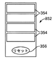
少なくとも1つの実施形態では、時間ベースのインジケータは、リセットボタンを押さえ保持したときに暗くなる複数のLCDバーが設けられたインジケータを含み、バーは、順次、所定の時間がたつと明るくなる。 In at least one embodiment, the time-based indicator comprises an indicator provided with a plurality of LCD bars that darken when the reset button is pressed and held, the bars sequentially brightening over a predetermined time.
少なくとも1つの実施形態では、磨耗の量を表示するための手段は、色変化またはマーキングの少なくとも1つが現れてまたは消えて磨耗を表示するように構成された磨耗インジケータを備える。 In at least one embodiment, the means for displaying the amount of wear comprises a wear indicator configured to indicate wear with at least one color change or marking appearing or disappearing.
少なくとも1つの実施形態では、システムは、さらに、コンピュータプロセッサを備え、ここでは磨耗の量を表示するための手段は、皮膚接触部材および導管の少なくとも1つの使用の累積時間を追跡するように構成されたコンピュータプロセッサを備える。 In at least one embodiment, the system further comprises a computer processor, where the means for displaying the amount of wear is configured to track the cumulative time of use of at least one of the skin contact members and conduits. Equipped with a computer processor.
少なくとも1つの実施形態では、磨耗の量を表示するための手段は、プロセッサを備え、ここではプロセッサは:導管に対する駆動機構の位置を追跡し;導管の圧力変化を、導管が最初に使用されたときの駆動機構の位置に対して相関付け;圧力変化を、導管の継続的使用中の位置に対して相関付けすることを継続し;継続的な相関からの相関値と、導管が最初に使用されたときの相関からの相関値とを比較し;相関値の比較に基づいて導管の磨耗の量を表示するように構成される。 In at least one embodiment, the means for displaying the amount of wear comprises a processor, where the processor: tracks the position of the drive mechanism relative to the conduit; pressure changes in the conduit, the conduit was first used. Correlate to the position of the drive mechanism when; continue to correlate pressure changes to the position of the conduit during continuous use; the correlation value from the continuous correlation and the conduit used first Compare with the correlation value from the correlation when it is done; it is configured to display the amount of wear of the conduit based on the comparison of the correlation values.
少なくとも1つの実施形態では、プロセッサは、搾乳ポンプシステム内に含まれる。 In at least one embodiment, the processor is included within the milking pump system.
少なくとも1つの実施形態では、プロセッサは、搾乳ポンプシステムの外部にある外部コンピュータ内に存在する。 In at least one embodiment, the processor resides in an external computer that is external to the milking pump system.
少なくとも1つの実施形態では、時間ベースのインジケータは、皮膚接触部材および導管の少なくとも1つの使用時間を追跡するように構成されたプロセッサを備える。 In at least one embodiment, the time-based indicator comprises a processor configured to track at least one usage time of the skin contact member and conduit.
少なくとも1つの実施形態では、皮膚接触部材および導管の少なくとも1つには、受動センサが設けられ、プロセッサは、システムの使用中、受動センサを追跡するように構成される。 In at least one embodiment, at least one of the skin contact members and conduits is provided with a passive sensor and the processor is configured to track the passive sensor during use of the system.
本開示の別の態様によれば、母乳を搾り出すためのシステムを作動させる方法は:システムを提供することであって、システムは、胸と共にシールを形成するように構成された皮膚接触部材と、皮膚接触部材と流体連通し、これに連結された導管と、圧縮部材を含む駆動機構であって、圧縮部材は、圧縮部材の内方向および外方向の移動に応答して、導管を圧縮し、導管の圧縮解除を可能にするように構成される、駆動機構と、センサと、駆動機構の作動を制御し、センサから信号を受け取るように構成された制御装置と、導管と流体連通する母乳収集容器とを備える、提供すること;皮膚接触部材を胸に対してシールすること;駆動機構を作動させて母乳を胸から抽出し、母乳を母乳収集容器内に圧送すること;導管の寸法および圧縮部材の位置に基づいて、母乳収集容器内に圧送された母乳の量を算出することのうち1つまたは複数を含む。 According to another aspect of the disclosure, the method of activating the system for squeezing breast milk is to provide the system, the system with a skin contact member configured to form a seal with the breast. , A drive mechanism that includes fluid communication with the skin contact member, a conduit connected thereto, and a compression member, the compression member compressing the conduit in response to inward and outward movement of the compression member. , A drive mechanism and a sensor configured to allow decompression of the conduit, a control device configured to control the operation of the drive mechanism and receive a signal from the sensor, and breast milk that fluidly communicates with the conduit. Provide, with a collection vessel; seal the skin contact member against the udder; actuate a drive mechanism to extract milk from the udder and pump the milk into the milk collection vessel; conduit dimensions and Includes one or more of calculating the amount of milk pumped into the milk collection vessel based on the position of the compression member.
少なくとも1つの実施形態では、圧送され母乳の量を算出することは:導管の寸法および圧縮部材の位置に基づいて、圧送された総量を算出することと;導管の圧力変化と圧縮部材の位置とを比較することによって実行された導管の伸展性査定に基づいて、圧送された母乳の量を総量の百分率として算出することとを含む。 In at least one embodiment, calculating the amount of pumped milk is: calculating the total amount pumped based on the dimensions of the conduit and the position of the compression member; with the pressure change of the conduit and the position of the compression member. Includes calculating the amount of pumped milk as a percentage of the total volume based on the duct extensibility assessment performed by comparing.
少なくとも1つの実施形態では、システムは、さらに、導管および母乳収集容器を相互連結する一方向弁を含み、方法は、さらに:一方向弁を監視して母乳が母乳収集容器内に流れ始め、母乳収集容器内に流れることを停止するときを決定することを含み;ここでは、母乳収集容器内に圧送された母乳の量を算出することは、母乳が母乳収集容器内に流入している間の時間にわたる導管の寸法および圧縮部材の位置に基づくものである。 In at least one embodiment, the system further comprises a one-way valve that interconnects the conduit and the milk collection container, and the method further: monitoring the one-way valve, milk begins to flow into the milk collection container and the milk begins to flow. Including determining when to stop flowing into the milk collection vessel; here, calculating the amount of milk pumped into the milk collection container is while the milk is flowing into the milk collection container. It is based on the dimensions of the conduit and the position of the compression member over time.
本開示の別の態様によれば、乳首シールドが:胸の乳首を覆うように構成され、第1の厚さを有する中央領域;および中央領域を取り囲む取り付け部分であって、胸に取り付けられるように構成され、第2の厚さを有する、取り付け部分のうち1つまたは複数を含み;ここでは、第2の厚さは、第1の厚さより大きく、中央領域は、1つまたは複数の開口部を含んで母乳が通り抜けることを可能にする。 According to another aspect of the present disclosure, the nipple shield is: a central region that is configured to cover the nipple of the breast and has a first thickness; and a mounting portion that surrounds the central region and is attached to the breast. Consists of one or more of the mounting portions having a second thickness; where the second thickness is greater than the first thickness and the central region has one or more openings. Allows breast milk to pass through, including the part.
少なくとも1つの実施形態では、第1の厚さは、約0.2mmから約1mmの範囲内の厚さであり、第2の厚さは、約2mmから約5mmの範囲内の厚さである。 In at least one embodiment, the first thickness is in the range of about 0.2 mm to about 1 mm and the second thickness is in the range of about 2 mm to about 5 mm. ..
少なくとも1つの実施形態では、第1の厚さは、約0.25mmである。 In at least one embodiment, the first thickness is about 0.25 mm.
本開示のこれらおよび他の特徴は、以下でより完全に説明するシステムおよび方法の詳細を読み取ることにより、当業者に明らかになるであろう。 These and other features of the present disclosure will become apparent to those skilled in the art by reading the details of the systems and methods described more fully below.
本発明のシステムおよび方法が説明される前に、本開示は、説明する特定の実施形態に限定されず、したがって、当然ながら変動し得ることを理解されたい。また、本明細書において使用する用語は、特定の実施形態を説明する目的にすぎず、本開示の範囲は付属の特許請求の範囲によってのみ限定されるため、限定的であるようには意図されないことも理解されたい。 Before the systems and methods of the invention are described, it should be understood that the present disclosure is not limited to the particular embodiments described and therefore can vary, of course. Also, the terms used herein are for purposes of describing a particular embodiment only and are not intended to be limiting as the scope of the present disclosure is limited only by the appended claims. Please understand that.
値の範囲が提供される場合、文脈がそうではないと明確に定めない限り下限の単位の10分の1までの、その範囲の上限値と下限値の間の各々の介在する値もまた、詳細に開示される。記述する範囲内の任意の記述する値または介在する値と、その記述する範囲内の任意の他の記述するまたは介在する値との間のより小さい範囲は、本開示に包含される。これらのより小さい範囲の上限値および下限値は、独立的に、その範囲内に含まれても、除外されてもよく、いずれかの限界値または両方の限界値が、そのより小さい範囲内に含まれる場合、またはいずれの限界値もそのより小さい範囲内に含まれない場合の各々の範囲もまた、任意の具体的に除外される限界値が記述する範囲内にあることを条件として、その開示に包含される。記述する範囲は、限界値の一方または両方を含み、これらの含まれた限界値のいずれかまたは両方を除外する範囲もまた、本開示内に含まれる。 If a range of values is provided, each intervening value between the upper and lower bounds of the range, up to one tenth of the lower bound unit, is also provided, unless the context explicitly states otherwise. Disclosure in detail. The smaller range between any descriptive or intervening value within the descriptive range and any other descriptive or intervening value within that descriptive range is included in the present disclosure. The upper and lower limits of these smaller ranges may be independently included or excluded within the range, and either or both limits are within the smaller range. Each range, if included, or if none of the limits are within its smaller range, is also subject to any specifically excluded limit being within the stated range. Included in the disclosure. The scope described includes one or both of the limits, and a range excluding either or both of these included limits is also included within the present disclosure.
別途定義されない限り、本明細書において使用するすべての技術的および科学的用語は、本開示が属する技術分野の当業者によって一般的に理解されるのと同じ意味を有する。本明細書において説明するものに類似するまたは等価の任意の方法および材料が、本開示の実践または試験において使用することができるが、好ましい方法および材料は、次に、説明される。本明細書において記載するすべての公報は、その公報が関連して引用される方法および/または材料を開示し、説明するために、参照によって本明細書に組み込まれる。 Unless otherwise defined, all technical and scientific terms used herein have the same meaning as commonly understood by one of ordinary skill in the art to which this disclosure belongs. Any method and material similar to or equivalent to that described herein can be used in the practice or testing of the present disclosure, but preferred methods and materials are described below. All publications described herein are incorporated herein by reference to disclose and explain the methods and / or materials to which the publication is cited in connection with it.
本明細書および添付の特許請求の範囲において使用するように、「1つ(a)」、「1つ(an)」、および「その」は、文脈が別途明確定めない限り、複数の指示対象も含むことが留意されなければならない。したがって、たとえば、「一センサ」は、複数のそのようなセンサを含み、「そのポンプ」への参照は、1つまたは複数のポンプおよび当業者に知られているその等価物などへの参照などを含む。 As used in this specification and the appended claims, "one (a)", "one (an)", and "that" are referents, unless the context specifically dictates otherwise. It should be noted that also includes. Thus, for example, a "one sensor" includes a plurality of such sensors, and a reference to "the pump" is a reference to one or more pumps and their equivalents known to those of skill in the art, etc. including.
本明細書において論じる公報は、本願の出願日より前のその開示のためだけに提供される。提供される公報の日付は、実際の正確な公報日付とは異なる場合があり、独立的に確認することが必要になり得る。
定義
The gazettes discussed herein are provided solely for their disclosure prior to the filing date of the present application. The dates of the publications provided may differ from the actual exact publication dates and may need to be confirmed independently.
Definition
本明細書において説明する「デッドスペース」という用語は、システムのポンプによって直接的に作用されないシステム内の容積部を指す。デッドスペースは、総容積から有効ポンプ容積を引くことによって算出される。総容積は、システム100が胸2に取り付けられシールされるときの、皮膚接触部材10、および乳首受け入れ部分112から一方向弁50までのチュービング32内の容積であり、それにより、総容積は、乳首3/乳輪4によって占有されない乳首受け入れ部分112内の空間およびそこから一方向弁50までの残りの容積である。有効圧送容積は、圧縮部材がフルストロークの一方の限界から他方の限界まで移動されるときに圧縮部材(たとえば圧縮部材38によって)変位される容積である。乳首はまた、圧力が変化するにつれて移動し、総システム容積の変化は、これら2つ(および任意の小さいシステム伸展性)の組み合わせである。デッドスペースは、システムの非圧送容積である。
The term "dead space" as described herein refers to a volume in a system that is not directly acted upon by the pumps of the system. Dead space is calculated by subtracting the effective pump volume from the total volume. The total volume is the volume within the
本明細書において使用する「降下モード」は、真空プロファイルが、より高い周波数および真空レベルにおけるより浅い(より小さい)振幅の変化を特徴とするモードを指す。降下モードはまた、「非栄養吸引モード」または「非栄養モード」と称されてもよい。 As used herein, "descent mode" refers to a mode in which the vacuum profile is characterized by shallower (smaller) amplitude changes at higher frequencies and vacuum levels. The descent mode may also be referred to as a "non-nutrient aspiration mode" or a "non-nutritive mode".
本明細書において使用する「抽出モード」は、真空プロファイルが、降下モード(非栄養モード)と比べて、より低い周波数および真空におけるより深い振幅の変化を特徴とするモードを指す。抽出モードはまた、「栄養吸引モード」または「栄養モード」と称されてもよい。 As used herein, "extraction mode" refers to a mode in which the vacuum profile is characterized by lower frequency and deeper amplitude changes in vacuum as compared to descent mode (non-nutrient mode). The extraction mode may also be referred to as a "nutrition aspiration mode" or a "nutrition mode".
「パージする」は、母乳をポンプチューブの有効圧送領域から収集室またはバッグ内に移送する動作を指す。 “Purge” refers to the operation of transferring milk from the effective pumping area of a pump tube into a collection chamber or bag.
「ラッチ吸引力」または「ラッチ真空」は、ポンプが胸に取り付けられたときに確立される最小の真空レベルを指す。これは、真空の最低レベルに設定され、その圧力は、大気圧を下回り、システムを胸に取り付けるのに効果的になる。
詳細な説明
"Latch suction force" or "latch vacuum" refers to the minimum vacuum level established when the pump is attached to the chest. This is set to the lowest level of vacuum, the pressure below atmospheric pressure, which makes it effective to attach the system to the chest.
Detailed explanation
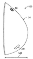
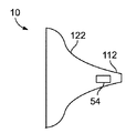
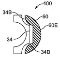
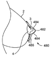
図1は、本開示の実施形態による(母乳収集容器無しの)搾乳ポンプシステム100の側面図である。システム100の外側シェル34は、ユーザの胸に合わせて輪郭付けされ、したがってユーザの衣服下にあるときにより自然な外観をもたらすように成形され構成される。図から理解することができるように、システムは、自然な胸のプロファイルを画定することができる。自然な胸プロファイルは、ユーザのブラに快適かつ好都合に嵌合し、自然に見せるように企図される。したがって、プロファイルは、全体的にドーム形状の構成で具現化されるものとは異なり、非円形のベースを有することを特徴とする。ベースから延びるのは、非対称パターンを有する湾曲した表面である。さらに、自然な胸と同じように、デバイスまたはシステムのプロファイルは、1つまたは複数の非対称曲線および中心を外した慣性中心を画定するように企図される。さまざまな自然な胸形状が、ユーザの好みおよび必要性から選択されるように提供され得る。図2は、図1のシステム100の遠位の斜視図であり、外側シェル34は、普通なら覆われる構成要素を示すために取り外されており/透明にされている。システム100は、(図2に示す胸フランジ、または異なる形状を有するが、着用者の胸に対してシールし、ポンプとの流体連通をもたらすように構成される部材など)皮膚接触部材10と、圧送領域30と、導管32とを含む。図3は、図2と同じ図であるが、皮膚接触部材10は、圧送領域30をより詳細に示すために取り外されている。
FIG. 1 is a side view of the milking pump system 100 (without a milk collection container) according to the embodiment of the present disclosure. The
図4は、本開示の実施形態によるシステム100の構成要素を示す。導管32は、小さい導管部分32Sの内側断面積より相対的に大きい内側断面積である大きい導管部分32Lを含む。両方の部分32Sおよび32Lは、断面が円形である管状部分として示されているが、一方または両方の部分を別の形で成形することもできるため、本開示はそのように限定されない。たとえば、図3の実施形態における導管領域32Lは、円筒状ではなく、ほぼ長円の面32Fと、これに対してほぼ垂直に延びる壁とを有するポンプ室として形成される。導管領域32Lのこの実施形態のさらなる詳細は、2014年9月19日出願の米国特許仮出願第62/052,476号明細書および2014年9月10日出願の米国特許仮出願第62/053,095号明細書において見い出すことができ、そのいずれも参照によって全体的に本明細書に組み込まれる。一方向弁50および大きい導管領域32Lを流体連通させて接合する導管領域32S2は、小さい導管領域32Sと同じ寸法のものになってもよいが、必ずしもそうではない。領域32Sおよび32Lと同じように、領域32S2は、断面が円筒状であり、円形のものでよいが、そうである必要はない。管状であるとき、その断面は、長円正方形、他の多角体形状、非対称形状、または非幾何学形状でよい。
FIG. 4 shows the components of the
図2〜3の実施形態では、ラッチング力、圧送力、および抽出力は、ドライバ44および46それぞれによって能動的に駆動される2つの圧縮部材36、38によって確立される。3つ以上の圧縮部材を使用し、また、1つまたは3つ以上のドライバを使用することができるが、現在好ましい実施形態は、図示するように2つのドライバによってそれぞれ駆動される2つの圧縮部材を使用する。図5は、圧縮部材36およびドライバ44をより詳細に示す図2〜3のシステム100の部分図である。図6は、圧縮部材38およびドライバ46をより詳細に示す図2〜3のシステム100の部分図である。
In the embodiments of FIGS. 2-3, the latching force, pumping force, and extraction force are established by two
図7A〜7Cは、本開示の実施形態による圧縮部材36、38の1つの例示的な作動モードを概略的に示す。図7Aでは、チュービング部分32Sおよび32Lは、圧縮部材36および38それぞれによって閉じられ、またはほぼ閉じられる。システム100の電源を入れたとき、圧縮部材36は、図7Bに示すように開き、圧縮部材38は、アンビル表面2232から引き離されはじめ、それによってチュービング32内の吸引力レベルを徐々に増大させる。(以下に説明する、圧力センサからとられた圧力読み取り値によって確認される)所定の最大吸引力レベルが達成されたとき、圧縮部材38は、現在の方向のその進行を止め、システム100の作動モードが、最大吸引力を維持するための所定の時間を有するとき、所定の時間の間その位置を維持する(またはわずかに同じ方向に移動して母乳がシステムに入るときの吸引力の低下を補償する)、または方向を反転させて、ラッチ吸引力レベルが達成されるまでチューブ32Lを圧縮する。圧縮部材が最初のストローク時にアンビル表面2232から離れるように完全に後退する時間までに、最大吸引力レベルが達成されなかった場合、圧縮部材36は、チューブ32Sを圧縮して現在の真空レベルを胸の環境内にシールし、圧縮部材38は、チューブ部分32Lを完全に圧縮してより多くの空気をシステムの外に(一方向弁50を通って外に)圧送する。次いで、圧縮部材36は、チューブ部分32Sを完全に開くように再度開き、圧縮部材は、別のストロークを実施して、アンビル表面2232から再度離れてより大きい吸引力レベルを生成する。このサイクル動作は、最大吸引力レベルが達成されるまで継続する。一部の場合、最初のストロークで最大吸引力レベルを達成することが可能であるが、その一方で別の場合では、複数のストロークが必要になり得ることが、留意される。
7A-7C schematically show one exemplary operating mode of
図7Bは、圧縮部材36が解放され、圧縮部材38が、アンビル表面2232から離れてチュービング32内の吸引力を増大させるときにチュービング部分32Sが完全に開くことを示している。最大吸引力を達成したとき、システムは、圧縮部材38が、最大およびラッチ吸引力レベルを達成する最大可能範囲までいずれの方向にも進行せず、それによっていくらかの反転吸引力および圧力生成能力を可能にするように設計されプログラムされ得る。最大吸引力レベルが達成されたとき、また、圧送プロファイルが、ラッチ圧力に戻るようにプログラムされたとき、圧縮部材38は、アンビル表面2232に向かって進んで、チュービング部分32Lを圧縮し、それによってチュービング32内の圧力を上昇させる。ラッチ吸引圧力の達成時、圧縮部材36はチュービング32Sを再度閉じて、ラッチ圧力が胸に対して維持され、それによって十分な吸引力が維持されることを確実にする。この段階では、圧縮部材38は、再度、アンビル表面2232から離れ始めて、吸引力レベルを最大吸引力まで増大させて戻し、圧縮部材36は開いて(アンビル表面2230から離れて)、チューブ32Sが開き、胸2が最大吸引力にさらされることを可能にする。あるいは、システムは、各サイクル内のある時点の間圧縮部材36が閉じず、ラッチ圧力を超えたときに圧縮部材が閉じる状態で、圧縮部材38が最大吸引力レベルとラッチ吸引力レベルの間でサイクル動作するようにプログラムされ得る。
FIG. 7B shows that the
母乳抽出モードの選択時、圧縮部材36および圧縮部材38は、ラッチモードと同じようにして、ただし選択された抽出モードによって決定された抽出波形をたどるようにして機能する。圧縮部材38の圧縮ストローク中、圧縮部材36は、ラッチ圧力/吸引力レベルが達成されたときに閉じる。圧縮部材38(図7C)による継続した圧縮は、圧縮部材36の下流側のチュービング32内の圧力を増大させて、正圧を確立してチューブ部分32Lの内容物(母乳)をチューブ部分32Lから、32Lの下流側のより小さいチュービング部分32S2を通り、一方向弁50を通って押し出す。達成された正圧は、母乳をチュービング32から母乳収集容器内に送るために一方向弁を開くのに十分なものである。1つの実施形態では、正圧は、20mmHgから40mmHgの範囲内であり、通常は約25mmHgである。圧縮部材38の動作を反転させたとき、圧縮部材36は開き、このとき吸引力レベルは、ラッチ吸引力レベルまで戻り、圧縮部材38は開き続けて、吸引力レベルを最大吸引力レベルまで増大させる。
When the milk extraction mode is selected, the
従来技術の搾乳ポンプシステムは通常、0mmHg(または0近く)とピーク真空、すなわち通常は250mmHg真空までの間でサイクル動作する。従来技術のシステムのフランジ(すなわち、胸に接触しこれに対してシールする構成要素)は、通常、成形された遠位部分と、大きい円筒形セクションとを有して、真空をかけることによって胸の乳首が前方に円筒形内に引き入れられるときにこれを収容する。これらの従来技術のポンプシステムによる圧送中、乳首は、0からピーク設定された真空までのサイクル動作にほぼ合致して前後にサイクル動作する。この動作は通常、少なくとも1cmの動作(乳首が少なくとも1cm伸張し、収縮する)であり、実質的にこれより大きくなり得る。研究では、授乳期の乳児から結果として生じる乳首動作は、それほど大きくなく、たとえば合計で約4〜5mmの動作であることが示されている(Elad paper、他のHartman group paper)。 Conventional milking pump systems typically cycle between 0 mmHg (or near 0) and peak vacuum, usually up to 250 mmHg vacuum. A flange of a prior art system (ie, a component that contacts and seals against the chest) typically has a molded distal portion and a large cylindrical section that is evacuated to the chest. Contain this when the nipple is pulled forward into the cylinder. During pumping by these prior art pumping systems, the nipple cycle back and forth in close agreement with the cycle operation from 0 to peaked vacuum. This movement is usually at least 1 cm (the nipple stretches and contracts by at least 1 cm) and can be substantially greater than this. Studies have shown that the resulting nipple movements from lactating babies are not very large, eg, movements totaling about 4-5 mm (Elad paper, other Heartman group paper).
本開示は、ラッチ真空を確立して皮膚接触部材/胸フランジ10が胸に対してシールするようにする。システムによって確立されたラッチ真空は、現行では約60mmHgであるが、約20mmHgから約80mmHgの範囲内の任意の値になることができる。システム100が皮膚接触部材10を介して胸にラッチされた後、システムは、次いで、ラッチ真空と目標(「ピーク」または「最大」とも称される)吸引力レベルとの間でサイクル動作する。システム100が、0mmHgまで下がらず、胸にかけられた吸引力を、ラッチ吸引力レベル(たとえば約60mmHg)である吸引力サイクルの最小端で維持するという事実により、乳首は、従来技術の搾乳ポンプシステムを使用することによるものほど収縮しない。乳首は、皮膚取り付け部材10内に、母乳を与えている間の乳頭部の形成と同じような形で初期のラッチ達成によって引き入れられることが、観察されている。真空がラッチ真空レベルと目標真空レベルの間でサイクル動作した後、真空が変化するにつれて乳首が前後する動作は、従来技術のシステムの使用によって起こるものと比較してかなり小さい。本システムの使用中の乳首動作(完全に伸張された寿小田井と完全に後退された状態との間の距離)は、通常、約2mm未満であり、一部の場合、約1mm未満である。
The present disclosure establishes a latch vacuum so that the skin contact member /
サイクル動作中の乳首のこの大きく低減された動作は、ラッチ真空レベルのラッチの確立、次いでラッチ真空(吸引力)とピーク真空(吸引力)の間の真空スイングの範囲を限定することに起因する。通常、ラッチ真空とピーク真空の間の真空差は、200mmHg未満であり、より一般的には150mmHgである。1つの例では、ラッチ真空は50mmHgであり、ピーク真空は200mmHgであり、その結果、150mmHgの真空差が得られた。 This greatly reduced movement of the nipple during cycle operation is due to the establishment of a latch at the latch vacuum level, which in turn limits the range of the vacuum swing between the latch vacuum (suction force) and the peak vacuum (suction force). .. Generally, the vacuum difference between the latch vacuum and the peak vacuum is less than 200 mmHg, more generally 150 mmHg. In one example, the latch vacuum was 50 mmHg and the peak vacuum was 200 mmHg, resulting in a vacuum difference of 150 mmHg.
本発明のシステムの使用で説明したように乳首動作を限定することにより、ユーザに対していくつかの利点が提供される。1つの利点は、乳首のフランジ壁に接する側の摩擦が小さく、それによって炎症、皮膚の損傷、疼痛、腫れなどのリスクを大きく低減することである。その結果、本発明のシステムは、授乳期の母親による使用をはるかに快適にし、この利点は、繰り返しの使用に対してますます顕著になる。少なくともラッチ吸引力レベルを常に維持することにより、本システムは、胸に対してより確実な持続的なシールをもたらし、空気および/または母乳の漏出の可能性を大きく低減する。乳首の移動がかなり小さくなるため、これは、ユーザに対して、授乳期の乳児の感触をより厳密にシミュレートするより「自然な」感覚をもたらす。乳首の進行は小さいため、これは、その長さを短くすることができるほどに、皮膚取り付け部材/フランジ10をより小さいプロファイル構成要素として設計することを可能にし、その理由は、従来技術のシステムが遭遇する乳首移動のより大きい長さを収容する必要がないからである。これは、システムの全体長さが、皮膚接触部材/フランジ10の長さの低減によって低減されるため、胸からのシステム100の突起部の全体量を従来技術のものより小さくすることを可能にする。こうして、乳首の先端部からシステムのハウジングの露出された端部までの距離は、低減される。
Limiting nipple movement as described in the use of the system of the present invention provides some benefits to the user. One advantage is that there is less friction on the side of the nipple that contacts the flange wall, which greatly reduces the risk of inflammation, skin damage, pain, swelling and the like. As a result, the system of the present invention makes use by lactating mothers much more comfortable, and this advantage becomes more and more pronounced for repeated use. By maintaining at least a latch suction level at all times, the system provides a more secure and lasting seal on the chest and greatly reduces the potential for air and / or milk leakage. This provides the user with a more "natural" sensation that more closely simulates the feel of the lactating baby, as the nipple movement is significantly smaller. Due to the small progression of the nipple, this makes it possible to design the skin attachment /
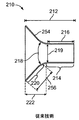
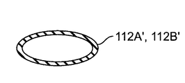
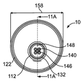
図8は、本開示の実施形態による皮膚接触部材10の側面図を示す。図示するように、胸接触部分122は、乳首受け入れ部分112の周りで対称的であるが、代替的には、乳首受け入れ部分112を、本明細書において説明するようにしてずらすこともできる。本実施形態における皮膚接触部材10の全体長さ110は、約63.75mmである。図9は、従来技術の胸フランジ210の長手方向断面図を示す。フランジ210の全体長さ212は、約60.6mmである。皮膚接触部材10は、従来技術のデバイスの乳首受け入れ部分214の内部容積と比べて、乳首受け入れ部分112の内部容積を低減するように設計され、これは、本開示による、皮膚接触部材10を含むシステム100を使用する母乳抽出プロセス中に、乳首3が遭遇する動作の量を大きく低減することによって可能にされる。皮膚接触部材10の乳首受け入れ部分112は、乳首の自然な形状により厳密に合致するように輪郭付けされ、それによって従来技術のシステム内の乳首周りに存在するデッドスペースを解消する、または大きく低減する。図示する例では、乳首受け入れ部分112は、胸接触部分122に隣接する部分112A内では円筒状であり、次いで、部分112Aからコネクタ134まで延びる部分112B内では円錐状にテーパになる。この設計は、乳輪4の一部分を乳首受け入れ部分112A内に受け入れながら、円錐部分112Bを提供することによってデッドスペースを限定することも可能にする。乳首受け入れ部分112のすべての断面の直径は、乳首の拡大を可能にするのに十分大きいものである。円錐状にテーパになる部分112Bの内径は、円筒状部分の内径に等しい内径からテーパになってより小さい内径に減少する。留意されるように、乳首受け入れ部分112の長さは、従来技術のものよりかなり小さい。図8に示す例では、乳首受け入れ部分112の長さ114は、従来技術の乳首受け入れ部分214の36.9mmの長さ216(約350mmから約500mmの範囲内になり得る)と比較して、約23mmである。長さ112は、約22mmから約29mmの範囲内で変化し得る。乳首受け入れ部分112の長さ114は、乳首3の遠位先端部を乳首受け入れ部分112の近位端部と接触させることなく、真空下で乳首3の拡張を可能にするのに十分なものである。
FIG. 8 shows a side view of the
本システム100を用いた実験は、女性の乳首の大部分が、約50mmHg(−50mmHg圧力)のラッチ吸引力の下で約1.6cmの長さで乳首受け入れ部分112内に延びることを示した。(ラッチ真空下で乳首の長さを超える)乳首受け入れ部分112によってもたらされる余分の長さは、目標真空下で乳首の少量の伸張、通常は約150mmHgの最大吸引力の下で約1〜2mmの伸張を可能にし、ポンプを準備するときに乳首が遭遇し得る、少量のさらなる前方動作を可能にするために提供される。したがって、乳首受け入れ部分内には、ラッチ圧力下にあるときに乳首3の先端部の近位に長手方向に延びる、少なくとも約2mm、最大でも約6mmの空間が設けられる。
Experiments with the
乳首受け入れ部分112の乳首入り口の直径116は、乳首が真空下でのいくらかの拡張から抑制されないように、乳首サイズのほとんどを収容するのに十分な大きさである。乳首3は、先端部よりも基部(乳輪4と接合する領域)において大きく直径が拡張し、それによって乳首受け入れ部分112Bを図示するように円錐形状にすることを可能にする。乳首受け入れ部分112の入口開口部の直径116は、図8の実施形態では、約24mmであるが、約22mmから約29mmの範囲内になり得る。乳首受け入れ部分112Bの近位端部における内径118は、図8では約13.16mmであるが、約9mmから約20mmの範囲内になることができる。対照的に、フランジ210の部分214の内径218は、部分214の全体長さにわたって約23.5mmである。
The diameter 116 of the nipple inlet of the
乳輪4の一部分もまた、乳首受け入れ部分112内に引き入れられることがあり、それにより、これは、圧送システム100によって交互に、圧縮され、そして少なくとも部分的に圧縮から緩和されて、乳児が自然に飲む方法をシミュレートする。しかし、皮膚接触部材10は、乳輪4が完全に乳首受け入れ部分112に入るのを制限し、乳首3および乳輪4以外の胸2の部分が、乳首受け入れ部分112に入るのを制限するように構成される。これにより、乳首3の先端部が、最大真空下であっても乳首受け入れ部分112の近位端部に接触することが防止される。
A portion of the
本明細書において開示する皮膚接触部材10の実施形態のいずれにおいても、乳首受け入れ部分112の上部は、比較的硬度のあるおよび/または堅さの材料から形成され、乳首受け入れ部分112の底部は、比較的軟質のおよび/またはより可撓性の材料から形成されて、使用中の授乳期の乳児をより良好にシミュレートすることができ、その理由は、乳首3の底部に接触する乳児の舌は、授乳中、乳首3の上部に接触する乳児の口蓋より軟質であり、可撓性であるためである。
In any of the embodiments of the
胸2の制限を容易にするために、胸接触部分122には、1つまたは複数の粘着性の部分360が設けられ、これは図29A〜29Bを参照されたい。粘着性領域360は、図29A〜29Bでは、胸接触部分122の内部表面周りの連続的なリングとして図示されているが、この円周の1つまたは複数の部分を渡してもよく、1つまたは複数のセグメントとして設けることができる。粘着性領域(複数可)は、皮膚接触部材10の残りの部分より胸2との摩擦を大きくし、それによってこの部分に接触する胸2の部分に対する抵抗をもたらして、胸が乳首受け入れ部分112に向かって引き入れられることを防止する。粘着性領域160は、皮膚接触部材10の残りの部分とは異なる材料によって形成されてよく、および/または摩擦の増大をもたらすコーテイングまたは粗面化領域でもよい。たとえば、粘着性部分は、シリコーンでよく、このとき皮膚接触部材の残りの部分は、ポリエチレン、または本明細書において説明する、皮膚接触部材を作製するのに使用するための他の材料のうちの1つから形成される。胸のこれらの部分が乳首受け入れ部分112内に摺動すること防止することにより、これは、あまりに多くの胸の組織を圧縮することによる疼痛の発生を低減し、乳首3が母乳量の圧搾のために自然に拡張するのに十分な空間を乳首受け入れ部分112内にもたらす。
To facilitate the limitation of the
皮膚接触部材10の胸接触部分122の内部角度120は、本発明のシステム100で使用するのに合わせて、また、ユーザの快適感を最大限にするように設計される。この内部角度はまた、胸2の部分が前方に乳首受け入れ部分112内に入りすぎるのを制限する能力を促進することもできる。図8の実施形態では、内部角度120は、約112°であり、これは、従来技術のフランジの内部角度より広い。たとえば、従来技術のフランジ210の胸接触部分220の内部角度218は、90度である。より広い角度120は、胸の組織が、乳首受け入れ部分112内に送り込まれることを防止するのを助け、それにより、乳首受け入れ部分112内に受け入れられる胸の組織はより少なくなり、それによってこの皮膚接触部材10の使用を従来技術のフランジより快適にし、乳首拡張のための空間をもたらす。より広い角度120を提供することにより、これはまた、システム全体を効果的に短くすることを可能にし、システムが胸に対してより平坦に位置することを可能にして快適性および外観の両方を改善する。図8の実施形態では、胸接触部分122の長さ124は、15mmであるが、約12mmから約19mmの範囲内になり得る。対照的に、胸接触部分220の長さ222は、25.8mmであり、それによってフランジ210を使用するシステムを、皮膚接触部材10を使用するシステムよりも、胸からさらに遠くに延在させる。
The internal angle 120 of the
図30A〜30Bは、相対的に大きい内部角度122Aを有する皮膚接触部材122Aと、相対的に小さい内部角度122Bを有する皮膚接触部材122Bとの間の相違を示す。より小さい角度122Bは、胸のサイズおよび形状においてより多くのバリエーションで比較的より多くの胸組織と相互作用する能力をもたらす。図30Aに示す皮膚接触部材の122Aの胸接触部分は、図30Bに示す胸接触部材122Bの内部角度120Bより大きい内部角度120Aを有する。その結果、これらの皮膚接触部材10が胸2に装着されたとき、362Aにおける胸組織と胸接触部材122Aの最初の接触は、胸組織が362Bにおいて胸接触部材122Bと最初に接触する場所より、胸接触部分122A上ではより低いところにある(またはより中にある)。胸接触部分122B上の胸2のより高い(より外にある)最初の接触場所362Bは、胸接触部分122上の胸2のより多くの接触表面をもたらし(364Bの長さを364Aと比較する)それによって、乳首受け入れ部分112内の組織の移動をより良好に制御し、利用可能な表面接触領域が増大することにより、乳頭部上に、これが形成されるにつれてより多くの張力を作り出す。乳頭部は、より早急に形成され始め、胸上の増大された張力は、胸組織2および乳輪4の遠位部分が乳首受け入れ部分112内に吸引されないようにするのを支援する。乳頭部を形成する乳輪4および乳首3のより大きい長さ366Bおよび領域は、図30Aの実施形態の長さ366Aおよび領域に比べてより小さい角度120Bによってもたらされ、その理由は、366Bは、長さ366Bにわたる皮膚接触部材の内部容積を長さ366Aにわたる皮膚接触部材の内部容積より大きくするのに十分な量だけ、長さ366Aより大きいためである。図30Aの実施形態のより大きい角度122Aにより、乳輪は、胸2と部分122Aの最初の接触時に胸接触部分122Aの側部と接触し、それにより、乳輪4が拡張する余地は存在しない。最適な結果にするために、母乳抽出中、乳輪4を長くし、広くすることが必要であり、その理由は、これは、乳児が母乳を飲むときに起こるものであるためである。胸2と胸接触部分122との最初の接触時に乳輪4と乳首受け入れ部分112の開口部との間に設けられる空間は、乳首3が乳首受け入れ部分112内に引き入れられるときに乳輪4が長くなり膨張する(広くなる)ことを可能にする。図30Cは、膨張できない場合母乳を効率的にまたは全く排出しない乳管を含むという理由から、母乳の最適な抽出のために膨張する十分な余地を必要とする、乳首3との接合部にある乳輪4の部分4Pを示している。本開示の皮膚接触部材10は、好ましくは、乳輪4の最大約0.25インチ(約0.5cm)が乳首受け入れ部分112内に引き入れられ、乳輪のさらなる部分が乳首受け入れ部分112に入ることを防止するように構成される。
30A-30B show the difference between the
図8Bの実施形態における、胸接触部分122および乳首受け入れ部分112を形成する材料の厚さは、約1.5mmであるが、この厚さは、約1mmから約4mmの範囲内になり得る。あるいは、胸接触部分122および乳首受け入れ部分112の厚さは、互いに異なっていてよい。胸接触部分122および乳首受け入れ部分112ならびにチュービングコネクタ134は、シリコーンまたは他の伸展性の生体適合性材料、たとえばそれだけ限定されないが、ポリウレタンおよび/ポリエーテルブロックアミド(PEBAX)などから作製されて胸との軟質の界接をもたらし、胸の乳輪および乳首周りにシールをもたらすこともできる。胸接触部分122の内側ハウジング126は、剛性、半剛性、または伸展性になることができる。同様に、乳首受け入れ部分112も、剛性、半剛性、または伸展性になることができる。乳首受け入れ部分112に隣接しその入り口としての役割を果たす胸接触部分122の部分は、乳輪4の少なくとも周囲部分と接触するように構成され、(乳首受け入れ部分112の滑性と比べて)滑性が小さい材料から作製されて、乳輪の少なくとも周囲上でより大きい摩擦抵抗をもたらして、乳輪が乳首受け入れ部分112内に引き入れられることを防止するのを助け、胸組織上に乳首3および乳輪4から離れる張力をもたらして、乳首受け入れ部分112内に入ることが可能になる乳輪4の量を制御することができる。本発明のシステム100は、圧送中、乳首3の移動を大きく低減するため、より多くの摩擦および張力をもたらす表面は、圧送中にかなり多くの乳首3の移動に遭遇するときに現在利用可能な乳首フランジにおいて遭遇する組織の擦傷または水疱形成のリスクを低減する。乳首受け入れ部分112および内側ハウジング126は、異なる材料および/または硬度および/または剛性の材料から作製することができる。たとえば、内側ハウジング126は、剛性になることができ、乳首受け入れ部分112は、伸展性になることができ、または材料、硬度、および剛性の任意の他の組み合わせを提供することができる。好ましくは、胸接触部分122および乳首受け入れ部分112は、伸展性であり、シリコーンから作製されるが、それだけに限定されないが、ポリエチレンテレフタレート(PET)、ポリウレタン、ポリエチレン、高密度ポリエチレン(HDPE)、低密度ポリエチレン(LDPE)、ポリアミド、ポリエチレンテレフタレート(PET)および/またはPEBAXを含む、他の材料および材料の組み合わせを使用することができる。伸展性が存在する実施形態では、乳首受け入れ部分112は、システム100を使用して母乳を胸から抽出する間、反復的に開閉することができ、それによって乳児が母乳を吸っているときの乳首に対する舌の順序に類似する送りサイクルをシミュレートすることができる。
In the embodiment of FIG. 8B, the thickness of the material forming the
図8の実施形態では、乳首受け入れ部分112は、円筒状である部分112Aと、約60度である円錐形状部分112Bの内部角度130を有する、円錐形状にされた部分112Bとを含む。円錐の内部角度は、約55度から約65度の範囲内になり得る。
In the embodiment of FIG. 8, the
円筒状部分112Aおよび円錐形状部分112Bの両方は、図8の線10A−10Aに沿って切り取られた図10Aの断面図によって例示するように、断面が円形である。あるいは、部分112A、112Bの一方または両方は、図10Bの112A’、112B’によって示すように、断面が卵形または楕円形でよい。この卵形または楕円形の断面は、母乳を飲む乳児の口の形状により厳密に似ており、したがって、赤ちゃんが母乳を飲むことにより類似する圧力/力輪郭を乳首にもたらすことになる。
Both the
さらに代替的には、皮膚接触部材10は、乳首受け入れ部分112への調整可能な開口部132を有することができ、また、フランジ角度120も調整可能でよく、それにより、胸接触部分122および開口部の両方を、乳輪に対する嵌合および乳首の受け入れを最適化するようにサイズ設定することができる。少なくとも1つの実施形態では、胸接触部分122の内側に、インサートが設けられる。追加的にまたは代替的には、インサートは、胸接触部分122の後部に設けることができる。これらの配置のいずれにおいても、インサートは、胸2に対する胸接触部分122の角度を、これが胸上に装着されるときに変更する。さらに、インサートは、開口部をより小さくするために設けることができる。フランジ角度120および開口部132の直径の種々の組み合わせが、胸の種々のサイズおよび形状に対して必要とされ得る。たとえば、比較的小さい開口部132および比較的小さい角度120は、平均より比較的弾力がある胸に対して必要とされ得、一方で比較的大きい角度120および比較的大きい開口部132は、平均より張りがある胸に対してより良好になり得る。さらに代替的には、皮膚接触部材10の組が、角度120および開口部132のバリエーションに範囲を与えるために提供され得る。壁厚128もまた、胸接触部分122の角度120の変化に対応するために変更され得る。
Further alternative, the
部分134は、皮膚接触部材10をチュービング32と流体連通させて連結するために使用されるチュービングコネクタである。チューブ32との流体連通をもたらす開口部138の直径136は、図8では約25mmであるが、約20mmから約28mの範囲内になり得る。部分134の長さ142は、図8では約23.8mmであるが、約20mmから約28mmの範囲内になり得る。
The
図11Aは、図11Bの線11A−11Aに沿って切り取られた皮膚接触部材10の長手方向断面図であり、図11Bは、本開示の別の実施形態による皮膚接触部材10の遠位端面図である。この実施形態では、乳首受け入れ部分112は、胸接触部分122が乳首受け入れ部分112と同心である図8の実施形態とは対照的に、胸接触部分122に対して中心に置かれない。その代わり、この実施形態では、乳首受け入れ部分112の中央軸146は、皮膚接触部材が、胸への取り付けのためにこれが使用される配向に置かれたとき、胸接触部分122の中央軸148の下方に位置決めされ、これは図11Bを参照されたい。この実施形態では、乳首受け入れ部分112への開口部132は、図8の実施形態のものよりわずかに直径が大きく(25mm対23mm)、それによってわずかに大きい乳首を有するユーザに対応する。図9に示す従来技術のフランジ210の開口直径219は、約21mmから約32mmの範囲内になり得る。当然ながら、本開示のずらした実施形態は、より小さい開口部132のサイズを使用することもできる。同じように、図8の実施形態に、より大きい開口部132のサイズを設けることもできる。このずらした実施形態では、胸接触部分122の中央軸150(ならびに中央軸150および164が図11Aの実施形態のように平行であるときは乳首受け入れ部分112の中央軸164)に対する、乳首受け入れ部分112の上方にある胸接触部分122の角度120Aは、中央軸150および164に対して、乳首受け入れ部分112の下方にある胸接触部分122の角度120Bより平坦であり、これは図11Aを参照されたい。他の実施形態では、中央軸150は、中央軸164と平行ではない。図11Aに示す例では、角度120Aは、約69度であり、角度120Bは、約52度である。しかし、角度120Aは、約32度から約85度の範囲内の任意の角度でよく、角度120Bは、約32度から約85度の範囲内の任意の角度でよい。この構成は、両方の角度120Aおよび120Bが等しい場合の設計と比べて、胸接触部分122が接触する胸の自然な湾曲に対するより良好な嵌合をもたらす。胸接触部分122の遠位開口部152周りの周囲の平面を、図11Aに示すように中央軸150に対してほぼ垂直に維持するために、開口部132の上部から遠位開口部152の周囲の上部までの距離154は、角度120Aおよび角度120Bの相違により、開口部132の底部から遠位開口部152の周囲の底部までの距離156より大きいものである。図11Aに示す例では、距離154は、約36.32mmであるが、約15mmから約62mmの範囲内の任意の値でよく、距離156は、約21.3mmであるが、約10mmから約58mmの範囲内の任意の値でよい。遠位開口部(図11Bを参照)における胸接触部分122の外径158は、約82.3mmであるが、約60mmから約150mmの範囲内の任意の値でよい。遠位開口部152周囲の上部から乳首受け入れ部分の中央軸164までの距離160は、図11Aの実施形態では約49.8mmであるが、約30mmから約60mmまでの範囲内の任意の値でよい。図11Aの実施形態における遠位開口部152の周囲の底部から乳首受け入れ部分の中央軸164までの距離162は、約33mmであるが、約25mmから約40mmの範囲内の任意の値でよい。これに対して、図9のフランジ210は、対称的であり、このとき遠位開口部の周囲の上部からフランジ210の中央軸までの距離254は、28.2mmであり、遠位開口部の周囲の底部からフランジ210の中央軸までの距離256は、28.2mmである。
11A is a longitudinal sectional view of the
複数の穴またはポート140が、乳首受け入れ部分112とチュービングコネクタ134との界接面において設けられて、乳首3から引き出された母乳が、チュービングコネクタ134に連結され穴/ポート140と流体連通する、チュービング32に入ることを可能にする。これらの穴/ポート140は、母乳をチュービングコネクタ134およびチュービング32内に送ることを可能にし、また、乳首3がチュービングコネクタ134およびチュービング32内に引き入れられることも防止する。
A plurality of holes or
図12Aは、外側シェル34を伴った、皮膚接触部材10およびチューブ32の側部断面図である。図12Bは、システム100の底部からの横断方向断面図であり、皮膚接触部材10およびチューブ32を外側シェル34と共に示す。チューブ32は、簡単にするために単一のサイズ設定されたチューブとして概略的に示されているが、この実施形態における大きい部分32Lは、これより小さいチューブ部分32Sの内径より大きい内径を有する。図12Cは、皮膚接触部材10の近位端面図であり、これに連結されたチューブ32を示す。1つの実施形態では、チューブ32Lの内径は、約3/8”(9.53mm)である。別の実施形態では、チューブ32Lの内径は、約7/16”(1.11cm)である。別の実施形態では、チューブ32Lの内径は、約1/2”(1.27cm)である。別の実施形態では、チューブ部分32Lの内径は、約5/16”(7.94mm)である。1つの実施形態では、チューブ部分32Sおよび32S2の内径は、約1/4”(6.35mm)である。別の実施形態では、チューブ部分32Sおよび32S2の内径は、約3/32”(2.38mm)である。別の実施形態では、チューブ部分32Sおよび32S2の内径は、約1/8”(3.18mm)である。
FIG. 12A is a side sectional view of the
1つの実施形態では、総システム容積は約24.0ccである。総容積は、乳首受け入れ部分112内の(乳首3によって占有されない)空間および一方向弁50までのチューブ部分32S、32L、および32S2の部分として算出され、これは図13の概略図を参照されたい。他の実施形態は、好ましくは約4.5ccから約12ccまでの範囲の、より好ましくは約5ccから約8ccまでの範囲の、または約8ccから約10ccまでの範囲のかなり小さい総システム容積を有することができる。約24.00ccの総システム容積を有する実施形態では、有効ポンプ容積、すなわちチューブ部分32Lを完全に圧縮されない状態から圧縮の限界まで圧縮部材38によって圧縮することによって達成可能な容積変位は、約3.4ccである。この実施形態における圧縮部材38は、約2.5”(6.35cm)の(図14に示すように規定された長さ38Lを有する)圧縮部材長さ38Lを有する。システム100のチュービング32内に空気のみが存在するとき、圧縮部材38を、チュービング部分32Lに対して内方向に、また、チュービング部分から離れるよう外方向に移動させることによる圧力スイングは、空気の圧縮性によって限定される。この実施形態では、システムが−60mmHgの真空下にあるとき、圧縮部材のフルストローク(圧縮された状態から全く圧縮されない状態のチューブ部分32L)は、真空を−160mmHgまで増大させる。総システム容積に対する圧送容積の比は、圧送システムの電力およびサイズに関して重要である。この実施形態では、チューブ部分32Lは、0.375”(9.53mm)の内径および0.094”(2.39mm)の壁厚を有し、50ショアAの硬度を有して、シリコーン(Dow Corning社、SILASTIC(登録商標))から作製された。2.5”(6.35cm)の長い圧縮部材を使用することにより、完全圧縮下のチューブ部分32Lにかけられた力は、19.6lbfであった。
In one embodiment, the total system volume is about 24.0 cc. The total volume is calculated as the space within the nipple receiving portion 112 (not occupied by the nipple 3) and the portion of the
好ましい実施形態では、チューブ部分32Lを完全に圧縮すること、およびチュービング部分32Lの完全な反発を可能にすることも回避することが好ましい。ほぼ完全な圧縮では、圧縮力における急な増大が必要とされ(図15、#302を参照)、これは、モータ出力およびこれが必要とするエネルギー消費のかなりの増大を考えると、それによって得られる少量のさらなる圧力変化には効率的ではない。チュービング部分のほぼ完全な反発では、その結果となる圧力変更は、圧縮部材38を完全に引き出すためにドライバ46によって消費されるエネルギーの量を考えると、あまり効率的ではなく、これは図15#305を参照されたい。システム100の降下モード作動中、システム100は、胸2内の母乳の降下を、抽出の前に、降下を確立するための120mmHgまでの最大吸引力目標(通常は、約100mmHg(−100mmHg圧力))を用いて、もたらすように作動する。降下モード(または非栄養吸引モード)の目的は、胸2を刺激して母乳を圧搾することである。この段階中の圧送の比較的浅く(小さい真空変化の範囲)、比較的高速の周波数は、胸で子供が最初に母乳を飲む動作をまねることを意味する。このモードでは、チュービング圧縮(図15#305)の最初の10%は、あまり生産的ではない。その理由は、降下段階中、吸引圧力は、110mmHgまたは120mmHgの最大降下吸引力を超えることは可能にされず、またはどのような最大降下吸引力が設定されても、圧縮部材38は、チュービング圧縮の最初の10%の範囲までサイクル動作を行わないためである。したがって、圧縮部材38がチューブ部分32Lから離れる方向に引き出されるにつれて、システム100は、圧縮部材38が、チューブ32Lが90%である圧縮されない位置に到達するまでに、100mmHg(100mmHgの吸引圧力)(または−120mmHg、または最大降下吸引力が設計されるあらゆる値)に到達するように設計され、これは307を参照されたい。90%から100%圧縮された状態までの圧縮部材38のチューブ部分32Lから離れるさらなる移動(領域305を参照)は、チューブ部分32Lが、膨張のこの部分中、脆弱ばねのように機能するため、追加の真空を生成するにはあまり役に立たない。図15内のグラフは、特有のレベルまでの圧縮後のチューブ部分32Lによる反発圧力の生成を追跡する。たとえば、チューブ部分32Lを100%圧縮し、その後チューブをシールし、これを反発させることによって、>300mmHgが生成される。10mmHgを生成する小さい偏向は、システム100の圧送目的には「有用」ではない。200mmHg真空は、チュービング32Lが約25%圧縮され、次いで解放されたときに確立され、これは309を参照されたい。圧縮部材38は、システム100の圧送目的に有用である真空生成の範囲内で作動することだけを必要とする。圧縮部材38を作動させてチューブ部分32Lをほぼ100%に圧縮することは、圧縮負荷の上昇(ramping up)により非効率である。また、圧縮部材38のパドルをチュービング部分32Lのほぼ0%圧縮で作動させることは、低真空ピークを制御するためだけに有用である。チュービング部分32Lが反発するとき、これは、真空引き出しのための容量に到達し、圧縮部材38のチュービング部分32Lからのさらなる引き離しは、パドルにチュービング部分32Lとの接触を失わせるだけである。
In a preferred embodiment, it is also preferred to avoid completely compressing the
降下(非栄養)モード中、システム100は、1つの例では−60mmHgから−100mmHgの間で作動するように構成され得る。この例では、圧縮部材38は、チュービ部分32Lをほぼ完全に(たとえば約97%)圧縮し、次いで、チュービング部分32Lから離されて真空を生成することができる。−100mmHgの最大ラッチ吸引圧力は、チュービング部分32Lの少量の反発によって到達され、圧縮部材38は、チュービング部分32Lの完全な圧縮に近い狭い範囲または帯域内で−100mmHgから−60mmHgの間でチュービング部分32Lに対してサイクル動作することができる。母乳が流れるにつれて、100までのその狭い帯域のシフト(その場の容積→パドル上昇の容積)が、約10%(90%反発)で生成され、この時点では、チューブ部分32Lは、これを完全に(100%またはほぼ100%の圧縮される状態に)圧縮することによってパージされて、内容物を押し出し、それによってチューブ部分32Lの比較的小さい圧縮力によって再度圧送するためのより多くの容量を取り戻す。別の実施形態では、圧縮部材38は、チューブ32Lを約10%>圧縮された状態から約97%圧縮された状態まで圧縮する範囲で作動する。追加的に、圧縮部材38は、チューブ32Lが、チュービング32の設置、変更などを可能にするために0%圧縮される位置まで移動することができる。通常、パージ中、真空レベルは、最小真空(たとえば、約−60mmHg)まで低減され、圧縮部材36は、チュービング部分32を閉じ(シールし)て胸2に対して60mmHg真空を維持するために使用される。次いで、圧縮部材38は、チュービング部分32Lを完全に圧縮してチュービング部分32Lの内容物をパージする。
During descent (non-nutrition) mode, the
圧縮部材38の接触表面は、圧送の効率性を改善し、システム100の動力要求事項を低減するように成形され得る。図16は、チュービング部分32Lの圧縮中の圧縮部材38の端面図を示す。圧縮部材38の接触表面38Sは、たとえば、角をとることなどによって圧縮部材38の長手方向軸に横断する方向に凸状であり、それによってチューブ部分32Lの側壁の非生産的な圧搾を回避する。これは、ドライバ46上のピーク負荷を最小限にする。図16では、チューブ32Lの中央部分が、内壁が互いに接触するために完全に閉じられており、一方で環状部の側部近くの部分は、完全に閉じていないことを見ることができる。
The contact surface of the
24.0ccの総システム容積を有する実施形態では、19.6lbsの圧送力が、ドライバ46および圧縮部材38によってもたらされた。推定される機構容量は、44lbであった。「機構容量」は、ドライバ46および圧縮部材38によってチュービング部分32Lにかけることができる最大圧縮力を指し、電圧、ドライバ46ストールトルク、およびギヤ低減などのドライブトレインの他の特性などの因子である。システムは、サーボモータをドライバ46として使用し、このドライバは、圧縮部材38に0.188”(4.78mm)レバーアーム304(図14を参照)によって連結されて、246:1のギヤ比および5.9ft−lbトルクを500mA電流の流れによってもたらした。このポンプシステムの所望の最大速度は、90サイクル/分(CPM)であり、このとき最大圧縮進行は約65CPMに限定される。圧縮進行(ストローク)が低減されたとき、たとえば降下モードにあるとき、速度は増大され得る。ポンプシステムは、「乾燥」の100mmHgスイングを有し(すなわち真空変化は、チュービング32内に流体がないとき、フルストロークの一方の端部から他方まで約100mmHgである)、そのためフル進行ストロークは、降下モードでは必要とされないことがあり、これは、真空スイングが、100mmHg未満、たとえば約60mmHgラッチ吸引力から約100mmHg最大吸引力までになるためである。圧送システムの力要求事項は、総システム容積内のデッドスペースを低減することによって大きく低減することができ、それによってさらにサイクル/ストロークあたりの圧送容積は少なくてすむ。ギヤ比を低減することにより、これは、圧縮部材の作動を増大させてこれを圧力変化によりすばやく、より敏感にすることができる。
In an embodiment having a total system volume of 24.0 cc, a pumping force of 19.6 lbs was provided by the
ドライバ44および圧縮部材36は、約1.0lbfを3/8”(9.53mm)内径を有するチューブにかけて、これを完全に閉じる(ピンチする)ように構成された。ドライバ44は、0.51”(1.3cm)×1.14”(2.9cm)×1.2”(3.05cm)の寸法、3.0in−lb.ストールトルクおよび0.238”(6.05mm)レバーアームを有するHS―85MGサーボモータを含んで、約12.8lbf容量をもたらした。
The
図17は、上記で説明した、24.0ccの総システム容積、0.375”(9.53mm)内径チューブ32、および2.5”(6.35cm)圧縮部材38を有する上記で説明したシステムの電力消費データを示す。ドライバ44、46は、約6Vの電圧330を供給する4つのアルカリCサイズの電池によって電力供給された。電流は、ドライバに接続された電池と直列のマルチメータを使用して測定された。システムは、作動中、圧縮部材38をフルストロークでチューブ部分32Lに対して駆動するように設定された。単一の15分の圧送セッションは、約110mAhの電力を必要とし、これは336を参照されたい。圧送の1日分の推定量は、4セッションとして設定され、その結果一日の電力要求338は、約440mAhとなった。平均電流332は、約440mAになると算出され、最大電流338容量は、約0.83Aであった。
FIG. 17 shows the system described above having a total system volume of 24.0 cc, a 0.375 ”(9.53 mm)
1つの実施形態では、搾乳ポンプシステムの他の構成要素(外部シェル34の上方に装着可能である母乳収集容器を除く)を含む外部シェル34は、約11cm(4.3”)の直径340(図18を参照)および約4.1cm(1.6”)の長さ342(図1を参照)を有するように構成されるが、直径340は、約10cmから約14cmの範囲内の任意の値でよく、長さ342は、約3.5cmから約6cmの範囲内の値でよい。約11cmの直径340および約4.1cmの長さ342を有する外部シェル34は、約151.2ccの構成要素のハウジング容積をもたらす。乳首受け入れ部分112内の死容積が約1.8ccであり、チュービング32の1cm長さが圧縮部材36による圧縮のために提供され、乳首受け入れ部分112が約1.5cmだけ胸接触部分122の中心からずれていると想定して、図19は、さまざまなチュービング寸法を有するシステム100の特性を示す。これらの特性は、全体にわたって均一であり、したがって、より小さいチュービング部分32Sおよびより大きいチュービング部分32Lを有さないチュービング32を使用して測定されたが、その原理は、依然として小さい32Sおよび大きい32Lの部分両方を有するチュービング32を使用する場合と同じである。死容積350および352を低減することにより、圧送の効率354(総システム容積352および356によって割られた圧送容積)は、増大することが分かり得る。これは、圧縮部材38の長さ38Lの低減を可能にし、その結果、ポンプ出力およびエネルギー消費要求事項は比較的小さくなる。
In one embodiment, the
システム100は、母乳がチュービング32に入ることによって引き起こされたチュービング32内の圧力変化に反応する。図20は、本開示の実施形態によるシステム100の作用構成要素の概略図である。圧縮要素36および38は、専用の圧縮ドライバ44、46によって駆動される。代替的には、圧縮要素36および38は、単一の圧縮ドライバによって駆動することができ、このドライバは、制御装置52によって制御されて圧縮要素36、38の各々を望ましい方法で駆動する。図示するように、圧縮要素36、38は、ピストンを備えるが、代替的特徴、たとえばレバーアーム、ねじドライブ、クランプ、カム、ペンチ、ローラ、磁石、電磁石、リニアドライブ、ソレノイド、ギヤ、ステッパモータ、または他の特徴それぞれを使用して同じ機能を達成することができる。圧縮部材およびその圧縮表面の代替的な実施形態のさらなる特徴は、2014年7月22日出願の米国特許仮出願第62/027,685号明細書、2014年9月16日出願の米国特許仮出願第62/050,810号明細書、2014年9月19日出願の米国特許仮出願第62/052,476号明細書、2014年9月19日出願の米国特許仮出願第62/053,095号明細書に見いだすことができ、これら文献の各々は、参照によって全体的に本明細書に組み込まれる。
各々の圧縮要素36、38は、圧縮要素36、38の独立的であるが、連携した駆動および後退のために、ドライバ44、46それぞれに動作可能に連結される。電動ドライバが使用されるとき、電池48が、ドライバ44、46、ならびに制御装置52および圧力センサ54に電気的に接続され、ドライバ44、46を作動させるために必要な電力を供給して圧縮要素36、38の圧縮および後退を駆動する。
The
センサ54が使用されて、所望の真空レベルを達成および/または維持するように圧送サイクルを制御するための制御装置52にフィードバックを提供する。センサ54は、圧力センサであることが好まれるが、流れ、温度、近接性、動作のセンサまたはシステム100のポンプ機構の安全性または機能を監視するために使用可能な情報を提供することができる他のセンサであることもできる。図示するように、センサ54は、非接触センサ54であり、これは、システム100の母乳または真空空間と流体連通しないことを意味する。好ましくは、センサ54は、胸2の乳首3の先端部が位置付けられるところの近くに位置付けられて胸2/乳首3にさらされる実際の圧力を決定するが、他のセンサ54が、システム100内に、たとえば一方向弁50が位置付けられるところの近くに位置付けられてよく、容器60の内容物または排出圧力または流量などの他の特徴を監視するために使用することができる。より全般的には、センサ54は、システム内の、胸2と一方向弁50との間の収集容器60内に至るどのような場所にも位置付けることができる。センサ54は、圧縮部材36の胸側または圧縮部材36の他方の側に位置付けることができる。胸側(すなわち圧縮部材36の上流側)に位置付けられるとき、センサは、常に胸2が遭遇する圧力を提供し、したがって、圧縮部材36がチュービング部分32Sをシールしている場合であっても、胸2の圧力環境を監視し、決定するために使用することができる。センサ54が圧縮部材36の他方の側(すなわち、圧縮部材36の下流側)にある場合、センサ54は、圧縮部材36がチュービング部分32Sをシールしているときを除いて、胸2における圧力を常に提供することができる。したがって、センサ54は、チューブ32と連通するどのような場所にも置くことができ、システムを監視し、制御装置52へのセンサ読み取りフィードバックによって制御するために使用することができる。少なくとも1つのセンサ54が存在する状態では、流れまたは圧力を直接的にまたは間接的に監視し、経時的な圧縮要素36、38のサイクルおよび実際の位置も考慮することにより、圧送セッション中に生成される母乳のおよその量を導出/算出すると共に、圧送セッション内の任意の特定の時間における流量を理解することが可能である。この測定の精度は、胸2の周りに空気の漏出が全くないとき、また、圧送機構のいくつかのサイクルによる解消後、チューブ32内の空気が無視できる場合、最大となる。
The
ダックビル弁または他のタイプの一方弁などの一方向弁50が、母乳収集/貯蔵容器60に入るチューブ32の端部に設けられ、または代替的には、別のチューブによって貯蔵容器と流体連通して連結することができる。弁50は、チューブ32内への母乳の逆流を防止すると共に、空気がチューブ32の近位端部に入ることを防止し、それによってチューブ32内の吸引力(真空)レベルを維持する。弁50は、さらに、安全の目的で、たとえば250mmHg真空(−250mmHg圧力)を上回るなど、チュービング32内で所定の最大真空レベルを超えた場合、反転方向に開くように設計され得る。少なくとも1つの実施形態では、弁50が開いて母乳収集容器60内への流れを可能にする圧力は、約25mmHgである。代替の実施形態では、圧力リリーフ弁150が、任意選択により、皮膚接触部材10またはチュービング32に沿って他の場所内など、システム100内に設けられ得る。圧力リリーフ弁150は、所定の量を上回る真空(たとえば、250mmHgを上回る真空(−250mmHgを下回る真空)または何らかの他の所定の最大真空レベル)において解放するように構成され得る。一方向弁50は、チュービング32内の圧力が正である、たとえば約25mmHg、または何らかの他の事前設定された「クラック圧力」であるときに流体がこれを流れ抜けることを可能にするように構成され設計され得る。圧縮要素の作用は、圧縮要素がチューブ32から離れる方向に移動するときの真空の増大と、圧縮要素がチューブ32を圧縮するときの低下との間でサイクル動作するが、通常は、所定の最大真空を超えるまで圧力を増大させてはならない。圧縮要素36、38がチューブ32を圧縮するとき、システム100内の圧力は上昇し、最小吸引力レベル(たとえば、−60mmHg、−30mmHg、または何らかの他の所定のラッチ吸引力レベルなどのラッチ吸引力レベル)に到達し、この時点で、圧縮部材(ピンチ弁)36は、部分32Sをシールし、それによって胸2に対して最小の吸引力(ラッチ吸引力)を維持する。圧縮部材38による部分32Lの継続的な圧縮は、圧縮部材36の下流側の圧力を、一方向弁50を開くクラック圧力(たとえば、25mmHg、または何らかの他の所定の、正のクラック圧力)に到達するまで増大し続ける。圧縮要素36、38は、これが進行の最終地点(通常はアンビル2232に対する最も低い位置の手前)に到達するまで、チューブ32を圧縮し続け、流体(母乳)を一方向弁50から収集容器60に入るように圧送し続ける。部分32Lに対する圧縮要素38の進行の最終地点は、事前に決定されてよく、または、圧力センサ54からのフィードバック、および制御装置52が圧縮要素38の、その進行の過程における相対位置をそこから算出することができる圧縮要素38のドライバからのフィードバックを使用して、制御装置52によってその場で算出することができる。圧縮部材36は、圧縮要素38が母乳を領域42から圧送し、収集容器60内に入れる全時間、チューブ32をシールするために使用されるため、このプロセス中閉じられたままである。圧縮要素36、38が方向を反転させ、チューブ32から引き離されるとき、これらはサイクルを再開する。
A one-
母乳がシステムに入るとき、吸引力レベルは低下する(圧力は増大する)。圧力センサ54による圧力監視によってもたらされたフィードバックは、フィードバックループへの入力となり、フィードバックループは、チュービング32内の母乳の量の変化を引き起こす圧力変化を補償することによって、チュービング32内の所望の真空(圧力)を維持するように圧縮部材38の位置を調整する。たとえば、チュービング内の母乳の量が比較的多い場合、これは、ラッチ圧力を達成するために、アンビル表面2232に向かう圧縮部材38の比較的短いストロークを必要とする。この変更は、圧縮部材38の移動を遅くして圧送と同じタイミングサイクルを達成する、または圧縮部材38の短いストロークにかかる時間がより少ないことにより、サイクル頻度を増大させることによって対処され得る。
As milk enters the system, the level of suction decreases (pressure increases). The feedback provided by the pressure monitoring by the
接触圧力センサ54が、図4に示され、ここでは圧力センサ54は、システム100内で真空空間(場合によっては母乳)と接触する。この実施形態では、Tコネクタ370が、乳首受け入れ部分112の近位端部に連結され、それにより、チューブ32Sおよびチューブ32Pの両方は、乳首受け入れ部分112の内部と流体連通して接合され得る。このようにして、圧力センサ54は、チューブ32および乳首受け入れ部分112と一列に、流体連通して置かれ、その結果、圧力を直接的に測定することができる。
The
代替的にまたは追加的には、1つまたは複数の非接触圧力センサが、システム100内で使用され得る。図20の実施形態では、非接触圧力センサは、チュービング部分32Sの外部に位置付けられる。光学センサ、磁気センサ、線形可変差動変圧器(LVDT)センサなどのさまざまな異なるタイプの非接触圧力センサが、使用され得る。本開示に使用され得る非接触圧力センサについてのさらなる詳細は、米国特許仮出願第62/053,095号明細書および米国特許仮出願第62/027,685号明細書において見いだされ得る。
Alternatively or additionally, one or more non-contact pressure sensors may be used within the
図21A〜21Bは、非接触センサ54の配置のための4つの異なる潜在位置を有する、本開示の実施形態による皮膚接触部材10の近位斜視図および側面図のそれぞれを示す。場所350Aでは、乳首受け入れ部分112の厚さに比べてより厚い壁が、設けられる。この例では、場所350Aの厚さは、4.12mmであり、乳首受け入れ部分112の厚さは2.38mmであった。場所350Bでは、乳首受け入れ部分112に対してより薄い壁が、設けられる。この例では、場所350Bの厚さは、1mmであり、乳首受け入れ部分112の厚さは、2.38mmであった。場所350Cでは、厚さは、乳首受け入れ部分の残りの部分と同じであるが、そこから外方向に突起しており、これは図21Aの線21C―21Cに沿って切り取られた図21Cの断面図を参照されたい。場所350Dにおける厚さは、乳首受け入れ部分の厚さと同じであり、この例では2.38mmである。すべての場所350A〜350Dが、線形の関係によって(実験的に決定することができる種々のスケール因子によって)システム内の圧力変化に対して変位することが見いだされており、これは以下の実施例1を参照されたい。したがって、非接触センサ54は、場所350A〜350Dの任意の場所において使用して、これらの場所における変位変化を測定することができる。圧力変化測定値は、次いで、場所350A〜350Dにかけられた力と、力を引き起こすシステム内の圧力との間に存在する線形関係により、変位変化測定値から算出され得る。より一般的には、システム100内の圧力変化は、システム100の任意の予圧がかけられた流体接触壁の対抗力を測定することによって測定され得る。
21A-21B show the proximal perspective and side views of the
力に対する、乳首受け入れ部分112の一部分などの、皮膚接触部材10の一部分の変位もまた、線形関係を有する。したがって、皮膚接触部材10の一部分の変位が、測定され、圧力変化がそこから算出され得る。さらに、ひずみ測定値が使用されて圧力変化を算出することができる。したがって、通常は乳首受け入れ部分112の領域上の、皮膚接触部材10へのひずみゲージ54の取り付け(図21Dを参照)が使用されて、その領域内のひずみ変化を測定することができ、この測定値は、乳首受け入れ部分112内の圧力変化を算出するために使用され得る。
The displacement of a portion of the
非接触圧力センサ54が設けられたシステム100の使用は、皮膚接触部材10を主要本体/ポンプハウジング34上に装填し(これがすでに事前装填されていない場合)、次いで、ポンプ電源を入れることを含む。ポンプシステム100が、出力上昇ルーチンを経るとき、制御装置52は、圧力センサ54によってかけられた力、変位センサ54が使用されるときはポテンショメータに対するセンサ54の位置、またはひずみゲージが圧力センサ54として使用されているときはひずみゲージ上のひずみを読み取る。これは、乳首受け入れ部分112またはチューブ32の壁に対してセンサ54によってかけられた予圧力または位置であり、または皮膚接触部材が胸2に当てられる前、したがってこれは、チューブ32内の圧力が大気圧である状態にあるときに、ひずみゲージによって測定されたひずみである。制御装置52は、次いで、予圧力または位置または測定されたひずみが大気圧と等しくなるようにシステムを較正する。ルックアップテーブルまたは最良適合方程式に基づき、制御装置52は、ここで、乳首受け入れ部分112またはチューブ32の壁に接する圧力センサ54によって読み取られた力、位置、またはひずみのすべての変化を、胸2に取り付けたときの搾乳ポンプシステム100の作動中のシステム100内の圧力読み取り値に変換することができる。
Use of the
任意選択により、システム100には、システム100内の圧力を決定するために2つまたはそれ以上の非接触センサ54が設けられてよい。たとえば、センサ54を、異なる壁厚さを有する乳首受け入れ部分112の異なる領域上に置くことにより、異なる壁厚さ上のセンサ54によって測定された圧力変化の線形性が、異なる圧力範囲(真空)内で起こる。図21Eは、乳首受け入れ部分112の断面図を示しており、ここでは、第1の非接触センサ54(54Aを参照)は、乳首受け入れ部分112の比較的薄い壁に取り付けられており、第2の非接触センサ54(図54Bを参照)は、乳首受け入れ部分112の比較的厚い壁に取り付けられている。センサ54Bは、センサ54Aによって提供されるものより高い範囲の真空圧力(低圧)における圧力変化算出のためのデータを提供する。センサ54A、54Bが正確なデータ(線形関係)を提供する真空範囲は、重複するように設計することができ、それにより、線形の効果的な範囲、したがって真空圧力の変化を正確に測定するための範囲が、延長され得る。さらに、測定された真空圧力が、信頼高いデータが両方のセンサ54Aおよび54Bによって提供される重複領域内にあるとき、これは、センサ54A、54Bの各々の精度に関するチェックとして使用することができ、および/または較正目的で使用することができる。本開示は、1つまたは2つのセンサ54の使用に限定されず、3つ以上のセンサ54が、重複圧力測定範囲を有しても有さなくてもこのように使用することができるが、重複を有することが好ましい。図21Fは、所定の真空圧力が、システム内で達成されたときに起動する、またはこれを示すために使用され得る圧力センサ55を示す。圧力センサ55は、制御装置52と電気連通するスイッチでよい。圧力センサ55は、乳首受け入れ部分112/チュービング32の内壁から所定の距離を離して乳首受け入れ部分112内に(または代替的にはチュービング32内に)延び、この所定の距離は、所定の真空圧力が乳首受け入れ部分112/チュービング32内で達成されたときに内壁が偏向する距離になるように算出されまたは実験的に決定されているものである。したがって、内壁がセンサ55に接触したとき(図21Fの点線によって示すように)、センサ55は、信号を制御装置52に送り、制御装置は信号を解釈して、所定の真空レベルに到達したことを示す。このタイプのセンサ55は、たとえば、最大真空が達成されたときを示すために使用され得る。代替的にまたは追加的には、センサ55は、安全機構として作用するために設けることができ、ここでは、信号がセンサ55から受け入れられた場合、これは異常に高いレベルの真空に到達したことを示すので、制御装置52は、システムを遮断する。たとえば、システムは、350mmHg真空、または安全作動には大きすぎる真空であると考えられる何らかの他の所定のレベルの真空に到達した場合に遮断され得る。
Optionally, the
ポンプチュービング32および/または皮膚接触部材10の経時的な劣化の可能性を考慮に入れるために、システムには、任意選択により、インジケータを設けることができ、このインジケータは、皮膚接触部材10および/またはチュービング32を取り換える時期がきたときにユーザに警告する。図22は、システム100を胸2に装着する前にユーザが容易に見ることができるように、胸接触部材352の内側に装着されたインジケータ352を示す。インジケータ352は、時間と共に消えるまたは現れるマーキングなどの時間ベースのインジケータ、測定された時間の最後に視覚的および/または可聴式表示を提供する他のクロッキング機構などの時間ベースのインジケータによって、チューブ32および/または皮膚接触部材10を交換する所定の時期/耐用年数を測定することができる。皮膚接触部材10および/またはチュービングが、疲労および/または酸化、洗浄などの結果により、時間と共に劣化する場合、インジケータ352は、皮膚接触部材10および/またはチュービング32の平均の予想耐用年数を追跡し、現在の皮膚接触部材10および/またはチュービングを新しい構成要素に取り換える時期がきたときに、視覚的および/または可聴的表示をユーザに提示することができる。これらの構成要素の平均予想耐用年数は、試験によって実験的に決定することができ、それにより、平均予想耐用年数を実験的に算出し、インジケータ内にプログラムすることができる。チュービング32および/または皮膚接触部材10の特性(たとえば弾力性、堅さなど)における変化の結果、不正確な圧力読み取り値が生じ、皮膚接触部材の胸10に対する不十分なシールが、空気および/または母乳漏出を引き起こし、圧送パフォーマンスを低下させるなどが起こる。インジケータ352は、時間と共に消えるまたは現れるマーキングなどの時間ベースのインジケータになり得る。
To take into account the potential for deterioration of the
図23は、インジケータを置くことができる、この場合はシステム100の外部シェル34上にある別の場所を示す。皮膚接触部材の取り換えまでの時間が、チュービング32の取り換えの時期と異なり、実施形態が、チュービングから分離可能であるように構成される皮膚接触部材10を有する(一部の実施形態は、皮膚接触部材10およびチュービング32を一体ユニットとして提供している)状況である場合、2つのインジケータ352を設けてよく、一方のセットは皮膚接触部材10の取り換えまでの時間のため、他方のセットはチュービングの取り換えまでの時間のためのものである。
FIG. 23 shows another location on the
インジケータ352は、図22に示すような皮膚接触部材10上またはチュービング32上に使用されるタイプなどの、使い捨て可能であることができ、または、適宜、図23に示すような外部シェル34上に装着されるものなどの再利用可能であることができる(しかし、シェル34上のインジケータ352もまた、使い捨可能にされ、シェル34から取り外し可能であることができ、シェル34上で交換可能であることができる)。図24は、使用することができる再利用可能な時間ベースのインジケータ352の一例を示す。この実施形態では、インジケータ352には、リセットボタン356を押さえ保持したときに暗くなる複数のLCDバー354が設けられる。バーが暗くなると、タイマーが開始され、このタイマーは、皮膚接触部材10および/またはチュービング32の取り換えまでの時間に対してプログラムされている。図24に示すように、インジケータは、4つのバー354を有するが、より多くまたはより少なく設けることができる。4つのバーの実施形態の場合、取り換えまでの時間の四分の一が、バーのリセット後に経過したとき、上部バーが透明になり、または明るくなり、それにより、3つのバーのみが暗く見えるままになる。各々のバーは、取り換えまでの時間の四分の一が経過するたびに順次明るくなり、または透明になり、これは、すべてのバーが透明になるまで続き、このとき期限が切れる。こうして、このタイプのインジケータは、取り換えまでの時間が完全に経過したときを示すだけでなく、ユーザに対して、取り換えが必要になるまでどのくらいの時間が残っているかのおおよその表示を提供し、すなわち、3つの暗いバーは、取り換えを必要とするまでに使用時間の3/4が依然として残っていることを示すなどを提供する。
The
代替的にまたは追加的には、それだけに限定されないが、摩擦、可動部分との相互作用などと共に変化するインジケータを含む、他のタイプのインジケータ352が、設けられてよい。たとえば、磨耗インジケータ352は、圧縮部材38がチューブ32Lと接触する場所、圧縮部材36がチューブ32Sと接触する場所、またはチュービング32がポンプハウジング/領域30内にスナップ止めされる別の場所などのチュービング32上のどのような場所にも置くことができる。図26は、チュービング部分32L上に位置付けられた磨耗インジケータを示す。磨耗インジケータ352は、磨耗が起こりやすいチュービング32のどのような場所にも位置付けることができる。チュービング32と別の構成要素(圧縮部材36または38、ポンプハウジング30など)の間の相互作用の結果生じる摩擦などによる磨耗は、磨耗が起こるときにインジケータ352の色を消す。したがって、色が消える、または色を変化させるとき、これは、チュービング32を交換する時期がきたことを示す。
Alternatively or additionally, other types of
同様に、磨耗インジケータ352は、皮膚接触部材10の構成要素上の、これが適所にスナップ止めされたときにポンプハウジング30と接触する場所で使用され得る。図27は、皮膚接触部材10上の磨耗インジケータ352を示す。磨耗は、皮膚接触部材が、ポンプハウジングに取り付けられ、そこから取り外されるときに起こる。色変化が使用されて、皮膚接触部材を交換する時期がきたことを、上記で説明する方法で示すことができる。
Similarly, the
さらに代替的にまたは追加的には、システム100は、チュービング32の磨耗を検出することができる。制御装置52は、チュービング32に対する圧縮部材38の位置を追跡することができる。図28は、圧縮部材38の位置を追跡するための配置の一例を示すが、本開示は、代替の配置を設けることができるため、この配置に限定されない。図28の実施形態では、ドライバ46は、モータ46M、モータ46Mの対向する端部に装着されたギヤボックス46Gおよびエンコーダ46Eを含む。モータ46Mが回転するとき、回転するモータに対して固定されるエンコーダ46Eは、モータと共に回転する。赤外線レーザなどの光学モニタ1146が、エンコーダ46Eに対してビームを発し、したがって、エンコーダ46Eの回転するブレードは、モータが回転するときに光学モニタ1146によって発せられた光学ビームと交差する。ブレードがビームと交差するとき、ビームは、反射されてセンサ1148に戻る。反射を計数することにより、センサ1148および制御装置52は、開始位置からのモータ46Mの位置、したがってこれが駆動している圧縮部材38の、その基準位置または圧縮部材38の開始位置に対する位置を算出することができる。類似の配置が、圧縮部材36のドライバ44に対して設けられ得る。
Alternatively or additionally, the
したがって、制御装置52は、モータ46の位置およびチュービング32Lに対する圧縮部材38の位置を追跡し続けることができる。制御装置52はまた、(たとえば、図20に示すような)センサ54を介してチュービング32内の圧力を追跡するため、制御装置52は、チュービング32内で生成された圧力変化を、圧縮部材38の位置(および/または任意選択により、速度)に対して相関付けることができる。この相関付けは、チュービング32が新しいとき、すなわち最初の使用時に算出され得る。相関算出は、システムのその後の使用にわたって制御装置52によって継続的に実行され、最初の使用からの相関値と比較され得る。相関比較は、その後の使用によるチュービング32の耐用年数にわたる傾向を示す。チュービング32が磨耗し始めるとき、チュービングが新しかったときと比較して、より小さい圧力変化が、圧縮部材38の位置/速度における同じ変化によって生み出される。圧力変化のこの相違を追跡することができ、所定の量の相違が起こるとき、制御装置52は、チュービング32を交換する時期がきたという警告をディスプレイ165および/または外部コンピュータ470に送ることができる。また、システム100の使用における経時的な傾向およびその結果生じる圧力変化の相違の変化率を追跡することにより、制御装置は、チュービング32を交換する時期がいつになるかを予想し、予測することができ、したがって、チュービング32が交換される必要がある前の所定の時期にディスプレイ165および/または外部コンピュータ470に警告を送ることができる。たとえば、そのような警告は、これがチュービング32を交換する実際の時期の一週間前、1月前、または何らかの他の所定時間の前に送られ得る。
Therefore, the
さらに、代替的にまたは追加的には、皮膚接触部材10および/またはチュービング32の使用は、制御装置52および/または外部コンピュータ470によって、たとえばRFIDまたはNFCを介して受動センサ358(図25を参照)を使用して追跡することができる。一意識別子(ID)が各々に設けられた1つまたは複数のセンサ358が、皮膚接触部材10およびまたはチュービング32内に取り付けられ、または埋め込まれ得る。システムの各々の使用では、この/これらの一意的なID(複数可)は、制御装置52および/または外部コンピュータ470によって識別されて、皮膚接触部材および10および/またはチュービング32が使用されていることを知ることができ、使用数をこうして追跡することができ、および/または時間または使用および/またはサイクルカウント(圧縮部材38および/または3が実行している使用中のサイクル数)を追跡することができる。このデータを追跡することにより、制御装置52および/または外部コンピュータは、次いで、皮膚接触部材10および/またはチュービングを交換する/取り換える時期がきたときを示すことができる。
Further, alternatively or additionally, the use of the
さらに代替的にまたは追加的には、皮膚接触部材10および/またはチュービング32の使用を、無線自動識別(RFID)または近距離無線通信(NFC)追跡を使用するなどによって追跡することができる。この追跡は、たとえば、RFIDまたはNFCによる追跡を行うように構成された受動センサ/チップ358を、皮膚接触部材10およびチュービング32の一方または両方に埋め込むことによって実施することができ、これは図25を参照されたい。1つまたは複数のチップ358は、圧送システム100の制御装置52によって(有線および/または無線によって、好ましくは無線によって)、外部コンピュータ470、すなわち、それだけに限定されないが、スマートホン、タブレットコンピュータ、ラップトップコンピュータ、ノートブックコンピュータまたはサーバでよい外部コンピュータによって識別することができる。制御装置52および/または外部コンピュータ470は、システムが使用中であるときを示す受動センサ(複数可)/チップ(複数可)358と通信する。使用時間および/または使用数、またはさらにポンプサイクルカウントも追跡することにより、制御装置52、または外部コンピュータは、皮膚接触部材10および/またはチューブ32を交換する時期がきたときをユーザに警告することができる。警告は、スピーカ472を介して外部コンピュータ470から発せられるブザー音またはボイスメッセージおよび/またはディスプレイ478上に表示される文章および/またはグラフィックなどの視覚的警告、または任意選択のディスプレイ165および/または任意選択のスピーカ168を介して制御装置52による可聴式および/または視覚的なものになり得る。受動センサ358によってもたらされる追跡は、一意識別子を、センサ358が取り付けられる、または埋め込まれる各々の構成要素に割り当てる能力を提供する。したがって、制御装置52および/または外部コンピュータ470は、皮膚接触部材10と使用されるチューブ32との間を容易に区別することができる。
Alternatively or additionally, the use of the
この同じ技術を母乳収集容器60に提供することができ、それにより、抽出の日付および時間、抽出された量などの追跡を、母乳を抽出するためにシステム100と共に使用される各々の母乳収集容器に対して記録し、記憶することができる。したがって、システム100は、個々の母乳収集容器60を登録することができ、それにより、ユーザは、いつ各々の容器60内の母乳が収集されたか、各々の容器60内の量などを容易に特定することができる。搾乳ポンプシステムは、圧送セッション中、任意の所与の容器60内の母乳の量を記録することができる。記録されたデータは、外部コンピュータ470におよび/またはインターネットを介して、自動または手動で送信され得る。
This same technique can be provided to the
特定の母乳収集容器60にデータをリンクさせる方法は複数存在する。容器60には、容易に識別可能であり、互いに区別可能である他のマーキングのうち英数字マーキング(文字、数字)などの容易に識別可能なマーキング60M(図37を参照)が設けられ得る。追加的または代替的には、各々の容器60上のマーキング60Mは、バーコード、QRコード(登録商標)、RFID、NFC、他の磁気または電磁識別子、または容器60上に事前印刷されたそのようなものを含むことができる。母乳収集容器60が装着された状態でシステム100を使用して母乳圧送セッションを開始するとき、または、セッションの終了時、またはその間の任意の時間において、ユーザは、外部コンピュータ470(スマートホンなど)のスキャナでマークを走査することができ、または制御装置52に、図1に示すようにシステム100上でスキャナ101が設けられる実施形態では、システム100それ自体を使用して走査することができ、またはバーコードが使用されない場合はマーク60Mの識別子を手動で入力し、こうして特定の母乳収集容器とマーク60Mを外部コンピュータ上のデータベース内でリンクさせることができる。母乳抽出システムの終了時、データが外部コンピュータ470および/またはインターネット/クラウドベースコンピュータにエキスポートされるとき、量、抽出日および時間などのデータは、マーク60Mの識別子と共にエキスポートされ、それにより、データは、特定の母乳収集容器60の識別子に対してリンクされ記憶される。
There are multiple ways to link data to a particular
制御装置52および/または外部コンピュータ470の範囲内にあるときにマーク60Mは、システム100を圧送セッションのために自動的に起動することができ、または圧送セッションを開始するためにユーザによって作動させることができる電源スイッチなどのシステムの起動可能な機能を起動することができる。容器60が、制御装置52およびまたは外部コンピュータ470によって認識できないマーク60Mを含む場合、またはマーク60Mを全く含まない場合、システム100は、一意IDがこの場合認識されていないため、母乳抽出セッションのために作動することが防止されるように構成され得る。使用される母乳収集容器60が、認識可能な一意IDを有することを確実にすることにより、これは、使用される母乳収集容器60の安全性、滅菌性、および品質のための追加の保証をもたらすことができる。一意識別子60Mの存在により、システム100は、母乳収集容器60が抽出セッションで使用するためにシステム100に近づくとき、これがセッションの最後にその近位から離れるとき、ならびに、抽出された母乳量、抽出の日付および時間、抽出セッションの長さなどのすでに説明した他のデータを追跡することが可能になる。これらの情報の能力は、個人的使用およびユーザの乳児による消費量を管理すると共に、一人の母親から抽出された母乳が、母乳バンク、または異なる母親の乳児に寄付され得る母乳提供サービスに有用になり得る。母乳提供サービスに関して、収集バンクは、マーク60Mによって提供された同じ一意識別子を使用して、母乳収集容器60をバンクデータベース内で走査し、これが、プログラムのために資格付けされた容器60であることを確認することができる。容器60が一方向弁50を含む実施形態では、これは、母乳収集バンクに到着する前に母乳が容器60から除去されていないというさらなる保証をもたらす。
When within the range of
制御装置52および/または外部コンピュータ470には、登録された一意IDのデータベースを記憶するメモリが設けられてよく、データベースは、インターネットなどの(無線または有線による)ネットワークを介した中央データベースとの通信によって定期的にアップデートされ得る。代替的には、制御装置52および/または外部コンピュータは、インターネットへのWiFiまたは他の無線接続によって、またはさらにはイーサネット(登録商標)接続などによって中央データベースと接続することができる。
The
すでに述べたように、母乳収集容器60には、RFIDまたはNFCチップ(図34も参照)などの受動センサ358が設けられてよく、これらのチップは、母乳収集容器60に取り付けられ、またはその中に埋め込まれてよく、母乳収集容器60をこれに関して記録されたすべてのデータとリンクさせるために使用することができる。
As already mentioned, the
事前にマークされた収集容器60の代替策として、ユーザは、容器60に一意識別子を手動でマークし、これらの識別子を外部コンピュータに手動で入力することができる。代替的には、手動マークは、外部コンピュータ内で走査され得る。
As an alternative to the
システム100は、母乳収集容器60内に圧送された母乳の量を算出することができる。圧縮部材36がチュービング部分32Sをシールしたときの圧縮部材36の下流側のチュービング32の寸法を知ることにより、圧縮部材36の下流側のシステム100の全体容積容量を算出することができる。チューブ32に対する圧縮部材38の位置の追跡により(たとえば、ドライバ46の位置を常に知るなどにより、)チュービング32内の容積変化が読み取られる。圧送プロセスが実施されるとき、母乳の母乳収集容器内への圧送/パージは、圧縮部材36が圧縮の場所において小さいチューブ部分32Sをシールしたときに起こる。圧縮部材36がチューブ部分32Sをシールしたとき、チュービング32から母乳をパージし、母乳収集容器60に入れるために起こる圧縮部材38の位置の変化を使用して、圧縮部材36の下流側のチュービング32内の容積の変化を算出することができ、これは、一方向弁50を通って母乳収集容器60バッグ内に押し入れられる母乳の量と等しい。
The
任意選択により、システムチュービング32内の母乳および空気の百分率の推定値を、チュービング部分32Lなどにおけるチュービング32の伸展性査定に基づいて算出することができる。母乳と比べてチュービング内の空気が多いほど、チューブ部分32Lは、これに対する圧縮部材38Lによる所与の力または所与の圧力変化に対してより多く移動する。この関係は、たとえば、マッピングされて、ルックアップテーブルを提供してパージ前のチューブ32内の空気の百分率および母乳の百分率を特定することができる。次いで、パージ中圧縮部材38の進行を知ることによってパージされた量を知ることにより、母乳の量および空気の量を算出することができる。
By optional option, estimates of the percentage of breast milk and air in the
さらに任意選択により、弁50の開放を監視することができ、または弁50を過ぎる流体の移動を監視することができる。弁50のクラック圧力を知り、チュービング32内の圧力を知ることにより、これは、パージが実際に押進められるとき(すなわちチューブ32内の圧力がクラック圧力に到達するとき)を特定することができる。これは、クラック圧力に到達したときの圧縮部材の位置における量の算出を開始することによって、算出されたパージ量の精度を高めることができる。
Further optionally, the opening of the
各々のパージサイクルによってパージされた母乳の量を算出することに加えて、システム(制御装置52を介して)は、すべてのパージサイクルからの量を合計して、母乳抽出セッション中、母乳収集容器60内に押し入れられた総量を算出することができる。この量は、母乳容器に設けられた一意識別子と共に記憶することができ、それにより、システム100は、各々の母乳収集容器60内にどれだけの母乳が貯蔵されるかについて記録をとる。この情報はまた、タイムスタンプすることもでき、それにより、ユーザは、各々の母乳収集容器に関して、母乳が収集された時間および日付を知ることになる。それだけに限定されないが、抽出セッションごとの平均量、任意の所与の一日に抽出された総量、1日ごとの平均母乳抽出量などを含む、追加の統計値を算出することができる。このデータのあらゆるすべては、外部コンピュータに手動でエキスポートすることができ、または、これは、コンピュータ470が無線通信のシステム100の範囲内にあるとき、またはコンピュータ470が有線でシステムに接続される場合は、自動的にコンピュータ470にアップロードすることができる。さらに任意選択により、このデータの任意またはすべては、手動的または自動的に、インターネットを介して、無線でまたは有線でクラウドサービスにアップロードすることができる。
In addition to calculating the amount of milk purged by each purge cycle, the system (via controller 52) sums the amounts from all purge cycles and collects milk during the milk extraction session. The total amount pushed into 60 can be calculated. This amount can be stored with a unique identifier provided on the milk container, whereby the
システム100から圧送された母乳量を算出するとき、システムによって圧送された空気、それに対するシステムから圧送された母乳、ならびに母乳および空気の圧送混合物の間を区別する必要がある。母乳圧送/抽出セッションを開始するとき、チュービング32内には空気が存在し、空気のこの初期量を母乳収集容器60内に圧送して、圧送システム100の準備をする必要がある。圧送空気と圧送母乳の間の区別は、圧力変化を、この圧力変化を確立するのに必要とされる圧縮部材38の移動量に相関付けることによって認識され得る。たとえば、空気がチュービング内にあるとき、チュービング32が母乳で満たされるときに必要とされるものより、位置におけるより大きい変化、または圧縮部材38のより多い全体進行が、同じ圧力変換を達成するために必要とされる。したがって、比較的小さい圧力変化による圧縮部材の比較的大きな動作は、チュービング32に空気があることを示す。この圧力差はまた、圧縮部材36が開き(すなわち、チューブ部分32Sを閉じていない)、圧縮部材38が後退しており、これが真空圧力を増大するときにも検出され得る。
When calculating the amount of milk pumped from the
図31A〜31Bは、本開示の代替的な実施形態による搾乳ポンプシステム100を概略的に示し、ここでは、システムの外部シェル34は、連続的に湾曲する必要はなく、その代わりに幾何学的(すべてまたは一部分が湾曲していない)またはさらには不定形または空間を節約するように設計された何らかの他のカスタム形状などの別の形状を有することができる。図31Aの実施形態では、シェル34は、傾斜外部表面を形成するほぼ平坦な表面を有する。これらの表面は、連続的な凸状外部シェル34によってもたらされたものより厳密にシステムの内部構成要素を輪郭付けることができ、それにより、連続的な凸状外部シェル34を有するシステム内の構成要素を有さない空間を無くすことができる。図32Bの実施形態では、外部シェルは、図31Aの実施形態に類似する平坦な中央部分を有するが、平坦な中央部分から径方向に延びる凸状部分を有する。外部シェルの形状は、何もない空間をできるだけ無くしながら、システム100の内部構成要素を受け入れるように良好に適合されるほとんどすべての形状をとることができるため、これらは、提供される2つの非限定的な形状であることに留意されたい。母乳収集容器60は、外部シェル34上に装着可能である。母乳収集容器60は、充填されたとき、外部シェルの外部表面に適合するように可変の容積を有しながら、胸2の形状をまねるように外部に凸状形状をもたらすように形成され得る。図31Aに示すように、容器60の周囲部分は、充填されたとき、充填されたときの容器60の中央部分より細くなる。図31Bでは、容器は、充填されたとき、外部シェル34の凹状部分に適合する球根状部分34Bを含んで、外部シェル34の輪郭をたどるように事前成形される。これらの解決策は、よりコンパクトな全体システムをもたらしながら、それと同時に、着用されたときのシステム100の外観を自然な胸のものに類似するように維持する。母乳収集バッグ60の外部表面60Eは、母乳収集バッグが空であるときでも連続的な凸状外観を維持するように形成され得る。母乳収集バッグ60は、外部シェル34の輪郭と対合する剛性の内側表面と、母乳がバッグ60に入るとき、凸状の/自然に現れる胸形状を維持しながら、膨張する/移動する軟質の可撓性の外部表面とを有することができる。代替的には、母乳収集容器60の外部表面は、胸/凸状形状を維持するように剛性でよく、内側表面は、バッグ60が母乳で満たされる間に膨張するときに、外部シェル34の輪郭に合致するように軟質かつ可撓性のものでよい。別の選択肢は、両方の表面を剛性にするが、母乳による充填間でスペース/ブラダとしての何らかの動作を可能にして、表面が、受け入れられた母乳の量を収容するために必要に応じて分かれることを可能にするものである。
31A-31B schematically show the milking
図32A〜32Bは、本開示の別の実施形態によるシステム100内で使用するための母乳収集容器60を示す。この実施形態では、容器60は、胸2の自然な外観をまねるように成形された、事前形成された凸状表面60Cを有する。表面60Cは、型成形などによって事前形成されてよく、容器が空のときでも、ならびにこれが母乳を含むときに、図示する凸状形状を維持する。システムハウジング34上に装着されたとき、凸状形状30は、ブラによって含まれていても、含まれていなくても、自然な胸の外観をもたらす。容器60の反対側表面60Fは、可撓性であり、容器60が空のとき、ひだまたは折り畳み部60Wを含んでいてもよい。容器60が母乳で満たされるとき、容器60は、可撓性表面を外方向に移動させることによって膨張する。可撓性表面60Wの外方向の移動中、この表面の可撓性は、これをシステムハウジング/外部シェル34の形状に適合させることを可能にして、全体システム100の空間の節約を最大限にする。図32Aは、図31Aの実施形態の外部シェル34を輪郭付けるために移動されたときの可撓性表面60Wの形状を点線で示す。図32Bは、図31Bの実施形態の外部シェル34を輪郭付けるために移動されたときの可撓性表面60Wの形状を点線で示す。
32A-32B show the
事前成形された表面60Cが設けられた可撓性表面60Fを設けることに加えて、またはその代替策として、母乳収集容器には、さらに、バッフル、ヒートシール、支柱、または輪郭付けられた表面60Cに対する可撓性表面60Fの膨張量を制限する、およびまたは空のときでも収集容器60に形状を与える、他の制限部などの1つまたは複数の構造的要素76が設けられてよい。図33は、バッフル76を有する容器60を示し、バッフル76は、部分60F、60Cの内部壁に内部で連結して、バッフル76が位置付けられる領域内の膨張量を、その残りの領域が遭遇し得る膨張の量と比べて限定する。バッフル76は、任意の所望のパターンで設けられてよく、それによって可撓性表面60Fの膨張された輪郭をカスタマイズして外部シェル34の特定の輪郭に適合させることができる。
In addition to, or as an alternative to, providing a
図32Cは、容器の遠位表面60Dが、母乳が充填されたときに外部シェル34の近位表面輪郭に合致する形状を有するように形成された母乳収集容器60を示す。近位表面60Cは、可撓性でよく、または胸2の外観をまねる凸状形状を有して事前形成されてよい。
FIG. 32C shows a
外部シェルが凸状である搾乳ポンプシステム100の実施形態であっても、これと共に使用される母乳収集容器60は、システム上に装着されているときに容器60内に母乳が収集されたとき、上部から底部にかけておよび側部から側部にかけて可変レベルの厚さを有する。したがって、容器60は、母乳を含んでいるとき、後壁と前壁の間に可変の厚さを有する形状をとるように事前成形または事前構成され得る。
Even in the embodiment of the milking
図34は、容器60に取り付けることができ、または埋め込むことができる受動センサ358を含む母乳収集容器60を示す。センサ358は、一意識別子(ID)を含むRFIDまたはNFCデバイスなどでよく、制御装置52および/または外部コンピュータ470に認識可能であるようにして作り出される。制御装置52および/または外部コンピュータには、一意IDを有するセンサ358を含む容器60が、収集容器60を外部シェル34に装着するなどによって制御装置52に近接近してもっていかれたときに一意IDを無線で読み取ることができる読み取りアプリケーションが設けられる。読み取られた後、この一意IDは、次いで、制御装置52および/または外部コンピュータ470によって、センサ358が何に取り付けられているかについての詳細な情報を含むデータベースアプリケーション内で参照される。センサ358が取り付けられた/埋め込まれた特有の収集容器を確認するとき、システム100は、次いで、それだけに限定されないが、収集された母乳の量、収集の日付および時間、抽出セッションの持続時間などを含む特有の容器の使用法を追跡することができる。任意選択により、収集容器60が、システム100に認識可能である一意IDを有するセンサ358を含まない場合、システムは、その収集容器と共に作動しないことになる。
FIG. 34 shows a
図35は、本開示の実施形態による、コネクタ62が一方向弁50を含む母乳収集容器60を示す。この実施形態では、外部シェル34またはチュービング32には、一方向弁50が設けられないが、一方向弁を含むコネクタ62と連結する対合するコネクタが設けられる。一方向弁50にコネクタ62/収集容器60が設けられる、または一方向弁50がチュービング32の端部に設けられる場合であっても、コネクタ62と連結するための対合コネクタは、別の形で同じになり得る。対合するコネクタ配置の例は、たとえば、米国特許仮出願第62/027,685号明細書に見いだされる。コネクタ62および対合するコネクタのために使用することができるコネクタタイプの他の例は、それだけに限定されないが、バヨネットタイプ、ねじ込み式コネクタ、圧縮嵌合、フレア継手などを含む。
FIG. 35 shows a breast
図36は、本開示の別の実施形態による母乳収集容器60を示す。この実施形態では、チュービング32は、図示するように母乳収集容器60および一方向弁50と一体的にされる。チュービング32の開放端部には、皮膚接触部材10のコネクタ134と対合するように構成されたコネクタ62が設けられる。
FIG. 36 shows a breast
ユーザが胸2から母乳を圧送する圧送段階を完了したとき、チュービング32内に残っている多くの母乳をチュービング32から母乳収集容器60内にパージすることが有用であり、効率的である。図38は、本開示の実施形態によるパージを実行するために実施され得るイベントを示す。イベント3802では、システム100は、抽出段階中実施されていた圧送サイクルを終了する。抽出段階の終了は、所定の抽出段階時間が経過したとき、圧送された母乳の所定量の母乳の算出時、オペレータによる抽出段階の手動停止時、または何らかの他の所定の値が、抽出を実行した後に達成されたときに実行することができる。イベント3804では、圧縮部材38の圧送ストロークの方向が反転され、圧縮部材38は反転方向に進んでチュービング32内の吸引力を低減し、任意選択により、チュービング32内に小さい正圧を作り出してシステム100を胸2から取り外すことを容易にする。代替的には、吸引力は、ユーザが依然として胸2のシステム100を引っ張ってこれを取り外すようにわずかな吸引力が残るレベルまで低減され得る。好ましくは、真空は、システム100を胸2から自動的に取り外すために0mmHg、またはわずかな正圧まで低減される。反転圧送による圧力低減が止められる最終圧力値は、約−20mmHg(弱い真空)から正の50mmHg(たとえば、弁50のクラック圧力)までの範囲内になることができる。圧縮部材36は、このプロセス中、チュービング部分32Sを閉じず、チュービング部分32Sは開いたままである。この反転圧送の開始は、イベント3802を実行した後に自動的に行われてよく、またはユーザがシステム100上に設けられた任意選択の制御パネル166上のパージアクチュエータを作動させることによって開始されてよい(図23を参照)。このプロセスは、システム100の胸2に対するシールが破れるまで続き、これは、イベント3806においてセンサ54を介して制御装置52によって検出される。チュービング32の大気圧への露出が、イベント3806において検出されると、イベント3808において、圧送のストローク方向が再度反転され、それによって正圧の下でチュービング32内の母乳を圧送し、母乳をチュービング32から容器60内に押し入れる。イベント3810において、パージプロセスは終了する。イベント3810は、イベント3808の開始のいくらかの所定の時間後に行うことができ、またはチュービング部分32Lの伸展性を測定し、チュービング部分32Lの伸展性が、チュービング32L内の内容物が、少なくとも所定の百分率(90%、95%、97%または何らかの他の所定の百分率など)の空気を中に有していると示すときにイベント3808を実行することによって開始することができる。偶発的に、システム100が、誤ってまたは別の形で、パージ圧送中に胸2に対して再シールしてしまう場合、システム100は、胸2/皮膚接触部材10の近傍に再生された真空圧力を感知するため、自動的に遮断することができる。
When the user completes the pumping step of pumping milk from
図39A〜39Bは、システム100の胸2からの取り外し時にシステムからの母乳の損失を防止するのを助けるためにシステム100に設けられ得るさまざまな配置を示す。これらの配置は、上記の図38に関して説明した方法でパージ作動を実行するように構成された実施形態内に設けることができるが、図38に関して説明したもの以外の異なるパージ技術を使用したシステム100内にも設けることができる。
Figures 39A-39B show various arrangements that can be made in the
フラップ弁などの脆弱弁390が、図39A〜39Bに示すように、小さいチューブ部分32S内の、これが皮膚接触部材10に連結するところの近くに設けられ得る。弁390は、非常に可撓性であり、それにより、これは、真空がチュービング32内で生成されたときに第1の方向に(図39A〜39Bに示すように上方向に)開く。非常に少量の真空(たとえば約5〜15mmHgなどのラッチ真空よりかなり少ない量)が、弁390を上方向に開くのに十分なものであり、これは図390Aを参照されたい。弁390は、チュービング32が母乳で完全に充填されたときに生成される静水圧と等しい正圧下で閉じられたままであるほどの堅さのものである。この静水圧を所定の量だけ上回って生成された(たとえば、母乳の全水柱によって生成された正圧を5〜15mmHgの正圧だけ上回る)正圧は、弁390を反対方向に(すなわち、図39A〜39Bに示すように下方向に)強制開放し、これは図390Bを参照されたい。この配置では、搾乳ポンプシステム100は、シールされず、母乳をそこから抽出した後で胸2から取り外すことができ、チュービング32内に残っている母乳は、閉じた弁390によって皮膚接触部材10から逃げることが防止される。システム100は、次いで、前方のストローク動作で実行されて、圧縮部材38を使用して正圧を生成して、母乳をチュービング32から母乳収集容器60内に押し入れることができる。
A
追加的にまたは代替的には、弁またはフラップは、図39Aに示すように、胸接触部材122の底部分から径方向に内方向に延びるように設けられ得る。胸2が、抽出セッションを実施するために胸接触部材122内に挿入されたとき、胸2は、フラップ/弁522を折り曲げて胸接触部材122の内壁に押し付け、これは522−2を参照されたい。胸2が胸接触部材122から取り外されたとき、フラップ/弁522は、その付勢されない位置に弾性的に戻り(522−1を参照)、ここでこれは、径方向に内方向に延び、それによって母乳を胸接触部材122内に保持し、そうでなければ、母乳はシステムからこぼれ出すことになる。胸接触部材122を斜めに傾けることにより、ユーザは、胸接触部材122内の母乳を、重力下で乳首受け入れ部分112内に流れさせ、ここでこれは、チュービング32内を通って圧送されて母乳収集容器内にパージされ得る。さらに代替的には、フラップ522には粘着性表面を設けることができ、この粘着性表面は、胸2と接触し、それによって胸2に張力をもたらすのを支援して、乳首受け入れ部分112に入る胸組織の量を制御し、これは、上記で説明した粘着性領域360の機能に類似するものである。さらに任意選択により、または追加的に、弁/フラップ522の堅さまたは強度は、弁/フラップ522を偏向させ、それによって張力を確立するために、胸接触部材10を胸2に押し付ける必要があるようなものであることができる。さらに、フラップ522は、胸接触部材の(図39Aに示すように底部だけではなく)上部および底部の両方の場所において、または上部と底部の中間の他の場所において設けることができ、または、胸接触部材122の全体周囲回りに連続的に形成することができる。
Additional or alternative, the valve or flap may be provided to extend radially inward from the bottom portion of the
図40A〜40Bは、搾乳ポンプシステム100に設けられた輪郭要素410の2つの異なる断面図を示す。輪郭要素410は、外部シェル34の遠位周囲34Dから遠位に延び、外部シェル34の遠位部分にわたって近位に延びて、ブラによって支持される胸2の自然な外観をより厳密にまねる視覚的により魅力的な外観を提供する外部シェルの輪郭付けされた延長部をもたらす。輪郭要素410は、遠位にテーパになって、システム100が胸2上に装着されたときに胸2との円滑な移行を形成し、それによってユーザによって着用されたときにシステム100をあまり見えず、気づかれないものにする。輪郭部材410は、システム100の主要本体34の円周の周りにスナップ止めされるように、またはたとえば、これと共に摩擦嵌合を形成するように構成され得る。
40A-40B show two different cross-sectional views of the
図40Aは、輪郭要素410の上側および下側の部分を示す断面図を示す。図40Bは、外部シェル34の左側および右側の輪郭要素を示す。図40Bに示す実施形態は、右胸用である。左胸用の輪郭要素は、図40Bに示すものの鏡像になり、その理由は、いずれの場合も輪郭要素410は、外側部分410Aを有しているためであり、この外側部分410Aは、内側部分410Bが周囲34Dから遠位に延びる距離よりさらに遠位に周囲34Dから延びる。システム100の外側部分は、内側部分よりも輪郭要素410によってより輪郭付けられ、その理由は、内側部分は、胸の谷間が形成されるところであり、そのため自然な外観からの逸脱は、内側では見えにくいためである。さらに、内側延長部は、その中に延びる空間が小さいために小さくなる。追加的に、輪郭要素410は、外部シェル34の近位端部分の一部分にわたって延びて、システム100の近位端部にさらなる「平坦性」をもたらして、より先がとがった「アイスクリームすくい」形状とは対照的により自然な胸2に近いように見せることができる。図40A〜40Bの構成要素410のセクションは、図40A〜40Bでは、発泡体、プラスチック、または他の軽量材料などから作製されるものなどの中実材料として示されているが、これらは、代替的には、中空で作製されてよく、またはさらには材料の1つの層から作製されて同じ輪郭付け形状を提供することができる。したがって、プラスチックまたは織物の単一の薄い層が、たとえば図41A〜41Bに示すように代替的に使用され得る。輪郭要素410の材料は、これが押し下げられまたは歪められる場合、自然に見える輪郭に自然に跳ね返るように弾性的なものになり得る。
FIG. 40A shows a cross-sectional view showing the upper and lower portions of the
スナップ、面ファスナータイプ、ボタン、磁石、または他の取り付け部材などの取り付け部材412が、外部シェル34の場所および輪郭要素410の内部表面(複数可)以外の1つ、好ましくは複数に設けられて外部シェルに対する輪郭要素410の固定を確実にし、外部シェル34に対する輪郭要素410の適正な配向が、これらが連結されるたびに達成されることを確実にし、それによって所望の外観をもたらすことができる。
Mounting
図42は、輪郭要素410が、2つの構成要素が対合されるたびに外部シェル34上に適正に配向されることを確実にするキー部34Kが外部シェル34に設けられている、外部シェル34上に嵌合された輪郭要素410の実施形態を示す。輪郭要素410は、対合するキー部410Kを有し、対合するキー部410Kは、キー部34Kと対合し、外部シェル34に対する輪郭要素410の位置が、回転式に変化せず、または上方に、下方に、外側に、または内側に変化せず、これがその上に装着されるたびに外部シェル34に対して実質的に全く同じように位置決めされることを確実にする。図示するように、キー部34Kは、外部シェル34Kの周囲表面から延び、対合するキー部410Kは、対合するキー部34Kと対合する輪郭要素410内の開口部である。代替的には、キー部34Kは、外部シェル34内のくぼみとして形成することができ、対合するキー部410Kは、輪郭要素410の周囲内側表面から内方向に延び、キー部34Kと対合するように成形されたリッジ(または内方向に延びる中実形状)であることができる。さらに、キー部34Kおよび対合するキー部410の形状は、図示するものに限定されず、輪郭要素410が、1つの配向および位置で外部シェル34に装着され得ることを確実にする任意の形状であることができることにさらに留意されたい。さらに、キー部34Kおよび対合するキー部410Kは、中央に位置付けられる必要はなく、外部シェル34上の任意の場所(および輪郭要素410の対応する場所)にあることができる。また、複数のキー部34Kおよび対合するキー部410Kを複数の場所に設けることができる。
FIG. 42 shows an outer shell provided with a
輪郭要素は、調整可能であることができ、それにより、これは、胸2に対して最適に嵌合するように調整することができ、また、これは、胸2の種々のサイズおよび形状に嵌合し、各場合においてより自然な外観を依然としてもたらすことができる。図43は、輪郭要素410の第1の縁414が第2の縁416に重複し、遠位周囲410Dの円周を低減し、増大させ、または維持すると同時に、近位周囲410Pを低減し、増大させ、または維持するように調整され得る、輪郭要素の実施形態を示す。調整後、第1の縁414は、これが重複する輪郭要素410の下にある表面に、面ファスナータイプ、スナップ、接着剤などを使用するなどによって固定され得る。輪郭要素は、さらに、必要とされる場合、ただし、輪郭要素410がデバイスの上部、底部、および側部で遠位周囲34Dから延びる長さを調整するために遠位周囲410Dのすべてまたは一部分を所望の長さに切断して、より良好に嵌合するように調節され得る。これらの距離のすべては、必要に応じて調節され得る。
The contour element can be adjustable, which allows it to be adjusted to fit optimally to the
図44は、使用される胸2に合わせてより良好に輪郭付けするようにユーザが輪郭要素410を調整することを支援するために設けられ得る、所定のマーキングが設けられた輪郭要素410の実施形態を示す。たとえば、マーキング418、420、422および424は、縁416に重複する縁414の配置のための提案された開始場所として設けられ、Dカップ、Cカップ、BカップおよびAカップのサイズ設定それぞれのための適切なマーキングに置かれ得る。マーキング426、428、および430は、36(91cm)”、34(86cm)”、および32(81cm)”の胸2にそれぞれ嵌合するように遠位縁410Dを切断するための提案された場所である。
FIG. 44 is an embodiment of a
図45Aは、外部シェル334に2つのキー部34K1および34K2が設けられた実施形態を示す。図45Bの輪郭要素には、輪郭要素410が第1のサイズ設定構成にあるときに、キー部34K1および34K2それぞれと対合するように構成された対合するキー部410K1Aおよび410K2が設けられる。追加の対合するキー部410K1Bおよび410K1Cは、輪郭要素410が、より小さいサイズの胸2でより良好に輪郭付けるように上記で説明した方法で調整されるとき、キー部34K1と対合するために設けられる。2つの追加の対合するキー部410K1および410K2が、示されているが、より大きいまたはより小さい調整性が必要とされる場合、より多くまたはより少なく設けることができる。同様に、複数の対合するキー部410K1を設けることに加えて、またはその代替策として、追加の対合するキー部を、410K2に対して設けることができる。
FIG. 45A shows an embodiment in which the
図46A〜46Bは、本開示の別の実施形態による輪郭要素410を示す。この実施形態では、輪郭要素410は、これが圧迫される物体の形状に容易に適合する軽量の弾性発泡体などの容易に圧縮可能な材料から作製される。図示する実施形態では、輪郭要素410は、端部においてテーパになるほぼまっすぐなプレート形状の要素であるが、他の形状を使用することもできる。輪郭要素410の中心部分は、図46Aに示すように、コネクタ、接着剤、または先に説明したものなどの任意のものを使用して、外部シェル34に取り付けられ得る。システム100が、図46Bに示すようにブラ440によって支持されるとき、輪郭要素410は、システムの外部シェル34に合わせて輪郭付け、また、ブラ440の輪郭に合わせて輪郭付け、それによって自然な胸の形状の外観をもたらす。さらに、代替的には、図46Aの輪郭要素410は、より薄くすることができ、ブラ440が輪郭付け形状を与えるため、外部シェル34に合わせて輪郭付けることは必要とされない。
46A-46B
システム100は、これが取り付けられているのがユーザの左胸2か、右胸2かを区別するように構成され得る。これは、胸ごと、セッションごとに取り出される母乳量、胸ごとの一日の総量などを追跡するのに有用になり得る。圧送システムの2つを使用するとき、各々の胸のデータ追跡は、ポンプシステム100の一方が、前の圧送セッション中に右胸に取り付けられた後、現在の圧送セッション中に左胸に取り付けられる場合であっても、依然として正確に維持され得る。1つの実施形態では、圧送システム100は、現在の場所(すなわち左胸または右胸)を、他方の胸2に取り付けられた他方の圧送システムから信号を受け取ることによって確立することができる。これは、2つの圧送システム100の相対的な左−右場所を確立しており、それにより、各々のシステム100は、母乳が抽出されているのは右胸2からか、左胸2からかについて正確に記録することができる。この識別は、いかなるユーザの入力も必要とすることなく自動的なものであり、これはまた、別の形で、どちらのポンプシステム100が各々の胸上に置かれるかを追跡し続け、各々の連続した圧送セッションでこの順序を維持するユーザの負担を軽減する。
The
Wi−Fi、BLUETOOTH(登録商標)、BLUETOOTH(登録商標)低エネルギー(BTLE)、RFID、NFCなどの配向信号が、どのポンプ100がどの胸2上にあるかを自動的に決定するために使用され得る。任意選択により、1つまたは複数の磁気コイル450を各々のポンプシステム100内に設けることができ(たとえば、図23を参照)、それにより、ポンプシステム100の相対位置が、信号によって、外科的追跡がコイル磁気センサによって実行される方法と同じようにして、互いに対して決定され得る。磁気コイルをポンプシステム100の左側および右側に置き、少量の電流をポンプシステム100の一方内のコイル450に通すことにより、電流は、他方のポンプシステム100内のコイル450内に信号を誘発する。信号強度は小さく、隣接する胸2上に装着されるときなど、搾乳ポンプシステムが互いに近づいたときのみ誘発される。この信号は、ポンプシステム100の相対場所を決定するために、すなわちどちらのシステム100が、左胸2に装着され、どちらのシステム100が右胸2上に装着されるかを決定するために使用され得る。
Orientation signals such as Wi-Fi, BLUETOOTH®, BLUETOOTH® low energy (BTLE), RFID, NFC, etc. are used to automatically determine which pump 100 is on which
システム100は、上記で説明した方法のいずれかの作動中、圧力を算出することができる。吸引力(圧力)レベルは、所望に応じて変更することができ、圧力を連続的にまたは反復的に測定/算出することにより、センサ(複数可)54によって制御装置52に提供されたフィードバックは、制御ループをもたらし、この制御ループは、圧縮部材38の位置および/または速度を調整して、吸引圧力を所望のレベルに変更する、または所望の吸引圧力を維持するために使用され得る。したがって、制御装置52は、圧縮部材36、38の位置および速度を制御して、任意の所望の真空圧力圧送プロファイルを達成し、自動のリアルタイムの調整を行ってシステム内に所望の真空圧力を維持することができる。
The
制御装置52は、ドライバ46の位置またはシャフト位置(ドライバ46と圧縮部材38の間の相互連結機構)を追跡し続けるなどによって、チュービング32Lに対する圧縮部材38の位置を追跡し、センサ54から受け取られたデータに基づいて圧力を算出する(または調べる)。こうして、制御装置52による圧縮部材38の位置および/または速度の変化は、達成されることが求められる圧力に対して、算出されたまたは調べられた圧力の結果として生じた変化によって制御され得る。制御装置52は、圧縮部材36を同じようにして制御することができるが、部材36の制御は、圧縮部材36が、胸2/乳首3に対するラッチ吸引力を維持するときにチューブ部分32Sを完全に閉じる必要があるため、位置制御により焦点があてられる。しかし、閉鎖は、センサ54から受け取られたデータから知られている、決定されたラッチ圧力においてタイミングが合わされ、実行される。
The
抽出中、圧縮部材38は、ラッチ吸引力と最大吸引力の間でサイクル動作して母乳を胸2から抽出する。最大吸引力の吸引力レベルは、任意選択により、ユーザの快適性に合わせて、ラッチ吸引圧力から、250mmHgなどの最大可能吸引圧力、または何らかの他の所定の最大可能吸引圧力までの間の任意のところに調整することができる。チュービング32が受け取る母乳量が多くなるにつれて、圧縮部材は、チューブ部分32Lから離れる方向により遠く移動して、最大吸引力を達成/維持する。圧縮部材38は、チューブ部分32Lから離れるその位置限界(チューブ部分32Lのほぼ完全に圧縮されない状態)に近づき始めるとき、制御装置52は、圧縮部材38の位置を常に知ることにより、ドライバ46を制御して圧縮部材38をその反対の位置限界(圧縮部材38が大きなチューブ部分32Lを最も圧縮するところ)まで駆動することによって大きなチューブ部分32L内に現在保持されている母乳をパージする。これは、圧縮部材を再確立またはリセットし、それにより、圧縮部材は、その位置限界に近づくことなく最大吸引力レベルを確立することができる。このプロセスは、圧縮部材38がその位置限界からの所定の距離内に入るたびに繰り返される。
During extraction, the
図47は、母乳を胸から圧送する抽出モード中、システム100によって実施され得るイベントを示す。イベント4702において、母乳のラッチおよび降下が達成された後、システムは、抽出モードで作動し始める。抽出モードでは、システムは、ラッチ吸引力(たとえば、約55mmHg、または約25mmHgから約80mmHg吸引力の範囲から事前に選択された値)と、最大吸引力(たとえば、約150mmHg、または約130mmHgから約200mmHg吸引力の範囲から事前に選択された値)との間でサイクル動作する。圧送サイクルは、定期的な連続サイクルになることができ、または母乳栄養の乳児が一呼吸おいてから母乳を飲むことを再開するときをシミュレートする、圧送作用中の時折の停止などの何からの不定期性をもたらすように事前にプログラムされ得る。1分あたり60サイクル、または何らかの他の所定の
速さなどの圧送作用のサイクル速度は、この実施形態において事前に決定される。任意選択により、オペレータは、抽出モードを開始するときおよび/または抽出モードにおける作動中の任意の時間において、使用されるサイクル速度を設定または調整することができ得る。制御装置52は、イベント4704においてシステム100内の圧力波および圧縮部材38の動作を監視する。母乳の圧搾が存在しない場合、圧力波プロファイルおよび圧縮部材38の動作は、圧縮部材の進行の最終地点における変化がほとんどまたは全く無く、かなり一貫している。母乳がシステムに入るとき、制御装置は、同じ目標最大真空レベルを達成するために圧縮部材をさらに移動させる必要があり、圧力に対する圧縮部材38の位置の関係におけるこの変化は、制御装置によって、母乳がチュービング32に入ったというインジケータとして識別される。圧力に対する圧縮部材38の位置の変化がほとんど起こらなかった場合、圧送は、圧縮部材38の速度および移動に関して現在の圧送サイクルパラメータで継続する。圧力に対する圧縮部材38の位置が、母乳がシステムに入るなどによって変化するとき、イベント4704において制御装置52は、圧縮部材38の位置と達成された真空圧力との間の関係における変化を、センサ54からのフィードバックおよびモータ、ギヤトレイン、および/または圧縮部材の位置の監視を介して識別し、イベント4708において、ラッチ真空と最大真空レベルとの間でサイクル動作する所望の圧力プロファイルを維持しようとして、圧縮部材38の速度、進行範囲、および/または位置を調整する。(所定の最小範囲内の)圧力/位置関係の変化が4704において感知されない場合、システムは、イベント4706において現在のサイクル制御パラメータで圧送を継続する。
FIG. 47 shows events that can be performed by
イベント4710においては、制御装置は、所定の圧力プロファイルにしたがってシステム作動を維持しようとする間、圧縮部材38の外方向の位置限界に到達したかどうかをチェックして決定する。位置限界に到達している場合、制御装置52は、イベント4712において、システムを制御して、圧力をラッチ圧力まで低減させ、チュービング部分32Sを圧縮部材36で圧縮することによってこれをシールし、ドライバ46を作動させて圧縮部材38をチューブ部分32Lに対して内方向に他方の位置限界まで駆動して母乳をチューブ部分32Lからパージすることによってパージ手順を実行し、次いで、処理は4714に進む。4710において位置限界に到達しなかった場合、処理は直接イベント4714に進む。イベント4714において、圧力は再度チェックされて、所定の圧力パラメータが達成されているかを確認する。圧力プロファイルが目標(所定の圧力プロファイル)に戻っている場合、制御装置は、処理がイベント4716において継続すべきかどうかをチェックして確認する。任意選択により、イベント4716は、省くことができ、抽出モードを手動でオペレータによって終了させることができる。イベント4716が採用されるときであっても、ユーザは、制御パネル166上の手動スイッチを作動させることによっていつでも抽出モードを手動で停止させることができる。抽出モード圧送は、所定の期間後、または何らかの他のイベントが達成されたときに自動的に終了することができる。たとえば、母乳の流れは、制御装置によって行われた圧力変化の算出に基づいて算出することができ、抽出された母乳の総量もまた、算出することができる。したがって、抽出モード圧送は、たとえば、母乳の所定の量が圧送された後、または制御装置52が、母乳の流れが減少して決定された時間の間所定の流量を下回ったと推測するときに終了され得る。さらに代替的には、システム100は、制御装置52が、母乳の流れがゼロになった後所定の時間(たとえば、1分、または何らかの他の所定の時間)が過ぎたと決定した後に自動的に遮断され得る。さらに代替的には、システムは、制御装置52が、あるイベントの組み合わせが起こったと決定した後、たとえば、流れが少なくとも1分の間ゼロである場合の5分後、または何らかの他の所定の組み合わされた論理後に自動的に遮断され得る。
At
抽出モードがイベント4716において継続するべきである場合、処理はイベント4704に進む。抽出モードが終了すべきである場合、プロセスはイベント4718において終了する。所定の圧力プロファイルが、イベント4714において達成されなかった場合、処理はイベント4708に進む。
If the extraction mode should continue at
ビルド供給モードをシステム内にプログラムすることができ、ビルド供給モードは、ユーザによって使用されて母乳生成を増大させるのを助けることができる。ビルド供給モードにあるとき、母乳抽出量目標が設定された状態で、システム100の特性を用いることにより、システム100は、抽出モードを含む圧送セッションを通常通りに行うが、今までの量が達成されると、システム100は、お腹が空いている、成長期の乳児をシミュレートする圧送特性、たとえば最大吸引力を増大させ、そのレベルを圧送サイクル中わずかだけ長く保って胸2からより多くの母乳を引きだそうとする乳児をシミュレートするなどによって圧送を継続してから、システムを遮断する。
Build feed modes can be programmed into the system and build feed modes can be used by users to help increase milk production. By using the characteristics of the
別の実施形態では、抽出モードにあるシステム100の所定の圧送サイクル速度は、ユーザの乳児の年齢にしたがって自動的に増大させることができる。新生児の吸引頻度は、たとえば、6ヶ月の乳児のものより遅いことが見いだされている。ユーザの乳児の年齢を追跡することにより、制御装置52は、自動的に、所定の圧送サイクル速度をユーザの乳児の年齢に合わせて拡大することができる。したがって、たとえば、ユーザの乳児が新生児であるときにシステム100を使用する際、サイクル速度は、60CPM(1分当たりのサイクル)、乳児が2ヶ月のときは65CPM、乳児が6ヶ月のときは70CPMになり得る。これらの数字は例示的にすぎず、本開示は、乳児の年齢に基づく所定のサイクル動作頻度を自動的に増大させるより全般的な概念が、開示される対象であるため、これらに限定されるものではない。
In another embodiment, the predetermined pressure-fed cycle rate of the
チュービング32および皮膚接触部材10の総容積(胸2および乳首3によって占有される容積を引いたもの)が、Tとして表され、圧縮部材によって変位可能な容積が、Pとして表され、ここでPは、本開示の目的のためにTの16.2%を上回るべきであり、すなわちP/T>0.162であるべきである。
The total volume of the
図48は、本開示の実施形態による乳首シールド480を示す。乳首シールド480は、図48に示すように胸2に(吸引力、再取り付け可能な接着剤などによって)取り付けられて、母親が乳児に母乳を与えているときに乳首3を覆うことができる。1つまたは複数の開口部482が、乳首シールド480の先端領域内に設けられて、乳児が、乳首シールド480を通して母乳を引き出すことを可能にする。乳首3および乳輪4の少なくとも一部に重複する先端部分484は、先端部分484を取り囲む取り付け部分486よりかなり薄く作製される。たとえば、乳首シールド480は、シリコーン、または類似の弾性特性を有する他の生体適合性エラストマなどの単一の材料から作製されてよく、このとき先端セクションは、厚さ約0.25mm(または約0.1mmから約1mmの範囲内)であり、一方で取り付け部分486は、約2mmから約5mmの範囲内の厚さを有することができる。これは、取り付け部分486に、胸2に対するより大きな構造的支持およびより良好な保持能力を与え、一方でより薄い先端部分484は、容易に膨張することができ、それによって乳首3および乳輪4の拡張に対する抵抗を最小にして、胸からの母乳の流れを制限しないようにする。
実施例
FIG. 48 shows a
Example
以下の実施例は、当業者に、完全な開示および本開示をどのようにして作製、使用するかについての説明を与えるために記載されるものであり、本発明者がその開示としてみなすものの範囲を限定するようには意図されず、またはこれらは、以下の実験がすべてである、または実行される唯一の実験であることを表すようには意図されない。使用される数字(たとえば、量、力、圧力など)に関して正確度を確実にするよう努力されているが、一部の実験的誤差および偏差は、考慮されるべきである。
実施例1
The following examples are provided to give those skilled in the art a complete disclosure and an explanation of how the disclosure is made and used, and the scope of what the inventor considers to be the disclosure. Is not intended to limit, or these are not intended to represent that the following experiments are all or the only experiments performed. Efforts have been made to ensure accuracy with respect to the numbers used (eg, quantity, force, pressure, etc.), but some experimental errors and deviations should be considered.
Example 1
軽量体のビニルポリシロキサン胸フランジ(カリフォルニア州、ラモンのDanville Materialsによって製造されたDanville Star VPS#80011−01)上で試験を行い、乳首受け入れ部分494にかけられた力と、乳首受け入れ部分494内の圧力(真空)との間の関係を決定した。乳首受け入れ部分494を支持体496によって固定し、所定の力を、ロードセル490(図49を参照)によって、乳首受け入れ部分494の支持される側とは反対側の乳首受け入れ部分494にかけた。ストッパ498を使用して、乳首受け入れ部分494内に真空の確立を可能にし、チューブ502を使用して、シリンジ504および圧力ゲージ506を、乳首受け入れ部分494の内部空間と流体連通させて連結した。さまざまなランを、ロードセル490によって乳首受け入れ部分494にかけられた、1.5Nから4Nの種々の予圧力を用いて行い、この予圧力は、−1.41mmから−11.60mmの範囲の乳首受け入れ部分の壁の予圧の変位(大気圧における)に相当するものであり、これは図50を参照されたい。シリンジ504のプランジャを引き出すことによって生成された乳首受け入れ部分494の圧力変化を、圧力ゲージ506によって測定し、記録し、ロードセル490によって測定された乳首受け入れ部分上の力に対してプロットした。
Tested on a lightweight vinyl polysiloxane chest flange (Danville Star VPS # 80011-01 manufactured by Danville Materials, Ramon, Calif.), The force applied to the
図50は、プロットされた結果を示し、ここでは、記録されたデータ点が最良適合線によって相互連結されて、データが、乳首受け入れ部分494内の圧力(真空)510と、乳首受け入れ部分494の外部表面上の力512測定値との間にほぼ線形の関係を示すことを示している。真空が増大する(圧力が低下する)につれて、ロードセルセンサ490に対して乳首受け入れ部分によって及ぼされた力は、線形の力−圧力関係にしたがって低下した。
実施例2
FIG. 50 shows the plotted results, where the recorded data points are interconnected by the best fit line and the data are collected at pressure (vacuum) 510 within the
Example 2
実施例1の配置を変更してシステムの動的力−圧力関係を試験した。オシロスコープ508(図51を参照)を電気的に接続して圧力ゲージ506およびロードセル/センサ490それぞれから、出力圧力読み取り値および力読み取り値を受け取った。実施例1のように、大気圧における予圧変位を、試験のさまざまなランの場合に対して、−11.60mmから−1.41mmの範囲で変更した。ランごとに、真空を高真空から低真空の間で3回サイクル動作させた。ランごとに、ロードセル490のセンサ上に乳首受け入れ部分によって及ぼされた力が、ほぼ線形の力−圧力関係にしたがって、真空が増大するにつれて低下したことを観察した。図52は、−11.60mmの予圧変位によるランの場合の、オシロスコープ508によって受け取られた電圧に対する時間としてプロットされた、真空512および力514のプロット図を示す。力514は、真空512の増大に比例して線形に比例的に低下し、その逆であることも観察することができる。同じことが、−1.41mmの予圧変位によるランの場合の、オシロスコープ508によって受け取られた電圧に対する時間として真空512および力514をプロットする図53でも観察することができる。類似の結果が、−10.47mm、−8.50mm、−7.47mm、−6.22mm、−5.65mm、−3.54mm,−4.69、および−2.44mmそれぞれの初期変位を有する追加のランの場合に観察された。
実施例3
The dynamic force-pressure relationship of the system was tested by changing the arrangement of Example 1. An oscilloscope 508 (see FIG. 51) was electrically connected to receive output pressure readings and force readings from
Example 3
実施例1の配置を変更して、乳首受け入れ部分494の目標場所の位置と、乳首受け入れ部分494内の真空レベルとの間の関係を試験し、これは図54を参照されたい。この実施例では、実施例1のロードセル490を、大気圧でばね518によって乳首受け入れ部分494に対して予圧がかけられたマーカブロック516によって置き換えた。シリンジ504のプランジャを引き出すことによってシステム内に真空を引くと、マーカブロック516は、乳首受け入れ部分494の壁と共に、これが圧力の低減によって内方向に曲がるにつれて移動した。
実施例4
The arrangement of Example 1 was modified to test the relationship between the location of the target location of the
Example 4
実施例1の配置を変更して、乳首受け入れ部分494の目標場所の位置と、乳首受け入れ部分494内の真空レベルとの間の関係を試験し、これは図55を参照されたい。この実施例では、実施例1のロードセル490を、ポテンショメータ520にアームによって連結された、第1および第2のマーカブロック522、524によって置き換え、このとき第1のマーカブロック522は、固定された基準場所に固定され、第2のマーカブロック524は、乳首受け入れ部分494に固定され、したがって乳首受け入れ部分の移動に伴って直接的に移動可能である。第2のマーカ524に大気圧において乳首受け入れ部分494に対して予圧をかけた。シリンジ504のプランジャを引き出すことによってシステム内に真空を引くとき、乳首受け入れ部分494は、圧力の低減によって内方向に曲げられるため、マーカブロック524は、乳首受け入れ部分494の壁と共に、固定されたマーカブロック522に対して移動する。マーカ524の移動は、アーム526を、アーム528に対して傾斜させて移動させ、この傾斜移動をポテンショメータによって登録し、オシロスコープに送信した。角度530の変化をポテンショメータによって測定し、マーカ524とマーカ522の位置間の距離532における線形変化を、元の距離532と、元の角度に対する、測定された角度の変化から算出された角度に対応する距離との相違によって算出した。
The arrangement of Example 1 was modified to test the relationship between the location of the target location of the
本開示を、その特有の実施形態を参照して説明してきたが、本開示の真の趣旨および範囲から逸脱することなくさまざまな変更を加えてよく、等価物を代用してよいことが、当業者によって理解されるべきである。加えて、多くの変形形態が、特定の状況、材料、物質の組成、プロセス、プロセスステップまたはその複数のステップを、本開示の目的、趣旨および範囲に適合するようにされてよい。すべてのそのような改変形態は、本開示の範囲内に入るように意図される。 Although the present disclosure has been described with reference to its particular embodiments, it is believed that various modifications may be made without departing from the true meaning and scope of the present disclosure and that equivalents may be substituted. Should be understood by those skilled in the art. In addition, many variants may be adapted to a particular situation, material, composition of material, process, process step or a plurality of steps thereof to suit the purposes, intent and scope of the present disclosure. All such modifications are intended to fall within the scope of this disclosure.
Claims (30)
外部シェル、前記外部シェル内に含まれる駆動機構、胸接触構造、収集容器、および前記外部シェル内に含まれ、前記収集容器と流体連通する導管を含む搾乳ポンプシステムを提供することと、
前記搾乳ポンプシステムと前記胸の間のシールを形成することと、
前記胸から圧搾された母乳を前記収集容器に圧送することとを含み、
前記母乳は、前記胸から前記外部シェル内の前記導管を通って上方向に圧送され、前記収集容器まで送られ、
前記圧送は、流れ、重力、および移動ならびにユーザの位置のうち1つまたは複数の変化に応答して目標波形に到達するように制御され、
前記外部シェル、前記駆動機構、前記胸接触構造、および前記収集容器は使用者のブラジャ内に含まれる、自動的方法。 An automatic method of squeezing breast milk from your breasts
To provide a milking pump system including an external shell, a drive mechanism contained within the external shell, a chest contact structure, a collection vessel, and a conduit contained within the external shell and communicating fluid with the collection container.
Forming a seal between the milking pump system and the breast,
Including pumping breast milk squeezed from the breast into the collection vessel.
The milk is pumped upwards from the breast through the conduit in the outer shell and delivered to the collection vessel.
The pumping is controlled to reach the target waveform in response to changes in flow, gravity, and movement as well as one or more of the user's positions.
An automatic method in which the external shell, the drive mechanism, the chest contact structure, and the collection container are contained within the user's brassiere.
外部シェル、
前記外部シェル内に含まれる駆動機構、
前記胸と共にシールを形成するように構成され寸法設定された胸接触構造と、
前記胸から圧送された前記母乳を貯蔵するための収集容器と、
前記収集容器と流体連通する導管であって、前記外部シェル内で上方向に延びる、導管と、
圧送機能を感知することを制御し、流れ、重力、および移動ならびにユーザの位置のうち1つまたは複数の変化に応答して目標波形に到達するように圧送を変更する制御装置と
を備え、
前記胸から抽出された母乳は、前記導管を通って乳首から上方向に流れ、
前記外部シェル、前記駆動機構、前記胸接触構造、および前記収集容器は使用者のブラジャ内に含まれるようなサイズおよび形状で構成される、自動的システム。 An automatic system for controlling the pressure-fed cycle to squeeze breast milk from the breast.
External shell,
A drive mechanism included in the external shell,
A chest contact structure configured and sized to form a seal with the chest.
A collection container for storing the breast milk pumped from the breast, and
A conduit that communicates fluidly with the collection vessel and extends upward within the outer shell .
A control device that controls the sensing of the pumping function and modifies the pumping to reach the target waveform in response to changes in flow, gravity, and movement as well as one or more of the user's positions. With
Breast milk extracted from the breast flows upward from the nipple through the duct and flows upward.
An automatic system in which the external shell, the drive mechanism, the chest contact structure, and the collection vessel are sized and shaped to be contained within the user's brassiere.
Applications Claiming Priority (5)
| Application Number | Priority Date | Filing Date | Title |
|---|---|---|---|
| US201462027685P | 2014-07-22 | 2014-07-22 | |
| US62/027,685 | 2014-07-22 | ||
| US201562138650P | 2015-03-26 | 2015-03-26 | |
| US62/138,650 | 2015-03-26 | ||
| PCT/US2015/041285 WO2016014494A1 (en) | 2014-07-22 | 2015-07-21 | Breast pump system and methods |
Related Child Applications (1)
| Application Number | Title | Priority Date | Filing Date |
|---|---|---|---|
| JP2020169471A Division JP7050876B2 (en) | 2014-07-22 | 2020-10-07 | Milking pump system and method |
Publications (3)
| Publication Number | Publication Date |
|---|---|
| JP2017527335A JP2017527335A (en) | 2017-09-21 |
| JP2017527335A5 JP2017527335A5 (en) | 2018-08-30 |
| JP6776222B2 true JP6776222B2 (en) | 2020-10-28 |
Family
ID=55163626
Family Applications (4)
| Application Number | Title | Priority Date | Filing Date |
|---|---|---|---|
| JP2017503552A Active JP6776222B2 (en) | 2014-07-22 | 2015-07-21 | Milking pump system and method |
| JP2020169471A Active JP7050876B2 (en) | 2014-07-22 | 2020-10-07 | Milking pump system and method |
| JP2022053581A Active JP7275346B2 (en) | 2014-07-22 | 2022-03-29 | Breast pump system and method |
| JP2023076269A Pending JP2023106443A (en) | 2014-07-22 | 2023-05-02 | Breast pump systems and methods |
Family Applications After (3)
| Application Number | Title | Priority Date | Filing Date |
|---|---|---|---|
| JP2020169471A Active JP7050876B2 (en) | 2014-07-22 | 2020-10-07 | Milking pump system and method |
| JP2022053581A Active JP7275346B2 (en) | 2014-07-22 | 2022-03-29 | Breast pump system and method |
| JP2023076269A Pending JP2023106443A (en) | 2014-07-22 | 2023-05-02 | Breast pump systems and methods |
Country Status (11)
| Country | Link |
|---|---|
| US (6) | US10434228B2 (en) |
| EP (2) | EP3171906B1 (en) |
| JP (4) | JP6776222B2 (en) |
| KR (2) | KR20230054485A (en) |
| CN (3) | CN106714860B (en) |
| AU (3) | AU2015292864C1 (en) |
| CA (2) | CA2955605C (en) |
| ES (1) | ES2751940T3 (en) |
| PL (1) | PL3171906T3 (en) |
| SG (2) | SG10201908943YA (en) |
| WO (1) | WO2016014494A1 (en) |
Families Citing this family (32)
| Publication number | Priority date | Publication date | Assignee | Title |
|---|---|---|---|---|
| US9623160B2 (en) * | 2014-09-19 | 2017-04-18 | Naya Health, Inc. | Quantification and inventory management of expressed human breast milk |
| US11660380B2 (en) * | 2014-07-22 | 2023-05-30 | Willow Innovations, Inc. | Breast pump system with collection container |
| WO2016014488A1 (en) * | 2014-07-22 | 2016-01-28 | Exploramed Nc7, Llc | Breast pump system and methods |
| CA3185262A1 (en) * | 2014-07-22 | 2016-01-28 | Willow Innovations, Inc. | Breast pump system and methods |
| US9498565B2 (en) | 2014-08-26 | 2016-11-22 | Mimeo Labs, Inc. | Breast fluid expression device |
| WO2017083769A1 (en) | 2015-11-13 | 2017-05-18 | Naya Health, Inc. | Apparatus and methods to create posterior compression at the breast during expression of breast milk |
| CA3013660A1 (en) * | 2016-02-10 | 2017-08-17 | Exploramed Nc7, Inc. | Breast pump assembly and methods |
| USD811579S1 (en) * | 2016-02-10 | 2018-02-27 | Exploramed Nc7, Inc. | Flex conduit for a breast pump |
| USD809646S1 (en) * | 2016-02-10 | 2018-02-06 | Exploramed Nc7, Inc. | Breast pump |
| USD998137S1 (en) * | 2016-02-10 | 2023-09-05 | Willow Innovations, Inc. | Flange for a breast pump |
| USD828542S1 (en) * | 2016-02-10 | 2018-09-11 | Exploramed Nc7, Inc. | Flange for a breast pump |
| KR20180108819A (en) * | 2016-02-10 | 2018-10-04 | 익스플로라메드 엔씨7, 인크. | Pump container assembly and method |
| US10434231B2 (en) | 2016-04-29 | 2019-10-08 | Exploramed Nc7, Inc. | Apparatus and methods for biomimetic expression of breast milk |
| WO2018051220A1 (en) * | 2016-09-14 | 2018-03-22 | Mor Research Applications Ltd. | Device, system and method for detecting irregularities in soft tissue |
| CN108310492A (en) * | 2017-01-17 | 2018-07-24 | 宁波幸福妈妈医疗科技有限公司 | Breast pump and the method for making the breast storing apparatus of breast pump generate heat and the method that sucks |
| US11273239B2 (en) | 2017-02-13 | 2022-03-15 | Imalac, Inc. | Breast milk expression apparatus and system |
| US10426877B2 (en) | 2017-02-13 | 2019-10-01 | Imalac, Inc. | Breast milk expression apparatus and system |
| EP3407029A1 (en) * | 2017-05-23 | 2018-11-28 | Nokia Technologies Oy | An apparatus, method and computer program for measuring a flow of milk expressed from a mammary gland |
| DE202018006774U1 (en) | 2017-06-15 | 2022-12-13 | Chiaro Technology Limited | breast pump system |
| WO2019080995A1 (en) | 2017-10-24 | 2019-05-02 | Medela Holding Ag | Breast pump |
| CN108144143B (en) * | 2017-12-28 | 2020-09-22 | 青岛大学附属医院 | Gynaecology and obstetrics is with multi-functional galactagogue equipment |
| AU2019268303A1 (en) * | 2018-05-15 | 2020-12-03 | Willow Innovations, Inc. | Breast pump assembly with customized and variable functionality |
| USD954933S1 (en) * | 2018-06-01 | 2022-06-14 | Chiaro Technology Limited | Breast pump accessory |
| JP6640281B2 (en) * | 2018-06-08 | 2020-02-05 | ピジョン株式会社 | Electric breast pump, control method of electric breast pump, and control program of electric breast pump |
| WO2020046777A1 (en) * | 2018-08-27 | 2020-03-05 | Exploramed Nc7, Inc. | Breast pump housing and flange assembly |
| KR20210137504A (en) * | 2019-03-08 | 2021-11-17 | 윌로우 이노베이션즈, 인크. | Fluid and Air Volumetric Systems for Breast Assemblies |
| EP3969073A1 (en) * | 2019-05-17 | 2022-03-23 | Resmed Corp. | Smart connected breast pump |
| GB202004395D0 (en) * | 2020-03-26 | 2020-05-13 | Chiaro Technology Ltd | Lima |
| TWI796666B (en) * | 2021-04-09 | 2023-03-21 | 芙莉曼科技股份有限公司 | Silent negative pressure system without pump drive |
| USD997349S1 (en) | 2021-04-12 | 2023-08-29 | Willow Innovations, Inc. | Container and lid assembly for a breast pump |
| EP4112092B1 (en) * | 2021-06-24 | 2024-03-13 | Medela Holding AG | Breast pump |
| EP4292622A1 (en) * | 2022-06-16 | 2023-12-20 | Koninklijke Philips N.V. | A system for identifying a breast, for a device which applies a function to a breast |
Family Cites Families (111)
| Publication number | Priority date | Publication date | Assignee | Title |
|---|---|---|---|---|
| US1197011A (en) | 1916-06-13 | 1916-09-05 | Filippo Cilino | Combined nursing-bottle and breast-pump. |
| US4263912A (en) | 1977-06-08 | 1981-04-28 | Adams Frank H | Milking apparatus and method |
| US4311141A (en) | 1980-03-13 | 1982-01-19 | Diamond Arthur D | Breast pump |
| US4768547A (en) | 1985-11-18 | 1988-09-06 | Critikon, Inc. | Parenteral solution pump assembly |
| US4821580A (en) * | 1988-01-27 | 1989-04-18 | Jorritsma Johannes N | Method and apparatus for calculating flow rates through a pumping station |
| EP0636009B1 (en) | 1992-04-03 | 2000-11-29 | Micromedical Industries Limited | system for physiological monitoring |
| US5658133A (en) | 1994-03-09 | 1997-08-19 | Baxter International Inc. | Pump chamber back pressure dissipation apparatus and method |
| US5542921A (en) | 1994-11-04 | 1996-08-06 | Gerber Products Company | Electric breast pump |
| AU4763996A (en) | 1995-01-20 | 1996-08-07 | Medela, Inc. | Device and method for supporting a breast shield and related pump equipment |
| CH688811A5 (en) * | 1995-05-26 | 1998-04-15 | Trimed Ag | Breast pump. |
| US8282596B2 (en) | 1999-12-10 | 2012-10-09 | Medela Holding Ag | Breastpump with letdown feature |
| US6547756B1 (en) | 1999-12-10 | 2003-04-15 | Medela Holding Ag | Programmable breastpump |
| IL115456A0 (en) | 1995-09-28 | 1995-12-31 | Rosenfeld Haim | A method and a device for monitoring the milk volume during breast feeding |
| NO307079B1 (en) | 1996-11-12 | 2000-02-07 | Tone Nordvik | Breast device |
| GB2340755B (en) | 1998-08-24 | 2002-09-25 | Cannon Rubber Ltd | Breast pump insert |
| GB2342446B (en) | 1998-09-30 | 2003-05-07 | David Ernest Young | An improved system for thermometry-based breast cancer risk assessment |
| WO2000057934A1 (en) | 1999-03-30 | 2000-10-05 | White River Concepts | Mammary gland pump system with natural suckling cycle |
| US6287252B1 (en) | 1999-06-30 | 2001-09-11 | Monitrak | Patient monitor |
| US6673036B1 (en) * | 1999-10-13 | 2004-01-06 | The First Years Inc. | Pumping breast milk |
| WO2001054488A1 (en) | 2000-01-25 | 2001-08-02 | Vaslov Traders (Proprietary) Limited | Apparatus for determining the amount of milk breast-fed to a baby |
| US6328082B1 (en) | 2000-03-07 | 2001-12-11 | Bbtresor Inc. | Disposable sterile bag, e.g. for breast milk |
| US6440100B1 (en) | 2000-05-31 | 2002-08-27 | John Gilbert Prentiss | Concealed apparatus for hands free breast milk pumping and storage |
| US20030191433A1 (en) | 2000-05-31 | 2003-10-09 | Prentiss John Gilbert | Breast pump |
| USD459233S1 (en) | 2001-04-27 | 2002-06-25 | Michael Young | Ring shaped bottle |
| US6866994B2 (en) | 2001-05-30 | 2005-03-15 | Neomatrix, Llc | Noninvasive intraductal fluid diagnostic screen |
| US7789865B2 (en) * | 2002-06-19 | 2010-09-07 | Myers Kenneth E | Breast cup with an internal vacuum chamber for a hands-free breast pump |
| WO2002102437A2 (en) * | 2001-06-19 | 2002-12-27 | Whisper Wear, Inc. | System for a portable hands-free breast pump and method of using the same |
| US6663587B2 (en) | 2001-06-22 | 2003-12-16 | Medela Holding Ag | Breastshield with multi-pressure and expansible chamber construction, related breastpump and method |
| EP1438089A2 (en) | 2001-10-02 | 2004-07-21 | Puronyx, Inc. | Breast milk expression system and method |
| JP4579542B2 (en) * | 2001-12-27 | 2010-11-10 | プレイテックス プロダクツ エルエルシー | Milking cup |
| WO2003066132A1 (en) | 2002-02-07 | 2003-08-14 | Medela Ag | Breast cap |
| AU2002243930B2 (en) * | 2002-02-11 | 2007-04-26 | Medela Holding Ag | Lubricated breastshield |
| WO2004026368A2 (en) | 2002-09-17 | 2004-04-01 | Puronyx, Inc | Breast pump with massage features |
| AU2003213756A1 (en) | 2002-11-21 | 2004-06-18 | California Institue Of Technology | Hydroimpedance pump |
| AU2003296510A1 (en) | 2002-12-10 | 2004-06-30 | Et Water Systems, Llc | Irrigation system |
| US20040127845A1 (en) * | 2002-12-27 | 2004-07-01 | Playtex Products, Inc. | Breast pump system |
| CN2628060Y (en) | 2003-04-26 | 2004-07-28 | 林哥婴儿用品(昆山)有限公司 | Milking pump |
| GB2404590B (en) | 2003-08-01 | 2005-06-01 | Cannon Rubber Ltd | Powered breast pump |
| US8052635B1 (en) * | 2003-08-20 | 2011-11-08 | Kelly Patricia A | Electrical breast pump and flexible breast cup system |
| US8137305B2 (en) * | 2007-01-22 | 2012-03-20 | Kelly Patricia A | Programmable electric breast pump |
| US8029454B2 (en) | 2003-11-05 | 2011-10-04 | Baxter International Inc. | High convection home hemodialysis/hemofiltration and sorbent system |
| JP4278550B2 (en) * | 2004-03-30 | 2009-06-17 | ピジョン株式会社 | Milking machine |
| JP3907057B2 (en) * | 2004-03-30 | 2007-04-18 | ピジョン株式会社 | Milking machine |
| US8152754B2 (en) * | 2004-04-01 | 2012-04-10 | Medela Holding Ag | Soft breastshield |
| CN100367888C (en) * | 2005-01-05 | 2008-02-13 | 朱允元 | Air sac squeezing type massaging and breast milk squeezing brassiere |
| WO2007071093A1 (en) * | 2005-12-22 | 2007-06-28 | Medela Holding Ag | Breast cup |
| AT9121U1 (en) * | 2006-01-24 | 2007-05-15 | Mam Babyartikel | SUPPLEMENT FOR A MILK PUMP |
| US20080009815A1 (en) * | 2006-07-10 | 2008-01-10 | Grabenkort Richard W | Vacuum Control System For A Breast Pump |
| US20080045888A1 (en) * | 2006-08-18 | 2008-02-21 | Michelle Edwards | Mobile breast feeding assembly |
| US9162016B2 (en) | 2006-09-22 | 2015-10-20 | Medela Holding Ag | Breastpump with irregular milk expression sequences |
| US8671701B2 (en) | 2007-03-15 | 2014-03-18 | L. Jason Clute | Methods to store human breast milk |
| JP5079364B2 (en) | 2007-03-27 | 2012-11-21 | ピジョン株式会社 | Milking machine |
| US8070715B2 (en) * | 2007-04-11 | 2011-12-06 | Medela Holding Ag | Method and apparatus for minimum negative pressure control, particularly for breastpump with breastshield pressure control system |
| US8070716B2 (en) | 2007-04-11 | 2011-12-06 | Medela Holding Ag | Method and apparatus for minimum negative pressure control, particularly for a breastpump with breastshield pressure control system |
| WO2008137678A1 (en) | 2007-05-04 | 2008-11-13 | Whisper Wear, Inc. | Hands-free breast pump with balanced reciprocating drive |
| EP2219523B1 (en) | 2007-11-08 | 2013-03-06 | Inolact Ltd. | Measuring fluid excreted from an organ |
| EP2196230A1 (en) | 2007-12-21 | 2010-06-16 | Koninklijke Philips Electronics N.V. | Breast pump for expressing milk from a breast |
| EP2172236A1 (en) | 2008-10-03 | 2010-04-07 | Koninklijke Philips Electronics N.V. | Breast pump system |
| US8105269B2 (en) * | 2008-10-24 | 2012-01-31 | Baxter International Inc. | In situ tubing measurements for infusion pumps |
| US7972297B2 (en) | 2008-11-07 | 2011-07-05 | Simplisse, Inc. | Breast cup assembly for a breast pump |
| US7621797B1 (en) | 2008-12-08 | 2009-11-24 | Samuel Hershkovich | Nursing brassiere |
| CN201375699Y (en) | 2009-02-15 | 2010-01-06 | 郭永峰 | Piston type breast pump |
| EP2398384A4 (en) * | 2009-02-17 | 2014-10-15 | Innovia Medical Ltd | Breastfeeding milk consumption measuring device |
| US9050404B2 (en) | 2009-02-20 | 2015-06-09 | Medela Holding Ag | Process for use with breastpump to initiate milk in breastfeeding, particularly for premature infants |
| KR20100103152A (en) * | 2009-03-13 | 2010-09-27 | 김연준 | Breast milker |
| EP2233163A1 (en) * | 2009-03-26 | 2010-09-29 | Koninklijke Philips Electronics N.V. | An insert for a breast pump |
| EP2263710A1 (en) | 2009-06-18 | 2010-12-22 | Koninklijke Philips Electronics N.V. | An insert for a breast pump |
| EP2277571A1 (en) | 2009-07-23 | 2011-01-26 | Koninklijke Philips Electronics N.V. | Sense a physiological response from a user of a breast pump |
| US8558563B2 (en) | 2009-08-21 | 2013-10-15 | Proteus Digital Health, Inc. | Apparatus and method for measuring biochemical parameters |
| WO2011035447A1 (en) | 2009-09-22 | 2011-03-31 | Medela Holding Ag | Device and method for expressing human breast milk |
| US9677555B2 (en) | 2011-12-21 | 2017-06-13 | Deka Products Limited Partnership | System, method, and apparatus for infusing fluid |
| CH702650A1 (en) * | 2010-02-11 | 2011-08-15 | Medela Holding Ag | Apparatus and method for detecting couplings between two system components. |
| EP2388026A1 (en) | 2010-05-17 | 2011-11-23 | Alexander Tritsch-Olian | Device for breast-feeding an infant |
| CN201692384U (en) * | 2010-06-25 | 2011-01-05 | 东莞市嘟宝母婴用品有限公司 | Overflow -prevention breast pump |
| EP2412391A1 (en) | 2010-07-27 | 2012-02-01 | Koninklijke Philips Electronics N.V. | A breast pump |
| EP2412392A1 (en) * | 2010-07-29 | 2012-02-01 | Koninklijke Philips Electronics N.V. | Piston pump with variable buffer |
| US8357116B2 (en) | 2010-08-10 | 2013-01-22 | Medela Holding Ag | Bag attachment device for breastpump |
| CN201832192U (en) | 2010-09-21 | 2011-05-18 | 王勤勤 | Electronic massage breast pump |
| US9615914B2 (en) | 2010-10-20 | 2017-04-11 | TauTona Group Research and Development Company, L.L.C. | Apparatus and methods for nipple and breast formation |
| EP2677925A4 (en) | 2011-02-27 | 2015-08-12 | Eitan Mardiks | Apparatus and method for real-time measurement of changes in volume of breast and other organs |
| CH705295A1 (en) * | 2011-07-18 | 2013-01-31 | Medela Holding Ag | Breastshield unit. |
| US8801495B1 (en) | 2011-08-26 | 2014-08-12 | Desirae A. Guindon | Bra with breast pumping apparatus integrated therein |
| EP2596818A1 (en) * | 2011-11-23 | 2013-05-29 | Andreas Scheidegger | Breast pump |
| EP2604300A1 (en) | 2011-12-12 | 2013-06-19 | Koninklijke Philips Electronics N.V. | Breast shield for a breast pump |
| RU2493880C2 (en) | 2012-02-28 | 2013-09-27 | Анистрад Григорьевич Васильев | Suction-expression breast pump |
| NO20120664A1 (en) | 2012-06-07 | 2013-12-09 | Mamma Lactans As | Breast dish and method of making a breast dish, as well as its use |
| WO2013187763A1 (en) | 2012-06-13 | 2013-12-19 | Patententransferium B.V. | System and method for monitoring a feeding pattern of a baby |
| WO2014015180A1 (en) * | 2012-07-18 | 2014-01-23 | Chantal Lau | Systems for monitoring infant oral motor kinetics during nutritive and non-nutritive feeding |
| US8961454B2 (en) * | 2012-07-24 | 2015-02-24 | Chean-Shui Chen | Milk expressing device capable of simulating a baby's suckling |
| KR101430672B1 (en) * | 2012-08-29 | 2014-08-18 | (주)서룡상사 | Electric milking machine |
| RU2652056C2 (en) | 2012-09-24 | 2018-04-24 | Конинклейке Филипс Н.В. | Actuator control in breast pump system |
| JP6158922B2 (en) * | 2012-09-24 | 2017-07-05 | コーニンクレッカ フィリップス エヌ ヴェKoninklijke Philips N.V. | Milking system and method of use thereof |
| CN104769284B (en) | 2012-11-09 | 2016-10-19 | 费森尤斯维尔公司 | For the method operating peristaltic pump |
| US10220127B2 (en) | 2013-03-05 | 2019-03-05 | Koninklijke Philips N.V. | Easily assemblable breast interface for a breast pump |
| EP3141268B1 (en) * | 2013-03-13 | 2020-08-05 | Medela Holding AG | System and container for monitoring and analyzing milk collection |
| CH707857A1 (en) * | 2013-04-02 | 2014-10-15 | Medela Holding Ag | Device with a flow channel. |
| US20140378895A1 (en) | 2013-06-20 | 2014-12-25 | Clinicare Ltd. | Enhanced electric breast pump |
| EP3010561A4 (en) | 2013-06-21 | 2016-11-30 | Ds Labs Inc | Apparatus and methods for compressing a woman's breast to express milk in a concealable manner |
| BR112016001848A2 (en) * | 2013-07-30 | 2017-08-01 | Koninklijke Philips Nv | apparatus for evacuating a system, breast pump device, and method for controlling a breast pump device |
| US20150065994A1 (en) | 2013-08-29 | 2015-03-05 | Positive Care Ltd. | Posterior breast massage unit |
| US20150100016A1 (en) | 2013-10-04 | 2015-04-09 | Summill International Corp. | Manual breast pump |
| US20160256618A1 (en) | 2013-10-28 | 2016-09-08 | University Of Connecticut | Vacuum Assisted Breastfeeding Device |
| EP3102023A4 (en) | 2014-02-07 | 2017-09-20 | Naya Health, Inc. | Methods, apparatus, and system for expression of human breast milk |
| WO2015185342A1 (en) * | 2014-06-05 | 2015-12-10 | Koninklijke Philips N.V. | Breast pump |
| JP5907322B1 (en) * | 2014-07-11 | 2016-04-26 | 株式会社村田製作所 | Suction device |
| CA3185262A1 (en) * | 2014-07-22 | 2016-01-28 | Willow Innovations, Inc. | Breast pump system and methods |
| US9498565B2 (en) * | 2014-08-26 | 2016-11-22 | Mimeo Labs, Inc. | Breast fluid expression device |
| WO2018195195A1 (en) * | 2017-04-18 | 2018-10-25 | Regents Of The University Of Minnesota | Lactation system and method |
| AU2018400078A1 (en) * | 2018-01-03 | 2020-07-16 | Cg Bio Co., Ltd. | Canister, suction apparatus and tissue expansion apparatus comprising same |
| WO2020051438A1 (en) * | 2018-09-06 | 2020-03-12 | Lansinoh Laboratories, Inc. | Closed loop electric breast pump |
| KR20210137504A (en) * | 2019-03-08 | 2021-11-17 | 윌로우 이노베이션즈, 인크. | Fluid and Air Volumetric Systems for Breast Assemblies |
-
2015
- 2015-07-21 KR KR1020237012128A patent/KR20230054485A/en not_active Application Discontinuation
- 2015-07-21 JP JP2017503552A patent/JP6776222B2/en active Active
- 2015-07-21 CN CN201580051144.2A patent/CN106714860B/en active Active
- 2015-07-21 SG SG10201908943Y patent/SG10201908943YA/en unknown
- 2015-07-21 EP EP15825352.6A patent/EP3171906B1/en active Active
- 2015-07-21 WO PCT/US2015/041285 patent/WO2016014494A1/en active Application Filing
- 2015-07-21 KR KR1020177004817A patent/KR102522998B1/en active IP Right Grant
- 2015-07-21 AU AU2015292864A patent/AU2015292864C1/en active Active
- 2015-07-21 SG SG11201700370YA patent/SG11201700370YA/en unknown
- 2015-07-21 CN CN201910676595.5A patent/CN110314257B/en active Active
- 2015-07-21 ES ES15825352T patent/ES2751940T3/en active Active
- 2015-07-21 CA CA2955605A patent/CA2955605C/en active Active
- 2015-07-21 EP EP19189429.4A patent/EP3581215A1/en active Pending
- 2015-07-21 CN CN202211235817.8A patent/CN115814184A/en active Pending
- 2015-07-21 PL PL15825352T patent/PL3171906T3/en unknown
- 2015-07-21 CA CA3179250A patent/CA3179250A1/en active Pending
-
2017
- 2017-01-16 US US15/406,923 patent/US10434228B2/en active Active
- 2017-09-29 US US15/719,896 patent/US11400189B2/en active Active
-
2018
- 2018-10-22 US US16/166,423 patent/US10398816B2/en active Active
-
2019
- 2019-10-29 US US16/666,744 patent/US11185619B2/en active Active
-
2020
- 2020-09-03 AU AU2020227085A patent/AU2020227085B2/en active Active
- 2020-10-07 JP JP2020169471A patent/JP7050876B2/en active Active
-
2022
- 2022-03-29 JP JP2022053581A patent/JP7275346B2/en active Active
- 2022-07-06 US US17/858,232 patent/US20220339329A1/en active Pending
- 2022-12-12 AU AU2022287553A patent/AU2022287553A1/en active Pending
- 2022-12-16 US US18/082,725 patent/US20230121361A1/en active Pending
-
2023
- 2023-05-02 JP JP2023076269A patent/JP2023106443A/en active Pending
Also Published As
Similar Documents
| Publication | Publication Date | Title |
|---|---|---|
| JP7050876B2 (en) | Milking pump system and method | |
| US20230117214A1 (en) | Breast pump system with controller |
Legal Events
| Date | Code | Title | Description |
|---|---|---|---|
| A521 | Request for written amendment filed |
Free format text: JAPANESE INTERMEDIATE CODE: A523 Effective date: 20180719 |
|
| A621 | Written request for application examination |
Free format text: JAPANESE INTERMEDIATE CODE: A621 Effective date: 20180719 |
|
| A131 | Notification of reasons for refusal |
Free format text: JAPANESE INTERMEDIATE CODE: A131 Effective date: 20190604 |
|
| A977 | Report on retrieval |
Free format text: JAPANESE INTERMEDIATE CODE: A971007 Effective date: 20190531 |
|
| A521 | Request for written amendment filed |
Free format text: JAPANESE INTERMEDIATE CODE: A523 Effective date: 20190830 |
|
| A131 | Notification of reasons for refusal |
Free format text: JAPANESE INTERMEDIATE CODE: A131 Effective date: 20191217 |
|
| A521 | Request for written amendment filed |
Free format text: JAPANESE INTERMEDIATE CODE: A523 Effective date: 20200306 |
|
| TRDD | Decision of grant or rejection written | ||
| A01 | Written decision to grant a patent or to grant a registration (utility model) |
Free format text: JAPANESE INTERMEDIATE CODE: A01 Effective date: 20200908 |
|
| A61 | First payment of annual fees (during grant procedure) |
Free format text: JAPANESE INTERMEDIATE CODE: A61 Effective date: 20201007 |
|
| R150 | Certificate of patent or registration of utility model |
Ref document number: 6776222 Country of ref document: JP Free format text: JAPANESE INTERMEDIATE CODE: R150 |
|
| S533 | Written request for registration of change of name |
Free format text: JAPANESE INTERMEDIATE CODE: R313533 |
|
| R350 | Written notification of registration of transfer |
Free format text: JAPANESE INTERMEDIATE CODE: R350 |
|
| R250 | Receipt of annual fees |
Free format text: JAPANESE INTERMEDIATE CODE: R250 |