JP6775813B2 - Self-priming pump - Google Patents
Self-priming pump Download PDFInfo
- Publication number
- JP6775813B2 JP6775813B2 JP2016128276A JP2016128276A JP6775813B2 JP 6775813 B2 JP6775813 B2 JP 6775813B2 JP 2016128276 A JP2016128276 A JP 2016128276A JP 2016128276 A JP2016128276 A JP 2016128276A JP 6775813 B2 JP6775813 B2 JP 6775813B2
- Authority
- JP
- Japan
- Prior art keywords
- impeller
- wall
- fluid
- self
- suction
- Prior art date
- Legal status (The legal status is an assumption and is not a legal conclusion. Google has not performed a legal analysis and makes no representation as to the accuracy of the status listed.)
- Expired - Fee Related
Links
Images
Landscapes
- Structures Of Non-Positive Displacement Pumps (AREA)
Description
本発明は、自吸式ポンプに関するものである。 The present invention relates to a self-priming pump.
従来より、例えば、駆動部に連結される出力軸と、駆動部の一端側に設置されるケーシングと、基部を中心として放射状に延び、回転方向側に前記流体を取り込む開放空間を形成してなる羽根部と、前記羽根部の先端部相互を連結し、前記基部との間の所定領域に開口部を形成する外周壁とを有するインペラと、インペラに面する端面に略U字状の移送溝が夫々形成されるとともに、吸入孔と、インペラの回転によって生じる流体の流れに沿いながら吸入孔に向けて案内されるよう形成される螺旋状の導水路とを有し、インペラの前方に位置し吸入側室を区画形成する第1プレートと、吐出孔を有してインペラの後方に位置し吐出側室を区画形成する第2プレートと、圧送される流体が吸入側室へ逆流するのを防止する逆流防止機構を備える自吸式ポンプが公知である(特許文献1参照)。 Conventionally, for example, an output shaft connected to the drive unit, a casing installed on one end side of the drive unit, and an open space extending radially around the base portion and taking in the fluid on the rotation direction side are formed. An impeller having an impeller and an outer peripheral wall that connects the blade portion and the tip end portion of the blade portion to form an opening in a predetermined region between the blade portion and a substantially U-shaped transfer groove on an end surface facing the impeller. Is formed in front of the impeller, and has a suction hole and a spiral headrace that is formed to be guided toward the suction hole along the flow of fluid generated by the rotation of the impeller. The first plate that partitions the suction side chamber, the second plate that has a discharge hole and is located behind the impeller and forms the discharge side chamber, and the backflow prevention that prevents the pumped fluid from flowing back to the suction side chamber. A self-priming pump having a mechanism is known (see Patent Document 1).
しかしながら、特許文献1の構造では、第1プレートが吸入孔に向けて形成される導水路を有しており、当該導水路の深さが吸入室側の端面から吐出側室の端面にかけて、徐々にその深さが大きくなるよう形成されるともに、導水路の幅は、導水路の始端から吸入孔の上端部にかけて、徐々にその幅が狭くなるよう形成されるものであるため、自吸性能を向上させるものであるが、第1プレートに対する吸入孔の開口領域が小さくなってしまい、流量が制限されるものであり、揚水性能及び吐出流量の向上のための検討がなされたものではなかった。 However, in the structure of Patent Document 1, the first plate has a headrace formed toward the suction hole, and the depth of the headrace gradually increases from the end face on the suction chamber side to the end face on the discharge side chamber. The width of the headrace is formed so that the depth is increased, and the width of the headrace is gradually narrowed from the start end of the headrace to the upper end of the suction hole. Although it is intended to be improved, the opening area of the suction hole with respect to the first plate becomes small and the flow rate is limited, and the study for improving the pumping performance and the discharge flow rate has not been made.
そこで、本発明はこのような問題点を解決するものであって、揚水性能の向上を図り、吐出流量を向上させることができる自吸式ポンプを提供することを課題とする。 Therefore, the present invention solves such a problem, and an object of the present invention is to provide a self-priming pump capable of improving pumping performance and improving discharge flow rate.
前記問題点を解決するために、本発明の請求項1に記載の自吸式ポンプは、流体の吸入口及び吐出口を有するケーシングと、前記ケーシング内部に設置されるインペラと、前記インペラを回転駆動させる駆動部とを備える自吸式ポンプであって、前記インペラは、基部を中心として放射状に延び、回転方向側に前記流体を取り込む開放空間を形成してなる羽根部と、前記羽根部の先端部相互を連結し、前記基部との間の所定領域に開口部を形成する外周壁とを有し、前記吸入口が設けられる前記ケーシングの吸入側室は、前記流体を前記インペラ側へと流入させる吸入孔と、前記インペラの前記外周壁に対向し、前記インペラとの間に所定の間隔を形成する隔壁とを有してなり、前記インペラの回転により、前記間隔内の前記流体を加速させて噴流を発生させ、前記噴流によって発生する負圧によって前記流体の残部を呼び込んで吸入することを特徴とするものである。 In order to solve the above problems, the self-priming pump according to claim 1 of the present invention rotates a casing having a fluid suction port and a fluid discharge port, an impeller installed inside the casing, and the impeller. A self-priming pump including a drive unit for driving, the impeller extends radially around a base portion and forms an open space for taking in the fluid on the rotation direction side, and the blade portion of the blade portion. The suction side chamber of the casing, which has an outer peripheral wall that connects the tip portions to each other and forms an opening in a predetermined region between the tip portions and is provided with the suction port, allows the fluid to flow into the impeller side. It has a suction hole to be operated and a partition wall facing the outer peripheral wall of the impeller and forming a predetermined distance from the impeller, and the rotation of the impeller accelerates the fluid within the distance. It is characterized in that a jet flow is generated, and the balance of the fluid is attracted and sucked by the negative pressure generated by the jet flow.
また、本発明の請求項2に記載の自吸式ポンプは、請求項1に記載の自吸式ポンプにおいて、前記吸入側室は、前記吸入孔の開口領域を前方側へと拡開する開口壁部を有してなり、前記隔壁は、前記吸入孔の径方向外側に位置し、前記間隔に発生される前記噴流の第1流路と、前記隔壁と前記開口壁部との間に形成される受口部から前記流体の残部を下方側へと誘導する第2流路とを区画してなるものである。 Further, the self-priming pump according to claim 2 of the present invention is the self-priming pump according to claim 1, wherein the suction side chamber is an opening wall that widens the opening region of the suction hole to the front side. The partition wall is located on the radial outer side of the suction hole, and is formed between the first flow path of the jet flow generated at the interval and the partition wall and the opening wall portion. It is formed by partitioning a second flow path that guides the remaining part of the fluid downward from the receiving portion.
また、本発明の請求項3に記載の自吸式ポンプは、請求項2に記載の自吸式ポンプにおいて、前記隔壁は、前記第2流路側へ向けて先端部が幅狭状に形成されるものである。 Further, the self-priming pump according to claim 3 of the present invention is the self-priming pump according to claim 2, wherein the partition wall has a narrow tip portion toward the second flow path side. It is a thing.
また、本発明の請求項4に記載の自吸式ポンプは、請求項1に記載の自吸式ポンプにおいて、前記隔壁は、前記吸入孔の径方向外側に位置し、前記インペラ側へと貫通する受口部を有してなるものである。
Further, the self-priming pump according to claim 4 of the present invention is the self-priming pump according to claim 1, wherein the partition wall is located on the radial outer side of the suction hole and penetrates to the impeller side. It has a receiving part to be used.
本発明の自吸式ポンプでは、吸入口が設けられるケーシングの吸入側室は、流体をインペラ側へと流入させる吸入孔と、インペラの外周壁に対向し、インペラとの間に所定の間隔を形成する隔壁とを有してなるので、インペラの回転により、間隔内の流体を加速させて噴流を発生させ、噴流の負圧によって流体の残部を呼び込んで吸入することができる。これにより、揚水性能の向上を図ることができ、吐出流量を向上させることができる。 In the self-priming pump of the present invention, the suction side chamber of the casing provided with the suction port faces the suction hole through which the fluid flows into the impeller side and the outer peripheral wall of the impeller, and forms a predetermined distance between the suction hole and the impeller. Since the impeller has a partition wall, the rotation of the impeller accelerates the fluid within the interval to generate a jet, and the negative pressure of the jet attracts and sucks the rest of the fluid. As a result, the pumping performance can be improved and the discharge flow rate can be improved.
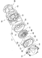
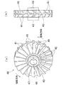
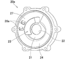
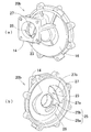
以下、本発明の実施の形態における自吸式ポンプを図面に基づいて説明する。図1は、自吸式ポンプの分解斜視図である。図2は、自吸式ポンプの横断面図である。図3は、第1中間ケーシングの斜視図である。図4は、第2中間ケーシングの斜視図である。図5は、インペラの(a)斜視図、(b)右側面図である。図6は、インペラの一部破断斜視図である。図7は、自吸式ポンプの一部断面左側面図である。図8は、自吸式ポンプの作動状態を示す縦断面図である。図9は、別実施例における第1中間ケーシングの斜視図である。図10は、さらに別実施例における第1中間ケーシングの斜視図である。 Hereinafter, the self-priming pump according to the embodiment of the present invention will be described with reference to the drawings. FIG. 1 is an exploded perspective view of a self-priming pump. FIG. 2 is a cross-sectional view of the self-priming pump. FIG. 3 is a perspective view of the first intermediate casing. FIG. 4 is a perspective view of the second intermediate casing. FIG. 5 is a perspective view (a) and a right side view (b) of the impeller. FIG. 6 is a partially cutaway perspective view of the impeller. FIG. 7 is a left side view of a partial cross section of the self-priming pump. FIG. 8 is a vertical cross-sectional view showing an operating state of the self-priming pump. FIG. 9 is a perspective view of the first intermediate casing in another embodiment. FIG. 10 is a perspective view of the first intermediate casing in still another embodiment.
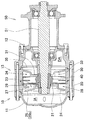
当該自吸式ポンプは、図1及び図2に示すように、ケーシングにおける吸入側室側の流路と吐出側室側の流路とが直列接続されるものである。当該自吸式ポンプにおいて、ケーシングにおける吸入側室側を前方とし、吐出側室側を後方とする。 In the self-priming pump, as shown in FIGS. 1 and 2, the flow path on the suction side chamber side and the flow path on the discharge side chamber side of the casing are connected in series. In the self-priming pump, the suction side chamber side of the casing is the front and the discharge side chamber side is the rear.
本発明の実施例に係る自吸式ポンプは、図1及び図2に示すように、主に、流体の吸入口14及び吐出口15を有するケーシング10と、ケーシング10内部に設置されるインペラ40と、インペラ40を回転駆動させる駆動部50とを備えて構成される。
As shown in FIGS. 1 and 2, the self-priming pump according to the embodiment of the present invention mainly includes a
ケーシング10は、図1及び図2に示すように、前壁11と後壁12とを連結する周壁13とから構成され、中空の略円筒状に形成される。また、前壁11には、外側方向に向けて開口される吸入口14が設けられ、後壁12には、同様にして外側方向に向けて形成される吐出口15が設けられる。また、本実施例においては、吸入口14と吐出口15とは同方向に開口するよう設けられるが、これに限られるものではない。
As shown in FIGS. 1 and 2, the
また、後壁12には、前壁11側に向かって延びる出力軸51が挿通されてなる。当該出力軸51には駆動部50が連結されており、これにより後述のインペラ40は回転自在とされる。また、出力軸51には、後壁12との間にシール部材(図示しない)が設けられる。その他、駆動部50については従来と同様であるので、その説明を省略する。
Further, an
また、ケーシング10内においては、吸入口14側に出力軸51が挿通される第1内部壁21が前方側の周壁13に設置されるとともに、吐出口15側に出力軸51が挿通される第2内部壁31が後方側の周壁13に設置される。また、第1内部壁21と第2内部壁31との間には、出力軸51により回転自在となるインペラ40が固定される。これにより、ケーシング10内は、吸入口14から第1内部壁21に至るまでの吸入側室IAと、第2内部壁31から吐出口15に至るまでの吐出側室DAとにそれぞれ区画される。すなわち、ケーシング10内において、吸入側室IAと吐出側室DAとが直列に配置される。
Further, in the
本実施例においては、ケーシング10は、前方ケーシング16と、中間ケーシング17及び後方ケーシング18とから構成される。当該ケーシング10は、これらがボルト等の固定手段により連結することで構成される。
In this embodiment, the
前方ケーシング16は、前方側が前壁11により閉塞されるとともに、後方側が開口してなり、当該周壁には外側に向けて開口される吸入口14が設けられる。また、中間ケーシング17は、第1中間ケーシング20と第2中間ケーシング30とから構成され、第1中間ケーシング20と第2中間ケーシング30との間にインペラ40が収容される。第1中間ケーシング20と第2中間ケーシング30の内径は、インペラ40が回転可能となるよう、インペラ40の外径と略同径となるよう形成される。このとき、流体とインペラ40との摩擦力を向上させるため、両ケーシング20、30の内径とインペラ40の外径との間隙を微小なものとすることが望ましい。
The
また、後方ケーシング18は、後方側が後壁12により閉塞されるとともに、前方側が開口してなり、当該周壁には外側に向けて開口される吐出口15が設けられる。また、後壁12には、前方側に向かって延びる出力軸51が挿通されてなり、後方ケーシング18の後方側に位置する出力軸51には駆動部50が設置される。
Further, the
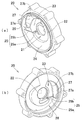
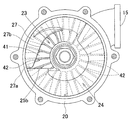
第1中間ケーシング20は、図1及び図3に示すように、インペラ40の前方側におけるケーシング10内にて吸入側室IAを区画形成する第1内部壁21が設けられる。当該第1内部壁21は、略中央部に出力軸51が挿通される貫通孔22が形成され、出力軸51の近傍には吸入孔23が形成される。当該吸入孔23は、インペラ40の回転によって流体を吸入するため、吸入側室IA側からみて貫通孔22の左上領域に形成される。また、吸入孔23の中心位置は、貫通孔22の中心位置から所定距離だけ上方に偏心させ、この中心から上方の開口領域を減少させるようにして形成される。
As shown in FIGS. 1 and 3, the first
また、吸入側室IA側における第1内部壁21の端面には、インペラ40の回転によって生じる流体の流れに沿いながら、吸入孔23に向けて案内されるよう螺旋状の導水路24が形成される。当該導水路24は、吸入側室IA側からみて、吸入孔23の下方から反時計回り方向であって、貫通孔22の上方にかけて、第1中間ケーシング20の内径に沿って形成される。
Further, on the end surface of the first
また、吸入孔23における下方側の導水路24は、吸入孔23の開口領域を前方側へと拡開させるようにして、後述の受口部26を形成する開口壁部25が設けられる。すなわち、開口壁部25側から反時計回り方向の吸入孔23側にかけて、徐々にその深さが大きくなるようにして導水路24が形成される。
Further, the
本実施例においては、開口壁部25は、吸入孔23における近傍の端面から縦壁部25aが前方側へ突設され、当該縦壁部25aの前方端部と第1中間ケーシング20の内径とを連結するようにして横壁部25bが設けられている。これにより、吸入孔23を前方側へ大きく開口させた形状とし、受口部26を形成している。そして、受口部26を形成する横壁部25bにおける前方側の端面から反時計回り方向の貫通孔の上方にかけて、徐々にその深さが大きくなるように螺旋状の導水路24が形成される。
In the present embodiment, in the
また、第1中間ケーシング20には、第1中間ケーシング20の内径から貫通孔22側に向けて、吸入孔23の一部を隔てるようにして隔壁27が設けられる。当該隔壁27は、横壁部25bよりも後方に形成されており、これにより、横壁部25bと隔壁27との間に受口部26を形成している。このとき、インペラ40における前方側の端面から受口部26における横壁部25bの上端部までの寸法は、開口領域を確保し流体の流入量を増加させる観点から、少なくとも後述の間隔29の寸法より大きく設定されることが望ましい。
Further, the first
また、当該受口部26における横壁部25bの幅寸法は、図7に示すように、少なくともインペラ40における外周壁45の幅寸法よりも幅広に形成される。より好ましくは、横壁部25bの幅寸法は、吸入孔23の内側円弧線に近接するように形成される。これにより、受口部26の開口領域を大きくすることができるので、流体の流入量を増加させることができ、望ましい。
Further, as shown in FIG. 7, the width dimension of the
また、隔壁27は、インペラ40の外周壁45に対向する位置にて形成されており、隔壁27の下方端部27aは横壁部25bの上端部と略同等の位置となるよう形成される。これにより、図8に示すようにして、横壁部25bの上端部よりインペラ40側の下方側へと第2流路Yを形成することができ、後述する噴流によって、受口部26へと流体を流入させ易いものとすることができる。より詳細には、隔壁27の下方端部27aは、横壁部25bの上端部より上方位置となるよう形成される。係る際には、揚水性能が低下するものの、キャビテーションの発生を抑制することができる。また、隔壁27の下方端部27aは、横壁部25bの上端部と同等、若しくは当該上端部より下方位置となるよう形成される。係る際には、揚水性能を向上させることができるものの、キャビテーションが発生し易いものとなる。
The
また、隔壁の下方端部27aは、図7に示すように、先端にかけて幅狭状であって、下方に向けて凸状となるよう円弧状に形成されることが望ましい。これにより、キャビテーションの発生を抑制することができる。さらに、隔壁27の内側縁27bは、後述するインペラ40の外周壁45の内側縁に沿うよう、円弧状に形成されることが望ましい。すなわち、隔壁27の下方端部27aを横壁部25bの上端部より下方位置となるよう形成するとともに、隔壁27の下方端部27aを先端にかけて幅狭状であって、下方に向けて凸状となるよう円弧状に形成されることが望ましい。これにより、揚水性能を向上させるとともに、キャビテーションの発生を抑制することができる。
Further, as shown in FIG. 7, it is desirable that the
そして、インペラ40側における第1内部壁21の端面には、図3(b)に示すように、吸入孔23及び受口部26から取り込まれた流体を加圧しながら移送するよう略U字状の移送溝28が形成される。当該移送溝28は、上方が受口部26に連通するよう形成されるとともに、流体を効率よく移送させるために、吸入孔23側の一端から他端にかけて、溝の深さが小さくなるよう設定される。具体的には、移送溝28は、一端が受口部26に連通して形成され、他端に向けて徐々に溝の深さが小さくなるよう設定される流路が連続することで形成される。
Then, as shown in FIG. 3 (b), the fluid taken in from the
すなわち、吸入側室IA側における第1内部壁21においては、略中央部に出力軸51が挿通される貫通孔22の端面より前方側に受口部26を形成する開口壁部25を設けることで、当該開口壁部25から吸入孔23側に向けて案内されるよう螺旋状の導水路24が形成されるとともに、インペラ40の外周壁45に対向する位置にて吸入孔23の一部を隔てる隔壁27が連続して形成されるものである。このようにして形成される第1内部壁21は、図7に示すように、吸入側室IA側からみて、インペラ40の外周壁45に対向する位置にて、導水路24及び隔壁27が連続して形成されるとともに、インペラ40の開口部42に対向する位置にて、吸入孔23が形成されるものである。
That is, in the first
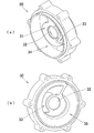
第2中間ケーシング30は、図1及び図4に示すように、インペラ40の後方側におけるケーシング10内にて吐出側室DAを区画形成する第2内部壁31が設けられる。当該第2内部壁31は、略中央部に出力軸51が挿通される貫通孔32が形成され、第1内部壁21の吸入孔23と左右対称となる位置に吐出孔33が形成される。また、吐出孔33の中心位置は、貫通孔32の中心位置と略同等に位置してなり、例えば、この中心から上方の開口領域を減少させるようにして形成される。
As shown in FIGS. 1 and 4, the second
また、図4(a)に示すように、第2内部壁31における吸入側室IA側の端面には、吸入側室IA側から取り込まれた流体を加圧しながら移送するよう略U字状の移送溝34が形成される。当該移送溝34は、同様にして上方が閉塞するよう形成されるとともに、流体を効率よく移送させるために、吐出孔33側に対向位置する一端から他端にかけて、溝の深さが小さくなるよう設定される。
Further, as shown in FIG. 4A, a substantially U-shaped transfer groove is formed on the end surface of the second
また、同図(b)に示すように、第2内部壁31における吐出側室DA側の端面には、インペラ40の回転によって生じる流体の流れに沿いながら、吐出孔33から排出されるよう螺旋状の導水路35が形成される。
Further, as shown in FIG. 3B, the end surface of the second
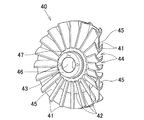
インペラ40は、複数の羽根部41に開口部42を有してなり、直列配置される吸入側室IAと吐出側室DAにおいて、吸入側室IA側の流体を吐出側室DA側へと送り込むものである。具体的には、インペラ40は、基部43を中心として放射状に延び、回転方向側に流体を取り込む開放空間44を形成してなる羽根部41と、羽根部41の先端部相互を連結し、基部43との間の所定領域に開口部42を形成する外周壁45とを有してなるものである。
The
本実施例においては、図5に示すように、インペラ40は、基部43を中心として放射状に延びる複数の羽根部41を有してなる。当該基部43には、出力軸51を挿通するための貫通孔46が形成され、当該貫通孔46には出力軸51を結合するためのキー溝47が形成される。
In this embodiment, as shown in FIG. 5, the
羽根部41は、基部43における幅寸法と略同等の長さ寸法を有してなり、インペラ40の回転方向側に開放空間44が形成されるよう円弧状に形成され、所定の間隔をもって、基部43における外周の全面に亘って設けられる。また、インペラ40には、隣接する相互の羽根部41を連結するように外周壁45が設けられる。当該外周壁45は、基部43における幅方向の略中央部に位置し、羽根部41の先端側を略二等分するようにして設けられる。これによって、基部43と外周壁45との間の所定領域に開口部42が形成される。
The
また、インペラ40は、従来と同様にして、インペラの反回転方向側に傾斜し、基部の前縁側に位置する第1羽根(図示しない)と、基部の後縁側に位置する第2羽根(図示しない)とを連結させ、基部側の所定領域に開口部を有する構成とすることができるのは勿論である。
Further, the
逆流防止機構は、吐出側室DA側から吸入側室IA側へと流体が逆流するのを防止又は抑制するものである。当該逆流防止機構は、公知の接触形シール部、非接触形シール部等を採用することができる。 The backflow prevention mechanism prevents or suppresses the backflow of the fluid from the discharge side chamber DA side to the suction side chamber IA side. As the backflow prevention mechanism, a known contact type seal portion, non-contact type seal portion, or the like can be adopted.
具体的には、図2に示すように、インペラ40の基部43に第1内部壁21の挿通孔22を挿通するボス状とし、当該基部43の外周に当該挿通孔22との境界に接触形シール部(図示しない)を設けることで構成される。接触形シール部には、例えば、メカニカルシール、リップパッキン等の成形パッキン、グランドパッキン等を採用することができる。これにより、インペラ40と第1内部壁21との前後方向の間隙から基部43に沿って吸入側室IA側へと逆流するのを抑制することができる。
Specifically, as shown in FIG. 2, a boss shape is formed in which the
また、基部43の外周及び第1内部壁21の挿通孔22に非接触形シール(図示しない)を設けることもできる。非接触形シール部には、例えば、ラビリンスシール等を採用することができる。これにより、接触形シール部と同様にして、吸入側室IA側へと逆流するのを抑制することができる。
Further, a non-contact seal (not shown) may be provided on the outer periphery of the
このようにして構成される自吸式ポンプは、図1及び図2に示すように、中間ケーシング17における第1内部壁21と第2内部壁31の間にて、インペラ40が出力軸51に回転自在に連結される。このとき、吸入孔23と吐出孔33が左右対称となるよう配置される。
In the self-priming pump configured in this way, as shown in FIGS. 1 and 2, the
また、図7に示すように、第1内部壁21の吸入孔23及び隔壁27とインペラ40の開口部42との関係においては、吸入孔23の内側円弧線が基部43の外周線に一致する、又は外周線より外径方向に位置するよう設定される。また、隔壁27における円弧状の内側縁27bを投影させた位置に開口部42の外側線の少なくとも一部が重合するよう設定される。これにより、吸入孔23から流路にかけての流体を案内しやすいものとすることができる。また、第2内部壁31の吐出孔33とインペラ40の開口部42との関係においても同様である。
Further, as shown in FIG. 7, in the relationship between the
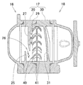
当該自吸式ポンプの作動について、図2、図7及び図8に基づいて以下に説明する。自吸式ポンプは、通常運転となる揚水運転と、起動開始から揚水運転へ移行するまでの自吸運転とを行う。当該自吸運転においては、インペラ40が図7の反時計回り方向(図8中手前方向から奥方向)に回転することで、吸入側室IA側に負圧がかかりながら内部の流体(気液混合水)がインペラ40に吸い込まれ、インペラ40の遠心力と摩擦力によって、流路から吐出側室DA側へと吐出される。このようなインペラ40によって流体内に空気が取り込まれ、流体と空気が混合された気液混合水を吐出する自吸運転においては、従来と同様であるので、その説明を省略する。
The operation of the self-priming pump will be described below with reference to FIGS. 2, 7 and 8. The self-priming pump performs a pumping operation, which is a normal operation, and a self-priming operation from the start to the transition to the pumping operation. In the self-priming operation, the
また、揚水運転については、自吸運転における気液混合水が吐出され、空気が混合されることのない流体のみの状態となり、自吸運転と同様にして、インペラ40の回転により、吸入側室IA側から吐出側室DA側へと吐出される。
Further, in the pumping operation, the gas-liquid mixed water in the self-priming operation is discharged, and only the fluid in which the air is not mixed is discharged. In the same manner as in the self-priming operation, the rotation of the
より詳細には、図8に示すように、回転するインペラ40の遠心力と摩擦力によって、流体は中間ケーシング17内の外径方向へと運ばれ、隔壁27とインペラ40との間隔29にて、前方側の羽根部41との摩擦により第1流路Xを形成し、吸入孔23側から吐出孔33側へと反時計回り方向に運ばれる。このとき、第1流路Xにおいては、隔壁27とインペラ40との間の所定の間隔29を介し、当該間隔29内の流体を加速させて噴流を発生されることができ、当該噴流によって発生する負圧によって、流体の残部を開口壁部25と隔壁27との間に形成される受口部26から第2流路Yへと呼び込むことができる。これにより、揚水性能の向上を図ることができ、吐出流量を向上させることができる。
More specifically, as shown in FIG. 8, by the centrifugal force and frictional force of the rotating
後に、インペラ40側における第1内部壁21の端面においては、移送溝28が徐々に溝の深さが小さくなるように設定されているため、これにより流体が押し出されて、インペラ40の開口部42を介して後方側へと流れ込む。
Later, on the end surface of the first
そして、インペラ40の後方側においては、同様にして、流体が回転するインペラ40の後方側の羽根部41との摩擦により、第2内部壁31の移送溝34へと運ばれる。そして、移送溝34内の流体は、反時計回り方向に運ばれ、当該移送溝34が徐々に溝の深さが小さくなるよう設定されているため、流体は加圧されながら圧送され、吐出孔33から吐出側室DA側へと吐出される。
Then, on the rear side of the
以上、説明した本発明に係る自吸式ポンプによれば、吸入口14が設けられるケーシング10の吸入側室IAは、流体をインペラ40側へと流入させる吸入孔23と、インペラ40の外周壁44に対向し、インペラ40との間に所定の間隔29を形成する隔壁27とを有してなるので、インペラ40の回転により、第1流路Xとなる間隔29内の流体を加速させて噴流を発生させることができる。これにより、従来のように吸入孔の開口領域が小さくなってしまう場合であっても、当該噴流の負圧によって流体の残部を開口壁部25と隔壁27との間に形成される受口部26から第2流路Yへと呼び込んで吸入することができる。結果として、揚水性能の向上を図ることができ、吐出流量を向上させることができる。
According to the self-priming pump according to the present invention described above, the suction side chamber IA of the
また、上述した実施例において、第1中間ケーシング20、第2中間ケーシング30、インペラ40を構成する羽根部41の形状、寸法、材質等を適宜変更して実施することが可能である。第1中間ケーシング20の開口壁部25においては、縦壁部25a及び横壁部25bから構成されるものであったが、これに限られるものではない。例えば、縦壁部25a及び横壁部25bを一連の円弧状の壁部から構成することもできるし、これに限られない。すなわち、隔壁27の前方側にて開口領域を形成し、隔壁27との間で受口部26を形成するよう開口壁部25が形成されていればよい趣旨である。
Further, in the above-described embodiment, the shape, dimensions, material, etc. of the
また、第1中間ケーシング20の受口部26においては、開口壁部25を設けることで隔壁27との間に形成するものであったが、これに限られるものではない。例えば、図9に示すように、第1内部壁21の略中央部に出力軸51が挿通される貫通孔22が形成され、当該貫通孔22の左上領域に吸入孔23が形成される第1中間ケーシング20aにおいて、吸入孔23に向けて案内されるよう螺旋状の導水路24と、吸入孔23の外径方向に位置する隔壁27とを連続して形成することもできる。
Further, the receiving
係る際に、第1中間ケーシング20aにおいては、隔壁27にインペラ40側へと貫通する受口部26aが形成される。当該受口部26aは、複数個を設けることができるのは勿論である。また、隔壁27には、流体の流速が急激に変化するのを防止するため、受口部26aに繋がるテーパ面を有することが望ましい。
At this time, in the first
これにより、インペラ40の回転により、隔壁27とインペラ40との間における第1流路Xとなる間隔29内の流体を加速させて噴流を発生させることができ、当該噴流の負圧によって流体の残部を隔壁27の受口部26aから呼び込んで吸入することができる。その他の作用、効果については、開口壁部25と隔壁27にて受口部26を形成するものと同様である。すなわち、開口壁部25と隔壁27による受口部26を形成することなく、同様の効果を奏することができる。
As a result, the rotation of the
また、第1中間ケーシング20における開口壁部25、受口部26、隔壁27等は、第1内部壁21に形成されるものであったが、これに限られるものではない。例えば、これらは、ケーシング10の吸入側室IA内に形成されるものであれば、その設置箇所は特に制限されるものではない。上記実施例においては、自吸式ポンプの構造を簡略化させるために、これらが第1内部壁21に形成されるものである。また、第2中間ケーシング30の第2内部壁31についても同様である。
Further, the opening
より具体的には、図10に示すように、吸入口14から吸入される流体が吸入孔23、受口部26へと直接流入されるよう、前壁16を備える第1中間ケーシング20bを構成することもできる。係る際には、上記実施例における導水路24が形成されることなく、自吸式ポンプの構造をより簡略化することができる。
More specifically, as shown in FIG. 10, the first
また、自吸式ポンプにおいては、ケーシング10における吐出側室DA側を前方側に設置し、吸入側室IA側を後方側に設置することができるのは勿論である。
Further, in the self-priming pump, it is of course possible to install the discharge side chamber DA side of the
更に、一部構成を省略することができるし、一部抽出した構成とすることができるのは勿論である。 Further, it is needless to say that a partial configuration can be omitted and a partially extracted configuration can be used.
10 ケーシング
14 吸入口
15 吐出口
23 吸入孔
25 開口壁部
26、26a 受口部
27 隔壁
29 間隔
40 インペラ
41 羽根部
42 開口部
43 基部
44 開放空間
45 外周壁
50 駆動部
X 第1流路
Y 第2流路
IA 吸入側室
DA 吐出側室
10
Claims (4)
前記インペラは、基部を中心として放射状に延び、回転方向側に前記流体を取り込む開放空間を形成してなる羽根部と、前記羽根部の先端部相互を連結し、前記基部との間の所定領域に開口部を形成する外周壁とを有し、
前記吸入口が設けられる前記ケーシングの吸入側室は、前記流体を前記インペラ側へと流入させる吸入孔と、前記インペラの前記外周壁に対向し、前記インペラとの間に所定の間隔を形成する隔壁とを有してなり、
前記インペラの回転により、前記間隔内の前記流体を加速させて噴流を発生させ、前記噴流によって発生する負圧によって前記流体の残部を呼び込んで吸入することを特徴とする自吸式ポンプ。 A self-priming pump including a casing having a fluid suction port and a discharge port, an impeller installed inside the casing, and a drive unit for rotationally driving the impeller.
The impeller extends radially around the base portion to form an open space for taking in the fluid on the rotation direction side, and connects the tip portions of the blade portions to each other to form a predetermined region between the base portion. Has an outer wall that forms an opening in
The suction side chamber of the casing provided with the suction port is a partition wall that faces the suction hole for allowing the fluid to flow into the impeller side and the outer peripheral wall of the impeller and forms a predetermined distance between the impeller. And have
A self-priming pump characterized in that the rotation of the impeller accelerates the fluid within the interval to generate a jet, and the negative pressure generated by the jet attracts and sucks the rest of the fluid.
Priority Applications (1)
| Application Number | Priority Date | Filing Date | Title |
|---|---|---|---|
| JP2016128276A JP6775813B2 (en) | 2016-06-29 | 2016-06-29 | Self-priming pump |
Applications Claiming Priority (1)
| Application Number | Priority Date | Filing Date | Title |
|---|---|---|---|
| JP2016128276A JP6775813B2 (en) | 2016-06-29 | 2016-06-29 | Self-priming pump |
Publications (2)
| Publication Number | Publication Date |
|---|---|
| JP2018003638A JP2018003638A (en) | 2018-01-11 |
| JP6775813B2 true JP6775813B2 (en) | 2020-10-28 |
Family
ID=60948768
Family Applications (1)
| Application Number | Title | Priority Date | Filing Date |
|---|---|---|---|
| JP2016128276A Expired - Fee Related JP6775813B2 (en) | 2016-06-29 | 2016-06-29 | Self-priming pump |
Country Status (1)
| Country | Link |
|---|---|
| JP (1) | JP6775813B2 (en) |
Families Citing this family (3)
| Publication number | Priority date | Publication date | Assignee | Title |
|---|---|---|---|---|
| CN108286524B (en) * | 2018-03-31 | 2023-12-29 | 浙江日井泵业股份有限公司 | Pipeline pump with self-priming function |
| CN109538522B (en) * | 2018-10-30 | 2020-05-12 | 浙江水利水电学院 | Connecting structure and mounting method for inducer, centrifugal wheel and rotor |
| CN111059057B (en) * | 2019-12-24 | 2021-08-06 | 浙江水利水电学院 | Anti-cavitation centrifugal pump and manufacturing method thereof |
Family Cites Families (3)
| Publication number | Priority date | Publication date | Assignee | Title |
|---|---|---|---|---|
| US6126387A (en) * | 1996-08-26 | 2000-10-03 | Aisan Kogyo Kabushiki Kaisha | Fuel pump having low operating noise |
| JP3756337B2 (en) * | 1999-02-09 | 2006-03-15 | 愛三工業株式会社 | Fluid pump |
| JP6229514B2 (en) * | 2014-01-28 | 2017-11-15 | 近畿金属株式会社 | Self-priming pump |
-
2016
- 2016-06-29 JP JP2016128276A patent/JP6775813B2/en not_active Expired - Fee Related
Also Published As
| Publication number | Publication date |
|---|---|
| JP2018003638A (en) | 2018-01-11 |
Similar Documents
| Publication | Publication Date | Title |
|---|---|---|
| CN101849110B (en) | Side channel compressor | |
| JP6229514B2 (en) | Self-priming pump | |
| CN104813082B (en) | Seals and rotating machinery | |
| JP5384322B2 (en) | Pump impeller and submersible pump equipped with the impeller | |
| JP6117659B2 (en) | Centrifugal pump | |
| JP6775813B2 (en) | Self-priming pump | |
| EP2899405A1 (en) | Rotary machine | |
| JP5256184B2 (en) | Counter-rotating axial fan | |
| JP2019035374A (en) | Centrifugal rotating machine | |
| JP6690900B2 (en) | Fluid machinery | |
| JP6802770B2 (en) | Fluid machine | |
| JP4724610B2 (en) | Gas separation device, its front wall and separation rotor | |
| JP2016065530A (en) | Water pump with impeller | |
| JP2010025041A (en) | Centrifugal fluid machine | |
| JP2012072695A (en) | Centrifugal pump | |
| JP2013057275A (en) | Centrifugal pump | |
| JP5268700B2 (en) | Pump and Western-style toilet using the same | |
| JP6849988B2 (en) | Self-priming pump | |
| JP6740070B2 (en) | Fluid machinery | |
| JP5748505B2 (en) | Rotating machine | |
| KR20220099758A (en) | Pump | |
| JP4819620B2 (en) | Self-priming pump | |
| KR101289519B1 (en) | Fish pump | |
| JP2008101553A (en) | Impeller of water pump | |
| JP4819621B2 (en) | Non-displacement pump |
Legal Events
| Date | Code | Title | Description |
|---|---|---|---|
| A621 | Written request for application examination |
Free format text: JAPANESE INTERMEDIATE CODE: A621 Effective date: 20190612 |
|
| A977 | Report on retrieval |
Free format text: JAPANESE INTERMEDIATE CODE: A971007 Effective date: 20200423 |
|
| A131 | Notification of reasons for refusal |
Free format text: JAPANESE INTERMEDIATE CODE: A131 Effective date: 20200609 |
|
| A521 | Request for written amendment filed |
Free format text: JAPANESE INTERMEDIATE CODE: A523 Effective date: 20200707 |
|
| TRDD | Decision of grant or rejection written | ||
| A01 | Written decision to grant a patent or to grant a registration (utility model) |
Free format text: JAPANESE INTERMEDIATE CODE: A01 Effective date: 20200819 |
|
| A61 | First payment of annual fees (during grant procedure) |
Free format text: JAPANESE INTERMEDIATE CODE: A61 Effective date: 20200930 |
|
| R150 | Certificate of patent or registration of utility model |
Ref document number: 6775813 Country of ref document: JP Free format text: JAPANESE INTERMEDIATE CODE: R150 |
|
| R250 | Receipt of annual fees |
Free format text: JAPANESE INTERMEDIATE CODE: R250 |
|
| LAPS | Cancellation because of no payment of annual fees |