JP6774959B2 - Adjustable sleep apnea oral device - Google Patents
Adjustable sleep apnea oral device Download PDFInfo
- Publication number
- JP6774959B2 JP6774959B2 JP2017551571A JP2017551571A JP6774959B2 JP 6774959 B2 JP6774959 B2 JP 6774959B2 JP 2017551571 A JP2017551571 A JP 2017551571A JP 2017551571 A JP2017551571 A JP 2017551571A JP 6774959 B2 JP6774959 B2 JP 6774959B2
- Authority
- JP
- Japan
- Prior art keywords
- tray
- pad
- meshing
- anchor
- subject
- Prior art date
- Legal status (The legal status is an assumption and is not a legal conclusion. Google has not performed a legal analysis and makes no representation as to the accuracy of the status listed.)
- Active
Links
Images


Classifications
-
- A—HUMAN NECESSITIES
- A61—MEDICAL OR VETERINARY SCIENCE; HYGIENE
- A61C—DENTISTRY; APPARATUS OR METHODS FOR ORAL OR DENTAL HYGIENE
- A61C7/00—Orthodontics, i.e. obtaining or maintaining the desired position of teeth, e.g. by straightening, evening, regulating, separating, or by correcting malocclusions
- A61C7/08—Mouthpiece-type retainers or positioners, e.g. for both the lower and upper arch
-
- A—HUMAN NECESSITIES
- A61—MEDICAL OR VETERINARY SCIENCE; HYGIENE
- A61C—DENTISTRY; APPARATUS OR METHODS FOR ORAL OR DENTAL HYGIENE
- A61C7/00—Orthodontics, i.e. obtaining or maintaining the desired position of teeth, e.g. by straightening, evening, regulating, separating, or by correcting malocclusions
- A61C7/36—Devices acting between upper and lower teeth
-
- A—HUMAN NECESSITIES
- A61—MEDICAL OR VETERINARY SCIENCE; HYGIENE
- A61F—FILTERS IMPLANTABLE INTO BLOOD VESSELS; PROSTHESES; DEVICES PROVIDING PATENCY TO, OR PREVENTING COLLAPSING OF, TUBULAR STRUCTURES OF THE BODY, e.g. STENTS; ORTHOPAEDIC, NURSING OR CONTRACEPTIVE DEVICES; FOMENTATION; TREATMENT OR PROTECTION OF EYES OR EARS; BANDAGES, DRESSINGS OR ABSORBENT PADS; FIRST-AID KITS
- A61F5/00—Orthopaedic methods or devices for non-surgical treatment of bones or joints; Nursing devices; Anti-rape devices
- A61F5/56—Devices for preventing snoring
- A61F5/566—Intra-oral devices
Description
[関連出願の相互参照]
本出願は、35U.S.C.§120に基づいて2014年12月16日に出願された「ADJUSTABLE SLEEP APNEA ORAL APPLIANCE(調節可能な睡眠時無呼吸用口腔内装置)」と題する米国特許出願第62092761号より、米国特許法第120条の下でこの出願に基づく優先権の利益を主張する。上述の出願の開示は、その全体が参照として本明細書に組み込まれる。
[Cross-reference of related applications]
This application is based on 35 U.S.A. S. C. U.S. Patent Law No. 120 from U.S. Patent Application No. 62092761 entitled "ADJUSTABLE SLEEP APNEA ORAL APPLIANCE" filed on December 16, 2014 under §120. Claim the benefit of priority under this application under Article. The disclosure of the above application is incorporated herein by reference in its entirety.
睡眠時無呼吸は、睡眠中の異常な呼吸停止、又は異常に低い呼吸という例を特徴とする疾患である。無呼吸と称される呼吸停止の各々は、数秒から数分続くことがあり(通常、20〜40秒続く)、1時間に5〜30回以上発生することがある。睡眠時無呼吸は、対象者の気道の不完全から完全な塞がりから生じる。気道を通る空気の速度の増加は、動圧の増加と、対応して静圧の減少を引き起こす。場合によっては、静圧の減少により下顎と舌とが引っ込み、そのことにより気道を塞いでしまう。この塞ぎが、完全になるところまで増加してくると、そこで少なくとも一時的に呼吸が中断され得る。 Sleep apnea is a disorder characterized by abnormal respiratory arrest during sleep, or abnormally low breathing. Each of the respiratory arrests, referred to as apnea, can last from a few seconds to a few minutes (usually lasting 20-40 seconds) and can occur 5 to 30 times or more per hour. Sleep apnea results from incomplete or complete obstruction of the subject's airways. An increase in the velocity of air through the airways causes an increase in dynamic pressure and a corresponding decrease in static pressure. In some cases, the decrease in static pressure causes the mandible and tongue to retract, thereby blocking the airways. When this blockage increases to perfection, breathing can be interrupted at least temporarily there.
対象者が肥満である、又は糖尿病、高血圧、又は慢性の鼻づまり等の状態を有する場合、対象者は一般的に睡眠時無呼吸の危険性がより高くなる。しかしながら、睡眠時無呼吸をもたらし得る要因は様々である。1つの要因は、対象者における狭い上顎及び/又は下顎の存在である。上顎の狭搾は、鼻腔抵抗が増加して舌の位置が代わり、舌後方の気道の狭窄をもたらす。上顎及び/又は下顎の狭搾は、一般的に口腔内の空気量を低減し、後方の気道空間に舌を押しやる傾向があり、睡眠中に閉塞性睡眠時無呼吸をもたらす。 If the subject is obese or has conditions such as diabetes, hypertension, or chronic nasal congestion, the subject is generally at greater risk of sleep apnea. However, there are various factors that can lead to sleep apnea. One factor is the presence of a narrow maxilla and / or mandible in the subject. Maxillary stenosis increases nasal resistance and alters the position of the tongue, resulting in narrowing of the airways behind the tongue. Narrowing of the maxilla and / or mandible generally reduces the amount of air in the oral cavity and tends to push the tongue into the posterior airway space, resulting in obstructive sleep apnea during sleep.
歯科矯正は歯科医学の分野で、例えば対象者の歯の「過密」を起因とする美的又は他の理由による対象者の歯及び顎の再配置に焦点をあてたものである。歯科矯正の方法では、結果を達成すべく、通常、対象者は歯科用装置を一定期間継続的に使用することが必要である。そのような装置を使用すると、睡眠時無呼吸を治療するための現在入手可能な口腔内装置との同時使用ができない。従って、睡眠時無呼吸を持つ歯科矯正装置の使用者において睡眠時無呼吸を治療するための改良型装置及び方法の必要性が残っている。 Orthodontics is in the field of dentistry, focusing on the repositioning of a subject's teeth and jaw for aesthetic or other reasons, for example due to "overcrowding" of the subject's teeth. Orthodontic methods usually require the subject to continue to use the dental device for a period of time in order to achieve results. The use of such devices does not allow simultaneous use with currently available intraoral devices for the treatment of sleep apnea. Therefore, there remains a need for improved devices and methods for treating sleep apnea in users of orthodontic appliances with sleep apnea.
本発明の口腔内装置は、上部トレー及び下部トレーを備え、それぞれが対象者におけるいびき及び/又は睡眠時無呼吸を治療し、対象者の歯科矯正の治療を成し遂げるよう構成される。一の実施形態において、上部トレーは以下(a)〜(f)を備える。
(a)上部トレーの内面によって囲まれた受け部
(b)上端で、上部トレーの右側の下面に連結された右側の上部噛み合わせ用パッドであって、噛み合わせ用パッドは、下面、前面、後面、右側、及び左側を備え、噛み合わせ用パッドは、上部トレーの右側の後方部分から前方に延在し、噛み合わせ用パッドの下面は、右側の上部トレーの前方部分の下部の冠状面よりも低い、右側の上部噛み合わせ用パッド
(c)上面、下面、前面、後面、右側、及び左側を備える右側のインサートであって、上面は、右側の上部噛み合わせ用パッドに対して前方に上部トレーの右側の下面に面し、及び/又は接触し、後面は、右側の上部噛み合わせ用パッドの前面に可逆的に取り付けられるように構成された右側のインサート
(d)上端で、上部トレーの左側の下面に連結された左側の上部噛み合わせ用パッドであって、噛み合わせ用パッドは、下面、前面、後面、右側、及び左側を備え、噛み合わせ用パッドは、上部トレーの左側の後方部分から前方に延在し、噛み合わせ用パッドの下面は、左側の上部トレーの前方部分の下部の冠状面よりも低い、左側の上部噛み合わせ用パッド
(e)上面、下面、前面、後面、右側、及び左側を備える左側のインサートであって、上面は、左側の上部噛み合わせ用パッドに対して前方に上部トレーの左側の下面に面し、及び/又は接触し、後面は、左側の上部噛み合わせ用パッドの前面に可逆的に取り付けられるように構成された左側のインサート
(f)上部トレーの右側の前方部分の外側の頬側面上の頬側に面する前方右側のアンカーと、上部トレーの左側の前方部分の外側の頬側面上の頬側に面する前方左側のアンカー
The intraoral device of the present invention comprises an upper tray and a lower tray, each of which is configured to treat snoring and / or sleep apnea in the subject and accomplish orthodontic treatment of the subject. In one embodiment, the upper tray comprises the following (a)-(f).
(A) A receiving portion surrounded by the inner surface of the upper tray (b) A right upper meshing pad connected to the lower surface on the right side of the upper tray at the upper end, and the meshing pad is the lower surface, the front surface, and the lower surface. It has a rear surface, a right side, and a left side, and the meshing pad extends forward from the rear part on the right side of the upper tray, and the lower surface of the meshing pad extends from the lower coronal surface of the front part of the upper tray on the right side. Low, right upper meshing pad (c) Right insert with top, bottom, front, rear, right, and left, with the top surface anteriorly superior to the right upper meshing pad. Facing and / or contacting the lower surface of the right side of the tray, the rear surface is the upper end of the right insert (d) configured to be reversibly attached to the front of the upper mating pad on the right side of the upper tray. The upper left upper meshing pad connected to the lower surface on the left side, the meshing pad includes the lower surface, the front surface, the rear surface, the right side, and the left side, and the meshing pad is the rear portion on the left side of the upper tray. The lower surface of the meshing pad extends forward from, and is lower than the lower coronal surface of the front part of the upper tray on the left side. Left upper meshing pad (e) Upper surface, lower surface, front surface, rear surface, right side , And a left insert with a left side, the top surface facing and / or contacting the left bottom surface of the upper tray anteriorly with respect to the left top meshing pad, and the rear surface facing the left top meshing pad. Left insert configured to be reversibly attached to the front of the mating pad (f) Front right anchor facing buccal on the outer buccal side of the right front part of the upper tray and the upper tray Anchor on the front left side facing the buccal side on the outer buccal side of the left front part
本実施形態において、下部トレーは以下(a)〜(e)を備える。
(a)上部トレーの内面によって囲まれた受け部
(b)下端で、下部トレーの右側の上面に連結された右側の下部噛み合わせ用パッドであって、噛み合わせ用パッドは、上面、前面、後面、右側、及び左側を備え、噛み合わせ用パッドは、下部トレーの右側の前方部分から後方に延在し、噛み合わせ用パッドの上面は、右側の下部トレーの後方部分の上部の冠状面よりも高い、右側の下部噛み合わせ用パッド
(c)下端で、上部トレーの左側の下面に連結された左側の下部噛み合わせ用パッドであって、噛み合わせ用パッドは、上面、前面、後面、右側、及び左側を備え、噛み合わせ用パッドは、下部トレーの左側の前方部分から後方に延在し、噛み合わせ用パッドの上面は、左側の下部トレーの後方部分の上部の冠状面よりも高い、左側の下部噛み合わせ用パッド
(d)下部トレーの右側の前方部分の外側の頬側面上の頬側に面する前方右側のアンカーと、下部トレーの左側の前方部分の外側の頬側面上の頬側に面する前方左側のアンカー
(e)下部トレーの右側の後方部分の外側の頬側面上の頬側に面する後方右側のアンカーと、下部トレーの左側の後方部分の外側の頬側面上の頬側に面する後方左側のアンカー
In this embodiment, the lower tray includes the following (a) to (e).
(A) A receiving portion surrounded by the inner surface of the upper tray (b) A lower right lower meshing pad connected to the upper surface on the right side of the lower tray at the lower end, and the meshing pads are the upper surface, the front surface, and the upper surface. It has a rear surface, a right side, and a left side, and the meshing pad extends rearward from the front part on the right side of the lower tray, and the upper surface of the meshing pad extends from the upper coronal surface of the rear part of the lower tray on the right side. Higher right lower meshing pad (c) The lower left lower meshing pad connected to the lower surface on the left side of the upper tray at the lower end, and the meshing pads are the upper surface, front surface, rear surface, and right side. The mating pad extends rearward from the front portion on the left side of the lower tray, and the top surface of the mating pad is higher than the coronal surface above the rear portion of the lower tray on the left side. Left lower bite pad (d) Front right anchor facing the buccal side on the outer buccal side of the right front part of the lower tray and cheek on the outer buccal side of the left front part of the lower tray Front left anchor facing the side (e) Rear right anchor facing the buccal side on the outer buccal side of the right rear part of the lower tray and on the outer buccal side of the left rear part of the lower tray Anchor on the rear left side facing the buccal side
上記の配置に伴い、右側のインサートの前面は、右側の下部噛み合わせ用パッドの後面に接触する係合面を形成し、左側のインサートの前面は、左側の下部噛み合わせ用パッドの後面に接触する係合面を形成する。このことは、上部トレーの下部トレーに対する前方への配置が制限され、したがって対象者による口腔内装置の使用時にいびき/無呼吸が緩和される。 With the above arrangement, the front surface of the right insert forms an engaging surface that contacts the rear surface of the right lower meshing pad, and the front surface of the left insert contacts the rear surface of the left lower meshing pad. Form an engaging surface. This limits the anterior placement of the upper tray with respect to the lower tray and thus alleviates snoring / apnea when the subject uses the intraoral device.
本発明の別の特有の特徴は、対象者の歯科矯正の治療を可能とし、同時にいびき及び/又は無呼吸を治療することである。一実施形態において、上部トレーの受け部、及び下部トレーの受け部はそれぞれ、歯科矯正トレー、好ましくは一連の歯科矯正トレーを受け入れて保持するように構成される。別の実施形態において、上部トレーの受け部、及び下部トレーの受け部はそれぞれ、対象者による装置の着用時に、対象者の1又はそれ以上の歯を再配置し、及び/又は対象者の上顎及び/又は下顎の構成を変えるように構成される。 Another unique feature of the present invention is to enable orthodontic treatment of the subject and at the same time treat snoring and / or apnea. In one embodiment, the receiving portion of the upper tray and the receiving portion of the lower tray are respectively configured to receive and hold an orthodontic tray, preferably a series of orthodontic trays. In another embodiment, the receiving portion of the upper tray and the receiving portion of the lower tray respectively rearrange one or more teeth of the subject and / or the upper jaw of the subject when the device is worn by the subject. And / or configured to alter the composition of the lower jaw.
代替的な実施形態において、上部噛み合わせ用パッド、及び下部噛み合わせ用パッドの位置は逆になり得るので、下部噛み合わせ用パッドは、下部トレーの後方部分に配置され、インサートは、下部噛み合わせ用パッドの前端に取り付けられ得る。この場合、上部噛み合わせ用パッドは前方に配置され、インサートの前面は、上部噛み合わせ用パッドの後面と係合する。 In an alternative embodiment, the positions of the upper meshing pad and the lower meshing pad can be reversed so that the lower meshing pad is located in the rear portion of the lower tray and the insert is in the lower meshing. Can be attached to the front end of the pad. In this case, the upper meshing pad is located forward and the front surface of the insert engages the rear surface of the upper meshing pad.
[定義]
本明細書で用いられるにあたり、以下の用語及びそれらの変形は、そのような用語が用いられる文脈によって異なる意味が明確に意図されない限り、以下に示す意味を有する。
[Definition]
As used herein, the following terms and variations thereof have the following meanings unless the context in which such terms are used is explicitly intended.
「アンカー」は、装置の一部分に固定され、その部分を装置の別の部分に連結するよう補助する本発明の装置の構成要素をいう。 "Anchor" refers to a component of a device of the invention that is fixed to one portion of the device and assists in connecting that portion to another portion of the device.
「前方」は、対象者の口の前部分(開口)の方向、対象者の口の前部分(開口)の方に向かう、又は対象者の口の前部分(開口)に隣接することを意味する。 "Front" means the direction of the front part (opening) of the subject's mouth, towards the front part (opening) of the subject's mouth, or adjacent to the front part (opening) of the subject's mouth. To do.
「いびき」及び「睡眠時無呼吸」は、一般的に対象者の気道が塞がって生じる、睡眠中の呼吸の一時的な停止、及び/又は浅い又は頻繁でない呼吸の事象をいう(閉塞性睡眠時無呼吸と称する)。 "Snoring" and "sleep apnea" generally refer to the temporary cessation of breathing during sleep and / or shallow or infrequent breathing events that occur when the subject's airways are blocked (obstructive sleep). Called sleep apnea).
「頬側」は、対象者の頬の方向、又は対象者の頬の方に向かうことを指す。対象者の歯に関して、頬側とは頬に面する歯の側を指す。 "Cheek side" refers to the direction of the subject's cheeks or toward the subject's cheeks. With respect to the subject's teeth, the buccal side refers to the side of the tooth facing the cheek.
「冠状面」は、頭から足までの身体を通り、身体を前半分と後半分とに分ける仮定の平面をいう。 "Coronal plane" refers to the hypothetical plane that passes through the body from head to foot and divides the body into front and rear halves.
「冠状」は、歯の遠位端(つまり、そしゃく面が位置するところ)上の又は歯の遠位端の方に向かう位置又は方向を指す。従って、冠状面は歯のそしゃく面であり、後方の歯では一般的に咬合面と呼ばれ、前方の歯では切歯面と呼ばれる。「冠状面」は、本発明の装置をユーザが着用する時に一方の歯科用トレーに接触する他方の歯科用トレーの対応する面、つまり上部の歯科用トレーの下面、又は下部の歯科用トレーの上面にも関する。 "Coronal" refers to a position or direction on the distal end of the tooth (ie, where the chewing surface is located) or towards the distal end of the tooth. Therefore, the coronal plane is the chewing plane of the tooth, which is generally called the occlusal plane in the posterior teeth and the incisor plane in the anterior teeth. The "coronal plane" is the corresponding surface of the other dental tray that comes into contact with one dental tray when the user wears the device of the invention, i.e. the lower surface of the upper dental tray, or the lower dental tray. Also related to the top surface.
「歯科用トレー」は、対象者の歯を受容する受け部を備える構造を指す。いくつかの実施形態において、受け部は、歯を受け入れるための開口、及び対象者の歯に直接接触する内面を有する。他の実施形態において、受け部は歯科矯正トレーを受け入れる。 "Dental tray" refers to a structure that includes a receiving portion that receives the subject's teeth. In some embodiments, the receiving portion has an opening for receiving the tooth and an inner surface that is in direct contact with the subject's tooth. In other embodiments, the receiver receives an orthodontic tray.
「下方」及び「下方に」は、対象者の身体の下部の方向、又は対象者の身体の下部の方に向かうことを意味する。「上方」及び「上方に」は、反対方向、つまり対象者の身体の上部の方向、又は対象者の身体の上部の方に向かうことを意味する。 "Down" and "down" mean towards the lower part of the subject's body or towards the lower part of the subject's body. "Upward" and "upward" mean toward the opposite direction, that is, toward the upper part of the subject's body, or toward the upper part of the subject's body.
「細長い」は、幅より長い長さを有する構成又は形状を指す。 "Elongated" refers to a configuration or shape that has a length longer than its width.
「前方へ」は、対象者の口の前方(前部)の方に向かう方向を意味する。 "Forward" means the direction toward the front (front) of the subject's mouth.
本発明の装置に対して「水平」とは、対象者の矢状面及び/又は冠状面にほぼ垂直な面、つまりそのような垂直面の15度以内への配置を指す。 "Horizontal" with respect to the device of the present invention refers to a plane substantially perpendicular to the sagittal and / or coronal planes of the subject, i.e., an arrangement of such vertical planes within 15 degrees.
「唇側」は、対象者の唇の方向、対象者の唇の方に向かう、又は対象者の唇に隣接することを意味する。対象者の歯に関して、唇側とは唇に面する前の歯の側を指す。 "Lip side" means the direction of the subject's lips, towards the subject's lips, or adjacent to the subject's lips. With respect to the subject's teeth, the labial side refers to the side of the tooth before facing the lips.
「側面」は、対象者の矢状面から離れることを意味する。 "Side" means away from the subject's sagittal plane.
「左」は、対象者から見て対象者の矢状面の左側を意味する。 "Left" means the left side of the subject's sagittal plane as viewed from the subject.
「舌側」は、対象者の舌の方向、対象者の舌の方に向かう、又は対象者の舌に隣接することを意味する。対象者の歯に関して、舌側とは舌に面する歯の側を指す。 "Lingual side" means the direction of the subject's tongue, towards the subject's tongue, or adjacent to the subject's tongue. With respect to the subject's teeth, the lingual side refers to the side of the tooth facing the tongue.
「下部」は、本発明の装置における構成要素の相対位置を指し、その構成要素が用いられる時に対象者の身体の下部の近く、又は対象者の身体の下部の方に向かっている。例えば、本発明の装置における上部トレーは、装置がユーザに着用されている時に、下部トレーより上(それより上方)に、つまり上部トレーが上顎歯列に嵌合し、下部トレーが下顎歯列に嵌合するように配置される。 "Lower" refers to the relative position of a component in the device of the invention, towards the lower part of the subject's body or towards the lower part of the subject's body when the component is used. For example, the upper tray in the device of the invention is above (above) the lower tray, that is, the upper tray fits into the maxillary dentition and the lower tray fits into the mandibular dentition when the device is worn by the user. Arranged to fit into.
「下顎の」は、下顎を指す。 "Mandibular" refers to the mandible.
「下顎歯列」は、下顎の歯を指す。 "Mandible dentition" refers to the teeth of the mandible.
「上顎の」は、上顎を指す。 "Maxillary" refers to the maxilla.
「上顎歯列」は、上顎の歯を指す。 "Maxillary dentition" refers to the maxillary teeth.
「機械的に連結された」は、直接的な物理的接触に基づいた連結を通じて、又は別の機械的構造を介してのいずれかで物理的に連結されることを意味する。 "Mechanically connected" means physically connected either through a connection based on direct physical contact or through another mechanical structure.
「中間の」は、対象者の中央の矢状面の方に向かうことを意味する。 "Middle" means heading towards the central sagittal plane of the subject.
「歯科矯正」は、対象者の歯、及び/又は顎の位置の再配置を行う機能又は装置を指す。 "Orthodontics" refers to a function or device that repositions a subject's teeth and / or jaws.
「歯科矯正トレー」は、対象者の上部歯列、又は下部歯列を受け入れるための歯科用トレーを指す。歯科矯正トレーの内面は、対象者の歯を受け入れる大きさであるソケット又は凹みで、対象者の歯と直接接触する。 "Orthodontic tray" refers to a dental tray for receiving the subject's upper or lower dentition. The inner surface of the orthodontic tray is a socket or recess sized to accommodate the subject's teeth and is in direct contact with the subject's teeth.
「柱」は、表面から突き出て、弾性バンド等の別の構成要素に対する接着点として作用する構成要素を指す。 "Column" refers to a component that protrudes from the surface and acts as an adhesion point to another component, such as an elastic band.
「後方(posterior)」及び「後方(rearward)」は、対象者の口の後方の方向、対象者の口の後方の方に向かう、又は対象者の口の後方に隣接することを意味する。 "Posterior" and "rearward" mean towards the back of the subject's mouth, towards the back of the subject's mouth, or adjacent to the back of the subject's mouth.
「右」は、対象者から見て、対象者の矢状面の右側を意味する。 "Right" means the right side of the subject's sagittal plane as viewed from the subject.
「矢状面」は、対象者の身体の上から下まで垂直に進み、対象者の身体を左部分と右部分とに分ける架空の平面を指す。 The "sagittal plane" refers to a fictitious plane that travels vertically from top to bottom of the subject's body and divides the subject's body into a left and right part.
「対象者」は、本発明の装置のユーザであって、通常は人間のユーザを指す。 A "subject" is a user of the device of the present invention, usually a human user.
「熱可塑性」は、材料で、一般的にポリマー材料を指し、可逆の物理過程において、加熱により軟化し、冷却により硬化し得る。本発明の装置のいくつかの構成要素に用いられる熱可塑性材料は、100°Fではその形状を保ち、好ましくは212°F以下で軟らかく(変形可能に)なる。 "Thermoplastic" is a material, generally referring to a polymeric material, which can be softened by heating and cured by cooling in a reversible physical process. The thermoplastic material used in some of the components of the apparatus of the present invention retains its shape at 100 ° F and is preferably soft (deformable) below 212 ° F.
本明細書で用いられる「トレー」及び「歯科用トレー」は、本発明の装置の概ねU字状の部分を指し、状況次第で対象者の上顎又は下顎の歯を受け入れるための開口領域を備える。 As used herein, a "tray" and a "dental tray" refer to a generally U-shaped portion of the device of the invention and, depending on the circumstances, includes an opening area for receiving the maxillary or lower jaw teeth of the subject. ..
「上部」は、本発明の装置における構成要素の相対位置であって、使用時に対象者の身体の上部の近く、又は対象者の身体の上部の方に向かっている相対位置を指す。 "Upper" refers to the relative position of a component in the device of the present invention, which is near the upper part of the subject's body or towards the upper part of the subject's body during use.
本発明の装置に対して「垂直」とは、対象者の矢状面及び/又は冠状面にほぼ平行な面、つまりそのような平行面の15度以内への配置を指す。好ましくは、垂直は対象者の頭又は脚の方に向かう、又は対象者の頭又は脚から離れる方向を指す。 "Vertical" with respect to the device of the present invention refers to a plane substantially parallel to the sagittal and / or coronal planes of the subject, i.e., an arrangement of such parallel planes within 15 degrees. Preferably, vertical refers to the direction towards the subject's head or legs, or away from the subject's head or legs.
「備える(comprise)」の用語、及び「備える(comprising)」、「備える(comprises)」等のその用語の変形は、他の付加物、構成要素、整数、又は工程を除外することを意図していない。本明細書で用いられる、「a」、「an」、及び「the」の用語、及び類似の指示語は、文脈においてそれらの使用が特定されない限りは、単数及び複数の両方を含むと解釈されるべきである。左や右といった相対語について、その用語は、他の向きが示されない場合、本発明の装置がユーザによって着用される時に、装置のユーザの視点からと解釈されるべきである。 The term "comprise" and variations of that term such as "comprising" and "comprises" are intended to exclude other additions, components, integers, or steps. Not. As used herein, the terms "a", "an", and "the", and similar demonstratives, are to be construed as including both singular and plural, unless their use is specified in the context. Should be. For relative terms such as left and right, the term should be construed from the user's point of view when the device of the invention is worn by the user, unless otherwise indicated.
[口腔内装置]
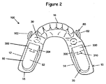
本発明の装置10は、一般的には一対の歯科用トレー15、上部トレー100、及び下部トレー200を備え、それらは睡眠時無呼吸を回避するように、協働して対象者の顎を位置づける。上部トレー100は対象者の上顎歯列に嵌合し、一方で下部トレー200は対象者の下顎歯列に嵌合する。本発明の装置のトレー部分15は、内面21、外面23、右側12、左側14、前方部分16、及び後方部分18を有し、トレー部分15のそれぞれが、対象者の歯列に適合するようトレー15の一方の水平側に形成された、概ねU字型の歯受容受け部20を備える。
[Intraoral device]
The
一実施形態において、受け部20は、対象者の歯を受け入れ、トレー15の内面21上で歯と接触するように構成される。受け部20は、側面の切れ目のない壁であって、その壁は対象者の歯の一部又は全部の頬側及び口唇側の一部又は全部を覆うように、対象者の歯の冠状面に面する底面から、それぞれ上顎又は下顎に向けて延在する、つまり頬側壁22及び唇側壁24を備える。以下で更に説明するように、トレー15は、対象者の既存の歯列に一致するように形成することができ、又は好ましい実施形態において、トレー15は、既存の歯列及び/又は対象者の上顎及び/又は下顎の形状の変更を実現するように形成され得る。
In one embodiment, the receiving
トレー15の外側部分は、受け部20と反対のトレーの水平側、つまりトレー15の外面23に形成された冠状面30を備える。各トレー15は、トレー15のそれぞれの側面に配置された一対の噛み合わせ用パッド35であって、下部噛み合わせ用パッド40又は上部噛み合わせ用パッド50のいずれかを更に備える。下部噛み合わせ用パッド40又は上部噛み合わせ用パッド50は、各トレー15と一体形成されてもよいし、各トレー15に結合されてもよい。図示した実施形態において、噛み合わせ用パッド35は、無呼吸の治療を補助すべく上顎と下顎とを離し、更に、上部トレー100の上部切端面101と、下部トレー200の下部切端面201との間に開口5を設けて空気が対象者の口を通るようにする。このように上顎及び下顎を離すことで対象者の口を若干空けた位置で維持することは、無呼吸を治療することも補助する。しかしながら、他の実施形態では、上部切端面101と下部切端面201は互いに接触してもよい。
The outer portion of the
図示した実施形態において、それぞれの下部噛み合わせ用パッド40は、下部トレー200の冠状面30に対して遠位に、つまり対象者が本発明の装置10を着用した時に上側に延在する突出部を備える。下部噛み合わせ用パッド40は、下部トレー200のそれぞれの側12、14の前方部分16、図示した実施形態におけるトレー200の下部冠状面30の前方に位置するが、(上部噛み合わせ用パッド50が前方に位置する)他の実施形態においては、下部噛み合わせ用パッド40は、比較的後ろの位置に位置してもよい。下部噛み合わせ用パッド40は、上部トレー100の前方部分の対応する冠状面30と接触するための、概ね水平の冠状面42を備える。下部噛み合わせ用パッド40は、噛み合わせ用パッド40の後方部分において後向きの係合面44を更に備え、これは冠状面42から下部トレー200の外面23の冠状面30に下方に延在する。
In the illustrated embodiment, each
上部トレー100は同様に、それぞれが上部トレー100の外面23から下方に延在する一対の上部噛み合わせ用パッド50を備える。上部噛み合わせ用パッド50は、下部トレー200の後方部分の対応する冠状面30と接触するための、概して水平の冠状面52と、上部噛み合わせ用パッド50の前方部分の前向きの接触面又は連結端54とを備える。それぞれの上部噛み合わせ用パッド50は、上部トレー100の冠状面30から遠位に、つまり対象者が本発明の装置10を着用した時に下方に延在し、下部トレー200の後方部分の対応する冠状面に接触するための概ね水平の冠状面52を含む、突出部を備える。本発明の装置10は、好ましくは、ユーザによる着用時に、上部噛み合わせ用パッド50の冠状面52が下部トレー200の後方部分の外側の冠状面30と接触し、同時に下部噛み合わせ用パッド40の冠状面42が上部トレー100の前方部分の冠状面30と接触するように構成される。
Similarly, the
本発明の口腔内装置10の独特の構成は、アキシャルインサート300の使用である。インサート300は、トレー15の一方に取り付け、本発明の装置10の他方のトレー15の噛み合わせ用パッド35と係合するように構成される。図示した実施形態において、インサート300は、上部トレー100に取り付けられ、下部トレーの下部噛み合わせ用パッド40と係合する。噛み合わせ用パッド35及びインサート300は、協働して、本発明の装置10のユーザの上顎及び下顎の相対的な前方―後方位置を限定及び規定する。図10から12に好例を示すように、それぞれのインサート300は、係合面302と、右側面304と、左側面306と、係合面302の反対側に取り付け端310とを備える。インサート300は、冠状面(上部トレー100に取り付けられる場合は下面)330と、冠状面330の反対側のトレー接触面(上面)332とを更に備える。インサート300の取り付け端310が上部トレーの連結端54と係合する場合、インサート300のトレー接触面は上部トレー100の冠状面30に接し、インサート300の冠状面330は外側に(下側に)向く。冠状面330は、好ましくは上部噛み合わせ用パッド50の冠状面52と平行であって、より好ましくは、同一の面に構成される。
A unique configuration of the
上部トレー100にインサート300を保持すべく、取り付け端310及び連結端54には、好ましくは相互に嵌る締め要素が設けられる。図示した実施形態において、インサート300の取り付け端310は、上部トレー100の連結端54とさねはぎ式に係合し、すなわち横方向に広がるくさび312が連結端54に形成された凹部56に嵌るようにする。当業者に明らかであるように、インサート300には代替的に溝を設け、連結端54に前方に突出する「舌部」が構成されてもよく、又は対応する円形の穴に嵌るように適合された円形の球体等の異なる構成の突出部を用いてもよい。インサート300を上部トレー100に機械的に取り付けるのに他の構成を用いてもよい。一代替例において、インサート300は、上部噛み合わせ用パッド100に拡張ネジで取り付けられ、それによりインサート300の長さを所望の場合更に調節することを可能にしてもよい。 インサート300は、下部噛み合わせ用パッド40等、下部トレー200に代替的に取り付けられ得ることも、当業者に明らかであろう。図示した実施形態において、くさび312の側311、313、及び315は、本発明の装置10においてインサートをしっかりと保持すべく、好ましくは溝又は凹部56と締り嵌めを形成する。好ましい実施形態において、インサート300及び/又は上部噛み合わせ用パッド50は弾性材料から形成され、取り付け端310の舌部は、凹部56よりも若干大きい寸法で形成され、したがって舌部が凹部56内に付勢されると、凹部56内に保持するのを補助する外向きの力が加わる。
In order to hold the
上部トレー100に取り付けられると、インサート300の前向きの係合面302は、本発明の装置10がユーザに着用された時に、下部噛み合わせ用パッド40の後向きの係合面44と接触するように配置される。例えば図1に示されるように、インサートの係合面302が下部噛み合わせ用パッドの係合面44に接触すると、上顎に対してユーザの下顎の後方への動きが制限され、それによって睡眠時無呼吸を緩和する。
When attached to the
インサートの係合面(前面)302及び下部噛み合わせ用パッドの係合面(後面)44は、上顎の係合面の発達を果たすべく互いに作用する、好ましくは角度のついた対向面である。図示した実施形態に示されるように、下部噛み合わせ用パッド40の後面(係合面)44及びインサートの前面(係合面)302の両方に角度がつけられており、トレー15が縦に閉じる時に、カミング作用により下顎を前進させるよう補助する。係合面44は、好ましくは上方及び前方に傾斜した非垂直の角度に配置される。この係合面44は、不規則、非平坦、弓状、凹状又は凸状の表面、若しくは上記のスライド係合を実現する他の表面構造を採用することができる。インサートの係合面302と下部噛み合わせ用パッドの係合面44との間は垂直の境界面としてもよい。
The engaging surface (front surface) 302 of the insert and the engaging surface (rear surface) 44 of the lower meshing pad are preferably angled facing surfaces that interact with each other to achieve the development of the maxillary engaging surface. As shown in the illustrated embodiment, both the rear surface (engagement surface) 44 of the
本発明の装置10の装着時に、ユーザの上顎及び下顎の相対位置を調節可能とすべく、異なる長さの複数のインサート300を用いることができる。図8に示されるように、異なるインサートの係合面302が、ユーザの必要に応じて前方又は後方に更に延在するように、インサート300は長さの異なる側面304、306で形成してもよい。図11及び12において、321、322、323と付されたインサートは、長さを増大させた側面304及び306を備える。その結果、ユーザの上顎は、より長いインサートの使用を通じて、つまりより長い側面304、306で比較的前方に配置され、より短い側面のインサートの使用を通じて比較的後方に配置され得る。例えば1mm単位、0.5mm単位、又は0.25mm単位で異なる側面を有する1組のインサートを、本発明の装置10での使用に提供することができる。このため、インサート300の上部トレー100への取り付けは機械的な連結を介すると取り付けが可逆となるとともに、必要に応じて変更可能となる。しかしながら、化学的手段(例えば、接着)等の他の係合手段も利用可能である。
When the
上部トレー100を下部トレー200に対して一定の位置に維持すべく、上部装置トレー100及び下部装置トレー200は、アンカー60を介して機械的に連結される。特に、上部トレー100の左側部分のアンカー162は、下部トレー200の左側部分のアンカー262に機械的に連結され、上部トレー100の右側部分のアンカー162は、下部トレー200の右側部分のアンカー262に機械的に連結される。アンカーは、例えば、ボタン62、フック64、Herbstネジであり得、歯科矯正ゴムバンド、伸縮自在シム、及び/又はプラスチックコネクタ等の適切なコネクタにより機械的に連結され得る。
In order to keep the
図示した実施形態に示されるように、トレー100、200が特定の対象物に嵌ると、弾性バンド400が、図1及び9に示されるように、頬側ボタン62に配置される。頬側ボタン62は、上部トレー100及び下部トレー200それぞれの外面23から頬側に延在するポスト又は突出部である。図5に見られるように、それらは、頬側ボタン62上の弾性バンド400を良好に固定すべく、弾性バンド400を固定可能な横に延在する部分152と、頬側ボタン62の遠位端で横に延在する部分152の軸から離れて延在する円周「ボタン」部分154とを備える。
As shown in the illustrated embodiment, when the
図示した実施形態において、前方―後方の(対角線)弾性バンド420は、上部前方のアンカー162と下部の比較的後方のアンカー264との間に、上部トレー100の前方から下部トレー200の後方に延在する。この弾性から生じる力が、下顎を上顎に対して前方へと促す。第2の垂直に延在する弾性材440は、上部前方アンカー162と下部前方アンカー262との間に、一般的には両方のトレー50上の第一小臼歯の領域の間に、概ね垂直の構成で延在する。垂直に延在する弾性材440は、睡眠中に「閉口」の状態をもたらす。この弾性バンドの組み合わせにより、本発明の装置10により決定される位置に下顎が穏やかに保持され、また、下顎が開いて後退するのを防ぐことにより、鼻呼吸が促進される。
In the illustrated embodiment, the front-rear (diagonal)
本発明の装置10は、様々な経口適合材料、典型的にポリマーから形成され得る。一実施形態において、アクリルを用いて本発明の装置を形成してもよい。熱可塑性ポリマーが典型的に本発明の装置に用いられるが、熱硬化性、熱可塑性エラストマー、他の材料も用いることができる。用いられる熱可塑性材料は、対象者の使用時にその形を保持可能なものでなければならず、従って少なくとも約100°Fで、好ましくは、110°F、120°F以上といった、若干高い温度でも固体のままであることが好ましい。本発明のトレーを形成するのに熱可塑性材料を用いる場合、それらは好ましくは212°F以下の温度で変形可能となり、熱湯につけることによって可塑性となる。好ましくは、材料は120°F以下、好ましくは145°F以下で変形可能とならない。
The
[口腔内トレー]
一実施形態において、トレー15は、対象者により用いられる一連の口腔内歯科トレーとして形成され得る。本実施形態において、異なって構成された受け部20を有するトレー15は、個々の歯を連続工程で再配置し、及び/又は対象者の上顎及び/又は下顎の構成を変更するために、時間をかけて対象者に適用される。このような多くの歯科用トレー15を連続使用すると、各装置が個々の歯を小さい単位で、典型的には2mm以下、好ましくは1mm以下、より好ましくは0.5mm以下(単一の装置を用いた結果、歯の任意の地点の最大線形平行移動を指す)移動させるように構成することが可能になる。歯科矯正トレーが本発明で用いられる場合に、本発明の装置10のインサート300の使用は多大な利点をもたらす。それは、ユーザの上顎及び下顎の最適な相対位置が、所望の長さを有するインサートを用いて設けられ、それによってユーザの睡眠時無呼吸に対処し、同時に歯科矯正を可能とするからである。
[Intraoral tray]
In one embodiment, the
歯科用トレー15において歯を受容する受け部20は、通常、対象者専用の中間又は端の歯列に対応する形状を有する。対象者がこのようなトレー15を最初に装着する時に、ある程度の歯は、トレー15の受け部20の未変形の形状に対してずれることになる。本実施形態において、トレー15は、ずれのある歯を収容又は適合するのに十分に弾力のある材料から形成されるが、中間又は端の配置に歯を再配置すべく、そのようなずれのある歯に対して治療の段階で求められる十分な弾性力をかけるだろう。必須ではないが、装置は、好ましくは上顎又は下顎に存在する全ての歯に嵌ることとなる。場合によって、一部の歯のみが再配置されるが、一方で再配置される歯又は複数の歯に対して弾性の再配置の力をかけるため、再配置の装置を所定の位置に保つためのベース又はアンカー領域が設けられる。
The receiving
対象者の口に一連のインクリメンタル位置調節装置を配置することにより、対象者の歯は、当初の歯列から最終的な歯列へと再配置される。一連のうちの最初のトレー装置は、当初の歯列から第1の中間の歯列まで歯を再配置するよう選択された形状を有することになる。第1の中間の歯列に近くなるか達成されたら、1またはそれ以上の更なる(中間の)装置が歯に連続的に配置され、これらの更なる装置は、第1の中間の歯列から連続的な中間の歯列を通して歯を徐々に再配置するよう選択された形状を有する。最後の装置を対象者の歯に配置することにより治療は終了し、この最後の装置は、最後の中間の歯列から最後の歯列まで徐々に歯を再配置するように選択された形状を有する。 By placing a series of incremental position adjusters in the subject's mouth, the subject's teeth are rearranged from the original dentition to the final dentition. The first tray device in the series will have a shape chosen to reposition the teeth from the original dentition to the first intermediate dentition. Once closer to or achieved the first intermediate dentition, one or more additional (intermediate) devices are continuously placed on the tooth and these additional devices are placed in the first intermediate dentition. It has a shape chosen to gradually reposition the teeth through a continuous middle dentition. Treatment is terminated by placing the last device on the subject's teeth, and this last device has a shape chosen to gradually reposition the teeth from the last middle dentition to the last dentition. Have.
特定の対象者の歯を再配置する一連の歯科用トレー15を設計するために、当初の歯列と最終的な歯列を表すデジタルデータセットを特定する。当初の歯列を表す最初のデータは、視覚像として表すことができ、個々の歯を再配置するのに操作される。それから、再配置された歯を有する最終的な歯列を表す最後のデジタルデータセットが作成される。最初のデジタルデータセットは、従来技術により提供することができ、それにはX線画像のデジタル化、コンピュータ援用断層写真(CATスキャン)による作成画像、磁気共鳴画像法(MRI)による作成画像、及び/又は対象者の歯の三次元デジタル表示を作成するための当業者に周知の他の方法が含まれる。代替的には、最初のデジタルデータセットは、例えば、従来技術により(治療の前に)対象者の歯の石膏模型を作成することにより提供され、その後にこの石膏模型をレーザ又は他のスキャン技術機器を用いてスキャンして、対象者の歯の石膏模型の高解像度デジタル表示を作成するようにしてもよい。
To design a series of
最初と最後のデータセットが決定されると、対象者の歯に関して中間の歯の位置を表す一連の中間のデータセットが決定される。連続的な中間のデジタルデータセットは、好ましくは最初のデータセット及び最後のデータセットにおける選択された個々の歯の位置の相違を決定し、その相違を補間することにより作成される。そのような補間は、少なくとも3つの別々の段階にわたって行われ、3つの異なる歯科用トレーに実装され得るが、より頻繁には少なくとも10、時折少なくとも25、稀に40以上の異なる歯科用トレーに実装され得る。補間は、位置の相違の一部又は全部に対して直線の補間であってもよい、代替的には非直線であってもよい。位置の相違は、歯の任意の地点の最大直線移動が、好ましくは2mm以下、通常1mm以下、及び好ましくは0.5mm以下である歯の移動に対応する。 Once the first and last datasets have been determined, a series of intermediate datasets representing the positions of the intermediate teeth with respect to the subject's teeth are determined. A continuous intermediate digital dataset is preferably created by determining the difference in the position of the selected individual teeth in the first and last datasets and interpolating the difference. Such interpolation is performed over at least three separate stages and can be implemented on three different dental trays, but more often at least 10, occasionally at least 25, and rarely on more than 40 different dental trays. Can be done. The interpolation may be a linear interpolation for some or all of the positional differences, or may be a non-linear alternative. The difference in position corresponds to the movement of the tooth in which the maximum linear movement of any point of the tooth is preferably 2 mm or less, usually 1 mm or less, and preferably 0.5 mm or less.
中間及び最後のデータセットが決定されると、例えば高速原型装置又はデジタルプリンターを用いて、装置を作成することができる。好ましくは、装置はポリマーでなり、Tru−Tain0.03インチの熱形成歯科用材料(Tru−Tain Plastics,Rochester,Minn.55902)等の適切なエラストマーの高分子の薄いシートから形成される。歯科用トレー装置の各々に対応して1つの構造体が製造される。 Once the intermediate and final datasets have been determined, the device can be created using, for example, a high speed prototype device or a digital printer. Preferably, the device is made of a polymer and is formed from a thin sheet of polymer of a suitable elastomer such as a Tru-Tine 0.03 inch thermoforming dental material (Tru-Tine Plastics, Rochester, Minn. 55902). One structure is manufactured for each of the dental tray devices.
上述の歯科用トレー装置及び口腔内治療におけるそれらの使用は、米国特許第5975893号、及びAlign Technology,Inc.に譲渡された米国特許第621562号、第6217325号、第6398548号、第6626666号、第6629840号、第6699037号、第7134874号、第7474307号、第8105080号、及び第8562340号を含む他の特許に記載されている。 The dental tray devices described above and their use in oral care are described in US Pat. No. 5,975893, and Align Technology, Inc. Others, including U.S. Pat. Nos. 621562, 6217325, 6398548, 66266666, 6629840, 6699037, 7134874, 7474307, 8105080, and 8562340. It is described in the patent.
連続的な口腔内治療の後のように、歯又は顎の再配置が必要でない又は望まれていない実施形態において、上部及び下部の歯科用トレー15は、この分野の周知の方法で形成することができる。例えば、本発明の装置が熱可塑性のポリマーから形成される場合、上部の歯科用トレー100及び下部の歯科用トレー200は、最初に対象者の口への適合を評価した後、好ましくは、数秒から1分間にほぼ沸騰したお湯に装置をつけて装置を柔らかくする。軟らかくなった装置は、それから対象者の上部及び下部の歯と整列するよう対象者の口に入れられ、対象者は、軟らかくなった材料に歯の跡をつけるべく、軟らかくなった材料を噛むよう指示される。トレーの材料はそれから、約1分間口の中で冷却した後、装置を好ましくは冷水に更に1分間浸す。本発明の装置のトレーにおいて、他の方法及び他の材料を用いてカスタマイズされた歯の跡を形成することは、周知の方法を用いて当業者により実現され得る。
In embodiments where tooth or jaw repositioning is not required or desired, such as after continuous oral treatment, the upper and lower
別の実施形態において、図14に示されるように、本発明のトレー15は、典型的にはポリマー材料から形成される、1組の別々に形成された口腔内トレー400との組み合わせで用いられるよう設計され得る。図14に示されるように、そのような口腔内トレー400のそれぞれは、通常、上部口腔内トレー402、下部口腔内トレー404、対象者の歯の少なくともいくつかと接触する内面403、外面405、前方部分416、後方部分418、右側412、及び左側414を備える。本実施形態において、本発明の装置10の受け部20は、一般的に口腔内トレー400の外面405と接触することにより、口腔内トレー400を収容し、可逆に保持する大きさである。このようにして、対象者は、口腔内トレー400を日中使用し、それから睡眠時無呼吸から楽になるべく、本発明の装置10と組み合わせて夜間も使用し続けることができる。
In another embodiment, as shown in FIG. 14, the
本発明は特定の好ましい実施形態を参照にかなり詳細に記載されているが、他の実施形態も実現可能である。例えば、本発明の方法に関して開示される工程は、限定することを意図せず、またそれぞれの工程が必ずしもその方法に不可欠なものであると示すことも意図せず、むしろ例示的な工程に過ぎない。従って、添付の特許請求の範囲は、本開示に含まれる好ましい実施形態の記載に限定されるべきではない。 Although the present invention has been described in considerable detail with reference to certain preferred embodiments, other embodiments are also feasible. For example, the steps disclosed with respect to the methods of the invention are not intended to be limiting, nor are they intended to indicate that each step is necessarily essential to the method, but rather merely exemplary. Absent. Therefore, the scope of the appended claims should not be limited to the description of the preferred embodiments contained in the present disclosure.
本明細書における数値範囲の記載は、その範囲に入るそれぞれ別個の値を個々に参照するための簡潔な方法の機能を果たすことを単に意図している。本明細書において特段記載されない限り、それぞれの個々の値は、それが個々に本明細書に記載されているかのごとく本明細書に組み込まれる。本明細書において引用される全ての文献は、その全体において参照として組み込まれる。 The description of a numerical range herein is merely intended to serve as a concise method for individually referencing each distinct value within that range. Unless otherwise stated herein, each individual value is incorporated herein as if it were individually described herein. All references cited herein are incorporated herein by reference in their entirety.
Claims (8)
(1)前方部分、後方部分、右側、左側、頬側、舌側、内面、及び外面を有する上部トレーであって、
(a)前記上部トレーの前記内面によって囲まれた受け部と、
(b)上端で、前記上部トレーの前記右側の下面に連結された右側の上部噛み合わせ用パッドであって、前記右側の上部噛み合わせ用パッドは、下面、前面、後面、右側、及び左側を備え、前記右側の上部噛み合わせ用パッドは、前記上部トレーの前記右側の前記後方部分から前方に延在し、前記右側の上部噛み合わせ用パッドの前記下面は、前記右側の上部トレーの前方部分の下面の冠状面よりも低い、右側の上部噛み合わせ用パッドと、
(c)上面、下面、前面、後面、右側、及び左側を備える右側のインサートであって、前記上面は、前記右側の上部噛み合わせ用パッドに対して前方に前記上部トレーの前記右側の下面に面し、及び/又は接触し、前記後面は、前記右側の上部噛み合わせ用パッドの前記前面に可逆的に取り付けられるように構成された右側のインサートと、
(d)上端で、前記上部トレーの前記左側の下面に連結された左側の上部噛み合わせ用パッドであって、前記左側の上部噛み合わせ用パッドは、下面、前面、後面、右側、及び左側を備え、前記左側の上部噛み合わせ用パッドは、前記上部トレーの前記左側の後方部分から前方に延在し、前記左側の上部噛み合わせ用パッドの前記下面は、前記左側の上部トレーの前方部分の下面の冠状面よりも低い、左側の上部噛み合わせ用パッドと、
(e)上面、下面、前面、後面、右側、及び左側を備える左側のインサートであって、前記上面は、前記左側の上部噛み合わせ用パッドに対して前方に前記上部トレーの前記左側の下面に面し、及び/又は接触し、前記後面は、前記左側の上部噛み合わせ用パッドの前記前面に可逆的に取り付けられるように構成された左側のインサートと、
(f)前記上部トレーの右側の前方部分の頬側の外面上にある上部前方右側のアンカーと、前記上部トレーの左側の前方部分の頬側の外面上にある上部前方左側のアンカーと、を備える上部トレーと、
(2)前方部分、後方部分、右側、左側、頬側、舌側、内面、及び外面を有する下部トレーであって、
(a)前記下部トレーの前記内面によって囲まれた受け部と、
(b)下端で、前記下部トレーの前記右側の上面に連結された右側の下部噛み合わせ用パッドであって、前記右側の下部噛み合わせ用パッドは、上面、前面、後面、右側、及び左側を備え、前記右側の下部噛み合わせ用パッドは、前記下部トレーの前記右側の前方部分から後方に延在して前記右側の上部噛み合わせ用パッドに対して前方に配置され、前記右側の下部噛み合わせ用パッドの前記上面は、前記右側の下部トレーの後方部分の上面の冠状面よりも高い、右側の下部噛み合わせ用パッドと、
(c)下端で、前記下部トレーの前記左側の上面に連結された左側の下部噛み合わせ用パッドであって、前記左側の下部噛み合わせ用パッドは、上面、前面、後面、右側、及び左側を備え、前記左側の下部噛み合わせ用パッドは、前記下部トレーの前記左側の前方部分から後方に延在して前記左側の上部噛み合わせ用パッドに対して前方に配置され、前記左側の下部噛み合わせ用パッドの前記上面は、前記左側の下部トレーの後方部分の上面の冠状面よりも高い、左側の下部噛み合わせ用パッドと、
(d)前記下部トレーの右側の前方部分の頬側の外面上にある下部前方右側のアンカーと、前記下部トレーの左側の前方部分の頬側の外面上にある下部前方左側のアンカーと、
(e)前記下部トレーの右側の後方部分の頬側の外面上にある下部後方右側のアンカーと、前記下部トレーの左側の後方部分の頬側の外面上にある下部後方左側のアンカーと、を備える下部トレーとを備え、
前記右側のインサートの前記前面は、前記右側の下部噛み合わせ用パッドの前記後面に接触する係合面を備え、前記左側のインサートの前記前面が、前記左側の下部噛み合わせ用パッドの前記後面に接触する係合面を備えることによって、前記上部トレーの前記下部トレーに対する前方への配置が制限され、したがって対象者による前記口腔内装置の使用時にいびき及び/又は無呼吸が緩和され、
前記上部トレーの前記受け部、及び前記下部トレーの前記受け部はそれぞれ、口腔内トレーを受け入れて保持するように構成され、又は前記上部トレーの前記受け部及び前記下部トレーの前記受け部はそれぞれ、対象者による前記口腔内装置の着用時に、対象者の1又はそれ以上の歯を再配置し、及び/又は対象者の上顎及び/又は下顎の構成を変えるように構成され、
前記口腔内装置が、前記上部トレーの前記上部前方左側のアンカーと前記下部トレーの前記下部前方左側のアンカーとを連結する弾性バンド、前記上部トレーの前記上部前方右側のアンカーと前記下部トレーの前記下部前方右側のアンカーとを連結する弾性バンド、前記上部トレーの前記上部前方左側のアンカーと前記下部トレーの前記下部後方左側のアンカーとを連結する弾性バンド、及び前記上部トレーの前記上部前方右側のアンカーと前記下部トレーの前記下部後方右側のアンカーとを連結する弾性バンドを更に備え、
各インサートは、締り嵌めでそれぞれの噛み合わせ用パッドに連結され、
前記右側および左側の上部噛み合わせ用パッドの前面が、凹部を備えるとともに、前記右側および左側のインサートの後面は、前記凹部内に嵌ることによって、前記右側および左側のインサートをそれぞれ前記右側および左側の上部噛み合わせ用パッドに固定するように適合された突出部を備えることを特徴とする口腔内装置。 An intraoral device for treating snoring and / or sleep apnea in a subject, which is wearable and removable by the subject.
(1) An upper tray having an anterior portion, a posterior portion, a right side, a left side, a buccal side, a lingual side, an inner surface, and an outer surface.
(A) A receiving portion surrounded by the inner surface of the upper tray and
(B) The upper right upper meshing pad connected to the lower surface of the right side of the upper tray at the upper end, and the upper right upper meshing pad has the lower surface, the front surface, the rear surface, the right side, and the left side. The right upper meshing pad extends forward from the right rear portion of the upper tray, and the lower surface of the right upper meshing pad extends forward from the front portion of the right upper tray. The upper mating pad on the right side, which is lower than the coronal plane on the lower surface of the
(C) A right-side insert comprising an upper surface, a lower surface, a front surface, a rear surface, a right side, and a left side, wherein the upper surface is on the right lower surface of the upper tray in front of the right upper meshing pad. Facing and / or in contact with the right insert, the rear surface is configured to be reversibly attached to the front surface of the right upper meshing pad.
(D) The left upper meshing pad connected to the left lower surface of the upper tray at the upper end, and the left upper meshing pad has the lower surface, the front surface, the rear surface, the right side, and the left side. The left upper meshing pad extends forward from the left rear portion of the upper tray, and the lower surface of the left upper meshing pad extends from the front portion of the left upper tray. The upper meshing pad on the left side, which is lower than the coronal plane on the lower surface,
(E) A left-side insert comprising an upper surface, a lower surface, a front surface, a rear surface, a right side, and a left side, wherein the upper surface is on the left lower surface of the upper tray in front of the left upper meshing pad. Facing and / or contacting, the rear surface is a left insert configured to be reversibly attached to the front surface of the left upper meshing pad.
(F) An upper front right anchor on the buccal outer surface of the right front portion of the upper tray and an upper front left anchor on the buccal outer surface of the left front portion of the upper tray. With an upper tray to prepare
(2) A lower tray having an anterior portion, a posterior portion, a right side, a left side, a buccal side, a lingual side, an inner surface, and an outer surface.
(A) A receiving portion surrounded by the inner surface of the lower tray and
(B) The lower right lower meshing pad connected to the upper right surface of the lower tray at the lower end, and the lower right lower meshing pad has upper surface, front surface, rear surface, right side, and left side. The right lower meshing pad extends rearward from the right front portion of the lower tray and is arranged forward with respect to the right upper meshing pad, and the right lower meshing pad is provided. The upper surface of the pad for lower meshing is higher than the coronal plane of the upper surface of the rear portion of the lower tray on the right side.
(C) A left lower meshing pad connected to the left upper surface of the lower tray at the lower end, and the left lower meshing pad has upper surface, front surface, rear surface, right side, and left side. The left lower meshing pad extends rearward from the left front portion of the lower tray and is arranged forward with respect to the left upper meshing pad, and the left lower meshing pad is provided. The upper surface of the pad for lower meshing is higher than the coronal plane of the upper surface of the rear portion of the lower tray on the left side.
(D) An anchor on the lower front right side on the buccal outer surface of the right front part of the lower tray, and a lower front left anchor on the buccal outer surface of the left front part of the lower tray.
(E) An anchor on the lower rear right side on the buccal outer surface of the right rear portion of the lower tray and a lower rear left anchor on the buccal outer surface of the left rear portion of the lower tray. Equipped with a lower tray
The front surface of the right insert is provided with an engaging surface that contacts the rear surface of the right lower meshing pad, and the front surface of the left insert is on the rear surface of the left lower meshing pad. by providing the engagement surface in contact, the arrangement of forward relative to the lower tray of the upper trays is limited, therefore snoring and / or apnea during use of the oral appliance according to the subject is relaxed,
The receiving portion of the upper tray and the receiving portion of the lower tray are respectively configured to receive and hold the intraoral tray, or the receiving portion of the upper tray and the receiving portion of the lower tray are respectively. When the subject wears the intraoral device, it is configured to rearrange one or more teeth of the subject and / or change the configuration of the subject's upper and / or lower jaw .
The intraoral device comprises an elastic band connecting the upper front left anchor of the upper tray and the lower front left anchor of the lower tray, the upper front right anchor of the upper tray and the lower tray. An elastic band connecting the lower front right anchor, an elastic band connecting the upper front left anchor of the upper tray and the lower rear left anchor of the lower tray, and the upper front right side of the upper tray. Further provided with an elastic band connecting the anchor and the lower rear right anchor of the lower tray.
Each insert is tightly connected to its respective mating pad and
The front surface of the upper right and left upper meshing pads is provided with recesses, and the rear surfaces of the right and left inserts are fitted into the recesses to fit the right and left inserts into the right and left inserts, respectively. An intraoral device comprising a protrusion adapted to be secured to an upper meshing pad.
(1)前方部分、後方部分、右側、左側、頬側、舌側、内面、及び外面を有する上部トレーであって、
(a)前記上部トレーの前記内面によって囲まれた受け部と、
(b)上端で、前記上部トレーの前記右側の下面に連結された右側の上部噛み合わせ用パッドであって、前記右側の上部噛み合わせ用パッドは、下面、前面、後面、右側、及び左側を備え、前記右側の上部噛み合わせ用パッドは、前記上部トレーの前記右側の後方部分から前方に延在し、前記右側の上部噛み合わせ用パッドの前記下面は、前記右側の上部トレーの後方部分の下面の冠状面よりも低い、右側の上部噛み合わせ用パッドと、
(c)上端で、前記上部トレーの前記左側の下面に連結された左側の上部噛み合わせ用パッドであって、前記左側の上部噛み合わせ用パッドは、下面、前面、後面、右側、及び左側を備え、前記左側の上部噛み合わせ用パッドは、前記上部トレーの前記左側の後方部分から前方に延在し、前記左側の上部噛み合わせ用パッドの前記下面は、前記左側の上部トレーの後方部分の下面の冠状面よりも低い、左側の上部噛み合わせ用パッドと、
(d)前記上部トレーの右側の前方部分の頬側の外面上にある上部前方右側のアンカーと、前記上部トレーの左側の前方部分の頬側の外面上にある上部前方左側のアンカーと、を備える上部トレーと、
(2)前方部分、後方部分、右側、左側、頬側、舌側、内面、及び外面を有する下部トレーであって、
(a)前記下部トレーの前記内面に囲まれた受け部と、
(b)下端で、前記下部トレーの前記右側の上面に連結された右側の下部噛み合わせ用パッドであって、前記右側の下部噛み合わせ用パッドは、上面、前面、後面、右側、左側を備え、前記右側の下部噛み合わせ用パッドは、前記下部トレーの前記右側の前方部分から後方に延在して前記右側の上部噛み合わせ用パッドに対して前方に配置され、前記右側の下部噛み合わせ用パッドの前記上面は、前記右側の下部トレーの前方部分の上面の冠状面よりも高い、右側の下部噛み合わせ用パッドと、
(c)下面、上面、前面、後面、右側及び左側を備える右側のインサートであって、前記下面は、前記右側の下部噛み合わせ用パッドに対して後方に前記下部トレーの前記右側の上面に面し、及び/又は接触し、前記前面は、前記右側の下部噛み合わせ用パッドの前記後面に可逆的に取り付けられるように構成された右側のインサートと、
(d)下端で、前記下部トレーの前記左側の上面に連結された左側の下部噛み合わせ用パッドであって、前記左側の下部噛み合わせ用パッドは、上面、前方、後面、右側、及び左側を備え、前記左側の下部噛み合わせ用パッドは、前記下部トレーの前記左側の前方部分から後方に延在して前記左側の上部噛み合わせ用パッドに対して前方に配置され、前記左側の下部噛み合わせ用パッドの前記上面は、前記左側の下部トレーの前方部分の上面の冠状面よりも上である、左側の下部噛み合わせ用パッドと、
(e)下面、上面、前面、後面、右側及び左側を備える左側のインサートであって、前記下面は、前記左側の下部噛み合わせ用パッドに対して後方に前記下部トレーの前記左側の上面に面し、及び/又は接触し、前記前面は、前記左側の下部噛み合わせ用パッドの前記後面に可逆的に取り付けられるように構成された左側のインサートと、
(f)前記下部トレーの右側の前方部分の頬側の外面上にある下部前方右側のアンカーと、前記下部トレーの左側の前方部分の頬側の外面上にある下部前方左側のアンカーと、
(g)前記下部トレーの右側の後方部分の頬側の外面上にある下部後方右側のアンカーと、前記下部トレーの左側の後方部分の頬側の外面上にある下部後方左側のアンカーと、を備える下部トレーとを備え、
前記右側のインサートの前記後面は、前記右側の上部噛み合わせ用パッドの前記前面に接触する係合面を備え、前記左側のインサートの前記後面が、前記左側の上部噛み合わせ用パッドの前記前面に接触する係合面を備えることによって、これによって前記上部トレーの前記下部トレーに対する前方への配置が制限され、したがって対象者による前記口腔内装置の使用時にいびき及び/又は無呼吸が緩和され、
前記上部トレーの前記受け部、及び前記下部トレーの前記受け部はそれぞれ、口腔内トレーを受け入れて保持するように構成され、又は前記上部トレーの前記受け部、及び前記下部トレーの前記受け部はそれぞれ、対象者の前記口腔内装置の着用時に、対象者の1またはそれ以上の歯を再配置する、及び/又は対象者の上顎及び/又は下顎の構成を変えるように構成され、
前記口腔内装置が、前記上部トレーの前記上部前方左側のアンカーと前記下部トレーの前記下部前方左側のアンカーとを連結する弾性バンド、前記上部トレーの前記上部前方右側のアンカーと前記下部トレーの前記下部前方右側のアンカーとを連結する弾性バンド、前記上部トレーの前記上部前方左側のアンカーと前記下部トレーの前記下部後方左側のアンカーとを連結する弾性バンド、及び前記上部トレーの前記上部前方右側のアンカーと前記下部トレーの前記下部後方右側のアンカーとを連結する弾性バンドを更に備え、
各インサートは、締り嵌めでそれぞれの噛み合わせ用パッドに連結され、
前記右側および左側の下部噛み合わせ用パッドの後面が、凹部を備えるとともに、前記右側および左側のインサートの前面は、前記凹部内に嵌ることによって、前記右側および左側のインサートをそれぞれ前記右側および左側の下部噛み合わせ用パッドに固定するように適合された突出部を備えることを特徴とする口腔内装置。 An intraoral device for treating snoring and / or sleep apnea in a subject, which is wearable and removable by the subject.
(1) An upper tray having an anterior portion, a posterior portion, a right side, a left side, a buccal side, a lingual side, an inner surface, and an outer surface.
(A) A receiving portion surrounded by the inner surface of the upper tray and
(B) The upper right upper meshing pad connected to the lower surface of the right side of the upper tray at the upper end, and the upper right upper meshing pad has the lower surface, the front surface, the rear surface, the right side, and the left side. The right upper meshing pad extends forward from the right rear portion of the upper tray, and the lower surface of the right upper meshing pad extends from the rear portion of the right upper tray. The upper mating pad on the right side, which is lower than the coronal plane on the lower surface,
(C) The left upper meshing pad connected to the left lower surface of the upper tray at the upper end, and the left upper meshing pad has the lower surface, the front surface, the rear surface, the right side, and the left side. The left upper meshing pad extends forward from the left rear portion of the upper tray, and the lower surface of the left upper meshing pad extends from the rear portion of the left upper tray. The upper meshing pad on the left side, which is lower than the coronal plane on the lower surface,
(D) An upper front right anchor on the buccal outer surface of the right front portion of the upper tray and an upper front left anchor on the buccal outer surface of the left front portion of the upper tray. With an upper tray to prepare
(2) A lower tray having an anterior portion, a posterior portion, a right side, a left side, a buccal side, a lingual side, an inner surface, and an outer surface.
(A) A receiving portion surrounded by the inner surface of the lower tray and
(B) The lower right lower meshing pad connected to the upper right surface of the lower tray at the lower end, and the lower right lower meshing pad includes an upper surface, a front surface, a rear surface, a right side, and a left side. The right lower meshing pad extends rearward from the right front portion of the lower tray and is arranged in front of the right upper meshing pad for lower right meshing. The upper surface of the pad is higher than the coronal plane of the upper surface of the front portion of the lower tray on the right side, and the lower meshing pad on the right side.
(C) A right-side insert having a lower surface, an upper surface, a front surface, a rear surface, a right side and a left side, and the lower surface is a surface on the upper surface of the right side of the lower tray behind the lower right mating pad. And / or in contact with the right insert, the front surface being configured to be reversibly attached to the rear surface of the right lower meshing pad.
(D) The lower left lower meshing pad connected to the upper left surface of the lower tray at the lower end, and the lower left lower meshing pad has upper surface, front, rear surface, right side, and left side. The left lower meshing pad extends rearward from the left front portion of the lower tray and is arranged forward with respect to the left upper meshing pad, and the left lower meshing pad is provided. The upper surface of the pad is above the coronal plane of the upper surface of the front portion of the lower tray on the left side, and the lower meshing pad on the left side.
(E) A left insert comprising a lower surface, an upper surface, a front surface, a rear surface, a right side and a left side, and the lower surface is a surface on the left upper surface of the lower tray behind the left lower meshing pad. And / or contacting, the front surface with a left side insert configured to be reversibly attached to the rear surface of the left side lower meshing pad.
(F) An anchor on the lower front right side on the buccal outer surface of the right front part of the lower tray, and a lower front left anchor on the buccal outer surface of the left front part of the lower tray.
(G) An anchor on the lower rear right side on the buccal outer surface of the right rear part of the lower tray and a lower rear left anchor on the buccal outer surface of the left rear part of the lower tray. Equipped with a lower tray
The rear surface of the right insert is provided with an engaging surface that contacts the front surface of the right upper meshing pad, and the rear surface of the left insert is on the front surface of the left upper meshing pad. by providing the engagement surface in contact, this arrangement forward relative to the lower tray of said upper tray is limited by, thus snoring and / or apnea during use of the oral appliance according to the subject is relaxed,
The receiving portion of the upper tray and the receiving portion of the lower tray are respectively configured to receive and hold the intraoral tray, or the receiving portion of the upper tray and the receiving portion of the lower tray. Each is configured to reposition one or more teeth of the subject and / or change the configuration of the subject's maxilla and / or mandible when the subject wears the intraoral device .
The intraoral device comprises an elastic band connecting the upper front left anchor of the upper tray and the lower front left anchor of the lower tray, the upper front right anchor of the upper tray and the lower tray. An elastic band connecting the lower front right anchor, an elastic band connecting the upper front left anchor of the upper tray and the lower rear left anchor of the lower tray, and the upper front right side of the upper tray. Further provided with an elastic band connecting the anchor and the lower rear right anchor of the lower tray.
Each insert is tightly connected to its respective mating pad and
The rear surfaces of the lower right and left lower meshing pads are provided with recesses, and the front surfaces of the right and left inserts are fitted into the recesses to fit the right and left inserts into the right and left inserts, respectively. An intraoral device comprising a protrusion adapted to be secured to a lower meshing pad.
Applications Claiming Priority (3)
| Application Number | Priority Date | Filing Date | Title |
|---|---|---|---|
| US201462092761P | 2014-12-16 | 2014-12-16 | |
| US62/092,761 | 2014-12-16 | ||
| PCT/US2015/066209 WO2016100577A1 (en) | 2014-12-16 | 2015-12-16 | Adjustable sleep apnea oral appliance |
Publications (3)
| Publication Number | Publication Date |
|---|---|
| JP2018505016A JP2018505016A (en) | 2018-02-22 |
| JP2018505016A5 JP2018505016A5 (en) | 2019-01-31 |
| JP6774959B2 true JP6774959B2 (en) | 2020-10-28 |
Family
ID=56127564
Family Applications (1)
| Application Number | Title | Priority Date | Filing Date |
|---|---|---|---|
| JP2017551571A Active JP6774959B2 (en) | 2014-12-16 | 2015-12-16 | Adjustable sleep apnea oral device |
Country Status (6)
| Country | Link |
|---|---|
| US (2) | US10828131B2 (en) |
| EP (1) | EP3232980B1 (en) |
| JP (1) | JP6774959B2 (en) |
| CA (1) | CA2971448C (en) |
| IL (1) | IL252980B2 (en) |
| WO (1) | WO2016100577A1 (en) |
Families Citing this family (34)
| Publication number | Priority date | Publication date | Assignee | Title |
|---|---|---|---|---|
| EP3099266B1 (en) | 2014-01-31 | 2021-07-28 | Align Technology, Inc. | Orthodontic appliances with elastics |
| US10555792B2 (en) * | 2014-01-31 | 2020-02-11 | Align Technology, Inc. | Direct fabrication of orthodontic appliances with elastics |
| EP3119347B1 (en) | 2014-03-21 | 2023-06-07 | Align Technology, Inc. | Segmented orthodontic appliance with elastics |
| CN111631832B (en) | 2014-06-20 | 2022-02-25 | 阿莱恩技术有限公司 | Orthotic with elastic layer |
| CN116077212A (en) | 2014-06-20 | 2023-05-09 | 阿莱恩技术有限公司 | Elastic piece covered orthodontic appliance |
| US10357336B2 (en) | 2015-10-07 | 2019-07-23 | uLab Systems, Inc. | Systems and methods for fabricating dental appliances or shells |
| US11583365B2 (en) | 2015-10-07 | 2023-02-21 | uLab Systems, Inc. | System and methods for tooth movement as a flock |
| US10631953B2 (en) | 2015-10-07 | 2020-04-28 | uLab Systems, Inc. | Three-dimensional printed dental appliances using support structures |
| US10335250B2 (en) | 2015-10-07 | 2019-07-02 | uLab Systems, Inc. | Three-dimensional printed dental appliances using lattices |
| US10624717B2 (en) | 2015-10-07 | 2020-04-21 | Ulab Systems Inc. | Tooth modeling system |
| US20170224441A1 (en) | 2016-02-06 | 2017-08-10 | Margaret Anderson | System and method for treating sleep apnea while straightening teeth |
| US10265213B2 (en) * | 2016-03-25 | 2019-04-23 | Jae Il Lim | Temporomandibular joint correction apparatus with exchangeable adjustor |
| US10952821B2 (en) | 2016-09-21 | 2021-03-23 | uLab Systems, Inc. | Combined orthodontic movement of teeth with temporomandibular joint therapy |
| US10357342B2 (en) | 2016-09-21 | 2019-07-23 | uLab Systems, Inc. | Digital dental examination and documentation |
| CN109789000B (en) * | 2016-09-21 | 2022-07-19 | 友莱博系统公司 | Orthodontic movement of teeth in combination with airway developmental therapy |
| FR3059544B1 (en) * | 2016-12-07 | 2019-05-10 | Oniris | INTRABUCCAL DEVICE WITH PAIR OF ARTICULATED DENTAL GUTTERS |
| GB2560330A (en) * | 2017-03-07 | 2018-09-12 | Archform Byte Ltd | Orthodontic appliance |
| JP6853712B2 (en) * | 2017-03-29 | 2021-03-31 | 医療法人社団皓有会 | Blood oxygen saturation measuring device |
| DE102017113833A1 (en) * | 2017-06-22 | 2018-12-27 | Konrad Hofmann | Occlusal splint assembly with fixation band |
| USD870293S1 (en) * | 2017-08-30 | 2019-12-17 | Mitsui Chemicals, Inc. | Spacer for an oral sleep appliance |
| JP7344567B2 (en) * | 2018-01-31 | 2023-09-14 | アール.アイ.ピー.,リミテッド ライアビリティー カンパニー | Oral device for sleep apnea with connector |
| KR102065235B1 (en) | 2018-02-12 | 2020-01-10 | 최현성 | Oral device for treating snoring and sleep apnea |
| BE1026320B1 (en) | 2018-05-30 | 2020-01-13 | Tita Link B V B A | CAKE DISPOSAL SYSTEM AND METHOD FOR MANUFACTURING SUCH A TAPE NUT AND / OR SNOOKING SYSTEM. |
| WO2019241448A1 (en) * | 2018-06-13 | 2019-12-19 | Stan Farrell | Sleep aid devices and related methods |
| WO2020185350A1 (en) * | 2019-03-11 | 2020-09-17 | Alfi Elias Albert | Oral appliance |
| CN110420064A (en) * | 2019-08-14 | 2019-11-08 | 中国人民解放军第四军医大学 | With the Occlusion splint for forcing down individual elongation dental functions |
| USD970013S1 (en) * | 2020-01-27 | 2022-11-15 | Frantz Design Incorporated | Mandibular advancement appliance |
| WO2022051651A1 (en) * | 2020-09-03 | 2022-03-10 | Swidler Steven A | Systems, apparatuses, and methods for diagnosis and treatment of temporomandibular disorders (tmd) |
| BR202020021047U2 (en) * | 2020-10-14 | 2022-04-26 | Esthetic Aligner Ortholab Ltda Epp | Modified orthodontic aligner for joint apnea treatment |
| US20220257344A1 (en) * | 2021-02-16 | 2022-08-18 | Ormco Corporation | Orthodontic appliance with bite structures and methods of making same |
| USD995781S1 (en) | 2021-05-28 | 2023-08-15 | Achaemenid, Llc | Strut assembly |
| CN113350010A (en) * | 2021-06-01 | 2021-09-07 | 北京大学口腔医学院 | Removable elastic traction occlusion pad and manufacturing method thereof |
| IT202100015263A1 (en) | 2021-06-11 | 2022-12-11 | Fabrizio Anelli | MANDIBULAR ADVANCEMENT DEVICE TO TREAT SLEEP APNEA AND SPACER KIT FOR A MANDIBULAR ADVANCEMENT DEVICE |
| EP4327789A1 (en) * | 2022-08-21 | 2024-02-28 | Frantz Design Incorporated | An adjustable thermoplastic dental appliance system and method |
Family Cites Families (23)
| Publication number | Priority date | Publication date | Assignee | Title |
|---|---|---|---|---|
| US4541800A (en) * | 1983-12-28 | 1985-09-17 | Bernstein Ira M | Dental appliance having enhanced occlusal durability |
| US5499633A (en) * | 1993-12-17 | 1996-03-19 | Fenton; Douglas F. | Anti-snoring device with adjustable upper and lower relational members |
| US7077646B2 (en) | 2003-08-29 | 2006-07-18 | Jack Keith Hilliard | Automated method for producing improved orthodontic aligners |
| US6983752B2 (en) | 2004-03-11 | 2006-01-10 | Sleep Sound Services Zzz | Dental appliance for the treatment of sleep disorders |
| US7090490B2 (en) | 2004-07-26 | 2006-08-15 | Brian Keith Graham | Attachable orthodontic hook system |
| US7637262B2 (en) | 2006-06-12 | 2009-12-29 | Bailey Dennis R | Anti-retrusion oral appliance |
| GB0703384D0 (en) | 2007-02-21 | 2007-03-28 | Ortho Pro Teknica Ltd | Orthodontic appliances |
| US20090036889A1 (en) * | 2007-07-30 | 2009-02-05 | Callender R Sam | Method and apparatus for treatment of sleep apnea |
| US8298243B2 (en) * | 2007-07-30 | 2012-10-30 | Tyco Healthcare Group Lp | Combination wire electrode and tube electrode polypectomy device |
| BE1018209A5 (en) | 2008-07-07 | 2010-07-06 | Nelissen Jozef Frans | DEVICE FOR TREATING NIGHT-BREATHING RESPIRATORY PROBLEMS. |
| WO2010087824A1 (en) * | 2009-01-29 | 2010-08-05 | Callender R Sam | Method and apparatus for treatment of sleep apnea |
| WO2011063180A1 (en) | 2009-11-20 | 2011-05-26 | Advanced Airway Design, Llc | Demtal implant for treatment of sleep apnea |
| US8167599B2 (en) * | 2010-04-29 | 2012-05-01 | Real Kfo Fachlaboratorium Fuer Kieferorthopaedie Gmbh | Polyhedral tool and method of using the tool for producing an orthodontic appliance |
| WO2011143620A2 (en) * | 2010-05-13 | 2011-11-17 | Symdent, Inc. | Dental appliance, dental appliance adhesive and related methods and uses |
| US8684007B2 (en) * | 2011-03-30 | 2014-04-01 | William R. Timmons | Oral appliance for the treatment of sleep apnea |
| US9144512B2 (en) * | 2011-05-19 | 2015-09-29 | W. R. Wagner Family Limited Partnership | Oral devices, kits, and methods for reducing sleep apnea, snoring, and/or nasal drainage |
| US8641414B2 (en) | 2011-10-10 | 2014-02-04 | Align Technology, Inc. | Automatic placement of precision cuts |
| CA2774962A1 (en) | 2012-04-16 | 2013-10-16 | Douglas Awde | An adjustable bite plane appliance |
| US20140020691A1 (en) * | 2012-07-18 | 2014-01-23 | Rest Assured Technologies | Oral appliance for treatment of medical conditions such as obstructive sleep apnea and snoring and for improving athletic performance and method of optimizing same |
| WO2014043008A1 (en) | 2012-09-12 | 2014-03-20 | Eduardo Diaz | Adjustable mandibular advancement device |
| US10085877B2 (en) * | 2013-05-03 | 2018-10-02 | Ortho Solutions, LC | Anti-snoring and sleep apnea device |
| US20150075540A1 (en) | 2013-09-17 | 2015-03-19 | Brian Douglas Dye | Apparatus for the prevention of sleep apnea |
| US9820882B2 (en) | 2013-12-30 | 2017-11-21 | Prosomnus Sleep Technologies | Mandibular advancement device |
-
2015
- 2015-12-16 EP EP15871025.1A patent/EP3232980B1/en active Active
- 2015-12-16 US US15/536,341 patent/US10828131B2/en active Active
- 2015-12-16 WO PCT/US2015/066209 patent/WO2016100577A1/en active Application Filing
- 2015-12-16 JP JP2017551571A patent/JP6774959B2/en active Active
- 2015-12-16 CA CA2971448A patent/CA2971448C/en active Active
-
2017
- 2017-06-18 IL IL252980A patent/IL252980B2/en unknown
-
2020
- 2020-11-09 US US17/093,600 patent/US11517403B2/en active Active
Also Published As
| Publication number | Publication date |
|---|---|
| US11517403B2 (en) | 2022-12-06 |
| US20210267720A1 (en) | 2021-09-02 |
| US20170367793A1 (en) | 2017-12-28 |
| CA2971448C (en) | 2023-08-22 |
| CA2971448A1 (en) | 2016-06-23 |
| US10828131B2 (en) | 2020-11-10 |
| EP3232980A4 (en) | 2018-07-18 |
| IL252980B2 (en) | 2023-06-01 |
| WO2016100577A1 (en) | 2016-06-23 |
| EP3232980A1 (en) | 2017-10-25 |
| IL252980A0 (en) | 2017-08-31 |
| EP3232980B1 (en) | 2020-08-05 |
| JP2018505016A (en) | 2018-02-22 |
Similar Documents
| Publication | Publication Date | Title |
|---|---|---|
| JP6774959B2 (en) | Adjustable sleep apnea oral device | |
| US10363161B2 (en) | Sleep apnea oral appliance for use during orthodontic treatment | |
| JP6903343B2 (en) | Adjustable sleep apnea oral device | |
| US9744006B2 (en) | Oral apparatuses and methods for mandibular jaw manipulation | |
| US20170202644A1 (en) | Oral apparatuses and methods for mandibular jaw manipulation | |
| US11672690B2 (en) | Sleep apnea oral appliance with connectors | |
| US20190000662A1 (en) | Adjustable sleep apnea oral appliance | |
| US20240115413A1 (en) | Sleep apnea oral appliance with connectors |
Legal Events
| Date | Code | Title | Description |
|---|---|---|---|
| A521 | Request for written amendment filed |
Free format text: JAPANESE INTERMEDIATE CODE: A523 Effective date: 20181213 |
|
| A621 | Written request for application examination |
Free format text: JAPANESE INTERMEDIATE CODE: A621 Effective date: 20181213 |
|
| A977 | Report on retrieval |
Free format text: JAPANESE INTERMEDIATE CODE: A971007 Effective date: 20191011 |
|
| A131 | Notification of reasons for refusal |
Free format text: JAPANESE INTERMEDIATE CODE: A131 Effective date: 20191023 |
|
| A601 | Written request for extension of time |
Free format text: JAPANESE INTERMEDIATE CODE: A601 Effective date: 20200123 |
|
| A521 | Request for written amendment filed |
Free format text: JAPANESE INTERMEDIATE CODE: A523 Effective date: 20200323 |
|
| A131 | Notification of reasons for refusal |
Free format text: JAPANESE INTERMEDIATE CODE: A131 Effective date: 20200428 |
|
| A521 | Request for written amendment filed |
Free format text: JAPANESE INTERMEDIATE CODE: A523 Effective date: 20200727 |
|
| TRDD | Decision of grant or rejection written | ||
| A01 | Written decision to grant a patent or to grant a registration (utility model) |
Free format text: JAPANESE INTERMEDIATE CODE: A01 Effective date: 20200908 |
|
| A61 | First payment of annual fees (during grant procedure) |
Free format text: JAPANESE INTERMEDIATE CODE: A61 Effective date: 20201005 |
|
| R150 | Certificate of patent or registration of utility model |
Ref document number: 6774959 Country of ref document: JP Free format text: JAPANESE INTERMEDIATE CODE: R150 |
|
| R250 | Receipt of annual fees |
Free format text: JAPANESE INTERMEDIATE CODE: R250 |