JP6774434B2 - Drug delivery device - Google Patents
Drug delivery device Download PDFInfo
- Publication number
- JP6774434B2 JP6774434B2 JP2017562775A JP2017562775A JP6774434B2 JP 6774434 B2 JP6774434 B2 JP 6774434B2 JP 2017562775 A JP2017562775 A JP 2017562775A JP 2017562775 A JP2017562775 A JP 2017562775A JP 6774434 B2 JP6774434 B2 JP 6774434B2
- Authority
- JP
- Japan
- Prior art keywords
- collar
- plunger
- case
- shroud
- boss
- Prior art date
- Legal status (The legal status is an assumption and is not a legal conclusion. Google has not performed a legal analysis and makes no representation as to the accuracy of the status listed.)
- Active
Links
Images


Classifications
-
- A—HUMAN NECESSITIES
- A61—MEDICAL OR VETERINARY SCIENCE; HYGIENE
- A61M—DEVICES FOR INTRODUCING MEDIA INTO, OR ONTO, THE BODY; DEVICES FOR TRANSDUCING BODY MEDIA OR FOR TAKING MEDIA FROM THE BODY; DEVICES FOR PRODUCING OR ENDING SLEEP OR STUPOR
- A61M5/00—Devices for bringing media into the body in a subcutaneous, intra-vascular or intramuscular way; Accessories therefor, e.g. filling or cleaning devices, arm-rests
- A61M5/178—Syringes
- A61M5/20—Automatic syringes, e.g. with automatically actuated piston rod, with automatic needle injection, filling automatically
- A61M5/2033—Spring-loaded one-shot injectors with or without automatic needle insertion
-
- A—HUMAN NECESSITIES
- A61—MEDICAL OR VETERINARY SCIENCE; HYGIENE
- A61M—DEVICES FOR INTRODUCING MEDIA INTO, OR ONTO, THE BODY; DEVICES FOR TRANSDUCING BODY MEDIA OR FOR TAKING MEDIA FROM THE BODY; DEVICES FOR PRODUCING OR ENDING SLEEP OR STUPOR
- A61M5/00—Devices for bringing media into the body in a subcutaneous, intra-vascular or intramuscular way; Accessories therefor, e.g. filling or cleaning devices, arm-rests
- A61M5/178—Syringes
- A61M5/31—Details
- A61M5/315—Pistons; Piston-rods; Guiding, blocking or restricting the movement of the rod or piston; Appliances on the rod for facilitating dosing ; Dosing mechanisms
- A61M5/31565—Administration mechanisms, i.e. constructional features, modes of administering a dose
- A61M5/31576—Constructional features or modes of drive mechanisms for piston rods
- A61M5/31578—Constructional features or modes of drive mechanisms for piston rods based on axial translation, i.e. components directly operatively associated and axially moved with plunger rod
- A61M5/3158—Constructional features or modes of drive mechanisms for piston rods based on axial translation, i.e. components directly operatively associated and axially moved with plunger rod performed by axially moving actuator operated by user, e.g. an injection button
-
- A—HUMAN NECESSITIES
- A61—MEDICAL OR VETERINARY SCIENCE; HYGIENE
- A61M—DEVICES FOR INTRODUCING MEDIA INTO, OR ONTO, THE BODY; DEVICES FOR TRANSDUCING BODY MEDIA OR FOR TAKING MEDIA FROM THE BODY; DEVICES FOR PRODUCING OR ENDING SLEEP OR STUPOR
- A61M2205/00—General characteristics of the apparatus
- A61M2205/58—Means for facilitating use, e.g. by people with impaired vision
- A61M2205/581—Means for facilitating use, e.g. by people with impaired vision by audible feedback
-
- A—HUMAN NECESSITIES
- A61—MEDICAL OR VETERINARY SCIENCE; HYGIENE
- A61M—DEVICES FOR INTRODUCING MEDIA INTO, OR ONTO, THE BODY; DEVICES FOR TRANSDUCING BODY MEDIA OR FOR TAKING MEDIA FROM THE BODY; DEVICES FOR PRODUCING OR ENDING SLEEP OR STUPOR
- A61M2205/00—General characteristics of the apparatus
- A61M2205/58—Means for facilitating use, e.g. by people with impaired vision
- A61M2205/582—Means for facilitating use, e.g. by people with impaired vision by tactile feedback
Landscapes
- Health & Medical Sciences (AREA)
- Vascular Medicine (AREA)
- Engineering & Computer Science (AREA)
- Anesthesiology (AREA)
- Biomedical Technology (AREA)
- Heart & Thoracic Surgery (AREA)
- Hematology (AREA)
- Life Sciences & Earth Sciences (AREA)
- Animal Behavior & Ethology (AREA)
- General Health & Medical Sciences (AREA)
- Public Health (AREA)
- Veterinary Medicine (AREA)
- Infusion, Injection, And Reservoir Apparatuses (AREA)
Description
本発明は一般に、薬物送達デバイスに関する。 The present invention generally relates to drug delivery devices.
注射の投与は、使用者および医療専門家にとって、精神的にも身体的にも、いくつかのリスクおよび困難を呈する工程である。注射デバイスは通常、2つのカテゴリ−手動デバイスおよび自動注射器−に収まる。従来の手動デバイスでは、針を通して薬剤を押し進めるために、人力を必要とする。これは通常は、注射中プランジャを連続的に押圧することによって行われる。多数の欠点がこの手法に伴う。たとえば、プランジャが解放されるのが早すぎると、注射が止まることになり、意図する用量が送達されない場合がある。さらに、プランジャを押すために必要な力が大き過ぎる場合がある(たとえば、使用者が年配者または子供である場合)。また、注射デバイスの位置合わせ、注射の投与、および注射中に注射デバイスを動かないように維持することには器用さが必要とされ得るが、患者によってはこれを持ち合わせていない場合がある。 Administration of injections is a process that presents some risks and difficulties to users and healthcare professionals, both mentally and physically. Injection devices usually fall into two categories-manual devices and automatic syringes. Traditional manual devices require human power to push the drug through the needle. This is usually done by continuously pressing the plunger during injection. There are many drawbacks associated with this approach. For example, if the plunger is released too soon, the injection may stop and the intended dose may not be delivered. In addition, the force required to push the plunger may be too great (for example, if the user is an elderly person or a child). Also, dexterity may be required to align the injection device, administer the injection, and keep the injection device stationary during the injection, which some patients may not have.
自動注射デバイスは、自己注射を患者にとって容易にすることが意図されている。従来の自動注射器は、注射を実施するための力をばねによって提供でき、また、注射を起動するためにトリガボタンまたは他の機構を使用できる。自動注射器は、単回使用のデバイスまたは再利用可能なデバイスであってよい。 Automatic injection devices are intended to facilitate self-injection for patients. Conventional automatic syringes can provide the force to perform an injection by a spring and can also use a trigger button or other mechanism to activate the injection. The automatic syringe may be a single-use device or a reusable device.
さらに、患者の中で薬剤の有効性を完全に実現するために、全用量を投与するのが望ましい。 In addition, it is desirable to administer the full dose in order to fully achieve the efficacy of the drug in the patient.
したがって、改善された薬物送達デバイスが依然として求められている。 Therefore, an improved drug delivery device is still in demand.
本開示の目的は、改善された薬物送達デバイスを提供することである。 An object of the present disclosure is to provide an improved drug delivery device.
この目的は、請求項1に記載の薬物送達デバイスによって達成される。
This object is achieved by the drug delivery device of
本開示によれば、薬物送達デバイスは、
−薬剤容器を保持するように適用されたケースと、
−ケース内に配設され、薬剤容器から薬剤を送達するために近位位置から遠位位置へと摺動可能なプランジャと、
−プランジャと動作可能に連結している少なくとも1つのフィードバック機構と、を含み、
フィードバック機構は、
カラーと、
ニードルシュラウドと、
カラーに対して遠位方向にニードルシュラウドを付勢する制御ばねと
を含み、カラーはケースに軸方向において動作可能に結合しておりかつ近位位置にあるときケースから軸方向にデカップリングされることがプランジャによって防止され、プランジャは、近位位置から遠位位置に向かって動いている間、カラーの運動が止められて可聴および/または触覚フィードバックが生じるまで、カラーが、制御ばねにより駆動されて、ケースから軸方向にデカップリングすることを可能にするように適用されている。
According to the present disclosure, the drug delivery device is
-Cases applied to hold drug containers and
-A plunger that is placed inside the case and slidable from the proximal position to the distal position to deliver the drug from the drug container,
-Includes at least one feedback mechanism, which is operably linked to the plunger.
The feedback mechanism is
Color and
Needle shroud and
Includes a control spring that urges the needle shroud distal to the collar, the collar is axially operably coupled to the case and axially decoupled from the case when in the proximal position. This is prevented by the plunger, which is driven by the control spring while the plunger is moving from the proximal position to the distal position until the collar is stopped moving and audible and / or tactile feedback occurs. It is applied to allow axial decoupling from the case.
例示的な実施形態では、カラーは、ケースに当接して可聴および/または触覚フィードバックを生じさせるように適用されている。 In an exemplary embodiment, the collar is applied to abut the case to produce audible and / or tactile feedback.
薬物送達デバイスは、患者または使用者に薬剤の全用量が使われたことを示すために使用されるフィードバック機構によって改善される。 The drug delivery device is improved by a feedback mechanism used to indicate to the patient or user that the full dose of the drug has been used.
例示的な実施形態では、カラーは、ケースと軸方向に相互作用するように適用された1つまたはそれ以上の弾性接合部、たとえばスナップ嵌め接合部を含み、接合部は内向きに付勢され、プランジャは近位位置では、接合部を内向きに支持してこれらの内向きの運動を防止するように適用されており、また、プランジャは遠位位置では、接合部から軸方向に外されて、これらの内向きの運動を可能にし、この結果ケースからの接合部のデカップリングが可能になる。 In an exemplary embodiment, the collar comprises one or more elastic joints applied to interact axially with the case, such as a snap-fit joint, where the joint is inwardly urged. In the proximal position, the plunger is applied to support the joint inward to prevent these inward movements, and in the distal position, the plunger is axially disengaged from the joint. Thus, these inward movements are allowed, resulting in the decoupling of the joint from the case.
例示的な実施形態では、制御ばねは圧縮ばねとして配置されている。 In an exemplary embodiment, the control spring is arranged as a compression spring.
例示的な実施形態では、薬物送達デバイスは、ニードルシュラウドが遠位位置にあるときプランジャの解放を防止するように適用されており、ニードルシュラウドが近位位置にあるときプランジャを解放するように適用されているプランジャ解放機構をさらに含む。 In an exemplary embodiment, the drug delivery device is applied to prevent release of the plunger when the needle shroud is in the distal position and to release the plunger when the needle shroud is in the proximal position. It also includes a plunger release mechanism that has been used.
例示的な実施形態では、プランジャ解放機構は、カラー上のカム表面、およびカム表面に係合するように適用されたプランジャ上のボスを含み、プランジャに加えられた遠位方向に向かう力により、ボスがカム表面に当接してカラーを回転方向に付勢するようになっている。 In an exemplary embodiment, the plunger release mechanism comprises a cam surface on the collar and a boss on the plunger applied to engage the cam surface by means of a distal force applied to the plunger. The boss abuts on the cam surface to urge the collar in the direction of rotation.
例示的な実施形態では、プランジャボスは、ケースの中で長手方向のスロット内で案内される。 In an exemplary embodiment, the plunger boss is guided in a longitudinal slot within the case.
例示的な実施形態では、スロットはプランジャボスよりも広く、ケースに対するプランジャボスおよびプランジャの回転運動を可能にする。 In an exemplary embodiment, the slot is wider than the plunger boss, allowing rotational movement of the plunger boss and plunger with respect to the case.
例示的な実施形態では、シュラウドボスがニードルシュラウド上に配置されておりかつ薬物送達デバイスの組み立て中にカラー上の第1のカラーリブに接触するように適用されており、シュラウドボスおよび/または第1のカラーリブは、ニードルシュラウドの近位方向への動きによりカラーが回転方向に回転するように傾斜している。 In an exemplary embodiment, the shroud boss is placed on the needle shroud and applied to contact the first color rib on the collar during assembly of the drug delivery device, the shroud boss and / or the first. The collar rib of the needle shroud is tilted so that the collar rotates in the rotational direction due to the proximal movement of the needle shroud.
例示的な実施形態では、カム表面は先端部を画成している2つの斜面を含み、薬物送達デバイスの組み立て中のニードルシュラウドの近位方向への動きに起因する回転方向へのカラーの回転により、プランジャボスが移動してカム表面の先端部を通過する。 In an exemplary embodiment, the cam surface includes two slopes that define the tip, and the rotation of the collar in the direction of rotation due to the proximal movement of the needle shroud during assembly of the drug delivery device. As a result, the plunger boss moves and passes through the tip of the cam surface.
例示的な実施形態では、カラー上に、ニードルシュラウドが遠位位置にあるときに、シュラウドボスに側方で当接してカラーのさらなる回転を防止するように、およびプランジャボスへのカム表面の結合を維持するように適用された、L字形状の第2のカラーリブが設けられ、シュラウドボスはニードルシュラウドが近位位置にあるときに第2のカラーリブを係合解除し、プランジャボスをカム表面からデカップリングさせてプランジャを解放するためのカラーのさらなる回転を可能にする。 In an exemplary embodiment, on the collar, when the needle shroud is in the distal position, it laterally contacts the shroud boss to prevent further rotation of the collar, and the coupling of the cam surface to the plunger boss. An L-shaped second collar rib is provided to maintain the shroud boss, which disengages the second collar rib when the needle shroud is in the proximal position and pulls the plunger boss from the cam surface. Allows further rotation of the collar to decoupling and release the plunger.
例示的な実施形態では、カラー上の接触面がケース上のケースリブに係合するように適用されており、接触面は、ケースリブに動作可能に当接してケースに対するカラーの回転を可能にするように適用された、2つの側面を含む。 In an exemplary embodiment, the contact surface on the collar is applied to engage the case rib on the case so that the contact surface operably contacts the case rib to allow rotation of the collar with respect to the case. Includes two aspects applied to.
例示的な実施形態では、接触面は、ケースリブに当接してケースに対する遠位方向へのカラーの運動を防止するように適用された遠位表面を含む。 In an exemplary embodiment, the contact surface comprises a distal surface applied to abut the case ribs and prevent the collar from moving distally with respect to the case.
例示的な実施形態では、たとえばケース上に配置された、傾斜表面は、フィードバック機構の解放後にカラーが移動する際にカラーに当接するように適用されており、傾斜表面の当接により、カラーに対してトルクが与えられ、近位位置から遠位位置へのニードルシュラウドの伸長後にシュラウドボスの軸方向経路内で第2のカラーリブを位置合わせする。 In an exemplary embodiment, an inclined surface, for example placed on a case, is applied to abut the collar as the collar moves after the feedback mechanism is released, and the abutment of the inclined surface causes the collar to abut. Torque is applied to it to align the second collar rib within the axial path of the shroud boss after the needle shroud extends from the proximal position to the distal position.
例示的な実施形態では、たとえばケース内に配置された、角度止め具は、カラーに当接し、シュラウドボスの軸方向経路内での第2のカラーリブの位置合わせを越えるカラーの回転を防止するように適用されている。 In an exemplary embodiment, an angle stopper, for example placed inside the case, abuts on the collar to prevent rotation of the collar beyond the alignment of the second collar rib in the axial path of the shroud boss. Has been applied to.
例示的な実施形態では、ケースは、互いに結合されるように適用された前方ケースおよび後方ケースを含む。 In an exemplary embodiment, the case includes a front case and a rear case applied to be coupled to each other.
従属請求項では例示的な実施形態が提供される。 An exemplary embodiment is provided in the dependent claim.
本開示のさらなる適用可能範囲は、以下に与えられる詳細な説明から明らかになるであろう。しかしながら、当業者には詳細な説明から本開示の精神および範囲内のさまざまな変形および修正が明らかであるので、詳細な説明および具体的な例は、本開示の例示的な実施形態を示してはいるものの、例示として与えられているに過ぎないことが理解されるべきである。 Further scope of this disclosure will become apparent from the detailed description given below. However, since the detailed description reveals to those skilled in the art various modifications and modifications within the spirit and scope of the present disclosure, the detailed description and specific examples will provide exemplary embodiments of the present disclosure. Yes, but it should be understood that it is given as an example only.
本開示は、例示としてのみ与えられており本開示を限定しない、以下に与える詳細な説明および添付の図面から、より十分に理解されることになるであろう。 This disclosure will be better understood from the detailed description and accompanying drawings provided below, which are provided by way of illustration only and do not limit this disclosure.
すべての図において、対応する部分には同じ参照記号が付されている。 In all figures, the corresponding parts have the same reference symbols.
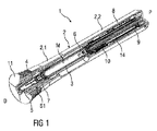
図1は、自動注射器1の例示的な実施形態の斜視図である。自動注射器1は、スリーブ形状の前方ケース2.1および後方ケース2.2を含む、ケース2を含む。キャップ11はケース2の遠位端に取り付けられている。ケース2内にスリーブ形状のニードルシュラウド7が嵌め込まれている。ケース2は、シリンジ3などの薬剤容器3、たとえばガラスシリンジを受容するように適用されている。薬剤容器3は、本明細書では「シリンジ3」と呼ばれる。シリンジ3は、薬剤Mを収容しておりかつシリンジ3の遠位端に針4が配置されている、充填済みシリンジであってよい。別の例示的な実施形態では、薬剤容器3は、薬剤Mを含み、取り外し可能な針に(たとえば、ねじ山、スナップ、摩擦、等によって)係合する、カートリッジであってよい。自動注射器1またはシリンジ3を組み立てるとき、針4には保護ニードルシース5が取り付けられている。シリンジ3を近位において封止するために、およびシリンジ3内に収容された液体薬剤Mを中空の針4を通して変位させるために、ストッパ6が配置されている。シリンジ3はケース2内に保持され、その中でその近位端において支持されている。
FIG. 1 is a perspective view of an exemplary embodiment of the
保護ニードルシース5は、キャップ11が取り外されるときに保護ニードルシース5も針4から取り外されるように、キャップ11に結合することができる。キャップ11は、キャップ11の取り外しを容易にするためのグリップ機能11.5を含んでよい。
The protective needle sheath 5 can be coupled to the
スリーブ形状のニードルシュラウド7は、ケース2の遠位端内に嵌め込まれている。制御ばね8は、ニードルシュラウド7をケース2に対して遠位方向Dに付勢するように配置されている。
The sleeve-shaped
ケース2の近位部分内に、圧縮ばねの形状の駆動ばね9が配置されている。プランジャ10が、駆動ばね9の力をストッパ6に送る役割を果たす。例示的な実施形態では、プランジャ10は中空であり、駆動ばね9はプランジャ10内に配置されて、後方ケース2.2に対してプランジャ10を遠位方向Dに付勢している。
A drive spring 9 in the shape of a compression spring is arranged in the proximal portion of the
自動注射器1は2つのサブアセンブリ、制御サブアセンブリ1.1および駆動サブアセンブリ1.2へと分割されてよい。このことにより、サブアセンブリ1.1、1.2の製造およびシリンジ3との最終的な組み付けの時間および場所に関して、柔軟性を改善することが可能になる。
The
図2は、制御サブアセンブリ1.1の斜視図である。図3は、制御サブアセンブリ1.1の分解斜視図である。制御サブアセンブリ1.1は、針4への到達および使用者が自動注射器1を使用するときに感じることになる力を制御する、あらゆる部材および機構を含む。制御サブアセンブリ1.1は、キャップ11と、ニードルシュラウド7と、前方ケース2.1と、を含む。例示的な実施形態では、制御機構1.1は、シリンジ3を保持するためのスリーブ形状のキャリア18を追加的に含んでよい。他の実施形態では、シリンジ3は、前方ケース2.1内に直接受容されてよい。
FIG. 2 is a perspective view of the control subassembly 1.1. FIG. 3 is an exploded perspective view of the control subassembly 1.1. The control subassembly 1.1 includes any member and mechanism that controls the force reaching the needle 4 and the force the user will feel when using the
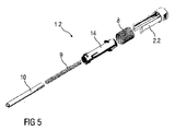
図4は、駆動サブアセンブリ1.2の斜視図である。図5は、駆動サブアセンブリ1.2の分解斜視図である。駆動サブアセンブリ1.2は、薬剤Mを送達するのに必要な構成要素を含む。シリンジ3内の薬剤Mの粘度または体積が変わる場合、駆動サブアセンブリ1.2の部材だけを変えればよい。駆動サブアセンブリ1.2は、プランジャ10と、駆動ばね9と、後方ケース2.2と、制御ばね8と、スリーブ形状のカラー14と、を含んでおり、これらについては以下で詳細に説明する。
FIG. 4 is a perspective view of the drive subassembly 1.2. FIG. 5 is an exploded perspective view of the drive subassembly 1.2. The driving subassembly 1.2 includes the components necessary to deliver the drug M. If the viscosity or volume of the drug M in the
図6は、組み立て中の自動注射器1の概略分解図である。自動注射器1を組み立てるために、取り付けられた針4および保護ニードルシース5を有するシリンジ3が、遠位方向Dに制御サブアセンブリ1.1内へと挿入される。その後、駆動サブアセンブリ1.2は、遠位方向Dに制御サブアセンブリ1.1内へと挿入される。
FIG. 6 is a schematic exploded view of the
図7は、プランジャ解放機構12を示している、自動注射器1の半透明の概略詳細側面図である。プランジャ解放機構12は、ニードルシュラウド7の押し下げ前にはプランジャ10の解放を防止するように、およびニードルシュラウド7が十分に押し下げられればプランジャ10を解放するように、配置されている。
FIG. 7 is a semi-transparent schematic detailed side view of the
プランジャ解放機構12は、シリンジの中身の放出の自動化された起動を制御するように適用されている。プランジャ解放機構12は、針が完全に挿入される直前に起動される。プランジャ解放機構12は、プランジャ10と、後方ケース2.2と、カラー14と、ニードルシュラウド7と、を含む。ニードルシュラウド7は、カラー14に動作可能に結合されており、かつカラー14を近位方向Pに押すように適用されている。
The
ニードルシュラウド7、後方ケース2.2、およびカラー14は、軸方向、すなわち遠位方向Dおよび近位方向Pにのみ移動するように構成されており、一方、プランジャ10は、回転方向で回転方向R1、R2にも、軸方向で遠位方向Dおよび近位方向Pにも移動できる。例示的な実施形態では、プランジャ解放機構12にはコンプライアント部材が存在しなくてよい、すなわち、部材は、すべて剛性で、部材内での相対変形なく全体として移動してもよい。プランジャ解放機構12は、図8Aから図8Eにおいて、5つの異なる状態で概略的に示されている。
The
図8Aは、組み立て前の状態のプランジャ解放機構12を示しており、プランジャ10は近位位置P1にある。組み立て前の状態では、カラー14における屋根形状のカム表面14.1、たとえば押出成形された経路上に、プランジャ10上のボス10.1が置かれている。これにより、たとえば駆動ばね9によって遠位方向Dへの力がプランジャ10に加えられるとき、プランジャ10が遠位方向Dに移動することが防止される。カム表面14.1は、プランジャ10を第1の回転方向R1へと回転させ、かつカラー14を反対の第2の回転方向R2へと僅かに回転させる、小さなトルクを誘起するように傾斜している。第1の回転方向R1へのプランジャ10の回転は、プランジャボス10.1が後方ケース2.2の長手方向のスロット2.3内に係合されることによって停止される。スロット2.3はプランジャボス10.1よりも僅かに広く、プランジャボス10.1およびプランジャ10の限定的な回転運動を可能にする。
FIG. 8A shows the
図8Bは、制御サブアセンブリ1.1内への駆動サブアセンブリ1.2の挿入中の状態の、プランジャ解放機構12を示している。ニードルシュラウド7上のシュラウドボス7.3は、カラー14上の第1のカラーリブ14.2と接触する。シュラウドボス7.3および第1のカラーリブ14.2は、ニードルシュラウド7の近位方向への動きによりカラー14が第1の回転方向R1に僅かに回転するように設計されている。このことにより、プランジャボス10.1は、カム表面14.1の先端部上に不安定な姿勢でセットされる。示された実施形態では、第1のカラーリブ14.2はこれを実現するように傾斜している。他の実施形態では、第1のカラーリブ14.2の代わりにシュラウドボス7.3が傾斜していてよい。同様に、第1のカラーリブ14.2およびシュラウドボス7.3の両方が傾斜していてよい。
FIG. 8B shows the
図8Cは、制御サブアセンブリ1.1内に駆動サブアセンブリ1.2をさらに挿入している状態の、プランジャ解放機構12を示している。その不安定な姿勢に起因して、第2の回転方向R2へのプランジャ10の回転の動きは、ボス10.1が中で案内される後方ケース2.2のスロット2.3の幅に起因して、ほとんど間を置かずに開始され停止する。カラー14は、ニードルシュラウド7の作用下で第1の回転方向R1に回転し続ける。加えて、駆動ばね9によって駆動されるプランジャ10もこの時点で、プランジャボス10.1がカラー14上のカム表面14.1に沿って降下し始めるにつれて、カラー14の回転を促進する。
FIG. 8C shows the
図8Dは、使用前の状態のプランジャ解放機構12を示している。第1の回転方向R1へのカラー14の回転の動きは、シュラウドボス7.3が第1のカラーリブ14.2に沿ったその進行を終え、L字形状の第2のカラーリブ14.3の第1の長手方向表面14.11に側方で当接するときに停止される。プランジャボス10.1は依然としてカラー14のカム表面14.1上にあるので、プランジャ10の解放が防止される。シュラウドボス7.3は、L字形状の第2のカラーリブ14.3の横断方向表面14.12の近位側の背後で係合して、カラー14に対するニードルシュラウド7の続く遠位方向Dへの運動を防止する。
FIG. 8D shows the
プランジャ解放機構12は、その使用前の構成である。
The
図8Eは、注射の始まりの状態のプランジャ解放機構12を示している。ニードルシュラウド7は、たとえば使用者がニードルシュラウド7を注射部位に押し付けることによって、近位方向Pに前方ケース2.1内へと移動され、これにより針4が注射部位内に挿入される。この動きの間、シュラウドボス7.3は、L字形状の第2のカラーリブ14.3の第1の長手方向表面14.11に沿って、近位方向Pに移動する。針の全挿入深さに達すると、シュラウドボス7.3は、第2のカラーリブ14.3の第1の長手方向表面14.11の近位端を越えて移動する。プランジャボス10.1は、駆動ばね9によって遠位方向Dに付勢されカム表面14.1に対して作用し、この結果、プランジャボス10.1がカム表面14.1の端部に達するまで、カラー14を第1の回転方向R1に回転させ、プランジャ10がトルクをそれ以上受けることなく遠位方向Dに移動することを可能にする。駆動ばね9の作用下で、プランジャ10はストッパ6を押し、シリンジ3の内容物の放出を開始する。
FIG. 8E shows the
図9Aは、第1のシュラウドロック機構15の概略図である。第1のシュラウドロック機構15は、キャップ11が所定位置にあるときニードルシュラウド7の押し下げを防止するように配置されており、この結果、落下時に自動注射器1が意図せず作動することが回避される。第1のシュラウドロック機構15は、キャップ11上の1つ、2つ、またはそれ以上のコンプライアントビーム11.3と、コンプライアントビーム11.3が中に係合できる、ニードルシュラウド7の対応する数のアパーチャ7.6と、を含む。コンプライアントビーム11.3および/またはアパーチャ7.6は、ニードルシュラウド7に対するキャップ11の遠位方向Dへの運動時に、コンプライアントビーム11.3を半径方向外向きに偏向させてアパーチャ7.6から外に出すように、傾斜がついている。シュラウド7に係合されたキャップ11のケース2に対する軸方向位置に応じて、ケース2上の半径方向止め具2.15は、コンプライアントビーム11.3の半径方向外向きの偏向を防止するかまたは可能にし、この結果、ニードルシュラウド7がキャップ11から係合解除するのを防止し、かつケース2に対するニードルシュラウド7の近位方向Pへの押し下げを制約する。ケース2に対するキャップ11の近位方向Pへの軸方向運動は、ケース2に当接するキャップ11上のリブによって限定され得る。
FIG. 9A is a schematic view of the first
図9Aは、制御サブアセンブリ1.1の組み立て後の第1のシュラウドロック機構15の概略図である。キャップ11上のコンプライアントビーム11.3は、ニードルシュラウド7内のアパーチャ7.6内に係合されている。半径方向止め具2.15は、コンプライアントビーム11.3から軸方向に離間されている。図9Bは、保護ニードルシース5をキャップ11に係合するための制御サブアセンブリ1.1内へのシリンジ3の挿入中の、第1のシュラウドロック機構15の概略図である。アパーチャ7.6は、キャップ11に対するニードルシュラウド7の遠位方向Dへの運動を可能にする、ある程度の隙間を提供する。前方ケース2.1もキャップ11に対して遠位方向Dに移動されて、半径方向止め具2.15をコンプライアントビーム11.3と軸方向に位置合わせし、キャップ11がニードルシュラウド7から係合解除するのを防止する。図9Cは第1のシュラウドロック機構15の概略図であり、シリンジ3の挿入後ニードルシュラウド7は、たとえば組み立て冶具(図示せず)によって、前方ケース2.1に対してさらに近位方向Pへと移動される。この状態で、駆動サブアセンブリ1.2を制御サブアセンブリ1.1に組み付けることができる。コンプライアントビーム11.3はアパーチャ7.6内に係合されたままであり、半径方向止め具2.15により、これらが係合解除することが防止される。
FIG. 9A is a schematic view of the first
制御サブアセンブリ1.1への駆動サブアセンブリ1.2の組み付け後、組み立て冶具は取り外されて、前方ケース2.1に対してニードルシュラウド7が遠位方向Dに戻って、図9Bに示した状態に再び到達することが可能になる。自動注射器1がこの状態で意図せず落下した場合、ニードルシュラウド7は、ニードルシュラウド7のアパーチャ7.6の遠位端が図9Cに示すようにコンプライアントビーム11.3に接触するまで、慣性力下でケース2に対して近位方向Pに移動できる。半径方向止め具2.15によって、およびキャップ11上のリブ11.4が前方ケース2.1に軸方向に当接することに起因して、コンプライアントビーム11.3がアパーチャ7.6から係合解除することが防止されるので、ニードルシュラウド7はそれ以上近位方向Pへは移動できず、これにより、自動注射器1を意図せずトリガすることが回避される。
After assembling the drive subassembly 1.2 to the control subassembly 1.1, the assembly jig was removed and the
図9Dは、コンプライアントビーム11.3が傾斜の作用により偏向してアパーチャ7.6から外に出ている状態の、キャップ11の取り外し中の第1のシュラウドロック機構15の概略図である。
FIG. 9D is a schematic view of the first
フィードバック機構13は、薬剤送達の完了を示す可聴および/または触覚フィードバックの提供を可能にするように配置されている。フィードバック機構13は、図10Aから図10Cにおいて、6つの異なる状態で概略的に示されている。
The
フィードバック機構13は、プランジャ10と、後方ケース2.2と、ニードルシュラウド7と、カラー14と、制御ばね8と、を含む。
The
図10Aは、使用前の状態のフィードバック機構13を示している。制御ばね8は、カラー14上の2つの第3のカラーリブ14.4とニードルシュラウド7との間で圧縮されている。プランジャ10はカラー14内で、カラー14上の接合部14.6の内側突起14.5間に配置されている。この結果、接合部14.6は内向きに偏向できない。接合部14.6は、後方ケース2.2の遠位アーム2.9に近位側で当接する。このことにより、カラー14の近位方向Pへの軸方向運動が防止される。接合部14.6はスナップ嵌め接合部であってよい。
FIG. 10A shows the
図10Bは、薬剤投薬の終わり近くでフィードバックがトリガされる状態のフィードバック機構13を示している。ストッパ6がシリンジ3内でほぼ底に達していてその移動の終わりに近づきつつあるプランジャ10は、摺動して内側突起14.5を越えて、スナップ嵌め接合部14.6の内向きの偏向を可能にする。ここまで半径方向外向きに偏向されていたスナップ嵌め接合部14.6は、内向きにその弛緩した形状へと戻り始め、後方ケース2.2上の遠位アーム2.9との接触を次第に失い、この結果、カラー14が制御ばね8の力の下で近位方向Pに移動することが可能になる。一方で、ニードルシュラウド7は、先行するステップにおいて針4が挿入されたときに近位方向Pへと押されており、この結果、制御ばね8をなお一層圧縮している。
FIG. 10B shows the
図10Cは、フィードバックを生成した後の投与の終わりにおける状態のフィードバック機構13を示している。プランジャ10は、シリンジ3のバレル内でのその行程を終えている。このようになる直前に、カラー14上に存在する2つのスナップ嵌め接合部14.6は、内向きに完全に引き込まれた状態になっており、後方ケース2.2上の遠位アーム2.9からデカップリングしている。カラー14はこの結果、制御ばね8の作用下で近位方向Pに推進された。カラー14は後方ケース2.2に当たり、これにより、投与が完了していることを示す可聴および/または触覚フィードバック、たとえばクリック音が生じた。
FIG. 10C shows the
例示的な実施形態では、フィードバックは、投与が実際に終わる前にトリガされる。 In an exemplary embodiment, the feedback is triggered before the actual end of administration.
図11Aは、第2のシュラウドロック機構16の概略図である。第2のシュラウドロック機構16は、自動注射器1を使用後に注射部位から取り外し、この結果、ケース2に対してニードルシュラウド7が遠位位置S1、たとえば第2の伸長位置へと遠位方向Dに並進運動した後で、ニードルシュラウド7をロックするように配置されている。第2のシュラウドロック機構16は、ニードルシュラウド7上の少なくとも1つの半径方向外向きに付勢されたコンプライアントシュラウドビーム7.4を含み、これは前方ケース2.1上の止め具2.12に近位側で当接するように適用されており、前方ケース2.1に対するニードルシュラウド7の近位方向Pへのさらなる運動を防止する。キャップ11は、ニードルシュラウド7上に嵌め込まれたときコンプライアントシュラウドビーム7.4を半径方向内向きに偏向させるように適用されており、ニードルシュラウド7が前方ケース2.1に対してさらに近位方向Pへと移動できるように、シュラウドビーム7.4が止め具2.12を近位方向Pに通過することを可能にする。
FIG. 11A is a schematic view of the second
図11Bは、制御サブアセンブリ1.1の組み立て後の第2のシュラウドロック機構16の概略図である。ニードルシュラウド7はキャップ11内に部分的に挿入されている。シュラウドビーム7.4は弛緩されており、前方ケース2.1の止め具2.12に近位側で当接している。これにより、ニードルシュラウド7が前方ケース2.1に対してさらに近位方向Pへと移動することが防止され、また制御サブアセンブリ1.1が1つにロックされた状態に維持される。
FIG. 11B is a schematic view of the second
図11Cは、制御サブアセンブリ1.1内へのシリンジ3の挿入中の第2のシュラウドロック機構16の概略図であり、ニードルシュラウド7は遠位方向Dにキャップ11内へとさらに移動されており、この結果キャップ11は、シュラウドビーム7.4を内向きに偏向させ、止め具2.12とのその当接を解消させる。ニードルシュラウド7はこの結果、前方ケース2.1に対して近位方向Pに自由に移動できる。
FIG. 11C is a schematic view of the second
図11Dは、制御サブアセンブリ1.1への駆動サブアセンブリ1.2の最終組み付け後の第2のシュラウドロック機構16の概略図である。ニードルシュラウド7は、たとえば組み立て冶具(図示せず)によって、前方ケース2.1に対して近位方向Pへとさらに移動されている。この状態で、駆動サブアセンブリ1.2を制御サブアセンブリ1.1に組み付けることができる。その後、組み立て冶具は取り外され、ニードルシュラウド7は、シュラウドばね8の負荷の下で前方ケース2.1に対して遠位方向Dに戻ることが可能になる。ただしこの運動は、プランジャ解放機構12によって限定される。ニードルシュラウド7はしたがって図11Dの位置にあり、このときシュラウドビーム7.4は、シュラウドビーム7.4の偏向を防止する前方ケース2.1の止め具2.12によって、半径方向外向きに支持されている。
FIG. 11D is a schematic view of the second
図11Eは、ニードルシュラウド7を遠位位置S1にロックした、第2のシュラウドロック機構16の概略図である。ニードルシュラウド7が引き込まれた位置RPから遠位位置S1に向かって移動している際、シュラウドビーム7.4は止め具2.12を遠位方向Dに通過し、半径方向外向きに弛緩するが、これはキャップ11がもはや存在しないために可能となる。これ以降、シュラウドビーム7.4は、止め具2.12に当たることになるので、近位方向Pに戻ることができない。ニードルシュラウド7はこの結果、遠位位置S1にロックされる。ケース2上のケースボスがニードルシュラウド7のシュラウドボス(図示せず)と係合することによって、ニードルシュラウド7のさらなる伸長が防止され得る。
FIG. 11E is a schematic view of the second
図12Aは、第2のシュラウドロック機構の機能が統合されている、プランジャ解放機構120の別の例示的な実施形態の概略図である。プランジャ解放機構120は、プランジャ10と、後方ケース2.2と、ニードルシュラウド7と、カラー14と、を含む。
FIG. 12A is a schematic representation of another exemplary embodiment of the
ニードルシュラウド7およびプランジャ10は、軸方向、すなわち遠位方向Dおよび近位方向Pにのみ移動するように構成されており、一方、カラー14は、回転方向で回転方向R1、R2に、および軸方向で近位方向Pにのみ、移動できる。後方ケース2.2は固定されている。例示的な実施形態では、プランジャ解放機構120にはコンプライアント部材が存在しなくてよい、すなわち、部材は、すべて剛性で、部材内での相対変形なく全体として移動してもよい。
The
図12Aは、組み立て前の状態のプランジャ解放機構120を示しており、プランジャ10は近位位置P1にある。組み立て前の状態では、カラー14におけるカム表面14.1、たとえば押出成形された経路上に、プランジャ10上のボス10.1が置かれている。これにより、たとえば駆動ばね9によって遠位方向Dへの力がプランジャ10に加えられるとき、プランジャ10が遠位方向Dに移動することが防止される。カム表面14.1は、間に先端部を画成している2つの傾斜している斜面を含む。ボス10.1が上に置かれるカム表面14.1の斜面の角度により、プランジャ10を第2の回転方向R2へと回転させ、かつカラー14を反対の第1の回転方向R1へと僅かに回転させる、小さなトルクが誘起される。第1の回転方向R1へのプランジャ10の回転は、プランジャボス10.1が後方ケース2.2の長手方向のスロット2.3内に係合されることによって停止される。第1の回転方向R1へのカラー14の回転は、カラー14上の接触面14.10が後方ケース2.2上のケースリブ2.10に係合することによって停止される。接触面14.10は、ケースリブ2.10に動作可能に当接して後方ケース2.2に対するカラー14の限定的な回転を可能にするように適用された、2つの側面14.14、14.15を含む。さらに、接触面14.10は、ケースリブ2.10に当接してカラー14の遠位方向Dへの運動を防止するように適用された、遠位表面14.16を含む。プランジャ10を遠位方向Dに付勢する駆動ばね9からの軸方向の負荷は、プランジャボス10.1およびカム表面14.1を通してプランジャ10からカラー14に、ならびにさらに、接触面14.10およびケースリブ2.10を通してカラー14から後方ケース2.2に結合される。制御ばね8は、カラー14とニードルシュラウド7との間に配置されており、この結果、カラー14が近位方向Pに付勢される。駆動ばね9の負荷は制御ばね8の負荷よりもはるかに大きいので、カラー14は後方ケース2.2に対して図12Aの位置に保持される。
FIG. 12A shows the
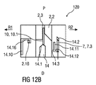
図12Bは、制御サブアセンブリ1.1内への駆動サブアセンブリ1.2の挿入中の状態の、プランジャ解放機構12を示している。シュラウド7上のシュラウドボス7.3は、カラー14上の第1のカラーリブ14.2と接触する。シュラウドボス7.3および第1のカラーリブ14.2は、シュラウド7の近位方向への動きによりカラー14が第2の回転方向R2に僅かに回転するように設計されている。このことにより、プランジャボス10.1は、カム表面14.1の先端部上に不安定な姿勢でセットされる。示された実施形態では、第1のカラーリブ14.2はこれを実現するように傾斜している。他の実施形態では、第1のカラーリブ14.2の代わりにシュラウドボス7.3が傾斜していてよい。同様に、第1のカラーリブ14.2およびシュラウドボス7.3の両方が傾斜していてよい。カラー14の回転が続くにつれ、プランジャボス10.1との接触面となるカム表面14.1は、カラー14に適用されるトルクの方向を反転させる反対の角度へと移行する。カラー14の回転はしたがって、ニードルシュラウド7によって力を適用されることなく続く。
FIG. 12B shows the
図12Cは、使用前の状態のプランジャ解放機構12を示している。カラー14は、ニードルシュラウド7の作用下で第2の回転方向R2に回転し続ける。加えて、駆動ばね9によって駆動されるプランジャ10もこの時点で、プランジャボス10.1がカラー14上のカム表面14.1に沿って降下し始めるにつれて、カラー14の回転を促進する。第2の回転方向R2へのカラー14の回転の動きは、シュラウドボス7.3が、L字形状の第2のカラーリブ14.3の第1の長手方向表面14.11に側方で当接するときに停止される。プランジャボス10.1は依然としてカラー14のカム表面14.1上にあるので、プランジャ10の解放が防止される。シュラウドボス7.3は、L字形状の第2のカラーリブ14.3の横断方向表面14.12の近位側の背後で係合して、カラー14に対するニードルシュラウド7の続く遠位方向Dへの運動を防止する。
FIG. 12C shows the
プランジャ解放機構120は、その使用前の構成である。
The
図12Dは、ニードルシュラウド7の押し下げ中の状態のプランジャ解放機構120を示している。ニードルシュラウド7は、たとえば使用者がニードルシュラウド7を注射部位に押し付けることによって、近位方向Pに前方ケース2.1内へと移動され、これにより針4が注射部位内に挿入される。この動きの間、シュラウドボス7.3は、L字形状の第2のカラーリブ14.3の第1の長手方向表面14.11に沿って、近位方向Pに移動する。針の全挿入深さに達すると、シュラウドボス7.3は、第2のカラーリブ14.3の第1の長手方向表面14.11の近位端を越えて移動する。駆動ばね9によって遠位方向Dに付勢されカム表面14.1に対して作用するプランジャボス10.1は、この結果、カラー14を第2の回転方向R2にさらに回転させる。
FIG. 12D shows the
図12Eは、プランジャ10の解放中の状態のプランジャ解放機構120を示している。カラー14は、プランジャボス10.1がカム表面14.1の端部に達するまで回転を続けており、プランジャ10がトルクをそれ以上受けることなく遠位方向Dに移動する。カラー14は、カム表面14.1に対して作用するプランジャボス10.1を通して駆動ばね9によって遠位方向Dにもはや付勢されていないので、カラー14はこの時点で、制御ばね8の力の作用下でニードルシュラウド7に対して近位方向Pに自由に移動できる。この移動は、図10Aに示すように、フィードバック機構13によって限定される。ニードルシュラウド7が回転的に固定されたままである間にカラー14が回転されたので、これまで第2の回転方向R2を向いているL字形状の第2のカラーリブ14.3の第1の長手方向表面14.11と位置合わせされていたシュラウドボス7.3はこの時点で、第1の回転方向R1を向いているL字形状の第2のカラーリブ14.3の反対側の第2の長手方向表面14.13と位置合わせされている。
FIG. 12E shows the
図12Fは、薬物送達中の状態のプランジャ解放機構120を示している。駆動ばね9の作用下で、プランジャ10はストッパ6を押し、シリンジ3の内容物の放出を開始する。
FIG. 12F shows the
図12Gは、注射ストロークの終わり近くにおけるプランジャ解放機構120の概略図である。フィードバック機構13は、図10Bに示すように、カラー14を解放し、これが制御ばね8の作用下で近位方向Pに移動することを可能にする。カラー14、たとえばカム表面14.1は、後方ケース2.2上の傾斜表面2.11に当接している。この接触により、投与がほぼ完了していることを示す、可聴およびまたは触覚フィードバックが生じる。後方ケース2.2上の傾斜表面2.11は、カラー14に対して第1の回転方向R1にトルクを付与する。ニードルシュラウド7がその軸方向位置に留まっている間にカラー14が近位方向Pに移動されたので、シュラウドボス7.3は、第1の回転方向R1を向いているL字形状の第2のカラーリブ14.3の第2の長手方向表面14.13に当接している。カラー14に対するトルクはこの結果、シュラウドボス7.3と第2のカラーリブ14.3との間の接触によって分解される。
FIG. 12G is a schematic view of the
図12Hは、ニードルシュラウド7の伸長中の注射ストローク後のプランジャ解放機構120の概略図である。自動注射器1が注射部位から取り外されるとき、ニードルシュラウド7は、制御ばね8の作用下で遠位方向Dに延びている。この動きは、シュラウドボス7.3がもはや第2のカラーリブ14.3を支持しなくなるまで続く。この時点で、ニードルシュラウド7は完全に延びている。
FIG. 12H is a schematic view of the
図12Jは、延びたニードルシュラウド7をロックアウトした使用後の状態のプランジャ解放機構120の概略図である。シュラウドボス7.3は第2のカラーリブ14.3をもはや支持していないので、傾斜表面2.11上のカム表面14.1の係合を通してカラー14に適用されるトルクにより、カラー14が第1の回転方向R1に回転する。この回転は、カム表面14.1が、さらなる回転を防止する後方ケース2.2の角度止め具2.13と接触するまで続く。この位置では、第2のカラーリブ14.3は、シュラウドボス7.3の軸方向経路内で位置合わせされている。したがって、ニードルシュラウド7を近位方向Pに再び押そうとする場合、この移動はカラー14によって阻止される。これにより、ニードルシュラウド7のさらなる押し下げおよび針4の再露出を防止する、シュラウドロックがもたらされる。
FIG. 12J is a schematic view of the
自動注射器1の操作の流れは以下の通りである。
The operation flow of the
自動注射器1は最初は、図1に示すような状態である。プランジャ解放機構12は、図8Dに示すような使用前の状態である。フィードバック機構13は、図8Bに示すような使用前の状態である。第1のシュラウドロック機構15は、図10Aに示すような使用前の状態である。代替のプランジャ解放機構120を適用する場合、これは図12Cの使用前の状態である。
Initially, the
使用者はキャップ11を取り外し、これを遠位方向Dに引いてケース2から離す。保護ニードルシース5は、キャップ11が取り外されるときに保護ニードルシース5も針4から取り外されるように、キャップ11に結合することができる。図13は、キャップ11を取り外した状態の自動注射器1の長手方向斜視断面図である。ニードルシュラウド7は遠位位置S1にある。
The user removes the
図14は、ニードルシュラウド7が、たとえばこれを注射部位に押し当ててケース2を前方に摺動させることによって、近位方向Pに移動された状態の、自動注射器1の長手方向斜視断面図である。制御ばね8はカラー14とニードルシュラウド7との間に保持されており、ケース2がニードルシュラウド7に対して前方に移動されるとき、さらに圧縮される。ニードルシュラウド7を除いて、自動注射器1のすべての構成要素は、ケース2とともに移動する。ニードルシュラウド7は、自動注射器1の残りの部材とは対照的に近位方向Pに移動し、この結果、プランジャ解放機構12または120を始動させる。プランジャ解放機構12はこの結果、図8Eに示すような状態に到達する。代替のプランジャ解放機構120が適用される場合、これは図12Dに示すような状態に到達する。
FIG. 14 is a longitudinal perspective sectional view of the
図15は、ニードルシュラウド7が近位方向Pに近位位置S2へと完全に移動されて、針4が注射部位において挿入深さに達している状態の、自動注射器1の長手方向斜視断面図である。ニードルシュラウド7が完全に押し下げられると、プランジャ10が図8Eに示すように解放され、薬剤送達が開始される。駆動ばね9が伸長を開始し、プランジャ10を遠位方向Dに押して薬剤Mを注射させる。代替のプランジャ解放機構120が適用される場合、プランジャ10は図12Eに示すように解放される。
FIG. 15 is a longitudinal perspective sectional view of the
図16は、フィードバック機構13の解放後に薬剤Mを送達中の自動注射器1の長手方向斜視断面図である。プランジャ10がシリンジ3のバレルを移動していくのに伴って薬剤Mの送達が進行する際、フィードバック機構13が起動される。フィードバック機構13は、図10Bに示すような状態に到達する。
FIG. 16 is a longitudinal perspective sectional view of the
図17は、可聴フィードバックの生成前の投与の終わりにおける自動注射器1の長手方向斜視断面図である。フィードバック機構13は、図10Cに示すような状態に到達する。プランジャ10はシリンジ3のバレル内でストッパ6を完全に前進させ、遠位位置P2に到達する。注射が完了し、フィードバック機構13が動作する際にカラー14が後方ケース2.2に当たることを通して、可聴および/または触覚フィードバックが提供される。
FIG. 17 is a longitudinal perspective sectional view of the
自動注射器1が移動して注射部位から離れる場合、ニードルシュラウド7は、制御ばね8によって駆動されて遠位方向Dに前進する。ニードルシュラウド7はその使用前の位置に戻る。第2のシュラウドロック16は図11Eに示すような状態に到達して、ニードルシュラウド7をその軸方向位置にロックする。固有のシュラウドロックを有する代替のプランジャ解放機構120が適用される場合、これは図12Hの状態を通って移行し、図12Jに示すような状態に到達する。
When the
図18は、キャップ11を含むニードルシース取り外し機構17を有する自動注射器1の遠位端の長手方向断面図である。ニードルシース取り外し機構17は、上記した自動注射器1において適用されてよい。
FIG. 18 is a longitudinal sectional view of the distal end of the
例示的な実施形態では、キャップ11は、ケース2の遠位端に取り外し可能に配設されていてよい。キャップ11は、ケース2に係合するように配置された要素(たとえば、バーブ、フック、狭窄セクション、等)、ケース2内に嵌め込まれたニードルシュラウド7、および/または針4上の保護ニードルシース5を含んでよい。保護ニードルシース5は、ゴム製および/またはプラスチック製であってよい。例示的な実施形態では、保護ニードルシース5は、針4に係合するように適用されたゴム製内面とゴム製内面の外側部分を少なくとも部分的に覆うプラスチック製外面とから形成された、剛性ニードルシールド(RNS)である。キャップ11は、キャップ11を(たとえば、キャップ11をケース2に対してねじり、かつ/または引っ張ることによって)取り外しやすくするためのグリップ機能11.5を含んでよい。例示的な実施形態では、グリップ機能11.5は、1つまたはそれ以上のリブ、リッジ、突起部、バンプ、切欠き、テクスチャ加工面、またはオーバーモールドされたコーティング(ゴム、弾性体、等)等を含んでよい。
In an exemplary embodiment, the
例示的な実施形態では、自動注射器1からキャップ11を取り外すときに保護ニードルシース5を薬剤容器3から取り外すための、シース取り外し機構17が配置されている。シース取り外し機構17は、保護ニードルシース5に係合するように適用された、キャップ11上の1つまたはそれ以上のコンプライアントシース取り外しビーム11.7を含んでよい。典型的には、シース取り外しビーム11.7は、キャップ11の遠位面11.10から近位方向Pに延びているか、または、キャップ11の遠位面11.10から近位方向Pに延びている内部スリーブの一部である。コンプライアントシース取り外しビーム11.7は、内向きのレッジ11.8をそれぞれ含む。コンプライアントシース取り外しビーム11.7が弛緩しているとき、レッジ11.8は、これらの間に保護ニードルシース5の直径よりも小さい隙間を提供する。例示的な実施形態では、キャップ11の遠位面11.10の開口部11.11を通して、軸方向に組み立て器具を挿入できる。
In an exemplary embodiment, a
別の例示的な実施形態では、キャップ11の側方領域内に、組み立て器具の挿入を可能にするための1つまたはそれ以上の側方アパーチャ11.9が配置されている。対応する側方アパーチャが、キャップ11がケース2に取り付けられるときに側方アパーチャ11.9の組がそれぞれ位置合わせされるように、ケース2およびニードルシュラウド7に同様に配置されていてよい。
In another exemplary embodiment, one or more lateral apertures 11.9 are arranged within the lateral region of the
キャップ11は、ニードルシュラウド7に対して近位方向Pに移動されることによって、自動注射器1に組み付けられる。キャップ11が自動注射器1に取り付けられているとき、シース取り外しビーム11.7は、これを許容するのに十分な程度に広いニードルシュラウド7内に挿入される。
The
キャップ11が自動注射器1に取り付けられるとき、ケース2に対するキャップ11の近位方向Pへの軸方向運動は、ケース2に当接するキャップ11上のリブ11.4によって限定される。
When the
くさび形の組み立て器具を、シース取り外しビーム11.7のうちの2つの間に係合させてこれらを拡開させ、これによりこれらを半径方向外向きの方向に偏向させることができる。これにより、内向きのレッジ11.8によって画成される隙間が、保護ニードルシース5が通過できる程度まで広げられる。例示的な実施形態では、くさび形の組み立て器具は、第2のシュラウドロック機構16の係合とプランジャ解放機構12または120の準備(priming)とを可能にするのと同じ動きでシュラウド7を軸方向に変位させるために、配置することもできる。
A wedge-shaped assembly device can be engaged between two of the sheath removal beams 11.7 to widen them, thereby deflecting them in the radial outward direction. As a result, the gap defined by the inward ledge 11.8 is widened to the extent that the protective needle sheath 5 can pass through. In an exemplary embodiment, the wedge-shaped assembly device axes the
自動注射器1および/または薬剤容器3を組み立てるとき、針4に保護ニードルシース5を取り外し可能に結合してよい。保護ニードルシース5はゴム製のニードルシース、または(ゴムおよび全体的もしくは部分的なプラスチック製シェルから構成される)剛性のニードルシースであってよい。他の例示的な実施形態では、薬剤容器3は、薬剤Mを含み、取り外し可能な針に(たとえば、ねじ山、スナップ、摩擦、等によって)係合する、カートリッジであってよい。
When assembling the
薬剤容器3および保護ニードルシース5はケース2内に挿入され、遠位方向Dに押される。組み立て器具のおかげで、コンプライアントシース取り外しビーム11.7上のレッジ11.8の間の隙間は、保護ニードルシース5の挿入を許容する程度に十分に広い。例示的な実施形態では、ケース2は、たとえば薬剤容器3の首部分に係合することによって、ケース2内での薬剤容器3の遠位方向Dへの軸方向運動を限定する、軸方向止め具を含んでよい。同様に、首部分はキャリア18によって保持されてよく、またキャリア18は、ケース2内で異なる方法で保持されてよい。
The
次いで組み立て器具をキャップ11の遠位面11.10の開口部11.11から取り外すことができ、この結果、シース取り外しビーム11.7はもはや拡開していない状態になる。これらのビームの剛直性により、シース取り外しビーム11.7は半径方向内向きに弛緩し、内向きのレッジ11.8はこれらの間の隙間を小さくして保護ニードルシース5の近位端に係合し、この結果、キャップ11を保護ニードルシース5に軸方向に結合する。例示的な実施形態では、シース取り外しビーム11.7は、器具が取り外されたときこれらが保護ニードルシース5と常に密に接触していることを保証する、内向きに偏向した位置に成形されている。くさび形の組み立て器具は、シース取り外しビーム11.7が変形して塑性降伏するまでには至らないように設計することができる。保護ニードルシース5とシース取り外しビーム11.7との間の接点は、保護ニードルシース5が取り外される際にシース取り外しビーム11.7を開くように作用するモーメントを最小にするように配置されている。この結果、保護ニードルシース5のグリップは、シース取り外しビーム11.7によって及ぼされる半径方向の圧縮力には依拠せず、ケース2に対する遠位方向Dにおいてキャップ11に及ぼされる力に依拠する。例示的な実施形態では、くさび形の組み立て器具を、キャップの取り外し中にキャップ11に及ぼされる力の方向に対して垂直な方向に、シース取り外しビーム11.7を拡開するように配置できる。
The assembly device can then be removed from the opening 11.11 on the distal surface 11.10 of the
キャップ11がケース2に対して遠位方向Dに引かれるとき、保護ニードルシース5の近位端に係合されたレッジ11.8は、保護ニードルシース5を薬剤容器3から引き離す。キャップの取り外し後、保護ニードルシース5は、保護ニードルシース5がキャップ11から脱落するのを防止するために、レッジ11.8および2つの小さいリブ11.12によって保持することができる。
When the
例示的な実施形態では、ニードルシュラウド7を押圧するのに必要な力は、約2〜12Nであり得る。同様に、この機構はより大きい力で機能し得る。
In an exemplary embodiment, the force required to press the
ケース2は、使用者が、薬剤Mを明確に調べることと、薬剤送達の進行の推測を可能にするために前進中のプランジャ10を観察することと、使用者が使用済みの自動注射器1と未使用の自動注射器1とを見分けるのを助けることと、を可能にする、視認窓(図示せず)を含んでよい。
In
例示的な実施形態では、制御サブアセンブリ1.1が組み立てられるときに、キャップ11と前方ケース2.1との間に不正防止ストリップ(tamper strip)を配置してよい。
In an exemplary embodiment, a tamper strip may be placed between the
自動注射器1は、機構への有害な効果を何ら伴わずに、注射部位に複数回押し当てることができる。ニードルシュラウド7を押し下げるための力は、6N未満であってよい。
The
自動注射器1で使用されるシリンジ3は、たとえば1mlシリンジ3であってよい。
The
薬剤Mの送達が完了する前に針4を引き込むことができるので、自動注射器1は常に針に関して安全である。
The
プランジャ10のみが駆動ばね9の比較的高い力を受けるので、自動注射器1のその他の構成要素は影響を受けず、このため信頼性高まりまた保存可能期間が延びる。
Since only the
異なる粘度の薬物を送達するために、挿入機能または引き込み機能に影響を与えることなく駆動ばね9を交換できるので、自動注射器1はプラットフォームとして使用するのに適している。このことは高粘度の流体に関して特に有利である。
The
プランジャ解放機構12、120を、薬物送達デバイス1、たとえば自動注射器1において、記載したフィードバック機構13、第1のシュラウドロック機構15および第2のシュラウドロック機構16、ならびにニードルシース取り外し機構17を用いずに、またはこれらの機構のうちの1つもしくは複数の別の種類を用いて、適用することができる。
The
本明細書で使用する用語「薬物」または「薬剤」は、1つまたはそれ以上の薬学的に活性な化合物を説明するために本明細書において使用される。以下に説明されるように、薬物または薬剤は、1つまたはそれ以上の疾患を処置するための、さまざまなタイプの製剤の少なくとも1つの低分子もしくは高分子、またはその組み合わせを含むことができる。例示的な薬学的に活性な化合物は、低分子;ポリペプチド、ペプチド、およびタンパク質(たとえばホルモン、成長因子、抗体、抗体フラグメント、および酵素);炭水化物および多糖類;ならびに核酸、二本鎖または一本鎖DNA(裸およびcDNAを含む)、RNA、アンチセンスDNAおよびRNAなどのアンチセンス核酸、低分子干渉RNA(siRNA)、リボザイム、遺伝子、およびオリゴヌクレオチドを含むことができる。核酸は、ベクター、プラスミド、またはリポソームなどの分子送達システムに組み込むことができる。これらの薬物の1つまたはそれ以上の混合物もまた、企図される。 The term "drug" or "drug" as used herein is used herein to describe one or more pharmaceutically active compounds. As described below, a drug or drug can include at least one small molecule or macromolecule of various types of formulations, or a combination thereof, for treating one or more diseases. Exemplary pharmaceutically active compounds are small molecules; polypeptides, peptides, and proteins (eg, hormones, growth factors, antibodies, antibody fragments, and enzymes); carbohydrates and polysaccharides; and nucleic acids, double-stranded or single. It can include double-stranded DNA (including bare and cDNA), RNA, antisense nucleic acids such as antisense DNA and RNA, small interfering RNA (siRNA), ribozymes, genes, and oligonucleotides. Nucleic acids can be integrated into molecular delivery systems such as vectors, plasmids, or liposomes. Mixtures of one or more of these drugs are also contemplated.
用語「薬物送達デバイス」は、薬物をヒトまたは動物の体内に投薬するように構成されたあらゆるタイプのデバイスまたはシステムを包含するものである。限定されることなく、薬物送達デバイスは、注射デバイス(たとえばシリンジ、ペン型注射器、自動注射器、大容量デバイス、ポンプ、かん流システム、または眼内、皮下、筋肉内、もしくは血管内送達にあわせて構成された他のデバイス)、皮膚パッチ(たとえば、浸透圧性、化学的、マイクロニードル)、吸入器(たとえば鼻用または肺用)、埋め込み(たとえば、コーティングされたステント、カプセル)、または胃腸管用の供給システムとすることができる。ここに説明される薬物は、針、たとえば小ゲージ針を含む注射デバイスで特に有用であることができる。 The term "drug delivery device" includes any type of device or system configured to administer a drug into the human or animal body. Without limitation, drug delivery devices can be adapted to injection devices such as syringes, pen-type injectors, automatic injectors, high volume devices, pumps, perfusion systems, or intraocular, subcutaneous, intramuscular, or intravascular delivery. For other configured devices), skin patches (eg, osmotic, chemical, microneedles), inhalers (eg for nasal or lung), implants (eg for coated stents, capsules), or gastrointestinal tract It can be a supply system. The drugs described herein can be particularly useful in injection devices including needles, such as small gauge needles.
薬物または薬剤は、薬物送達デバイスで使用するように適用された主要パッケージまたは「薬物容器」内に含むことができる。薬物容器は、たとえば、カートリッジ、シリンジ、リザーバ、または1つまたはそれ以上の薬学的に活性な化合物の保存(たとえば短期または長期保存)に適したチャンバを提供するように構成された他の容器とすることができる。たとえば、一部の場合、チャンバは、少なくとも1日(たとえば1日から少なくとも30日まで)の間薬物を保存するように設計することができる。一部の場合、チャンバは、約1ヶ月から約2年の間薬物を保存するように設計することができる。保存は、室温(たとえば約20℃)または冷蔵温度(たとえば約−4℃から約4℃まで)で行うことができる。一部の場合、薬物容器は、薬物製剤の2つまたはそれ以上の成分(たとえば薬物および希釈剤、または2つの異なるタイプの薬物)を別々に、各チャンバに1つずつ保存するように構成された二重チャンバカートリッジとすることができ、またはこれを含むことができる。そのような場合、二重チャンバカートリッジの2つのチャンバは、ヒトまたは動物の体内に投薬する前、および/または投薬中に薬物または薬剤の2つまたはそれ以上の成分間で混合することを可能にするように構成することができる。たとえば、2つのチャンバは、これらが(たとえば2つのチャンバ間の導管によって)互いに流体連通し、所望の場合、投薬の前にユーザによって2つの成分を混合することを可能にするように構成することができる。代替的に、またはこれに加えて、2つのチャンバは、成分がヒトまたは動物の体内に投薬されているときに混合することを可能にするように構成することができる。 The drug or drug can be contained within a major package or "drug container" applied for use with the drug delivery device. Drug containers are, for example, with cartridges, syringes, reservoirs, or other containers configured to provide a chamber suitable for storage (eg, short-term or long-term storage) of one or more pharmaceutically active compounds. can do. For example, in some cases, the chamber can be designed to store the drug for at least one day (eg, from 1 to at least 30 days). In some cases, the chamber can be designed to store the drug for about 1 month to about 2 years. Storage can be performed at room temperature (eg, about 20 ° C.) or refrigeration temperature (eg, from about -4 ° C. to about 4 ° C.). In some cases, drug containers are configured to store two or more components of a drug formulation (eg, drugs and diluents, or two different types of drugs) separately, one in each chamber. Can be, or can include, a double chamber cartridge. In such cases, the two chambers of the dual chamber cartridge allow the drug or drug to be mixed between two or more components before and / or during dosing into the human or animal body. Can be configured to: For example, the two chambers are configured to allow them to fluidize with each other (eg, by a conduit between the two chambers) and, if desired, allow the user to mix the two components prior to dosing. Can be done. Alternatively, or in addition, the two chambers can be configured to allow the ingredients to be mixed when being administered into the human or animal body.
本明細書において説明される薬物送達デバイスおよび薬物は、数多くの異なるタイプの障害の処置および/または予防に使用することができる。例示的な障害は、たとえば、糖尿病、または糖尿病性網膜症などの糖尿病に伴う合併症、深部静脈血栓塞栓症または肺血栓塞栓症などの血栓塞栓症を含む。さらなる例示的な障害は、急性冠症候群(ACS)、狭心症、心筋梗塞、がん、黄斑変性症、炎症、枯草熱、アテローム性動脈硬化症および/または関節リウマチである。 The drug delivery devices and drugs described herein can be used to treat and / or prevent a number of different types of disorders. Exemplary disorders include, for example, diabetes, or diabetic complications such as diabetic retinopathy, and thromboembolism such as deep vein thromboembolism or pulmonary thromboembolism. Further exemplary disorders are acute coronary syndrome (ACS), angina, myocardial infarction, cancer, macular degeneration, inflammation, hay fever, atherosclerosis and / or rheumatoid arthritis.
糖尿病または糖尿病に伴う合併症の処置および/または予防のための例示的な薬物は、インスリン、たとえばヒトインスリン、またはヒトインスリン類似体もしくは誘導体、グルカゴン様ペプチド(GLP−1)、GLP−1類似体もしくはGLP−1受容体アゴニスト、またはその類似体もしくは誘導体、ジペプチジルペプチダーゼ−4(DPP4)阻害剤、または薬学的に許容される塩もしくはその溶媒和物、またはそれらの任意の混合物を含む。本明細書において使用される用語「誘導体」は、元の物質と構造的に十分同様のものであり、それによって同様の機能または活性(たとえば治療効果性)を有することができる任意の物質を指す。 Exemplary drugs for the treatment and / or prevention of diabetes or diabetes-related complications are insulin, such as human insulin, or human insulin analogs or derivatives, glucagon-like peptides (GLP-1), GLP-1 analogs. Alternatively, it comprises a GLP-1 receptor agonist, or analog or derivative thereof, a dipeptidyl peptidase-4 (DPP4) inhibitor, or a pharmaceutically acceptable salt or a solvent thereof, or any mixture thereof. As used herein, the term "derivative" refers to any substance that is structurally sufficiently similar to the original substance and thereby capable of having similar function or activity (eg, therapeutic efficacy). ..
例示的なインスリン類似体は、Gly(A21),Arg(B31),Arg(B32)ヒトインスリン(インスリングラルギン);Lys(B3),Glu(B29)ヒトインスリン;Lys(B28),Pro(B29)ヒトインスリン;Asp(B28)ヒトインスリン;B28位におけるプロリンがAsp、Lys、Leu、Val、またはAlaで置き換えられており、B29位において、LysがProで置き換えられていてもよいヒトインスリン;Ala(B26)ヒトインスリン;Des(B28−B30)ヒトインスリン;Des(B27)ヒトインスリンおよびDes(B30)ヒトインスリンである。 Illustrative insulin analogs are Gly (A21), Arg (B31), Arg (B32) human insulin (insulin glargine); Lys (B3), Glu (B29) human insulin; Lys (B28), Pro (B29). Human insulin; Asp (B28) Human insulin; Proline at position B28 is replaced with Asp, Lys, Leu, Val, or Ala, and Lys may be replaced with Pro at position B29 Human insulin; Ala ( B26) human insulin; Des (B28-B30) human insulin; Des (B27) human insulin and Des (B30) human insulin.
例示的なインスリン誘導体は、たとえば、B29−N−ミリストイル−des(B30)ヒトインスリン;B29−N−パルミトイル−des(B30)ヒトインスリン;B29−N−ミリストイルヒトインスリン;B29−N−パルミトイルヒトインスリン;B28−N−ミリストイルLysB28ProB29ヒトインスリン;B28−N−パルミトイル−LysB28ProB29ヒトインスリン;B30−N−ミリストイル−ThrB29LysB30ヒトインスリン;B30−N−パルミトイル−ThrB29LysB30ヒトインスリン;B29−N−(N−パルミトイル−γ−グルタミル)−des(B30)ヒトインスリン;B29−N−(N−リトコリル−γ−グルタミル)−des(B30)ヒトインスリン;B29−N−(ω−カルボキシヘプタデカノイル)−des(B30)ヒトインスリン、およびB29−N−(ω−カルボキシヘプタデカノイル)ヒトインスリンである。例示的なGLP−1、GLP−1類似体およびGLP−1受容体アゴニストは、たとえば:リキシセナチド(Lixisenatide)/AVE0010/ZP10/リキスミア(Lyxumia)、エキセナチド(Exenatide)/エクセンディン−4(Exendin−4)/バイエッタ(Byetta)/ビデュリオン(Bydureon)/ITCA650/AC−2993(アメリカドクトカゲの唾液腺によって産生される39アミノ酸ペプチド)、リラグルチド(Liraglutide)/ビクトザ(Victoza)、セマグルチド(Semaglutide)、タスポグルチド(Taspoglutide)、シンクリア(Syncria)/アルビグルチド(Albiglutide)、デュラグルチド(Dulaglutide)、rエクセンディン−4、CJC−1134−PC、PB−1023、TTP−054、ラングレナチド(Langlenatide)/HM−11260C、CM−3、GLP−1エリゲン、ORMD−0901、NN−9924、NN−9926、NN−9927、ノデキセン(Nodexen)、ビアドール(Viador)−GLP−1、CVX−096、ZYOG−1、ZYD−1、GSK−2374697、DA−3091、MAR−701、MAR709、ZP−2929、ZP−3022、TT−401、BHM−034、MOD−6030、CAM−2036、DA−15864、ARI−2651、ARI−2255、エキセナチド(Exenatide)−XTENおよびグルカゴン−Xtenである。 Exemplary insulin derivatives are, for example, B29-N-myristoyl-des (B30) human insulin; B29-N-palmitoyl-des (B30) human insulin; B29-N-myristoyl human insulin; B29-N-palmitoyl human insulin. B28-N-Millitoyl LysB28ProB29 Human Insulin; B28-N-Palmitoil-LysB28ProB29 Human Insulin; B30-N-Millitoyl-ThrB29LysB30 Human Insulin; -Glutamil) -des (B30) human insulin; B29-N- (N-lithocholyl-γ-glutamyl) -des (B30) human insulin; B29-N- (ω-carboxyheptadecanoyl) -des (B30) human Insulin, and B29-N- (ω-carboxyheptadecanoyl) human insulin. Illustrative GLP-1, GLP-1 analogs and GLP-1 receptor agonists include, for example: Liraglutide / AVE0010 / ZP10 / Lyxumia, Exenatide / Exenatide-4. ) / Byetta / Bydureon / ITCA650 / AC-2993 (39 amino acid peptides produced by the salivary glands of the American doctor lizard), Liraglutide / Victorza, Semaglutide, Semaglutide, Semaglutide , Syncria / Albiglutide, Duraglutide, r Exenatide-4, CJC-1134-PC, PB-1023, TTP-054, Liraglutide / HM-11260C, CM-3G -1 Eligen, ORMD-0901, NN-9924, NN-9926, NN-9927, Nodexen, Viador-GLP-1, CVX-096, ZYOG-1, ZYD-1, GSK-2374697, DA-3091, MAR-701, MAR709, ZP-2929, ZP-3022, TT-401, BHM-034, MOD-6030, CAM-2036, DA-15864, ARI-2651, ARI-2255, Exenatide. -XTEN and Glucagon-Xten.
例示的なオリゴヌクレオチドは、たとえば:家族性高コレステロール血症の処置のためのコレステロール低下アンチセンス治療薬である、ミポメルセン(mipomersen)/キナムロ(Kynamro)である。 An exemplary oligonucleotide is, for example: mipomersen / Kynamro, a cholesterol-lowering antisense therapeutic agent for the treatment of familial hypercholesterolemia.
例示的なDPP4阻害剤は、ビルダグリプチン(Vildagliptin)、シタグリプチン(Sitagliptin)、デナグリプチン(Denagliptin)、サキサグリプチン(Saxagliptin)、ベルベリン(Berberine)である。 Exemplary DPP4 inhibitors are vildagliptin, sitagliptin, denagliptin, saxagliptin, berberine.
例示的なホルモンは、ゴナドトロピン(フォリトロピン、ルトロピン、コリオンゴナドトロピン、メノトロピン)、ソマトロピン(ソマトロピン)、デスモプレシン、テルリプレシン、ゴナドレリン、トリプトレリン、ロイプロレリン、ブセレリン、ナファレリン、およびゴセレリンなどの、脳下垂体ホルモンまたは視床下部ホルモンまたは調節性活性ペプチドおよびそれらのアンタゴニストを含む。 Exemplary hormones are pituitary hormones or pituitary hormones such as gonadotropins (follitropin, lutropin, corion gonadotropin, menotropin), somatropin (somatropin), desmopressin, telllipresin, gonadotropin, triptolerin, leuprorelin, busererin, nafarelin, and goseleline. Includes lower hormones or regulatory active peptides and their antagonists.
例示的な多糖類は、グルコサミノグリカン、ヒアルロン酸、ヘパリン、低分子量ヘパリン、もしくは超低分子量ヘパリン、またはそれらの誘導体、または上述の多糖類の硫酸化形態、たとえば、ポリ硫酸化形態、および/または、薬学的に許容されるそれらの塩を含む。ポリ硫酸化低分子量ヘパリンの薬学的に許容される塩の例としては、エノキサパリンナトリウムがある。ヒアルロン酸誘導体の例としては、HylanG−F20/Synvisc、ヒアルロン酸ナトリウムがある。 Exemplary polysaccharides are glucosaminoglycans, hyaluronic acid, heparin, low molecular weight heparin, or ultra low molecular weight heparin, or derivatives thereof, or sulfated forms of the above-mentioned polysaccharides, such as polysulfated forms, and / Or include those pharmaceutically acceptable salts. An example of a pharmaceutically acceptable salt of polysulfated low molecular weight heparin is enoxaparin sodium. Examples of hyaluronic acid derivatives include HylanG-F20 / Synvisc and sodium hyaluronate.
本明細書において使用する用語「抗体」は、免疫グロブリン分子またはその抗原結合部分を指す。免疫グロブリン分子の抗原結合部分の例は、抗原を結合する能力を保持するF(ab)およびF(ab’)2フラグメントを含む。抗体は、ポリクローナル、モノクローナル、組換え型、キメラ型、非免疫型またはヒト化、完全ヒト型、非ヒト型(たとえばマウス)、または一本鎖抗体とすることができる。いくつかの実施形態では、抗体はエフェクター機能を有し、補体を固定することができる。いくつかの実施形態では、抗体は、Fc受容体と結合する能力が低く、または結合することはできない。たとえば、抗体は、アイソタイプもしくはサブタイプ、抗体フラグメントまたは変異体とすることができ、Fc受容体との結合を支持せず、たとえば、これは、突然変異したまたは欠失したFc受容体結合領域を有する。 As used herein, the term "antibody" refers to an immunoglobulin molecule or antigen-binding portion thereof. Examples of antigen-binding moieties of an immunoglobulin molecule include F (ab) and F (ab') 2 fragments that retain the ability to bind antigen. Antibodies can be polyclonal, monoclonal, recombinant, chimeric, non-immune or humanized, fully human, non-human (eg, mouse), or single chain antibodies. In some embodiments, the antibody has effector function and is capable of immobilizing complement. In some embodiments, the antibody has a low ability to bind or is unable to bind to the Fc receptor. For example, the antibody can be an isotype or subtype, antibody fragment or variant and does not support binding to the Fc receptor, for example, this may be a mutated or deleted Fc receptor binding region. Have.
用語「フラグメント」または「抗体フラグメント」は、全長抗体ポリペプチドを含まないが、抗原と結合することができる全長抗体ポリペプチドの少なくとも一部分を依然として含む、抗体ポリペプチド分子(たとえば、抗体重鎖および/または軽鎖ポリペプチド)由来のポリペプチドを指す。抗体フラグメントは、全長抗体ポリペププチドの切断された部分を含むことができるが、この用語はそのような切断されたフラグメントに限定されない。本発明に有用である抗体フラグメントは、たとえば、Fabフラグメント、F(ab’)2フラグメント、scFv(一本鎖Fv)フラグメント、直鎖抗体、二重特異性、三重特異性、および多重特異性抗体(たとえば、ダイアボディ、トリアボディ、テトラボディ)などの単一特異性または多重特異性抗体フラグメント、ミニボディ、キレート組換え抗体、トリボディまたはバイボディ、イントラボディ、ナノボディ、小モジュラー免疫薬(SMIP)、結合ドメイン免疫グロブリン融合タンパク質、ラクダ化抗体、およびVHH含有抗体を含む。抗原結合抗体フラグメントのさらなる例は、当技術分野で知られている。 The term "fragment" or "antibody fragment" does not include a full-length antibody polypeptide, but still contains at least a portion of a full-length antibody polypeptide capable of binding an antigen, such as an antibody polypeptide molecule (eg, antibody heavy chain and /). Or a light chain polypeptide) -derived polypeptide. The antibody fragment can include a cleaved portion of a full-length antibody polypeptide, but the term is not limited to such cleaved fragments. Antibody fragments useful in the present invention include, for example, Fab fragments, F (ab') 2 fragments, scFv (single chain Fv) fragments, linear antibodies, bispecific, trispecific, and multispecific antibodies. Unispecific or multispecific antibody fragments such as (eg, Diabody, Triabody, Tetrabody), minibody, chelate recombinant antibodies, tribody or bibody, intrabody, Nanobody, small modular immune agents (SMIP), Includes binding domain immunoglobulin fusion proteins, camelized antibodies, and VHH-containing antibodies. Further examples of antigen-binding antibody fragments are known in the art.
用語「相補性決定領域」または「CDR」は、特異的抗原認識を仲介する役割を主に担う重鎖および軽鎖両方のポリペプチドの可変領域内の短いポリペプチド配列を指す。用語「フレームワーク領域」は、CDR配列ではなく、CDR配列の正しい位置決めを維持して抗原結合を可能にする役割を主に担う重鎖および軽鎖両方のポリペプチドの可変領域内のアミノ酸配列を指す。フレームワーク領域自体は、通常、当技術分野で知られているように、抗原結合に直接的に関与しないが、特定の抗体のフレームワーク領域内の特定の残基が、抗原結合に直接的に関与することができ、またはCDR内の1つまたはそれ以上のアミノ酸が抗原と相互作用する能力に影響を与えることができる。 The terms "complementarity determining regions" or "CDRs" refer to short polypeptide sequences within the variable regions of both heavy and light chain polypeptides that are primarily responsible for mediating specific antigen recognition. The term "framework region" refers to the amino acid sequences within the variable regions of both heavy and light chain polypeptides that are primarily responsible for maintaining the correct positioning of the CDR sequences and allowing antigen binding, rather than the CDR sequences. Point to. The framework region itself is usually not directly involved in antigen binding, as is known in the art, but certain residues within the framework region of a particular antibody are directly involved in antigen binding. It can be involved, or it can affect the ability of one or more amino acids in the CDR to interact with the antigen.
例示的な抗体は、アンチPCSK−9mAb(たとえばアリロクマブ(Alirocumab))、アンチIL−6mAb(たとえばサリルマブ(Sarilumab))、およびアンチIL−4mAb(たとえばデュピルマブ(Dupilumab))である。 Exemplary antibodies are anti-PCSK-9mAb (eg, Alirocumab), anti-IL-6mAb (eg, Sarilumab), and anti-IL-4mAb (eg, Dupilumab).
本明細書において説明される化合物は、(a)化合物または薬学的に許容されるその塩、および(b)薬学的に許容される担体を含む医薬製剤において使用することができる。化合物はまた、1つまたはそれ以上の他の医薬品有効成分を含む医薬製剤、または存在する化合物またはその薬学的に許容される塩が唯一の有効成分である医薬製剤において使用することもできる。したがって、本開示の医薬製剤は、本明細書において説明される化合物および薬学的に許容される担体を混合することによって作られる任意の製剤を包含する。 The compounds described herein can be used in pharmaceutical formulations comprising (a) a compound or a pharmaceutically acceptable salt thereof, and (b) a pharmaceutically acceptable carrier. The compound can also be used in a pharmaceutical formulation containing one or more other active pharmaceutical ingredients, or in a pharmaceutical formulation in which the compound present or a pharmaceutically acceptable salt thereof is the only active ingredient. Accordingly, the pharmaceutical formulations of the present disclosure include any formulation made by mixing the compounds described herein with a pharmaceutically acceptable carrier.
本明細書において説明される任意の薬物の薬学的に許容される塩もまた、薬物送達デバイスにおける使用に企図される。薬学的に許容される塩は、たとえば酸付加塩および塩基性塩である。酸付加塩は、たとえば、HClまたはHBr塩である。塩基性塩は、たとえば、アルカリもしくはアルカリ土類金属、たとえばNa+、もしくはK+、もしくはCa2+、またはアンモニウムイオンN+(R1)(R2)(R3)(R4)(式中、R1からR4は互いに独立して:水素、場合により置換されたC1〜C6−アルキル基、場合により置換されたC2〜C6−アルケニル基、場合により置換されたC6〜C10−アリル基、または場合により置換されたC6〜C10−ヘテロアリール基を意味する)から選択されるカチオンを有する塩である。薬学的に許容される塩のさらなる例は、当業者に知られている。 Pharmaceutically acceptable salts of any of the drugs described herein are also contemplated for use in drug delivery devices. Pharmaceutically acceptable salts are, for example, acid addition salts and basic salts. The acid addition salt is, for example, an HCl or HBr salt. The basic salt is, for example, an alkali or alkaline earth metal such as Na + or K +, or Ca2 +, or ammonium ion N + (R1) (R2) (R3) (R4) (in the formula, R1 to R4 are independent of each other. T: hydrogen, optionally substituted C1-C6-alkyl group, optionally substituted C2-C6-alkenyl group, optionally substituted C6-C10-allyl group, or optionally substituted C6-C10- A salt having a cation selected from (meaning a heteroaryl group). Further examples of pharmaceutically acceptable salts are known to those of skill in the art.
薬学的に許容される溶媒和物は、たとえば、水和物またはメタノラート(methanolate)またはエタノラート(ethanolate)などのアルカノラート(alkanolate)である。 A pharmaceutically acceptable solvate is, for example, a hydrate or an alkanolate such as methoxide or ethanolate.
本明細書に記載する物質、調合物、装置、方法、システム、および実施形態のさまざまな構成要素の修正(追加および/または削除)を、本発明の最大限の精神および範囲から逸脱することなく行うことができ、そこにはかかる修正形態およびそのありとあらゆる等価物が包含されていることを、当業者は理解するであろう。 Modifications (additions and / or deletions) of various components of the substances, formulations, devices, methods, systems, and embodiments described herein without departing from the utmost spirit and scope of the invention. Those skilled in the art will appreciate that such modifications and all their equivalents can be made.
1 自動注射器、薬物送達デバイス
1.1 制御サブアセンブリ
1.2 駆動サブアセンブリ
2 ケース
2.1 前方ケース
2.2 後方ケース
2.3 長手方向のスロット
2.6 近位端
2.9 遠位アーム
2.10 ケースリブ
2.11 傾斜表面
2.12 止め具
2.13 角度止め具
2.15 半径方向止め具
3 シリンジ、薬剤容器
4 針
5 保護ニードルシース
6 ストッパ
7 ニードルシュラウド
7.3 シュラウドボス
7.4 シュラウドビーム
7.6 アパーチャ
8 制御ばね
9 駆動ばね
10 プランジャ
10.1 プランジャボス
11 キャップ
11.3 コンプライアントビーム
11.4 リブ
11.5 グリップ機能
11.7 シース取り外しビーム
11.8 内向きのレッジ
11.10 遠位面
11.11 開口部
11.12 リブ
12 プランジャ解放機構
13 フィードバック機構
14 カラー
14.1 カム表面
14.2 第1のカラーリブ
14.3 第2のカラーリブ
14.4 第3のカラーリブ
14.5 内側突起
14.6 スナップ嵌め接合部
14.10 接触面
14.11 第1の長手方向表面
14.12 横断方向表面
14.13 第2の長手方向表面
14.14 側面
14.15 側面
14.16 遠位表面
15 第1のシュラウドロック機構
16 第2のシュラウドロック機構
17 ニードルシース取り外し機構
18 キャリア
120 プランジャ解放機構
D 遠位方向
M 薬剤
P 近位方向
P1 近位位置
P2 遠位位置
R1 第1の回転方向
R2 第2の回転方向
S1 遠位位置
S2 近位位置
1 Automatic injector, drug delivery device 1.1 Control subassembly 1.2
Claims (13)
薬剤容器(3)を保持するように適用されたケース(2)と、
該ケース(2)内に配設され、薬剤容器(3)から薬剤(M)を送達するために近位位置(P1)から遠位位置(P2)へと摺動可能なプランジャ(10)と、
該プランジャ(10)と動作可能に連結している少なくとも1つのフィードバック機構(13)とを含み、
該フィードバック機構(13)は、
カラー(14)と、
ニードルシュラウド(7)と、
カラー(14)に対してニードルシュラウド(7)を遠位方向(D)に付勢する制御ばね(8)と
を含み、カラー(14)はケース(2)に軸方向において動作可能に結合しておりかつ近位位置(P1)にあるときケース(2)から軸方向に解除されることがプランジャ(10)によって防止され、該プランジャ(10)は、近位位置(P1)から遠位位置(P2)に向かって動いている間、カラー(14)の運動が止められて可聴および/または触覚フィードバックが生じるまで、カラー(14)が、制御ばね(8)により駆動され、ケース(2)から軸方向に解除することを可能にするように適用されていて、
ここで、ニードルシュラウド(7)が遠位位置(S1)にあるときプランジャ(10)の解放を防止するように適用されており、ニードルシュラウド(7)が近位位置(S2)にあるときプランジャ(10)を解放するように適用されているプランジャ解放機構(12、120)を薬物送達デバイス(1)は含み、そして、プランジャ解放機構(12、120)はカラー(14)上のカム表面(14.1)、および該カム表面(14.1)に係合するように適用されたプランジャ(10)上のボス(10.1)を含み、プランジャ(10)に加えられた遠位方向に向かう力により、ボス(10.1)がカム表面(14.1)に当接してカラー(14)を回転方向(R1、R2)に付勢するようになっている、前記薬物送達デバイス(1)。 The drug delivery device (1):
A case (2) applied to hold the drug container (3) and
With a plunger (10) disposed in the case (2) and slidable from a proximal position (P1) to a distal position (P2) to deliver the drug (M) from the drug container (3). ,
Includes at least one feedback mechanism (13) operably linked to the plunger (10).
The feedback mechanism (13)
Color (14) and
Needle shroud (7) and
Includes a control spring (8) that urges the needle shroud (7) distally (D) with respect to the collar (14), the collar (14) operably coupled to the case (2) in the axial direction. and which and be canceled from the case (2) in the axial direction when in the proximal position (P1) is prevented by the plunger (10), said plunger (10) is distal from the proximal position (P1) While moving towards position (P2), the collar (14) is driven by the control spring (8) and the case (2) until the movement of the collar (14) is stopped and audible and / or tactile feedback occurs. ) solutions axially from dividing have been applied to allow Rukoto,
Here, it is applied to prevent the release of the plunger (10) when the needle shroud (7) is in the distal position (S1), and the plunger when the needle shroud (7) is in the proximal position (S2). The drug delivery device (1) includes a plunger release mechanism (12, 120) that is applied to release (10), and the plunger release mechanism (12, 120) is a cam surface on the collar (14). 14.1), and the boss (10.1) on the plunger (10) applied to engage the cam surface (14.1), including the distally added to the plunger (10). The drug delivery device (1), wherein the boss (10.1) abuts on the cam surface (14.1) and urges the collar (14) in the rotational direction (R1, R2) by the force toward it. ).
生じさせるように適用されている、請求項1に記載の薬物送達デバイス(1)。 The drug delivery device (1) of claim 1, wherein the collar (14) is applied to abut the case (2) to produce audible and / or tactile feedback.
接により、カラー(14)に対してトルクが与えられ、近位位置(S2)から遠位位置(S1)へのニードルシュラウド(7)の伸長後にシュラウドボス(7.3)の軸方向経路内で第2のカラーリブ(14.3)を位置合わせする、請求項1〜10のいずれか1項に記載の薬物送達デバイス(1)。 The inclined surface (2.11) is applied so that the collar (14) comes into contact with the collar (14) as it moves after the feedback mechanism (13) is released, and the inclined surface (2.11) abuts. Torques the collar (14) and extends in the axial path of the shroud boss (7.3) after extension of the needle shroud (7) from the proximal position (S2) to the distal position (S1). The drug delivery device (1) according to any one of claims 1 to 10, wherein the second color rib (14.3) is aligned.
Applications Claiming Priority (3)
| Application Number | Priority Date | Filing Date | Title |
|---|---|---|---|
| EP15170593.6 | 2015-06-03 | ||
| EP15170593 | 2015-06-03 | ||
| PCT/EP2016/062456 WO2016193350A1 (en) | 2015-06-03 | 2016-06-02 | Drug delivery device |
Publications (2)
| Publication Number | Publication Date |
|---|---|
| JP2019503207A JP2019503207A (en) | 2019-02-07 |
| JP6774434B2 true JP6774434B2 (en) | 2020-10-21 |
Family
ID=53276819
Family Applications (1)
| Application Number | Title | Priority Date | Filing Date |
|---|---|---|---|
| JP2017562775A Active JP6774434B2 (en) | 2015-06-03 | 2016-06-02 | Drug delivery device |
Country Status (7)
| Country | Link |
|---|---|
| US (2) | US11160927B2 (en) |
| EP (1) | EP3302634A1 (en) |
| JP (1) | JP6774434B2 (en) |
| CN (1) | CN107666924B (en) |
| HK (1) | HK1247875A1 (en) |
| TW (1) | TW201707740A (en) |
| WO (1) | WO2016193350A1 (en) |
Families Citing this family (20)
| Publication number | Priority date | Publication date | Assignee | Title |
|---|---|---|---|---|
| BRPI0817907B8 (en) | 2007-10-02 | 2021-06-22 | Lamodel Ltd | apparatus for administering a substance to an individual |
| EP2399635A1 (en) | 2010-06-28 | 2011-12-28 | Sanofi-Aventis Deutschland GmbH | Auto-injector |
| TW201707740A (en) | 2015-06-03 | 2017-03-01 | 賽諾菲阿凡提斯德意志有限公司 | Drug delivery device |
| US10576207B2 (en) | 2015-10-09 | 2020-03-03 | West Pharma. Services IL, Ltd. | Angled syringe patch injector |
| JP7017512B2 (en) | 2015-10-09 | 2022-02-08 | ウェスト ファーマ サービシーズ イスラエル リミテッド | Bending fluid path type accessories for filled fluid containers |
| US11299522B2 (en) | 2015-12-02 | 2022-04-12 | Basf Se | Method of producing proteins in filamentous fungi with decreased CLR2 activity |
| JP6513297B2 (en) | 2016-01-21 | 2019-05-22 | ウェスト ファーマ サービシーズ イスラエル リミテッド | Automatic injector, receiving frame and method of connecting cartridge in automatic injector |
| US11311674B2 (en) | 2016-01-21 | 2022-04-26 | West Pharma. Services IL, Ltd. | Medicament delivery device comprising a visual indicator |
| EP3405229A1 (en) | 2016-01-21 | 2018-11-28 | West Pharma. Services Il, Ltd. | Needle insertion and retraction mechanism |
| WO2017161076A1 (en) | 2016-03-16 | 2017-09-21 | Medimop Medical Projects Ltd. | Staged telescopic screw assembly having different visual indicators |
| CN109562229B (en) | 2016-08-01 | 2021-07-13 | 西医药服务以色列有限公司 | Anti-rotation medicine barrel pin |
| EP3630226A1 (en) | 2017-05-30 | 2020-04-08 | West Pharma. Services Il, Ltd. | Modular drive train for wearable injector |
| MX2019015793A (en) | 2017-06-30 | 2020-02-07 | Regeneron Pharma | Auto-injector with anti-roll features. |
| US11759578B2 (en) * | 2017-11-03 | 2023-09-19 | Sanofi | Needle shroud assembly and drug delivery device |
| GB2570319B (en) | 2018-01-19 | 2021-01-06 | Consort Medical Plc | A medicament delivery device |
| USD932006S1 (en) | 2018-11-21 | 2021-09-28 | Regeneron Pharmaceuticals, Inc. | Auto-injector cap |
| JP2023536502A (en) * | 2020-08-07 | 2023-08-25 | サノフイ | Driver for drug delivery device |
| WO2022029098A1 (en) * | 2020-08-07 | 2022-02-10 | Sanofi | Drive assembly for a drug delivery device |
| WO2024184091A1 (en) * | 2023-03-09 | 2024-09-12 | Shl Medical Ag | A subassembly of a medicament delivery device |
| KR102682090B1 (en) * | 2023-04-05 | 2024-07-05 | 주식회사 비에스엘 | Auto-injector |
Family Cites Families (11)
| Publication number | Priority date | Publication date | Assignee | Title |
|---|---|---|---|---|
| ES2657483T3 (en) | 2007-03-09 | 2018-03-05 | Eli Lilly And Company | Delay mechanism for an automatic injection device |
| TWI393578B (en) | 2009-07-07 | 2013-04-21 | Shl Group Ab | Injection device |
| KR101724784B1 (en) * | 2010-03-31 | 2017-04-07 | 에스에이치엘 그룹 에이비 | Medicament delivery device |
| EP2468335A1 (en) * | 2010-12-21 | 2012-06-27 | Sanofi-Aventis Deutschland GmbH | Auto-injector |
| EP2489383A1 (en) * | 2011-02-18 | 2012-08-22 | Sanofi-Aventis Deutschland GmbH | Auto-injector |
| EP2489390A1 (en) * | 2011-02-18 | 2012-08-22 | Sanofi-Aventis Deutschland GmbH | Detent mechanism |
| EP2489380A1 (en) | 2011-02-18 | 2012-08-22 | Sanofi-Aventis Deutschland GmbH | Injection device |
| EP2583705A1 (en) | 2011-10-21 | 2013-04-24 | Sanofi-Aventis Deutschland GmbH | Indicator arrangement for an auto-injector |
| EP2781230B1 (en) | 2013-03-22 | 2019-08-21 | TecPharma Licensing AG | Substance dispensing device with a signaling device |
| EP2823841A1 (en) | 2013-07-09 | 2015-01-14 | Sanofi-Aventis Deutschland GmbH | Autoinjector |
| TW201707740A (en) | 2015-06-03 | 2017-03-01 | 賽諾菲阿凡提斯德意志有限公司 | Drug delivery device |
-
2016
- 2016-06-01 TW TW105117153A patent/TW201707740A/en unknown
- 2016-06-02 JP JP2017562775A patent/JP6774434B2/en active Active
- 2016-06-02 CN CN201680032172.4A patent/CN107666924B/en active Active
- 2016-06-02 US US15/578,854 patent/US11160927B2/en active Active
- 2016-06-02 EP EP16726332.6A patent/EP3302634A1/en active Pending
- 2016-06-02 WO PCT/EP2016/062456 patent/WO2016193350A1/en active Application Filing
-
2018
- 2018-06-05 HK HK18107310.8A patent/HK1247875A1/en unknown
-
2021
- 2021-09-30 US US17/449,577 patent/US12011570B2/en active Active
Also Published As
| Publication number | Publication date |
|---|---|
| CN107666924A (en) | 2018-02-06 |
| TW201707740A (en) | 2017-03-01 |
| EP3302634A1 (en) | 2018-04-11 |
| JP2019503207A (en) | 2019-02-07 |
| CN107666924B (en) | 2021-05-25 |
| WO2016193350A1 (en) | 2016-12-08 |
| HK1247875A1 (en) | 2018-10-05 |
| US11160927B2 (en) | 2021-11-02 |
| US20220023543A1 (en) | 2022-01-27 |
| US20180214637A1 (en) | 2018-08-02 |
| US12011570B2 (en) | 2024-06-18 |
Similar Documents
| Publication | Publication Date | Title |
|---|---|---|
| JP6774434B2 (en) | Drug delivery device | |
| JP6756741B2 (en) | Shroud lock | |
| JP6860506B2 (en) | Drug delivery device with feedback mechanism | |
| JP6800894B2 (en) | Syringe carrier for automatic syringes and how to assemble | |
| JP6831339B2 (en) | Automatic syringe and assembly method | |
| JP6899336B2 (en) | Drug delivery device | |
| CN111526904B (en) | Drug delivery device | |
| JP6830449B2 (en) | Drug delivery device | |
| JP7361032B2 (en) | Drive subassembly for drug delivery devices | |
| JP2021504001A (en) | A device for removing and holding the needle shield | |
| JP2021501638A (en) | Drug delivery device | |
| JP6936302B2 (en) | Feedback mechanism for drug delivery devices | |
| JP2021501624A (en) | Drug delivery device | |
| JP2021501634A (en) | Drug delivery device | |
| JP2021512744A (en) | Drug delivery device with drive subassembly | |
| CN110430906B (en) | Drug delivery device | |
| JP6964123B2 (en) | Drug delivery device including controlled needle shield and cover sleeve | |
| JP2021501010A (en) | Injection device | |
| JP6765413B2 (en) | Drug delivery device including mechanism for control of protective needle cap and activation of device | |
| JP7142628B2 (en) | audible indicator | |
| JP2023536500A (en) | Drive assembly for drug delivery device | |
| JP2019524375A (en) | Audible indicator |
Legal Events
| Date | Code | Title | Description |
|---|---|---|---|
| A621 | Written request for application examination |
Free format text: JAPANESE INTERMEDIATE CODE: A621 Effective date: 20190520 |
|
| A977 | Report on retrieval |
Free format text: JAPANESE INTERMEDIATE CODE: A971007 Effective date: 20200325 |
|
| A131 | Notification of reasons for refusal |
Free format text: JAPANESE INTERMEDIATE CODE: A131 Effective date: 20200407 |
|
| A521 | Request for written amendment filed |
Free format text: JAPANESE INTERMEDIATE CODE: A523 Effective date: 20200624 |
|
| A131 | Notification of reasons for refusal |
Free format text: JAPANESE INTERMEDIATE CODE: A131 Effective date: 20200728 |
|
| A521 | Request for written amendment filed |
Free format text: JAPANESE INTERMEDIATE CODE: A523 Effective date: 20200807 |
|
| TRDD | Decision of grant or rejection written | ||
| A01 | Written decision to grant a patent or to grant a registration (utility model) |
Free format text: JAPANESE INTERMEDIATE CODE: A01 Effective date: 20200908 |
|
| A61 | First payment of annual fees (during grant procedure) |
Free format text: JAPANESE INTERMEDIATE CODE: A61 Effective date: 20201002 |
|
| R150 | Certificate of patent or registration of utility model |
Ref document number: 6774434 Country of ref document: JP Free format text: JAPANESE INTERMEDIATE CODE: R150 |
|
| R250 | Receipt of annual fees |
Free format text: JAPANESE INTERMEDIATE CODE: R250 |