JP6773517B2 - Three-dimensional model, three-dimensional model manufacturing method, and three-dimensional model manufacturing equipment - Google Patents
Three-dimensional model, three-dimensional model manufacturing method, and three-dimensional model manufacturing equipment Download PDFInfo
- Publication number
- JP6773517B2 JP6773517B2 JP2016207113A JP2016207113A JP6773517B2 JP 6773517 B2 JP6773517 B2 JP 6773517B2 JP 2016207113 A JP2016207113 A JP 2016207113A JP 2016207113 A JP2016207113 A JP 2016207113A JP 6773517 B2 JP6773517 B2 JP 6773517B2
- Authority
- JP
- Japan
- Prior art keywords
- color
- layer
- dimensional model
- ink
- dimensional
- Prior art date
- Legal status (The legal status is an assumption and is not a legal conclusion. Google has not performed a legal analysis and makes no representation as to the accuracy of the status listed.)
- Active
Links
Images


Classifications
-
- B—PERFORMING OPERATIONS; TRANSPORTING
- B29—WORKING OF PLASTICS; WORKING OF SUBSTANCES IN A PLASTIC STATE IN GENERAL
- B29C—SHAPING OR JOINING OF PLASTICS; SHAPING OF MATERIAL IN A PLASTIC STATE, NOT OTHERWISE PROVIDED FOR; AFTER-TREATMENT OF THE SHAPED PRODUCTS, e.g. REPAIRING
- B29C64/00—Additive manufacturing, i.e. manufacturing of three-dimensional [3D] objects by additive deposition, additive agglomeration or additive layering, e.g. by 3D printing, stereolithography or selective laser sintering
- B29C64/30—Auxiliary operations or equipment
- B29C64/386—Data acquisition or data processing for additive manufacturing
- B29C64/393—Data acquisition or data processing for additive manufacturing for controlling or regulating additive manufacturing processes
-
- B—PERFORMING OPERATIONS; TRANSPORTING
- B05—SPRAYING OR ATOMISING IN GENERAL; APPLYING FLUENT MATERIALS TO SURFACES, IN GENERAL
- B05D—PROCESSES FOR APPLYING FLUENT MATERIALS TO SURFACES, IN GENERAL
- B05D1/00—Processes for applying liquids or other fluent materials
- B05D1/26—Processes for applying liquids or other fluent materials performed by applying the liquid or other fluent material from an outlet device in contact with, or almost in contact with, the surface
-
- B—PERFORMING OPERATIONS; TRANSPORTING
- B05—SPRAYING OR ATOMISING IN GENERAL; APPLYING FLUENT MATERIALS TO SURFACES, IN GENERAL
- B05D—PROCESSES FOR APPLYING FLUENT MATERIALS TO SURFACES, IN GENERAL
- B05D5/00—Processes for applying liquids or other fluent materials to surfaces to obtain special surface effects, finishes or structures
- B05D5/06—Processes for applying liquids or other fluent materials to surfaces to obtain special surface effects, finishes or structures to obtain multicolour or other optical effects
-
- B—PERFORMING OPERATIONS; TRANSPORTING
- B29—WORKING OF PLASTICS; WORKING OF SUBSTANCES IN A PLASTIC STATE IN GENERAL
- B29C—SHAPING OR JOINING OF PLASTICS; SHAPING OF MATERIAL IN A PLASTIC STATE, NOT OTHERWISE PROVIDED FOR; AFTER-TREATMENT OF THE SHAPED PRODUCTS, e.g. REPAIRING
- B29C64/00—Additive manufacturing, i.e. manufacturing of three-dimensional [3D] objects by additive deposition, additive agglomeration or additive layering, e.g. by 3D printing, stereolithography or selective laser sintering
- B29C64/10—Processes of additive manufacturing
- B29C64/106—Processes of additive manufacturing using only liquids or viscous materials, e.g. depositing a continuous bead of viscous material
- B29C64/112—Processes of additive manufacturing using only liquids or viscous materials, e.g. depositing a continuous bead of viscous material using individual droplets, e.g. from jetting heads
-
- B—PERFORMING OPERATIONS; TRANSPORTING
- B33—ADDITIVE MANUFACTURING TECHNOLOGY
- B33Y—ADDITIVE MANUFACTURING, i.e. MANUFACTURING OF THREE-DIMENSIONAL [3-D] OBJECTS BY ADDITIVE DEPOSITION, ADDITIVE AGGLOMERATION OR ADDITIVE LAYERING, e.g. BY 3-D PRINTING, STEREOLITHOGRAPHY OR SELECTIVE LASER SINTERING
- B33Y50/00—Data acquisition or data processing for additive manufacturing
- B33Y50/02—Data acquisition or data processing for additive manufacturing for controlling or regulating additive manufacturing processes
-
- B—PERFORMING OPERATIONS; TRANSPORTING
- B41—PRINTING; LINING MACHINES; TYPEWRITERS; STAMPS
- B41J—TYPEWRITERS; SELECTIVE PRINTING MECHANISMS, i.e. MECHANISMS PRINTING OTHERWISE THAN FROM A FORME; CORRECTION OF TYPOGRAPHICAL ERRORS
- B41J2/00—Typewriters or selective printing mechanisms characterised by the printing or marking process for which they are designed
- B41J2/005—Typewriters or selective printing mechanisms characterised by the printing or marking process for which they are designed characterised by bringing liquid or particles selectively into contact with a printing material
- B41J2/01—Ink jet
- B41J2/015—Ink jet characterised by the jet generation process
- B41J2/04—Ink jet characterised by the jet generation process generating single droplets or particles on demand
- B41J2/045—Ink jet characterised by the jet generation process generating single droplets or particles on demand by pressure, e.g. electromechanical transducers
- B41J2/04501—Control methods or devices therefor, e.g. driver circuits, control circuits
- B41J2/0456—Control methods or devices therefor, e.g. driver circuits, control circuits detecting drop size, volume or weight
-
- G—PHYSICS
- G05—CONTROLLING; REGULATING
- G05B—CONTROL OR REGULATING SYSTEMS IN GENERAL; FUNCTIONAL ELEMENTS OF SUCH SYSTEMS; MONITORING OR TESTING ARRANGEMENTS FOR SUCH SYSTEMS OR ELEMENTS
- G05B19/00—Programme-control systems
- G05B19/02—Programme-control systems electric
- G05B19/18—Numerical control [NC], i.e. automatically operating machines, in particular machine tools, e.g. in a manufacturing environment, so as to execute positioning, movement or co-ordinated operations by means of programme data in numerical form
- G05B19/4097—Numerical control [NC], i.e. automatically operating machines, in particular machine tools, e.g. in a manufacturing environment, so as to execute positioning, movement or co-ordinated operations by means of programme data in numerical form characterised by using design data to control NC machines, e.g. CAD/CAM
- G05B19/4099—Surface or curve machining, making 3D objects, e.g. desktop manufacturing
-
- B—PERFORMING OPERATIONS; TRANSPORTING
- B29—WORKING OF PLASTICS; WORKING OF SUBSTANCES IN A PLASTIC STATE IN GENERAL
- B29K—INDEXING SCHEME ASSOCIATED WITH SUBCLASSES B29B, B29C OR B29D, RELATING TO MOULDING MATERIALS OR TO MATERIALS FOR MOULDS, REINFORCEMENTS, FILLERS OR PREFORMED PARTS, e.g. INSERTS
- B29K2995/00—Properties of moulding materials, reinforcements, fillers, preformed parts or moulds
- B29K2995/0018—Properties of moulding materials, reinforcements, fillers, preformed parts or moulds having particular optical properties, e.g. fluorescent or phosphorescent
- B29K2995/002—Coloured
-
- B—PERFORMING OPERATIONS; TRANSPORTING
- B33—ADDITIVE MANUFACTURING TECHNOLOGY
- B33Y—ADDITIVE MANUFACTURING, i.e. MANUFACTURING OF THREE-DIMENSIONAL [3-D] OBJECTS BY ADDITIVE DEPOSITION, ADDITIVE AGGLOMERATION OR ADDITIVE LAYERING, e.g. BY 3-D PRINTING, STEREOLITHOGRAPHY OR SELECTIVE LASER SINTERING
- B33Y10/00—Processes of additive manufacturing
-
- B—PERFORMING OPERATIONS; TRANSPORTING
- B33—ADDITIVE MANUFACTURING TECHNOLOGY
- B33Y—ADDITIVE MANUFACTURING, i.e. MANUFACTURING OF THREE-DIMENSIONAL [3-D] OBJECTS BY ADDITIVE DEPOSITION, ADDITIVE AGGLOMERATION OR ADDITIVE LAYERING, e.g. BY 3-D PRINTING, STEREOLITHOGRAPHY OR SELECTIVE LASER SINTERING
- B33Y30/00—Apparatus for additive manufacturing; Details thereof or accessories therefor
-
- B—PERFORMING OPERATIONS; TRANSPORTING
- B33—ADDITIVE MANUFACTURING TECHNOLOGY
- B33Y—ADDITIVE MANUFACTURING, i.e. MANUFACTURING OF THREE-DIMENSIONAL [3-D] OBJECTS BY ADDITIVE DEPOSITION, ADDITIVE AGGLOMERATION OR ADDITIVE LAYERING, e.g. BY 3-D PRINTING, STEREOLITHOGRAPHY OR SELECTIVE LASER SINTERING
- B33Y80/00—Products made by additive manufacturing
-
- G—PHYSICS
- G05—CONTROLLING; REGULATING
- G05B—CONTROL OR REGULATING SYSTEMS IN GENERAL; FUNCTIONAL ELEMENTS OF SUCH SYSTEMS; MONITORING OR TESTING ARRANGEMENTS FOR SUCH SYSTEMS OR ELEMENTS
- G05B2219/00—Program-control systems
- G05B2219/30—Nc systems
- G05B2219/35—Nc in input of data, input till input file format
- G05B2219/35134—3-D cad-cam
-
- G—PHYSICS
- G05—CONTROLLING; REGULATING
- G05B—CONTROL OR REGULATING SYSTEMS IN GENERAL; FUNCTIONAL ELEMENTS OF SUCH SYSTEMS; MONITORING OR TESTING ARRANGEMENTS FOR SUCH SYSTEMS OR ELEMENTS
- G05B2219/00—Program-control systems
- G05B2219/30—Nc systems
- G05B2219/49—Nc machine tool, till multiple
- G05B2219/49007—Making, forming 3-D object, model, surface
-
- Y—GENERAL TAGGING OF NEW TECHNOLOGICAL DEVELOPMENTS; GENERAL TAGGING OF CROSS-SECTIONAL TECHNOLOGIES SPANNING OVER SEVERAL SECTIONS OF THE IPC; TECHNICAL SUBJECTS COVERED BY FORMER USPC CROSS-REFERENCE ART COLLECTIONS [XRACs] AND DIGESTS
- Y10—TECHNICAL SUBJECTS COVERED BY FORMER USPC
- Y10T—TECHNICAL SUBJECTS COVERED BY FORMER US CLASSIFICATION
- Y10T428/00—Stock material or miscellaneous articles
- Y10T428/24—Structurally defined web or sheet [e.g., overall dimension, etc.]
- Y10T428/24628—Nonplanar uniform thickness material
Description
本発明は、立体造形物およびその立体造形物製造方法と立体造形物製造装置に関する。 The present invention relates to a three-dimensional model, a method for manufacturing the three-dimensional model, and a device for manufacturing the three-dimensional model.
三次元の立体物を造形する手法としては、3Dプリンタによって紫外線硬化性樹脂を噴射しパターンを積層するインクジェット法が知られている(例えば、特許文献1)。この方法は、最終製品の外観内観のデザイン及び機構等を三次元CADによってデータ化した後、コンピュータによって該データをスライスして薄板を重ね合わせるような多層型のパターンデータを作成し、紫外線硬化性樹脂をパターンデータに則してヘッドより噴射して積層して立体物を製造する。また、このような手法を用いて造形した立体物に対して、加飾(模様や色)を施すことも知られている。 As a method for modeling a three-dimensional three-dimensional object, an inkjet method in which an ultraviolet curable resin is sprayed by a 3D printer and patterns are laminated is known (for example, Patent Document 1). In this method, after the design and mechanism of the appearance and interior of the final product are converted into data by three-dimensional CAD, the data is sliced by a computer to create multi-layer pattern data in which thin plates are overlapped, and the UV curability A three-dimensional object is manufactured by injecting resin from a head according to pattern data and laminating them. It is also known that decorations (patterns and colors) are applied to a three-dimensional object formed by using such a method.
立体物に対して加飾を施す場合には、加飾用のインク(例えばイエロー、マゼンタ、シアン、ブラック等の着色インク)をインクジェット法によって吐出して立体物を造形する。加飾用に吐出されたインクのドットが目立たないようにし、造形物の表面の色合いをできるだけ滑らかに見えるようにすることが要望されている。 When decorating a three-dimensional object, a decorative ink (for example, colored ink such as yellow, magenta, cyan, black, etc.) is ejected by an inkjet method to form the three-dimensional object. It is desired that the dots of the ink ejected for decoration be inconspicuous and the color tone on the surface of the modeled object looks as smooth as possible.
そこで、本発明は、上記背景に鑑み、造形表面の色合いを滑らかにした立体造形物、及び、その立体造形物製造方法と立体造形物製造装置を提供することを目的とする。 Therefore, in view of the above background, an object of the present invention is to provide a three-dimensional model having a smooth color on the surface of the model, a method for manufacturing the three-dimensional model, and a device for manufacturing the three-dimensional model.
本発明の立体造形物は、硬化性インクによって構成された立体造形物であって、表面にカラー層を有し、前記カラー層は、カラーインクと前記カラーインク間を充填する透明インクとで構成された層であって、外側に近くなるにしたがって前記透明インクに占める前記カラーインクの割合が小さくなっている構成を有する。この構成により、カラー層の外側に近い部分では、カラードットで反射した光線が透明インクによって拡散するので、立体造形物の表面の粒状感が良くなる。 The three-dimensional model of the present invention is a three-dimensional model composed of curable ink, has a color layer on the surface, and the color layer is composed of a color ink and a transparent ink that fills the space between the color inks. This layer has a structure in which the ratio of the color ink to the transparent ink decreases as it gets closer to the outside. With this configuration, in the portion near the outside of the color layer, the light rays reflected by the color dots are diffused by the transparent ink, so that the graininess of the surface of the three-dimensional model is improved.
本発明の立体造形物は、前記カラー層の内側に、光反射性を有する反射層を備えてもよい。この構成により、カラー層の色が後ろにあるモデル材の色に邪魔されることなく外部から視認され、所望のカラーを忠実に実現できる。 The three-dimensional model of the present invention may include a reflective layer having light reflectivity inside the color layer. With this configuration, the color of the color layer can be visually recognized from the outside without being disturbed by the color of the model material behind, and the desired color can be faithfully realized.
本発明の立体造形物において、前記カラー層は、外側に近くなるにしたがって、前記カラーインクのドットサイズが小さくなっていてもよい。この構成により、透明インクに占めるカラーインクの割合を小さくすることができる。 In the three-dimensional model of the present invention, the dot size of the color ink may become smaller as the color layer becomes closer to the outside. With this configuration, the ratio of the color ink to the transparent ink can be reduced.
本発明の立体造形物において、前記カラー層は複数の層から構成されており、同じ層では、カラーインクのドットサイズが同じであってもよい。この構成により、層ごとにカラーインクのドットサイズを設計できる。 In the three-dimensional model of the present invention, the color layer is composed of a plurality of layers, and the dot size of the color ink may be the same in the same layer. With this configuration, the dot size of the color ink can be designed for each layer.
本発明の立体造形物において、前記カラー層は、外側に近くなるにしたがって、前記カラーインクのドットの密度が小さくなっていてもよい。この構成により、透明インクに占めるカラーインクの割合を小さくできる。 In the three-dimensional model of the present invention, the density of dots of the color ink may decrease as the color layer approaches the outside. With this configuration, the ratio of color ink to transparent ink can be reduced.
本発明の立体造形物において、前記カラー層は複数の層から構成されており、同じ層では、カラーインクが同じ密度で含まれていてもよい。この構成により、層ごとにカラーインクのドットの密度を設計できる。 In the three-dimensional model of the present invention, the color layer is composed of a plurality of layers, and the same layer may contain color ink at the same density. With this configuration, the dot density of the color ink can be designed for each layer.
本発明の立体造形物において、前記カラー層を構成する複数の層の間に透明インクからなる層が介在されていてもよい。この構成により、透明インクからなる層の内側にあるカラー層からの光線を分散することで、粒状感が良くなる。 In the three-dimensional model of the present invention, a layer made of transparent ink may be interposed between a plurality of layers constituting the color layer. With this configuration, the graininess is improved by dispersing the light rays from the color layer inside the layer made of transparent ink.
本発明の立体造形物において、前記カラー層は複数の層から構成されると共に、前記複数の層の間には透明インクからなる層が介在されており、前記透明インクからなる層は、外側にある層の方が内側にある層よりも厚い構成を有してもよい。この構成により、カラー層の構成が同じであっても、透明インクからなる層と合わせて、外側の方が、カラーインクの割合が小さくなるように構成できる。 In the three-dimensional model of the present invention, the color layer is composed of a plurality of layers, a layer made of transparent ink is interposed between the plurality of layers, and the layer made of transparent ink is on the outside. A layer may have a thicker structure than an inner layer. With this configuration, even if the composition of the color layer is the same, the proportion of the color ink can be reduced on the outer side together with the layer made of the transparent ink.
本発明の立体造形物において、前記カラー層は、最外面に透明インクからなる層を備えてもよい。この構成により、カラー層にあるカラーインクからの光線を最外面の透明インクの層で分散して、粒状感が良くなる。 In the three-dimensional model of the present invention, the color layer may include a layer made of transparent ink on the outermost surface. With this configuration, the light rays from the color ink in the color layer are dispersed in the outermost transparent ink layer, and the graininess is improved.
本発明の立体造形物製造方法は、硬化性インクを用いて積層造形法により立体造形物を造形する立体造形物製造方法であって、前記立体造形物の3次元データに基づいて、前記立体造形物の表面から内側に所定の厚みを有するカラー層を設計する工程と、前記立体造形物の3次元データを前記硬化性インクの積層サイズでスライスし、各レイヤの設計データであるスライス画像を生成する工程と、前記スライス画像において、前記カラー層を構成するカラーインクの量を、外側に近くなるにしたがって透明インクに占める前記カラーインクの割合が小さくなるように設計する工程と、前記スライス画像のデータに基づいて硬化性インクの積層を行う工程とを備える。 The three-dimensional model manufacturing method of the present invention is a three-dimensional model manufacturing method for modeling a three-dimensional model by a laminated modeling method using curable ink, and is based on the three-dimensional data of the three-dimensional model. A process of designing a color layer having a predetermined thickness inside from the surface of an object, and slicing the three-dimensional data of the three-dimensional model with the stacking size of the curable ink to generate a slice image which is design data of each layer. A step of designing the slice image so that the proportion of the color ink in the transparent ink decreases as the amount of the color ink constituting the color layer becomes closer to the outside, and the slice image. It includes a step of laminating curable ink based on the data.
この方法により、立体造形物の3次元データに基づいて、外側に近くなるにしたがって透明インクに占めるカラーインクの割合が小さくなるようなカラー層を設計し、当該設計データに基づいてカラー層を生成することができる。これにより、カラー層の外側に近い部分では、カラードットで反射した光線が透明インクによって拡散するので、立体造形物の表面の粒状感が良くなる。 By this method, a color layer is designed so that the ratio of the color ink to the transparent ink decreases as it gets closer to the outside based on the three-dimensional data of the three-dimensional model, and the color layer is generated based on the design data. can do. As a result, in the portion near the outside of the color layer, the light rays reflected by the color dots are diffused by the transparent ink, so that the graininess of the surface of the three-dimensional model is improved.
本発明の立体造形物製造方法において、前記積層を行う工程では、前記カラー層を構成するカラーインクの量に応じて、カラーインクのドットのサイズを調整してもよい。この構成により、透明インクに占めるカラーインクの割合を小さくすることができる。 In the three-dimensional model manufacturing method of the present invention, in the step of laminating, the size of the dots of the color ink may be adjusted according to the amount of the color ink constituting the color layer. With this configuration, the ratio of the color ink to the transparent ink can be reduced.
本発明の立体造形物製造方法において、前記積層を行う工程では、前記カラー層を構成するカラーインクの量に応じて、カラーインクのドット密度を調整してもよい。この構成により、透明インクに占めるカラーインクの割合を小さくできる。 In the step of laminating in the three-dimensional model manufacturing method of the present invention, the dot density of the color ink may be adjusted according to the amount of the color ink constituting the color layer. With this configuration, the ratio of color ink to transparent ink can be reduced.
本発明の立体造形物製造装置は、硬化性インクを用いて積層造形法により立体造形物を造形する立体造形物製造装置であって、前記立体造形物の3次元データを取り込む入力部と、前記入力部にて入力された前記3次元データに基づいて、各レイヤの設計データを生成する設計データ生成部と、前記設計データに基づいて積層を行う積層部とを備え、前記設計データ生成部は、前記立体造形物の3次元データに基づいて、前記立体造形物の表面から内側に所定の厚みを有するカラー層を設計する処理と、前記立体造形物の3次元データを前記硬化性インクの積層サイズでスライスし、各レイヤの設計データであるスライス画像を生成する処理と、前記スライス画像において、前記カラー層を構成するカラーインクの量を、外側に近くなるにしたがって透明インクに占める前記カラーインクの割合が小さくなるように設計する処理とを行う。 The three-dimensional model manufacturing device of the present invention is a three-dimensional model manufacturing device that models a three-dimensional model by a laminated modeling method using curable ink, and has an input unit for capturing three-dimensional data of the three-dimensional model and the above. The design data generation unit includes a design data generation unit that generates design data for each layer based on the three-dimensional data input by the input unit, and a stacking unit that performs stacking based on the design data. A process of designing a color layer having a predetermined thickness inside from the surface of the three-dimensional model based on the three-dimensional data of the three-dimensional model, and laminating the three-dimensional data of the three-dimensional model with the curable ink. The process of slicing by size to generate a slice image that is the design data of each layer, and the color ink that occupies the transparent ink as the amount of color ink constituting the color layer in the slice image becomes closer to the outside. The process of designing so that the ratio of
この構成により、立体造形物の3次元データに基づいて、外側に近くなるにしたがって透明インクに占めるカラーインクの割合が小さくなるようなカラー層を設計し、当該設計データに基づいてカラー層を生成することができる。これにより、カラー層の外側に近い部分では、カラードットで反射した光線が透明インクによって拡散するので、立体造形物の表面の粒状感が良くなる。 With this configuration, based on the three-dimensional data of the three-dimensional model, a color layer is designed so that the ratio of the color ink to the transparent ink decreases as it gets closer to the outside, and the color layer is generated based on the design data. can do. As a result, in the portion near the outside of the color layer, the light rays reflected by the color dots are diffused by the transparent ink, so that the graininess of the surface of the three-dimensional model is improved.
本発明の立体造形物製造装置において、前記積層部は、前記カラー層を構成するカラーインクの量に応じて、カラーインクのドットのサイズを調整してもよい。この構成により、透明インクに占めるカラーインクの割合を小さくすることができる。 In the three-dimensional model manufacturing apparatus of the present invention, the laminated portion may adjust the size of the dots of the color ink according to the amount of the color ink constituting the color layer. With this configuration, the ratio of the color ink to the transparent ink can be reduced.
本発明の立体造形物製造装置において、前記積層部は、前記カラー層を構成するカラーインクの量に応じて、カラーインクのドット密度を調整してもよい。この構成により、透明インクに占めるカラーインクの割合を小さくできる。 In the three-dimensional model manufacturing apparatus of the present invention, the laminated portion may adjust the dot density of the color ink according to the amount of the color ink constituting the color layer. With this configuration, the ratio of color ink to transparent ink can be reduced.
本発明の立体造形物は、カラー層の外側に近い部分では、カラードットで反射した光線が透明インクによって拡散するので、立体造形物の表面の粒状感が良くなるという効果を有する。 The three-dimensional model of the present invention has an effect that the graininess of the surface of the three-dimensional model is improved because the light rays reflected by the color dots are diffused by the transparent ink in the portion near the outside of the color layer.
以下、本発明の実施の形態に係る立体造形物、立体造形物製造方法、及び立体造形物製造装置について図面を参照しながら説明する。 Hereinafter, the three-dimensional model, the three-dimensional model manufacturing method, and the three-dimensional model manufacturing apparatus according to the embodiment of the present invention will be described with reference to the drawings.
[立体造形物の構成]
(第1の実施の形態)
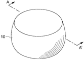
図1は、本実施の形態の立体造形物10の外観を示した斜視図である。本実施の形態の立体造形物10は、側面が湾曲して膨らんだ略円筒形状を有している。立体造形物10の表面は、色を有している。なお、本発明に係る立体造形物の形状、並びに本発明に係る製造方法によって製造される立体造形物の形状は、図1に示す形状に限定されるものではなく、例えば、六面体や球型や中空構造やリング構造や蹄鉄型などあらゆる形状に適用することができる。
[Composition of 3D model]
(First Embodiment)
FIG. 1 is a perspective view showing the appearance of the three-
図2は、図1に示す立体造形物10のA−A´断面図である。立体造形物10は、内側から順に、モデル材11、反射層12、カラー層13を有している。図2に示す例では、カラー層13が最外面にある。立体造形物10のカラー層13が外部から視認される部分である。カラー層13の内側にある反射層12は、白色の層である。反射層12は、必須の構成ではないが、モデル材11のすぐ上にカラー層13を設けると、モデル材11の色が外部から視認される可能性があるので、白色の反射層12を設けることが望ましい。
FIG. 2 is a cross-sectional view taken along the line AA'of the three-
本実施の形態の立体造形物10では、カラー層13は、3つの層を有している。説明の便宜上、3つの層を内側から順に、第1層14、第2層15、第3層16と呼ぶこととする。
In the three-
図3(a)は、図2の断面図のB部分を拡大した図である。図3(a)に示すように、第1層14は複数のカラーインクのドット17を含み、第2層15は複数のカラーインクのドット18を含み、第3層16は複数のカラーインクのドット19を含んでいる。カラーインクのドット17〜19の間は、透明インク20が充填されている。カラーインク及び透明インクは、いずれも紫外線硬化性インクであり、インクを着弾させた後、紫外線を照射することによって硬化される。
FIG. 3A is an enlarged view of a portion B in the cross-sectional view of FIG. As shown in FIG. 3A, the
カラーインクのドット17〜19は、第1層14に含まれるカラーインクのドット17が最も大きく、第2層15のカラーインクのドット18、第3層16のカラーインクのドット19の順に、すなわち外側に近くなるにしたがって、サイズが小さくなっている。なお、第1層14〜第3層16のそれぞれの層の中では、用いられるカラーインクのドットのサイズは一定である。
As for the
本実施の形態では、カラーインクのドット密度は第1層14〜第3層16を通じて一定である。つまり、カラーインクの割合を小さくするために、ドット密度を制御するのではなく、各位置に着弾するカラーインクの量を制御する。このように、カラーインクのドット17〜19のサイズを外側に近くになるにしたがって小さくする構成により、外側の方がカラーインクの割合が小さくなり、透明インクの割合が大きくなる。
In this embodiment, the dot density of the color ink is constant throughout the
本実施の形態の立体造形物10は、外側に近くなるほど透明インクの割合が大きくなる構成により、カラー層13の外側に近い部分では、カラードット19で反射した光線が拡散する。外側に近いドットほど、その形状を視認しやすいところ、透明インク20によって光が拡散されるので、立体造形物10の表面の粒状感が良くなる。
In the three-
また、カラー層13の外側において透明インク20の割合が大きく、内側においてカラーインクの割合が大きい構成であるため、立体造形物10の表面が削れたときにも、色が落ちにくい。
Further, since the ratio of the
図3(b)は、第1の実施の形態の変形例に係る立体造形物10の構成を示す断面図である。第1の実施の形態の変形例に係る立体造形物10は、第1層14と第2層15との間、及び、第2層15と第3層16との間に、透明インクからなる層21が介在している。このように第2層15と第3層16との間に透明インクの層21を有することで、第2層15のカラーインクのドット18の視認性を低下させ、粒状感を良くすることができる。最も大きいサイズのドットを有する第1層14についても同様に、透明インクの層21により、粒状感を良くすることができる。
FIG. 3B is a cross-sectional view showing the configuration of the three-
(第2の実施の形態)
次に、本発明の第2の実施の形態の立体造形物10について説明する。第2の実施の形態の立体造形物10の基本的な構成は、第1の実施の形態の立体造形物10と同じであるが(図1,図2参照)、第2の実施の形態の立体造形物10は、カラー層13において、外側のカラーインクの割合を小さくする構成が異なる。
(Second Embodiment)
Next, the three-
図4(a)は、第2の実施の形態の立体造形物10の部分断面図である。図4(a)に示すように、第2の実施の形態の立体造形物10のカラー層13の第1層14〜第3層16はそれぞれ、複数のカラーインク17〜19のドットを含んでおり、カラーインクの間は、透明インク20が充填されている。カラーインクのドット17〜19のサイズは、第1層14〜第3層16のいずれでも同じである。ただし、第1層14に含まれるカラーインクのドット17の密度が最も大きく、第2層15のカラーインクのドット18、第3層16のカラーインクのドット19の順に、すなわち外側に近くなるにしたがって、カラーインクのドット密度が低下している。なお、第1層14〜第3層16のそれぞれの層の中では、用いられるカラーインクのドットの密度は一定である。
FIG. 4A is a partial cross-sectional view of the three-
ここで、第2の実施の形態の立体造形物10におけるカラーインクのドット17〜19について、第1の実施の形態と対比して説明する。図5(a)は、第1の実施の形態の立体造形物10のカラーインクのドット17〜19を示し、図5(b)は、第2の実施の形態の立体造形物10のカラーインクのドット17〜19を示す図である。図5(a)に示すように、第1の実施の形態では、カラーインクのドットの密度は第1層14〜第3層16で同じであるが、各ドットのサイズが異なる。これに対し、第2の実施の形態では、ドットのサイズは第1層14〜第3層16で同じであるが、ドットの密度が異なる。つまり、第2の実施の形態では、カラー層13は、外側にいくにしたがってカラードットが間引かれている。
Here, the
このように、カラーインクのドットの密度を外側に近くになるにしたがって小さくする構成により、外側の方がカラーインクの割合が小さくなり、透明インク20の割合が大きくなる。これにより、第1の実施の形態の立体造形物10と同様に、立体造形物10の表面の粒状感が良くなる。
As described above, by reducing the density of the dots of the color ink as it gets closer to the outside, the ratio of the color ink becomes smaller and the ratio of the
また、カラー層13の外側において透明インク20の割合が大きく、内側においてカラーインクの割合が大きい構成であるため、立体造形物10の表面が削れたときにも、色が落ちにくい。
Further, since the ratio of the
図4(b)は、第2の実施の形態の変形例に係る立体造形物10の構成を示す断面図である。第2の実施の形態の変形例に係る立体造形物10は、第1層14と第2層15との間、及び、第2層15と第3層16との間に、透明インクからなる層21が介在している。このように第2層15と第3層16との間に透明インクの層21を有することで、第2層15のカラーインクのドット18の視認性を低下させ、粒状感を良くすることができる。最も大きいサイズのドットを有する第1層14についても同様に、透明インクの層21により、粒状感を良くすることができる。
FIG. 4B is a cross-sectional view showing the configuration of the three-
(第3の実施の形態)
次に、本発明の第3の実施の形態の立体造形物10について説明する。第3の実施の形態の立体造形物10の基本的な構成は、第1の実施の形態の立体造形物10と同じであるが(図1,図2参照)、第3の実施の形態の立体造形物10は、カラー層13において、外側のカラーインクの割合を小さくする構成が異なる。
(Third Embodiment)
Next, the three-
図6は、第3の実施の形態の立体造形物10の部分断面図である。図6に示すように、第3の実施の形態の立体造形物10のカラー層13の第1層14〜第3層16は、複数のカラーインクのドット17〜19を含んでおり、カラーインクのドット17〜19の間は、透明インク20が充填されている。カラーインクのドット17〜19のサイズ及びドット密度は、第1層14〜第3層16のいずれでも同じである。第1層14と第2層15との間、第2層15と第3層16との間には、透明インクからなる層21が介在されている。透明インクからなる層21は、外側の方が厚い。すなわち、第1層14と第2層15との間に介在された透明インクの層21よりも、第2層15と第3層16との間に介在された透明インクの層21の方が厚い。
FIG. 6 is a partial cross-sectional view of the three-
この構成により、第1層14〜第3層16のカラーインクのドット17〜19のサイズ及びドット密度は同じであるが、透明インクの層21を合わせた範囲では、カラー層13は、外側に行くにしたがって、カラーインクの割合が小さくなっている。
With this configuration, the sizes and dot densities of the
このように、外側の方がカラーインクの割合を小さくする構成により、外側の方が透明インク20の割合が大きくなる。これにより、第1の実施の形態の立体造形物10と同様に、立体造形物10の表面の粒状感が良くなる。
As described above, due to the configuration in which the ratio of the color ink is smaller on the outer side, the ratio of the
また、カラー層13の外側において透明インクの割合が大きく、内側においてカラーインクの割合が大きい構成であるため、立体造形物10の表面が削れたときにも、色が落ちにくい。
Further, since the ratio of the transparent ink is large on the outside of the
(第4の実施の形態)
次に、本発明の第4の実施の形態の立体造形物10について説明する。第4の実施の形態の立体造形物10の基本的な構成は、第1の実施の形態の立体造形物10と同じである(図1,図2参照)。
(Fourth Embodiment)
Next, the three-
図7(a)は、第4の実施の形態の立体造形物10の部分断面図である。図7(a)に示すように、第4の実施の形態の立体造形物10は、第1の実施の形態のカラー層13の構成に加えて、最外面に透明インクの層21を備えている。このように最外面に透明インクの層21を備えることにより、光が拡散されるので、立体造形物10の表面の粒状感が良くなる。また、最外面の透明インクの層21が削れたときにも、色が落ちにくい。
FIG. 7A is a partial cross-sectional view of the three-
なお、図7(a)では、第1の実施の形態の立体造形物10において、カラー層13の最外面に透明インクの層21を備える例を挙げたが、上記した他の実施の形態に係る立体造形物10において、カラー層13の最外面に透明インクの層21を備えてもよい。図7(b)は、第2の実施の形態の立体造形物10において、カラー層13の最外面に透明インクの層21を設けた例を示す図である。この構成によっても、立体造形物10の表面の粒状感をなくし、最外面の透明インクの層21が削れたときの色落ちを低減できる。
In addition, in FIG. 7A, an example in which the
なお、上記した実施の形態では、カラー層13を複数の層で構成する例を挙げて説明したが、本発明の立体造形物10は、必ずしも、同じドットサイズまたは同じドット密度を有する層によって構成する必要はない。
In the above-described embodiment, the
図8(a)は、外側にいくにしたがってカラーインクのドット17のサイズを小さくしたカラー層13の構成を示す図であり、図8(b)は、外側にいくにしたがってカラーインクのドット密度を小さくしたカラー層13の構成を示す図である。このように、カラー層13を複数の層で構成することなく、外側にいくほどカラーインクの割合を小さくする構成としても、上記した実施の形態と同様に、立体造形物10の表面の粒状感をなくし、最外面の透明インクの層21が削れたときの色落ちを低減する効果が得られる。
FIG. 8A is a diagram showing the configuration of the
[立体造形物製造装置]
次に、上記した実施の形態の立体造形物10を製造する立体造形物製造装置30の構成について説明する。
図9は、立体造形物製造装置30の構成を示す図である。立体造形物製造装置30は、インクジェットヘッドから噴射した紫外線硬化インクを、紫外線で固めて積層するインクジェット方式の3Dプリンタである。立体造形物製造装置30は、吐出ユニット31、主走査駆動部32、造形台33、制御部34、及び入力部35を備える。吐出ユニット31は、立体造形物10の材料となる液滴(インク滴)を吐出する部分である。なお、立体造形物製造装置30は、紫外線硬化インクを用いたものに限らず、インクジェットヘッドから高温状態で噴射し、常温に冷やして硬化させる熱可塑性の硬化性樹脂を積層する方式であっても良い。
[Three-dimensional model manufacturing equipment]
Next, the configuration of the three-dimensional
FIG. 9 is a diagram showing the configuration of the three-dimensional
吐出ユニット31は、有色および無色のインクや、サポート用材料を含むインクを吐出するインクヘッド40と、吐出したインクを硬化させる紫外線光源41と、立体造形物10の造形中に形成される硬化性樹脂の積層面を平坦化する平坦化ローラ42を有している。ここでは、インクヘッド40を3つ示しているが、インクヘッド40の数は、使用するインクの種類の数に応じて、適宜の数とすることができる。
The
吐出ユニット31は、例えば、紫外線の照射により硬化する硬化性樹脂のインク滴等を吐出し、硬化させることにより、立体造形物10を構成する各層を形成する。具体的には、吐出ユニット31は、例えば、制御部34の指示に応じてインク滴を吐出することにより、硬化性樹脂の層を形成する層形成動作と、層形成動作で形成された硬化性樹脂の層を硬化させる硬化動作とを複数回繰り返して行う。これにより、吐出ユニット31は、硬化した硬化性樹脂の層を複数層重ねて形成する。吐出ユニット31は、印刷媒体に着弾させる一つのドットの大きさを、数段階に制御することができるバリアブルドット方式を採用している。
The
主走査駆動部32は、吐出ユニット31に主走査動作を行わせる駆動部である。ここで、主走査動作とは、例えば、予め設定された主走査方向(図中のY方向)へ移動しつつインク滴を吐出する動作である。
The main
主走査駆動部32は、キャリッジ43及びガイドレール44を有する。キャリッジ43は、吐出ユニット31を造形台33と対向させて保持する保持部である。つまり、キャリッジ43は、インク滴の吐出方向が造形台33へ向かう方向になるように、吐出ユニット31を保持する。また、主走査動作時において、キャリッジ43は、吐出ユニット31を保持した状態で、ガイドレール44に沿って移動する。ガイドレール44は、キャリッジ43の移動をガイドするレール状部材であり、主走査動作時において、制御部34の指示に応じて、キャリッジ43を移動させる。
The main
尚、主走査動作における吐出ユニット31の移動は、立体造形物10に対する相対的な移動であってよい。例えば、吐出ユニット31の位置を固定して、例えば造形台33を移動させることにより、立体造形物10の側を移動させてもよい。
The movement of the
造形台33は、載置台の一例であり、造形中の立体造形物10を載置する。造形台33は、上面を上下方向(図中のZ方向)へ移動させる機能を有しており、制御部34の指示に応じて、立体造形物10の造形の進行に合わせて、上面を移動させる。また、これにより、造形途中の立体造形物10における被造形面と、吐出ユニット31との間の距離(ギャップ)を適宜調整する。ここで、立体造形物10の被造形面とは、例えば、吐出ユニット31により次の層が形成される面のことである。尚、吐出ユニット31に対して造形台33を上下動させるZ方向への走査は、例えば吐出ユニット31の側を移動させることで行ってもよい。
The modeling table 33 is an example of a mounting table, and mounts the three-
制御部34は、例えば立体造形物製造装置30のCPUであり、造形すべき立体造形物10の形状情報や、カラー画像情報等に基づいて立体造形物製造装置30の各部を制御することにより、立体造形物10の造形の動作を制御する。
The
また、制御部34は、設計データ生成部45を有しており、入力部35から入力された立体造形物1030の3次元データに基づいて、設計データを生成する機能を有している。設計データの生成の動作については、後述する。制御部34は、生成した設計データに基づいて、立体造形物10の造形の動作を制御する。
Further, the
尚、立体造形物製造装置30は、図9に図示した構成以外にも、例えば、立体造形物10の造形や着色等に必要な各種構成を更に備えてよい。例えば、立体造形物製造装置30は、吐出ユニット31に副走査動作を行わせる副走査駆動部等を更に備えてもよい。副走査動作とは、例えば、造形中の立体造形物10に対して相対的に、主走査方向と直交する副走査方向へ、吐出ユニット31におけるインクジェットヘッドを移動させる動作である。副走査駆動部は、例えば、副走査方向における長さが吐出ユニット31におけるインクジェットヘッドの造形幅よりも長い立体造形物10を造形する場合等に、必要に応じて、吐出ユニット31に副走査動作を行わせる。また、副走査駆動部は、例えば、吐出ユニット31を保持するキャリッジと共にガイドレールを移動させる駆動部であってもよい。
In addition to the configuration shown in FIG. 9, the three-dimensional
[立体造形物製造方法]
図10は、立体造形物製造装置30によって立体造形物10を製造する動作を示すフローチャートである。立体造形物製造装置30は、まず、製造すべき立体造形物10の3次元モデルのデータを入力する(S10)。次に、3次元モデルのデータに基づいて設計データを生成する。
[Three-dimensional model manufacturing method]
FIG. 10 is a flowchart showing an operation of manufacturing the three-
図11は、3次元モデルから設計データを生成する過程を示す模式図である。立体造形物製造装置30の設計データ生成部45は、3次元モデルの各面に対し、内側に垂直な方向(すなわち、反転した面法線ベクトル)を求める(S11)。図11(a)に、各面に対して、反転した面法線ベクトルを求めた例を示す。
FIG. 11 is a schematic diagram showing a process of generating design data from a three-dimensional model. The design
続いて、設計データ生成部45は、反転した面法線方向に一定の厚みを有するカラー層13を設計する(S12)。図11(b)は、各面に対してカラー層13を設計した例を示す。この際、カラー層13は複数の層で構成し、カラー層13を構成する各層におけるカラーインクの割合を決定する。なお、図10及び図11では示していないが、立体造形物10が反射層12を有する場合には、カラー層13の内側に反射層12を設計する処理を行う。
Subsequently, the design
次に、設計データ生成部45は、カラー層13が設計された3次元モデルをインクの積層サイズでスライスし、各層のスライス画像を生成する(S13)。ここで、積層サイズとは、吐出ユニット31を1回走査してカラーインク及び透明インクを吐出して紫外線硬化させて生成する一つの層である。図11(c)は、3次元モデルをスライスする層を示し、図11(d)はスライスして得られたスライス画像の例を示す図である。
Next, the design
次に、設計データ生成部45は、誤差拡散法や組織的ディザ法などを用いてカラー層13をプリンタのインク情報に変換し、カラー層13を構成するカラーインクの着弾位置及びドットサイズを決定する(S14)。カラー層13は、複数の層から構成され、層ごとにカラーインクの割合が決定されているので、カラーインクの割合に合うようにカラーインクのサイズ及びドットサイズを設計する。そして、立体造形物製造装置30は、生成した設計データに基づいて、積層処理を行う(S15)。
Next, the design
カラー層13を積層する際には、立体造形物製造装置30は、設計された位置にカラーインクを着弾させて紫外線硬化させる。続いて、カラーインクの隙間に十分な量の透明インクを着弾させた上で、余剰の透明インクは平坦化ローラ42でかきとって、カラーインクの隙間を充填し、紫外線硬化させる。
When laminating the
第1の実施の形態のカラー層13を形成する際には、外側にいくにしたがって、ドットサイズが小さくなるが、吐出ヘッド40は、バリアブルドットの機能を有するので、外側に行くにしたがって、ドットサイズを小さくすることができる。第2の実施の形態のカラー層13を形成する際には、設計データ生成部45にて設計データを生成する際に、外側にいくほどドット密度が低下するようにカラーインクの着弾位置が設計されているので、当該設計データにしたがってカラーインクを着弾することにより、ドット密度を制御できる。
When the
以上、本発明の実施の形態の立体造形物、立体造形物製造装置、及び立体造形物製造方法について説明したが、本発明は上記した実施の形態に限定されるものではない。本発明の立体造形物は、カラーインクのサイズとドット密度の両方を制御して、外側になるにしたがってカラーインクの割合を小さくした構成としてもよい。 Although the three-dimensional model, the three-dimensional model manufacturing apparatus, and the method for manufacturing the three-dimensional model according to the embodiment of the present invention have been described above, the present invention is not limited to the above-described embodiment. The three-dimensional model of the present invention may have a configuration in which both the size and the dot density of the color ink are controlled, and the proportion of the color ink is reduced toward the outside.
(実施の形態の効果)
(1)第1の実施の形態乃至第4の実施の形態の立体造形物10は、紫外線硬化性インクによって構成された立体造形物10であって、表面にカラー層13を有し、カラー層13は、カラーインクとカラーインク間を充填する透明インク20とで構成された層であって、外側に近くなるにしたがって透明インクに占めるカラーインクの割合が小さくなっている構成を有する。この構成により、カラー層13の外側に近い部分では、カラードット17〜19で反射した光線が透明インク20によって拡散するので、立体造形物10の表面の粒状感が良くなる。
(Effect of embodiment)
(1) The three-
(2)第1の実施の形態乃至第4の実施の形態の立体造形物10は、カラー層13の内側に、光反射性を有する反射層を備えてもよい。この構成により、カラー層13の色が後ろにあるモデル材11の色に邪魔されることなく外部から視認され、所望のカラーを忠実に実現できる。
(2) The three-
(3)第1の実施の形態の立体造形物10において、カラー層13は、外側に近くなるにしたがって、カラーインクのドット17〜19のサイズが小さくなっていてもよい。この構成により、透明インク20に占めるカラーインクの割合を小さくすることができる。
(3) In the three-
(4)第1の実施の形態の立体造形物10において、カラー層13は複数の層14〜16から構成されており、層14〜16のそれぞれの中では、カラーインクのドットサイズが同じであってもよい。この構成により、層14〜16ごとにカラーインクのドット17〜19のサイズを設計できる。
(4) In the three-
(5)第2の実施の形態の立体造形物10において、カラー層13は、外側に近くなるにしたがって、カラーインクのドット17〜19の密度が小さくなっていてもよい。この構成により、透明インク20に占めるカラーインクの割合を小さくできる。
(5) In the three-
(6)第2の実施の形態の立体造形物10において、カラー層13は複数の層14〜16から構成されており、層14〜16のそれぞれの中では、カラーインクが同じ密度で含まれていてもよい。この構成により、層14〜16ごとにカラーインクのドット17〜19の密度を設計できる。
(6) In the three-
(7)第1の実施の形態の変形例または第2の実施の形態の変形例にかかる立体造形物10において、カラー層13を構成する複数の層14〜16の間に透明インクからなる層21が介在されていてもよい。この構成により、透明インクからなる層21の内側にあるカラー層13からの光線を分散することで、粒状感が良くなる。
(7) In the three-
(8)第3の実施の形態の立体造形物10において、カラー層13は複数の層から構成されると共に、複数の層14〜16の間には透明インクからなる層21が介在されており、透明インクからなる層21は、外側にある層の方が内側にある層よりも厚い構成を有してもよい。この構成により、カラー層13の構成が一様であっても、透明インクからなる層21と合わせて、外側の方が、カラーインクの割合が小さくなるように構成できる。
(8) In the three-
(9)第4の実施の形態の立体造形物10において、カラー層13は、最外面に透明インクからなる層21を備えてもよい。この構成により、カラー層13にあるカラーインクからの光線を最外面の透明インクの層21で分散して、粒状感が良くなる。
(9) In the three-
(10)実施の形態の立体造形物製造方法は、紫外線硬化性インクを用いて積層造形法により立体造形物10を造形する立体造形物製造方法であって、立体造形物10の3次元データに基づいて、立体造形物10の表面から内側に所定の厚みを有するカラー層13を設計する工程と、立体造形物10の3次元データを紫外線硬化性インクの積層サイズでスライスし、各レイヤの設計データであるスライス画像を生成する工程と、スライス画像において、カラー層13を構成するカラーインクの量を、外側に近くなるにしたがって透明インクに占めるカラーインクの割合が小さくなるように設計する工程と、スライス画像のデータに基づいて紫外線硬化性インクの積層を行う工程とを備える。
(10) The three-dimensional model manufacturing method of the embodiment is a three-dimensional model manufacturing method in which the three-
この方法により、立体造形物10の3次元データに基づいて、外側に近くなるにしたがって透明インク20に占めるカラーインクの割合が小さくなるようなカラー層13を設計し、当該設計データに基づいてカラー層13を生成することができる。これにより、カラー層13の外側に近い部分では、カラードットで反射した光線が透明インクによって拡散するので、立体造形物10の表面の粒状感が良くなる。
By this method, based on the three-dimensional data of the three-
(11)実施の形態の立体造形物製造方法において、積層を行う工程では、カラー層13を構成するカラーインクの量に応じて、カラーインクのドット17〜19のサイズを調整してもよい。この構成により、透明インク20に占めるカラーインクの割合を小さくすることができる。
(11) In the three-dimensional model manufacturing method of the embodiment, in the step of laminating, the size of the
(12)実施の形態の立体造形物製造方法において、積層を行う工程では、カラー層13を構成するカラーインクの量に応じて、カラーインクのドット17〜19の密度を調整してもよい。この構成により、透明インク20に占めるカラーインクの割合を小さくできる。
(12) In the three-dimensional model manufacturing method of the embodiment, in the step of laminating, the density of the
(13)実施の形態の立体造形物製造装置30は、紫外線硬化性インクを用いて積層造形法により立体造形物10を造形する立体造形物製造装置30であって、立体造形物10の3次元データを取り込む入力部35と、入力部35にて入力された3次元データに基づいて、各レイヤの設計データを生成する設計データ生成部45と、設計データに基づいて積層を行う吐出ユニット31、主走査駆動部32及び造形台33等からなる積層部とを備え、設計データ生成部45は、立体造形物10の3次元データに基づいて、立体造形物10の表面から内側に所定の厚みを有するカラー層13を設計する処理と、立体造形物10の3次元データを紫外線硬化性インクの積層サイズでスライスし、各レイヤの設計データであるスライス画像を生成する処理と、スライス画像において、カラー層13を構成するカラーインクの量を、外側に近くなるにしたがって透明インクに占めるカラーインクの割合が小さくなるように設計する処理とを行う。
(13) The three-dimensional
この構成により、立体造形物10の3次元データに基づいて、外側に近くなるにしたがって透明インク20に占めるカラーインクの割合が小さくなるようなカラー層13を設計し、当該設計データに基づいてカラー層13を生成することができる。これにより、カラー層13の外側に近い部分では、カラードット17〜19で反射した光線が透明インク20によって拡散するので、立体造形物10の表面の粒状感が良くなる。
With this configuration, based on the three-dimensional data of the three-
(14)実施の形態の立体造形物製造装置30において、積層部は、カラー層13を構成するカラーインクの量に応じて、カラーインクのドット17〜19のサイズを調整してもよい。この構成により、透明インク20に占めるカラーインクの割合を小さくすることができる。
(14) In the three-dimensional
(15)実施の形態の立体造形物製造装置30において、積層部は、カラー層13を構成するカラーインクの量に応じて、カラーインクのドット17〜19の密度を調整してもよい。この構成により、透明インク20に占めるカラーインクの割合を小さくできる。
(15) In the three-dimensional
本発明は、3Dプリンタ等によって、色を有する立体造形物を製造する方法として有用である。 The present invention is useful as a method for producing a three-dimensional model having color by using a 3D printer or the like.
10 立体造形物
11 モデル材
12 反射層
13 カラー層
14 第1層
15 第2層
16 第3層
17〜19 カラーインクのドット
20 透明インク
21 透明インクの層
30 立体造形物製造装置
31 吐出ユニット
32 主走査駆動部
33 造形台
34 制御部
35 入力部
40 インクヘッド
41 紫外線光源
42 平坦化ローラ
43 キャリッジ
44 ガイドレール
45 設計データ生成部
10 Three-
Claims (15)
表面にカラー層を有し、
前記カラー層は、カラーインクと前記カラーインク間を充填する透明インクとで構成された層であって、外側に近くなるにしたがって前記透明インクに占める前記カラーインクの割合が小さくなっている立体造形物。 It is a three-dimensional model composed of curable ink.
Has a color layer on the surface
The color layer is a layer composed of a color ink and a transparent ink that fills the space between the color inks, and the ratio of the color ink to the transparent ink decreases as it gets closer to the outside. object.
前記立体造形物の3次元データに基づいて、前記立体造形物の表面から内側に所定の厚みを有するカラー層を設計する工程と、
前記立体造形物の3次元データを前記硬化性インクの積層サイズでスライスし、各レイヤの設計データであるスライス画像を生成する工程と、
前記スライス画像において、前記カラー層を構成するカラーインクの量を、外側に近くなるにしたがって前記透明インクに占める前記カラーインクの割合が小さくなるように設計する工程と、
前記スライス画像のデータに基づいて硬化性インクの積層を行う工程と、
を備える立体造形物製造方法。 It is a three-dimensional model manufacturing method that uses curable ink to create a three-dimensional model by additive manufacturing.
A process of designing a color layer having a predetermined thickness inside from the surface of the three-dimensional model based on the three-dimensional data of the three-dimensional model.
A step of slicing the three-dimensional data of the three-dimensional model with the laminated size of the curable ink to generate a slice image which is design data of each layer.
In the slice image, a step of designing the amount of the color ink constituting the color layer so that the ratio of the color ink to the transparent ink decreases as it gets closer to the outside.
A step of laminating curable ink based on the slice image data, and
A method for manufacturing a three-dimensional model.
前記立体造形物の3次元データを取り込む入力部と、
前記入力部にて入力された前記3次元データに基づいて、各レイヤの設計データを生成する設計データ生成部と、
前記設計データに基づいて積層を行う積層部と、
を備え、
前記設計データ生成部は、
前記立体造形物の3次元データに基づいて、前記立体造形物の表面から内側に所定の厚みを有するカラー層を設計する処理と、
前記立体造形物の3次元データを前記硬化性インクの積層サイズでスライスし、各レイヤの設計データであるスライス画像を生成する処理と、
前記スライス画像において、前記カラー層を構成するカラーインクの量を、外側に近くなるにしたがって前記透明インクに占める前記カラーインクの割合が小さくなるように設計する処理と、
を行う立体造形物製造装置。 It is a three-dimensional modeling device that models a three-dimensional model by the laminated modeling method using curable ink.
An input unit that captures 3D data of the three-dimensional model,
A design data generation unit that generates design data for each layer based on the three-dimensional data input by the input unit.
A laminated portion for laminating based on the design data and
With
The design data generation unit
A process of designing a color layer having a predetermined thickness inside from the surface of the three-dimensional model based on the three-dimensional data of the three-dimensional model.
A process of slicing the three-dimensional data of the three-dimensional model with the laminated size of the curable ink to generate a slice image which is design data of each layer.
In the slice image, a process of designing the amount of the color ink constituting the color layer so that the ratio of the color ink to the transparent ink decreases as it gets closer to the outside.
A three-dimensional model manufacturing device that performs
The three-dimensional modeling device according to claim 13, wherein the laminated portion adjusts the dot density of the color ink according to the amount of the color ink constituting the color layer.
Priority Applications (2)
| Application Number | Priority Date | Filing Date | Title |
|---|---|---|---|
| JP2016207113A JP6773517B2 (en) | 2016-10-21 | 2016-10-21 | Three-dimensional model, three-dimensional model manufacturing method, and three-dimensional model manufacturing equipment |
| US15/788,309 US10421235B2 (en) | 2016-10-21 | 2017-10-19 | Three-dimensional object, method for producing three-dimensional object, and three-dimensional object production apparatus |
Applications Claiming Priority (1)
| Application Number | Priority Date | Filing Date | Title |
|---|---|---|---|
| JP2016207113A JP6773517B2 (en) | 2016-10-21 | 2016-10-21 | Three-dimensional model, three-dimensional model manufacturing method, and three-dimensional model manufacturing equipment |
Publications (2)
| Publication Number | Publication Date |
|---|---|
| JP2018065352A JP2018065352A (en) | 2018-04-26 |
| JP6773517B2 true JP6773517B2 (en) | 2020-10-21 |
Family
ID=61971226
Family Applications (1)
| Application Number | Title | Priority Date | Filing Date |
|---|---|---|---|
| JP2016207113A Active JP6773517B2 (en) | 2016-10-21 | 2016-10-21 | Three-dimensional model, three-dimensional model manufacturing method, and three-dimensional model manufacturing equipment |
Country Status (2)
| Country | Link |
|---|---|
| US (1) | US10421235B2 (en) |
| JP (1) | JP6773517B2 (en) |
Families Citing this family (4)
| Publication number | Priority date | Publication date | Assignee | Title |
|---|---|---|---|---|
| US11890816B2 (en) | 2018-07-30 | 2024-02-06 | Stratasys Ltd. | System and method of mitigating color offset discrepancies in 3D printing systems |
| JP7217617B2 (en) * | 2018-11-15 | 2023-02-03 | 株式会社ミマキエンジニアリング | Modeling apparatus and modeling method |
| US11633919B2 (en) | 2019-06-12 | 2023-04-25 | Stratasys Ltd. | System and method for three-dimensional printing |
| JP7357879B2 (en) | 2020-01-28 | 2023-10-10 | 株式会社ミマキエンジニアリング | Colored product manufacturing method and ink ejection device |
Family Cites Families (5)
| Publication number | Priority date | Publication date | Assignee | Title |
|---|---|---|---|---|
| US20040080078A1 (en) * | 2002-10-25 | 2004-04-29 | Collins David C. | Methods and systems for producing a desired apparent coloring in an object produced through rapid prototyping |
| JP2015182426A (en) * | 2014-03-26 | 2015-10-22 | セイコーエプソン株式会社 | Method for manufacturing three-dimensional molded article and three-dimensional molded article |
| JP6434727B2 (en) * | 2014-07-07 | 2018-12-05 | 株式会社ミマキエンジニアリング | Three-dimensional object forming method and three-dimensional object forming apparatus |
| JP6485005B2 (en) * | 2014-11-12 | 2019-03-20 | セイコーエプソン株式会社 | Three-dimensional object modeling device |
| JP6500483B2 (en) * | 2015-02-19 | 2019-04-17 | セイコーエプソン株式会社 | Three-dimensional object formation device, control method for three-dimensional object formation device, and control program for three-dimensional object formation device |
-
2016
- 2016-10-21 JP JP2016207113A patent/JP6773517B2/en active Active
-
2017
- 2017-10-19 US US15/788,309 patent/US10421235B2/en not_active Expired - Fee Related
Also Published As
| Publication number | Publication date |
|---|---|
| JP2018065352A (en) | 2018-04-26 |
| US20180111323A1 (en) | 2018-04-26 |
| US10421235B2 (en) | 2019-09-24 |
Similar Documents
| Publication | Publication Date | Title |
|---|---|---|
| US10065376B2 (en) | Three-dimensional object fabrication device, three-dimensional object fabrication method, and three-dimensional object | |
| US11135762B2 (en) | Shaped article, and manufacturing method for the shaped article | |
| JP6396723B2 (en) | Droplet discharge apparatus and droplet discharge method | |
| JP6773517B2 (en) | Three-dimensional model, three-dimensional model manufacturing method, and three-dimensional model manufacturing equipment | |
| JP6888002B2 (en) | Modeling equipment, modeling method, and modeled object | |
| WO2016190342A1 (en) | Three-dimensional molded object production method and molding device | |
| JP6836897B2 (en) | Modeled object and modeling method | |
| JP6902365B2 (en) | 3D modeling method and 3D printer | |
| JP2018024117A (en) | Molding method, molding system and molding apparatus | |
| JP6725361B2 (en) | Modeling method and modeling device for three-dimensional object | |
| JP2018012278A (en) | Solid body molding method, and solid body molding device | |
| JP2018065308A (en) | Molding apparatus and molding method | |
| JP6629152B2 (en) | Modeling apparatus and modeling method | |
| JP6823435B2 (en) | Modeling equipment and modeling method | |
| JP2016107637A (en) | Apparatus for molding three-dimensional object and method for molding three-dimensional object | |
| US10996653B2 (en) | Three-dimensional object building device, three-dimensional object building method, and method of producing three-dimensional object | |
| JP6659284B2 (en) | 3D decorative molding equipment | |
| JP7350461B2 (en) | Modeled object | |
| JP6699941B2 (en) | Modeling apparatus and modeling method | |
| JP6261363B2 (en) | Model and manufacturing method thereof | |
| WO2016006551A1 (en) | Three-dimensional object molding device and three-dimensional object molding method | |
| JP2021115796A (en) | Manufacturing method of coloring product and ink discharge device | |
| JP2021094821A (en) | Molding device and molding method | |
| WO2021125028A1 (en) | Molding device, clear ink compensation amount input method, and molding method | |
| JP7145046B2 (en) | Modeling apparatus and modeling method |
Legal Events
| Date | Code | Title | Description |
|---|---|---|---|
| A621 | Written request for application examination |
Free format text: JAPANESE INTERMEDIATE CODE: A621 Effective date: 20190409 |
|
| A977 | Report on retrieval |
Free format text: JAPANESE INTERMEDIATE CODE: A971007 Effective date: 20200309 |
|
| A131 | Notification of reasons for refusal |
Free format text: JAPANESE INTERMEDIATE CODE: A131 Effective date: 20200317 |
|
| TRDD | Decision of grant or rejection written | ||
| A01 | Written decision to grant a patent or to grant a registration (utility model) |
Free format text: JAPANESE INTERMEDIATE CODE: A01 Effective date: 20200923 |
|
| A61 | First payment of annual fees (during grant procedure) |
Free format text: JAPANESE INTERMEDIATE CODE: A61 Effective date: 20201001 |
|
| R150 | Certificate of patent or registration of utility model |
Ref document number: 6773517 Country of ref document: JP Free format text: JAPANESE INTERMEDIATE CODE: R150 |
|
| R250 | Receipt of annual fees |
Free format text: JAPANESE INTERMEDIATE CODE: R250 |