JP6772609B2 - Representative image generator, representative image generation method and program - Google Patents
Representative image generator, representative image generation method and program Download PDFInfo
- Publication number
- JP6772609B2 JP6772609B2 JP2016139778A JP2016139778A JP6772609B2 JP 6772609 B2 JP6772609 B2 JP 6772609B2 JP 2016139778 A JP2016139778 A JP 2016139778A JP 2016139778 A JP2016139778 A JP 2016139778A JP 6772609 B2 JP6772609 B2 JP 6772609B2
- Authority
- JP
- Japan
- Prior art keywords
- image
- target object
- representative image
- person
- visibility
- Prior art date
- Legal status (The legal status is an assumption and is not a legal conclusion. Google has not performed a legal analysis and makes no representation as to the accuracy of the status listed.)
- Active
Links
Images


Classifications
-
- G—PHYSICS
- G08—SIGNALLING
- G08B—SIGNALLING OR CALLING SYSTEMS; ORDER TELEGRAPHS; ALARM SYSTEMS
- G08B13/00—Burglar, theft or intruder alarms
- G08B13/18—Actuation by interference with heat, light, or radiation of shorter wavelength; Actuation by intruding sources of heat, light, or radiation of shorter wavelength
- G08B13/189—Actuation by interference with heat, light, or radiation of shorter wavelength; Actuation by intruding sources of heat, light, or radiation of shorter wavelength using passive radiation detection systems
- G08B13/194—Actuation by interference with heat, light, or radiation of shorter wavelength; Actuation by intruding sources of heat, light, or radiation of shorter wavelength using passive radiation detection systems using image scanning and comparing systems
- G08B13/196—Actuation by interference with heat, light, or radiation of shorter wavelength; Actuation by intruding sources of heat, light, or radiation of shorter wavelength using passive radiation detection systems using image scanning and comparing systems using television cameras
- G08B13/19602—Image analysis to detect motion of the intruder, e.g. by frame subtraction
- G08B13/19613—Recognition of a predetermined image pattern or behaviour pattern indicating theft or intrusion
-
- G—PHYSICS
- G06—COMPUTING; CALCULATING OR COUNTING
- G06T—IMAGE DATA PROCESSING OR GENERATION, IN GENERAL
- G06T7/00—Image analysis
- G06T7/20—Analysis of motion
-
- G—PHYSICS
- G06—COMPUTING; CALCULATING OR COUNTING
- G06V—IMAGE OR VIDEO RECOGNITION OR UNDERSTANDING
- G06V20/00—Scenes; Scene-specific elements
- G06V20/40—Scenes; Scene-specific elements in video content
- G06V20/46—Extracting features or characteristics from the video content, e.g. video fingerprints, representative shots or key frames
-
- G—PHYSICS
- G06—COMPUTING; CALCULATING OR COUNTING
- G06V—IMAGE OR VIDEO RECOGNITION OR UNDERSTANDING
- G06V20/00—Scenes; Scene-specific elements
- G06V20/50—Context or environment of the image
- G06V20/52—Surveillance or monitoring of activities, e.g. for recognising suspicious objects
-
- G—PHYSICS
- G06—COMPUTING; CALCULATING OR COUNTING
- G06V—IMAGE OR VIDEO RECOGNITION OR UNDERSTANDING
- G06V40/00—Recognition of biometric, human-related or animal-related patterns in image or video data
- G06V40/10—Human or animal bodies, e.g. vehicle occupants or pedestrians; Body parts, e.g. hands
- G06V40/103—Static body considered as a whole, e.g. static pedestrian or occupant recognition
-
- G—PHYSICS
- G08—SIGNALLING
- G08B—SIGNALLING OR CALLING SYSTEMS; ORDER TELEGRAPHS; ALARM SYSTEMS
- G08B13/00—Burglar, theft or intruder alarms
- G08B13/18—Actuation by interference with heat, light, or radiation of shorter wavelength; Actuation by intruding sources of heat, light, or radiation of shorter wavelength
- G08B13/189—Actuation by interference with heat, light, or radiation of shorter wavelength; Actuation by intruding sources of heat, light, or radiation of shorter wavelength using passive radiation detection systems
- G08B13/194—Actuation by interference with heat, light, or radiation of shorter wavelength; Actuation by intruding sources of heat, light, or radiation of shorter wavelength using passive radiation detection systems using image scanning and comparing systems
- G08B13/196—Actuation by interference with heat, light, or radiation of shorter wavelength; Actuation by intruding sources of heat, light, or radiation of shorter wavelength using passive radiation detection systems using image scanning and comparing systems using television cameras
- G08B13/19602—Image analysis to detect motion of the intruder, e.g. by frame subtraction
- G08B13/1961—Movement detection not involving frame subtraction, e.g. motion detection on the basis of luminance changes in the image
-
- G—PHYSICS
- G06—COMPUTING; CALCULATING OR COUNTING
- G06T—IMAGE DATA PROCESSING OR GENERATION, IN GENERAL
- G06T2207/00—Indexing scheme for image analysis or image enhancement
- G06T2207/30—Subject of image; Context of image processing
- G06T2207/30196—Human being; Person
-
- G—PHYSICS
- G06—COMPUTING; CALCULATING OR COUNTING
- G06T—IMAGE DATA PROCESSING OR GENERATION, IN GENERAL
- G06T2207/00—Indexing scheme for image analysis or image enhancement
- G06T2207/30—Subject of image; Context of image processing
- G06T2207/30232—Surveillance
Description
本開示は、代表画像生成装置、代表画像生成方法及びプログラムに関する。 The present disclosure relates to a representative image generator, a representative image generation method and a program.
従来、例えば下記の特許文献1には、顔画像を検出する装置において、一連の連続画像から客観的に最もバランスの取れた正面顔像を選択して保存することが記載されている。 Conventionally, for example, Patent Document 1 below describes that in a device for detecting a face image, an objectively most balanced front face image is selected and stored from a series of continuous images.
現在、セキュリティカメラの普及が爆発的に伸びており、年間に記録される映像はすでに1兆時間を超えていると言われている。この流れは今後も加速する傾向にあり、数年後には現在の数倍の記録時間に達すると予測されている。しかし、このような現状であるにも関わらず、例えば事件発生等の有事の際は、今でもオペレータが大量に記録された映像を一つ一つ再生して確認すると言った、目視による検索をしている事例が多く、年々オペレータの人件費が増加しているという問題が生じている。 Currently, the spread of security cameras is exploding, and it is said that the number of images recorded annually has already exceeded 1 trillion hours. This trend will continue to accelerate, and it is predicted that the recording time will reach several times the current recording time in a few years. However, in spite of this situation, in the event of an emergency such as an incident, the operator still plays back and confirms a large amount of recorded images one by one. There are many cases of this, and there is a problem that the labor cost of operators is increasing year by year.
このような問題に対しては、予め禁止エリアや通過ラインを指定することで、禁止エリアへ不法侵入(侵入検知)した人や車、または指定ラインを通過(ライン検知)した人や車などを検知する機能を使うことが想定される。このような侵入検知機能を利用すれば、検索時間を削減することが可能であり、これらの侵入検知機能を監視カメラ内、または映像を記録して管理するサーバ内に搭載することで、オペレータの作業負荷軽減を実現することができる。 For such problems, by designating the prohibited area and passing line in advance, people and cars that have illegally entered the prohibited area (intrusion detection), or people and cars that have passed the designated line (line detection), etc. It is expected to use the detection function. By using such intrusion detection, it is possible to reduce the search time, by mounting these intrusion detection in the monitoring camera, or in the server to manage the recorded video, the operator It is possible to reduce the workload of.
しかしながら、このような侵入検知機能を利用したとしても、検知した人や車が画像中に小さく写っている場合や検知した人や車が画像中で適切な方向を向いていない場合は、検知した人や車の素性を特定することは困難である。 However, even if such an intrusion detection function is used, it is detected if the detected person or car is small in the image or if the detected person or car is not facing the appropriate direction in the image. It is difficult to identify the identity of a person or car.
上述した特許文献1に記載された技術は、顔画像を検出する装置において、一連の連続画像から客観的に最もバランスの取れた正面顔像を選択して保存するものであり、監視カメラ等によって動体検知される対象物体が確実に判別できるように画像を取得することは何ら想定していない。 The technique described in Patent Document 1 described above is for detecting a face image, objectively selecting and storing the most balanced front face image from a series of continuous images, and using a surveillance camera or the like. It is not assumed that an image will be acquired so that the target object whose motion is detected can be reliably identified.
そこで、動体検知される対象物体が明らかとなるように、対象物体の最適な代表画像を生成することが求められていた。 Therefore, it has been required to generate an optimum representative image of the target object so that the target object to be detected as a moving object becomes clear.
本開示によれば、動画映像を取得し、動体検知により前記動画映像の中から対象物体を検知する検知部と、前記検知部が前記対象物体を検知した後、前記動画映像中で移動する前記対象物体を追尾する追尾部と、前記検知部が前記対象物体を検知した後、前記追尾部が追尾した前記対象物体を示す代表画像を作成する代表画像作成部と、を備え、前記代表画像作成部は、予め指定された時間帯において取得された前記動画映像に基づき前記代表画像を生成し、前記検知部は、前記時間帯の最終フレームで前記対象物体の前記検知を終了させる、代表画像生成装置が提供される。 According to the present disclosure, a detection unit that acquires a moving image and detects a target object from the moving object by motion detection, and a detection unit that moves in the moving image after the detection unit detects the target object. The representative image creation unit includes a tracking unit that tracks the target object and a representative image creation unit that creates a representative image showing the target object that the tracking unit has tracked after the detection unit detects the target object. parts generates the representative image based on the moving image acquired in pre-specified time period, the detection unit, Ru terminates the detection of the target object in the last frame of the time period, a representative image A generator is provided.
前記追尾部が前記対象物体を追尾している間、前記対象物体の視認性を演算する視認性演算部を備え、前記代表画像作成部は、前記視認性演算部が前記対象物体の視認性を演算した結果に基づいて前記代表画像を作成するものであっても良い。 The tracking unit includes a visibility calculation unit that calculates the visibility of the target object while the tracking unit is tracking the target object. In the representative image creation unit, the visibility calculation unit determines the visibility of the target object. The representative image may be created based on the result of the calculation.
また、前記視認性演算部は、前記動画映像のフレーム毎に前記対象物体の視認性を演算し、前記代表画像作成部は、前記対象物体の視認性が最も高いフレームの画像から前記代表画像を作成するものであっても良い。 Further, the visibility calculation unit calculates the visibility of the target object for each frame of the moving image image, and the representative image creation unit calculates the representative image from the image of the frame having the highest visibility of the target object. It may be the one to be created.
また、前記視認性演算部は、前記動画映像のフレーム毎に前記対象物体の視認性を演算し、前記代表画像作成部は、前記対象物体の視認性が所定のしきい値以上のフレームの画像から前記代表画像を作成するものであっても良い。 Further, the visibility calculation unit calculates the visibility of the target object for each frame of the moving image image, and the representative image creation unit calculates an image of a frame in which the visibility of the target object is equal to or higher than a predetermined threshold value. The representative image may be created from the above.
また、前記視認性演算部は、前記動画映像のフレーム毎に前記対象物体の視認性を示す複数のファクターのそれぞれについての重み付け係数を算出し、前記重み付け係数に基づいて、前記対象物体の視認性が高いフレームの画像のスコアを演算する適性演算部を備え、前記代表画像作成部は、前記適性演算部の算出結果に基づいて、前記対象物体の視認性が高いフレームの画像から前記代表画像を作成するものであっても良い。 Further, the visibility calculation unit calculates a weighting coefficient for each of a plurality of factors indicating the visibility of the target object for each frame of the moving image image, and based on the weighting coefficient, the visibility of the target object. The representative image creation unit includes an aptitude calculation unit for calculating the score of an image of a frame having a high coefficient, and the representative image creation unit obtains the representative image from an image of a frame having high visibility of the target object based on the calculation result of the aptitude calculation unit. It may be the one to be created.
また、前記対象物体の視認性が高いほど前記重み付け係数の値は大きくなり、前記代表画像作成部は、前記重み付け係数の合計値が最も大きいフレームの画像から前記代表画像を作成するものであっても良い。 Further, the higher the visibility of the target object, the larger the value of the weighting coefficient, and the representative image creating unit creates the representative image from the image of the frame having the largest total value of the weighting coefficients. Is also good.
また、前記対象物体の視認性が高いほど前記重み付け係数の値は大きくなり、前記代表画像作成部は、前記重み付け係数の合計値が所定のしきい値以上のフレームの画像から前記代表画像を作成するものであっても良い。 Further, the higher the visibility of the target object, the larger the value of the weighting coefficient, and the representative image creating unit creates the representative image from an image of a frame in which the total value of the weighting coefficients is equal to or greater than a predetermined threshold value. It may be something to do.
また、前記代表画像作成部は、現フレームの前記重み付け係数の合計値が前回までのフレームの前記重み付け係数の合計値よりも大きい場合に前記代表画像を作成し、前回までのフレームで作成された前記代表画像を更新するものであっても良い。 Further, the representative image creating unit creates the representative image when the total value of the weighting coefficients of the current frame is larger than the total value of the weighting coefficients of the frames up to the previous time, and is created in the frames up to the previous time. The representative image may be updated.
また、前記対象物体は人物であり、前記複数のファクターは、人物の大きさ、人物のアスペクト比、人物の追尾方向、人物の人らしさ、人物の顔の方向、人物の色情報、人物の移動速度、人物の画像に含まれるノイズ、及び人物の輝度のいずれかを含むものであっても良い。 Further, the target object is a person, and the plurality of factors include the size of the person, the aspect ratio of the person, the tracking direction of the person, the personality of the person, the direction of the face of the person, the color information of the person, and the movement of the person. It may include any of the speed, the noise contained in the image of the person, and the brightness of the person.
また、前記検知部は、前記動画映像の中から所定の条件を満たす前記対象物体を検知し、前記所定の条件は、前記対象物体が所定の禁止エリアに侵入したこと、又は前記対象物体が所定の指定ラインを通過したことであっても良い。 In addition, the detection unit detects the target object satisfying a predetermined condition from the moving image, and the predetermined condition is that the target object has entered a predetermined prohibited area or the target object is predetermined. It may have passed the designated line of.
また、本開示によれば、動画映像を取得し、動体検知により前記動画映像の中から対象物体を検知することと、前記対象物体を検知した後、前記動画映像中で移動する前記対象物体を追尾することと、前記対象物体を検知した後、追尾した前記対象物体を示す代表画像を作成することと、を備え、前記代表画像を作成することは、予め指定された時間帯において取得された前記動画映像に基づき前記代表画像を生成し、前記検知することは、前記時間帯の最終フレームで前記対象物体の前記検知を終了させる、代表画像生成方法が提供される。 Further, according to the present disclosure, a moving object is acquired and a target object is detected from the moving object by motion detection, and the target object moving in the moving object after detecting the target object is detected. The provision of tracking and creating a representative image showing the tracked target object after detecting the target object, and creating the representative image was acquired in a predetermined time zone. wherein generating the representative image based on the video image, to the detection, the in the last frame of the time zone Ru to terminate the detection of the target object, a representative image generating method is provided.
また、本開示によれば、動画映像を取得し、動体検知により前記動画映像の中から対象物体を検知する手段、前記対象物体を検知した後、前記動画映像中で移動する前記対象物体を追尾する手段、前記対象物体を検知した後、追尾した前記対象物体を示す代表画像を作成する手段、としてコンピュータを機能させ、前記代表画像を作成する手段は、予め指定された時間帯において取得された前記動画映像に基づき前記代表画像を生成し、前記検知する手段は、前記時間帯の最終フレームで前記対象物体の前記検知を終了させるためのプログラムが提供される。 Further, according to the present disclosure, a means for acquiring a moving object and detecting a target object from the moving object by motion detection, and tracking the target object moving in the moving object after detecting the target object. The means for creating the representative image by operating the computer as a means for creating the target object and a means for creating a representative image showing the tracked target object after detecting the target object were acquired in a predetermined time zone. said moving said generating a representative image based on the image, said means for detecting the order of the program to terminate the detection of the target object in the last frame of the time zone is provided.
以上説明したように本開示によれば、動体検知される対象物体が明らかとなるように、対象物体の最適な代表画像を生成することができる。
なお、上記の効果は必ずしも限定的なものではなく、上記の効果とともに、または上記の効果に代えて、本明細書に示されたいずれかの効果、または本明細書から把握され得る他の効果が奏されてもよい。
As described above, according to the present disclosure, it is possible to generate an optimum representative image of the target object so that the target object whose motion is detected becomes clear.
It should be noted that the above effects are not necessarily limited, and together with or in place of the above effects, any of the effects shown herein, or any other effect that can be grasped from this specification. May be played.
以下に添付図面を参照しながら、本開示の好適な実施の形態について詳細に説明する。なお、本明細書及び図面において、実質的に同一の機能構成を有する構成要素については、同一の符号を付することにより重複説明を省略する。 Preferred embodiments of the present disclosure will be described in detail below with reference to the accompanying drawings. In the present specification and the drawings, components having substantially the same functional configuration are designated by the same reference numerals, so that duplicate description will be omitted.
なお、説明は以下の順序で行うものとする。
1.前提となる技術
2.本実施形態に係る代表画像生成装置の構成例
3.代表画像生成装置で行われる処理フロー
4.通常手法と本実施形態とでサムネイル画像出力の効果の比較した例
5.監視カメラの構成例
The explanations will be given in the following order.
1. 1. Prerequisite technology 2. Configuration example of the representative image generator according to this embodiment 3. Processing flow performed by the representative image generator 4. An example of comparing the effects of thumbnail image output between the normal method and this embodiment. Configuration example of surveillance camera
1.前提となる技術
前述したように、近時ではセキュリティカメラの普及が爆発的に伸びているが、例えば事件発生等の有事の際は、今でもオペレータが大量に記録された映像を一つ一つ再生して確認すると言った、目視による検索をしている事例が多く、年々オペレータの人件費が増加しているという問題が生じている。
1. 1. Prerequisite technology As mentioned above, the spread of security cameras has exploded recently, but in the event of an incident, for example, the operator still records a large amount of video one by one. There are many cases of visual search, such as replaying and checking, and there is a problem that the labor cost of operators is increasing year by year.
このような問題に対しては、予め禁止エリアや通過ラインを指定することで、禁止エリアへ不法侵入(侵入検知)した人や車、または指定ラインを通過(ライン検知)した人や車などを検知する機能を利用できる。このような侵入検知機能を利用すれば、検索時間を削減することが可能であり、これらの侵入検知機能を監視カメラ内、または映像を記録して管理するサーバ内に搭載することで、オペレータの作業負荷軽減を実現することができる。 For such problems, by designating the prohibited area and passing line in advance, people and cars that have illegally entered the prohibited area (intrusion detection), or people and cars that have passed the designated line (line detection), etc. You can use the detection function. By using such intrusion detection, it is possible to reduce the search time, by mounting these intrusion detection in the monitoring camera, or in the server to manage the recorded video, the operator It is possible to reduce the workload of.
しかし、これらの機能を利用した場合でも、依然として問題点が含まれており、ケースによってはオペレータの作業時間を削減できない場合もある。以下では、下記のステップ1〜4のフローに従って禁止エリアに侵入した人物(犯人)を検索する場合のワークフローを一例としてこれらの問題点を説明する。 However, even if these functions are used, there are still problems, and in some cases, the operator's work time cannot be reduced. In the following, these problems will be described by taking as an example a workflow when searching for a person (criminal) who has invaded the prohibited area according to the flow of steps 1 to 4 below.
ステップ1:監視カメラの監視エリアで事件が発生
ステップ2:侵入検知機能が設定された任意の特定エリアにいた人が誰であるか検索するために、オペレータが検索したい特定エリアを指定
ステップ3:侵入検知機能を起動し、録画した映像の中から特定エリアに侵入した人物を検索
ステップ4:侵入検知機能から出力された検索結果(サムネイル、タイムラインタグ)群を参照し、オペレータが一つ一つ対象人物を目視で確認して犯人を特定
Step 1: An incident occurs in the surveillance area of the surveillance camera Step 2: Specify the specific area that the operator wants to search in order to search who was in any specific area where the intrusion detection function is set Step 3: Activate the intrusion detection function and search for a person who has invaded a specific area from the recorded video Step 4: Refer to the search results (thumbnails, timeline tags) output from the intrusion detection function, and each operator will Identify the criminal by visually checking the target person
以上のフローで問題となるフェーズは、ステップ3とステップ4である。通常、ステップ3のフェーズでは、侵入検知の結果として、禁止エリアに侵入した時点の人物の映像を検索結果としてサムネイル等で出力する。ステップ4のフェーズでは、その出力されたサムネイルをオペレータが目視確認することで、検索された人物が犯人であるか否かを判断する。しかし、ステップ3で出力されるサムネイル自体は、侵入した瞬間の画像を切り出しているため、エリアの指定位置によっては、対象人物が小さく映っており、サムネイルを拡大したとしても十分な解像度を得ることができない。このため、サムネイルだけでは顔や衣服の特徴まで識別することはできず、結局その対象となる人物が録画されている映像を一つ一つ再生し、人物像が視認できるところまで目視で映像を眺めて確認すると言った手法を繰り返すことになる。 The problematic phases in the above flow are step 3 and step 4. Normally, in the phase of step 3, as a result of the intrusion detection, the image of the person at the time of entering the prohibited area is output as a search result as a thumbnail or the like. In the phase of step 4, the operator visually confirms the output thumbnail to determine whether or not the searched person is the criminal. However, since the thumbnail itself output in step 3 cuts out the image at the moment of intrusion, the target person appears small depending on the designated position of the area, and sufficient resolution can be obtained even if the thumbnail is enlarged. I can't. For this reason, it is not possible to identify the features of the face and clothes from the thumbnails alone, and in the end, the recorded images of the target person are played back one by one, and the images are visually displayed until the image of the person can be seen. The technique of looking and checking will be repeated.
本実施形態では、禁止エリアへの侵入を検知した瞬間の対象人物の映像をサムネイルとして出力するのではなく、侵入した対象人物を追尾することによって、最も視認性が良いフレームの映像から人物サムネイルを作成する。これにより、オペレータの作業時間を大幅に削減することが可能となる。以下、詳細に説明する。 In the present embodiment, the image of the target person at the moment when the intrusion into the prohibited area is detected is not output as a thumbnail, but the person thumbnail is output from the image of the frame having the best visibility by tracking the invaded target person. create. This makes it possible to significantly reduce the working time of the operator. The details will be described below.
2.本実施形態に係る代表画像生成装置の構成例
図1は、本実施形態に係る代表画像生成装置1000の構成例を示す模式図である。代表画像生成装置1000は、監視カメラが撮影した動画映像を取得し、追尾対象の物体のサムネイル画像(代表画像)を出力する。後述するように、代表画像生成装置1000はパーソナルコンピュータなど監視カメラとは別の装置であっても良いし、監視カメラと一体の装置であっても良い。図1に示すように、代表画像生成装置1000は、検知部100、適切サムネイル作成部200、記憶部250、表示処理部260、操作入力部270を有して構成される。検知部100には、カメラが撮影した動画映像がフレーム毎に入力される。また、検知部100には、上述した禁止エリアや指定ラインを示す検知指定情報が入力される。
2. Configuration Example of Representative Image Generator According to the Present Embodiment FIG. 1 is a schematic diagram showing a configuration example of the
検知部100には、監視カメラで撮影された動画映像が入力される。検知部100は、入力された動画映像に対して公知の手法で動体検知を行い、映像内で動いている人物、車などを検知する。本実施形態では、映像内で動いている人物を検知するシステムで説明する。人物以外にも車や他の対象物でも良い。また、検知部100は、入力された検知指定情報に基づいて、映像内で動いている人が禁止エリアへ侵入したか否か、映像内で動いている人が指定したラインを通過したか否か、を検知する。
A moving image taken by a surveillance camera is input to the
適切サムネイル作成部200は、入力された動画映像中で動体検知された人物の映像が適切な画像であるか否かを判定し、適切な画像であると判断がされた場合はサムネイル画像を作成して出力する。記憶部250は、作成した適切サムネイル画像、追尾対象の人物が指定ラインを通過した際の画像を含む、各種画像を保存する。表示処理部260は、適切サムネイル画像を含む各種画像を表示するための処理を行う。操作入力部270には、マウス、キーボード、タッチパネル等のユーザーインターフェースから操作情報が入力される。
The appropriate
図2は、適切サムネイル作成部200を詳細に示すブロック図である。なお、図1及び図2に示す各構成要素は、ハードウェア(回路)、またはCPUなどの中央演算処理装置とこれを機能させるためのソフトウェア(プログラム)によって構成することができる。適切サムネイル作成部200は、追尾演算部210、視認性演算部220、適性演算部230、サムネイル作成部240を有して構成されている。追尾演算部210は、検知部100で検知された人物を追尾する機能を有している。追尾演算部210は、検知部100で検知された人物の特徴からフレーム毎に追尾している人物が同一人物であるか否かを判定し、追尾を行う。
FIG. 2 is a block diagram showing the appropriate
視認性演算部220は、追尾演算部210で追尾中の人物に対してフレームごとに視認性を判断し、適性スコアを算出するための複数の視認性重み付け係数を算出するブロックである。適性演算部230は、視認性演算部220から出力された重み付け係数の算出結果から適性スコアを算出する。サムネイル作成部240は、追尾した人物のサムネイル画像を作成する。
The
3.代表画像生成装置で行われる処理フロー
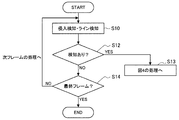
以下では、図3及び図4のフローチャートに基づいて、図1及び図2のブロック図を参照しながら代表画像生成装置1000で行われる処理について説明する。図3は、動画映像から動体を検知する検知フェーズの処理を示すフローチャートであって、動画映像のフレーム毎に行われる。この処理では、禁止エリアへの侵入検知、または指定ラインの通過検知をトリガーとして、図4の適切画像選択フェーズへ移行するかどうかを判断する。先ず、ステップS10では、動体検知を行うとともに、追尾している人物が禁止エリアに侵入したか、あるいは追尾している人物が指定ラインを通過したかを検知する。具体的には、検知部100が、入力された動画映像に対して動体検知を行い、検知指定情報で指定された禁止エリアもしくは指定ラインに対して、人物が侵入、または通過していないかをフレームごとに検知する。
3. 3. Processing Flow Performed by the Representative Image Generator The processing performed by the
ステップS12では、ステップS10の検知の結果、禁止エリアに侵入した人物、または指定ラインを通過した人物が検知された場合は、適切サムネイルを作成するため、ステップS13へ進み、図4の処理へ移行する。一方、禁止エリアに侵入した人物、または指定ラインを通過した人物が検知されなかった場合は、ステップS14へ進み、現フレームが動画映像の検索対象期間の最終フレームであるか否かを判定する。ステップS14で動画映像の最終フレームでない場合は、ステップS10へ戻り、次のフレームについて同様の処理を繰り返す。一方、ステップS14で現フレームが最終フレームの場合は、処理を終了する(end)。 In step S12, when a person who has invaded the prohibited area or a person who has passed the designated line is detected as a result of the detection in step S10, the process proceeds to step S13 and proceeds to the process of FIG. 4 in order to create an appropriate thumbnail. To do. On the other hand, if a person who has invaded the prohibited area or a person who has passed the designated line is not detected, the process proceeds to step S14, and it is determined whether or not the current frame is the final frame of the search target period of the moving image. If it is not the final frame of the moving image in step S14, the process returns to step S10, and the same process is repeated for the next frame. On the other hand, if the current frame is the final frame in step S14, the process ends (end).
ステップS14の判定では、例えば動画映像の検索対象期間が午後5時から午後6時までの動画の場合は、午後6時に撮影されたフレームを最終フレームする。これにより、午後6時以降に撮影されたフレームについては、サムネイル画像作成のための処理は行われない。このように、追跡対象の人物が午後5時から午後6時までの時間帯に監視カメラの前を通過していることが予め明らかな場合は、検索対象期間を午後5時から午後6時までの時間帯に限定することで、サムネイル画像作成のための処理を軽減することができる。 In the determination in step S14, for example, when the search target period of the moving image video is a moving image from 5 pm to 6 pm, the frame shot at 6 pm is the final frame. As a result, the processing for creating thumbnail images is not performed for the frames taken after 6:00 pm. In this way, if it is clear in advance that the person to be tracked is passing in front of the surveillance camera during the time period from 5 pm to 6 pm, the search target period is from 5 pm to 6 pm By limiting to the time zone of, the processing for creating the thumbnail image can be reduced.
なお、図3のフローでは、追尾している人物が禁止エリアに侵入したか、あるいは追尾している人物が指定ラインを通過したかを検知したことをトリガーとして、図4のベストショットフェーズに移行するが、動体検知を行った結果、追尾対象物体が検知されたことをトリガーとして図4の適切画像選択フェーズに移行しても良い。 In the flow of FIG. 3, the transition to the best shot phase of FIG. 4 is triggered by detecting whether the person being tracked has invaded the prohibited area or the person being tracked has passed the designated line. However, the appropriate image selection phase of FIG. 4 may be started with the detection of the object to be tracked as a result of the motion detection as a trigger.
図4は、適切画像選択フェーズの処理を示すフローチャートである。図4の処理もフレーム毎に行われ、検知部100で検知された人物に対して追尾を行い、追尾中の全てのフレームにおいて視認性スコアを算出し、各フレームの画像が追尾する人物の適切画像であるか否か判断する。そして、適切画像と判断された場合は、サムネイル画像を出力する。
FIG. 4 is a flowchart showing the processing of the appropriate image selection phase. The processing of FIG. 4 is also performed for each frame, tracking is performed on the person detected by the
先ず、次のステップS20では、現フレームが最終フレームであるか否かを判定し、最終フレームでない場合はステップS21へ進む。ステップS21では、追尾演算部210が、検知部100で動体検知された人物に対して追尾を行う。具体的には、前フレームまで追尾していた人物を現フレームで探索し、追尾している人物が探索できるとその人物の輪郭の追尾枠を算出し、追尾枠を設定する。
First, in the next step S20, it is determined whether or not the current frame is the final frame, and if it is not the final frame, the process proceeds to step S21. In step S21, the tracking
次のステップS22では、追尾演算部210が、ステップS20の追尾の結果、追尾対象の人物がフレーム内から無くなった(LOSTした)か否かを判定する。そして、追尾が失敗して追尾対象の人物がフレーム内から無くなった場合は、適切画像選択フェーズが終了し、図3の検知フェーズへ再び移行する。追尾対象の人物がフレーム内に存在し、追尾が成功している場合は、ステップS24の視認性確認処理へ進む。
In the next step S22, the tracking
ステップS24では、視認性演算部220が、適性スコアを算出するための複数の視点で視認性確認を実施する。この視認性確認では、複数の重み付け係数を計算する。図5は、図4のステップS24の処理を具体的に示すフローチャートである。
In step S24, the
図5のステップS30では、追尾している物体(人物)の大きさに基づいて重み付け係数(追尾物体のサイズ重み付け係数)W1を算出する。追尾している人物が大きいほど視認性が良いため、重み付け係数W1の値が大きくなる。例えば、追尾している人物が監視カメラに近いほど、人物の大きさが大きくなるため、重み付け係数W1の値が大きくなる。つまり、重み付け係数W1の値が大きいとは、対象人物の画像がより大きいことを示している。 In step S30 of FIG. 5, a weighting coefficient (size weighting coefficient of the tracking object) W1 is calculated based on the size of the object (person) being tracked. The larger the person being tracked, the better the visibility, so the value of the weighting coefficient W1 becomes large. For example, the closer the person being tracked to the surveillance camera, the larger the size of the person, and therefore the larger the value of the weighting coefficient W1. That is, when the value of the weighting coefficient W1 is large, it means that the image of the target person is large.
次のステップS32では、追尾している人物のアスペクト比に基づいて重み付け係数(物体のアスペクト比重み付け係数)W2を算出する。追尾している人物のアスペクト比が一般的な人のアスペクト比(例えば、1:4程度の値)に近い場合は、人物の確からしさが高いため、重み付け係数W2の値が大きくなる。つまり、重み付け係数W2の値が大きいとは、対象人物のアスペクト比が一般的な人のアスペクト比により近いことを示している。次のステップS34では、追尾している人物の方向が監視カメラの正面を向いているかどうかに応じて重み付け係数(追尾方向重み付け係数)W3を算出する。追尾している人物の方向が監視カメラの正面に向いている場合、例えば人物が監視カメラの正面の方向へ向かって歩いている場合は、人物の顔の視認性が良くなるため、重み付け係数W3の値は大きくなる。つまり、重み付け係数W3の値が大きいとは、対象人物がより正面の方向に向かって歩いていることを示している。追尾している人物の方向は、フレーム間で追尾している人物の位置の差分ベクトル(動きベクトル)を求め、この差分ベクトルから求めることができる。 In the next step S32, the weighting coefficient (aspect ratio weighting coefficient of the object ) W2 is calculated based on the aspect ratio of the person being tracked. When the aspect ratio of the person being tracked is close to the aspect ratio of a general person (for example, a value of about 1: 4), the value of the weighting coefficient W2 becomes large because the certainty of the person is high. That is, when the value of the weighting coefficient W2 is large, it means that the aspect ratio of the target person is closer to the aspect ratio of a general person. In the next step S34, the weighting coefficient (tracking direction weighting coefficient) W3 is calculated according to whether or not the direction of the person being tracked is facing the front of the surveillance camera. When the direction of the person being tracked is facing the front of the surveillance camera, for example, when the person is walking toward the front of the surveillance camera, the visibility of the person's face is improved, so the weighting coefficient W3 The value of becomes large. That is, when the value of the weighting coefficient W3 is large, it means that the target person is walking toward the front. The direction of the person being tracked can be obtained from the difference vector (motion vector) of the position of the person being tracked between the frames.
次のステップS36では、追尾している物体の形状が人の形をしているかどうかに応じた重み付け係数(人らしさ重み付け係数)W4を算出する。ここでは、予め準備した辞書データ(人の形のテンプレート)と、画像のエッジ検出等により得られた追尾している物体の形状を比較し、追尾している物体の形状が人の形をしているかどうかを判断する。そして、追尾している物体の形状が人の形に近いほど、重み付け係数W4の値は大きくなる。つまり、重み付け係数W4の値が大きいとは、追尾している物体の形状がより人の形に近いことを示している。 In the next step S36, a weighting coefficient (humanity weighting coefficient) W4 is calculated according to whether or not the shape of the object being tracked is a human shape. Here, the dictionary data (human-shaped template) prepared in advance is compared with the shape of the tracking object obtained by edge detection of the image, and the shape of the tracking object is the human shape. Determine if it is. The closer the shape of the tracking object is to the human shape, the larger the value of the weighting coefficient W4. That is, when the value of the weighting coefficient W4 is large, it means that the shape of the tracking object is closer to the human shape.
次のステップS38では、顔の方向がカメラの方向を向いているかどうかに応じた重み付け係数(顔方向重み付け係数)W5を算出する。具体的には、一般的な顔検出によりフレームの画像から顔を検出し、予め準備した顔の方向に応じたテンプレートと比較することで、顔の方向を判定する。顔の方向がカメラの正面に向いているほど、重み付け係数W5の値は大きくなる。つまり、重み付け係数W5の値が大きいとは、顔の方向がカメラの正面により向いていることを示している。 In the next step S38, a weighting coefficient (face direction weighting coefficient) W5 is calculated according to whether or not the face direction is facing the camera. Specifically, the face direction is determined by detecting the face from the frame image by general face detection and comparing it with a template prepared in advance according to the face direction. The value of the weighting coefficient W5 increases as the direction of the face faces the front of the camera. That is, when the value of the weighting coefficient W5 is large, it means that the direction of the face is closer to the front of the camera.
次のステップS40では、フレーム間の色情報の相関に応じて、追尾中の色の変化が安定しているかどうかを示す重み付け係数(色情報フレーム相関重み付け係数)W6を算出する。例えば、追尾中の人物が日向から日陰に移った場合、車のライトが追尾中の人物に照射された場合など、それまでのフレームと比較して追尾中の色の変化が大きく、色の連続性が低下している場合は、顔の視認性が低下するため、重み付け係数W6の値は小さくなる。また、色情報からフレーム内の人物が一人か複数かを判定し、一人の場合は複数の場合に比べて顔の視認性が良くなるため、重み付け係数W6は大きくなる。つまり、重み付け係数W6の値が大きいとは、顔の視認性がより高いことを示している。 In the next step S40, a weighting coefficient (color information frame correlation weighting coefficient) W6 indicating whether or not the color change during tracking is stable is calculated according to the correlation of the color information between the frames. For example, when the person being tracked moves from the sun to the shade, or when the light of the car illuminates the person being tracked, the color change during tracking is large compared to the previous frame, and the color is continuous. When the sexiness is lowered, the visibility of the face is lowered, so that the value of the weighting coefficient W6 becomes small. Further, it is determined from the color information whether there is one person or a plurality of people in the frame, and in the case of one person, the visibility of the face is improved as compared with the case of a plurality of people, so that the weighting coefficient W6 becomes large. That is, when the value of the weighting coefficient W6 is large, it means that the visibility of the face is higher.
次のステップS42では、追尾している人物の速度に応じた重み付け係数(物体速度重み付け係数)W7を算出する。高速移動より低速移動の方が視認性は良いため、追尾している人物が低速で移動している場合(歩いている場合など)ほど、重み付け係数W7の値は大きくなる。特に夜間はシャッター速度が遅くなるため、人物が高速で移動している場合は、人物の画像にボケやブレが生じやすくなる。このような場合、重み付け係数W7の値は小さくなる。つまり、重み付け係数W7の値が大きいとは、追尾している人物がより低速で移動していることを示している。 In the next step S42, a weighting coefficient (object speed weighting coefficient) W7 according to the speed of the person being tracked is calculated. Since low-speed movement has better visibility than high-speed movement, the value of the weighting coefficient W7 becomes larger when the person being tracked is moving at a lower speed (such as when walking). Especially at night, the shutter speed becomes slow, so when a person is moving at high speed, the image of the person is likely to be blurred or blurred. In such a case, the value of the weighting coefficient W7 becomes small. That is, when the value of the weighting coefficient W7 is large, it means that the person being tracked is moving at a lower speed.
次のステップS44では、追尾物体のノイズ感に応じた重み付け係数(物体S/N重み付け係数)W8を算出する。ここでは、フレームの画像からノイズ(S/N比)を検出し、ノイズが低いほど重み付け係数W8の値を大きくする。例えば、追尾している人物が明るい場所にいる場合はノイズが小さいため、重み付け係数W8の値は大きくなる。つまり、重み付け係数W8の値が大きいとは、画像のノイズがより低いことを示している。 In the next step S44, the weighting coefficient (object S / N weighting coefficient) W8 according to the noise feeling of the tracking object is calculated. Here, noise (S / N ratio) is detected from the image of the frame, and the lower the noise, the larger the value of the weighting coefficient W8. For example, when the person being tracked is in a bright place, the noise is small, so the value of the weighting coefficient W8 becomes large. That is, when the value of the weighting coefficient W8 is large, it means that the noise of the image is lower.
次のステップS46では、追尾している人物の輝度値に応じた重み付け係数(物体輝度重み付け係数)W9を算出する。例えば、輝度値が低い場合は、追尾している人物の顔の判別が難しくなるため、重み付け係数W9の値は小さくなる。また、輝度値が高すぎて飽和している場合も、追尾している人物の顔の判別が難しくなるため、重み付け係数W9の値は小さくなる。すなわち、黒潰れ映像、または白とび映像の場合は、重み付け係数W9の値は小さくなる。つまり、重み付け係数W9の値が大きいとは、顔の判別がより容易であることを示している。なお、ステップS30〜S46に示した処理は一例であり、他にも視認性を判断する処理があれば、その処理に応じた重み付け係数Wnを追加しても良い(ステップS48)。 In the next step S46, a weighting coefficient (object brightness weighting coefficient) W9 corresponding to the brightness value of the person being tracked is calculated. For example, when the brightness value is low, it becomes difficult to discriminate the face of the person being tracked, so that the value of the weighting coefficient W9 becomes small. Further, when the brightness value is too high and saturated, it becomes difficult to discriminate the face of the person being tracked, so that the value of the weighting coefficient W9 becomes small. That is, in the case of a black crushed image or an overexposed image, the value of the weighting coefficient W9 becomes small. That is, when the value of the weighting coefficient W9 is large, it means that the face can be easily identified. The processes shown in steps S30 to S46 are examples, and if there is another process for determining visibility, a weighting coefficient Wn corresponding to the process may be added (step S48).
図5の処理によれば、動体検知した追尾対象の人物の視認性が高いほど、各重み付け係数W1〜W9の値が大きくなる。なお、ステップS30〜S46の処理は、動体検知された追尾対象に設定された追尾枠内の画像について行われるが、フレームの全体画像について行っても良い。 According to the process of FIG. 5, the higher the visibility of the person to be tracked when the moving object is detected, the larger the values of the weighting coefficients W1 to W9. The processing of steps S30 to S46 is performed on the image in the tracking frame set as the tracking target for which the moving object is detected, but it may be performed on the entire image of the frame.
以上のようにして図4のステップS24で視認性確認を行うと、次のステップS26へ進む。ステップS26では、適性演算部230が、図5の各ステップで求めた重み付け係数W1〜W9の要素をすべて加味して現フレームの適性スコアを算出する。そして、算出した適性スコアを今までのフレームの適性スコアの最大値と比較して、現フレームのスコア値の方が高い場合は、現フレームが適切画像と判定する。つまり、大きく映っている、アスペクト比が一般的な人のアスペクト比に近い、正面を向いている、追尾している物体の形状が人の形に近い、顔の方向がカメラの正面に向いている、顔の視認性が高い、追尾している人物が低速で移動している、画像のノイズが低い、顔の判別が容易である等を考慮して、視認性が高い、また、適切な画像と判断される画像を適切画像と判定する。
When the visibility is confirmed in step S24 of FIG. 4 as described above, the process proceeds to the next step S26. In step S26, the
具体的には、図5の各ステップで求めた現フレームの重み付け係数W1〜W9の合計と、前回までの各フレームで算出した重み付け係数W1〜W9の合計の最大値とを比較し、現フレームの重み付け係数W1〜W9の合計が前回までの各フレームで算出した重み付け係数W1〜W9の合計の最大値よりも大きい場合は現フレームが適切画像であると判定し、ステップS28へ進む。 Specifically, the total of the weighting coefficients W1 to W9 of the current frame obtained in each step of FIG. 5 is compared with the maximum value of the total of the weighting coefficients W1 to W9 calculated in each frame up to the previous time, and the current frame is compared. If the total of the weighting coefficients W1 to W9 is larger than the maximum value of the total of the weighting coefficients W1 to W9 calculated in each frame up to the previous time, it is determined that the current frame is an appropriate image, and the process proceeds to step S28.
ステップS28では、サムネイル作成部240が、現フレームの画像から、追尾している人物のサムネイル画像を作成する。この際、追尾演算部210で算出された追尾枠を利用してサムネイル画像を作成する。そして、前回までのフレームで作成されたサムネイル画像(サムネイル候補画像)と置き換えることでサムネイル画像を更新する。ステップS28の後は次のフレームの処理を行うため、ステップS20へ戻る。
In step S28, the
また、ステップS26で現フレームが適切画像ではないと判定された場合は、サムネイル画像の作成を行うことなく、次のフレームの処理を行うため、ステップS20へ戻る。 If it is determined in step S26 that the current frame is not an appropriate image, the process returns to step S20 in order to process the next frame without creating a thumbnail image.
なお、ステップS26の判定において、現フレームのスコアが今までのフレームのベストショットスコアの最大値に達していなくても、現フレームの適性スコアが予め設定した所定のしきい値よりも大きい場合は、ステップS28へ進んでサムネイル画像作成処理を行っても良い。 In the determination of step S26, even if the score of the current frame does not reach the maximum value of the best shot score of the frame so far, if the aptitude score of the current frame is larger than a predetermined threshold value set in advance. , You may proceed to step S28 to perform the thumbnail image creation process.
以上のように、図3と図4の処理を繰り返し行うことで、サムネイル画像を最も視認性の良い画像に更新することができる。イベント検知時の対象人物に対応する画像として、検知時とは異なる時間、異なるフレームの画像も含めて、視認性を考慮して、適切な画像に更新することができる。
なお、上述した例では、適性スコアの最大値が更新される度にサムネイル画像を作成して更新しているが、最終フレームまではサムネイル画像を作成することなく各フレームの適性スコア値を算出し、最終フレームのスコア値を算出した後に、最大値を記録したフレームからサムネイル画像を作成しても良い。
As described above, by repeating the processes of FIGS. 3 and 4, the thumbnail image can be updated to the image with the best visibility. As an image corresponding to the target person at the time of event detection, it is possible to update the image to an appropriate image in consideration of visibility, including an image of a different frame at a time different from that at the time of detection.
In the above example, a thumbnail image is created and updated every time the maximum value of the aptitude score is updated, but the aptitude score value of each frame is calculated without creating a thumbnail image until the final frame. , After calculating the score value of the final frame, a thumbnail image may be created from the frame in which the maximum value is recorded.
4.通常手法と本実施形態とでサムネイル画像出力の効果の比較した例
図6は、指定ラインの通過を検知したケースにおいて、通常手法のサムネイル画像出力と本実施形態のサムネイル画像出力とで効果を比較した例を示す模式図である。図6において、画像300は、動画映像のフレームに破線で示すような指定ライン302を設定した状態を示している。指定ライン302を設定した場合は、指定ライン302を人物が通過したことが検知されるとアラートが出される。通常手法では、画像310に示すように、指定ライン302を人物が通過した時点で、画像310の追尾枠312で囲まれた領域が切り出されてサムネイル画像が出力される。この場合、指定ライン302を人物が通過した時点でのサムネイル画像は、人物が遠くに写っているため、顔が小さく、顔から人物像を特定することは難しい。
4. Example of comparing the effect of thumbnail image output between the normal method and the present embodiment FIG. 6 compares the effect between the thumbnail image output of the normal method and the thumbnail image output of the present embodiment in the case where the passage of the designated line is detected. It is a schematic diagram which shows the example. In FIG. 6, the
一方、本実施形態によれば、指定ライン302を人物が通過したことをトリガーとして、対象物体の追尾を開始する。そして、各フレームで適性スコアを算出して、最もスコアの高いフレームからサムネイル画像を出力する。この結果、画像320に示すように、追尾枠322で囲まれた領域が切り出されてサムネイル画像が出力される。これにより、人物の全身が大きく映り、人物が監視カメラの正面を向いた視認性が良いシーンが選択され、サムネイル画像として出力されることになる。従って、人物を観察する際に、観察に適した最も状態が良いシーンのサムネイル画像を出力することが可能になる。
On the other hand, according to the present embodiment, the tracking of the target object is started by triggering the passage of the designated
5.監視カメラの構成例
図7は、代表画像生成装置1000を備えた監視カメラ2000の構成を示す模式図である。監視カメラ2000は、撮像部400と、代表画像生成装置1000と、表示部410と、を有して構成される。撮像部400は、CMOSセンサ等の撮像素子と、被写体像を撮像素子の撮像面に結像させる光学系を有して構成され、撮像素子で光電変換されることによって得られた画像データ(動画映像)は代表画像生成装置1000の検知部100へ入力される。監視カメラ(ネットワークカメラとも呼ばれる)は、ネットワーク接続が可能で、ネットワークを介して画像伝送を行うことができる。
5. Configuration example of the surveillance camera FIG. 7 is a schematic diagram showing the configuration of the
表示部410は、液晶表示ディスプレイ等から構成され、代表画像生成装置1000の適切サムネイル作成部200が作成したサムネイル画像を表示する。表示部410は、監視カメラ2000を管理する管理装置(監視カメラとは別体)に設けられていても良く、この場合、サムネイル画像が管理装置に送られて管理装置の表示部410に表示される。また、適切サムネイル作成部200は、監視カメラ2000を管理する管理装置(監視カメラとは別体)に設けられていても良い。その場合、カメラからは画像が管理装置に送られる場合(ケースA)と、検知結果が管理装置に送られる場合(ケースB)がある。ケースAの場合は、管理装置において、検知処理、適切サムネイル選択処理等々が行われる。ケースBの場合は、管理装置において、適切サムネイル選択処理等が行われる。
The
図8は、代表画像生成装置1000が取得したラインクロッシング設定画面、ライン通過シーン確認画面、適切画像確認画面を事後的に取得する様子を示す模式図である。上述したように、代表画像生成装置1000は、記憶部250、表示処理部260、操作入力部270を有している。代表画像生成装置1000は、取得した適切サムネイル画像を記憶部250に保存する。また、代表画像生成装置1000は、適切サムネイル画像を作成した人物に関し、ラインクロッシング設定画面、ライン通過シーン確認画面、適切サムネイル画像確認画面を記憶部250に保存する。表示処理部260は、図8に示すように、適切サムネイル画像の一覧、ラインクロッシング設定画面、ライン通過シーン確認画面、適正画像確認画面を表示するための処理を行う。
FIG. 8 is a schematic view showing how the line crossing setting screen, the line passing scene confirmation screen, and the appropriate image confirmation screen acquired by the
ラインクロッシング設定画面には、適切サムネイル画像毎に、検知指定情報で指定された指定ラインが表示される。なお、ユーザは、操作入力部270を操作することで、指定ラインの位置を自由に変更することができ、指定ラインの変更に伴って検知指定情報が変更される。ライン通過シーン確認画面には、図3のステップS10において、追尾している人物が指定ラインを通過した際のシーンが表示される。適切画像確認画面には、適切サムネイル画像を取得した際の全体画像が表示される。あるいは、全体画像ではなく、適切サムネイル画像等の画像の一部を表示しても良い。各適切サムネイル画像に対応するラインクロッシング設定画面、ライン通過シーン確認画面、適切画像確認画面は、各適切サムネイル画像と紐付けて記憶部250に保存されている。
On the line crossing setting screen, the designated line specified by the detection designated information is displayed for each appropriate thumbnail image. The user can freely change the position of the designated line by operating the
ユーザは、操作入力部270により操作情報を入力することで、適切サムネイル画像の一覧の中から特定の適切サムネイル画像を指定することができる。具体的には、ユーザは、例えばマウスを操作して特定の適切サムネイル画像をクリックすることで、操作入力部270に操作情報を入力することができ、特定の適切サムネイル画像を指定することができる。ユーザが特定の適切サムネイル画像を指定すると、図8に示すように、指定された適切サムネイル画像に対応するラインクロッシング設定画面、ライン通過シーン確認画面、及び適切画像確認画面が表示される。これにより、ユーザは、追尾している人物が指定ラインを通過した時点の画像と、適切サムネイル画像が生成された時点の画像の双方を確認することが可能となる。また、指定ラインの位置についてもラインクロッシング設定画面から確認することが可能となる。
The user can specify a specific appropriate thumbnail image from the list of appropriate thumbnail images by inputting the operation information by the
本実施形態によれば、特定のトリガーがかかった瞬間(侵入検知等)の映像を切り出してサムネイル画像を出力するのではなく、トリガーがかかった状態からその対象物体を毎フレーム追尾し、追尾中のフレームごとにスコアを計算し、最も良いスコアとなったフレームの画像から追尾している物体のサムネイル画像を作成する。従って、最も視認性が良好なサムネイル画像を出力することができ、サムネイル画像から人物等を確実に特定することが可能となる。
なお、トリガーとして侵入検知を例に説明を行ったが、侵入検知以外でも良い。例えば、所定の条件を満たす物体の検出等のイベントの検出をトリガーとしても良い。また、あるいは、赤外線センサなどの外部のセンサから所定の信号の入力、などをトリガーとしても良い。
According to this embodiment, instead of cutting out the image at the moment when a specific trigger is applied (intrusion detection, etc.) and outputting the thumbnail image, the target object is tracked every frame from the state where the trigger is applied, and the tracking is in progress. The score is calculated for each frame of, and a thumbnail image of the tracking object is created from the image of the frame with the best score. Therefore, it is possible to output a thumbnail image having the best visibility, and it is possible to reliably identify a person or the like from the thumbnail image.
Although the explanation has been given using intrusion detection as an example as a trigger, it may be other than intrusion detection. For example, the detection of an event such as the detection of an object satisfying a predetermined condition may be used as a trigger. Alternatively, a predetermined signal may be input from an external sensor such as an infrared sensor as a trigger.
以上、添付図面を参照しながら本開示の好適な実施形態について詳細に説明したが、本開示の技術的範囲はかかる例に限定されない。本開示の技術分野における通常の知識を有する者であれば、特許請求の範囲に記載された技術的思想の範疇内において、各種の変更例または修正例に想到し得ることは明らかであり、これらについても、当然に本開示の技術的範囲に属するものと了解される。 Although the preferred embodiments of the present disclosure have been described in detail with reference to the accompanying drawings, the technical scope of the present disclosure is not limited to such examples. It is clear that a person having ordinary knowledge in the technical field of the present disclosure can come up with various modifications or modifications within the scope of the technical ideas described in the claims. Of course, it is understood that the above also belongs to the technical scope of the present disclosure.
また、本明細書に記載された効果は、あくまで説明的または例示的なものであって限定的ではない。つまり、本開示に係る技術は、上記の効果とともに、または上記の効果に代えて、本明細書の記載から当業者には明らかな他の効果を奏しうる。 In addition, the effects described herein are merely explanatory or exemplary and are not limited. That is, the techniques according to the present disclosure may exhibit other effects apparent to those skilled in the art from the description herein, in addition to or in place of the above effects.
なお、以下のような構成も本開示の技術的範囲に属する。
(1) 動画映像を取得し、動体検知により前記動画映像の中から対象物体を検知する検
知部と、
前記検知部が前記対象物体を検知した後、前記動画映像中で移動する前記対象物体を追
尾する追尾部と、
前記検知部が前記対象物体を検知した後、前記追尾部が追尾した前記対象物体を示す代
表画像を作成する代表画像作成部と、
を備える、代表画像生成装置。
(2) 前記追尾部が前記対象物体を追尾している間、前記対象物体の視認性を演算する
視認性演算部を備え、
前記代表画像作成部は、前記視認性演算部が前記対象物体の視認性を演算した結果に基
づいて前記代表画像を作成する、前記(1)に記載の代表画像生成装置。
(3) 前記視認性演算部は、前記動画映像のフレーム毎に前記対象物体の視認性を演算
し、
前記代表画像作成部は、前記対象物体の視認性が最も高いフレームの画像から前記代表
画像を作成する、前記(2)に記載の代表画像生成装置。
(4) 前記視認性演算部は、前記動画映像のフレーム毎に前記対象物体の視認性を演算
し、
前記代表画像作成部は、前記対象物体の視認性が所定のしきい値以上のフレームの画像
から前記代表画像を作成する、前記(2)又は(3)に記載の代表画像生成装置。
(5) 前記視認性演算部は、前記動画映像のフレーム毎に前記対象物体の視認性を示す
複数のファクターのそれぞれについての重み付け係数を算出し、
前記重み付け係数に基づいて、前記対象物体の視認性が高いフレームの画像のスコアを
演算するベストショット演算部を備え、
前記代表画像作成部は、前記ベストショット演算部の算出結果に基づいて、前記対象物
体の視認性が高いフレームの画像から前記代表画像を作成する、前記(2)〜(4)のい
ずれかに記載の代表画像生成装置。
(6) 前記対象物体の視認性が高いほど前記重み付け係数の値は大きくなり、
前記代表画像作成部は、前記重み付け係数の合計値が最も大きいフレームの画像から前
記代表画像を作成する、前記(5)に記載の代表画像生成装置。
(7) 前記対象物体の視認性が高いほど前記重み付け係数の値は大きくなり、
前記代表画像作成部は、前記重み付け係数の合計値が所定のしきい値以上のフレームの
画像から前記代表画像を作成する、前記(5)に記載の代表画像生成装置。
(8) 前記代表画像作成部は、現フレームの前記重み付け係数の合計値が前回までのフ
レームの前記重み付け係数の合計値よりも大きい場合に前記代表画像を作成し、前回まで
のフレームで作成された前記代表画像を更新する、前記(6)に記載の代表画像生成装置
。
(9) 前記対象物体は人物であり、
前記複数のファクターは、人物の大きさ、人物のアスペクト比、人物の追尾方向、人物
の人らしさ、人物の顔の方向、人物の色情報、人物の移動速度、人物の画像に含まれるノ
イズ、及び人物の輝度のいずれかを含む、前記(5)〜(8)のいずれかに記載の代表画
像生成装置。
(10) 前記検知部は、前記動画映像の中から所定の条件を満たす前記対象物体を検知
し、
前記所定の条件は、前記対象物体が所定の禁止エリアに侵入したこと、又は前記対象物
体が所定の指定ラインを通過したことである、前記(1)〜(9)のいずれかに記載の代
表画像生成装置。
(11) 前記指定ラインを設定するための第1の画像、前記対象物体が前記指定ラインを通過した際に取得された第2の画像、又は前記代表画像を作成した際に取得された第3の画像を保存する記憶部を備える、前記(10)に記載の代表画像生成装置。
(12) ユーザの操作入力に基づいて指定された前記代表画像に対応する前記第1の画像、前記第2の画像及び前記第3の画像の少なくとも1つを表示するための処理を行う表示処理部を備える、前記(11)に記載の代表画像生成装置。
(13) 動画映像を取得し、動体検知により前記動画映像の中から対象物体を検知する
ことと、
前記対象物体を検知した後、前記動画映像中で移動する前記対象物体を追尾することと
、
前記対象物体を検知した後、追尾した前記対象物体を示す代表画像を作成することと、
を備える、代表画像生成方法。
(14) 動画映像を取得し、動体検知により前記動画映像の中から対象物体を検知する
手段、
前記対象物体を検知した後、前記動画映像中で移動する前記対象物体を追尾する手段、
前記対象物体を検知した後、追尾した前記対象物体を示す代表画像を作成する手段、
としてコンピュータを機能させるためのプログラム。
The following configurations also belong to the technical scope of the present disclosure.
(1) A detection unit that acquires a moving image and detects a target object from the moving object by detecting a moving object.
After the detection unit detects the target object, the tracking unit that tracks the target object that moves in the moving image and the like,
A representative image creation unit that creates a representative image showing the target object tracked by the tracking unit after the detection unit detects the target object.
A representative image generator.
(2) A visibility calculation unit for calculating the visibility of the target object while the tracking unit is tracking the target object is provided.
The representative image generation device according to (1), wherein the representative image creating unit creates the representative image based on the result of the visibility calculation unit calculating the visibility of the target object.
(3) The visibility calculation unit calculates the visibility of the target object for each frame of the moving image image.
The representative image generation device according to (2), wherein the representative image creating unit creates the representative image from an image of a frame having the highest visibility of the target object.
(4) The visibility calculation unit calculates the visibility of the target object for each frame of the moving image image.
The representative image generation device according to (2) or (3), wherein the representative image creating unit creates the representative image from an image of a frame in which the visibility of the target object is equal to or higher than a predetermined threshold value.
(5) The visibility calculation unit calculates a weighting coefficient for each of a plurality of factors indicating the visibility of the target object for each frame of the moving image image.
A best shot calculation unit for calculating the score of an image of a frame having high visibility of the target object based on the weighting coefficient is provided.
The representative image creating unit creates the representative image from an image of a frame having high visibility of the target object based on the calculation result of the best shot calculation unit, according to any one of (2) to (4). The representative image generator described.
(6) The higher the visibility of the target object, the larger the value of the weighting coefficient.
The representative image generation device according to (5), wherein the representative image creating unit creates the representative image from an image of a frame having the largest total value of the weighting coefficients.
(7) The higher the visibility of the target object, the larger the value of the weighting coefficient.
The representative image generation device according to (5), wherein the representative image creating unit creates the representative image from an image of a frame in which the total value of the weighting coefficients is equal to or greater than a predetermined threshold value.
(8) The representative image creating unit creates the representative image when the total value of the weighting coefficients of the current frame is larger than the total value of the weighting coefficients of the frames up to the previous time, and is created in the frames up to the previous time. The representative image generator according to (6) above, which updates the representative image.
(9) The target object is a person
The plurality of factors include the size of the person, the aspect ratio of the person, the tracking direction of the person, the personality of the person, the direction of the face of the person, the color information of the person, the moving speed of the person, and the noise contained in the image of the person. The representative image generator according to any one of (5) to (8) above, which includes any of the brightness of the person and the person.
(10) The detection unit detects the target object satisfying a predetermined condition from the moving image and the like.
The representative according to any one of (1) to (9) above, wherein the predetermined condition is that the target object has entered a predetermined prohibited area or that the target object has passed a predetermined designated line. Image generator.
(11) A first image for setting the designated line, a second image acquired when the target object passes the designated line, or a third image acquired when the representative image is created. The representative image generation device according to (10) above, which includes a storage unit for storing the image of.
(12) Display processing for displaying at least one of the first image, the second image, and the third image corresponding to the representative image designated based on the user's operation input. The representative image generation device according to (11) above, which comprises a unit.
(13) Acquiring a moving image and detecting a target object from the moving object by detecting a moving object.
After detecting the target object, tracking the target object moving in the moving image is
After detecting the target object, creating a representative image showing the tracked target object, and
A representative image generation method.
(14) A means for acquiring a moving image and detecting a target object from the moving object by detecting a moving object.
A means for tracking the target object moving in the moving image after detecting the target object,
A means for creating a representative image showing the tracked target object after detecting the target object,
A program to make your computer work as.
100 検知部
210 追尾演算部
220 視認性演算部
230 適性演算部
250 記憶部
260 表示処理部
240 サムネイル作成部
1000 代表画像生成装置
100
Claims (14)
前記検知部が前記対象物体を検知した後、前記動画映像中で移動する前記対象物体を追尾する追尾部と、
前記検知部が前記対象物体を検知した後、前記追尾部が追尾した前記対象物体を示す代表画像を作成する代表画像作成部と、
を備え、
前記代表画像作成部は、
予め指定された時間帯において取得された前記動画映像に基づき前記代表画像を生成し、
前記検知部は、
前記時間帯の最終フレームで前記対象物体の前記検知を終了させる、
代表画像生成装置。 A detection unit that acquires a moving image and detects a target object from the moving object by detecting a moving object.
After the detection unit detects the target object, the tracking unit that tracks the target object that moves in the moving image and the like,
A representative image creation unit that creates a representative image showing the target object tracked by the tracking unit after the detection unit detects the target object.
Equipped with a,
The representative image creation unit
The representative image is generated based on the moving image acquired in a predetermined time zone, and the representative image is generated.
The detector is
Wherein the final frame of the time zone Ru to terminate the detection of the target object,
Representative image generator.
前記代表画像作成部は、前記視認性演算部が前記対象物体の視認性を演算した結果に基づいて前記代表画像を作成する、請求項1に記載の代表画像生成装置。 A visibility calculation unit that calculates the visibility of the target object while the tracking unit is tracking the target object is provided.
The representative image generation device according to claim 1, wherein the representative image creating unit creates the representative image based on the result of the visibility calculation unit calculating the visibility of the target object.
前記代表画像作成部は、前記対象物体の視認性が最も高いフレームの画像から前記代表画像を作成する、請求項2に記載の代表画像生成装置。 The visibility calculation unit calculates the visibility of the target object for each frame of the moving image image, and then calculates the visibility of the target object.
The representative image generation device according to claim 2, wherein the representative image creating unit creates the representative image from an image of a frame having the highest visibility of the target object.
前記代表画像作成部は、前記対象物体の視認性が所定のしきい値以上のフレームの画像から前記代表画像を作成する、請求項2又は3に記載の代表画像生成装置。 The visibility calculation unit calculates the visibility of the target object for each frame of the moving image image, and then calculates the visibility of the target object.
The representative image generation device according to claim 2 or 3, wherein the representative image creating unit creates the representative image from an image of a frame in which the visibility of the target object is equal to or higher than a predetermined threshold value.
前記重み付け係数に基づいて、前記対象物体の視認性が高いフレームの画像のスコアを演算する適性演算部を備え、
前記代表画像作成部は、前記適性演算部の算出結果に基づいて、前記対象物体の視認性が高いフレームの画像から前記代表画像を作成する、請求項2〜4のいずれか1項に記載の代表画像生成装置。 The visibility calculation unit calculates a weighting coefficient for each of a plurality of factors indicating the visibility of the target object for each frame of the moving image image.
An aptitude calculation unit for calculating the score of an image of a frame having high visibility of the target object based on the weighting coefficient is provided.
The representative image creating unit according to any one of claims 2 to 4, wherein the representative image creating unit creates the representative image from an image of a frame having high visibility of the target object based on the calculation result of the aptitude calculation unit. Representative image generator.
前記代表画像作成部は、前記重み付け係数の合計値が最も大きいフレームの画像から前記代表画像を作成する、請求項5に記載の代表画像生成装置。 The higher the visibility of the target object, the larger the value of the weighting coefficient.
The representative image generation device according to claim 5, wherein the representative image creating unit creates the representative image from an image of a frame having the largest total value of the weighting coefficients.
前記代表画像作成部は、前記重み付け係数の合計値が所定のしきい値以上のフレームの画像から前記代表画像を作成する、請求項5に記載の代表画像生成装置。 The higher the visibility of the target object, the larger the value of the weighting coefficient.
The representative image generation device according to claim 5, wherein the representative image creating unit creates the representative image from an image of a frame in which the total value of the weighting coefficients is equal to or greater than a predetermined threshold value.
前記複数のファクターは、人物の大きさ、人物のアスペクト比、人物の追尾方向、人物の人らしさ、人物の顔の方向、人物の色情報、人物の移動速度、人物の画像に含まれるノイズ、及び人物の輝度のいずれかを含む、請求項5〜8のいずれか1項に記載の代表画像生成装置。 The target object is a person
The plurality of factors include the size of the person, the aspect ratio of the person, the tracking direction of the person, the personality of the person, the direction of the face of the person, the color information of the person, the moving speed of the person, and the noise contained in the image of the person. The representative image generator according to any one of claims 5 to 8, further comprising any one of the brightness of the person and the person.
前記所定の条件は、前記対象物体が所定の禁止エリアに侵入したこと、又は前記対象物体が所定の指定ラインを通過したことである、請求項1〜9のいずれか1項に記載の代表画像生成装置。 The detection unit detects the target object satisfying a predetermined condition from the moving image and the like, and detects the target object.
The representative image according to any one of claims 1 to 9, wherein the predetermined condition is that the target object has entered a predetermined prohibited area or that the target object has passed a predetermined designated line. Generator.
前記対象物体を検知した後、前記動画映像中で移動する前記対象物体を追尾することと、
前記対象物体を検知した後、追尾した前記対象物体を示す代表画像を作成することと、
を備え、
前記代表画像を作成することは、
予め指定された時間帯において取得された前記動画映像に基づき前記代表画像を生成し、
前記検知することは、
前記時間帯の最終フレームで前記対象物体の前記検知を終了させる、
代表画像生成方法。 Acquiring a moving image and detecting a target object from the moving object by detecting a moving object,
After detecting the target object, tracking the target object moving in the moving image is
After detecting the target object, creating a representative image showing the tracked target object, and
Equipped with a,
Creating the representative image is
The representative image is generated based on the moving image acquired in a predetermined time zone, and the representative image is generated.
The detection is
Wherein the final frame of the time zone Ru to terminate the detection of the target object,
Representative image generation method.
前記対象物体を検知した後、前記動画映像中で移動する前記対象物体を追尾する手段、
前記対象物体を検知した後、追尾した前記対象物体を示す代表画像を作成する手段、
としてコンピュータを機能させ、
前記代表画像を作成する手段は、
予め指定された時間帯において取得された前記動画映像に基づき前記代表画像を生成し、
前記検知する手段は、
前記時間帯の最終フレームで前記対象物体の前記検知を終了させるためのプログラム。 A means for acquiring a moving image and detecting a target object from the moving object by detecting a moving object.
A means for tracking the target object moving in the moving image after detecting the target object,
A means for creating a representative image showing the tracked target object after detecting the target object,
Cause the computer to function as,
The means for creating the representative image is
The representative image is generated based on the moving image acquired in a predetermined time zone, and the representative image is generated.
The detection means
The target object the program order to terminate the detection of the final frame of the time zone.
Priority Applications (3)
| Application Number | Priority Date | Filing Date | Title |
|---|---|---|---|
| PCT/JP2016/003787 WO2017051499A1 (en) | 2015-09-25 | 2016-08-18 | Representative image generation device, representative image generation method, and program |
| US15/758,226 US10740623B2 (en) | 2015-09-25 | 2016-08-18 | Representative image generation device and representative image generation method |
| US16/899,795 US20200311438A1 (en) | 2015-09-25 | 2020-06-12 | Representative image generation device and representative image generation method |
Applications Claiming Priority (2)
| Application Number | Priority Date | Filing Date | Title |
|---|---|---|---|
| JP2015188071 | 2015-09-25 | ||
| JP2015188071 | 2015-09-25 |
Publications (3)
| Publication Number | Publication Date |
|---|---|
| JP2017063402A JP2017063402A (en) | 2017-03-30 |
| JP2017063402A5 JP2017063402A5 (en) | 2019-08-22 |
| JP6772609B2 true JP6772609B2 (en) | 2020-10-21 |
Family
ID=58429406
Family Applications (1)
| Application Number | Title | Priority Date | Filing Date |
|---|---|---|---|
| JP2016139778A Active JP6772609B2 (en) | 2015-09-25 | 2016-07-14 | Representative image generator, representative image generation method and program |
Country Status (2)
| Country | Link |
|---|---|
| US (2) | US10740623B2 (en) |
| JP (1) | JP6772609B2 (en) |
Families Citing this family (2)
| Publication number | Priority date | Publication date | Assignee | Title |
|---|---|---|---|---|
| WO2019022209A1 (en) * | 2017-07-26 | 2019-01-31 | 旭化成株式会社 | Monitoring system and monitoring method |
| JP7086552B2 (en) * | 2017-09-22 | 2022-06-20 | キヤノン株式会社 | Information processing equipment, imaging equipment, information processing methods and programs |
Family Cites Families (11)
| Publication number | Priority date | Publication date | Assignee | Title |
|---|---|---|---|---|
| US6696945B1 (en) | 2001-10-09 | 2004-02-24 | Diamondback Vision, Inc. | Video tripwire |
| US7227893B1 (en) | 2002-08-22 | 2007-06-05 | Xlabs Holdings, Llc | Application-specific object-based segmentation and recognition system |
| JP4614653B2 (en) * | 2003-12-12 | 2011-01-19 | ソニー株式会社 | Monitoring device |
| JP2005227957A (en) * | 2004-02-12 | 2005-08-25 | Mitsubishi Electric Corp | Optimal face image recording device and optimal face image recording method |
| US20070250898A1 (en) * | 2006-03-28 | 2007-10-25 | Object Video, Inc. | Automatic extraction of secondary video streams |
| EP2100453B1 (en) | 2006-12-18 | 2013-07-03 | FUJIFILM Corporation | Monitoring system, monitoring method and program |
| JP4387415B2 (en) * | 2007-01-22 | 2009-12-16 | セイコープレシジョン株式会社 | VIDEO INFORMATION SYSTEM, OPERATION METHOD, AND PROGRAM |
| JP4996404B2 (en) * | 2007-09-20 | 2012-08-08 | 技研トラステム株式会社 | Human behavior search device |
| JP5393190B2 (en) * | 2009-02-17 | 2014-01-22 | キヤノン株式会社 | Display control device, display control device control method, program, and recording medium |
| JP5355446B2 (en) * | 2010-02-19 | 2013-11-27 | 株式会社東芝 | Moving object tracking system and moving object tracking method |
| MY167508A (en) | 2011-04-14 | 2018-09-04 | Mimos Berhad | Intrusion detection system for determining object position |
-
2016
- 2016-07-14 JP JP2016139778A patent/JP6772609B2/en active Active
- 2016-08-18 US US15/758,226 patent/US10740623B2/en active Active
-
2020
- 2020-06-12 US US16/899,795 patent/US20200311438A1/en not_active Abandoned
Also Published As
| Publication number | Publication date |
|---|---|
| JP2017063402A (en) | 2017-03-30 |
| US20180260632A1 (en) | 2018-09-13 |
| US20200311438A1 (en) | 2020-10-01 |
| US10740623B2 (en) | 2020-08-11 |
Similar Documents
| Publication | Publication Date | Title |
|---|---|---|
| EP2467805B1 (en) | Method and system for image analysis | |
| US7280673B2 (en) | System and method for searching for changes in surveillance video | |
| JP5227911B2 (en) | Surveillance video retrieval device and surveillance system | |
| KR101064573B1 (en) | System for tracking a moving object, by using particle filtering | |
| WO2014171258A1 (en) | Information processing system, information processing method, and program | |
| US9875408B2 (en) | Setting apparatus, output method, and non-transitory computer-readable storage medium | |
| JP2009212637A (en) | Imaging device | |
| US20200374491A1 (en) | Forensic video exploitation and analysis tools | |
| JP2008026974A (en) | Person tracking device | |
| JP2019200715A (en) | Image processing apparatus, image processing method, and program | |
| JP6772609B2 (en) | Representative image generator, representative image generation method and program | |
| JP4699056B2 (en) | Automatic tracking device and automatic tracking method | |
| KR101648786B1 (en) | Method of object recognition | |
| JP2017063402A5 (en) | ||
| US11151730B2 (en) | System and method for tracking moving objects | |
| WO2017051499A1 (en) | Representative image generation device, representative image generation method, and program | |
| CN110826387A (en) | Detection apparatus, control method thereof, and computer-readable recording medium | |
| JP2014135683A (en) | Imaging control apparatus, imaging control method, and imaging control program | |
| JP7332047B2 (en) | Tracking Devices, Tracking Systems, Tracking Methods, and Programs | |
| JP2020067905A (en) | Detecting device and control method thereof | |
| KR20220117981A (en) | CCTV events auto recordoing and storage system using eye tracking | |
| CN115086619A (en) | Video data transmission method and device, camera and storage medium | |
| JP2020024669A (en) | Detection device and control method thereof | |
| JP2011123562A (en) | Image processing apparatus, image processing method, and program |
Legal Events
| Date | Code | Title | Description |
|---|---|---|---|
| RD04 | Notification of resignation of power of attorney |
Free format text: JAPANESE INTERMEDIATE CODE: A7424 Effective date: 20190208 |
|
| RD03 | Notification of appointment of power of attorney |
Free format text: JAPANESE INTERMEDIATE CODE: A7423 Effective date: 20190214 |
|
| RD04 | Notification of resignation of power of attorney |
Free format text: JAPANESE INTERMEDIATE CODE: A7424 Effective date: 20190222 |
|
| RD02 | Notification of acceptance of power of attorney |
Free format text: JAPANESE INTERMEDIATE CODE: A7422 Effective date: 20190515 |
|
| RD04 | Notification of resignation of power of attorney |
Free format text: JAPANESE INTERMEDIATE CODE: A7424 Effective date: 20190522 |
|
| A521 | Written amendment |
Free format text: JAPANESE INTERMEDIATE CODE: A523 Effective date: 20190709 |
|
| A621 | Written request for application examination |
Free format text: JAPANESE INTERMEDIATE CODE: A621 Effective date: 20190709 |
|
| A977 | Report on retrieval |
Free format text: JAPANESE INTERMEDIATE CODE: A971007 Effective date: 20200423 |
|
| A131 | Notification of reasons for refusal |
Free format text: JAPANESE INTERMEDIATE CODE: A131 Effective date: 20200519 |
|
| A521 | Written amendment |
Free format text: JAPANESE INTERMEDIATE CODE: A523 Effective date: 20200710 |
|
| TRDD | Decision of grant or rejection written | ||
| A01 | Written decision to grant a patent or to grant a registration (utility model) |
Free format text: JAPANESE INTERMEDIATE CODE: A01 Effective date: 20200901 |
|
| A61 | First payment of annual fees (during grant procedure) |
Free format text: JAPANESE INTERMEDIATE CODE: A61 Effective date: 20200914 |
|
| R151 | Written notification of patent or utility model registration |
Ref document number: 6772609 Country of ref document: JP Free format text: JAPANESE INTERMEDIATE CODE: R151 |