JP6771878B2 - Basket catheter with distal tip of microelectrode array - Google Patents
Basket catheter with distal tip of microelectrode array Download PDFInfo
- Publication number
- JP6771878B2 JP6771878B2 JP2015210478A JP2015210478A JP6771878B2 JP 6771878 B2 JP6771878 B2 JP 6771878B2 JP 2015210478 A JP2015210478 A JP 2015210478A JP 2015210478 A JP2015210478 A JP 2015210478A JP 6771878 B2 JP6771878 B2 JP 6771878B2
- Authority
- JP
- Japan
- Prior art keywords
- catheter
- distal
- microelectrodes
- microelectrode
- distal end
- Prior art date
- Legal status (The legal status is an assumption and is not a legal conclusion. Google has not performed a legal analysis and makes no representation as to the accuracy of the status listed.)
- Active
Links
Images


Classifications
-
- A—HUMAN NECESSITIES
- A61—MEDICAL OR VETERINARY SCIENCE; HYGIENE
- A61B—DIAGNOSIS; SURGERY; IDENTIFICATION
- A61B5/00—Measuring for diagnostic purposes; Identification of persons
- A61B5/68—Arrangements of detecting, measuring or recording means, e.g. sensors, in relation to patient
- A61B5/6846—Arrangements of detecting, measuring or recording means, e.g. sensors, in relation to patient specially adapted to be brought in contact with an internal body part, i.e. invasive
- A61B5/6847—Arrangements of detecting, measuring or recording means, e.g. sensors, in relation to patient specially adapted to be brought in contact with an internal body part, i.e. invasive mounted on an invasive device
- A61B5/6852—Catheters
- A61B5/6858—Catheters with a distal basket, e.g. expandable basket
-
- A—HUMAN NECESSITIES
- A61—MEDICAL OR VETERINARY SCIENCE; HYGIENE
- A61B—DIAGNOSIS; SURGERY; IDENTIFICATION
- A61B18/00—Surgical instruments, devices or methods for transferring non-mechanical forms of energy to or from the body
- A61B18/04—Surgical instruments, devices or methods for transferring non-mechanical forms of energy to or from the body by heating
- A61B18/12—Surgical instruments, devices or methods for transferring non-mechanical forms of energy to or from the body by heating by passing a current through the tissue to be heated, e.g. high-frequency current
- A61B18/14—Probes or electrodes therefor
- A61B18/1492—Probes or electrodes therefor having a flexible, catheter-like structure, e.g. for heart ablation
-
- A—HUMAN NECESSITIES
- A61—MEDICAL OR VETERINARY SCIENCE; HYGIENE
- A61B—DIAGNOSIS; SURGERY; IDENTIFICATION
- A61B5/00—Measuring for diagnostic purposes; Identification of persons
- A61B5/24—Detecting, measuring or recording bioelectric or biomagnetic signals of the body or parts thereof
- A61B5/25—Bioelectric electrodes therefor
- A61B5/279—Bioelectric electrodes therefor specially adapted for particular uses
- A61B5/28—Bioelectric electrodes therefor specially adapted for particular uses for electrocardiography [ECG]
- A61B5/283—Invasive
- A61B5/287—Holders for multiple electrodes, e.g. electrode catheters for electrophysiological study [EPS]
-
- A—HUMAN NECESSITIES
- A61—MEDICAL OR VETERINARY SCIENCE; HYGIENE
- A61B—DIAGNOSIS; SURGERY; IDENTIFICATION
- A61B5/00—Measuring for diagnostic purposes; Identification of persons
- A61B5/68—Arrangements of detecting, measuring or recording means, e.g. sensors, in relation to patient
- A61B5/6846—Arrangements of detecting, measuring or recording means, e.g. sensors, in relation to patient specially adapted to be brought in contact with an internal body part, i.e. invasive
- A61B5/6847—Arrangements of detecting, measuring or recording means, e.g. sensors, in relation to patient specially adapted to be brought in contact with an internal body part, i.e. invasive mounted on an invasive device
- A61B5/6851—Guide wires
-
- A—HUMAN NECESSITIES
- A61—MEDICAL OR VETERINARY SCIENCE; HYGIENE
- A61B—DIAGNOSIS; SURGERY; IDENTIFICATION
- A61B5/00—Measuring for diagnostic purposes; Identification of persons
- A61B5/68—Arrangements of detecting, measuring or recording means, e.g. sensors, in relation to patient
- A61B5/6846—Arrangements of detecting, measuring or recording means, e.g. sensors, in relation to patient specially adapted to be brought in contact with an internal body part, i.e. invasive
- A61B5/6847—Arrangements of detecting, measuring or recording means, e.g. sensors, in relation to patient specially adapted to be brought in contact with an internal body part, i.e. invasive mounted on an invasive device
- A61B5/6852—Catheters
- A61B5/6859—Catheters with multiple distal splines
-
- A—HUMAN NECESSITIES
- A61—MEDICAL OR VETERINARY SCIENCE; HYGIENE
- A61M—DEVICES FOR INTRODUCING MEDIA INTO, OR ONTO, THE BODY; DEVICES FOR TRANSDUCING BODY MEDIA OR FOR TAKING MEDIA FROM THE BODY; DEVICES FOR PRODUCING OR ENDING SLEEP OR STUPOR
- A61M25/00—Catheters; Hollow probes
- A61M25/01—Introducing, guiding, advancing, emplacing or holding catheters
- A61M25/0105—Steering means as part of the catheter or advancing means; Markers for positioning
- A61M25/0133—Tip steering devices
- A61M25/0147—Tip steering devices with movable mechanical means, e.g. pull wires
-
- A—HUMAN NECESSITIES
- A61—MEDICAL OR VETERINARY SCIENCE; HYGIENE
- A61M—DEVICES FOR INTRODUCING MEDIA INTO, OR ONTO, THE BODY; DEVICES FOR TRANSDUCING BODY MEDIA OR FOR TAKING MEDIA FROM THE BODY; DEVICES FOR PRODUCING OR ENDING SLEEP OR STUPOR
- A61M25/00—Catheters; Hollow probes
- A61M25/01—Introducing, guiding, advancing, emplacing or holding catheters
- A61M25/09—Guide wires
-
- A—HUMAN NECESSITIES
- A61—MEDICAL OR VETERINARY SCIENCE; HYGIENE
- A61B—DIAGNOSIS; SURGERY; IDENTIFICATION
- A61B17/00—Surgical instruments, devices or methods, e.g. tourniquets
- A61B2017/00017—Electrical control of surgical instruments
- A61B2017/00022—Sensing or detecting at the treatment site
- A61B2017/00039—Electric or electromagnetic phenomena other than conductivity, e.g. capacity, inductivity, Hall effect
- A61B2017/00044—Sensing electrocardiography, i.e. ECG
- A61B2017/00048—Spectral analysis
- A61B2017/00053—Mapping
-
- A—HUMAN NECESSITIES
- A61—MEDICAL OR VETERINARY SCIENCE; HYGIENE
- A61B—DIAGNOSIS; SURGERY; IDENTIFICATION
- A61B18/00—Surgical instruments, devices or methods for transferring non-mechanical forms of energy to or from the body
- A61B2018/00053—Mechanical features of the instrument of device
- A61B2018/00214—Expandable means emitting energy, e.g. by elements carried thereon
- A61B2018/00267—Expandable means emitting energy, e.g. by elements carried thereon having a basket shaped structure
-
- A—HUMAN NECESSITIES
- A61—MEDICAL OR VETERINARY SCIENCE; HYGIENE
- A61B—DIAGNOSIS; SURGERY; IDENTIFICATION
- A61B18/00—Surgical instruments, devices or methods for transferring non-mechanical forms of energy to or from the body
- A61B2018/00315—Surgical instruments, devices or methods for transferring non-mechanical forms of energy to or from the body for treatment of particular body parts
- A61B2018/00345—Vascular system
- A61B2018/00351—Heart
- A61B2018/00357—Endocardium
-
- A—HUMAN NECESSITIES
- A61—MEDICAL OR VETERINARY SCIENCE; HYGIENE
- A61B—DIAGNOSIS; SURGERY; IDENTIFICATION
- A61B18/00—Surgical instruments, devices or methods for transferring non-mechanical forms of energy to or from the body
- A61B2018/00571—Surgical instruments, devices or methods for transferring non-mechanical forms of energy to or from the body for achieving a particular surgical effect
- A61B2018/00577—Ablation
-
- A—HUMAN NECESSITIES
- A61—MEDICAL OR VETERINARY SCIENCE; HYGIENE
- A61B—DIAGNOSIS; SURGERY; IDENTIFICATION
- A61B18/00—Surgical instruments, devices or methods for transferring non-mechanical forms of energy to or from the body
- A61B18/04—Surgical instruments, devices or methods for transferring non-mechanical forms of energy to or from the body by heating
- A61B18/12—Surgical instruments, devices or methods for transferring non-mechanical forms of energy to or from the body by heating by passing a current through the tissue to be heated, e.g. high-frequency current
- A61B18/14—Probes or electrodes therefor
- A61B2018/1465—Deformable electrodes
-
- A—HUMAN NECESSITIES
- A61—MEDICAL OR VETERINARY SCIENCE; HYGIENE
- A61B—DIAGNOSIS; SURGERY; IDENTIFICATION
- A61B18/00—Surgical instruments, devices or methods for transferring non-mechanical forms of energy to or from the body
- A61B18/04—Surgical instruments, devices or methods for transferring non-mechanical forms of energy to or from the body by heating
- A61B18/12—Surgical instruments, devices or methods for transferring non-mechanical forms of energy to or from the body by heating by passing a current through the tissue to be heated, e.g. high-frequency current
- A61B18/14—Probes or electrodes therefor
- A61B2018/1467—Probes or electrodes therefor using more than two electrodes on a single probe
-
- A—HUMAN NECESSITIES
- A61—MEDICAL OR VETERINARY SCIENCE; HYGIENE
- A61B—DIAGNOSIS; SURGERY; IDENTIFICATION
- A61B34/00—Computer-aided surgery; Manipulators or robots specially adapted for use in surgery
- A61B34/20—Surgical navigation systems; Devices for tracking or guiding surgical instruments, e.g. for frameless stereotaxis
- A61B2034/2046—Tracking techniques
- A61B2034/2051—Electromagnetic tracking systems
-
- A—HUMAN NECESSITIES
- A61—MEDICAL OR VETERINARY SCIENCE; HYGIENE
- A61B—DIAGNOSIS; SURGERY; IDENTIFICATION
- A61B90/00—Instruments, implements or accessories specially adapted for surgery or diagnosis and not covered by any of the groups A61B1/00 - A61B50/00, e.g. for luxation treatment or for protecting wound edges
- A61B90/39—Markers, e.g. radio-opaque or breast lesions markers
- A61B2090/3954—Markers, e.g. radio-opaque or breast lesions markers magnetic, e.g. NMR or MRI
-
- A—HUMAN NECESSITIES
- A61—MEDICAL OR VETERINARY SCIENCE; HYGIENE
- A61B—DIAGNOSIS; SURGERY; IDENTIFICATION
- A61B5/00—Measuring for diagnostic purposes; Identification of persons
- A61B5/24—Detecting, measuring or recording bioelectric or biomagnetic signals of the body or parts thereof
- A61B5/316—Modalities, i.e. specific diagnostic methods
- A61B5/318—Heart-related electrical modalities, e.g. electrocardiography [ECG]
- A61B5/367—Electrophysiological study [EPS], e.g. electrical activation mapping or electro-anatomical mapping
-
- A—HUMAN NECESSITIES
- A61—MEDICAL OR VETERINARY SCIENCE; HYGIENE
- A61M—DEVICES FOR INTRODUCING MEDIA INTO, OR ONTO, THE BODY; DEVICES FOR TRANSDUCING BODY MEDIA OR FOR TAKING MEDIA FROM THE BODY; DEVICES FOR PRODUCING OR ENDING SLEEP OR STUPOR
- A61M25/00—Catheters; Hollow probes
- A61M25/01—Introducing, guiding, advancing, emplacing or holding catheters
- A61M2025/0177—Introducing, guiding, advancing, emplacing or holding catheters having external means for receiving guide wires, wires or stiffening members, e.g. loops, clamps or lateral tubes
Description
本発明は、電気生理学(EP)カテーテルに関し、具体的には、心臓のマッピング及び/又はアブレーションのためのEPカテーテルに関する。 The present invention relates to electrophysiological (EP) catheters, specifically EP catheters for cardiac mapping and / or ablation.
電気生理学カテーテルは、通常、心臓中の電気的活性のマッピングに使用される。異なる目的のための、さまざまな電極のデザインが知られている。特に、バスケット形状の電極アレイを有するカテーテルが知られており、例えば、米国特許第5,772,590号、同第6,748,255号、及び同第6,973,340号に記載されている。なお、これらの全開示内容は、参照により、本明細書に組み込まれる。 Electrophysiological catheters are commonly used to map electrical activity in the heart. Various electrode designs are known for different purposes. In particular, catheters with a basket-shaped electrode array are known and are described, for example, in US Pat. Nos. 5,772,590, 6,748,255, and 6,973,340. There is. All of these disclosures are incorporated herein by reference.
バスケットカテーテルは通常、細長いカテーテル本体と、カテーテル本体の遠位端部に装着されたバスケット形状の電極アセンブリとを有する。バスケットアセンブリは、近位端部と遠位端部とを有し、その近位端部と遠位端部とに接続された、複数のスパインを備える。それぞれのスパインは、少なくとも1つの電極を備える。バスケットアセンブリは、スパインが径方向外側に弓状に張り出している拡張状態の配置と、スパインがカテーテル本体の軸線に概ね沿って配列されている収縮状態の配置とを有する。カテーテルは、バスケット形状の電極アセンブリの遠位端部に、又はその付近に装着された遠位側位置センサと、バスケット形状の電極アセンブリの近位端部に、又はその付近に装着された近位側位置センサとを備えていてよい。カテーテルが使用される際、それぞれのスパインの少なくとも1つの電極の位置を見出すために、近位側センサの座標に対する遠位側位置センサの相対的座標が決定されて、バスケット形状のマッピングアセンブリのスパインの曲率に関する既知の情報とともに用いられ得る。 A basket catheter usually has an elongated catheter body and a basket-shaped electrode assembly attached to the distal end of the catheter body. The basket assembly has a proximal end and a distal end, and comprises a plurality of spines connected to the proximal and distal ends thereof. Each spine comprises at least one electrode. The basket assembly has an expanded arrangement in which the spines arch radially outward and a contracted arrangement in which the spines are arranged approximately along the axis of the catheter body. The catheter is a distal position sensor mounted at or near the distal end of the basket-shaped electrode assembly and a proximal mounted at or near the proximal end of the basket-shaped electrode assembly. It may be equipped with a side position sensor. When a catheter is used, the relative coordinates of the distal position sensor to the coordinates of the proximal sensor are determined to determine the position of at least one electrode of each spine, and the spine of the basket-shaped mapping assembly. Can be used with known information about the curvature of.
バスケットアセンブリは、一拍の心拍で、左心房又は右心房の電気的機能のほとんど又は全てを検出することが可能である。しかしながら、個々の患者の心房は、そのサイズ及び形状がさまざまに異なる場合があるため、特定の心房に適合することができるようにするためには、バスケットアセンブリが十分汎用性があり、かつ操縦可能であることが望ましい。特に、心房を含む心臓の洞領域においてより良く組織に接触するように操作性を改善された、撓むことが可能なバスケットアセンブリを有するバスケットカテーテルが、その全開示内容が参照により本明細書に組み込まれる、2013年9月16日付米国特許出願第14/028,435号に記載されている。 The basket assembly is capable of detecting almost or all of the electrical function of the left or right atrium with a single heartbeat. However, individual patient atria can vary in size and shape, so the basket assembly is versatile and manoeuvrable enough to be able to fit a particular atrium. Is desirable. In particular, basket catheters with flexible basket assemblies with improved maneuverability for better tissue contact in the sinus region of the heart, including the atrium, are described herein by reference in their entirety. It is described in US Patent Application No. 14 / 028,435 dated September 16, 2013, which is incorporated.
不整脈の診断では、心臓の組織の、よりかすかな電気的活性をより高感度で検出するには、高密度の微小電極も望ましい。離間した環状電極のスパインを備える、多くの場合にバスケット状の形成物にたくさんの電極を有することによって、医師は、心臓の内部の幾何学的形状の広いエリアをより素早くマッピングすることができる。フォーカルカテーテルは、多くの電極を備えるバスケットカテーテルの分解能を欠くものの、カテーテルの遠位先端部に対して、その電極の相対位置が固定されているため有利である。 In the diagnosis of arrhythmias, dense microelectrodes are also desirable for more sensitive detection of the faint electrical activity of heart tissue. Having a large number of electrodes in a basket-like formation, often with a spine of isolated annular electrodes, allows the physician to map a large area of geometry within the heart more quickly. Focal catheters lack the resolution of basket catheters with many electrodes, but are advantageous because the electrodes are fixed relative to the distal tip of the catheter.
したがって、バスケットカテーテルが、正確に知られている微小電極の位置を有する、特に、フォーカル先端部電極において、フォーカルカテーテルの外寸包絡線、又はより小さくガイドワイヤの範囲内に、微小電極のアレイが配置されている診断用フォーカルカテーテル先端部により増強された高密度マッピングを提供するということもまた望ましい。 Thus, the basket catheter has exactly known microelectrode positions, especially at the focal tip electrode, where the microelectrode array is within the outer dimension envelope of the focal catheter, or smaller guidewires. It is also desirable to provide enhanced high density mapping by the positioned diagnostic focal catheter tip.
本発明は、超高密度微小電極を備える遠位先端部を有するバスケットカテーテルを対象とする。そのカテーテルは、非金属製の電気的絶縁性の構造体を備え、その構造体は、互いに近くに離間した微小な電極の集団を備える。その電極は、例えば、パラジウム、白金、金、ステンレス鋼等、及びそれらを組み合わせたもののような、医療品質金属から形成されている。遠位先端部電極は、灌水され、位置センサを装着されていてもよい。本発明のカテーテルは、多くの微小電極構成及びさまざまな実施形態において、微小電極を備えた遠位先端部の電極を展開することを可能にする。超高密度微小電極を備えた遠位先端部の電極は、高密度バスケットカテーテル又は独立型フォーカルカテーテルと一体化されてもよく、又はガイドワイヤの先端部に装着できるように小型にされてもよい。 The present invention is directed to a basket catheter having a distal tip with ultra-dense microelectrodes. The catheter comprises a non-metallic electrically insulating structure, the structure comprising a group of tiny electrodes that are closely spaced apart from each other. The electrodes are made of medical quality metals such as, for example, palladium, platinum, gold, stainless steel and the like, and combinations thereof. The distal apex electrode may be irrigated and fitted with a position sensor. The catheters of the present invention make it possible to deploy distal apical electrodes with microelectrodes in many microelectrode configurations and various embodiments. The distal tip electrode with ultra-dense microelectrodes may be integrated with a high density basket catheter or stand-alone focal catheter, or may be miniaturized for attachment to the tip of a guidewire. ..
本発明は、細長いカテーテル本体と、カテーテル本体の遠位端部にあるバスケット電極アセンブリとを有するカテーテルを対象とするが、バスケット電極アセンブリは、電極を保持する複数のスパインと、複数の埋め込み式微小電極を有する基体本体部を備える遠位端部と、を有する。基体本体部は外面を有し、有利なことに、埋め込み式微小電極の外面が、基体本体部の外面と同じ高さになっているため、遠位端部は、完全に滑らかで非侵襲的な輪郭になっている。 The present invention is directed to a catheter having an elongated catheter body and a basket electrode assembly located at the distal end of the catheter body, where the basket electrode assembly comprises multiple spines holding the electrodes and multiple implantable micros. It has a distal end with a substrate body having electrodes. The substrate body has an outer surface, which is advantageous because the outer surface of the implantable microelectrodes is flush with the outer surface of the substrate body, so that the distal end is completely smooth and non-invasive. It has a nice contour.
1つの実施形態においては、遠位端部の基体本体部は、径方向外面を有する近位部位と、ドーム形状の外面を有する遠位部位と、を有する。少なくとも1つの径方向微小電極は、基体本体部の径方向外面に沿った外面を有し、少なくとも1つの遠位側微小電極は、基体本体部のドーム形状外面に沿った外面を有する。基体本体部の外面は、窪みを有するように形成されており、窪み内に、微小電極が嵌っている。その外(外向きの)面のみが露出し、基体本体部の外面と、同じ高さになっている。より詳細な実施形態においては、それぞれの微小電極は、約0.05mm2〜0.5mm2の範囲の、好ましくは約0.15mm2の表面積を有する。基体本体部は、約2個〜20個の範囲の、好ましくは約6個〜16個の範囲の、複数の微小電極を保持していてよい。また、微小電極に接続されているリードワイヤは、基体本体部内に形成された径方向通路及び遠位方向通路を通る。 In one embodiment, the base body at the distal end has a proximal portion with a radial outer surface and a distal portion with a dome-shaped outer surface. At least one radial microelectrode has an outer surface along the radial outer surface of the substrate body, and at least one distal microelectrode has an outer surface along the dome-shaped outer surface of the substrate body. The outer surface of the main body of the substrate is formed so as to have a recess, and the microelectrode is fitted in the recess. Only the outer (outward) surface is exposed and is at the same height as the outer surface of the base body. In more detailed embodiments, each microelectrode is in the range of about 0.05 mm 2 to 0.5 mm 2, preferably has a surface area of about 0.15 mm 2. The substrate body may hold a plurality of microelectrodes in the range of about 2 to 20, preferably in the range of about 6 to 16. Further, the lead wire connected to the microelectrode passes through the radial passage and the distal passage formed in the substrate main body portion.
本発明はまた、細長いカテーテル本体と、基体本体部及び複数の埋め込み式微小電極を有する遠位先端部とを備えるフォーカルカテーテルをも対象としており、微小電極の外面は、基体本体部の外面と同じ高さになっている。フォーカルカテーテルの遠位先端部は、前述の構造的利点のすべてを有しており、マッピング解像度を向上し、位置特定精度を向上させている。 The present invention also covers a focal catheter comprising an elongated catheter body and a substrate body and a distal tip having a plurality of implantable microelectrodes, the outer surface of the microelectrodes being the same as the outer surface of the substrate body. It is at a height. The distal tip of the focal catheter has all of the structural advantages mentioned above, improving mapping resolution and improving positioning accuracy.
本発明のこれらの及び他の特徴及び利点は、添付図面と合わせて考察するときに、以下の発明を実施するための形態を参照することにより、より十分に理解されるであろう。
本発明は、鋭敏な限局的マッピングのための超高密度微小電極のアレイを提供する一体型遠位先端部22を有する、広いエリアのマッピングのための、バスケット形状の高密度電極アセンブリ18を有するカテーテル10を対象としている。図1に示すように、カテーテル10は、近位端部と遠位端部とを有する細長いカテーテル本体12、カテーテル本体の近位端部に設けられた制御ハンドル16、カテーテル本体12の遠位側の中間撓みセクション14、及び撓みセクション14の遠位端部に設けられたバスケット形状の電極アセンブリ18を備える。バスケット形状の電極アセンブリ(又は「バスケットアセンブリ」とも呼ぶ)18は、複数のスパイン27を有し、スパイン27の近位端部と遠位端部とは、拡張した形状(図1)と収縮した形状(図2)との間で、バスケットアセンブリの形状を調節するために、カテーテルに対して長手方向に動くようになっている、細長い拡張器17を囲んでいる。バスケットアセンブリ18の遠位端部に装着されているのは、表面に埋め込まれた複数の微小電極26を有する遠位先端部22であり、微小電極26の外面は、基体本体部の外面と概ね同じ高さになっており、遠位先端部が概ね滑らかで、非侵襲的な輪郭を持つようにしている。
The present invention has a basket-shaped high
図3Aを参照すると、カテーテル本体12は、単一の、軸方向の内腔又は中央内腔15を有する細長い管状の構造を有するが、必要であれば、任意選択で複数の内腔を有することも可能である。カテーテル本体12は可撓性を有する、すなわち屈曲可能であるが、その長さ方向には、実質的に非圧縮性である。カテーテル本体12は、任意の好適な構造を有していてよく、又任意の好適な材料から作られていてよい。1つの構造は、ポリウレタン又はPEBAX(登録商標)(ポリエーテルブロックアミド)から作られる外壁20を有する。外壁20は、カテーテル本体12のねじり剛性を高めるために、ステンレス鋼などの、埋め込まれた編組みメッシュを備えており、そのため、制御ハンドル16が回転されると、カテーテル本体の遠位端部がそれに対応する方式で回転するようになっている。
Referring to FIG. 3A, the
カテーテル本体12の外径はさほど重要ではないが、好ましくは約3mm(8フレンチ)以下、より好ましくは2mm(7フレンチ)以下であるとよい。同様に、外壁の厚さも重要ではないが、中央内腔15が引張りワイヤ、リードワイヤ、センサケーブル、及び任意の他のワイヤ、ケーブル、又はチューブを収容できるように、十分に薄いものであることが好ましい。必要に応じて、外壁の内面は、ねじり安定性を向上させるために補強管21で裏打ちされる。本発明と関連して用いるために好適なカテーテル本体構造の例が、米国特許第6,064,905号に記載及び図示されているが、同特許は、その全開示内容が、参照により、本明細書に組み込まれる。
The outer diameter of the
カテーテル本体12の遠位側には、中間撓みセクション14が設けられており、中間撓みセクション14は、複数の内腔を有する管19を含み、図3A及び3Bに示すように、管19は、例えば少なくとも2本の、オフ軸の内腔31及び32を有する。複数の内腔を有する管19は、好適な非毒性材料で作られており、同材料は好ましくは、カテーテル本体12よりも高い可撓性を有する。1つの実施形態においては、管19のための材料は、編組み高強度鋼、ステンレス鋼等の埋め込まれたメッシュを有する、編組みポリウレタン又は熱可塑性エラストマー(TPE)、例えばポリエーテルブロックアミド(PEBAX(登録商標))である。撓みセクション14の外径は、カテーテル本体12の外径以下である。1つの実施形態においては、その外径は約3mm(8フレンチ)以下であり、より好ましくは約2mm(7フレンチ)以下である。上記よりも大きい又は小さい外径の実施形態も可能であるが、該当する場合には、スパインの数によってその外径が決定される。内腔のサイズは、内腔がその中を通って延在する構成要素を収容することが可能である限りにおいて、重要ではない。
An
カテーテル本体12を撓みセクション14に取り付けるための手段が、図3Aに図示されている。撓みセクション14の近位端部は、外周面ノッチ24を有し、同ノッチ24は、カテーテル本体12の外壁20の内面を受けるようになっている。撓みセクション14とカテーテル本体12とは、接着剤(例えばポリウレタン糊)等によって取り付けられる。しかしながら、撓みセクション14とカテーテル本体12とが取り付けられる前に、補強管21がカテーテル本体12に挿入される。補強管21の遠位端部は、カテーテル本体の遠位端部12付近に、ポリウレタン糊等で糊接合部(不図示)を形成することにより、固定的に取り付けられる。好ましくは、小さい距離、例えば、約3mm、が、カテーテル本体12の遠位端部と補強管21の遠位端部との間に残されて、カテーテル本体12が撓みセクション14のノッチ24を受容するための空間を許容するようになっている。補強管21の近位端部に力がかけられ、補強管21が圧縮下にある間に、第1の糊接合部(不図示)が、補強管21と外壁20との間に、例えばSuper Glue(登録商標)等の速乾糊によって作成される。その後、第2の糊接合部(不図示)が、補強管21の近位端部と外壁20との間に、より遅乾性ではあるがより強力な糊、例えばポリウレタンを用いて形成される。
Means for attaching the
バスケット形状の電極アセンブリ18は、カテーテル本体の遠位端部12に装着される。図1及び4Aに示されているように、バスケット形状の電極アセンブリ18は、電極を有する、複数(例えば、約5〜10、及び好ましくは約8)のスパイン27又はアームを備え、同スパイン27は、電極アセンブリの長手方向に延びる中心軸線を拡張器17が形成するように、放射状に約360度にわたり拡張器17の周りに概ね等間隔互いに離間して装着されている。スパイン27のそれぞれは、その遠位端部において、直接的又は間接的に、拡張器17の遠位端部に取り付けられている。拡張器17が、カテーテルに対して長手方向に動くことにより実現されるのであるが、拡張器17が遠位側に延びた状態で(図2)、バスケットアセンブリ18は細長い、収縮した形状をとり、拡張器が近位側に引き込まれた状態で(図1)、バスケットアセンブリ18は展開され、径方向に拡張した形状をとるようになっている。拡張器17は、この機能を実現するように十分に硬質である材料を備える。1つの実施形態においては、拡張器17は、ワイヤ部材又は引張り部材である。また、ガイド管23が設けられて、拡張器17を取り囲み、保護し、制御ハンドル16、カテーテル本体12、及び撓みセクション14を通って拡張器17を導くようになっている。ガイド管23は、ポリイミドを含む、任意の好適な材料から作られる。
The basket-shaped
1つの実施形態においては、バスケットアセンブリ18のそれぞれのスパイン27は、図5A、5B、及び5Cに図示されるように、内蔵又は埋め込み式のリードワイヤ212を有する配線210を備える。配線は、コア218と、複数の、概ね同様のワイヤ212とを有し、ワイヤ212は、絶縁層216により被覆され、同絶縁層216は、それぞれのワイヤが導電部214として形成され、機能することを可能としている。コア218は、内腔224を提供し、その内腔224内を、追加的なリードワイヤ、ケーブル、管、及び/又は、配線を所望の形状にするための支持構造体のような、他の構成要素が通ることができるようになっている。
In one embodiment, each
下記の説明において、配線210に関連する概ね類似の構成要素は、一般に構成要素識別番号により参照され、必要に応じて、文字A、B、...を数字に添えることにより、互いが区別される。すなわち、ワイヤ212Cは、絶縁層216Cで被覆された導電部214Cとして形成されている。配線の実施形態は、実質的には、配線中の任意の複数のワイヤ212を用いて実施され得るが、明瞭さ及び簡便さのため、以下の説明では、配線210はN本のワイヤ212A、212B、212C、...212Nを備えると仮定する。なおNは、バスケットアセンブリ18のそれぞれの対応するスパイン上の環状電極の数に少なくとも等しい数である。図示の都合上、ワイヤ212の絶縁層216は、導電部214と略等しい寸法を有するように描かれている。実際には、絶縁層は通常、ワイヤの直径の約10分の1に当たる寸法である。
In the description below, generally similar components related to the
ワイヤ212は内部コア218の上に形成され、同内部コア218は通常、円筒状の管として形成されており、それゆえ、コア218はまた、本明細書においては、管218とも言及される。コアの材料としては、典型的には、ポリエーテルブロックアミド(PEBA)又はPEBAX(登録商標)のような熱可塑性エラストマーが選ばれる。ワイヤ212は、管218の周りにワイヤを巻き付けることにより、コア218の外面220上に形成される。表面220上にワイヤ212を巻きつける際に、ワイヤが互いに、「密に充填された」形状に接触するように配列される。すなわち、コア218が円筒形の場合、その外面上にあるそれぞれのワイヤ212は、螺旋状コイルの形状となる。管218が円筒形の場合、ワイヤ212のらせん状コイルが密に充填された配置とは、これらのワイヤが多条ねじ形状に構成されていることを意味する。すなわち、本明細書においてN本のワイヤ212が想定される場合、ワイヤ212は、円筒状管218の周りに、N条ねじ形状に配列される。
The
編組み状のものとは対照的に、本明細書におけるワイヤ212のすべてのらせん状コイルは、同じ巻き方(巻き方向)を有している。また、円筒を囲む編組み状のものは交互配置され、らせん状にはなっていない。編組み上のものにおけるワイヤは、非らせん状であるため、同じ巻き方を有する編組みワイヤでさえもねじ形状を有しておらず、また多条ねじ形状を有しないことは言うまでもない。更に、配線の諸実施形態におけるワイヤの配置において、交互配置がされていないため、その結果生成する配線全体の直径は、編組みを用いた配線の直径よりも小さく、その小さい直径は、配線がカテーテルに用いられる際には特に有益である。
In contrast to the braided ones, all the spiral coils of
ワイヤ212が上述のような多条ねじ形状で形成された後、ワイヤは保護シース222で被覆される。保護シースの材料には通常、PEBA、例えば、透明であるように添加剤を加えない55D PEBAXのような熱可塑性エラストマーが選択される。上の点に関して、異なるワイヤを識別し区別する助けとして、ワイヤ212の少なくとも1本の絶縁層に、残りのワイヤとは異なる色を付ける。
After the
ワイヤ212をコア218の周りに巻きつけて、次にワイヤをシース222で被覆する工程は、本質的に、配線210の、コアとシースからなる壁内にワイヤを埋め込むことになる。ワイヤを壁内に埋め込むとは、この配線がカテーテルを形成するために使用される場合に、ワイヤが機械的損傷を受けないことを意味する。カテーテルの組み立て中にワイヤが固定されないままである場合には、48AWGワイヤのような細いワイヤには、機械的損傷が生じやすい。
The process of winding the
カテーテルとして用いられる際に、略円筒状の容量、又は壁内に、(48AWGワイヤのような)より細いワイヤを埋め込むことにより与えられる、コア218により囲まれた内腔224は、内腔224の少なくとも一部分を、他の構成要素のために用いることを可能にする。図に示されている複数のワイヤ212は、代表的なものにすぎず、好適な配線は、バスケットアセンブリのそれぞれの配線又はスパインに装着された複数の環状電極と少なくとも等しいか、又はそれより多くの複数のワイヤを提供するということが理解される。本発明とともに用いるのに好適な配線が、2013年4月11日出願の、「高密度電極構造」と題された米国特許出願第13/860,921号と、2013年10月25日出願の、「コア上に巻きつけられたワイヤへの電極の接続」と題された米国特許出願第14/063,477号とに記載されており、これらの開示内容の全体が、参照により、本明細書に組み込まれている。それぞれの配線210(埋め込まれたリードワイヤ212とともに)は、図3Aに図示されているように、制御ハンドル16から、カテーテル本体12の内腔15と、撓みセクション14の管19のより大きな内腔32とを通って延びる。
When used as a catheter, the
図6A及び6Bを参照すると、バスケットアセンブリ18の近位端部において、配線210(バスケットアセンブリ18のスパイン27として機能し、本明細書においては相互交換可能に用いられる)は、撓みセクション14の管19の遠位端部から短い距離だけ延びる外管34を含む近位側接合部18Pを通って延びる。外管34は、任意の好適な材料、例えばPEEK(ポリエーテルエーテルケトン)から作られていてよい。
With reference to FIGS. 6A and 6B, at the proximal end of the
外管34の内腔内に、複数の貫通孔を有して形成される近位側アライメントディスク35が設けられ、配線210と拡張器17のガイド管23とを、外管34内に受容し位置決めする。近位側ディスク35は、金属又はプラスチックを含む、任意の好適な材料から作られる。図6A及び6Bの実施形態においては、近位側ディスク35は、ガイド管23のためのオン軸の貫通孔71と、ディスクの周辺領域の周りにある、複数のオフ軸の貫通孔70とを有し、それぞれの貫通孔70は、それぞれ対応する配線210(ただし図6Aには、明瞭さのために、2本の配線210しか示されていない)をガイドする。例えば、8本の配線210がある場合には、貫通孔70は、周辺領域の周りに放射状に約45度毎に設けられている。灌水が必要な場合には、ディスク35は、灌水用管39の遠位端部を受容する、別のオフ軸貫通孔を含む。管39を通ってきた流体が、この遠位端部を通りカテーテルから出るようになっている。ディスク35の遠位側では、外管34の内腔が、好適な糊37、例えばエポキシにより充填され、封止されている。
A
配線210と拡張器17とは、近位側接合部18Pから遠位側に向かって延びて、バスケットアセンブリ18を形成する。それぞれの配線は、コア218内の内腔224を通って延びる形状記憶部材38によって柔軟に設定された、所定の形状を有する。図3Bに示されるように、コア218の選択された内腔224又はすべての内腔224もまた、遠位先端部22上の微小電極26のアレイ用の追加的リードワイヤ40を保持する。選択された内腔224はまた、遠位先端部22に装着される電磁式位置センサ用のケーブル36をも保持し得る。
The
バスケット形状を形成する際には、図4Aに示すように、配線210中の形状記憶部材38が、近位側接合部18Pから放射状に広がり、拡張器17から外側に向かって弓状になり、遠位先端部22においてそれらの遠位端部で収斂する。形状記憶部材38、例えば、ニチノール製形状部材又はワイヤが、当該技術分野で既知のように、バスケットアセンブリの形状を柔軟に提供するように構成されている。1つの実施形態においては、それぞれの配線210の形状記憶部材38は、撓みセクション14の近位端部付近に位置する近位端部と、遠位先端部22に位置する遠位端部とを有するが、それが必要又は適切である場合には、近位端部は、配線210の長さ方向に沿って撓みセクション14の近位端部の近位側のどこかに位置していてよいということが理解される。
When forming the basket shape, as shown in FIG. 4A, the
当業者には理解されるように、バスケットアセンブリ18のスパイン27又は配線210の数は、特定の用途に応じ、所望の数にさまざまに変化してよく、その結果、バスケットアセンブリ18は、少なくとも2本のスパイン、好ましくは少なくとも3本のスパインを有し、また8本又はそれより多くのスパインを有する。本明細書において用いられる場合、電極アセンブリ18を説明するのに用いられている「バスケット形状」という用語は、図に描かれた形状に限られず、その近位端部と遠位端部とで直接的又は間接的に接続された複数の拡張可能なアームを含む、球形又は卵形のデザインのような他のデザインも含み得る。
As will be appreciated by those skilled in the art, the number of
それぞれのスパイン27又は配線210は、複数の環状電極240を保持しており、当該分野で、モノポーラー又はバイポーラ−として知られるように構成され得る。図5A及び5Bは、1つの実施形態による、環状電極240の配線210への取付け部を図示している概略図である。図5Aは、配線の概略上面図であり、図5Bは配線の概略側面図であるが、両図においてシース222は部分的に切り取られており、配線210のワイヤ212を露出させ、環状電極240の配線210への取付け部を図示している。図5Aは、環状電極240が取り付けられる前の配線210を図示しており、図5Bは、環状電極240が取り付けられた後の配線210を図示している。環状電極は、シース222の上を摺動するのを可能にするような寸法を有する。
Each
まず、ワイヤ212Eのような色のついたワイヤを目視により発見して、環状電極240を取り付ける位置を選択する。シース222が透明であるため、この目視による決定が可能である。取り付け位置が選択されると、ワイヤ上のシース222の一区間、及び絶縁層216Eの対応する区間が除去されて、導電部214Eへの通路242が提供される。開示された1つの実施形態においては、導電性セメント244が通路に供給され、環状電極240を摺動させてセメントに接触させ、続いて電極が圧着固定される。あるいは、特定のワイヤをシース222を通して引き出し、環状電極240をそのワイヤに抵抗溶接又は半田付けすることにより、環状電極240を特定のワイヤに取り付けてもよい。
First, a colored wire such as the
図4B、7A、及び7Bを参照すると、バスケットアセンブリ18の遠位端部では、配線210の遠位端部が、遠位先端部22内の拡張器17の遠位端部の周りに収斂している。遠位先端部22は、一般に固形の、細長い、非金属製の、電気的に絶縁性の基体本体部25を有し、基体本体部25は、概ね円筒形状(二次元的曲率をX/Y軸方向に、直線的長さをZ軸方向に有する)を有し、ドーム形の遠位端部(三次元的曲率をX/Y/Z軸方向に有する)を有する。本体部は、芯を抜いた形状の近位領域29を形成する、穴を開けた近位面47を有し、同領域29には、配線210の遠位端部と拡張器17とが受容され、固定され、かつ、例えばエポキシのような糊49により封止される。第1の、オン軸の止まり穴50が、芯を抜いた形状の近位領域から遠位方向に延び、拡張器17の圧着された遠位先端部を受容するようになっている。第2の、オフ軸の止まり穴52が、芯を抜いた形状の近位領域29から遠位方向に延び、電磁式位置センサ42の少なくとも一部分を受容するようになっている。
Referring to FIGS. 4B, 7A, and 7B, at the distal end of the
芯を抜いた形状の近位領域29内の配線210の遠位端部は、遠位側アライメントディスク45によって位置決めされる。ディスク45は複数の貫通孔を有し、配線210と拡張器17とを外管34内に受容するようになっている。ディスク45は、金属又はプラスチックを含む、任意の好適な材料から作られる。図7A及び7Bの実施形態においては、遠位側ディスク45は、拡張器17用のオン軸の貫通孔92と、ディスクの周辺領域周りの複数のオフ軸の貫通孔90とを有し、それぞれの貫通孔は、それぞれ対応する配線210(ただし図7Aには、明瞭さのために2本しか示されていない)の遠位端部をガイドしている。例えば、8本の配線210がある場合には、貫通孔90は、周辺領域の周りに放射状に約45度毎に設けられている。ディスク45の近位側では、芯を抜いた形状の近位領域29が、好適な糊49、例えばエポキシにより充填され、封止されている。
The distal end of the
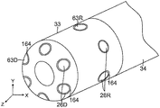
遠位先端部22の本体部25内には、図7Aに図示されているように、軸方向通路60及び、径方向通路62も形成されており、芯を抜かれた形状の近位領域29と、微小電極26が配置される、本体部25の外面33に形成された窪み64との間の連通を提供している。配線210と軸方向通路60とのそれぞれのペアが、先端部22内において互いに軸方向に整列しているが、配線210のコア218の内腔224を通っている追加的リードワイヤ40は、軸方向通路60及び径方向通路62を通って延び、遠位先端部22内のそれぞれの微小電極及び/又は温度検知器に接続されている。径方向微小電極26Rは、本体部25の径方向外面上に配置される。遠位側微小電極26Dは、本体部25の遠位側外面上に配置される。図示されている複数のワイヤ40は代表的なものにすぎず、それら複数のワイヤの数は、遠位先端部22上に保持される複数の微小電極の数と同数又はそれより多いということが理解される。1つの所定の配線210’のコア218の内腔224を、遠位側EM位置センサ42D用のケーブル36Dもまた通っている。配線210’の壁の一部分は、地点Xにおいて除去されて、EM位置センサ42Dから延びるケーブル36Dを収容する。
As shown in FIG. 7A, an
本発明の1つの特徴によると、窪み64は、その形状とサイズとが、微小電極26の形状とサイズとに対応するようになっている。微小電極26は、図7A及び7Cに図示するように、微小電極26の外面又は外向面63のみが露出し、遠位先端部22の本体部25の外面33と、概ね平行で、同じ高さになるように、それぞれ対応する窪み64内に完全に受容される本体部を有する。窪み64は、微小電極26が本体部25内部に埋め込まれて、滑らかで非侵襲的な輪郭を提供することを可能にするが、そのような輪郭により、微小電極が、遠位先端部22に接触している組織に引っかかったり、引っかいたり、又はその他の方法で損傷を与えるリスクを最小化できる。それぞれの窪みは、微小電極の外面63によるものを除いて、微小電極と組織との間の接触を、防ぐことはできないまでも、最小化する。窪みは、微小電極を、その外面以外囲むことにより、微小電極の側面又は内面のいずれによる組織との接触も制限する。
According to one feature of the present invention, the shape and size of the
また、微小電極26の外面63は、それを取り囲む基体本体部25の外面33の輪郭線と同じ輪郭線を有する。例えば、遠位側微小電極26Dは、基体本体部25の遠位端部における三次元曲面的な外面33に沿うような三次元曲面的な外面63Dを有し、径方向微小電極26Rは、基体本体部25の二次元曲線的外面33に沿うような二次元曲線的な外面63Rを有する。概ね滑らかな輪郭を有する先端部22は、その遠位端部の周りに、円周方向の動作で枢動することができ、その長手方向の軸線は円錐Cの軌跡をとり、特に、心房のような洞領域における組織への損傷のリスクを最小化しつつ、電極の接触を改善する。
Further, the outer surface 63 of the microelectrode 26 has the same contour line as the contour line of the
それぞれの微小電極26は、約0.05mm2〜0.5mm2の範囲の、好ましくは0.15mm2の表面積を有する。このように、遠位先端部22は、複数の、互いに近くに離間した微小な電極を備え、その電極は、例えば、パラジウム、白金、金、ステンレス鋼等、及びそれらを組み合わせたもののような、医療品質金属を含む、任意の好適な材料から形成されてよい。多くの微小電極26を有する先端部22は、微小電極の相対位置が先端部の本体部25に対して固定されていることを通じて正確に知られている微小電極の位置により、限局的診断能力を有利に提供する。その一方で、多くの環状電極240がスパイン27上に設けられているバスケットアセンブリ18は、心臓のような洞領域の内部の幾何学的形状の広いエリアを、医師がより迅速にカバーすることを可能にする。
Each micro electrode 26, in the range of about 0.05 mm 2 to 0.5 mm 2, preferably has a surface area of 0.15 mm 2. Thus, the
スパイン27上のそれぞれの環状電極240と、それぞれの微小電極26とは、リードワイヤ212及び40をそれぞれ介して、更に制御ハンドル16の近位端部に存在する、マルチピンコネクタ(不図示)を介して、カテーテルから遠く離れた適切なマッピングシステム及び/又はアブレーションのためのエネルギー源に電気的に接続されている。電極リードワイヤ212が壁内に埋め込まれ、追加的リードワイヤ40とEMセンサケーブル36が内腔224内に存在する配線210は、制御ハンドル16から、カテーテル本体12の中央内腔15と撓みセクション14の内腔32とを通り、更に、リードワイヤ212が環状電極に接続され、リードワイヤ40が遠位先端部22上の微小電極26に接続され、ケーブル36が遠位先端部22内のEMセンサに接続されるスパインと同様に、バスケットアセンブリ18を通って延びる。バスケットアセンブリ18を、微小電極を有する遠位先端部22と組み合わせることにより、カテーテルは、広いエリアのマッピングと、鋭敏な限局的マッピングとの両方に適応する。
Each
拡張器17は、カテーテルの全長にわたって延びる、好適な長さを有する。拡張器は、制御ハンドル16の近位側で露出している近位端部17P(図1)を含み、また、制御ハンドル16と、カテーテル本体12の中央内腔15と、撓みセクション14の内腔32とを通って延びる主要部分を含み、かつ、バスケットアセンブリ18を通り、遠位先端部22内へと延びる露出した遠位部位を含む。ガイド管23は、制御ハンドル16と、カテーテル本体の中央内腔15と、撓みセクション14の内腔32とを通って延びている。またガイド管23は、バスケットアセンブリ18の近位側接合部18Pの外管34の遠位端部の遠位側に短い距離だけ延びている遠位端部を有する。ユーザーは、拡張器17を制御ハンドル16及びカテーテルに対して長手方向に前進又は後退させて、近位端部17Pを操作するが、それにより、スパイン27の遠位端部が、カテーテルに対して近位方向又は遠位方向に動き、それぞれアセンブリ18を径方向に拡張させ又は収縮させる。
The
図3A及び3Bに示すように、撓みセクション14を一方向に屈曲させるための引張りワイヤ48が、制御ハンドル16から、カテーテル本体12の中央内腔15と、撓みセクション14の内腔31とを通って延びるが、制御ハンドル16内には、引張りワイヤ48の近位端部が固定され、制御ハンドル16上の屈曲用ノブ13に応答するようになっている。図6Aに示されるように、引張りワイヤ48の遠位端部は、撓みセクション14の遠位端部付近に、当該技術分野で既知のようにT−バー55によって固定される。図3Aに示すように、カテーテル本体12の内腔15の全長にわたり、引張りワイヤは圧縮コイル57によって取り囲まれている。圧縮コイルは、制御ハンドル16とカテーテル本体12との間の接合部に又はその付近に存在する近位端部と、カテーテル本体12の遠位端部に又はその付近に存在する遠位端部とを有する。したがって、引張りワイヤ48が、制御ハンドル16上の屈曲用ノブ13(図1)を操作することにより近位方向に引っ張られた場合には、圧縮コイル57はその長さ方向の圧縮を止めて、引張りワイヤ48が、カテーテル本体12の遠位側で、撓みセクション14を屈曲させる。カテーテルは、当該技術分野で既知のように、両方向の屈曲をさせるための、第2の引張りワイヤを含んでいてもよい。
As shown in FIGS. 3A and 3B, a pulling
遠位側電磁式位置センサ42Dが、センサケーブル36Dに接続されているが、同ケーブル36Dは、カテーテル本体12から延びる選択された配線210’(図3B)の内腔224と、制御ハンドル16とを通って延び、制御ハンドル16(図1)の近位端部から導管コード(不図示)内に出て、回路基板(不図示)を収容するセンサ制御モジュール(不図示)へと延びる。あるいは、例えば米国特許第6,024,739号に記載されているように、回路基板を制御ハンドル16内に収容することもできる。なお上記特許は、その開示内容が、参照により本明細書に組み込まれる。センサケーブル36Dは、プラスチック被覆シース内に入れられた複数のワイヤを含む。センサ制御モジュールにおいて、センサケーブルのワイヤは回路基板に接続されている。回路基板は、センサ制御モジュールの近位端部にあるセンサコネクタを用いて、対応する位置センサから受信された信号を増幅し、コンピュータに理解可能な形式でその信号をコンピュータに伝送する。また、カテーテルは単回使用専用で設計されるので、回路基板は、カテーテルが使用されてから約24時間後に回路基板を遮断するEPROMチップを含んでもよい。これにより、カテーテルが、あるいは少なくとも位置センサが、2回使用されることが防止される。
The distal
1つの実施形態においては、位置センサ42Dは、米国特許第5,391,199号に記載されているもののような磁場応答性コイル、又は、国際特許出願公開第96/05758号に記載のもののような、複数の上記コイルを備えている。複数のコイルにより、六次元的位置及び向き座標の決定が可能になる。あるいは、例えば、電気センサ、磁気センサ、又は音響センサのような、当該技術分野で既知の、任意の好適な位置センサを用いてもよい。本発明による使用に好適な位置センサは、例えば、米国特許第5,558,091号、同第5,443,489号、同第5,480,422号、同第5,546,951号、及び同第5,568,809号、並びに国際特許出願公開第95/02995号,同第97/24983号、及び同第98/29033号にも記述され、それらの開示内容は、参照により本明細書に組み込まれる。1つの実施形態においては、電磁式マッピングセンサは、約3mm〜約7mm、好ましくは約4mmの長さを有する。
In one embodiment, the
図6Aに破線で示されているように、近位側EM位置センサ42Pが、バスケットアセンブリ18の近位端部に設けられてもよい。センサ42Pは、外管34に収容され、近位側位置センサ42P用のケーブル36P(図6A中に、これも破線で示されている)が、カテーテル本体12の中央内腔15と、撓みセクション14の内腔32とを通して延びていてもよい。別の位置センサにより、近位側センサ42Pの座標に対する、遠位側センサ42Dの相対座標が決定され、バスケット形状のマッピングアセンブリ18のスパイン27の曲率に関する他の既知の情報と一緒に集められる。この情報は、スパイン26上に装着した環状電極240の位置を求めるために用いられる。
As shown by the dashed line in FIG. 6A, the proximal
当業者には認識されるように、近位側接合部及び遠位側接合部を構成するため、及び位置センサを装着するための他の配置も、本発明により用いられ得る。 Other arrangements for constructing the proximal and distal joints and for mounting the position sensor, as will be appreciated by those skilled in the art, may also be used by the present invention.
遠位先端部22は、任意の数の微小電極26を保持していてよい。例えば、遠位先端部22は、図8に示すように、16個の微小電極26(8個の遠位側微小電極及び8個の径方向微小電極)を保持していてよい。又は、図9に示すように、6個の微小電極26(3個の遠位側微小電極及び3個の径方向微小電極)を保持していてよい。図9及び図10を参照すると、フォーカルカテーテル100の遠位側部位が、撓みセクション114から延びる遠位先端部122とともに図示されている。更に図10A及び10Bを参照すると、遠位先端部122が、遠位先端部22に対して上で説明したのと同様の方法で構成されている。遠位先端部122は、非金属製の、電気的絶縁性の基体本体部125と、表面に埋め込まれた複数の、径方向微小電極26Rと遠位側微小電極26Dとを含み、径方向微小電極26Rの外面63Rと、遠位側微小電極26Dの外面63Dとはそれぞれ、基体本体部125の外面133と、概ね同じ高さになっており、概ね滑らかで、非侵襲的な遠位先端部の輪郭をもたらしている。基体本体部125は、リードワイヤ用に同様の軸方向通路160及び径方向通路162と、埋め込み式微小電極用に窪み164を有する。遠位側位置センサ142Dは、基体本体部125の近位端部に形成された止まり穴51内に配置される。しかしながら、本実施形態においては、フォーカルカテーテル100は、カテーテル内を、制御ハンドル16から遠位先端部122へと長手方向に延びるガイドワイヤ通路130を有して構成される。通路130は、制御ハンドルと、カテーテル本体の中央内腔と、撓みセクション114内の専用オン軸内腔141とを通って延びる管128、及び撓みセクション114と遠位先端部122とを接続しているコネクタ管134の内腔により定められる。管128の遠位端部は、基体本体部125内に形成された、長手方向のオン軸通路170内に受容されて、ガイドワイヤ通路130を、基体本体部の遠位面に延ばす。
The
フォーカルカテーテル100は、撓みセクション114の管内に形成された、直径方向で互いに反対の位置にある、オフ軸内腔31A及び31Bを通って延びる第1の引張りワイヤ48A及び第2の引張りワイヤ48Bを介して両方向に屈曲させられてもよい。
The
本発明のカテーテル100を使用するために、電気生理学医は、当該分野において一般に知られているように、拡張器とガイド用シースを患者に導入する。本発明のカテーテルと関連させて用いるために好適なガイド用シースは、PREFACE(商標)編組みガイド用シース(カリフォルニア州ダイアモンドバーのBiosense Webster社より市販されている)である。カテーテルが、バスケットアセンブリがガイド用シース内にフィード可能なように、その拡張器を延ばし、バスケットアセンブリを収縮させた状態で、ガイド用シースを通して導入される。ガイド用シースは、収縮位置にあるバスケットアセンブリのスパインを覆っており、カテーテル全体が、患者の脈管系を通って、所望の位置に達することができるようになっている。カテーテルのバスケットアセンブリが、所望の位置、例えば左心房に到着すると、ガイド用シースを後退させて、バスケットアセンブリを露出させる。スパインが外側に曲がるように、拡張器が近位方向に引っ張られるか、又は他の操作がなされる。バスケットアセンブリが径方向に拡張した状態で、環状電極が心房の組織と接触する。スパイン上の環状電極を、位置センサと組み合わせて用いて、患者に診断を下し治療を提供する際に、電気生理学医は、局所的作動時間をマッピングし、かつ/又はアブレーション及び灌水を必要に応じて実行する。バスケットアセンブリ上の多数の電極を有して、本カテーテルは、従来のカテーテルよりも多くの点を計測することにより、電気生理学医が、心房を含む心臓の洞領域の、真の解剖学的構造を得ることを可能にし、同領域をより迅速にマッピングすることを可能にする。また、限局的に組織と接触するためには、電気生理学医は、心臓組織のよりかすかな電気的活性を検知する際に、高密度微小電極を有する遠位先端部を向けることができ、より良い位置精度及びより高感度を実現することができる。
To use the
上記の説明文は、本発明の、現在開示された実施形態を参照して提示したものである。本発明が関係する分野及び技術の当業者であれば、本発明の原理、趣旨、及び範囲を大きく逸脱することなく、説明された構造の改変及び変更が実施されてもよいことを理解するであろう。当業者には理解されるように、図面は必ずしも実寸ではなく、また、その望むところ又は必要に応じて、1つの実施形態のいかなる特徴も、他の任意の実施形態に取り込むことが可能であり、又は、別の実施形態の任意の他の特徴と組み合わせることが可能である。したがって、上記の説明は、添付図面で説明及び図示した厳密な構造のみに関するものとして読まれるべきではなく、むしろ、以下の特許請求の範囲と一致し、かつそれを支持するものとして読まれるべきであり、この特許請求の範囲が完全かつ公正な範囲を有することになる。 The above description is presented with reference to the currently disclosed embodiments of the present invention. Those skilled in the art of the arts and arts to which the invention relates will appreciate that the structural modifications and alterations described may be made without significant deviations from the principles, gist and scope of the invention. There will be. As will be appreciated by those skilled in the art, the drawings are not necessarily full size and any features of one embodiment can be incorporated into any other embodiment wherever desired or as desired. , Or can be combined with any other feature of another embodiment. Therefore, the above description should not be read solely as relating to the exact structure described and illustrated in the accompanying drawings, but rather as consistent with and in support of the following claims. Yes, the scope of this claim has a complete and fair scope.
〔実施の態様〕
(1) 近位端部及び遠位端部、並びに中を通る少なくとも1つの内腔を有する細長いカテーテル本体と、
前記カテーテル本体の前記遠位端部に存在するバスケット電極アセンブリと、を備えるカテーテルであって、前記バスケット電極アセンブリが近位端部と遠位端部とを有し、かつ複数のスパインを備え、前記スパインが複数の電極を備え、前記遠位端部が基体本体部及び複数の埋め込み式微小電極を備え、前記基体本体部が外面を有し、かつ前記埋め込み式微小電極の外面が前記基体本体部の前記外面と同じ高さになっている、カテーテル。
(2) 前記基体本体部が径方向外面を有し、かつ少なくとも1つの径方向微小電極が、前記径方向外面と同じ高さになっている外面を有する、実施態様1に記載のカテーテル。
(3) 前記基体本体部の前記径方向外面と、前記少なくとも1つの径方向微小電極の前記外面とが、少なくとも1つの方向において共通の曲率を有している、実施態様2に記載のカテーテル。
(4) 前記基体本体部が遠位端部外面を有し、かつ少なくとも1つの遠位側微小電極が、前記遠位端部外面と同じ高さになっている外面を有する、実施態様1に記載のカテーテル。
(5) 前記基体本体部の前記遠位端部外面と、前記少なくとも1つの遠位側微小電極の前記外面とが、少なくとも1つの方向において共通の曲率を有している、実施態様4に記載のカテーテル。
[Implementation]
(1) An elongated catheter body having at least one lumen passing through the proximal and distal ends, and
A catheter comprising a basket electrode assembly present at the distal end of the catheter body, wherein the basket electrode assembly has a proximal end and a distal end and comprises a plurality of spines. The spine comprises a plurality of electrodes, the distal end portion comprises a substrate body and a plurality of implantable microelectrodes, the substrate body has an outer surface, and the outer surface of the implantable microelectrodes is the substrate body. A catheter that is flush with the outer surface of the portion.
(2) The catheter according to the first embodiment, wherein the base body portion has a radial outer surface, and at least one radial microelectrode has an outer surface having the same height as the radial outer surface.
(3) The catheter according to the second embodiment, wherein the radial outer surface of the substrate main body and the outer surface of the at least one radial microelectrode have a common curvature in at least one direction.
(4) In the first embodiment, the substrate main body has an outer surface at the distal end, and at least one distal microelectrode has an outer surface at the same height as the outer surface at the distal end. The catheter described.
(5) The fourth embodiment, wherein the outer surface of the distal end portion of the main body of the substrate and the outer surface of the at least one distal microelectrode have a common curvature in at least one direction. Catheter.
(6) 近位端部と遠位端部とを有し、かつ前記アセンブリの長手方向軸線を形成する拡張器を更に備え、前記スパインが、それらの近位端部と遠位端部とにおいて、前記拡張器に取り付けられている、実施態様1に記載のカテーテル。
(7) 前記カテーテル本体と前記バスケット電極アセンブリとの間にある、中間撓みセクションを更に備える、実施態様1に記載のカテーテル。
(8) 前記カテーテル本体と前記中間撓みセクションとを通って延びる、少なくとも1本の引張りワイヤを更に備え、該引張りワイヤが、前記中間撓みセクションの前記近位端部に、又はその付近に固定されている遠位端部を有する、実施態様7に記載のカテーテル。
(9) 前記カテーテル本体の近位側にある制御ハンドルを更に備え、該制御ハンドルが、前記少なくとも1本の引張りワイヤを動かすように適合されているアクチュエータを有する、実施態様8に記載のカテーテル。
(10) 前記基体本体部の前記外面が、前記微小電極を受容する1つ又はそれより多くの窪みを有する、実施態様1に記載のカテーテル。
(6) and a proximal end and a distal end, and further comprising a dilator to form a longitudinal axis of the assembly, the spine, in a their proximal end of the distal end , The catheter according to
(7) The catheter according to
(8) Further comprising at least one tension wire extending through the catheter body and the intermediate flexion section, the tension wire being fixed to or near the proximal end of the intermediate flexure section. The catheter according to embodiment 7, which has a distal end.
(9) The catheter according to
(10) The catheter according to the first embodiment, wherein the outer surface of the base body has one or more recesses that receive the microelectrodes.
(11) 前記窪みが、前記微小電極の外向きの面以外の、前記微小電極のすべての面を概ね覆うようなサイズ及び形状になっている、実施態様10に記載のカテーテル。
(12) 近位端部及び遠位端部、並びに中を通る少なくとも1つの内腔を有する細長いカテーテル本体と、
外面と通路とを有する基体本体部、及び複数の埋め込み式微小電極を備える、遠位先端部と、を備えるカテーテルであって、
前記埋め込み式微小電極の外面が、前記基体本体部の前記外面と同じ高さになっており、かつ
前記微小電極用のリードワイヤが、前記通路を通っている、カテーテル。
(13) それぞれの微小電極が、それを取り囲む、前記基体本体部の外面を有し、それぞれの微小電極の前記外面と、それを取り囲む、前記基体本体部の外面とが、共通の曲率を有する、実施態様12に記載のカテーテル。
(14) 前記微小電極が、少なくとも1つの径方向微小電極と、少なくとも1つの遠位側微小電極とを含み、前記基体本体部が、径方向外面と遠位側外面とを有し、前記少なくとも1つの径方向微小電極の外面と、前記基体本体部の前記径方向外面とが、第1の共通の曲率を有し、かつ前記少なくとも1つの遠位側微小電極の外面と、前記基体本体部の前記遠位側外面とが、第2の共通の曲率を有する、実施態様12に記載のカテーテル。
(15) 前記基体本体部が、非金属製の、電気的絶縁性材料を含む、実施態様12に記載のカテーテル。
(11) The catheter according to the tenth embodiment, wherein the recess is sized and shaped so as to substantially cover all surfaces of the microelectrode except for the outward surface of the microelectrode.
(12) An elongated catheter body having a proximal end and a distal end, and at least one lumen passing through.
A catheter comprising a substrate body having an outer surface and a passageway, and a distal tip having a plurality of implantable microelectrodes.
A catheter in which the outer surface of the implantable microelectrode is flush with the outer surface of the substrate body, and the lead wire for the microelectrode passes through the passage.
(13) Each microelectrode has an outer surface of the base body that surrounds it, and the outer surface of each microelectrode and the outer surface of the base body that surrounds it have a common curvature. , The catheter according to
(14) The microelectrode includes at least one radial microelectrode and at least one distal microelectrode, and the substrate body has a radial outer surface and a distal outer surface, at least. The outer surface of one radial microelectrode and the radial outer surface of the substrate body have a first common curvature, and the outer surface of at least one distal microelectrode and the
(15) The catheter according to
(16) 少なくとも前記カテーテル本体を通って延びる、ガイドワイヤ通路を更に備える、実施態様12に記載のカテーテル。
(17) 前記ガイドワイヤ通路が、前記遠位先端部を通って延びる、実施態様16に記載のカテーテル。
(18) 少なくとも16個の微小電極を備える、実施態様12に記載のカテーテル。
(19) 前記微小電極は、少なくとも8個の径方向微小電極と、少なくとも8個の遠位側微小電極とを含む、実施態様18に記載のカテーテル。
(20) 少なくとも6個の微小電極を備える、実施態様12に記載のカテーテル。
(16) The catheter according to
(17) The catheter according to
(18) The catheter according to
(19) The catheter according to
(20) The catheter according to
Claims (18)
近位端部及び遠位端部、並びに中を通る少なくとも1つの内腔を有する細長いカテーテル本体と、
前記カテーテル本体の前記遠位端部に存在するバスケット電極アセンブリと、を備え、
前記バスケット電極アセンブリが近位端部と遠位端部とを有し、かつ複数のスパインを備え、前記複数のスパインのそれぞれが複数の電極を備え、前記バスケット電極アセンブリの前記遠位端部が基体本体部及び複数の埋め込み式微小電極を備え、前記複数の埋め込み式微小電極用のリードワイヤのそれぞれが前記複数のスパインのそれぞれの中を通っており、前記基体本体部が外面を有し、前記埋め込み式微小電極の外面が前記基体本体部の前記外面と同じ高さになっている、カテーテル。 It ’s a catheter,
An elongated catheter body with proximal and distal ends, and at least one lumen passing through,
With a basket electrode assembly located at the distal end of the catheter body,
The basket electrode assembly has a proximal end and a distal end and comprises a plurality of spines , each of the plurality of spines having a plurality of electrodes, and the distal end of the basket electrode assembly. A base body portion and a plurality of implantable microelectrodes are provided, each of the lead wires for the plurality of implantable microelectrodes passes through each of the plurality of spines , and the substrate body portion has an outer surface. A catheter in which the outer surface of the implantable microelectrode is flush with the outer surface of the substrate body.
近位端部及び遠位端部、並びに中を通る少なくとも1つの内腔を有する細長いカテーテル本体と、
前記カテーテル本体の前記遠位端部に存在するバスケット電極アセンブリであって、近位端部及び遠位端部を有し、複数のスパインを備え、前記複数のスパインのそれぞれが複数の電極を備える、バスケット電極アセンブリと、
前記バスケット電極アセンブリの前記遠位端部に存在する遠位先端部であって、外面と通路とを有する基体本体部、及び複数の埋め込み式微小電極を備える、遠位先端部と、を備え、
前記複数の埋め込み式微小電極の外面が、前記基体本体部の前記外面と同じ高さになっており、
前記複数の埋め込み式微小電極用のリードワイヤのそれぞれが、前記通路の中と前記複数のスパインのそれぞれの中とを通っている、カテーテル。 It ’s a catheter,
An elongated catheter body with proximal and distal ends, and at least one lumen passing through,
A basket electrode assembly present at the distal end of the catheter body, having a proximal end and a distal end, comprising a plurality of spines , each of the plurality of spines comprising a plurality of electrodes. , Basket electrode assembly, and
A distal tip present at the distal end of the basket electrode assembly, comprising a substrate body having an outer surface and a passage, and a distal tip comprising a plurality of implantable microelectrodes.
The outer surface of the plurality of implantable microelectrodes has the same height as the outer surface of the base body.
Wherein each of the plurality of implantable lead wires for the microelectrodes have through each and in the spine and the front Symbol plurality within the passageway, the catheter.
Applications Claiming Priority (2)
| Application Number | Priority Date | Filing Date | Title |
|---|---|---|---|
| US14/526,394 US9314208B1 (en) | 2014-10-28 | 2014-10-28 | Basket catheter with microelectrode array distal tip |
| US14/526,394 | 2014-10-28 |
Related Child Applications (1)
| Application Number | Title | Priority Date | Filing Date |
|---|---|---|---|
| JP2020164935A Division JP7032501B2 (en) | 2014-10-28 | 2020-09-30 | Basket catheter with distal tip of microelectrode array |
Publications (3)
| Publication Number | Publication Date |
|---|---|
| JP2016083372A JP2016083372A (en) | 2016-05-19 |
| JP2016083372A5 JP2016083372A5 (en) | 2020-01-09 |
| JP6771878B2 true JP6771878B2 (en) | 2020-10-21 |
Family
ID=54360284
Family Applications (2)
| Application Number | Title | Priority Date | Filing Date |
|---|---|---|---|
| JP2015210478A Active JP6771878B2 (en) | 2014-10-28 | 2015-10-27 | Basket catheter with distal tip of microelectrode array |
| JP2020164935A Active JP7032501B2 (en) | 2014-10-28 | 2020-09-30 | Basket catheter with distal tip of microelectrode array |
Family Applications After (1)
| Application Number | Title | Priority Date | Filing Date |
|---|---|---|---|
| JP2020164935A Active JP7032501B2 (en) | 2014-10-28 | 2020-09-30 | Basket catheter with distal tip of microelectrode array |
Country Status (7)
| Country | Link |
|---|---|
| US (5) | US9314208B1 (en) |
| EP (2) | EP3015064B1 (en) |
| JP (2) | JP6771878B2 (en) |
| CN (1) | CN105534518B (en) |
| CA (1) | CA2910626A1 (en) |
| IL (1) | IL241381B (en) |
| RU (1) | RU2015145807A (en) |
Families Citing this family (52)
| Publication number | Priority date | Publication date | Assignee | Title |
|---|---|---|---|---|
| US8945117B2 (en) | 2009-02-11 | 2015-02-03 | Boston Scientific Scimed, Inc. | Insulated ablation catheter devices and methods of use |
| EP2788078B1 (en) | 2011-12-09 | 2020-09-02 | Metavention, Inc. | Therapeutic neuromodulation of the hepatic system |
| EP3206612B1 (en) | 2014-10-13 | 2022-06-29 | Boston Scientific Scimed Inc. | Tissue diagnosis and treatment using mini-electrodes |
| US9314208B1 (en) * | 2014-10-28 | 2016-04-19 | Biosense Webster (Israel) Ltd. | Basket catheter with microelectrode array distal tip |
| WO2016117238A1 (en) * | 2015-01-23 | 2016-07-28 | テルモ株式会社 | Guide wire |
| US11020017B2 (en) * | 2015-02-16 | 2021-06-01 | Biosense Webster (Israel) Ltd. | Angioplasty guidewire |
| US10602983B2 (en) | 2015-05-08 | 2020-03-31 | St. Jude Medical International Holding S.À R.L. | Integrated sensors for medical devices and method of making integrated sensors for medical devices |
| US10799287B2 (en) * | 2015-07-07 | 2020-10-13 | Boston Scientific Scimed, Inc. | Medical device having extenable members |
| US10376170B2 (en) | 2015-08-10 | 2019-08-13 | Boston Scientific Scimed, Inc. | Catheter with annular lumen to provide distal flushing |
| CN108289709B (en) | 2015-10-21 | 2022-03-04 | 圣犹达医疗用品心脏病学部门有限公司 | High-density electrode mapping catheter |
| US10639022B2 (en) * | 2015-11-03 | 2020-05-05 | W. L. Gore & Associates, Inc. | Endoscopic organ manipulation devices and methods |
| US10595782B2 (en) | 2015-12-20 | 2020-03-24 | Boston Scientific Scimed Inc | Micro induction position sensor |
| US10128594B2 (en) * | 2015-12-22 | 2018-11-13 | Biosense Webster (Israel) Ltd. | Connectors having three-dimensional surfaces |
| US10595745B2 (en) | 2016-01-29 | 2020-03-24 | Boston Scientific Scimed Inc. | Force sensing catheter with impedance-guided orientation |
| JP5976973B1 (en) * | 2016-03-28 | 2016-08-24 | インター・ノバ株式会社 | Peripheral blood vessel guide catheter with multipolar electrodes |
| US10362991B2 (en) * | 2016-04-04 | 2019-07-30 | Biosense Webster (Israel) Ltd. | Convertible basket catheter |
| WO2017192712A1 (en) * | 2016-05-03 | 2017-11-09 | St. Jude Medical, Cardiology Division, Inc. | Irrigated high density electrode catheter |
| US10537260B2 (en) * | 2016-05-06 | 2020-01-21 | Biosense Webster (Israel) Ltd. | Varying diameter catheter distal end design for decreased distal hub size |
| CN107440788A (en) * | 2016-06-01 | 2017-12-08 | 四川锦江电子科技有限公司 | A kind of ablation catheter and ablating device with interpolar discharge function |
| US10524859B2 (en) | 2016-06-07 | 2020-01-07 | Metavention, Inc. | Therapeutic tissue modulation devices and methods |
| US11369431B2 (en) | 2016-06-11 | 2022-06-28 | Boston Scientific Scimed Inc. | Inductive double flat coil displacement sensor |
| CN106237513B (en) * | 2016-08-28 | 2019-01-22 | 杭州瑞彼加医疗科技有限公司 | Non-intruding infiltration type radio frequency diagnostic equipment |
| US10485609B2 (en) * | 2016-10-18 | 2019-11-26 | Acclarent, Inc. | Dilation balloon with RF energy delivery feature |
| US11786705B2 (en) | 2016-10-24 | 2023-10-17 | St. Jude Medical, Cardiology Division, Inc. | Catheter insertion devices |
| EP3554406A1 (en) * | 2016-12-19 | 2019-10-23 | Boston Scientific Scimed Inc. | Distally-facing electrode array with longitudinally mounted splines |
| US10014607B1 (en) * | 2017-03-13 | 2018-07-03 | Bionsense Webster (Israel) Ltd. | PCB sub-connectors |
| US11647935B2 (en) | 2017-07-24 | 2023-05-16 | St. Jude Medical, Cardiology Division, Inc. | Masked ring electrodes |
| CN107468331A (en) * | 2017-08-21 | 2017-12-15 | 常州朗合医疗器械有限公司 | Radio frequency ablation catheter and system |
| US10359464B2 (en) | 2017-09-18 | 2019-07-23 | Biosense Webster (Israel) Ltd. | Cable and associated continuity monitoring system and method |
| EP3473200B1 (en) | 2017-10-23 | 2020-10-07 | VascoMed GmbH | Ablation catheter with microelectrode and method for producing an ablation catheter |
| US11484359B2 (en) | 2017-10-31 | 2022-11-01 | Biosense Webster (Israel) Ltd. | Method and system for gap detection in ablation lines |
| EP3681427B1 (en) | 2017-11-28 | 2023-10-18 | St. Jude Medical, Cardiology Division, Inc. | Controllable expandable catheter |
| JP2021510326A (en) * | 2018-01-10 | 2021-04-22 | アトリキュア, インコーポレイテッド | Equipment and accessories for perforated endoscope access and ablation systems |
| US20210052854A1 (en) * | 2018-04-09 | 2021-02-25 | Magellan Biomedical Inc. | System and method for device steering,tracking, and navigation of devices for interventional procedures |
| US11642063B2 (en) | 2018-08-23 | 2023-05-09 | St. Jude Medical, Cardiology Division, Inc. | Curved high density electrode mapping catheter |
| US11918762B2 (en) | 2018-10-03 | 2024-03-05 | St. Jude Medical, Cardiology Division, Inc. | Reduced actuation force electrophysiology catheter handle |
| US11357451B2 (en) * | 2018-12-10 | 2022-06-14 | Oscor Inc. | Intravascular mapping catheter with irrigated basket assembly |
| US11045628B2 (en) | 2018-12-11 | 2021-06-29 | Biosense Webster (Israel) Ltd. | Balloon catheter with high articulation |
| US20220167899A1 (en) * | 2019-04-04 | 2022-06-02 | St. Jude Medical Cardiology Division, Inc. | System and method for cardiac mapping |
| US11850051B2 (en) | 2019-04-30 | 2023-12-26 | Biosense Webster (Israel) Ltd. | Mapping grid with high density electrode array |
| US20210085386A1 (en) * | 2019-09-20 | 2021-03-25 | Biosense Webster (Israel) Ltd. | Catheter instrument with three pull wires |
| US11950930B2 (en) | 2019-12-12 | 2024-04-09 | Biosense Webster (Israel) Ltd. | Multi-dimensional acquisition of bipolar signals from a catheter |
| US11517218B2 (en) | 2019-12-20 | 2022-12-06 | Biosense Webster (Israel) Ltd. | Selective graphical presentation of electrophysiological parameters |
| US11950841B2 (en) | 2020-09-22 | 2024-04-09 | Biosense Webster (Israel) Ltd. | Basket catheter having insulated ablation electrodes and diagnostic electrodes |
| US11950840B2 (en) | 2020-09-22 | 2024-04-09 | Biosense Webster (Israel) Ltd. | Basket catheter having insulated ablation electrodes |
| US11918383B2 (en) | 2020-12-21 | 2024-03-05 | Biosense Webster (Israel) Ltd. | Visualizing performance of catheter electrodes |
| CN114404034A (en) * | 2021-02-09 | 2022-04-29 | 杭州德诺电生理医疗科技有限公司 | Ablation device |
| US20230053064A1 (en) * | 2021-08-16 | 2023-02-16 | Biosense Webster (Israel) Ltd. | Catheter having electrodes with adjustable size |
| US20230075838A1 (en) | 2021-09-09 | 2023-03-09 | Biosense Webster (Israel) Ltd. | Basket Catheter with Mushroom Shape Distal Tip |
| US20230210580A1 (en) | 2021-12-30 | 2023-07-06 | Biosense Webster (Isreal) Ltd. | Coated Microelectrodes |
| WO2023148597A1 (en) | 2022-02-02 | 2023-08-10 | Biosense Webster (Israel) Ltd. | Medical device with adjustment knob and feedback mechanism |
| WO2024072900A1 (en) * | 2022-09-28 | 2024-04-04 | St. Jude Medical, Cardiology Division, Inc. | High density paddle catheter with distal coupler and distal electrode |
Family Cites Families (34)
| Publication number | Priority date | Publication date | Assignee | Title |
|---|---|---|---|---|
| US5345936A (en) * | 1991-02-15 | 1994-09-13 | Cardiac Pathways Corporation | Apparatus with basket assembly for endocardial mapping |
| US5772590A (en) | 1992-06-30 | 1998-06-30 | Cordis Webster, Inc. | Cardiovascular catheter with laterally stable basket-shaped electrode array with puller wire |
| US5391199A (en) | 1993-07-20 | 1995-02-21 | Biosense, Inc. | Apparatus and method for treating cardiac arrhythmias |
| IL116699A (en) | 1996-01-08 | 2001-09-13 | Biosense Ltd | Method of constructing cardiac map |
| US5558091A (en) | 1993-10-06 | 1996-09-24 | Biosense, Inc. | Magnetic determination of position and orientation |
| EP1364677A3 (en) * | 1993-11-10 | 2006-12-27 | Medtronic, Inc. | Electrode array catheter |
| EP0776176B1 (en) | 1994-08-19 | 1999-12-29 | Biosense, Inc. | Medical diagnosis, treatment and imaging systems |
| US5595264A (en) | 1994-08-23 | 1997-01-21 | Trotta, Jr.; Frank P. | System and method for automated shopping |
| US5836875A (en) * | 1995-10-06 | 1998-11-17 | Cordis Webster, Inc. | Split tip electrode catheter |
| PT893967E (en) | 1997-01-03 | 2004-07-30 | Biosense Inc | CATHETER CONFORMAVEL |
| US7218958B2 (en) * | 2004-02-23 | 2007-05-15 | St. Jude Medical, Atrial Fibrillation Division, Inc. | Electrophysiology/ablation catheter having second passage |
| US6024739A (en) | 1997-09-05 | 2000-02-15 | Cordis Webster, Inc. | Method for detecting and revascularizing ischemic myocardial tissue |
| US6064905A (en) | 1998-06-18 | 2000-05-16 | Cordis Webster, Inc. | Multi-element tip electrode mapping catheter |
| US20040092806A1 (en) | 2001-12-11 | 2004-05-13 | Sagon Stephen W | Microelectrode catheter for mapping and ablation |
| US6748255B2 (en) | 2001-12-14 | 2004-06-08 | Biosense Webster, Inc. | Basket catheter with multiple location sensors |
| US6741878B2 (en) | 2001-12-14 | 2004-05-25 | Biosense Webster, Inc. | Basket catheter with improved expansion mechanism |
| US6980858B2 (en) * | 2001-12-31 | 2005-12-27 | Biosense Webster, Inc. | Method and system for atrial defibrillation |
| US7163537B2 (en) | 2003-06-02 | 2007-01-16 | Biosense Webster, Inc. | Enhanced ablation and mapping catheter and method for treating atrial fibrillation |
| US7818048B2 (en) * | 2003-06-02 | 2010-10-19 | Biosense Webster, Inc. | Catheter and method for mapping a pulmonary vein |
| JP5336465B2 (en) * | 2007-03-26 | 2013-11-06 | ボストン サイエンティフィック リミテッド | High resolution electrophysiology catheter |
| US8224416B2 (en) | 2007-05-09 | 2012-07-17 | St. Jude Medical, Atrial Fibrillation Division, Inc. | Basket catheter having multiple electrodes |
| US8588885B2 (en) * | 2007-05-09 | 2013-11-19 | St. Jude Medical, Atrial Fibrillation Division, Inc. | Bendable catheter arms having varied flexibility |
| US8103327B2 (en) * | 2007-12-28 | 2012-01-24 | Rhythmia Medical, Inc. | Cardiac mapping catheter |
| US8712550B2 (en) * | 2008-12-30 | 2014-04-29 | Biosense Webster, Inc. | Catheter with multiple electrode assemblies for use at or near tubular regions of the heart |
| US20100168557A1 (en) | 2008-12-30 | 2010-07-01 | Deno D Curtis | Multi-electrode ablation sensing catheter and system |
| US8414579B2 (en) | 2009-06-30 | 2013-04-09 | Boston Scientific Scimed, Inc. | Map and ablate open irrigated hybrid catheter |
| US20120203316A1 (en) | 2011-02-08 | 2012-08-09 | Boston Scientific Neuromodulation Corporation | Leads with segmented electrodes for electrical stimulation of planar regions and methods of making and using |
| US8900228B2 (en) * | 2011-09-01 | 2014-12-02 | Biosense Webster (Israel) Ltd. | Catheter adapted for direct tissue contact and pressure sensing |
| US9050010B2 (en) * | 2012-12-31 | 2015-06-09 | Biosense Webster (Israel) Ltd. | Double loop lasso with single puller wire for bi-directional actuation |
| US9474486B2 (en) * | 2013-03-08 | 2016-10-25 | St. Jude Medical, Atrial Fibrillation Division, Inc. | Basket for a multi-electrode array catheter |
| US10602947B2 (en) | 2013-04-11 | 2020-03-31 | Biosense Webster (Israel), Ltd. | High density electrode structure |
| US9204929B2 (en) | 2013-09-16 | 2015-12-08 | Biosense Webster (Israel) Ltd. | Basket catheter with deflectable spine |
| US20150082693A1 (en) | 2013-09-24 | 2015-03-26 | John Patrick Griffin | Multipurpose, Adjustable, Collapsible and Portable Stand |
| US9314208B1 (en) * | 2014-10-28 | 2016-04-19 | Biosense Webster (Israel) Ltd. | Basket catheter with microelectrode array distal tip |
-
2014
- 2014-10-28 US US14/526,394 patent/US9314208B1/en active Active
-
2015
- 2015-09-09 IL IL241381A patent/IL241381B/en active IP Right Grant
- 2015-10-23 RU RU2015145807A patent/RU2015145807A/en not_active Application Discontinuation
- 2015-10-26 CA CA2910626A patent/CA2910626A1/en not_active Abandoned
- 2015-10-27 JP JP2015210478A patent/JP6771878B2/en active Active
- 2015-10-27 EP EP15191615.2A patent/EP3015064B1/en active Active
- 2015-10-27 EP EP16171704.6A patent/EP3075311A1/en not_active Withdrawn
- 2015-10-28 CN CN201510711419.2A patent/CN105534518B/en active Active
-
2016
- 2016-04-18 US US15/132,198 patent/US9693733B2/en active Active
-
2017
- 2017-07-03 US US15/641,182 patent/US10039494B2/en active Active
-
2018
- 2018-08-03 US US16/054,715 patent/US10470714B2/en active Active
-
2019
- 2019-11-11 US US16/680,269 patent/US10939871B2/en active Active
-
2020
- 2020-09-30 JP JP2020164935A patent/JP7032501B2/en active Active
Also Published As
| Publication number | Publication date |
|---|---|
| RU2015145807A3 (en) | 2019-04-24 |
| JP2016083372A (en) | 2016-05-19 |
| US10039494B2 (en) | 2018-08-07 |
| IL241381B (en) | 2019-02-28 |
| US20160228062A1 (en) | 2016-08-11 |
| CN105534518B (en) | 2021-12-07 |
| EP3015064A3 (en) | 2016-11-02 |
| JP7032501B2 (en) | 2022-03-08 |
| EP3015064B1 (en) | 2023-06-07 |
| US9314208B1 (en) | 2016-04-19 |
| US20180338722A1 (en) | 2018-11-29 |
| US20170296125A1 (en) | 2017-10-19 |
| US9693733B2 (en) | 2017-07-04 |
| US10939871B2 (en) | 2021-03-09 |
| JP2021007767A (en) | 2021-01-28 |
| CA2910626A1 (en) | 2016-04-28 |
| CN105534518A (en) | 2016-05-04 |
| IL241381A0 (en) | 2015-11-30 |
| RU2015145807A (en) | 2017-04-27 |
| EP3015064A2 (en) | 2016-05-04 |
| US10470714B2 (en) | 2019-11-12 |
| EP3075311A1 (en) | 2016-10-05 |
| US20160113582A1 (en) | 2016-04-28 |
| US20200077959A1 (en) | 2020-03-12 |
Similar Documents
| Publication | Publication Date | Title |
|---|---|---|
| JP7032501B2 (en) | Basket catheter with distal tip of microelectrode array | |
| JP6736290B2 (en) | Basket catheter with improved spine flexibility | |
| JP7242816B2 (en) | A catheter having a closed loop array with in-plane linear electrode segments | |
| EP2653098B1 (en) | Mapping catheter with spiral electrode assembly | |
| JP2016083372A5 (en) | ||
| JP7077020B2 (en) | Catheter with support structure with variable dimensions | |
| JP7102149B2 (en) | Multi-electrode assembly with controlled folding mechanism | |
| JP2017170142A (en) | Dispersed irrigation configuration for catheter tip design | |
| JP6869665B2 (en) | High electrode density basket catheter | |
| JP2017200584A (en) | Varying diameter catheter distal end design for decreased distal hub size |
Legal Events
| Date | Code | Title | Description |
|---|---|---|---|
| A621 | Written request for application examination |
Free format text: JAPANESE INTERMEDIATE CODE: A621 Effective date: 20181026 |
|
| A131 | Notification of reasons for refusal |
Free format text: JAPANESE INTERMEDIATE CODE: A131 Effective date: 20190827 |
|
| A977 | Report on retrieval |
Free format text: JAPANESE INTERMEDIATE CODE: A971007 Effective date: 20190823 |
|
| A524 | Written submission of copy of amendment under article 19 pct |
Free format text: JAPANESE INTERMEDIATE CODE: A524 Effective date: 20191120 |
|
| A521 | Request for written amendment filed |
Free format text: JAPANESE INTERMEDIATE CODE: A523 Effective date: 20191122 |
|
| A131 | Notification of reasons for refusal |
Free format text: JAPANESE INTERMEDIATE CODE: A131 Effective date: 20200428 |
|
| A521 | Request for written amendment filed |
Free format text: JAPANESE INTERMEDIATE CODE: A523 Effective date: 20200722 |
|
| TRDD | Decision of grant or rejection written | ||
| A01 | Written decision to grant a patent or to grant a registration (utility model) |
Free format text: JAPANESE INTERMEDIATE CODE: A01 Effective date: 20200804 |
|
| A601 | Written request for extension of time |
Free format text: JAPANESE INTERMEDIATE CODE: A601 Effective date: 20200903 |
|
| A61 | First payment of annual fees (during grant procedure) |
Free format text: JAPANESE INTERMEDIATE CODE: A61 Effective date: 20200930 |
|
| R150 | Certificate of patent or registration of utility model |
Ref document number: 6771878 Country of ref document: JP Free format text: JAPANESE INTERMEDIATE CODE: R150 |
|
| R250 | Receipt of annual fees |
Free format text: JAPANESE INTERMEDIATE CODE: R250 |