JP6770540B2 - Electronics and methods - Google Patents
Electronics and methods Download PDFInfo
- Publication number
- JP6770540B2 JP6770540B2 JP2018022252A JP2018022252A JP6770540B2 JP 6770540 B2 JP6770540 B2 JP 6770540B2 JP 2018022252 A JP2018022252 A JP 2018022252A JP 2018022252 A JP2018022252 A JP 2018022252A JP 6770540 B2 JP6770540 B2 JP 6770540B2
- Authority
- JP
- Japan
- Prior art keywords
- power supply
- supply request
- power
- transmission
- signal
- Prior art date
- Legal status (The legal status is an assumption and is not a legal conclusion. Google has not performed a legal analysis and makes no representation as to the accuracy of the status listed.)
- Active
Links
- 238000000034 method Methods 0.000 title claims description 48
- 230000005540 biological transmission Effects 0.000 claims description 181
- 230000004044 response Effects 0.000 claims description 44
- 230000008054 signal transmission Effects 0.000 claims description 6
- 239000003990 capacitor Substances 0.000 claims description 3
- 238000004891 communication Methods 0.000 description 271
- 238000012545 processing Methods 0.000 description 77
- 238000007726 management method Methods 0.000 description 19
- 230000006870 function Effects 0.000 description 18
- 238000012790 confirmation Methods 0.000 description 12
- 238000005259 measurement Methods 0.000 description 10
- 238000012546 transfer Methods 0.000 description 10
- 238000010586 diagram Methods 0.000 description 8
- 230000008569 process Effects 0.000 description 8
- 101100172132 Mus musculus Eif3a gene Proteins 0.000 description 5
- 239000013078 crystal Substances 0.000 description 5
- 230000008859 change Effects 0.000 description 4
- 230000006835 compression Effects 0.000 description 3
- 238000007906 compression Methods 0.000 description 3
- 230000006837 decompression Effects 0.000 description 3
- 239000000284 extract Substances 0.000 description 3
- 238000012986 modification Methods 0.000 description 3
- 230000004048 modification Effects 0.000 description 3
- 238000012806 monitoring device Methods 0.000 description 3
- 230000010355 oscillation Effects 0.000 description 3
- 238000006243 chemical reaction Methods 0.000 description 2
- 238000012937 correction Methods 0.000 description 2
- 238000010295 mobile communication Methods 0.000 description 2
- 238000012544 monitoring process Methods 0.000 description 2
- 238000004260 weight control Methods 0.000 description 2
- HBBGRARXTFLTSG-UHFFFAOYSA-N Lithium ion Chemical compound [Li+] HBBGRARXTFLTSG-UHFFFAOYSA-N 0.000 description 1
- 230000005856 abnormality Effects 0.000 description 1
- 238000004458 analytical method Methods 0.000 description 1
- 238000003491 array Methods 0.000 description 1
- 239000000969 carrier Substances 0.000 description 1
- 239000004020 conductor Substances 0.000 description 1
- 238000010276 construction Methods 0.000 description 1
- 238000013500 data storage Methods 0.000 description 1
- 230000003111 delayed effect Effects 0.000 description 1
- 229920005994 diacetyl cellulose Polymers 0.000 description 1
- 230000005674 electromagnetic induction Effects 0.000 description 1
- 238000005516 engineering process Methods 0.000 description 1
- 238000010191 image analysis Methods 0.000 description 1
- 238000009434 installation Methods 0.000 description 1
- 229910001416 lithium ion Inorganic materials 0.000 description 1
- 230000007774 longterm Effects 0.000 description 1
- 230000003287 optical effect Effects 0.000 description 1
- 238000004549 pulsed laser deposition Methods 0.000 description 1
- 230000009467 reduction Effects 0.000 description 1
- 230000000717 retained effect Effects 0.000 description 1
- 238000004904 shortening Methods 0.000 description 1
- 229910000679 solder Inorganic materials 0.000 description 1
- 239000000758 substrate Substances 0.000 description 1
- 230000001360 synchronised effect Effects 0.000 description 1
- 230000002194 synthesizing effect Effects 0.000 description 1
- 238000009827 uniform distribution Methods 0.000 description 1
Images


Classifications
-
- H—ELECTRICITY
- H02—GENERATION; CONVERSION OR DISTRIBUTION OF ELECTRIC POWER
- H02J—CIRCUIT ARRANGEMENTS OR SYSTEMS FOR SUPPLYING OR DISTRIBUTING ELECTRIC POWER; SYSTEMS FOR STORING ELECTRIC ENERGY
- H02J50/00—Circuit arrangements or systems for wireless supply or distribution of electric power
- H02J50/20—Circuit arrangements or systems for wireless supply or distribution of electric power using microwaves or radio frequency waves
-
- H04B5/79—
-
- H—ELECTRICITY
- H02—GENERATION; CONVERSION OR DISTRIBUTION OF ELECTRIC POWER
- H02J—CIRCUIT ARRANGEMENTS OR SYSTEMS FOR SUPPLYING OR DISTRIBUTING ELECTRIC POWER; SYSTEMS FOR STORING ELECTRIC ENERGY
- H02J50/00—Circuit arrangements or systems for wireless supply or distribution of electric power
- H02J50/40—Circuit arrangements or systems for wireless supply or distribution of electric power using two or more transmitting or receiving devices
-
- H—ELECTRICITY
- H02—GENERATION; CONVERSION OR DISTRIBUTION OF ELECTRIC POWER
- H02J—CIRCUIT ARRANGEMENTS OR SYSTEMS FOR SUPPLYING OR DISTRIBUTING ELECTRIC POWER; SYSTEMS FOR STORING ELECTRIC ENERGY
- H02J50/00—Circuit arrangements or systems for wireless supply or distribution of electric power
- H02J50/80—Circuit arrangements or systems for wireless supply or distribution of electric power involving the exchange of data, concerning supply or distribution of electric power, between transmitting devices and receiving devices
-
- H—ELECTRICITY
- H02—GENERATION; CONVERSION OR DISTRIBUTION OF ELECTRIC POWER
- H02J—CIRCUIT ARRANGEMENTS OR SYSTEMS FOR SUPPLYING OR DISTRIBUTING ELECTRIC POWER; SYSTEMS FOR STORING ELECTRIC ENERGY
- H02J7/00—Circuit arrangements for charging or depolarising batteries or for supplying loads from batteries
- H02J7/00032—Circuit arrangements for charging or depolarising batteries or for supplying loads from batteries characterised by data exchange
- H02J7/00034—Charger exchanging data with an electronic device, i.e. telephone, whose internal battery is under charge
Description
本発明の実施形態は、電子装置および無線通信方法に関する。 Embodiments of the present invention relate to electronic devices and wireless communication methods.
ワイヤレス給電は、電磁誘導、磁界共振、電波などにより、ケーブルなしに電力の伝送を実現する技術である。ワイヤレス給電では、装置どうしを物理的に接続する必要がないため、利便性が高い。また、漏電や感電のリスクが軽減されるため、安全性を確保することができる。これらの利点があるため、特にモバイルや車載の分野においてワイヤレス給電が普及しつつある。 Wireless power supply is a technology that realizes power transmission without cables by electromagnetic induction, magnetic field resonance, radio waves, and the like. Wireless power supply is very convenient because it is not necessary to physically connect the devices. In addition, since the risk of electric leakage and electric shock is reduced, safety can be ensured. Because of these advantages, wireless power supply is becoming widespread, especially in the mobile and in-vehicle fields.
ワイヤレス給電では、様々な方式の開発が進められているが、充電時間の短縮、伝送可能な電力の増大など、効率的な給電方式を実現することが課題となっている。特に無線方式による給電は、1台の送信装置から、複数台の無線端末に給電できるため、一層の普及が期待されている。 Various methods of wireless power supply are being developed, but the challenge is to realize an efficient power supply method such as shortening the charging time and increasing the power that can be transmitted. In particular, the wireless power supply can supply power to a plurality of wireless terminals from one transmitter, and is expected to become more widespread.
本発明の実施形態は、給電装置から効率的に給電を受ける無線通信装置および無線通信方法を提供する。 An embodiment of the present invention provides a wireless communication device and a wireless communication method that efficiently receive power from a power supply device.
本発明の一実施形態としての電子装置は、第1給電要求を送信する送信部と、前記第1給電要求に応じた第1無線信号を受信し、前記第1無線信号に基づく電力を蓄電装置に充電する受電部と、前記受電部における前記第1無線信号の前記受信履歴に基づき、第2給電要求の送信タイミングを決定する制御部と、を備える。 An electronic device according to an embodiment of the present invention receives a transmission unit that transmits a first power supply request and a first radio signal corresponding to the first power supply request, and stores power based on the first radio signal. It is provided with a power receiving unit for charging the power receiving unit and a control unit for determining the transmission timing of the second power supply request based on the reception history of the first radio signal in the power receiving unit.
以下、図面を参照しながら、本発明の実施形態について説明する。 Hereinafter, embodiments of the present invention will be described with reference to the drawings.
(第1の実施形態)
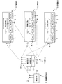
図1は、本実施形態に係る全体のシステム構成例を示す図である。図1を用いて、本実施形態の概要を説明する。図1のシステムは、基地局(給電装置)1と、無線通信端末2と、複数の受電端末3とを備える。図では無線通信端末2の台数は3台であるが、1台以上であればよい。
(First Embodiment)
FIG. 1 is a diagram showing an example of an overall system configuration according to the present embodiment. The outline of this embodiment will be described with reference to FIG. The system of FIG. 1 includes a base station (power supply device) 1, a wireless communication terminal 2, and a plurality of power receiving terminals 3. In the figure, the number of wireless communication terminals 2 is three, but it may be one or more.
基地局1は、例えばIEEE802.11シリーズまたはその後継規格の無線LAN(Local Area Network)規格に準拠した無線通信装置(電子装置)である。基地局1は、アクセスポイント(AP)と呼ばれることもある。ここで、無線LANは例示であり、基地局1の用いる無線通信方式は、IEEE802.16シリーズ又はその後継規格の移動体通信方式、またはその他の通信方式であってもよい。 The base station 1 is, for example, a wireless communication device (electronic device) compliant with the IEEE802.11 series or its successor standard wireless LAN (Local Area Network) standard. Base station 1 is sometimes called an access point (AP). Here, the wireless LAN is an example, and the wireless communication system used by the base station 1 may be an IEEE 802.16 series or a mobile communication system of a successor standard, or another communication system.
基地局1は更にBLE(Bluetooth(登録商標) Low Energy)による通信も可能である。BLE以外の通信、例えば、ZigBee(登録商標)、Z−Wave(登録商標)、Wireless USB、無線LAN通信などを行ってもよい。NFC(Near field radio communication)なども排除されない。 Base station 1 can also communicate by BLE (Bluetooth (registered trademark) Low Energy). Communication other than BLE, for example, ZigBee (registered trademark), Z-Wave (registered trademark), Wireless USB, wireless LAN communication, etc. may be performed. NFC (Near field radio communication) and the like are not excluded.
基地局1は、無線LAN等の無線通信が可能な通信回路11と、BLEに対応したBLE回路12と、制御回路13とを備えている。制御回路13は、通信回路11およびBLE回路12の制御を行う。基地局1は、通信回路11が送受信に用いるアンテナ14と、BLE回路12が送受信に用いるアンテナ15とを備える。アンテナ14は1つでも複数であってもよく、アンテナの種類や形状は特に問わない。アンテナ15は1つでも複数であってもよく、アンテナの種類や形状は特に問わない。
The base station 1 includes a
無線通信端末2は、例えばIEEE802.11シリーズまたはその後継規格の無線LAN(Local Area Network)規格に準拠した無線通信装置である。無線通信端末2は、ステーション(STA)と呼ばれることもある。無線通信端末2の用いる通信方式も、IEEE802.16シリーズ又はその後継規格の移動体通信方式またはその他の通信方式であってもよい。ただし、無線通信端末2は、基地局1の用いる無線通信方式と同一または互換性のある無線通信規格に対応しているものとする。 The wireless communication terminal 2 is, for example, a wireless communication device compliant with the IEEE802.11 series or its successor standard, the wireless LAN (Local Area Network) standard. The wireless communication terminal 2 is sometimes called a station (STA). The communication method used by the wireless communication terminal 2 may also be an IEEE 802.16 series or a successor standard mobile communication method or another communication method. However, it is assumed that the wireless communication terminal 2 corresponds to a wireless communication standard that is the same as or compatible with the wireless communication method used by the base station 1.
無線通信端末2は、1つまたは複数のアンテナ21と、通信回路22とを備える。
The wireless communication terminal 2 includes one or
各受電端末3は、BLEによる通信が可能な無線通信装置である。各受電端末3は、アンテナ4と、整流回路5と、蓄電装置6と、BLE回路7と、BLE用のアンテナ8と、センサ9と、制御回路10を備えている。アンテナ4と整流回路5は合わせてレクテナ(rectifying antenna)として動作する。蓄電装置6は電力(電荷)の蓄積と、放出とが可能である。蓄電装置6は、リチウムイオン電池などの小型の2次電池(蓄電池)でもよいし、キャパシタでよい。本実施形態では蓄電池を想定し、以下では蓄電装置6を蓄電池6と記述する。BLE回路7は、主にBLEによる通信機能を提供する。
Each power receiving terminal 3 is a wireless communication device capable of communicating by BLE. Each power receiving terminal 3 includes an antenna 4, a
本実施形態においては、基地局1の通信回路11と、無線通信端末2の通信回路22とは無線LANによる通信を行うものとして説明をする。ただし、無線LANは例示であり、その他の無線通信方式を用いることを排除するものではない。
In the present embodiment, the
基地局1、無線通信端末2、各受電端末3は、自動車に搭載された機器であるとして説明をする。ただし、自動車は例示であり、鉄道車両、船舶、航空機、建設機械、ロボットなどその他の移動体上にあってもよいし、発電所、工場などの施設上にあってもよく、設置場所は特に問わない。 The base station 1, the wireless communication terminal 2, and each power receiving terminal 3 will be described as being mounted on an automobile. However, automobiles are examples, and may be on other moving objects such as railroad cars, ships, aircraft, construction machinery, robots, or on facilities such as power plants and factories, and the installation location is particularly high. It doesn't matter.
無線通信端末2は一例として車載カメラである。各受電端末3は一例として各種の監視センサである。監視センサの具体例としては、タイヤ空気圧センサ、エンジン温度センサ、室内の温度センサなどがあるが、これらに限定されない。 The wireless communication terminal 2 is, for example, an in-vehicle camera. Each power receiving terminal 3 is an example of various monitoring sensors. Specific examples of the monitoring sensor include, but are not limited to, a tire pressure sensor, an engine temperature sensor, and an indoor temperature sensor.
基地局1および無線通信端末2は、自動車に搭載されたバッテリーまたは自装置に搭載されたバッテリーにより動作する。バッテリーは一次電池でも、二次電池でもよい。 The base station 1 and the wireless communication terminal 2 are operated by a battery mounted on an automobile or a battery mounted on its own device. The battery may be a primary battery or a secondary battery.
受電端末3におけるBLE回路7は、蓄電池6に蓄積された電力により動作する。またセンサ9も、蓄電池6に蓄積された電力により動作する。受電端末3は、基地局1から無線LANで送信される無線信号(給電信号)をアンテナ4で受信する。受電端末3は、受信した無線信号を整流回路5で直流エネルギーに変換し、直流エネルギーを蓄電池6に蓄積する。
The
制御回路10は、BLE回路7を制御する。制御回路10は、基地局1に給電要求を送信するタイミング(送信タイミング)を決定し、決定した送信タイミングに応じて、BLE回路7を介して、基地局1に給電要求を送信する。
The
図1のシステムの動作の一例として、基地局1は、無線通信端末2から定期的または任意のタイミングで、映像データを受信する。基地局1は、受信した映像データを内部の記憶装置に格納し、図示しない表示装置(例えば経路誘導装置の画面)に表示したり、画像解析を実行したりする。 As an example of the operation of the system of FIG. 1, the base station 1 receives video data from the wireless communication terminal 2 at regular intervals or at arbitrary timings. The base station 1 stores the received video data in an internal storage device, displays it on a display device (for example, a screen of a route guidance device) (not shown), or executes image analysis.
基地局1は、受電端末3からの給電要求に応じて無線給電用の無線信号(給電信号)を受電端末3に送信することで、受電端末3に無線給電を行う。この際、基地局1は、複数のアンテナ14に設定したウエイトにより、受電端末3に指向性を有する電波であるビームを送信することで、ビームによる無線給電を行ってもよい。ビームは、複数のアンテナ14のウエイトで信号を重み付け合成することで生成される。なお、アンテナ自体が指向性可変である場合は、アンテナの設定を調整して、電波の指向性を制御してもよい。
The base station 1 wirelessly supplies power to the power receiving terminal 3 by transmitting a wireless power supply signal (power supply signal) to the power receiving terminal 3 in response to a power supply request from the power receiving terminal 3. At this time, the base station 1 may perform wireless power supply by the beam by transmitting a beam which is a radio wave having directivity to the power receiving terminal 3 by the weights set in the plurality of
また、基地局1は、BLE通信を行って、受電端末3から定期的にセンサデータを収集したり、受電端末3の受電量に関する情報(受電量情報)を収集したりする。基地局1は、受電量情報を利用して受電端末3への給電を制御してもよい。例えば、受電端末3へ送信するビームのためのアンテナのウエイト制御、変調方式の制御、使用する無線周波数チャネル(以下、チャネル)の制御、使用する帯域幅の制御等がある。また基地局1は、受電量情報を利用して、送電効率(受電効率)を計算してもよい。送電効率(受電効率)は一例として送電した電力量に対する受電した電力量の比により計算できる。電力量とは電気エネルギーまたは電荷量のことである。なお、基地局1が送信する無線信号(給電信号)は、連続波でもよいし(つまりBLEや無線LANなどの規格で定義される形式に従った信号でなくてよい)、無線LANなどの規格のフレームフォーマットに従った信号でもよい。 In addition, the base station 1 performs BLE communication to periodically collect sensor data from the power receiving terminal 3 and collect information (power receiving amount information) regarding the power received by the power receiving terminal 3. The base station 1 may control the power supply to the power receiving terminal 3 by using the power receiving amount information. For example, there are weight control of an antenna for a beam transmitted to a power receiving terminal 3, control of a modulation method, control of a radio frequency channel to be used (hereinafter, channel), control of a bandwidth to be used, and the like. Further, the base station 1 may calculate the power transmission efficiency (power reception efficiency) by using the power reception amount information. As an example, the transmission efficiency (power reception efficiency) can be calculated by the ratio of the received power amount to the transmitted power amount. The amount of electric power is the amount of electric energy or electric charge. The wireless signal (feeding signal) transmitted by the base station 1 may be a continuous wave (that is, it does not have to be a signal according to a format defined by a standard such as BLE or wireless LAN), or a standard such as wireless LAN. It may be a signal according to the frame format of.
以下の説明では、無線LANで使用する周波数帯域と、BLEで使用する周波数帯域は異なるものとする。例えば無線LANでは、5GHz帯域を利用し、Bluetoothの一種であるBLEでは2.4GHz帯域を利用しているとする。ただし、無線LANがBLEと同じ2.4GHz帯域を利用し、無線LANとBLEの周波数帯域が重なっていてもよい。 In the following description, it is assumed that the frequency band used in the wireless LAN and the frequency band used in the BLE are different. For example, it is assumed that a wireless LAN uses a 5 GHz band, and BLE, which is a type of Bluetooth, uses a 2.4 GHz band. However, the wireless LAN may use the same 2.4 GHz band as the BLE, and the frequency bands of the wireless LAN and the BLE may overlap.
本実施形態に係る受電端末3は基地局1に適切なタイミングで給電要求を送信することで、基地局1からの無線給電を効率的に行うことを特徴の1つとする。基地局1および無線通信端末2は、自動車のバッテリーからのエネルギーで動作するため、エンジンの始動とともにエネルギーが供給され、ただちに動作可能となる。これに対して、受電端末3は、基地局1から受信する無線信号に基づく電力を蓄電池6に充電して動作するため、適宜、充電を行う必要がある。この際、蓄電池6の最低電力量を維持する必要がある場合もある。
基地局1は、1つ以上の受電端末3に対して給電および通信を行い、1つ以上の無線通信端末2とも通信を行うため、受電端末3は、給電要求を送信後、いつ基地局1から自端末への無線信号が送信されるのかが事前に分かるとは限らない。また、無線信号の長さや送信回数も事前に分からない場合もある。このような状況の中で、受電端末3は適切なタイミングで給電要求を行うことで、蓄電池6の最低電力量を維持したり、所定の時刻までに給電が完了するようにしたりする。本実施形態では、給電要求送信後の基地局1からの無線信号の受信状況を予測し、それを考慮して給電要求の送信タイミングを決定する。
One of the features of the power receiving terminal 3 according to the present embodiment is that wireless power supply from the base station 1 is efficiently performed by transmitting a power supply request to the base station 1 at an appropriate timing. Since the base station 1 and the wireless communication terminal 2 are operated by the energy from the battery of the automobile, the energy is supplied at the start of the engine and the wireless communication terminal 2 can be operated immediately. On the other hand, since the power receiving terminal 3 operates by charging the
Since the base station 1 supplies power and communicates to one or more power receiving terminals 3 and also communicates with one or more wireless communication terminals 2, the power receiving terminal 3 sends a power supply request and then when the base station 1 1 is used. It is not always known in advance whether a wireless signal is transmitted from the terminal to the own terminal. In addition, the length of the radio signal and the number of transmissions may not be known in advance. In such a situation, the power receiving terminal 3 makes a power supply request at an appropriate timing to maintain the minimum electric energy of the
以下、図1の基地局1、無線通信端末2および受電端末3についてさらに詳細に説明する。 Hereinafter, the base station 1, the wireless communication terminal 2, and the power receiving terminal 3 of FIG. 1 will be described in more detail.
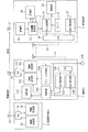
図2は、第1の実施形態に従った無線通信システムのブロック図である。なお、本実施形態において各図で共通する名称の要素には同一の符号を付して、重複する説明は適宜省略する。 FIG. 2 is a block diagram of a wireless communication system according to the first embodiment. In the present embodiment, the elements having the same name in each figure are designated by the same reference numerals, and duplicate description will be omitted as appropriate.
本実施形態に係る無線通信システムは、基地局1と、無線通信端末2と、受電端末3とを備える。図2では、受電端末3は1台であるが、実際には複数台存在してよい(図1参照)。 The wireless communication system according to the present embodiment includes a base station 1, a wireless communication terminal 2, and a power receiving terminal 3. Although the number of power receiving terminals 3 is one in FIG. 2, a plurality of power receiving terminals 3 may actually exist (see FIG. 1).
基地局1が搭載する無線通信装置(電子装置)は、無線通信用の1つまたは複数のアンテナ14と、BLE用の1つまたは複数のアンテナ15と、スイッチ101と、無線受信部102と、無線送信部103と、フレーム生成部104と、制御部105と、スイッチ106と、BLE受信部107と、BLE送信部108と、IF部109と、記憶部110とを備える。
The wireless communication device (electronic device) mounted on the base station 1 includes one or
スイッチ101は、アンテナ14を無線送信部103または無線受信部102へ切り換えるためのスイッチである。
The
フレーム生成部104は、無線通信端末2に送信するためのフレームを生成する。基地局1が無線LANによる通信をする場合、フレームはMACフレームである。無線LAN規格のフレームには、データフレーム、管理フレーム、制御フレームがあるが、これらのいずれであってもよい。
The
基地局1が定期的に自身の属性または同期情報を通知するために送信するビーコンフレームは、管理フレームである。また、制御フレームには、相手の端末に送信要求を行うためのRTS(Request to Send)フレーム、送信許可を与えるためのCTS(Clear to Send)フレーム、送達確認フレームであるACKフレームまたはBA(Block Ack)フレームなどがある。ここで列挙したフレームは一例であり、他にも様々なフレームが存在する。 The beacon frame transmitted by the base station 1 to periodically notify its own attribute or synchronization information is a management frame. Further, the control frame includes an RTS (Request to Send) frame for making a transmission request to the other terminal, a CTS (Clear to Send) frame for giving transmission permission, an ACK frame or a BA (Block) which is a delivery confirmation frame. Ac) There are frames and so on. The frames listed here are examples, and there are various other frames.
無線送信部103は、フレーム生成部104で生成されたフレームを、アンテナ14を介して送信する。フレームは、実際には、物理レイヤのヘッダが付加されてパケットとされ、パケットが送信される。無線送信部103は、フレーム(より詳細にはパケット)に対して、誤り訂正符号化と変調を行い、変調信号を生成する。変調信号は、アナログ信号に変換される。無線送信部103は、発振器とPLL(Phase Locked Loop)回路を用いて一定周波数の信号を生成しており、当該一定周波数の信号に基づいて、送信用ミキサで、アナログ信号を、無線周波数の信号にアップコンバートする。無線送信部103は、アップコンバートした信号を、RFアンプにより増幅し、増幅された信号を、アンテナから空間へ電波として送信する。これにより、無線周波数のフレーム(パケット)が送信される。
The
また、無線送信部103は、制御部105の制御のもと、無線給電用の無線信号(給電信号)を生成し、無線信号を、アンテナ14を介して送信する。より詳細には、無線送信部103は、制御部105により指定される給電パラメータに従って無線信号を生成する。無線信号は、フレームまたはパケットの送信時に用いる発振器の出力信号またはPLL回路の出力信号を利用して生成できる。一例として、給電パラメータに応じた給電用データを、送信用ミキサで当該出力信号にかけ合わせることで、無線信号を生成してもよい。無線信号用の信号源を用意し、当該信号源を利用して給電パラメータから無線信号を生成することも可能である。
Further, the
なお、受電端末3へ送信する無線信号として、フレーム生成部104で生成するフレームを用いることも可能である。例えばビーコンフレームを、無線信号として用いることも可能である。あるいは、無線給電用のフレームを定義して、当該フレームを無線信号として送信してもよい。
It is also possible to use a frame generated by the
制御部105は、フレーム生成部104を用いて、無線通信端末2との通信を制御する。
The
また、制御部105は、給電パラメータの設定を制御する。給電パラメータの設定項目の例として、複数のアンテナごとのウエイトがある。また、変調方式または変調符号化方式(MCS:Modulation and Coding Scheme)がある。または、使用するチャネルがある。例えば、無線LANの帯域に存在する複数のチャネルのうち使用するチャネルがある。
Further, the
ウエイトとは送信信号の振幅および位相の調整値を意味する。アンテナごとに、送信する信号の振幅および位相を調整することで、様々なビームを形成できる。受電端末3に適したビームを形成することで、伝送効率の高い無線信号の送信が可能となる。伝送効率とは、送信電力量に対する受電電力量の比である。 The weight means the adjusted value of the amplitude and the phase of the transmitted signal. Various beams can be formed by adjusting the amplitude and phase of the transmitted signal for each antenna. By forming a beam suitable for the power receiving terminal 3, it is possible to transmit a radio signal with high transmission efficiency. The transmission efficiency is the ratio of the received power amount to the transmitted power amount.
各アンテナにどのようなウエイトを設定すれば、受電端末3に好適なビーム(伝送効率の高いビーム)を形成できるかは事前に分からないことが多い。そこで、様々なウエイトで無線信号を送信し、受電量情報のフィードバックを受けることで、受電端末3に適したウエイトを決定することができる。 It is often unknown in advance what kind of weight should be set for each antenna to form a beam suitable for the power receiving terminal 3 (a beam having high transmission efficiency). Therefore, by transmitting wireless signals with various weights and receiving feedback of the received power amount information, it is possible to determine a weight suitable for the power receiving terminal 3.
上述した給電パラメータの設定項目は一例であり、他にも様々な項目を制御することが可能である。 The above-mentioned power supply parameter setting items are an example, and various other items can be controlled.
無線受信部102は、無線通信端末2から受信した信号を復調して、フレームを取得する。より詳細には、アンテナ14で受信された信号は、無線受信部102に入力される。無線受信部102は、受信された信号を、LNA(Low Noise Amplifier)アンプで増幅する。無線受信部102は、増幅された信号から受信用フィルタを用いて所望帯域の信号を抽出する。無線受信部102は、発振器とPLL回路で生成される一定周波数の信号に基づいて、抽出した信号をダウンコンバートする。無線受信部102は、復調および復号してフレームを得る。
The
無線受信部102は、取得したフレームがデータフレームであれば、データフレームに含まれるデータをIF部109から出力する。IF部109は、無線受信部102で受信したフレームを上位層または、上位層との間のバッファに出力するためのインターフェースである。また、無線受信部102は、受信したフレームの種類に応じた動作を行うため、フレームの解析結果をフレーム生成部104または制御部105に出力する。例えば送達確認応答を行う場合は、送達確認応答に必要な情報をフレーム生成部104または制御部105またはこれらの両方に出力し、受信完了から一定時間後に送達確認応答フレームを送信するようにする。
If the acquired frame is a data frame, the
スイッチ106は、アンテナ15をBLE受信部107またはBLE送信部108へ切り換えるためのスイッチである。
The
BLE受信部107は、BLEの信号を受信する。BLE受信部107は、BLE用のアンテナ15を介して、受電端末3からデータを受信する。受信するデータの例として、給電要求、センサデータ、および受電端末3が受電した受電量に関する情報(受電量情報)がある。
The
BLE受信部107は、制御部105に接続されており、受電端末3から受信した給電要求および受電量情報を制御部105に供給する。またBLE受信部107は、受電端末3から受信したセンサデータを車内の監視装置(図示せず)に送信する。監視装置は、センサデータに基づき、センシング箇所の異常の有無等を確認する。制御部105が監視装置の役割を兼ねてもよく、その場合、BLE受信部107は、センサデータを制御部105に供給する。
The
BLE送信部108は、制御部105に接続されており、アンテナ15を介して、データを受電端末3に送信する。BLE送信部108から受電端末3に送信されるデータの一例として、受電量の測定指示情報や、給電パラメータ(基地局1からの送信に使用する各アンテナのウエイト、送信電力など)などがある。
The
記憶部110は、制御部105に接続されており、制御データを保存する。記憶部110は、SRAM、DRAM等の揮発性メモリでも、NAND、MRAM、FRAM等の不揮発性メモリでもよい。またハードディスク、SSD等のストレージ装置でもよい。
The
基地局1における無線送信部103、無線受信部102およびフレーム生成部104は、一例として、図1に示した基地局1における通信回路11に対応する。基地局1における制御部105は、一例として、図1に示した基地局1における制御回路13に対応する。基地局1におけるBLE受信部107とBLE送信部108は、一例として、図1に示した基地局1におけるBLE回路12に対応する。
The
無線通信端末2が搭載する無線通信装置は、アンテナ23と、スイッチ24と、無線送信部25と、無線受信部26とを備える。スイッチ24は、アンテナ23を無線送信部25または無線受信部26へ切り換えるためのスイッチである。無線送信部25は、無線通信端末2で生成されたMACフレームを、アンテナ23を介して送信する。無線受信部26は、基地局1および他の無線通信端末からMACフレームを受信する。
The wireless communication device mounted on the wireless communication terminal 2 includes an
アンテナ23は、無線LANの信号を送受信可能なアンテナである。無線送信部25および無線受信部26は、基地局1の無線送信部103および無線受信部102と同様の機能を有する。無線送信部25および無線受信部26は、一例として、図1の無線通信端末2が備える通信回路22に対応する。
The
受電端末3が搭載する無線通信装置は、センサ9と、無線LAN用のアンテナ31と、受電部32と、受電量測定部33と、BLE送信部34と、BLE用のアンテナ35と、スイッチ36と、BLE受信部37と、記憶部38と、制御部39とを備える。
The wireless communication device mounted on the power receiving terminal 3 includes a
受電部32は、アンテナ31を介して、基地局1から送信される無線信号(給電信号)を受信し、受信した無線信号を直流に変換(整流)する。受電部32は、変換された直流電流を、蓄電池6に充電する。
The
受電量測定部33は、受信した無線信号の電力量(受電量)を測定する。受電量の測定方法は任意の方法でよい。例えば、測定前後の電圧の変化に応じて、受電量を求めてもよい。具体的には、測定前後の電圧の差分と、電池容量とから受電量を測定する。測定した受電量に関する情報は、記憶部38に保存される。
The power receiving
BLE送信部34は、BLEによる通信を行う。BLE送信部34は、測定された受電量に関する情報(受電量情報)を、BLE用のアンテナ35を介して、送信する。受電量情報は、一例として、測定された受電量を特定するための値を含む。受電量を特定するための値は、受電量の値でもよいし、測定前後の蓄電池6の電圧の変化値でもよい。蓄電池6の特性を基地局1側で把握できる場合には、電圧の変化値から、受電量を基地局1で計算することができる。受電量情報を基地局1にフィードバックすることで、基地局1は受電端末3に対して効率的なアンテナ14のウエイトを決定できる。なお、受電量情報を利用してアンテナ14のウエイトを変更することは動作の一例であり、基地局1はこのようなウエイト制御を行わなくてもよい。この場合、受電端末3における受電量測定を省略することも可能である。
The
スイッチ36は、アンテナ35をBLE送信部34またはBLE受信部37へ切り換えるためのスイッチである。
The
BLE受信部37は、BLEの信号を受信する。BLE受信部37は、BLE用のアンテナ35を介して、基地局1からデータを受信する。一例として、BLE受信部37は、基地局1から測定指示情報または給電パラメータを受信する。
The
記憶部38は、受電量測定部33で測定した受電量に関する情報(受電量情報)または任意のデータを保存する。記憶部38は、SRAM、DRAM等の揮発性メモリでも、NAND、MRAM、FRAM等の不揮発性メモリでも、ハードディスク、SSD等のストレージ装置でも、これらの組み合わせからなるものであってもよい。
The
制御部39は、受電量測定部33、BLE送信部34、BLE受信部37およびセンサ9を制御する。制御部39は、BLE送信部34を介して、基地局1に給電要求を送信する。給電要求は、一例として、基地局1から給電する送信電力量(給電量)、無線信号の送信回数、給電用に送信する無線信号の合計時間長、1回の送信あたりの無線信号の長さ、送信電力値等のうち少なくとも1つの設定値を含む。ただし、これらの設定値のうち事前にシステムまたは仕様で決まっているものがある場合は、その設定値については、給電要求に含めなくてもよい。制御部39は、上記給電要求の送信後の基地局1からの無線信号の受信履歴(例えば給電要求の送信後から無線信号が受信されるまでに経過した時間など)に基づき、次の給電要求の送信タイミングを決定する。送信タイミングは、一例として、蓄電池6の残存電力量が閾値以下になったタイミング、所定の時刻になったタイミングがある。ただし、送信タイミングはこれらに限定されない。例えば、基準となる時刻から所定時間が経過したタイミングでもよい。制御部39は、決定したタイミングで次の給電要求を、BLE送信部34を介して送信する。
The
受電端末3におけるアンテナ31および受電部32は、一例として、図1の受電端末3におけるアンテナ4、整流回路5および蓄電池6に対応する。受電端末3における受電量測定部33、BLE送信部34およびBLE受信部37は、一例として、図1の受電端末3におけるBLE回路7に対応する。制御部39は、一例として図1の受電端末3における制御回路10に対応する。
As an example, the
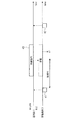
図3は、基地局1と受電端末3間の動作シーケンスの概要を示す。 FIG. 3 shows an outline of an operation sequence between the base station 1 and the power receiving terminal 3.
受電端末3は、予め定めた送信タイミングまたは任意のタイミングで、BLEで給電要求(第1給電要求)を基地局1に送信する(S11)。 The power receiving terminal 3 transmits a power supply request (first power supply request) to the base station 1 by BLE at a predetermined transmission timing or an arbitrary timing (S11).
基地局1は、受電端末3からBLEで第1給電要求を受信すると、第1給電要求に従って無線送信部103を用いて、受電端末3に対する給電処理を行う。例えば、給電量が指定されている場合、指定された給電量を供給可能な無線信号長を、事前に測定した送電効率に基づき算出し、算出した長さの無線信号を送信する。無線信号の最大長が定められている場合は、最大長を越えないように、必要に応じて複数回に分けて、無線信号を送信してもよい。無線信号の送信電力は予め定められていてもよいし、第1給電要求で指定してもよい。図の例では、無線信号が4回数送信する例が示されている(S12a、S12b、S12c、S12d)。ただし、無線信号の送信回数は、1回以上であれば、何回でもよい。
When the base station 1 receives the first power supply request from the power receiving terminal 3 via BLE, the base station 1 uses the
第1給電要求の送信後、基地局1から無線信号が送信されるまでの時間は、基地局1の動作状況および周囲の電波環境等に依存して変化する。また、基地局1からの無線信号の送信回数や、複数回数無線信号が送信される場合の各無線信号の間隔も同様である。例えば、基地局1は第1給電要求を受信後、無線通信端末2と通信を行ってから、第1給電要求を実行する場合もあれば、第1給電要求を受信後、即時に第1給電要求を実行する場合もある。また、ネットワークが混雑していなければ第1給電要求に応じた無線信号を即時に送信できるが、混雑していれば、無線媒体がアイドルになるまで、無線信号の送信を待機する必要がある。図の例では、ステップS12b、S12cにおける無線信号の送信間隔は、ステップS12a、S12bにおける無線信号の送信間隔、ステップS12c、S12dにおける無線信号の送信間隔より大きくなっている。 The time from the transmission of the first power supply request to the transmission of the radio signal from the base station 1 varies depending on the operating status of the base station 1 and the surrounding radio wave environment. Further, the number of times the radio signal is transmitted from the base station 1 and the interval between the radio signals when the radio signal is transmitted a plurality of times are also the same. For example, the base station 1 may execute the first power supply request after receiving the first power supply request and then communicating with the wireless communication terminal 2, or the first power supply immediately after receiving the first power supply request. It may also execute the request. Further, if the network is not congested, the radio signal corresponding to the first power supply request can be transmitted immediately, but if the network is congested, it is necessary to wait for the transmission of the radio signal until the wireless medium becomes idle. In the example of the figure, the radio signal transmission interval in steps S12b and S12c is larger than the radio signal transmission interval in steps S12a and S12b and the radio signal transmission interval in steps S12c and S12d.
受電端末3は、ステップS11での第1給電要求の送信後、基地局1から受信される無線信号の受信状況を測定することにより、無線信号の受信履歴(すなわち受電端末3における充電の実施状況)を取得する。受電端末3は、無線信号の受信履歴に基づき、次の給電要求(第2給電要求)の送信タイミングを決定する(S13)。受電端末3は、決定した送信タイミングで、第2給電要求をBLEで送信する(S14)。受電端末3は、第2給電要求に応じて基地局1から送信される無線信号を受信する(S15a)。 After transmitting the first power supply request in step S11, the power receiving terminal 3 measures the reception status of the wireless signal received from the base station 1 to obtain the reception history of the wireless signal (that is, the charging execution status at the power receiving terminal 3). ) To get. The power receiving terminal 3 determines the transmission timing of the next power supply request (second power supply request) based on the reception history of the radio signal (S13). The power receiving terminal 3 transmits the second power supply request by BLE at the determined transmission timing (S14). The power receiving terminal 3 receives the radio signal transmitted from the base station 1 in response to the second power supply request (S15a).
図4は、図3の動作シーケンスにおける受電端末3の動作のフローチャートである。受電端末3は、予め定めた送信タイミングまたは任意のタイミングで、BLEで給電要求(第1給電要求)を基地局1に送信する(S51)。受電端末3は、第1給電要求に応じて基地局1から送信される無線信号の受信する(S52)。受電端末3は、無線信号の受信状況を測定することにより、無線信号の受信履歴を取得する(S53)。受電端末3は、無線信号の受信履歴に基づき、次の給電要求(第2給電要求)の送信タイミングを決定する(S54)。受電端末3は、決定した送信タイミングで第2給電要求を送信する(S55)。 FIG. 4 is a flowchart of the operation of the power receiving terminal 3 in the operation sequence of FIG. The power receiving terminal 3 transmits a power supply request (first power supply request) to the base station 1 by BLE at a predetermined transmission timing or an arbitrary timing (S51). The power receiving terminal 3 receives the radio signal transmitted from the base station 1 in response to the first power supply request (S52). The power receiving terminal 3 acquires the reception history of the radio signal by measuring the reception status of the radio signal (S53). The power receiving terminal 3 determines the transmission timing of the next power supply request (second power supply request) based on the reception history of the radio signal (S54). The power receiving terminal 3 transmits the second power supply request at the determined transmission timing (S55).
以下、図5〜図12を用いて、図3で説明したシーケンスの動作について、第1の具体例〜第6の具体例を説明する。 Hereinafter, the first specific example to the sixth specific example will be described with respect to the operation of the sequence described in FIG. 3 with reference to FIGS. 5 to 12.
(第1の具体例)
図5は、本実施形態に係る無線通信システムにおける動作シーケンスの第1の具体例を示す。基地局1および受電端末3の動作が時間軸に沿って示されている。時間軸の上側が無線LANの動作、下側がBLEの動作を表す。本例では、受電端末3が給電要求を送信後、基地局1から無線信号を受信開始するまでの時間長を表す情報を取得し、取得した情報に基づき、次の給電要求の送信タイミングを決定する。
(First specific example)
FIG. 5 shows a first specific example of an operation sequence in the wireless communication system according to the present embodiment. The operations of the base station 1 and the power receiving terminal 3 are shown along the time axis. The upper side of the time axis shows the operation of the wireless LAN, and the lower side shows the operation of BLE. In this example, after the power receiving terminal 3 transmits the power supply request, information indicating the time length from the base station 1 to the start of receiving the wireless signal is acquired, and the transmission timing of the next power supply request is determined based on the acquired information. To do.
受電端末3は、予め定めたタイミングで、給電要求41を、BLEで送信する。予め定めたタイミングの例として、蓄電池6の残存電力量が閾値以下になった場合、予め定めた時刻になった場合(あるいは予め定めた期間に入った場合)がある。ここでは、蓄電池6の残存電力量が閾値以下になった場合を想定する。閾値は、一例として、蓄電池6に維持すべき最低電力量より大きい値である。また、タイミングのその他の例として、起動直後のタイミングなどがある。
The power receiving terminal 3 transmits the
基地局1は、給電要求41をBLEで受信し、給電要求41を解釈する。ここでは、給電要求41は、送信電力量(給電量)を指定しており、基地局1は、給電要求41で指定された量の電力を給電することを決定する。基地局1は、一例として予め測定した受電効率と、送電電力量とを乗じた値の電力量が受電端末3に供給されるように、送信する無線信号の長さを決定する。送信電力値は、事前に決まっているとするが、送信電力値が給電要求41で指定される場合は、指定された送信電力値を用いる。
The base station 1 receives the
基地局1は、CSMA/CA(Carrier Sense Multiple Access with Collision Avoidance)に従って、無線媒体へのアクセス権を獲得する。具体的に固定時間と、ランダムに決定したバックオフ時間との合計である待機時間の間、キャリアセンスを行い、無線媒体の状態がアイドルであると判定したら、アクセス権を獲得する。基地局1は、獲得したアクセス権に基づき、上記決定した長さの無線信号43を無線LANで送信する。基地局1は、複数のアンテナ14に設定したウエイトにより信号に重み付けし、受電端末3にビームによる無線給電を行ってもよい。
The base station 1 acquires the access right to the radio medium according to CSMA / CA (Carrier Sense Multiple Access with Collection Avision). Specifically, the carrier sense is performed during the standby time, which is the total of the fixed time and the backoff time determined at random, and when it is determined that the state of the wireless medium is idle, the access right is acquired. Based on the acquired access right, the base station 1 transmits the
受電端末3は、基地局1から送信される無線信号43を受信し、受信した無線信号43の電力を蓄電池6に充電する。
The power receiving terminal 3 receives the
また、受電端末3は、給電要求41の送信後、無線信号43が受信開始されるまでの時間T1を測定する。
Further, the power receiving terminal 3 measures the time T1 from the transmission of the
受電端末3は、時間T1に基づき、次の給電要求42の送信タイミングを決定する。時間T1は、給電要求を送信後、無線信号が受信開始されるまでの時間(給電応答時間)と見積もることができる。受電端末3は、受電端末3の動作消費電力(例えば平均消費電力)と、給電応答時間T1とに基づき、給電要求を送信するための上記閾値を変更する。具体的には、給電応答時間T1と同じ長さの時間で受電端末3が消費する消費電力量を計算し、蓄電池6の最低電力量に、計算した消費電力量を加算した値を、閾値に決定(すなわち閾値を更新)する。この際、マージンを考慮し、最低電力量に、計算した消費電力量と、マージン電力量αとを加算した値を閾値に決定してもよい。この場合、受電端末3は、蓄電池6の残存電力量が、変更後の閾値以下になったら、次の給電要求42をBLEで送信する。これにより、受電端末3は、蓄電池6の最低電力量を維持しつつ、蓄電池6を充電できることが期待できる。
The power receiving terminal 3 determines the transmission timing of the next
または、受電端末3は、最低電力量に給電応答時間T1と同じ長さの時間で消費する消費電力量を加算し、加算後の電力量に、蓄電池6の残算電力量がなる時刻(第1時刻)を、受電端末3の動作消費電力に基づき計算する。そして、第1時刻を、次の給電要求42の送信時刻としてもよい。この際、上記加算した電力量にマージン電力量αをさらに加算した電力量に残存電力量がなる時刻(第2時刻)を計算し、第2時刻を、次の給電要求42の送信時刻としてもよい。受電端末3は、第1時刻または第2時刻になったら、次の給電要求42を送信する。あるいは、受電端末3は、第2時刻から第1時刻までの期間を設定し、この期間を、次の給電要求42の送信期間として決定してもよい。この場合、受電端末3は、決定した送信期間内で、次の給電要求42を送信する。これにより、受電端末3は、蓄電池6の最低電力量を維持しつつ、蓄電池6を充電できることが期待できる。
Alternatively, the power receiving terminal 3 adds the power consumption amount consumed in the same length as the power supply response time T1 to the minimum power amount, and the time when the remaining power amount of the
ここで、図5のシーケンスにおいて、受電端末3が、給電要求41の送信後、無線信号43を受信開始する前に、他のシステムから送信される信号(雑音信号)や、基地局1が他の受電端末に送信する無線信号、あるいは他の受電端末3が送信する信号を受信する場合もある。
Here, in the sequence of FIG. 5, after the power receiving terminal 3 transmits the
一例として、図6に、基地局1が給電要求41を受信した後、無線信号43を送信する前に、無線通信端末2と通信を行う場合のシーケンスを示す。基地局1は、受電端末3から給電要求41を受信した後、データフレーム47を無線通信端末2に送信し、無線通信端末2は、データフレーム47の受信からSIFS後に、送達確認応答フレーム(ACKフレーム)48を応答として送信する。データフレーム47または送達確認応答フレーム48またはこれらの両方は、受電端末3でも受信あるいは検知される可能性がある。
As an example, FIG. 6 shows a sequence in which the base station 1 communicates with the wireless communication terminal 2 after receiving the
そこで、受電端末3は、受信した無線信号43が、給電要求41に係るものであるか否かを判断する手段を備えていてもよい。例えば所定値以上の電力値の受信信号が一定期間以上継続した場合は、当該受信した信号は給電要求41に係る無線信号であると判断してもよい。この際、当該受信した信号が、給電要求41の送信後一定期間以内のものであることを要件として追加してもよい。または、給電用の無線信号が無線LANのフォーマットのフレームを有する場合は、受信した無線信号のフレームの受信先アドレスが自端末のMACアドレスかを判断し、自端末のMACアドレスの場合は、受信した無線信号が、給電要求41に係るものであると判断してもよい。ここで述べた以外の方法で判断してもよい。
Therefore, the power receiving terminal 3 may be provided with a means for determining whether or not the received
なお、基地局1が受電端末3から受信した給電要求を実行するタイミングは特定のタイミングに限られない。例えば、基地局1が、図5または図6に示した受電端末3以外に、他の1つ又は複数の受電端末3から給電要求を受信する場合がある。この場合、基地局1は、一例として、早く受信した順に、給電要求を実行してもよい。あるいは、別の基準で実行する順番を制御してもよい。 The timing at which the base station 1 executes the power supply request received from the power receiving terminal 3 is not limited to a specific timing. For example, the base station 1 may receive a power supply request from one or more other power receiving terminals 3 in addition to the power receiving terminal 3 shown in FIG. 5 or FIG. In this case, as an example, the base station 1 may execute power supply requests in the order of earliest reception. Alternatively, the order of execution may be controlled based on another criterion.
また、基地局1は、受電端末3以外に、無線通信端末2とも通信している場合がある。その場合、無線通信端末2との通信と、給電要求の実行とのスケジューリングを任意の方法で行えばよい。例えば通信の要求および給電要求の発生(または受信)した順序で、当該要求および給電要求および実行してもよい。あるいは、無線通信端末2との一定数(例えば1つ)のフレームの送信または受信を1回分のタスクとし、給電要求に係る無線信号の1回の送信を1回分のタスクとする(給電要求が複数の無線信号の送信が行われる場合は、複数のタスクである)。そして、受電端末3の給電要求、他の受電端末3の給電要求、無線通信端末2との通信がそれぞれ1回分のタスクずつ順番に実行されるようにタスクの実行をスケジュールしてもよい。 Further, the base station 1 may communicate with the wireless communication terminal 2 in addition to the power receiving terminal 3. In that case, the communication with the wireless communication terminal 2 and the execution of the power supply request may be scheduled by any method. For example, the request and the power supply request and the power supply request may be executed in the order in which the communication request and the power supply request are generated (or received). Alternatively, the transmission or reception of a certain number (for example, one) of frames with the wireless communication terminal 2 is set as one task, and one transmission of the wireless signal related to the power supply request is set as one task (the power supply request is). Multiple tasks if multiple radio signals are transmitted). Then, the execution of the task may be scheduled so that the power supply request of the power receiving terminal 3, the power supply request of the other power receiving terminal 3, and the communication with the wireless communication terminal 2 are executed one by one in order.
(第2の具体例)
図7は、本実施形態に係る無線通信システムにおける動作シーケンスの第2の具体例を示す。基地局1および受電端末3の動作が時間軸に沿って示されている。時間軸の上側が無線LANの動作、下側がBLEの動作を表す。本例では、受電端末3が給電要求を送信後、給電要求に係る無線信号の受信が完了するまでの時間(充電完了時間)を取得し、取得した情報に基づき、次の給電要求の送信タイミングを決定する。図5のシーケンスと同じ動作の説明については適宜省略する。
(Second specific example)
FIG. 7 shows a second specific example of the operation sequence in the wireless communication system according to the present embodiment. The operations of the base station 1 and the power receiving terminal 3 are shown along the time axis. The upper side of the time axis shows the operation of the wireless LAN, and the lower side shows the operation of BLE. In this example, after the power receiving terminal 3 transmits the power supply request, the time until the reception of the wireless signal related to the power supply request is completed (charging completion time) is acquired, and the transmission timing of the next power supply request is based on the acquired information. To determine. The description of the same operation as the sequence of FIG. 5 will be omitted as appropriate.
受電端末3は、予め定めたタイミングで、給電要求41を、BLEで送信する。
The power receiving terminal 3 transmits the
基地局1は、給電要求41をBLEで受信し、給電要求41を解釈する。ここでは、給電要求41は、送信電力量(給電量)または送信回数等を指定している。基地局1は、給電要求41で指定された情報に基づき、無線信号の送信回数および長さを決定する。
The base station 1 receives the
基地局1は、給電要求41で給電量が指定された場合、当該給電量を送信するのに必要な無線信号の長さが、1フレーム(または物理パケット)の最大フレーム長を超える場合に、複数回に分けて、無線信号を送信する。または、周囲の通信環境または電波環境に応じて、無線信号の長さを変えても良い。例えば給電対象となる他の受電端末の台数が多い場合は、無線信号長を短くしてもよいし、あるいは逆に長くしてもよい。または、ネットワークの混雑度が高い場合(例えばキャリアセンスのビジー率が高い場合)は、無線信号長を短くしてもよいし、あるいは、逆に長くしてもよい。
When the power supply amount is specified in the
また、給電要求41で送信回数が指定された場合、1回の送信あたりの無線信号の長さは予め決まっていていもよいし、給電要求41で各回の無線信号長を指定してもよい。
Further, when the number of transmissions is specified in the
ここでは、基地局1は、無線信号を2回送信することを決定し、長さはそれぞれ適宜決定したとする。 Here, it is assumed that the base station 1 decides to transmit the radio signal twice, and the lengths are appropriately determined respectively.
基地局1は、CSMA/CAに従って無線媒体へのアクセス権を獲得し、獲得したアクセス権に基づき、無線信号44Aを無線LANで送信する。また、基地局1は、無線信号44Aの送信後、再度、無線媒体へのアクセス権を獲得し、獲得したアクセス権に基づき、決定した長さの無線信号44Bを無線LANで送信する。
The base station 1 acquires an access right to the wireless medium according to CSMA / CA, and transmits the
ここでは無線信号44Aおよび無線信号44Bを送信するためにそれぞれ無線媒体のアクセス権を獲得したが、別の方法として、これら2つの無線信号を送信するのに必要な期間長以上のTXOP(Transmission Opportunity)を獲得し、獲得したTXOPに基づき、2つの無線信号を所定の時間間隔で順次送信してもよい。
Here, the access right of the radio medium is acquired to transmit the
図8に、基地局1が自局宛のCTSフレーム(CTS−to−selfフレーム)46を送信することにより、TXOPを獲得する例を示す。この場合、CTSフレーム46のDuration/IDフィールドに、確保したい期間長をTXOPとして指定する。CTSフレーム46を受信した無線通信端末2は、CTSフレーム46の受信後、指定された期間45だけ送信を抑制する。すなわち、無線通信端末2は、指定された期間45の間、NAV(Network Allocation Vector)を設定し、この間、送信を控える。この期間のことを、送信禁止期間またはNAV期間と呼ぶ。NAVを設定することで、無線通信端末2からの送信が禁止されるため、受電端末3が無線通信端末2から信号を受信する可能性を低減できる。
FIG. 8 shows an example in which the base station 1 acquires TXOP by transmitting a CTS frame (CTS-to-self frame) 46 addressed to its own station. In this case, the period length to be secured is specified as TXOP in the Duration / ID field of the
受電端末3は、基地局1から送信される無線信号44Aを受信し、受信した無線信号44Aの電力に基づき、蓄電池6を充電する。また、受電端末3は、基地局1から送信される無線信号44Bを受信し、受信した無線信号44Bの電力に基づき、蓄電池6を充電する。
The power receiving terminal 3 receives the
受電端末3は、給電要求41に係る無線信号の受信が完了(給電要求41に係る給電が完了)するまでの時間T2を測定する。ここでは、時間T2は、給電要求41の送信後、無線信号44Bの受信が完了するまでの時間である。受電端末3は、測定した時間T2に基づき、次の給電要求42の送信タイミングを決定する。例えば受電端末3の利用者が所定の時刻または所定の時刻に対して一定範囲内の期間で、受電端末3の充電を完了する設定を行ったとする。この場合に、受電端末3は、所定の時刻から時間T2前の時刻、またはそれより一定時間前以内の期間を、次の給電要求の送信タイミングに決定する。給電要求で要求する給電量または送信回数は、給電要求41と同じとする。これにより、受電端末3は、蓄電池6を所定の時刻まで、または所定の時刻に対して一定範囲内の期間に充電完了することが期待できる。
The power receiving terminal 3 measures the time T2 until the reception of the radio signal according to the
(第3の具体例)
図9は、本実施形態に係る無線通信システムにおける動作シーケンスの第3の具体例を示す。基地局1および受電端末3の動作が時間軸に沿って示されている。時間軸の上側が無線LANの動作、下側がBLEの動作を表す。本例では、給電要求を送信後、蓄電池6の残存電力量が目標値に達するまでの時間(充足時間)を表す情報を取得し、取得した情報に基づき、次の給電要求の送信タイミングを決定する。図5〜図8のシーケンスと同じ動作の説明については適宜省略する。
(Third specific example)
FIG. 9 shows a third specific example of the operation sequence in the wireless communication system according to the present embodiment. The operations of the base station 1 and the power receiving terminal 3 are shown along the time axis. The upper side of the time axis shows the operation of the wireless LAN, and the lower side shows the operation of BLE. In this example, after transmitting the power supply request, information indicating the time (sufficiency time) until the remaining electric energy of the
受電端末3は、予め定めたタイミングで給電要求41をBLEで送信する。ここでは、蓄電池6の残存電力量が閾値以下になったときに、給電要求41を送信したとする。閾値は、一例として、蓄電池6の最低電力量より大きい値である。
The power receiving terminal 3 transmits the
受電端末3は、基地局1から給電要求41に応答して送信される無線信号43を受信する。
The power receiving terminal 3 receives the
受電端末3は、無線信号43に基づき、蓄電池6を充電する。受電端末3は、蓄電池6の残存電力量が目標値に達するまでの時間(充足時間)T3を測定する。目標値は、例えば蓄電池の容量の80%など、蓄電池の容量に対する所定の割合でもよいし、受電端末3の利用者が設定した値でもよい。図の例では、無線信号43の受信の途中で、蓄電池6の残存電力量が目標値に達している。受電端末3は、給電要求41の送信後、目標値に達するまでの時間を測定し、測定した時間を充足時間T3とする。充足時間T3は、給電要求の送信後、目標値から上記閾値を減算した値の電力量を充電するのに要する時間と見なすことができる。受電端末3は、充足時間T3に基づき、次の給電要求42の送信タイミングを決定する。
The power receiving terminal 3 charges the
例えば受電端末3の利用者が所定の時刻までに蓄電池6の残存電力量を目標値以上にしたいとする。給電要求42で指定する給電量は、給電要求41で指定する給電量と同じとする。また、閾値も上記と同じとする。この場合に、受電端末3は、所定の時刻から充足時間T3前もしくはそれより後の時刻に、次の給電要求42の送信タイミングを決定する。このように決定した送信時刻に給電要求42を送信することで、所定の時刻までに、蓄電池6の残存電力量を目標値以上にすることが期待できる。ここでは給電要求42で指定する給電量が、給電要求41で指定する給電量と同じであるとしたが、上記の閾値から目標値までの電力量以上であれば、同じでなくてもかまわない。
For example, suppose that a user of a power receiving terminal 3 wants to increase the remaining electric energy of the
受電端末3は、基地局1から受信する無線信号43にのみ充電を行った場合を説明したが、受電端末3が基地局1から送信されるその他の信号、または無線通信端末2が送信する信号、またはその他のシステムが送信する信号も給電用のアンテナ31で受信する場合がある。この場合、この受信された信号の電力が蓄電池6に充電される。そこで、受電端末3が、自端末用の無線信号以外の信号による充電については受電量の計測の対象から除外し、自端末用の無線信号で充電した電力のみ、時間T3の計測の対象としてもよい。この場合、自端末用の無線信号以外の信号により充電された電力量だけ、目標値が上昇することと同じ意味になる。あるいは、自端末用の無線信号以外の信号も時間T3の計測の対象に含めてもよい。自端末以外の周囲の通信が周期性を持っていると仮定すれば、自端末用の無線信号以外の信号も時間T3の計測の対象に含めることも可能である。この場合、基地局1に要求する給電量を低減することも可能になる。あるいは、自端末用の無線信号以外で受信する信号は、微弱な信号と想定して、当該微弱な信号による充電を無視しても良い。
Although the case where the power receiving terminal 3 charges only the
(第4の具体例)
図10は、本実施形態に係る無線通信システムにおける動作シーケンスの第4の具体例を示す。基地局1および受電端末3の動作が時間軸に沿って示されている。時間軸の上側が無線LANの動作、下側がBLEの動作を表す。本例では、受電端末3が給電要求を送信後、所定長の期間P1内に、蓄電池6の残算電力量が目標値以上に達したかの情報を取得し、取得した情報に基づき、次の給電要求の送信タイミングを決定する。図5〜図9のシーケンスと同じ動作の説明については適宜省略する。
(Fourth specific example)
FIG. 10 shows a fourth specific example of the operation sequence in the wireless communication system according to the present embodiment. The operations of the base station 1 and the power receiving terminal 3 are shown along the time axis. The upper side of the time axis shows the operation of the wireless LAN, and the lower side shows the operation of BLE. In this example, after the power receiving terminal 3 transmits the power supply request, information on whether the remaining electric energy of the
受電端末3は、給電要求41をBLEで送信する。ここでは、蓄電池6の残存電力量が閾値以下になった場合に給電要求41を送信したとする。閾値は、一例として、蓄電池6の最低電力量より大きい値である。
The power receiving terminal 3 transmits the
受電端末3は、基地局1から給電要求41に応答して送信される無線信号43を受信する。
The power receiving terminal 3 receives the
受電端末3は、基地局1から送信される無線信号43を受信し、受信した無線信号43に基づき蓄電池6を充電する。
The power receiving terminal 3 receives the
受電端末3は、無線信号43に基づく充電により、所定長の期間P1内に、蓄電池6の残存電力量が目標値以上になったかを判断する。受電端末3は、期間P1内に残存電力量が目標値以上になったか否かに基づき、次の給電要求42の送信タイミングを決定する。図の例では、目標値に達したのが時刻s1であり、時刻s1は期間P1の後である。つまり、期間P1内に、蓄電池6の残存電力量が目標値以上にならなかった。そこで、受電端末3は、所定長の期間P1内に残存電力量が目標値以上に達するように、次回の給電要求42の送信タイミングを決定する。
The power receiving terminal 3 determines whether the remaining electric energy of the
具体的には、例えば給電要求を送信するための上記閾値を高くする。例えば時刻s1から期間P1の終了時刻を引いた時間分の受電端末3の消費電力量を計算し、計算した消費電力量もしくはそれ以上の値を、閾値に設定する。または、現在の残存電力量が当該計算した消費電力量値もしくはそれ以上の値になるまでの時間を受電端末3の動作消費電力に基づき算出し、現在時刻から、当該算出した時間後の時刻を、給電要求42の送信時刻としてもよい。
Specifically, for example, the threshold value for transmitting a power supply request is increased. For example, the power consumption of the power receiving terminal 3 for the time obtained by subtracting the end time of the period P1 from the time s1 is calculated, and the calculated power consumption or more is set as the threshold value. Alternatively, the time until the current remaining power amount reaches the calculated power consumption value or higher is calculated based on the operating power consumption of the power receiving terminal 3, and the time after the calculated time is calculated from the current time. , The transmission time of the
このように給電要求42の送信タイミングを決定することで、給電要求42の送信から所定長の期間P1内に残存電力量を目標値以上にすることが期待できる。
By determining the transmission timing of the
(第5の具体例)
図11は、本実施形態に係る無線通信システムにおける動作シーケンスの第5の具体例を示す。基地局1および受電端末3の動作が時間軸に沿って示されている。時間軸の上側が無線LANの動作、下側がBLEの動作を表す。本例では、給電要求を送信後、所定長の期間P2内における無線信号の受信回数(給電回数)を表す情報を取得し、取得した情報に基づき、次の給電要求の送信タイミングを決定する。図5〜図10のシーケンスと同じ動作の説明については適宜省略する。
(Fifth specific example)
FIG. 11 shows a fifth specific example of the operation sequence in the wireless communication system according to the present embodiment. The operations of the base station 1 and the power receiving terminal 3 are shown along the time axis. The upper side of the time axis shows the operation of the wireless LAN, and the lower side shows the operation of BLE. In this example, after transmitting the power supply request, information indicating the number of times the radio signal is received (number of times of power supply) within P2 for a predetermined length of time is acquired, and the transmission timing of the next power supply request is determined based on the acquired information. The description of the same operation as the sequence of FIGS. 5 to 10 will be omitted as appropriate.
受電端末3は、予め定めたタイミングで、給電要求41を、BLEで送信する。
The power receiving terminal 3 transmits the
基地局1は、給電要求41をBLEで受信し、給電要求41を解釈する。ここでは、給電要求41は、送信電力量(給電量)を指定しており、基地局1は、給電要求41で指定された情報に基づき、無線信号の送信回数および長さを決定する。ここでは、無線信号を3回送信することを決定し、長さはそれぞれ同一に決定したとする。
The base station 1 receives the
基地局1は、無線信号45A、無線信号45B、無線信号45Cをそれぞれ順番に送信する。それぞれ個別に、無線媒体のアクセス権を獲得し、獲得したアクセス権に基づき送信してもよいし、前述したCTS−to−selfフレームを送信して、3つの無線信号を所定の時間間隔で送信するのに期間長以上のTXOPを獲得してもよい。
The base station 1 transmits the
受電端末3は、基地局1から送信される無線信号45A、無線信号45B、無線信号45Cを順次受信し、受信したこれらの無線信号に基づき、蓄電池6を充電する。
The power receiving terminal 3 sequentially receives the
受電端末3は、給電要求41の送信後の所定長の期間P2内で、無線信号を何回受信したかを測定する。ここでは、期間P2内で3つの無線信号を受信したため、受信回数は3である。無線信号の受信の途中で期間P2が経過した場合、当該無線信号の受信をカウント対象から除外する。あるいは、無線信号長のうち一定割合以上の長さの信号が期間P2内で受信された場合は、当該無線信号の受信をカウント対象に含めてもよい。
The power receiving terminal 3 measures how many times the radio signal is received within P2 for a predetermined length after the transmission of the
1つの無線信号の長さが決まっていれば、受信回数から給電量を算出できる。受電端末3は、計算した受信回数に基づき、次に送信する給電要求42の送信タイミングを決定する。
If the length of one radio signal is determined, the amount of power supplied can be calculated from the number of receptions. The power receiving terminal 3 determines the transmission timing of the
具体的には、例えば給電要求を送信するための上記閾値を変更する。例えば上記計算した受信回数と1回あたりの無線信号の受電電力量とを乗算することで、期間P2で受電した電力量を計算する。蓄電池6の電力量の目標値から、当該計算した電力量を減算した値もしくはそれ以上の値を、閾値に設定する。または、現在の残存電力量が、当該計算した電力量を減算した値もしくはそれ以上の値になるまでの時間を受電端末3の動作消費電力に基づき算出する。そして、現在時刻から、当該算出した時間後の時刻を、給電要求42の送信時刻に決定してもよい。
Specifically, for example, the above threshold value for transmitting a power supply request is changed. For example, the amount of power received in the period P2 is calculated by multiplying the calculated number of receptions by the amount of power received by the radio signal per time. A value obtained by subtracting the calculated electric energy from the target value of the electric energy of the
(第6の具体例)
図12は、本実施形態に係る無線通信システムにおける動作シーケンスの第6の具体例を示す。基地局1および受電端末3の動作が時間軸に沿って示されている。時間軸の上側が無線LANの動作、下側がBLEの動作を表す。本例では、給電要求を送信後、所定長の期間P3における無線信号の受信時間(給電時間)の占める割合を表す情報を取得し、取得した情報に基づき、次の給電要求の送信タイミングを決定する。図5〜図11のシーケンスと同じ動作の説明については適宜省略する。
(Sixth specific example)
FIG. 12 shows a sixth specific example of the operation sequence in the wireless communication system according to the present embodiment. The operations of the base station 1 and the power receiving terminal 3 are shown along the time axis. The upper side of the time axis shows the operation of the wireless LAN, and the lower side shows the operation of BLE. In this example, after transmitting the power supply request, information indicating the ratio of the reception time (power supply time) of the wireless signal in the predetermined length period P3 is acquired, and the transmission timing of the next power supply request is determined based on the acquired information. To do. The description of the same operation as the sequence of FIGS. 5 to 11 will be omitted as appropriate.
受電端末3は、予め定めたタイミングで、給電要求41を、BLEで送信する。
The power receiving terminal 3 transmits the
基地局1は、給電要求41をBLEで受信し、給電要求41を解釈する。ここでは、給電要求41は、送信電力量(給電量)を指定しており、基地局1は、給電要求41で指定された情報に基づき、無線信号の送信回数および長さを決定したとする。ここでは、無線信号を3回送信することを決定し、長さはそれぞれ適宜決定したとする。
The base station 1 receives the
基地局1は、無線信号45A、無線信号45B、無線信号45Cをそれぞれ順番に送信する。
The base station 1 transmits the
受電端末3は、基地局1から送信される無線信号45A、無線信号45B、無線信号45Cを順次受信し、受信したこれらの無線信号に基づき、蓄電池6を充電する。
The power receiving terminal 3 sequentially receives the
受電端末3は、給電要求41の送信後の所定長の期間P3において、無線信号が受信された時間の割合を測定する。ここでは、期間P3内で無線信号45Aと、無線信号45Bと、無線信号45Cの一部とが受信されている。受電端末3は、受信した無線信号45A、無線信号45Bおよび無線信号45Cの一部の長さの合計を、期間P3の長さで除算することで、割合(給電時間割合)を計算する。
The power receiving terminal 3 measures the ratio of the time during which the radio signal is received in the predetermined length period P3 after the transmission of the
受電端末3は、計算した給電時間割合に基づき、次に送信する給電要求42の送信タイミングを決定する。
The power receiving terminal 3 determines the transmission timing of the
具体的には、例えば給電要求を送信するための上記閾値を変更する。例えば上記給電割合期間P3の時間長に、受電端末3の動作消費電力を乗算して、消費電力量を計算する。蓄電池6の電力量の目標値から、当該計算した消費電力量を減算した値もしくはそれ以上の値を、閾値に設定する。または、現在の残存電力量が、当該計算した消費電力量を減算した値もしくはそれ以上の値になるまでの時間を算出する。そして、現在時刻から、当該算出した時間後の時刻を、給電要求42の送信時刻に決定してもよい。
Specifically, for example, the above threshold value for transmitting a power supply request is changed. For example, the power consumption is calculated by multiplying the time length of the power supply ratio period P3 by the operating power consumption of the power receiving terminal 3. A value obtained by subtracting the calculated power consumption amount from the target value of the power amount of the
(変形例)
上述した実施形態では、受電端末3は、1回の給電要求の送信後の無線信号の受信履歴に基づき、次の給電要求の送信タイミングを決定したが、過去に送信した複数回の給電要求の送信後の無線信号の受信履歴(充電履歴)に基づき、次の給電要求の送信タイミングを決定してもよい。例えば、第1の具体例の場合、直前のX(Xは2以上の整数)回送信した給電要求に対する給電応答時間の平均値を利用して、次の給電要求の送信タイミングを決定してもよい。第2〜第6の具体例についても同様にして本変形例を適用可能である。
(Modification example)
In the above-described embodiment, the power receiving terminal 3 determines the transmission timing of the next power supply request based on the reception history of the radio signal after the transmission of one power supply request, but the power supply request transmitted a plurality of times in the past The transmission timing of the next power supply request may be determined based on the reception history (charging history) of the wireless signal after transmission. For example, in the case of the first specific example, even if the transmission timing of the next power supply request is determined by using the average value of the power supply response times for the power supply request transmitted X (X is an integer of 2 or more) immediately before. Good. This modification can be applied to the second to sixth specific examples in the same manner.
(第2の実施形態)
図13は、本実施形態に係る基地局(アクセスポイント)400の機能ブロック図である。このアクセスポイントは、通信処理部401と、送信部402と、受信部403と、アンテナ42A、42B、42C、42Dと、ネットワーク処理部404と、有線I/F405と、メモリ406とを備えている。アクセスポイント400は、有線I/F405を介して、サーバ407と接続されている。通信処理部401およびネットワーク処理部404の少なくとも前者は、第1の実施形態で説明した制御部と同様な機能を有している。送信部402および受信部403は、第1の実施形態で説明した送信部および受信部と同様な機能を有している。または、送信部402および受信部403が、第1の実施形態の送信部および受信部のアナログ領域の処理に対応し、第1の実施形態の送信部および受信部のデジタル領域の処理は、通信処理部401に対応してもよい。ネットワーク処理部404は、上位処理部と同様な機能を有している。ここで、通信処理部401は、ネットワーク処理部404との間でデータを受け渡しするためのバッファを内部に保有してもよい。このバッファは、DRAM等の揮発性メモリでもよいし、NAND、MRAM等の不揮発メモリでもよい。
(Second Embodiment)
FIG. 13 is a functional block diagram of the base station (access point) 400 according to the present embodiment. This access point includes a
ネットワーク処理部404は、通信処理部401とのデータ交換、メモリ406とのデータ書き込み・読み出し、および、有線I/F405を介したサーバ407との通信を制御する。ネットワーク処理部404は、TCP/IPやUDP/IPなど、MAC層の上位の通信処理やアプリケーション層の処理を行ってもよい。ネットワーク処理部の動作は、CPU等のプロセッサによるソフトウェア(プログラム)の処理によって行われてもよいし、ハードウェアによって行われてもよいし、ソフトウェアとハードウェアの両方によって行われてもよい。
The
一例として、通信処理部401は、ベースバンド集積回路に対応し、送信部402と受信部403は、フレームを送受信するRF集積回路に対応する。通信処理部401とネットワーク処理部404とが1つの集積回路(1チップ)で構成されてもよい。送信部402および受信部403のデジタル領域の処理を行う部分とアナログ領域の処理を行う部分とが異なるチップで構成されてもよい。また、通信処理部401が、TCP/IPやUDP/IPなど、MAC層の上位の通信処理を実行するようにしてもよい。また、アンテナの個数はここでは4つであるが、少なくとも1つのアンテナを備えていればよい。
As an example, the
メモリ406は、サーバ407から受信したデータや、受信部403で受信したデータの保存等を行う。メモリ406は、例えば、DRAM等の揮発性メモリでもよいし、NAND、MRAM等の不揮発メモリでもよい。また、SSDやHDD、SDカード、eMMC等であってもよい。メモリ406が、基地局400の外部にあってもよい。
The
有線I/F405は、サーバ407とのデータの送受信を行う。本実施形態では、サーバ407との通信を有線で行っているが、サーバ407との通信を無線で実行するようにしてもよい。
The wired I /
サーバ407は、データの送信を要求するデータ転送要求を受けて、要求されたデータを含む応答を返す通信装置であり、例えばHTTPサーバ(Webサーバ)、FTPサーバ等が想定される。ただし、要求されたデータを返す機能を備えている限り、これに限定されるものではない。PCやスマートフォン等のユーザが操作する通信装置でもよい。また、基地局400と無線で通信してもよい。
The
基地局400のBSSに属するSTAが、サーバ407に対するデータの転送要求を発行した場合、このデータ転送要求に関するパケットが、基地局400に送信される。基地局400は、アンテナ42A〜42Dを介してこのパケットを受信し、受信部403で物理層の処理等を、通信処理部401でMAC層の処理等を実行する。
When the STA belonging to the BSS of the
ネットワーク処理部404は、通信処理部401から受信したパケットの解析を行う。具体的には、宛先IPアドレス、宛先ポート番号等を確認する。パケットのデータがHTTP GETリクエストのようなデータ転送要求である場合、ネットワーク処理部404は、このデータ転送要求で要求されたデータ(例えば、HTTP GETリクエストで要求されたURLに存在するデータ)が、メモリ406にキャッシュ(記憶)されているかを確認する。メモリ406には、URL(またはその縮小表現、例えばハッシュ値や、代替となる識別子)とデータとを対応づけたテーブルが格納されている。ここで、データがメモリ406にキャッシュされていることを、メモリ406にキャッシュデータが存在すると表現する。
The
メモリ406にキャッシュデータが存在しない場合、ネットワーク処理部404は、有線I/Fを405介して、サーバ407に対してデータ転送要求を送信する。つまり、ネットワーク処理部404は、STAの代理として、サーバ407へデータ転送要求を送信する。具体的には、ネットワーク処理部404は、HTTPリクエストを生成し、TCP/IPヘッダの付加などのプロトコル処理を行い、パケットを有線I/F405へ渡す。有線I/F405は、受け取ったパケットをサーバ407へ送信する。
When the cache data does not exist in the
有線I/F405は、データ転送要求に対する応答であるパケットをサーバ407から受信する。ネットワーク処理部404は、有線I/F405を介して受信したパケットのIPヘッダから、STA宛のパケットであることを把握し、通信処理部401へパケットを渡す。通信処理部401はこのパケットに対するMAC層の処理等を、送信部402は物理層の処理等を実行し、STA宛のパケットをアンテナ42A〜42Dから送信する。ここで、ネットワーク処理部404は、サーバ407から受信したデータを、URL(またはその縮小表現)と対応づけて、メモリ406にキャッシュデータとして保存する。
The wired I /
メモリ406にキャッシュデータが存在する場合、ネットワーク処理部404は、データ転送要求で要求されたデータをメモリ406から読み出して、このデータを通信処理部401へ送信する。具体的には、メモリ406から読み出したデータにHTTPヘッダ等を付加して、TCP/IPヘッダの付加等のプロトコル処理を行い、通信処理部401へパケットを送信する。このとき、一例として、パケットの送信元IPアドレスは、サーバと同じIPアドレスに設定し、送信元ポート番号もサーバと同じポート番号(通信端末が送信するパケットの宛先ポート番号)に設定する。したがって、STAから見れば、あたかもサーバ407と通信をしているかのように見える。通信処理部401はこのパケットに対するMAC層の処理等を、送信部402は物理層の処理等を実行し、STA宛のパケットをアンテナ42A〜42Dから送信する。
When the cache data exists in the
このような動作により、頻繁にアクセスされるデータは、メモリ406に保存されたキャッシュデータに基づいて応答することになり、サーバ407と基地局400間のトラフィックを削減できる。なお、ネットワーク処理部404の動作は、本実施形態の動作に限定されるものではない。STAの代わりにサーバ407からデータを取得して、メモリ406にデータをキャッシュし、同一のデータに対するデータ転送要求に対しては、メモリ406のキャッシュデータから応答するような一般的なキャッシュプロキシであれば、別の動作でも問題はない。
By such an operation, the frequently accessed data responds based on the cache data stored in the
本実施形態の基地局(アクセスポイント)を、上述したいずれかの実施形態の基地局として適用することが可能である。上述したいずれかの実施形態で使ったフレーム、データまたはパケットの送信を、メモリ406に保存されたキャッシュデータを用いて実行してもよい。また、上述したいずれかの実施形態の基地局が受信したフレーム、データまたはパケットで得られた情報を、メモリ406にキャッシュしてもよい。上述したいずれかの実施形態において、アクセスポイントが送信するフレームは、キャッシュされたデータまたは当該データに基づく情報を含んでもよい。データに基づく情報は、例えばデータのサイズに関する情報、データの送信に必要なパケットのサイズに関する情報でもよい。またデータの送信に必要な変調方式等の情報でもよい。また、端末宛のデータの有無の情報を含んでもよい。
The base station (access point) of the present embodiment can be applied as the base station of any of the above-described embodiments. The transmission of frames, data or packets used in any of the above embodiments may be performed using the cached data stored in
本実施形態の基地局(アクセスポイント)を、上述したいずれかの実施形態の基地局として適用することが可能である。本実施形態では、キャッシュ機能を備えた基地局について説明を行ったが、図13と同じブロック構成で、キャッシュ機能を備えた端末(STA)を実現することもできる。この場合、有線I/F405を省略してもよい。上述したいずれかの実施形態における端末によるフレーム、データまたはパケットの送信を、メモリ406に保存されたキャッシュデータを用いて実行してもよい。また、上述したいずれかの実施形態の端末が受信したフレーム、データまたはパケットで得られた情報を、メモリ406にキャッシュしてもよい。上述したいずれかの実施形態において、端末が送信するフレームは、キャッシュされたデータまたは当該データに基づく情報を含んでもよい。データに基づく情報は、例えばデータのサイズに関する情報、データの送信に必要なパケットのサイズに関する情報でもよい。またデータの送信に必要な変調方式等の情報でもよい。また、端末宛のデータの有無の情報を含んでもよい。
The base station (access point) of this embodiment can be applied as the base station of any of the above-described embodiments. In the present embodiment, the base station having a cache function has been described, but a terminal (STA) having a cache function can also be realized with the same block configuration as in FIG. In this case, the wired I /
(第3の実施形態)
図14は、端末(非アクセスポイントの端末)またはアクセスポイントの全体構成例を示したものである。この構成例は一例であり、本実施形態はこれに限定されるものではない。端末またはアクセスポイントは、1つまたは複数のアンテナ1〜n(nは1以上の整数)と、無線LANモジュール148と、ホストシステム149を備える。無線LANモジュール148は、前述したいずれかの実施形態に係る無線通信装置に対応する。無線LANモジュール148は、ホスト・インターフェースを備え、ホスト・インターフェースで、ホストシステム149と接続される。接続ケーブルを介してホストシステム149と接続される他、ホストシステム149と直接接続されてもよい。また、無線LANモジュール148が基板にはんだ等で実装され、基板の配線を介してホストシステム149と接続される構成も可能である。ホストシステム149は、任意の通信プロトコルに従って、無線LANモジュール148およびアンテナ1〜nを用いて、外部の装置と通信を行う。通信プロトコルは、TCP/IPと、それより上位の層のプロトコルとを含んでもよい。または、TCP/IPは無線LANモジュール148に搭載し、ホストシステム149は、それより上位層のプロトコルのみを実行してもよい。この場合、ホストシステム149の構成を簡単化できる。本端末は、例えば、移動体端末、TV、デジタルカメラ、ウェアラブルデバイス、タブレット、スマートフォン、ゲーム装置、ネットワークストレージ装置、モニタ、デジタルオーディオプレーヤ、Webカメラ、ビデオカメラ、プロジェクト、ナビゲーションシステム、外部アダプタ、内部アダプタ、セットトップボックス、ゲートウェイ、プリンタサーバ、モバイルアクセスポイント、ルータ、エンタープライズ/サービスプロバイダアクセスポイント、ポータブル装置、ハンドヘルド装置、自動車等でもよい。
無線LANモジュール148(または無線通信装置)は、IEEE802.11に加え、LTE(Long Term Evolution)またはLTE−Advanced(standards for mobile phones)のような他の無線通信規格の機能を備えていてもよい。
(Third Embodiment)
FIG. 14 shows an example of the overall configuration of a terminal (non-access point terminal) or an access point. This configuration example is an example, and the present embodiment is not limited thereto. The terminal or access point includes one or more antennas 1 to n (n is an integer of 1 or more), a
The wireless LAN module 148 (or wireless communication device) may have the functions of other wireless communication standards such as LTE (Long Term Evolution) or LTE-Advanced (standards for mobile phones) in addition to 802.11. ..
図15は、アクセスポイント(基地局)、無線LAN端末およびBLE端末のいずれかが備える無線通信装置のハードウェア構成例を示す。無線LANとBLEの両方の機能を備える場合は、図示の構成を各機能に対応して備えればよい。無線LANとBLEとの機能が1チップに搭載されてもよいし、別々のチップとして構成されてもよい。なお、図示の構成のすべてを備える必要はなく、一部の構成が省略または置換されてもよいし、別の要素が追加されてもよい。この構成例では、アンテナは1本のみであるが、2本以上のアンテナを備えていてもよい。この場合、各アンテナに対応して、送信系統(216、222〜225)、受信系統(217、232〜235)、PLL242、水晶発振器(基準信号源)243およびスイッチ245のセットが複数配置され、各セットがそれぞれ制御回路212に接続されてもよい。PLL242または水晶発振器243またはこれらの両方は、本実施形態に係る発振器に対応する。
FIG. 15 shows a hardware configuration example of a wireless communication device included in any of an access point (base station), a wireless LAN terminal, and a BLE terminal. When both the wireless LAN and BLE functions are provided, the illustrated configuration may be provided corresponding to each function. The functions of wireless LAN and BLE may be mounted on one chip, or may be configured as separate chips. It is not necessary to include all of the illustrated configurations, and some configurations may be omitted or replaced, or other elements may be added. In this configuration example, the number of antennas is only one, but two or more antennas may be provided. In this case, a plurality of sets of transmission system (216, 222-225), reception system (217, 232-235), PLL 242, crystal oscillator (reference signal source) 243, and switch 245 are arranged corresponding to each antenna. Each set may be connected to the control circuit 212. The PLL 242, the
無線LANモジュール(無線通信装置)は、ベースバンドIC(Integrated
Circuit)211と、RF(Radio Frequency)IC221と、バラン225と、スイッチ245と、アンテナ247とを備える。
The wireless LAN module (wireless communication device) is a baseband IC (Integrated).
It includes a Circuit) 211, an RF (Radio Frequency)
ベースバンドIC211は、ベースバンド回路(制御回路)212、メモリ213、ホスト・インターフェース214、CPU215、DAC(Digital to Analog Conveter)216、およびADC(Analog to Digital Converter)217を備える。
The baseband IC 211 includes a baseband circuit (control circuit) 212, a
ベースバンドIC211とRF IC221は同じ基板上に形成されてもよい。また、ベースバンドIC211とRF IC221は1チップで構成されてもよい。DAC216およびADC217の両方またはいずれか一方が、RF IC221に配置されてもよいし、別のICに配置されてもよい。またメモリ213およびCPU215の両方またはいずれか一方が、ベースバンドICとは別のICに配置されてもよい。
The baseband IC211 and RF IC221 may be formed on the same substrate. Further, the baseband IC211 and the RF IC221 may be composed of one chip. DAC216 and / or ADC217 may be located in the
メモリ213は、ホストシステムとの間で受け渡しするデータを格納する。またメモリ213は、端末またはアクセスポイントに通知する情報、または端末またはアクセスポイントから通知された情報、またはこれらの両方を格納する。また、メモリ213は、CPU215の実行に必要なプログラムを記憶し、CPU215がプログラムを実行する際の作業領域として利用されてもよい。メモリ213はSRAM、DRAM等の揮発性メモリでもよいし、NAND、MRAM等の不揮発メモリでもよい。
The
ホスト・インターフェース214は、ホストシステムと接続するためのインターフェースである。インターフェースは、UART、SPI、SDIO、USB、PCI Expressなど何でも良い。 The host interface 214 is an interface for connecting to the host system. The interface may be anything such as UART, SPI, SDIO, USB, PCI Express and the like.
CPU215は、プログラムを実行することによりベースバンド回路212を制御するプロセッサである。ベースバンド回路212は、主にMAC層の処理および物理層の処理を行う。ベースバンド回路212、CPU215またはこれらの両方は、通信を制御する通信制御装置、または通信を制御する制御部に対応する。 The CPU 215 is a processor that controls the baseband circuit 212 by executing a program. The baseband circuit 212 mainly processes the MAC layer and the physical layer. The baseband circuit 212, CPU 215, or both correspond to a communication control device that controls communication, or a control unit that controls communication.
ベースバンド回路212およびCPU215の少なくとも一方は、クロックを生成するクロック生成部を含み、当該クロック生成部で生成するクロックにより、内部時間を管理してもよい。 At least one of the baseband circuit 212 and the CPU 215 includes a clock generation unit that generates a clock, and the internal time may be managed by the clock generated by the clock generation unit.
ベースバンド回路212は、送信するフレームに、物理層の処理として、物理ヘッダの付加、符号化、暗号化、変調処理(MIMO変調を含んでもよい)など行い、例えば2種類のデジタルベースバンド信号(以下、デジタルI信号とデジタルQ信号)を生成する。 The baseband circuit 212 performs addition, coding, encryption, modulation processing (may include MIMO modulation) of a physical header as a physical layer process on the frame to be transmitted, and for example, two types of digital baseband signals (MIMO modulation may be included). Hereinafter, a digital I signal and a digital Q signal) are generated.
DAC216は、ベースバンド回路212から入力される信号をDA変換する。より詳細には、DAC216はデジタルI信号をアナログのI信号に変換し、デジタルQ信号をアナログのQ信号に変換する。なお、直交変調せずに一系統の信号のままで送信する場合もありうる。複数のアンテナを備え、一系統または複数系統の送信信号をアンテナの数だけ振り分けて送信する場合には、アンテナの数に応じた数のDAC等を設けてもよい。
The
RF IC221は、一例としてRFアナログICあるいは高周波IC、あるいはこれらの両方である。RF IC221は、フィルタ222、ミキサ223、プリアンプ(PA)224、PLL(Phase Locked Loop:位相同期回路)242、低雑音増幅器(LNA)、バラン235、ミキサ233、およびフィルタ232を備える。
これらの要素のいくつかが、ベースバンドIC211または別のIC上に配置されてもよい。フィルタ222、232は、帯域通過フィルタでも、低域通過フィルタでもよい。
The
Some of these elements may be located on baseband IC211 or another IC. The
フィルタ222は、DAC216から入力されるアナログI信号およびアナログQ信号のそれぞれから所望帯域の信号を抽出する。PLL242は、水晶発振器243から入力される発振信号を用い、発振信号を分周または逓倍またはこれらの両方を行うことで、入力信号の位相に同期した、一定周波数の信号を生成する。なお、PLL242は、VCO(Voltage Controlled Oscillator)を備え、水晶発振器243から入力される発振信号に基づき、VCOを利用してフィードバック制御を行うことで、当該一定周波数の信号を得る。生成した一定周波数の信号は、ミキサ223およびミキサ233に入力される。PLL242は、一定周波数の信号を生成する発振器の一例に相当する。
The filter 222 extracts a signal in a desired band from each of the analog I signal and the analog Q signal input from the
ミキサ223は、フィルタ222を通過したアナログI信号およびアナログQ信号を、PLL242から供給される一定周波数の信号を利用して、無線周波数にアップコンバートする。プリアンプ(PA)は、ミキサ223で生成された無線周波数のアナログI信号およびアナログQ信号を、所望の出力電力まで増幅する。バラン225は、平衡信号(差動信号)を不平衡信号(シングルエンド信号)に変換するための変換器である。RF IC221では平衡信号が扱われるが、RF IC221の出力からアンテナ247までは不平衡信号が扱われるため、バラン225で、これらの信号変換を行う。
The
スイッチ245は、送信時は、送信側のバラン225に接続され、受信時は、受信側の低雑音増幅器(LNA)234またはRF IC221に接続される。スイッチ245の制御はベースバンドIC211またはRF IC221により行われてもよいし、スイッチ245を制御する別の回路が存在し、当該回路からスイッチ245の制御を行ってもよい。
The
プリアンプ224で増幅された無線周波数のアナログI信号およびアナログQ信号は、バラン225で平衡−不平衡変換された後、アンテナ247から空間に電波として放射される。
The analog I signal and analog Q signal of the radio frequency amplified by the
アンテナ247は、チップアンテナでもよいし、プリント基板上に配線により形成したアンテナでもよいし、線状の導体素子を利用して形成したアンテナでもよい。
The
RF IC221におけるLNA234は、アンテナ247からスイッチ245を介して受信した信号を、雑音を低く抑えたまま、復調可能なレベルまで増幅する。バラン235は、低雑音増幅器(LNA)234で増幅された信号を、不平衡−平衡変換する。なお、バラン135とLNA234の順番を逆にした構成でもよい。ミキサ233は、バラン235で平衡信号に変換された受信信号を、PLL242から入力される一定周波数の信号を用いてベースバンドにダウンコンバートする。より詳細には、ミキサ233は、PLL242から入力される一定周波数の信号に基づき、互いに90°位相のずれた搬送波を生成する手段を有し、バラン235で変換された受信信号を、互いに90°位相のずれた搬送波により直交復調して、受信信号と同位相のI(In−phase)信号と、これより90°位相が遅れたQ(Quad−phase)信号とを生成する。フィルタ232は、これらI信号とQ信号から所望周波数成分の信号を抽出する。フィルタ232で抽出されたI信号およびQ信号は、ゲインが調整された後に、RF IC221から出力される。
The
ベースバンドIC211におけるADC217は、RF IC221からの入力信号をAD変換する。より詳細には、ADC217はI信号をデジタルI信号に変換し、Q信号をデジタルQ信号に変換する。なお、直交復調せずに一系統の信号だけを受信する場合もあり得る。
The
複数のアンテナが設けられる場合には、アンテナの数に応じた数のADCを設けてもよい。ベースバンド回路212は、デジタルI信号およびデジタルQ信号に基づき、復調処理、誤り訂正符号処理、物理ヘッダの処理など、物理層の処理(MIMO復調を含んでもよい)等を行い、フレームを得る。ベースバンド回路212は、フレームに対してMAC層の処理を行う。なお、ベースバンド回路212は、TCP/IPを実装している場合は、TCP/IPの処理を行う構成も可能である。 When a plurality of antennas are provided, the number of ADCs may be provided according to the number of antennas. Based on the digital I signal and the digital Q signal, the baseband circuit 212 performs physical layer processing (may include MIMO demodulation) such as demodulation processing, error correction code processing, and physical header processing to obtain a frame. The baseband circuit 212 processes the MAC layer on the frame. When TCP / IP is implemented, the baseband circuit 212 can be configured to perform TCP / IP processing.
アンテナ247は、フェーズドアレイアンテナでもよいし、指向性可変アンテナでもよい。
The
(第4の実施形態)
図16は、第4の実施形態に係る端末(STA)500の機能ブロック図である。このSTA500は、通信処理部501と、送信部502と、受信部503と、アンテナ51Aと、アプリケーションプロセッサ504と、メモリ505と、第2無線通信モジュール506とを備えている。基地局(AP)が同様の構成を有しても良い。
(Fourth Embodiment)
FIG. 16 is a functional block diagram of the terminal (STA) 500 according to the fourth embodiment. The
通信処理部501は、第1の実施形態で説明した制御部と同様な機能を有している。送信部502および受信部503は、第1の実施形態で説明した送信部および受信部と同様な機能を有している。または、送信部502および受信部503が、第1の実施形態で説明した送信部および受信部のアナログ領域の処理に対応し、第1の実施形態で説明した送信部および受信部のデジタル領域の処理は、通信処理部501に対応してもよい。ここで、通信処理部501は、アプリケーションプロセッサ504との間でデータを受け渡しするためのバッファを内部に保有してもよい。このバッファは、DRAM等の揮発性メモリでもよいし、NAND、MRAM等の不揮発メモリでもよい。
The
アプリケーションプロセッサ504は、通信処理部501を介した無線通信、メモリ505とのデータ書き込み・読み出し、および、第2無線通信モジュール506を介した無線通信を制御する。また、アプリケーションプロセッサ504は、Webブラウジングや、映像や音楽などのマルチメディア処理など、STAにおける各種処理も実行する。アプリケーションプロセッサ504の動作は、CPU等のプロセッサによるソフトウェア(プログラム)の処理によって行われてもよいし、ハードウェアによって行われてもよいし、ソフトウェアとハードウェアの両方によって行われてもよい。
The
メモリ505は、受信部503や第2無線通信モジュール506で受信したデータや、アプリケーションプロセッサ504で処理したデータの保存等を行う。メモリ505は、例えば、DRAM等の揮発性メモリでもよいし、NAND、MRAM等の不揮発メモリでもよい。また、SSDやHDD、SDカード、eMMC等であってもよい。メモリ505が、アクセスポイント500の外部にあってもよい。
The
第2無線通信モジュール506は、一例として、図14または図15で示した無線LANモジュールと同様な構成を有する。第2無線通信モジュール506は、通信処理部501、送信部502、受信部503で実現される無線通信とは異なる方法で無線通信を実行する。例えば、通信処理部501、送信部502、受信部503がIEEE802.11規格に沿った無線通信である場合、第2無線通信モジュール506は、Bluetooth(登録商標)、LTE、Wireless HDなど、他の無線通信規格に沿った無線通信を実行してもよい。また、通信処理部501、送信部502、受信部503が2.4GHz/5GHzで無線通信を実行し、第2無線通信モジュール506が60GHzで無線通信を実行するようにしてもよい。
As an example, the second
なお、この例では、アンテナの個数はここでは1つであり、送信部502・受信部503と、第2無線通信モジュール506とでアンテナを共有している。ここで、アンテナ51Aの接続先を制御するスイッチを設けることで、アンテナを共有してもよい。また、複数のアンテナを備え、送信部502・受信部503と、第2無線通信モジュール506とで別のアンテナを使用するようにしてもよい。
In this example, the number of antennas is one here, and the antennas are shared by the transmitting
一例として、通信処理部501は、ベースバンド集積回路に対応し、送信部502と受信部503は、フレームを送受信するRF集積回路に対応する。ここで、通信処理部501とアプリケーションプロセッサ504とが1つの集積回路(1チップ)で構成されてもよい。さらに、第2無線通信モジュール506の一部とアプリケーションプロセッサ504とが1つの集積回路(1チップ)で構成されてもよい。
As an example, the
アプリケーションプロセッサは、通信処理部501を介した無線通信および第2無線通信モジュール506を介した無線通信の制御を行う。
The application processor controls wireless communication via the
(第5の実施形態)
図17(A)および図17(B)は、本実施形態に係る無線端末の斜視図である。図17(A)の無線端末はノートPC301であり、図17(B)の無線端末は移動体端末321である。ノートPC301および移動体端末321は、それぞれ無線通信装置305、315を搭載している。無線通信装置305、315として、これまで説明してきた無線端末に搭載されていた無線通信装置、またはアクセスポイントに搭載されていた無線通信装置、またはこれらの両方を用いることができる。無線通信装置を搭載する無線端末は、ノートPCや移動体端末に限定されない。例えば、TV、デジタルカメラ、ウェアラブルデバイス、タブレット、スマートフォン、ゲーム装置、ネットワークストレージ装置、モニタ、デジタルオーディオプレーヤ、Webカメラ、ビデオカメラ、プロジェクト、ナビゲーションシステム、外部アダプタ、内部アダプタ、セットトップボックス、ゲートウェイ、プリンタサーバ、モバイルアクセスポイント、ルータ、エンタープライズ/サービスプロバイダアクセスポイント、ポータブル装置、ハンドヘルド装置、自動車等にも搭載可能である。
(Fifth Embodiment)
17 (A) and 17 (B) are perspective views of the wireless terminal according to the present embodiment. The wireless terminal of FIG. 17 (A) is a
また、無線端末またはアクセスポイント、またはこれらの両方に搭載されていた無線通信装置は、メモリーカードにも搭載可能である。当該無線通信装置をメモリーカードに搭載した例を図18に示す。メモリーカード331は、無線通信装置355と、メモリーカード本体332とを含む。メモリーカード331は、外部の装置(無線端末またはアクセスポイント、またはこれらの両方等)との無線通信のために無線通信装置335を利用する。なお、図18では、メモリーカード331内の他の要素(例えばメモリ等)の記載は省略している。 Further, the wireless communication device mounted on the wireless terminal, the access point, or both of them can also be mounted on the memory card. FIG. 18 shows an example in which the wireless communication device is mounted on a memory card. The memory card 331 includes a wireless communication device 355 and a memory card main body 332. The memory card 331 utilizes the wireless communication device 335 for wireless communication with an external device (wireless terminal and / or access point, etc.). Note that in FIG. 18, the description of other elements (for example, memory, etc.) in the memory card 331 is omitted.
(第6の実施形態)
本実施形態では、上述したいずれかの実施形態に係る無線通信装置(アクセスポイントの無線通信装置または無線端末の無線通信装置、またはこれらの両方)の構成に加えて、バス、プロセッサ部、及び外部インターフェース部を備える。プロセッサ部及び外部インターフェース部は、バスを介して外部メモリ(バッファ)と接続される。プロセッサ部ではファームウエアが動作する。このように、ファームウエアを無線通信装置に含める構成とすることにより、ファームウエアの書き換えによって無線通信装置の機能の変更を容易に行うことが可能となる。ファームウエアが動作するプロセッサ部は、本実施形態に係る制御部または制御部の処理を行うプロセッサであってもよいし、当該処理の機能拡張または変更に係る処理を行う別のプロセッサであってもよい。ファームウエアが動作するプロセッサ部を、本実施形態に係るアクセスポイントあるいは無線端末あるいはこれらの両方が備えてもよい。または当該プロセッサ部を、アクセスポイントに搭載される無線通信装置内の集積回路、または無線端末に搭載される無線通信装置内の集積回路が備えてもよい。
(Sixth Embodiment)
In the present embodiment, in addition to the configuration of the wireless communication device (access point wireless communication device, wireless terminal wireless communication device, or both) according to any of the above-described embodiments, the bus, the processor unit, and the external are added. It has an interface unit. The processor unit and the external interface unit are connected to the external memory (buffer) via the bus. The firmware runs in the processor section. By including the firmware in the wireless communication device in this way, it is possible to easily change the function of the wireless communication device by rewriting the firmware. The processor unit on which the firmware operates may be a control unit or a processor that performs processing of the control unit according to the present embodiment, or may be another processor that performs processing related to function expansion or modification of the processing. Good. The access point and / or wireless terminal according to the present embodiment may include a processor unit on which the firmware operates. Alternatively, the processor unit may be provided with an integrated circuit in a wireless communication device mounted on an access point or an integrated circuit in a wireless communication device mounted on a wireless terminal.
(第7の実施形態)
本実施形態では、上述したいずれかの実施形態に係る無線通信装置(アクセスポイントの無線通信装置または無線端末の無線通信装置、またはこれらの両方)の構成に加えて、クロック生成部を備える。クロック生成部は、クロックを生成して出力端子より無線通信装置の外部にクロックを出力する。このように、無線通信装置内部で生成されたクロックを外部に出力し、外部に出力されたクロックによってホスト側を動作させることにより、ホスト側と無線通信装置側とを同期させて動作させることが可能となる。
(7th Embodiment)
The present embodiment includes a clock generator in addition to the configuration of the wireless communication device (access point wireless communication device, wireless terminal wireless communication device, or both) according to any of the above-described embodiments. The clock generator generates a clock and outputs the clock from the output terminal to the outside of the wireless communication device. In this way, the clock generated inside the wireless communication device is output to the outside, and the host side is operated by the clock output to the outside, so that the host side and the wireless communication device side can be operated in synchronization with each other. It will be possible.
(第8の実施形態)
本実施形態では、上述したいずれかの実施形態に係る無線通信装置(アクセスポイントの無線通信装置または無線端末の無線通信装置)の構成に加えて、電源部、電源制御部、及び無線電力給電部を含む。電源制御部は、電源部と無線電力給電部とに接続され、無線通信装置に供給する電源を選択する制御を行う。このように、電源を無線通信装置に備える構成とすることにより、電源を制御した低消費電力化動作が可能となる。
(8th Embodiment)
In the present embodiment, in addition to the configuration of the wireless communication device (the wireless communication device of the access point or the wireless communication device of the wireless terminal) according to any one of the above-described embodiments, the power supply unit, the power supply control unit, and the wireless power supply unit including. The power supply control unit is connected to the power supply unit and the wireless power supply unit, and controls to select the power supply to be supplied to the wireless communication device. In this way, by providing the wireless communication device with a power source, it is possible to perform a power consumption reduction operation in which the power source is controlled.
(第9の実施形態)
本実施形態では、上述したいずれかの実施形態に係る無線通信装置の構成に加えて、SIMカードを含む。SIMカードは、無線通信装置における送信部または受信部または制御部またはこれらのうちの複数と接続される。このように、SIMカードを無線通信装置に備える構成とすることにより、容易に認証処理を行うことが可能となる。
(9th embodiment)
The present embodiment includes a SIM card in addition to the configuration of the wireless communication device according to any one of the above-described embodiments. The SIM card is connected to a transmitting unit, a receiving unit, a control unit, or a plurality of these in a wireless communication device. In this way, by providing the SIM card in the wireless communication device, it is possible to easily perform the authentication process.
(第10の実施形態)
本実施形態では、上述したいずれかの実施形態に係る無線通信装置の構成に加えて、動画像圧縮/伸長部を含む。動画像圧縮/伸長部は、バスと接続される。このように、動画像圧縮/伸長部を無線通信装置に備える構成とすることにより、圧縮した動画像の伝送と受信した圧縮動画像の伸長とを容易に行うことが可能となる。
(10th Embodiment)
In this embodiment, in addition to the configuration of the wireless communication device according to any one of the above-described embodiments, a moving image compression / decompression unit is included. The moving image compression / decompression section is connected to the bus. In this way, by providing the moving image compression / decompression unit in the wireless communication device, it is possible to easily transmit the compressed moving image and decompress the received compressed moving image.
(第11の実施形態)
本実施形態では、上述したいずれかの実施形態に係る無線通信装置(アクセスポイントの無線通信装置または無線端末の無線通信装置、またはこれらの両方)の構成に加えて、LED部を含む。LED部は、送信部または受信部または制御部またはこれらのうちの複数と接続される。このように、LED部を無線通信装置に備える構成とすることにより、無線通信装置の動作状態をユーザに容易に通知することが可能となる。
(11th Embodiment)
The present embodiment includes an LED unit in addition to the configuration of the wireless communication device (access point wireless communication device, wireless terminal wireless communication device, or both) according to any of the above-described embodiments. The LED unit is connected to a transmitting unit, a receiving unit, a control unit, or a plurality of these. By providing the LED unit in the wireless communication device in this way, it is possible to easily notify the user of the operating state of the wireless communication device.
(第12の実施形態)
本実施形態では、上述したいずれかの実施形態に係る無線通信装置(アクセスポイントの無線通信装置または無線端末の無線通信装置、またはこれらの両方)の構成に加えて、バイブレータ部を含む。バイブレータ部は、送信部または受信部または制御部またはこれらのうちの複数と接続される。このように、バイブレータ部を無線通信装置に備える構成とすることにより、無線通信装置の動作状態をユーザに容易に通知することが可能となる。
(12th Embodiment)
In this embodiment, in addition to the configuration of the wireless communication device (the wireless communication device of the access point, the wireless communication device of the wireless terminal, or both) according to any one of the above-described embodiments, a vibrator unit is included. The vibrator unit is connected to a transmission unit, a reception unit, a control unit, or a plurality of these. By providing the vibrator unit in the wireless communication device in this way, it is possible to easily notify the user of the operating state of the wireless communication device.
(第13の実施形態)
本実施形態では、上述したいずれかの実施形態に係る無線通信装置(アクセスポイントの無線通信装置または無線端末の無線通信装置、またはこれらの両方)の構成に加えて、ディスプレイを含む。ディスプレイは、図示しないバスを介して、無線通信装置の制御部に接続されてもよい。このようにディスプレイを備える構成とし、無線通信装置の動作状態をディスプレイに表示することで、無線通信装置の動作状態をユーザに容易に通知することが可能となる。
(13th Embodiment)
The present embodiment includes a display in addition to the configuration of the wireless communication device (the wireless communication device of the access point, the wireless communication device of the wireless terminal, or both) according to any one of the above-described embodiments. The display may be connected to the control unit of the wireless communication device via a bus (not shown). By providing the display in this way and displaying the operating state of the wireless communication device on the display, it is possible to easily notify the user of the operating state of the wireless communication device.
(第14の実施形態)
本実施形態では、[1]無線通信システムにおけるフレーム種別、[2]無線通信装置間の接続切断の手法、[3]無線LANシステムのアクセス方式、[4]無線LANのフレーム間隔について説明する。
[1]通信システムにおけるフレーム種別
一般的に無線通信システムにおける無線アクセスプロトコル上で扱うフレームは、前述したように、大別してデータ(data)フレーム、管理(management)フレーム、制御(control)フレームの3種類に分けられる。これらの種別は、通常、フレーム間で共通に設けられるヘッダ部で示される。フレーム種別の表示方法としては、1つのフィールドで3種類を区別できるようにしてあってもよいし、2つのフィールドの組み合わせで区別できるようにしてあってもよい。IEEE802.11規格では、フレーム種別の識別は、MACフレームのフレームヘッダ部にあるFrame Controlフィールドの中のType、Subtypeという2つのフィールドで行う。データフレームか、管理フレームか、制御フレームかの大別はTypeフィールドで行われ、大別されたフレームの中での細かい種別、例えば管理フレームの中のBeaconフレームといった識別はSubtypeフィールドで行われる。
(14th Embodiment)
In this embodiment, [1] a frame type in a wireless communication system, [2] a method of disconnecting a connection between wireless communication devices, [3] an access method of a wireless LAN system, and [4] a frame interval of a wireless LAN will be described.
[1] Frame types in communication systems Generally, as described above, the frames handled on the wireless access protocol in a wireless communication system are roughly classified into three frames: a data frame, a management frame, and a control frame. It can be divided into types. These types are usually indicated by a header portion commonly provided between frames. As a display method of the frame type, one field may be able to distinguish three types, or a combination of two fields may be able to distinguish them. In the IEEE802.11 standard, the frame type is identified by two fields, Type and Subtype, in the Frame Control field in the frame header part of the MAC frame. A data frame, a management frame, or a control frame is roughly classified in the Type field, and a subtype in the roughly classified frame, for example, a Beacon frame in the management frame, is identified in the Subtype field.
管理フレームは、他の無線通信装置との間の物理的な通信リンクの管理に用いるフレームである。例えば、他の無線通信装置との間の通信設定を行うために用いられるフレームや通信リンクをリリースする(つまり接続を切断する)ためのフレーム、無線通信装置でのパワーセーブ動作に係るフレームがある。 The management frame is a frame used for managing a physical communication link with another wireless communication device. For example, there are frames used for setting communication with other wireless communication devices, frames for releasing communication links (that is, disconnecting the connection), and frames related to power saving operation in wireless communication devices. ..
データフレームは、他の無線通信装置と物理的な通信リンクが確立した上で、無線通信装置の内部で生成されたデータを他の無線通信装置に送信するフレームである。データは本実施形態の上位層で生成され、例えばユーザの操作によって生成される。 A data frame is a frame in which data generated inside a wireless communication device is transmitted to another wireless communication device after a physical communication link is established with the other wireless communication device. The data is generated in the upper layer of the present embodiment, and is generated by, for example, a user operation.
制御フレームは、データフレームを他の無線通信装置との間で送受(交換)する際の制御に用いられるフレームである。無線通信装置がデータフレームや管理フレームを受信した場合にその送達確認のために送信される応答フレームは、制御フレームに属する。応答フレームは、例えばACKフレームやBlockACKフレームである。またRTSフレームやCTSフレームも制御フレームである。 The control frame is a frame used for control when transmitting / receiving (exchanged) a data frame with another wireless communication device. When the wireless communication device receives a data frame or a management frame, the response frame transmitted to confirm the delivery belongs to the control frame. The response frame is, for example, an ACK frame or a BlockACK frame. The RTS frame and CTS frame are also control frames.
これら3種類のフレームは、物理層で必要に応じた処理を経て物理パケットとしてアンテナを経由して送出される。なお、IEEE802.11規格(前述のIEEE Std
802.11ac−2013などの拡張規格を含む)では接続確立の手順の1つとしてアソシエーション(association)プロセスがあるが、その中で使われるAssociation RequestフレームとAssociation Responseフレームが管理フレームであり、Association RequestフレームやAssociation Responseフレームはユニキャストの管理フレームであることから、受信側無線通信端末に応答フレームであるACKフレームの送信を要求し、このACKフレームは上述のように制御フレームである。
These three types of frames are processed as necessary in the physical layer and transmitted as physical packets via the antenna. The IEEE802.11 standard (the above-mentioned IEEE Std)
In (including extended standards such as 802.11ac-2013), there is an association process as one of the procedures for establishing a connection, but the Association Request frame and the Association Response frame used in the process are management frames, and the Association Request frame. Since the frame and the association response frame are unicast management frames, the receiving wireless communication terminal is requested to transmit the ACK frame which is the response frame, and this ACK frame is the control frame as described above.
[2]無線通信装置間の接続切断の手法
接続の切断(リリース)には、明示的な手法と暗示的な手法とがある。明示的な手法としては、接続を確立している無線通信装置間のいずれか一方が切断のためのフレームを送信する。IEEE802.11規格ではDeauthenticationフレームがこれに当たり、管理フレームに分類される。通常、接続を切断するフレームを送信する側の無線通信装置では当該フレームを送信した時点で、接続を切断するフレームを受信する側の無線通信装置では当該フレームを受信した時点で、接続の切断と判定する。その後、非基地局の無線通信端末であれば通信フェーズでの初期状態、例えば接続するBSS探索する状態に戻る。無線通信基地局がある無線通信端末との間の接続を切断した場合には、例えば無線通信基地局が自BSSに加入する無線通信端末を管理する接続管理テーブルを持っているならば当該接続管理テーブルから当該無線通信端末に係る情報を削除する。例えば、無線通信基地局が自BSSに加入する各無線通信端末に接続をアソシエーションプロセスで許可した段階で、AIDを割り当てる場合には、当該接続を切断した無線通信端末のAIDに関連づけられた保持情報を削除し、当該AIDに関してはリリースして他の新規加入する無線通信端末に割り当てられるようにしてもよい。
[2] Method of disconnecting the connection between wireless communication devices There are an explicit method and an implicit method for disconnecting (release) the connection. As an explicit method, one of the wireless communication devices having established a connection transmits a frame for disconnection. In the IEEE802.11 standard, the Delivery frame corresponds to this and is classified as a management frame. Normally, the wireless communication device on the side of transmitting the frame for disconnecting the connection disconnects the connection when the frame is transmitted, and the wireless communication device on the side receiving the frame for disconnecting the connection disconnects the connection when the frame is received. judge. After that, if it is a non-base station wireless communication terminal, it returns to the initial state in the communication phase, for example, the state of searching for a BSS to be connected. When the wireless communication base station disconnects from a certain wireless communication terminal, for example, if the wireless communication base station has a connection management table that manages the wireless communication terminals that subscribe to its own BSS, the connection management Delete the information related to the wireless communication terminal from the table. For example, when the wireless communication base station assigns an AID to each wireless communication terminal that subscribes to its own BSS in the association process, the retained information associated with the AID of the wireless communication terminal that disconnected the connection is used. May be deleted and the AID may be released so that it can be assigned to another newly subscribed wireless communication terminal.
一方、暗示的な手法としては、接続を確立した接続相手の無線通信装置から一定期間フレーム送信(データフレーム及び管理フレームの送信、あるいは自装置が送信したフレームへの応答フレームの送信)を検知しなかった場合に、接続状態の切断の判定を行う。このような手法があるのは、上述のように接続の切断を判定するような状況では、接続先の無線通信装置と通信距離が離れて無線信号が受信不可あるいは復号不可になるなど物理的な無線リンクが確保できない状態が考えられるからである。すなわち、接続を切断するフレームの受信を期待できないからである。 On the other hand, as an implicit method, frame transmission (transmission of data frame and management frame, or transmission of response frame to the frame transmitted by the own device) is detected from the wireless communication device of the connection partner with which the connection is established for a certain period of time. If not, the connection status is determined to be disconnected. There is such a method because, in the situation where the disconnection of the connection is determined as described above, the communication distance from the wireless communication device to which the connection is made is so large that the wireless signal cannot be received or decoded. This is because it is possible that the wireless link cannot be secured. That is, the reception of the frame that disconnects the connection cannot be expected.
暗示的な方法で接続の切断を判定する具体例としては、タイマーを使用する。例えば、送達確認応答フレームを要求するデータフレームを送信する際、当該フレームの再送期間を制限する第1のタイマー(例えばデータフレーム用の再送タイマー)を起動し、第1のタイマーが切れるまで(つまり所望の再送期間が経過するまで)当該フレームへの送達確認応答フレームを受信しないと再送を行う。当該フレームへの送達確認応答フレームを受信すると第1のタイマーは止められる。 A timer is used as a specific example of determining the disconnection by an implicit method. For example, when transmitting a data frame requesting a delivery confirmation response frame, a first timer (for example, a retransmission timer for a data frame) that limits the retransmission period of the frame is activated until the first timer expires (that is,). If the delivery confirmation response frame to the frame is not received (until the desired retransmission period elapses), retransmission is performed. The first timer is stopped when the delivery confirmation response frame to the frame is received.
一方、送達確認応答フレームを受信せず第1のタイマーが切れると、例えば接続相手の無線通信装置がまだ(通信レンジ内に)存在するか(言い換えれば、無線リンクが確保できているか)を確認するための管理フレームを送信し、それと同時に当該フレームの再送期間を制限する第2のタイマー(例えば管理フレーム用の再送タイマー)を起動する。第1のタイマーと同様、第2のタイマーでも、第2のタイマーが切れるまで当該フレームへの送達確認応答フレームを受信しないと再送を行い、第2のタイマーが切れると接続が切断されたと判定する。接続が切断されたと判定した段階で、前記接続を切断するフレームを送信するようにしてもよい。 On the other hand, when the first timer expires without receiving the delivery confirmation response frame, for example, it is confirmed whether the wireless communication device of the connection partner still exists (in the communication range) (in other words, whether the wireless link can be secured). At the same time, a second timer (for example, a retransmission timer for the management frame) that limits the retransmission period of the frame is activated. Like the first timer, the second timer also retransmits if the delivery confirmation response frame to the frame is not received until the second timer expires, and when the second timer expires, it is determined that the connection has been disconnected. .. When it is determined that the connection has been disconnected, a frame for disconnecting the connection may be transmitted.
あるいは、接続相手の無線通信装置からフレームを受信すると第3のタイマーを起動し、新たに接続相手の無線通信装置からフレームを受信するたびに第3のタイマーを止め、再び初期値から起動する。第3のタイマーが切れると前述と同様に接続相手の無線通信装置がまだ(通信レンジ内に)存在するか(言い換えれば、無線リンクが確保できているか)を確認するための管理フレームを送信し、それと同時に当該フレームの再送期間を制限する第2のタイマー(例えば管理フレーム用の再送タイマー)を起動する。この場合も、第2のタイマーが切れるまで当該フレームへの送達確認応答フレームを受信しないと再送を行い、第2のタイマーが切れると接続が切断されたと判定する。この場合も、接続が切断されたと判定した段階で、前記接続を切断するフレームを送信するようにしてもよい。後者の、接続相手の無線通信装置がまだ存在するかを確認するための管理フレームは、前者の場合の管理フレームとは異なるものであってもよい。また後者の場合の管理フレームの再送を制限するためのタイマーは、ここでは第2のタイマーとして前者の場合と同じものを用いたが、異なるタイマーを用いるようにしてもよい。 Alternatively, when a frame is received from the wireless communication device of the connection partner, the third timer is activated, and each time a frame is newly received from the wireless communication device of the connection partner, the third timer is stopped and the frame is started again from the initial value. When the third timer expires, a management frame is sent to check whether the wireless communication device of the connection partner still exists (in the communication range) (in other words, whether the wireless link is secured) as described above. At the same time, a second timer (for example, a retransmission timer for the management frame) that limits the retransmission period of the frame is activated. Also in this case, if the delivery confirmation response frame to the frame is not received until the second timer expires, the retransmission is performed, and when the second timer expires, it is determined that the connection is disconnected. In this case as well, the frame for disconnecting the connection may be transmitted when it is determined that the connection has been disconnected. The latter management frame for confirming whether the wireless communication device of the connection partner still exists may be different from the management frame in the former case. Further, as the timer for limiting the retransmission of the management frame in the latter case, the same timer as in the former case is used here as the second timer, but a different timer may be used.
[3]無線LANシステムのアクセス方式
例えば、複数の無線通信装置と通信または競合することを想定した無線LANシステムがある。IEEE802.11無線LANではCSMA/CA(Carrier Sense Multiple Access with Carrier Avoidance)をアクセス方式の基本としている。ある無線通信装置の送信を把握し、その送信終了から固定時間を置いて送信を行う方式では、その無線通信装置の送信を把握した複数の無線通信装置で同時に送信を行うことになり、その結果、無線信号が衝突してフレーム送信に失敗する。ある無線通信装置の送信を把握し、その送信終了からランダム時間待つことで、その無線通信装置の送信を把握した複数の無線通信装置での送信が確率的に分散することになる。よって、ランダム時間の中で最も早い時間を引いた無線通信装置が1つなら無線通信装置のフレーム送信は成功し、フレームの衝突を防ぐことができる。ランダム値に基づき送信権の獲得が複数の無線通信装置間で公平になることから、Carrier Avoidanceを採用した方式は、複数の無線通信装置間で無線媒体を共有するために適した方式であるということができる。
[3] Access method of wireless LAN system For example, there is a wireless LAN system that assumes communication or competition with a plurality of wireless communication devices. In the IEEE802.11 wireless LAN, CSMA / CA (Carrier Sense Multiple Access with Carrier Availability) is the basis of the access method. In the method of grasping the transmission of a certain wireless communication device and transmitting after a fixed time from the end of the transmission, the transmission is performed simultaneously by a plurality of wireless communication devices that grasp the transmission of the wireless communication device, and as a result, the transmission is performed. , Radio signals collide and frame transmission fails. By grasping the transmission of a certain wireless communication device and waiting for a random time from the end of the transmission, the transmission by a plurality of wireless communication devices grasping the transmission of the wireless communication device is stochastically dispersed. Therefore, if there is only one wireless communication device in which the earliest time is subtracted from the random time, the frame transmission of the wireless communication device is successful, and frame collision can be prevented. Since the acquisition of transmission rights is fair among a plurality of wireless communication devices based on a random value, the method adopting Carrier Avoidance is said to be a method suitable for sharing a wireless medium among a plurality of wireless communication devices. be able to.
[4]無線LANのフレーム間隔
IEEE802.11無線LANのフレーム間隔について説明する。IEEE802.11無線LANで用いられるフレーム間隔は、distributed coordination function interframe space(DIFS)、arbitration interframe space(AIFS)、point coordination function interframe space(PIFS)、short interframe space(SIFS)、extended interframe space(EIFS)、reduced interframe space(RIFS)などがある。
[4] Wireless LAN Frame Interval The frame interval of the IEEE802.11 wireless LAN will be described. The frame intervals used in the IEEE802.11 wireless LAN are distributed codedination function interframe space (DIFS), arbitration interframe space (AIFS), point coordination entension frame splay , Reduced interframe space (URIFS) and the like.
フレーム間隔の定義は、IEEE802.11無線LANでは送信前にキャリアセンスアイドルを確認して開けるべき連続期間として定義されており、厳密な前のフレームからの期間は議論しない。従ってここでのIEEE802.11無線LANシステムでの説明においてはその定義を踏襲する。IEEE802.11無線LANでは、CSMA/CAに基づくランダムアクセスの際に待つ時間を固定時間とランダム時間との和としており、固定時間を明確にするため、このような定義になっているといえる。 The definition of the frame interval is defined as a continuous period in which the carrier sense idle should be confirmed and opened before transmission in the IEEE802.11 wireless LAN, and the exact period from the previous frame is not discussed. Therefore, the definition is followed in the description of the IEEE802.11 wireless LAN system here. In the IEEE802.11 wireless LAN, the time to wait for random access based on CSMA / CA is the sum of the fixed time and the random time, and it can be said that this definition is used to clarify the fixed time.
DIFSとAIFSとは、CSMA/CAに基づき他の無線通信装置と競合するコンテンション期間にフレーム交換開始を試みるときに用いるフレーム間隔である。DIFSは、トラヒック種別による優先権の区別がないとき、AIFSはトラヒック種別(Traffic Identifier:TID)による優先権が設けられている場合に用いる。 DIFS and AIFS are frame intervals used when attempting to start frame exchange during a contention period that competes with other wireless communication devices based on CSMA / CA. DIFS is used when there is no distinction of priority according to the traffic type, and AIFS is used when priority is provided according to the traffic type (Traffic Identity: TID).
DIFSとAIFSとで係る動作としては類似しているため、以降では主にAIFSを用いて説明する。IEEE802.11無線LANでは、MAC層でフレーム交換の開始などを含むアクセス制御を行う。さらに、上位層からデータを渡される際にQoS(Quality of Service)対応する場合には、データとともにトラヒック種別が通知され、トラヒック種別に基づいてデータはアクセス時の優先度のクラス分けがされる。このアクセス時のクラスをアクセスカテゴリ(Access Category:AC)と呼ぶ。従って、アクセスカテゴリごとにAIFSの値が設けられることになる。 Since the operations related to DIFS and AIFS are similar, they will be described mainly using AIFS below. In the IEEE 802.11 wireless LAN, access control including the start of frame exchange is performed at the MAC layer. Further, when QoS (Quality of Service) is supported when data is passed from the upper layer, the traffic type is notified together with the data, and the data is classified into priority at the time of access based on the traffic type. This class at the time of access is called an access category (AC). Therefore, the AIFS value is provided for each access category.
PIFSは、競合する他の無線通信装置よりも優先権を持つアクセスができるようにするためのフレーム間隔であり、DIFS及びAIFSのいずれの値よりも期間が短い。SIFSは、応答系の制御フレームの送信時あるいは一旦アクセス権を獲得した後にバーストでフレーム交換を継続する場合に用いることができるフレーム間隔である。EIFSはフレーム受信に失敗した(受信したフレームがエラーであると判定した)場合に起動されるフレーム間隔である。 PIFS is a frame interval for allowing access with priority over other competing wireless communication devices, and has a shorter period than either the value of DIFS or AIFS. SIFS is a frame interval that can be used when transmitting a control frame of a response system or when continuing frame exchange in a burst after acquiring an access right once. EIFS is a frame interval that is activated when frame reception fails (it is determined that the received frame is an error).
RIFSは一旦アクセス権を獲得した後にバーストで同一無線通信装置に複数のフレームを連続して送信する場合に用いることができるフレーム間隔であり、RIFSを用いている間は送信相手の無線通信装置からの応答フレームを要求しない。 RIFS is a frame interval that can be used when a plurality of frames are continuously transmitted to the same wireless communication device in a burst after the access right is once acquired, and while RIFS is used, the transmission partner's wireless communication device can be used. Does not request a response frame for.
ここでIEEE802.11無線LANにおけるランダムアクセスに基づく競合期間のフレーム交換の一例を図19に示す。 Here, FIG. 19 shows an example of frame exchange during a conflict period based on random access in the 802.11 wireless LAN.
ある無線通信装置においてデータフレーム(W_DATA1)の送信要求が発生した際に、キャリアセンスの結果、媒体がビジーである(busy medium)と認識する場合を想定する。この場合、キャリアセンスがアイドルになった時点から固定時間のAIFSを空け、その後ランダム時間(random backoff)空いたところで、データフレームW_DATA1を通信相手に送信する。なお、キャリアセンスの結果、媒体がビジーではない、つまり媒体がアイドル(idle)であると認識した場合には、キャリアセンスを開始した時点から固定時間のAIFSを空けて、データフレームW_DATA1を通信相手に送信する。 It is assumed that when a data frame (W_DATA1) transmission request is generated in a certain wireless communication device, the medium is recognized as busy (busy media) as a result of carrier sense. In this case, the AIFS for a fixed time is vacated from the time when the carrier sense becomes idle, and then the data frame W_DATA1 is transmitted to the communication partner when a random time (random backoff) is vacated. If, as a result of the carrier sense, it is recognized that the medium is not busy, that is, the medium is idle, a fixed time AIFS is provided from the time when the carrier sense is started, and the data frame W_DATA1 is communicated with the other party. Send to.
ランダム時間は0から整数で与えられるコンテンションウィンドウ(Contention Window:CW)の間の一様分布から導かれる擬似ランダム整数にスロット時間をかけたものである。ここで、CWにスロット時間をかけたものをCW時間幅と呼ぶ。CWの初期値はCWminで与えられ、再送するたびにCWの値はCWmaxになるまで増やされる。CWminとCWmaxとの両方とも、AIFSと同様アクセスカテゴリごとの値を持つ。W_DATA1の送信先の無線通信装置では、データフレームの受信に成功し、かつ当該データフレームが応答フレームの送信を要求するフレームであるとそのデータフレームを内包する物理パケットの無線媒体上での占有終了時点からSIFS時間後に応答フレーム(W_ACK1)を送信する。W_DATA1を送信した無線通信装置は、W_ACK1を受信すると送信バースト時間制限内であればまたW_ACK1を内包する物理パケットの無線媒体上での占有終了時点からSIFS時間後に次のフレーム(例えばW_DATA2)を送信することができる。 Random time is a pseudo-random integer derived from a uniform distribution between the content windows (CWs) given as an integer from 0, multiplied by the slot time. Here, the CW multiplied by the slot time is called the CW time width. The initial value of CW is given in CWmin, and each time it is retransmitted, the value of CW is increased until it reaches CWmax. Both CWmin and CWmax have values for each access category, similar to AIFS. In the wireless communication device of the transmission destination of W_DATA1, if the data frame is successfully received and the data frame is a frame requesting the transmission of the response frame, the occupation of the physical packet containing the data frame ends on the wireless medium. The response frame (W_ACK1) is transmitted after the SIFS time from the time point. When the wireless communication device that has transmitted W_DATA1 receives W_ACK1, it transmits the next frame (for example, W_DATA2) after SIFS time from the end of occupation of the physical packet containing W_ACK1 on the wireless medium if it is within the transmission burst time limit. can do.
AIFS、DIFS、PIFS及びEIFSは、SIFSとスロット時間との関数になるが、SIFSとスロット時間とは物理層ごとに規定されている。また、AIFS、CWmin及びCWmaxなどアクセスカテゴリごとに値が設けられるパラメータは、通信グループ(IEEE802.11無線LANではBasic Service Set(BSS))ごとに設定可能であるが、デフォルト値が定められている。 AIFS, DIFS, PIFS and AIFS are functions of SIFS and slot time, but SIFS and slot time are defined for each physical layer. In addition, parameters such as AIFS, CWmin, and CWmax for which values are set for each access category can be set for each communication group (Basic Service Set (BSS) in the IEEE802.11 wireless LAN), but default values are set. ..
例えば、802.11acの規格策定では、SIFSは16μs、スロット時間は9μsであるとして、それによってPIFSは25μs、DIFSは34μs、AIFSにおいてアクセスカテゴリがBACKGROUND(AC_BK)のフレーム間隔はデフォルト値が79μs、BEST EFFORT(AC_BE)のフレーム間隔はデフォルト値が43μs、VIDEO(AC_VI)とVOICE(AC_VO)のフレーム間隔はデフォルト値が34μs、CWminとCWmaxとのデフォルト値は、各々AC_BKとAC_BEとでは31と1023、AC_VIでは15と31、AC_VOでは7と15になるとする。なお、EIFSは、基本的にはSIFSとDIFSと最も低速な必須の物理レートで送信する場合の応答フレームの時間長の和である。なお効率的なEIFSの取り方ができる無線通信装置では、EIFSを起動した物理パケットへの応答フレームを運ぶ物理パケットの占有時間長を推定し、SIFSとDIFSとその推定時間の和とすることもできる。 For example, in the 802.11ac standardization, SIFS is 16 μs and slot time is 9 μs, so that PIFS is 25 μs, DIFS is 34 μs, and the default value of the frame interval of access category BACKGROUND (AC_BK) in AIFS is 79 μs. The default frame spacing of BEST EFFORT (AC_BE) is 43 μs, the default frame spacing of VIDEO (AC_VI) and VOICE (AC_VO) is 34 μs, and the default values of CWmin and CWmax are 31 and 1023 for AC_BK and AC_BE, respectively. , AC_VI is 15 and 31, and AC_VO is 7 and 15. Note that EIFS is basically the sum of SIFS and DIFS and the time length of the response frame when transmitting at the slowest essential physical rate. In a wireless communication device capable of efficiently taking EIFS, the occupancy time length of the physical packet carrying the response frame to the physical packet that activated EIFS can be estimated, and the sum of SIFS, DIFS, and the estimated time can be used. it can.
なお、各実施形態で記載されているフレームは、Null Data Packetなど、IEEE802.11規格または準拠する規格で、パケットと呼ばれるものを指してもよい。 The frame described in each embodiment may refer to an IEEE802.11 standard or a compliant standard such as Null Data Packet, which is called a packet.
本実施形態で用いられる用語は、広く解釈されるべきである。例えば用語“プロセッサ”は、汎用目的プロセッサ、中央処理装置(CPU)、マイクロプロセッサ、デジタル信号プロセッサ(DSP)、コントローラ、マイクロコントローラ、状態マシンなどを包含してもよい。状況によって、“プロセッサ”は、特定用途向け集積回路、フィールドプログラマブルゲートアレイ(FPGA)、プログラム可能論理回路 (PLD)などを指してもよい。“プロセッサ”は、複数のマイクロプロセッサのような処理装置の組み合わせ、DSPおよびマイクロプロセッサの組み合わせ、DSPコアと協働する1つ以上のマイクロプロセッサを指してもよい。 The terms used in this embodiment should be broadly interpreted. For example, the term "processor" may include general purpose processors, central processing units (CPUs), microprocessors, digital signal processors (DSPs), controllers, microcontrollers, state machines, and the like. In some circumstances, "processor" may refer to application-specific integrated circuits, field programmable gate arrays (FPGAs), programmable logic circuits (PLDs), and the like. "Processor" may refer to a combination of processing devices such as multiple microprocessors, a combination of DSPs and microprocessors, and one or more microprocessors that work with a DSP core.
別の例として、用語“メモリ”は、電子情報を格納可能な任意の電子部品を包含してもよい。“メモリ”は、ランダムアクセスメモリ(RAM)、読み出し専用メモリ(ROM)、プログラム可能読み出し専用メモリ(PROM)、消去可能プログラム可能読み出し専用メモリ(EPROM)、電気的消去可能PROM(EEPROM)、不揮発性ランダムアクセスメモリ(NVRAM)、フラッシュメモリ、磁気または光学データストレージを指してもよく、これらはプロセッサによって読み出し可能である。プロセッサがメモリに対して情報を読み出しまたは書き込みまたはこれらの両方を行うならば、メモリはプロセッサと電気的に通信すると言うことができる。メモリは、プロセッサに統合されてもよく、この場合も、メモリは、プロセッサと電気的に通信していると言うことができる。また、回路は、単一チップに配置された複数の回路でもよいし、複数のチップまたは複数の装置に分散して配置された1つ以上の回路でもよい。 As another example, the term "memory" may include any electronic component capable of storing electronic information. "Memory" includes random access memory (RAM), read-only memory (ROM), programmable read-only memory (PROM), erasable programmable read-only memory (EPROM), electrically erasable PROM (EEPROM), and non-volatile. It may refer to random access memory (NVRAM), flash memory, magnetic or optical data storage, which can be read by a processor. If the processor reads and writes information to the memory, or both, then the memory can be said to communicate electrically with the processor. The memory may be integrated into the processor, again which can be said to be in electrical communication with the processor. Further, the circuit may be a plurality of circuits arranged on a single chip, or may be one or more circuits distributed on a plurality of chips or a plurality of devices.
また本明細書において “a,bおよび(または)cの少なくとも1つ”は、a,b,c,a−b, a−c,b−c,a−b−cの組み合わせだけでなく、a−a,a−b−b,a−a−b−b−c−cなどの同じ要素の複数の組み合わせも含む表現である。また、a−b−c−dの組み合わせのように、a,b,c以外の要素を含む構成もカバーする表現である。 Further, in the present specification, "at least one of a, b and / or c" is not only a combination of a, b, c, ab, ac, bc, abc, but also a combination. It is an expression including a plurality of combinations of the same elements such as aa, abb, aabbbcc.c. In addition, it is an expression that covers a configuration including elements other than a, b, and c, such as a combination of abc-d.
なお、本発明は上記各実施形態そのままに限定されるものではなく、実施段階ではその要旨を逸脱しない範囲で構成要素を変形して具体化できる。また、上記各実施形態に開示されている複数の構成要素を適宜組み合わせることによって種々の発明を形成できる。また例えば、各実施形態に示される全構成要素からいくつかの構成要素を削除した構成も考えられる。さらに、異なる実施形態に記載した構成要素を適宜組み合わせてもよい。 The present invention is not limited to each of the above embodiments as it is, and at the implementation stage, the components can be modified and embodied within a range that does not deviate from the gist thereof. In addition, various inventions can be formed by appropriately combining the plurality of components disclosed in each of the above embodiments. Further, for example, a configuration in which some components are deleted from all the components shown in each embodiment can be considered. Furthermore, the components described in different embodiments may be combined as appropriate.
1:基地局
2:無線通信端末
3:受電端末
4、8、14、15、21、23、31、35:アンテナ
5:整流回路
6:キャパシタ
7、12:BLE回路
9:センサ
10:制御回路
11、22:通信回路
13:制御回路
24、36、101、106:スイッチ
25、103:無線送信部
26、102:無線受信部
32:受電部
33:受電量測定部
34、108:BLE送信部
37、107:BLE受信部
38、110:記憶部
39:制御部
104:フレーム生成部
105:制御部
109:IF部
211:ベースバンドIC
221:RF IC
213:メモリ
214:ホスト・インターフェース
215:CPU
216:DAC
217:ADC
221:RF IC
222、232:フィルタ
223、233:ミキサ
224、234:アンプ
225、235:バラン
242:PLL
243:水晶発振器
247:アンテナ
245:スイッチ
248:無線LANモジュール
249:ホストシステム
301:ノートPC
305、315、355:無線通信装置
321:移動体端末
331:メモリーカード
332:メモリーカード本体
42A〜42D:アンテナ
402:送信部
403:受信部
401:通信処理部
404:ネットワーク処理部
405:有線I/F
406:メモリ
407:サーバ
501:通信処理部
502:送信部
503:受信部
51A:アンテナ
504:アプリケーションプロセッサ
505:メモリ
506:第2無線通信モジュール
1: Base station 2: Wireless communication terminal 3:
221: RF IC
213: Memory 214: Host interface 215: CPU
216: DAC
217: ADC
221: RF IC
222: 232:
243: Crystal oscillator 247: Antenna 245: Switch 248: Wireless LAN module 249: Host system 301: Notebook PC
305, 315, 355: Wireless communication device 321: Mobile terminal 331: Memory card 332: Memory card
406: Memory 407: Server 501: Communication processing unit 502: Transmission unit 503:
Claims (18)
前記第1給電要求に応じた第1無線信号を受信し、前記第1無線信号に基づく電力を蓄電装置に充電する受電部と、
前記第1給電要求を送信してから前記第1無線信号の受信が開始されるまでの時間に基づき、第2給電要求の送信タイミングを決定する制御部と、
を備えた電子装置。 The transmitter that transmits the first power supply request and
A power receiving unit that receives a first wireless signal in response to the first power supply request and charges a power storage device with power based on the first wireless signal.
A control unit that determines the transmission timing of the second power supply request based on the time from the transmission of the first power supply request to the start of reception of the first radio signal.
Electronic device equipped with.
前記第1給電要求に応じた第1無線信号を受信し、前記第1無線信号に基づく電力を蓄電装置に充電する受電部と、 A power receiving unit that receives a first wireless signal in response to the first power supply request and charges a power storage device with power based on the first wireless signal.
前記第1給電要求を送信した後、第1期間内に前記第1無線信号の受信が完了したか否かに基づき、第2給電要求の送信タイミングを決定する制御部と、 After transmitting the first power supply request, a control unit that determines the transmission timing of the second power supply request based on whether or not the reception of the first radio signal is completed within the first period.
を備えた電子装置。 Electronic device equipped with.
前記第1給電要求に応じた第1無線信号を受信し、前記第1無線信号に基づく電力を蓄電装置に充電する受電部と、 A power receiving unit that receives a first wireless signal in response to the first power supply request and charges a power storage device with power based on the first wireless signal.
前記第1給電要求の送信後、第1の期間内における前記第1無線信号の受信回数に基づき、第2給電要求の送信タイミングを決定する制御部と、 After the transmission of the first power supply request, a control unit that determines the transmission timing of the second power supply request based on the number of times the first radio signal is received within the first period.
を備えた電子装置。 Electronic device equipped with.
前記第1給電要求に応じた第1無線信号を受信し、前記第1無線信号に基づく電力を蓄電装置に充電する受電部と、 A power receiving unit that receives a first wireless signal in response to the first power supply request and charges a power storage device with power based on the first wireless signal.
前記第1給電要求の送信後、第1の期間における前記第1無線信号の受信時間に基づき、第2給電要求の送信タイミングを決定する制御部と、 After the transmission of the first power supply request, a control unit that determines the transmission timing of the second power supply request based on the reception time of the first radio signal in the first period.
を備えた電子装置。 Electronic device equipped with.
請求項1〜4のいずれか一項に記載の電子装置。 The electronic device according to any one of claims 1 to 4, wherein the transmission unit transmits the second power supply request according to the determined transmission timing.
請求項1乃至請求項5のいずれか一項に記載の電子装置。 Claims 1 to claim that the control unit determines the transmission timing of the second power supply request based on the length of time until the electric energy of the power storage device reaches the target value after the transmission of the first power supply request. 5. The electronic device according to any one of 5 .
請求項1乃至請求項6のいずれか一項に記載の電子装置。 The control unit determines the transmission timing of the second power supply request based on whether or not the electric energy of the power storage device reaches the target value within a predetermined period after the transmission of the first power supply request. The electronic device according to any one of items 1 to 6 .
請求項1乃至請求項7のいずれか一項に記載の電子装置。 Any one of claims 1 to 7 , wherein the control unit determines the transmission timing of the second power supply request based on the reception history of the plurality of first radio signals for the transmission of the first power supply request a plurality of times. The electronic device according to paragraph 1.
前記制御部は、前記閾値を変更することにより、前記第2給電要求の前記送信タイミングを決定する
請求項1乃至請求項8のいずれか一項に記載の電子装置。 The transmission unit transmits the second power supply request when the remaining electric energy of the power storage device becomes equal to or less than the threshold value.
The electronic device according to any one of claims 1 to 8 , wherein the control unit determines the transmission timing of the second power supply request by changing the threshold value.
前記送信部は、前記決定した時刻または期間内に前記第2給電要求を送信する
請求項1乃至請求項8のいずれか一項に記載の電子装置。 The control unit determines the time or period for transmitting the second power supply request as the transmission timing.
The electronic device according to any one of claims 1 to 8 , wherein the transmission unit transmits the second power supply request within the determined time or period.
請求項1乃至請求項10のいずれか一項に記載の電子装置。 Any one of claims 1 to 10 , wherein at least one of the first power supply request and the second power supply request includes at least one of a radio signal transmission time length, a radio signal transmission frequency, and a radio signal transmission power. The electronic device according to paragraph 1.
請求項1乃至請求項11のいずれか一項に記載の電子装置。 The electronic device according to any one of claims 1 to 11 , further comprising the power storage device .
請求項1乃至請求項12のいずれか一項に記載の電子装置。 The electronic device according to any one of claims 1 to 12 , wherein the power storage device is a storage battery or a capacitor.
請求項1乃至請求項13のいずれか一項に記載の電子装置。 The electronic device according to any one of claims 1 to 13 , further comprising at least one antenna.
前記第1給電要求に応じた第1無線信号を受信し、
前記第1無線信号に基づく電力を蓄電装置に充電し、
前記第1給電要求を送信してから前記第1無線信号の受信が開始されるまでの時間に基づき、第2給電要求の送信タイミングを決定する
方法。 Send the first power supply request,
Upon receiving the first radio signal in response to the first power supply request,
The electric power based on the first wireless signal is charged into the power storage device, and the power is charged.
A method of determining the transmission timing of the second power supply request based on the time from the transmission of the first power supply request to the start of reception of the first radio signal .
前記第1給電要求に応じた第1無線信号を受信し、 Upon receiving the first radio signal in response to the first power supply request,
前記第1無線信号に基づく電力を蓄電装置に充電し、 The electric power based on the first wireless signal is charged into the power storage device, and the power storage device is charged.
前記第1給電要求を送信した後、第1期間内に前記第1無線信号の受信が完了したか否かに基づき、第2給電要求の送信タイミングを決定する After transmitting the first power supply request, the transmission timing of the second power supply request is determined based on whether or not the reception of the first radio signal is completed within the first period.
方法。 Method.
前記第1給電要求に応じた第1無線信号を受信し、 Upon receiving the first radio signal in response to the first power supply request,
前記第1無線信号に基づく電力を蓄電装置に充電し、 The electric power based on the first wireless signal is charged into the power storage device, and the power is charged.
前記第1給電要求の送信後、第1の期間内における前記第1無線信号の受信回数に基づき、第2給電要求の送信タイミングを決定する After the transmission of the first power supply request, the transmission timing of the second power supply request is determined based on the number of times the first radio signal is received within the first period.
方法。 Method.
前記第1給電要求に応じた第1無線信号を受信し、 Upon receiving the first radio signal in response to the first power supply request,
前記第1無線信号に基づく電力を蓄電装置に充電し、 The electric power based on the first wireless signal is charged into the power storage device, and the power storage device is charged.
前記第1給電要求の送信後、第1の期間における前記第1無線信号の受信時間に基づき、第2給電要求の送信タイミングを決定する After the transmission of the first power supply request, the transmission timing of the second power supply request is determined based on the reception time of the first radio signal in the first period.
方法。 Method.
Priority Applications (2)
| Application Number | Priority Date | Filing Date | Title |
|---|---|---|---|
| JP2018022252A JP6770540B2 (en) | 2018-02-09 | 2018-02-09 | Electronics and methods |
| US16/121,380 US10951073B2 (en) | 2018-02-09 | 2018-09-04 | Electronic apparatus and wireless communication method |
Applications Claiming Priority (1)
| Application Number | Priority Date | Filing Date | Title |
|---|---|---|---|
| JP2018022252A JP6770540B2 (en) | 2018-02-09 | 2018-02-09 | Electronics and methods |
Publications (2)
| Publication Number | Publication Date |
|---|---|
| JP2019140799A JP2019140799A (en) | 2019-08-22 |
| JP6770540B2 true JP6770540B2 (en) | 2020-10-14 |
Family
ID=67540279
Family Applications (1)
| Application Number | Title | Priority Date | Filing Date |
|---|---|---|---|
| JP2018022252A Active JP6770540B2 (en) | 2018-02-09 | 2018-02-09 | Electronics and methods |
Country Status (2)
| Country | Link |
|---|---|
| US (1) | US10951073B2 (en) |
| JP (1) | JP6770540B2 (en) |
Families Citing this family (17)
| Publication number | Priority date | Publication date | Assignee | Title |
|---|---|---|---|---|
| US10681649B2 (en) | 2018-02-19 | 2020-06-09 | Qualcomm Incorporated | Dynamic spatial reuse in distribution networks |
| JP7228490B2 (en) * | 2019-08-28 | 2023-02-24 | 株式会社東芝 | Electronic device and method |
| JP7321849B2 (en) * | 2019-09-06 | 2023-08-07 | 株式会社東芝 | Electronic device and method |
| US11709500B2 (en) * | 2020-04-14 | 2023-07-25 | Samsara Inc. | Gateway system with multiple modes of operation in a fleet management system |
| DE112021003224T5 (en) | 2020-06-12 | 2023-04-20 | Analog Devices International Unlimited Company | Self-calibrating polymer nanocomposite (PNC) sensing element |
| CN112834819B (en) * | 2021-01-04 | 2024-04-02 | 杭州万高科技股份有限公司 | Digital signal processing device and method for electric energy metering chip |
| US11418069B1 (en) | 2021-01-28 | 2022-08-16 | Nucurrent, Inc. | Wireless power transfer system with data-priority and power-priority transfer modes |
| US11476898B2 (en) | 2021-01-28 | 2022-10-18 | Nucurrent, Inc. | Wireless power transfer system with mode switching using selective quality factor alteration |
| US11271611B1 (en) * | 2021-01-28 | 2022-03-08 | Nucurrent, Inc. | Wireless power transfer with in-band virtualized wired communications |
| US11316378B1 (en) | 2021-01-28 | 2022-04-26 | Nucurrent, Inc. | Wireless power receiver with in-band virtualized wired communications |
| US11838076B2 (en) | 2021-01-28 | 2023-12-05 | Nucurrent, Inc. | Wireless power transmitter with in-band virtualized wired communications |
| US11483033B2 (en) | 2021-01-28 | 2022-10-25 | Nucurrent, Inc. | Wireless power transfer system with data versus power priority optimization |
| US11616532B2 (en) * | 2021-03-18 | 2023-03-28 | Nxp B.V. | Near-field wireless device |
| EP4099535A1 (en) * | 2021-06-04 | 2022-12-07 | Energysquare | Electrical coupling data exchange system and method of operation |
| US11626756B1 (en) | 2021-10-15 | 2023-04-11 | Nucurrent, Inc. | Wireless power and data transfer system with out of band communications hand off |
| US11754618B2 (en) | 2021-10-15 | 2023-09-12 | Nucurrent, Inc. | Testing device for electronic devices with in-band virtualized wired communications |
| JP7350956B1 (en) | 2022-09-12 | 2023-09-26 | ソフトバンク株式会社 | System, base station, method and program for wireless power transmission |
Family Cites Families (14)
| Publication number | Priority date | Publication date | Assignee | Title |
|---|---|---|---|---|
| US8922329B2 (en) | 2009-07-23 | 2014-12-30 | Qualcomm Incorporated | Battery charging to extend battery life and improve efficiency |
| KR101882754B1 (en) * | 2012-06-20 | 2018-07-27 | 삼성전자주식회사 | Method for controlling power trasnmitting in wireless charging device and the wireless charging device therefor |
| US9553473B2 (en) * | 2013-02-04 | 2017-01-24 | Ossia Inc. | Systems and methods for optimally delivering pulsed wireless power |
| JP6100011B2 (en) * | 2013-02-06 | 2017-03-22 | キヤノン株式会社 | Power supply apparatus, power supply method, and program |
| JP6166598B2 (en) * | 2013-06-26 | 2017-07-19 | キヤノン株式会社 | Power transmission device, power reception device, wireless power transmission system, control method, and program |
| JP6230318B2 (en) | 2013-07-29 | 2017-11-15 | キヤノン株式会社 | Power receiving device, power receiving device control method, and program |
| US10122221B2 (en) * | 2015-06-08 | 2018-11-06 | Ossia Inc. | Techniques for selectively powering devices in wireless power delivery environments |
| US10291073B2 (en) * | 2016-06-13 | 2019-05-14 | Qualcomm Incorporated | Devices and methods for controlling transmitter power supply based on wireless receiver request |
| JP6721459B2 (en) * | 2016-08-25 | 2020-07-15 | ラピスセミコンダクタ株式会社 | Power receiving device, power transmitting device, power feeding system, and power receiving method |
| US10790703B2 (en) * | 2016-12-19 | 2020-09-29 | Koji Yoden | Smart wireless power transfer between devices |
| JP6955373B2 (en) * | 2017-05-24 | 2021-10-27 | キヤノン株式会社 | Power supply device and its control method and program |
| WO2019064339A1 (en) * | 2017-09-26 | 2019-04-04 | 富士通株式会社 | Power transmission system, power receiver, and power receiver control method |
| US11342798B2 (en) * | 2017-10-30 | 2022-05-24 | Energous Corporation | Systems and methods for managing coexistence of wireless-power signals and data signals operating in a same frequency band |
| KR102588076B1 (en) * | 2018-07-16 | 2023-10-12 | 삼성전자 주식회사 | Electronic device for receiving wireless power and method for wireless charging thereof |
-
2018
- 2018-02-09 JP JP2018022252A patent/JP6770540B2/en active Active
- 2018-09-04 US US16/121,380 patent/US10951073B2/en active Active
Also Published As
| Publication number | Publication date |
|---|---|
| US20190252919A1 (en) | 2019-08-15 |
| JP2019140799A (en) | 2019-08-22 |
| US10951073B2 (en) | 2021-03-16 |
Similar Documents
| Publication | Publication Date | Title |
|---|---|---|
| JP6770540B2 (en) | Electronics and methods | |
| JP6899357B2 (en) | Electronics, systems and power supply methods | |
| JP6761316B2 (en) | Wireless communication device and wireless communication method | |
| US10965170B2 (en) | Electronic apparatus and power feeding method | |
| US10284254B2 (en) | Wireless communication device and wireless communication method | |
| JP6818830B2 (en) | Wireless communication device, wireless communication terminal and wireless communication method | |
| JP6815449B2 (en) | Wireless communication device and wireless communication method | |
| JP6986052B2 (en) | Wireless communication device and wireless communication method | |
| JP6878224B2 (en) | Wireless communication device and wireless communication method | |
| US20170026162A1 (en) | Wireless communication device | |
| JP2018125622A (en) | Radio communication device and radio communication method | |
| US20190089515A1 (en) | Electronic apparatus and wireless communication method | |
| JP2018152723A (en) | Radio communication apparatus and radio communication method | |
| JP7015806B2 (en) | Wireless communication device and wireless communication method | |
| JP2022003809A (en) | Radio communication device and radio communication method | |
| JP2017055398A (en) | Radio communication device and radio communication method | |
| JP6612702B2 (en) | Wireless communication apparatus and wireless communication method | |
| JP2019057756A (en) | Radio communication apparatus and radio communication method | |
| JP6788561B2 (en) | Wireless communication device and wireless communication method |
Legal Events
| Date | Code | Title | Description |
|---|---|---|---|
| A621 | Written request for application examination |
Free format text: JAPANESE INTERMEDIATE CODE: A621 Effective date: 20190819 |
|
| A977 | Report on retrieval |
Free format text: JAPANESE INTERMEDIATE CODE: A971007 Effective date: 20200423 |
|
| A131 | Notification of reasons for refusal |
Free format text: JAPANESE INTERMEDIATE CODE: A131 Effective date: 20200512 |
|
| A521 | Request for written amendment filed |
Free format text: JAPANESE INTERMEDIATE CODE: A523 Effective date: 20200611 |
|
| TRDD | Decision of grant or rejection written | ||
| A01 | Written decision to grant a patent or to grant a registration (utility model) |
Free format text: JAPANESE INTERMEDIATE CODE: A01 Effective date: 20200828 |
|
| A61 | First payment of annual fees (during grant procedure) |
Free format text: JAPANESE INTERMEDIATE CODE: A61 Effective date: 20200925 |
|
| R151 | Written notification of patent or utility model registration |
Ref document number: 6770540 Country of ref document: JP Free format text: JAPANESE INTERMEDIATE CODE: R151 |