JP6769923B2 - Fuel tank manufacturing equipment - Google Patents
Fuel tank manufacturing equipment Download PDFInfo
- Publication number
- JP6769923B2 JP6769923B2 JP2017099727A JP2017099727A JP6769923B2 JP 6769923 B2 JP6769923 B2 JP 6769923B2 JP 2017099727 A JP2017099727 A JP 2017099727A JP 2017099727 A JP2017099727 A JP 2017099727A JP 6769923 B2 JP6769923 B2 JP 6769923B2
- Authority
- JP
- Japan
- Prior art keywords
- chamber
- tank container
- temperature
- heating
- heating chamber
- Prior art date
- Legal status (The legal status is an assumption and is not a legal conclusion. Google has not performed a legal analysis and makes no representation as to the accuracy of the status listed.)
- Active
Links
Images


Classifications
-
- F—MECHANICAL ENGINEERING; LIGHTING; HEATING; WEAPONS; BLASTING
- F27—FURNACES; KILNS; OVENS; RETORTS
- F27B—FURNACES, KILNS, OVENS, OR RETORTS IN GENERAL; OPEN SINTERING OR LIKE APPARATUS
- F27B9/00—Furnaces through which the charge is moved mechanically, e.g. of tunnel type; Similar furnaces in which the charge moves by gravity
- F27B9/06—Furnaces through which the charge is moved mechanically, e.g. of tunnel type; Similar furnaces in which the charge moves by gravity heated without contact between combustion gases and charge; electrically heated
- F27B9/10—Furnaces through which the charge is moved mechanically, e.g. of tunnel type; Similar furnaces in which the charge moves by gravity heated without contact between combustion gases and charge; electrically heated heated by hot air or gas
-
- B—PERFORMING OPERATIONS; TRANSPORTING
- B29—WORKING OF PLASTICS; WORKING OF SUBSTANCES IN A PLASTIC STATE IN GENERAL
- B29C—SHAPING OR JOINING OF PLASTICS; SHAPING OF MATERIAL IN A PLASTIC STATE, NOT OTHERWISE PROVIDED FOR; AFTER-TREATMENT OF THE SHAPED PRODUCTS, e.g. REPAIRING
- B29C35/00—Heating, cooling or curing, e.g. crosslinking or vulcanising; Apparatus therefor
- B29C35/02—Heating or curing, e.g. crosslinking or vulcanizing during moulding, e.g. in a mould
- B29C35/04—Heating or curing, e.g. crosslinking or vulcanizing during moulding, e.g. in a mould using liquids, gas or steam
- B29C35/045—Heating or curing, e.g. crosslinking or vulcanizing during moulding, e.g. in a mould using liquids, gas or steam using gas or flames
-
- B—PERFORMING OPERATIONS; TRANSPORTING
- B29—WORKING OF PLASTICS; WORKING OF SUBSTANCES IN A PLASTIC STATE IN GENERAL
- B29C—SHAPING OR JOINING OF PLASTICS; SHAPING OF MATERIAL IN A PLASTIC STATE, NOT OTHERWISE PROVIDED FOR; AFTER-TREATMENT OF THE SHAPED PRODUCTS, e.g. REPAIRING
- B29C70/00—Shaping composites, i.e. plastics material comprising reinforcements, fillers or preformed parts, e.g. inserts
- B29C70/04—Shaping composites, i.e. plastics material comprising reinforcements, fillers or preformed parts, e.g. inserts comprising reinforcements only, e.g. self-reinforcing plastics
- B29C70/28—Shaping operations therefor
- B29C70/30—Shaping by lay-up, i.e. applying fibres, tape or broadsheet on a mould, former or core; Shaping by spray-up, i.e. spraying of fibres on a mould, former or core
- B29C70/32—Shaping by lay-up, i.e. applying fibres, tape or broadsheet on a mould, former or core; Shaping by spray-up, i.e. spraying of fibres on a mould, former or core on a rotating mould, former or core
-
- B—PERFORMING OPERATIONS; TRANSPORTING
- B29—WORKING OF PLASTICS; WORKING OF SUBSTANCES IN A PLASTIC STATE IN GENERAL
- B29K—INDEXING SCHEME ASSOCIATED WITH SUBCLASSES B29B, B29C OR B29D, RELATING TO MOULDING MATERIALS OR TO MATERIALS FOR MOULDS, REINFORCEMENTS, FILLERS OR PREFORMED PARTS, e.g. INSERTS
- B29K2063/00—Use of EP, i.e. epoxy resins or derivatives thereof, as moulding material
-
- B—PERFORMING OPERATIONS; TRANSPORTING
- B29—WORKING OF PLASTICS; WORKING OF SUBSTANCES IN A PLASTIC STATE IN GENERAL
- B29K—INDEXING SCHEME ASSOCIATED WITH SUBCLASSES B29B, B29C OR B29D, RELATING TO MOULDING MATERIALS OR TO MATERIALS FOR MOULDS, REINFORCEMENTS, FILLERS OR PREFORMED PARTS, e.g. INSERTS
- B29K2307/00—Use of elements other than metals as reinforcement
- B29K2307/04—Carbon
-
- B—PERFORMING OPERATIONS; TRANSPORTING
- B29—WORKING OF PLASTICS; WORKING OF SUBSTANCES IN A PLASTIC STATE IN GENERAL
- B29L—INDEXING SCHEME ASSOCIATED WITH SUBCLASS B29C, RELATING TO PARTICULAR ARTICLES
- B29L2031/00—Other particular articles
- B29L2031/712—Containers; Packaging elements or accessories, Packages
- B29L2031/7154—Barrels, drums, tuns, vats
- B29L2031/7156—Pressure vessels
-
- B—PERFORMING OPERATIONS; TRANSPORTING
- B29—WORKING OF PLASTICS; WORKING OF SUBSTANCES IN A PLASTIC STATE IN GENERAL
- B29L—INDEXING SCHEME ASSOCIATED WITH SUBCLASS B29C, RELATING TO PARTICULAR ARTICLES
- B29L2031/00—Other particular articles
- B29L2031/712—Containers; Packaging elements or accessories, Packages
- B29L2031/7172—Fuel tanks, jerry cans
-
- F—MECHANICAL ENGINEERING; LIGHTING; HEATING; WEAPONS; BLASTING
- F27—FURNACES; KILNS; OVENS; RETORTS
- F27B—FURNACES, KILNS, OVENS, OR RETORTS IN GENERAL; OPEN SINTERING OR LIKE APPARATUS
- F27B9/00—Furnaces through which the charge is moved mechanically, e.g. of tunnel type; Similar furnaces in which the charge moves by gravity
- F27B9/12—Furnaces through which the charge is moved mechanically, e.g. of tunnel type; Similar furnaces in which the charge moves by gravity with special arrangements for preheating or cooling the charge
- F27B2009/124—Cooling
-
- F—MECHANICAL ENGINEERING; LIGHTING; HEATING; WEAPONS; BLASTING
- F27—FURNACES; KILNS; OVENS; RETORTS
- F27D—DETAILS OR ACCESSORIES OF FURNACES, KILNS, OVENS, OR RETORTS, IN SO FAR AS THEY ARE OF KINDS OCCURRING IN MORE THAN ONE KIND OF FURNACE
- F27D9/00—Cooling of furnaces or of charges therein
- F27D2009/007—Cooling of charges therein
Description
本発明は、燃料タンク製造装置に関する。 The present invention relates to a fuel tank manufacturing apparatus.
燃料電池自動車や水素自動車等に搭載される水素タンクなどの燃料タンクには、高圧に耐えるために十分な強度を有すること、及び軽量であることが要求されている。このような燃料タンクの製造方法として、円筒状のライナーを回転させながら、エポキシ樹脂等の熱硬化性樹脂を含浸した炭素繊維を該ライナーの表面に繰り返し巻き付けてタンク容器を作製し、その後に熱硬化性樹脂を熱硬化させる方法(すなわち、フィラメントワインディング法)が知られている。 Fuel tanks such as hydrogen tanks mounted on fuel cell vehicles and hydrogen vehicles are required to have sufficient strength to withstand high pressure and to be lightweight. As a method for manufacturing such a fuel tank, a carbon fiber impregnated with a thermosetting resin such as an epoxy resin is repeatedly wound around the surface of the liner while rotating a cylindrical liner to prepare a tank container, and then heat is generated. A method of thermosetting a curable resin (that is, a filament winding method) is known.
タンク容器は、熱硬化性樹脂の硬化時間が非常に長く、また、複雑な硬化反応を有しており、熱硬化性樹脂を確実に熱硬化させるためには、硬化時間に応じて加熱温度を変化させる温度管理を行う必要がある。タンク容器用の加熱炉として単体の炉体を連結した連続硬化炉を用いることでコスト及び装置の占有スペースを低減することができる。 The tank container has a very long curing time of the thermosetting resin and has a complicated curing reaction. In order to reliably heat-cure the thermosetting resin, the heating temperature is set according to the curing time. It is necessary to control the temperature to be changed. By using a continuous curing furnace in which a single furnace body is connected as a heating furnace for a tank container, the cost and the space occupied by the device can be reduced.
特許文献1には、炉室の入口から出口にかけて連続して被加熱物を搬送する手段を持ち、炉室内上下部のヒータ温度設定を変えることで炉室内に温度プロファイル条件を有するトンネル炉の構成が開示されている。 Patent Document 1 has a means for continuously transporting an object to be heated from the inlet to the outlet of the furnace chamber, and configures a tunnel furnace having a temperature profile condition in the furnace chamber by changing the heater temperature setting in the upper and lower parts of the furnace chamber. Is disclosed.
連続硬化炉の場合、炉室内の温度を精密に制御し、硬化時間に応じて加熱温度を変化させる温度管理を行う必要がある。特許文献1のトンネル炉を燃料タンクの製造に適用すると、近辺の加熱室の温度に影響を受けるため、各加熱室の温度を独立して精密に制御することは難しい。また、各加熱室の温度を管理するために、加熱室毎に熱風発生機が必要になると共に、各加熱室で温度を区分けするための開閉扉が必要になる。したがって、非常に高い設備投資と複雑な機構が必要である。また、開閉扉の開閉時の温度バラツキが生じると硬化品質が安定しないおそれがある。 In the case of a continuous curing furnace, it is necessary to precisely control the temperature inside the furnace chamber and perform temperature control that changes the heating temperature according to the curing time. When the tunnel furnace of Patent Document 1 is applied to the production of a fuel tank, it is difficult to control the temperature of each heating chamber independently and precisely because it is affected by the temperature of the heating chambers in the vicinity. Further, in order to control the temperature of each heating chamber, a hot air generator is required for each heating chamber, and an opening / closing door for dividing the temperature in each heating chamber is required. Therefore, very high capital investment and complicated mechanism are required. Further, if the temperature varies when the opening / closing door is opened / closed, the curing quality may not be stable.
本発明は、このような技術課題を解決するためになされたものであって、設備構成の簡略化、及び、硬化品質の安定化を図ることができる燃料タンク製造装置を提供することを目的とする。 The present invention has been made to solve such a technical problem, and an object of the present invention is to provide a fuel tank manufacturing apparatus capable of simplifying the equipment configuration and stabilizing the curing quality. To do.
本発明に係る燃料タンク製造装置は、表面に熱硬化性樹脂を含浸した繊維が巻き付けられたタンク容器を加熱して前記熱硬化性樹脂を熱硬化させる燃料タンク製造装置であって、タンク容器を搬送する搬送装置と、搬送途中で前記タンク容器を加熱する複数の加熱室と、該複数の加熱室よりも前記搬送装置の搬送方向下流位置で前記タンク容器を冷却する冷却室と、前記複数の加熱室にガスを供給するガス供給機と、前記複数の加熱室において前記ガス供給機から供給されたガスを前記タンク容器の表面に噴射する複数のノズルと、前記ガス供給機と前記複数のノズルとの間で前記ガスを加熱する複数のヒータと、を備えることを特徴とする。 The fuel tank manufacturing apparatus according to the present invention is a fuel tank manufacturing apparatus for heating a tank container in which fibers impregnated with a thermosetting resin are wound on the surface to thermally cure the thermocurable resin. A transport device for transporting, a plurality of heating chambers for heating the tank container during transport, a cooling chamber for cooling the tank container at a position downstream of the plurality of heating chambers in the transport direction of the transport device, and the plurality of heating chambers. A gas supply machine that supplies gas to the heating chamber, a plurality of nozzles that inject the gas supplied from the gas supply machine into the surface of the tank container in the plurality of heating chambers, the gas supply machine, and the plurality of nozzles. It is characterized by including a plurality of heaters for heating the gas.
本発明によれば、ガス供給機から各ノズルに供給されるガスをそれぞれヒータで加熱して適切な温度に調整し、各加熱室においてノズルからタンク容器の表面にガスを噴射するので、タンク容器を適切な温度に直接加熱することができる。したがって、隣接する他の加熱室の温度による影響が少なく、加熱室内でタンク容器を適切な温度に加熱制御することができ、硬化品質の安定化を図ることができる。また、各加熱室の間を開閉する開閉扉を設ける必要がなく、設備構成の簡略化を図ることができる。 According to the present invention, the gas supplied from the gas supply machine to each nozzle is heated by a heater to adjust the temperature to an appropriate temperature, and the gas is injected from the nozzle to the surface of the tank container in each heating chamber. Can be heated directly to a suitable temperature. Therefore, the influence of the temperature of other adjacent heating chambers is small, the tank container can be heated and controlled to an appropriate temperature in the heating chamber, and the curing quality can be stabilized. Further, it is not necessary to provide an opening / closing door for opening / closing between the heating chambers, and the equipment configuration can be simplified.
本発明に係る燃料タンク製造装置は、前記複数の加熱室が、前記搬送装置の搬送方向上流側から下流側に向かって順番に配置される第1昇温室と、第2昇温室と、均熱室を有しており、前記複数のヒータが、前記ノズルから噴射されるガスの温度を、第2昇温室、均熱室、第1昇温室の順番で低くする構成を有することが好ましい。 In the fuel tank manufacturing apparatus according to the present invention, the plurality of heating chambers are arranged in order from the upstream side to the downstream side in the transport direction of the transport device, the first temperature rise chamber, the second temperature rise chamber, and the soaking heat. It is preferable that the plurality of heaters have a chamber, and the temperature of the gas injected from the nozzle is lowered in the order of the second heating chamber, the soaking chamber, and the first heating chamber.
本発明に係る燃料タンク製造装置は、前記複数の加熱室が、前記ノズルに連通する吸気口の開口面積を変更して前記ノズルに供給されるガスの供給量を調整する吸気ダンパーと、前記加熱室に開口する排気口の開口面積を変更して前記加熱室から排出されるガスの排出量を調整する排気ダンパーと、前記加熱室の圧力を計測する圧力計測センサと、前記加熱室の圧力が所定値よりも正圧の場合には前記排気ダンパーを制御して前記排気口の開口面積を広げ、前記所定値よりも負圧の場合には前記吸気ダンパーを制御して前記吸気口の開口面積を広げる制御装置と、を有することが好ましい。 In the fuel tank manufacturing apparatus according to the present invention, the plurality of heating chambers have an intake damper for adjusting the supply amount of gas supplied to the nozzle by changing the opening area of the intake port communicating with the nozzle, and the heating. An exhaust damper that adjusts the amount of gas discharged from the heating chamber by changing the opening area of the exhaust port that opens into the chamber, a pressure measurement sensor that measures the pressure in the heating chamber, and the pressure in the heating chamber When the pressure is more positive than the predetermined value, the exhaust damper is controlled to widen the opening area of the exhaust port, and when the pressure is negative than the predetermined value, the intake damper is controlled to widen the opening area of the intake port. It is preferable to have a control device that spreads the air.
かかる構成によれば、加熱室の圧力の計測結果を用いて加熱室の圧力を調整するフィードバック制御を行うことができる。したがって、加熱室内の温度を安定化させることができ、硬化品質の安定化を図ることができる。 According to such a configuration, it is possible to perform feedback control for adjusting the pressure in the heating chamber by using the measurement result of the pressure in the heating chamber. Therefore, the temperature in the heating chamber can be stabilized, and the curing quality can be stabilized.
本発明に係る燃料タンク製造装置は、前記タンク容器が、円筒状の胴体部と該胴体部の両端に設けられたドーム部とを有し、前記複数の加熱室には、前記タンク容器を該タンク容器の中心軸回りに回転させる回転部が設けられており、前記複数のノズルは、前記胴体部の表面にガスを噴射する第1噴射口と、前記ドーム部の接線方向から該ドーム部の表面にガスを噴射する第2噴射口とを有することが好ましい。 In the fuel tank manufacturing apparatus according to the present invention, the tank container has a cylindrical body portion and dome portions provided at both ends of the body portion, and the tank container is provided in the plurality of heating chambers. A rotating portion that rotates around the central axis of the tank container is provided, and the plurality of nozzles have a first injection port that injects gas onto the surface of the body portion and the dome portion from the tangential direction of the dome portion. It is preferable to have a second injection port for injecting gas on the surface.
本発明によれば、加熱室内において、タンク容器が回転部によって中心軸回りに回転され、第1噴射口から胴体部の表面にガスが噴射され、第2噴射口からドーム部の表面にガスが噴射されるので、タンク容器全体を加熱でき、タンク容器の硬化品質の向上を図ることができる。 According to the present invention, in the heating chamber, the tank container is rotated around the central axis by the rotating portion, gas is injected from the first injection port to the surface of the body portion, and gas is injected from the second injection port to the surface of the dome portion. Since the injection is performed, the entire tank container can be heated, and the curing quality of the tank container can be improved.
本開示によれば、設備構成の簡略化、及び、硬化品質の安定化を図ることができる。 According to the present disclosure, it is possible to simplify the equipment configuration and stabilize the curing quality.
以下、図面を参照して本発明に係る燃料タンク製造装置の実施形態について説明する。 Hereinafter, embodiments of the fuel tank manufacturing apparatus according to the present invention will be described with reference to the drawings.
<全体構成>
燃料タンク製造装置1は、熱硬化性樹脂を含む繊維強化樹脂層を有するタンク容器10を加熱し、繊維強化樹脂層を熱硬化させて燃料タンクを製造するのに用いられる装置である。燃料タンク製造装置1は、図1及び図2に示すように、略箱形の筐体2を有している。筐体2は、複数本のフレーム材を立体的に組み立てて側面及び上面を不図示のパネル部材で覆った構造を有している。筐体2の内部には、タンク容器10を搬送する搬送装置3と、搬送途中でタンク容器10を加熱する熱硬化炉4と、熱硬化炉4よりも搬送方向下流位置でタンク容器10を冷却する冷却炉5が設けられている。
<Overall configuration>
The fuel tank manufacturing apparatus 1 is an apparatus used for heating a
筐体2の正面には、熱硬化前のタンク容器10を筐体2内に搬入し、また、熱硬化後のタンク容器10を搬出するための開口部2aが設けられている。そして、筐体2の側方には、熱硬化炉4にガスを供給する1台のガス供給機6と、熱硬化炉4内のガスを排出する1台のガス排出機7が配置されている。ガス供給機6と熱硬化炉4との間は吸気ダクト8によって接続されており、熱硬化炉4とガス排出機7との間は排気ダクト9で接続されている。
On the front surface of the
ガス供給機6は、例えば100℃の高温ガスからなる熱風を発生させる熱風発生機である。1台のガス供給機6で発生された熱風は、吸気ダクト8を介して熱硬化炉4に供給される。吸気ダクト8には、プラグヒータ263が内蔵されており、ガス供給機6から熱硬化炉4に供給される高温ガスを加熱することができる。
The gas supply machine 6 is a hot air generator that generates hot air made of, for example, high temperature gas at 100 ° C. The hot air generated by one gas supply machine 6 is supplied to the thermosetting furnace 4 via the
筐体2は、図2に示すように、上段と下段の2階建て構造となっており、上段に熱硬化炉4が配置され、下段に冷却炉5が配置されている。タンク容器10は、筐体2の開口部2aから筐体2の上段に供給される。搬送装置3は、開口部2aから筐体2内に供給されるタンク容器10を上段に沿って筐体2の正面側の端部から背面側の端部まで搬送し、背面側の端部で上段から下段に移動させ、下段に沿って筐体2の背面側の端部から正面側の端部まで搬送し、正面側の端部で下段から上段に移動させる構成を有する。
As shown in FIG. 2, the
熱硬化炉4は、連続する複数の加熱室20を炉内に有している。複数の加熱室20は、筐体2の上段で搬送装置3の搬送方向に所定間隔をおいて並べられて配置されており、本実施形態では、第1昇温室20A、第2昇温室20B、均熱室20Cの3つを有している。タンク容器10は、搬送装置3によって第1昇温室20A、第2昇温室20B、均熱室20Cの順番に送り移動され、各加熱室20においてそれぞれ所定温度に加熱される。第1昇温室20A、第2昇温室20B、均熱室20Cには、吸排気ボックス26の吸気路261から供給される高温のガスを噴射してタンク容器10に直接吹き付けるノズル22がそれぞれ設けられており、タンク容器10は、各加熱室20においてノズル22によって熱風を吹き付けられることによって加熱される。
The thermosetting furnace 4 has a plurality of
第1昇温室20Aの搬送方向上流側の端部と均熱室20Cの下流側の端部には、開閉扉25A、25Bが設けられている。開閉扉25A、25Bは、熱硬化炉4への入口4aと出口4bを開閉するものであり、アクチュエータによって上下に移動され、加熱時は下方に配置されて入口4aと出口4bを閉塞し、タンク容器10を熱硬化炉4に搬入する際、及び熱硬化炉4から搬出する際に上方に移動して入口4a及び出口4bを開放する。したがって、加熱時に熱硬化炉4を密閉して炉内温度を安定化させることができる。
Opening /
第1昇温室20A、第2昇温室20B、均熱室20Cの上部には、吸排気ボックス26がそれぞれ取り付けられており、熱硬化炉4と一体化されている。これら複数の吸排気ボックス26は、吸気ダクト8と第1昇温室20A、第2昇温室20B、均熱室20Cとの間を連通する吸気路261と、第1昇温室20A、第2昇温室20B、均熱室20Cと排気ダクト9との間を連通する排気路262を有している。各吸排気ボックス26には、それぞれプラグヒータ263が内蔵されており、吸気ダクト8から第1昇温室20A、第2昇温室20B、均熱室20Cに供給されるガスをそれぞれ別個独立して加熱し、予め設定された加熱温度に調整できるようになっている。
Intake and
冷却炉5は、比較的遅い速度でタンク容器10の温度を低下させる徐冷室31と、比較的速い速度でタンク容器10の温度を低下させる急冷室32とを有している。徐冷室31と急冷室32は、搬送方向に所定間隔をおいて順番に並べられて配置されている。徐冷室31には、熱風または常温の風をタンク容器10に吹き付けるノズル15が設けられており、急冷室32には、冷媒をタンク容器10に吹き付けるノズル16が設けられている。
The cooled
燃料タンク製造装置1には、各部を制御するための制御装置が設けられている。制御装置は、電子回路あるいはコンピュータにより構成されており、タンク容器10の搬送制御や、各加熱室20の温度及び圧力のフィードバック制御等を行う。
The fuel tank manufacturing device 1 is provided with a control device for controlling each part. The control device is composed of an electronic circuit or a computer, and performs transfer control of the
<加熱室の構成>
ここで、まず、タンク容器10の構造を説明する。図3に示すように、タンク容器10は、半径が略均一である円筒状の胴体部11と、胴体部11の両端に設けられた凸曲面形状のドーム部12とを有する中空の容器である。タンク容器10の中心軸L方向の両端部(図3では左右両端部)には、軸支シャフト13がそれぞれ着脱可能に取り付けられている。タンク容器10は、両端部の軸支シャフト13が搬送装置3によって支持されて、中心軸Lに直交する方向に移動するように搬送される。そして、熱硬化炉4内及び冷却炉5内において、軸支シャフト13を介して後述の回転装置21の軸受部材210に回転可能に支持されながら、回転モータ211の回転駆動でその中心軸L回りに回転される。
<Structure of heating chamber>
Here, first, the structure of the
また、図示しないが、タンク容器10は、内部に燃料を貯留するための貯留空間を有するライナーと、ライナーの外壁と密着する繊維強化樹脂層とからなる。ライナーは、例えば樹脂性材料やアルミニウム等の軽金属材料によって形成されている。一方、繊維強化樹脂層は、ライナーの外表面を覆う補強層であり、ライナーの外表面に巻き付けられる炭素繊維強化プラスチック(CFRP:Carbon Fiber Reinforced Plastic)等の強化繊維と、その強化繊維に含浸されたエポキシ等の熱硬化性樹脂とで構成されている。
Although not shown, the
熱硬化炉4の加熱室20は、図3及び図4に示すように、内部にタンク容器10を収容する空間が設けられ、全体略箱状を呈する。なお、図3では、内部構造をより理解し易くするために、前後の炉壁24を省略して示す。
As shown in FIGS. 3 and 4, the
加熱室20は、例えば金属製の枠体に断熱性及び保温性を有する炉壁24を取り付けることにより形成されている。加熱室20の前後の炉壁24には、搬送装置3によって搬送されるタンク容器10を通過させるための開口部が設けられている。加熱室20は、隣接する他の加熱室20との間で開口部同士が連通して接続されている。そして、第1昇温室20A、第2昇温室20B、均熱室20Cのうち、第1昇温室20Aの搬送方向上流側の端部に開口する開口部が、熱硬化炉4の入口を構成し、均熱室20Cの下流側の端部に開口する開口部が、熱硬化炉4の出口を構成する。
The
熱硬化炉4の各加熱室20には、タンク容器10をその中心軸回りに回転させるための回転装置21がそれぞれ配置されている。回転装置21は、図3に示すように、熱硬化炉2の炉壁24の外側に固定されるとともに上述の軸支シャフト13を軸支する一対の軸受部材210と、一対の軸受部材210の片側に配置された回転モータ211とを有するように構成されている。回転装置21が加熱室20の外部に配置されているので、熱硬化炉4の内部空間を小さくすることができ、加熱室20全体のコンパクト化を図ることが可能になる。また、回転装置21を熱硬化炉4の内部に配置する場合と比べて、回転装置21に吸収される熱がなくなるので、省エネの効果も奏する。
In each
<炉壁の構成>
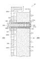
熱硬化炉4は、炉内が高温化されるため、炉壁には高い断熱性が要求される。炉壁は、その厚さを厚くするほど断熱性が高くなるが、厚さの増大に応じて設備が大型化するという課題を有する。熱硬化炉4の炉壁24は、厚さが薄くかつ断熱性能が高い構造を有している。具体的には、図5に要部を拡大して断面で示すように、炉内壁241と炉外壁242との間に薄肉で高効率断熱性の断熱材243を介在させて、炉外壁242と断熱材243との間に、空気層を形成するための隙間を設けた構造を有している。そして、炉内壁241を断熱材243に締結固定する締結部品を介して炉内壁241から炉外壁242への熱伝導を封止するため、炉外壁242と断熱材243との間を断熱性の締結部品で固定する構造を有している。
<Composition of furnace wall>
Since the inside of the thermosetting furnace 4 is heated to a high temperature, the furnace wall is required to have high heat insulating properties. The thicker the thickness of the furnace wall, the higher the heat insulating property, but there is a problem that the equipment becomes larger as the thickness increases. The
炉壁24は、例えばSUS板により構成される炉内壁241と、ポリカーボネート板により構成される炉外壁242と、これらの間に配置された高効率断熱性の断熱材243とを有している。断熱材243には、貫通孔243aが設けられており、貫通孔243aの内部にナット244が装着されている。炉内壁241と炉外壁242には、それぞれナット244に対応する位置にボルト挿通穴241a、242aが設けられており、ナット244の軸方向両側からそれぞれボルト245、246が挿通されてナット244に螺合され、締結されている。
The
炉外壁242と断熱材243との間には、空気層を設けるための隙間が設けられている。隙間は、炉外壁242と断熱材243との間に、例えば断熱性の樹脂製材料からなる断熱スペーサ247を介在させることによって形成されている。断熱スペーサ247及び空気層は、断熱材243から炉外壁242への熱伝導を抑制し、炉壁24の断熱性を向上させることができる。また、炉外壁242には、エア循環用のスリット242bが設けられている。図5に矢印で示すように、炉外壁242と断熱材243との間の隙間には、煙突効果によって、スリット242bから空気が取り込まれ、炉外壁242の端部から排出される空気の流れ(図中細矢印で示す)が形成される。したがって、断熱材243から炉外壁242への熱伝導をさらに抑制し、炉壁24の断熱性を飛躍的に向上させることができる。
A gap for providing an air layer is provided between the furnace
また、炉外壁242をナット244に締結するボルト246は、ナット244との間に断熱カラー248が介在され、さらに、ボルト246のボルトヘッドと炉外壁242との間に断熱ワッシャ249が介在されている。断熱カラー248と断熱ワッシャ249は、例えば断熱性の高い樹脂製材料により構成されており、ボルト245とナット244を介して炉内から伝達される熱エネルギ(図中太矢印で示す)を遮断して、炉外壁242に伝達されるのを防ぐことができる。このように本実施形態の炉壁24は、断熱性能の高い構造を有しているので、断熱材243の厚さを従来よりも薄くすることができる。したがって、設備構成の小型化及び簡略化が可能となる。
Further, in the
<ノズルの構成>
ノズル22は、図3に示すように、加熱室20の天井に設けられている。ノズル22は、整流室221と、整流室221の下方に設けられて胴体部11の表面に熱風を噴射する一体の噴射口222とを有する。整流室221は、タンク容器10の中心軸Lの方向に沿って延びる扁平箱状の第1整流室221Aと、第1整流室221Aの両端部で折曲されて対をなして互いに平行に延びる扁平箱状の第2整流室221Bを有している。
<Nozzle configuration>
As shown in FIG. 3, the
そして、図6に示すように、第1整流室221Aと第2整流室221Bの上面には、加熱室20の天井に取り付けた状態で炉壁24の貫通孔24a、24bを介して吸排気ボックス26の吸気路261と連通する連通孔223A、223Bが複数設けられている。第1整流室221Aと第2整流室221Bは、連通孔223A、223Bから流入する熱風を整流して噴射口222に供給する。
Then, as shown in FIG. 6, on the upper surfaces of the
噴射口222は、第1整流室221Aの下方に設けられて第1整流室221Aで整流された熱風を胴体部11の表面に噴射する第1噴射口222Aと、第2整流室221Bの下方に設けられて第2整流室221Bで整流された熱風をドーム部12の表面に噴射する第2噴射口222Bを有している。
The
第1噴射口222Aと第2噴射口222Bは、スリット形状を呈している。第1噴射口222Aは、第1整流室221Aの長手方向に沿って延設され、第2噴射口222Bは、第2整流室221Bの長手方向に沿って延設されている。第1噴射口222Aは、タンク容器10の胴体部11に対応するように該胴体部11の形状に沿って配置されており、胴体部11の表面に熱風を噴射する。第2噴射口222Bは、タンク容器10のドーム部12に対応するように該ドーム部12の形状に沿って配置されており、ドーム部12の接線方向からドーム部12の表面に熱風を噴射する。第1噴射口222A、第2噴射口222Bを用いることによって、胴体部11の表面とドーム部12の表面をそれぞれムラなく加熱することができる。
The
第1噴射口222A及び第2噴射口222Bは、タンク容器10に対して上下方向(すなわち、タンク容器10の中心軸Lの鉛直方向)、左右方向(すなわち、タンク容器10の中心軸L方向)及び前後方向に移動可能に構成されることが好ましく、更に噴射角度が変更可能に構成されることがより好ましい。かかる構成によれば、タンク容器10の形状変化に柔軟に対応することができる。
The
本実施形態において、タンク容器10の中心軸L方向から見たとき、第1噴射口222Aは、タンク容器10の中心軸Lの鉛直方向に対してずれた位置に配置されている。具体的には、図4に示すように、第1噴射口222Aは、タンク容器10の中心軸Lの鉛直方向に対して左側にずれた位置に配置されている。換言すれば、第1噴射口222Aは、タンク容器10の中心より左側に偏心する。ここで、第1噴射口222Aは、タンク容器10の胴体部11の接線方向から熱風を噴射するように、中心軸Lの鉛直方向に対して胴体部11の半径と同じ距離で左側にずれた位置に配置されても良い。
In the present embodiment, when viewed from the central axis L direction of the
また、本実施形態において、回転装置21は、第1噴射口222Aからの熱風の噴射方向と逆向きにタンク容器10を回転させるように設定されている。具体的には、図4に示すように、第1噴射口222Aがタンク容器10の中心軸Lの鉛直方向に対して左側にずれた位置に配置されるので、第1噴射口222Aから噴射される熱風は、タンク容器10の表面に沿って反時計回り(矢印F1参照)に流れる。これに対し、タンク容器10は回転装置21によって時計回り(白塗り矢印F2参照)に回転される。
Further, in the present embodiment, the rotating
<吸排気ボックスの構成>
吸排気ボックス26は、第1昇温室20A、第2昇温室20B、均熱室20Cに対応してそれぞれ設けられている。そして、各吸排気ボックス26は、吸気路261と排気路262が一体化された構造を有している。例えば従来は、温風を循環させるために熱硬化炉に吸気ダクト及び排気ダクトを別々に接続していたが、そのような構造は、大きなスペースを占有し、ダクト長が長くなるため、吸排気抵抗が大きくなり、また、放熱によるエネルギーロスにもつながっていた。これに対して、吸排気ボックス26は、吸気路261と排気路262が一体化された構造を有しているので、省スペース化と部品の簡素化ができると共に、ダクト長が短くなるため、吸排気抵抗が小さくなり、かつ、放熱によるエネルギーロスも小さくなる。
<Structure of intake / exhaust box>
The intake /
各吸排気ボックス26には、プラグヒータ263(図1を参照)がそれぞれ内蔵されており、吸気路261を通過して第1昇温室20A、第2昇温室20B、均熱室20Cに供給されるガスをそれぞれ加熱して加熱室20毎に予め設定された温度に調整する。第1昇温室20A、第2昇温室20B、均熱室20Cの各ノズル22には、噴射される熱風の温度を検出する温度センサが設けられており、温度センサの検出信号に基づいて、各プラグヒータ263の加熱量を制御するフィードバック制御が行われる。
Each intake /
吸排気ボックス26は、図7に示すように、底面26aに吸気口264a、264bと排気口264cが設けられている。吸気口264aは、加熱室20の天井を貫通する貫通孔24a及び第1整流室221Aの連通孔223Aを介して吸排気ボックス26の吸気路261とノズル22の整流室221との間を連通する位置に開口し、吸気口264bは、加熱室20の天井を貫通する貫通孔24b(図3を参照)及び第2整流室221Bの連通孔223Bを介して吸排気ボックス26の吸気路261と加熱室20との間を連通する位置に開口している。そして、排気口264cは、加熱室20の天井を貫通する貫通孔24cを介して吸排気ボックス26の排気路262と熱硬化炉4の炉内との間を連通する位置に開口している。したがって、吸気口264を通過して吸排気ボックス26の吸気路261からノズル22の整流室221に熱風を供給することができ、また、排気口264cを通過して加熱室20内のガスを吸排気ボックス26の排気路262に排出させることができる。
As shown in FIG. 7, the intake /
吸排気ボックス26内には、風量調整用ダンパー266が設けられている。風量調整用ダンパー266は、整流室221に連通する吸気口264aの開口面積を変更してノズル22に供給されるガスの供給量を調整する開閉式の第1吸気ダンパー266aと、加熱室20に連通する吸気口264bの開口面積を変更して加熱室20に直接供給されるガスの供給量を調整する開閉式の第2吸気ダンパー266bと、熱硬化炉4の炉内に連通する排気口264cの開口面積を変更して熱硬化炉4の加熱室20から排出されるガスの排出量を調整する開閉式の排気ダンパー266cを有する。
A
風量調整用ダンパー266は、例えば吸排気ボックス26の底面26aに沿ってシャッターがスライド移動して吸気口264a、264b、排気口264cをそれぞれ独立して開閉するシャッター構造を有しており、制御装置によって開閉制御される。制御装置は、熱硬化炉4の炉内圧力を計測する圧力計測センサからの信号に基づいて炉内圧力のフィードバック制御を行う。制御装置は、熱硬化炉4の炉内圧力が所定値よりも正圧の場合には排気ダンパー266cを制御して排気口264cの開口面積を広げ、所定値よりも負圧の場合には吸気ダンパー266a、266bを制御して吸気口264a、264bの開口面積を広げる制御を行う。したがって、熱風の吸排気バランスを調整して、炉内温度を安定化させ、タンク容器10の硬化品質の安定化を図ることができる。
The air
<冷却炉の構成>
冷却炉5の徐冷室31と急冷室32には、熱硬化炉4の加熱室20と同様の回転装置がそれぞれ配置されており、搬送装置3によって搬送されるタンク容器10をその中心軸回りに回転させるようになっている。ノズル15は、徐冷室31で回転装置によって回転されるタンク容器10の表面に高温ガスの熱風又は常温の風を吹き付ける。ノズル15から噴射される熱風は、例えばガス供給機6で発生された基準ガス温度を有する高温ガスの熱風であって、熱硬化炉4においてノズル22から噴射される高温ガスの温度よりも低い温度を有する。したがって、徐冷室31において、熱硬化炉4から搬送されてきたタンク容器10の温度を徐々に低下させることができる。ノズル15は、熱風の代わりに常温の風を吹き付けてもよい。常温の風も、熱硬化炉4においてノズル22から噴射される高温ガスの温度よりも低い温度を有するので、徐冷室31において、熱硬化炉4から搬送されてきたタンク容器10の温度を徐々に低下させることができる。
<Cooling reactor configuration>
Rotating devices similar to those of the
急冷室32のノズル16は、急冷室32で回転装置によって回転されるタンク容器10の表面に低温の冷媒を吹き付ける。ノズル16から噴射される冷媒は、例えば常温の空気や液体であり、徐冷室31でノズル15から噴射される高温ガスの温度よりも低い温度を有する。したがって、急冷室32において、徐冷室31から搬送されてきたタンク容器10の温度を急激に低下させることができる。
The
<燃料タンクの製造工程>
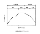
次に、上記構成の燃料タンク製造装置1を用いた燃料タンクの製造工程について説明する。図8は、熱硬化炉の温度プロファイルの一例を示すグラフ、図9は、燃料タンクの製造工程を説明するフローチャートである。なお、以下に示す燃料タンク製造装置1の動作は、図示していない制御装置の制御によって実行される。
<Fuel tank manufacturing process>
Next, a fuel tank manufacturing process using the fuel tank manufacturing apparatus 1 having the above configuration will be described. FIG. 8 is a graph showing an example of a temperature profile of a thermosetting furnace, and FIG. 9 is a flowchart illustrating a manufacturing process of a fuel tank. The operation of the fuel tank manufacturing apparatus 1 shown below is executed by the control of a control apparatus (not shown).
燃料タンク製造装置1を用いた燃料タンクの製造工程では、タンク容器10に対して熱硬化性樹脂の複雑な硬化反応に対応した温度及びタイミングで加熱及び冷却が行われる。燃料タンクの製造工程は、図8に示すように、加熱工程と冷却工程とを有している。加熱工程は、筐体2の上段の熱硬化炉4で行われ、冷却工程は、筐体2の下段の冷却炉5で行われる。
In the fuel tank manufacturing process using the fuel tank manufacturing apparatus 1, the
加熱工程は、所定速度で温度を上昇させる昇温工程と、所定時間一定温度に保つ均熱工程を含み、冷却工程は、所定速度で温度を低下させる徐冷工程と、徐冷工程よりも速い速度で温度を低下させる急冷工程を含む。本実施形態では、昇温工程においてステップ状に温度を上昇させている。例えば生産性を向上させるために、昇温工程において急激に加熱温度を上昇させると、熱硬化性樹脂が脆くなり、燃料タンクとして所期の性能を発揮することが困難になる場合がある。したがって、熱硬化性樹脂の硬化反応に対応した加熱条件に適合するように、本実施形態では、昇温工程においてステップ状に温度を上昇させて、熱硬化性樹脂が脆くなるのを防ぎ、所期の性能を発揮させることができるようにしている。 The heating step includes a temperature raising step of raising the temperature at a predetermined rate and a soaking step of keeping the temperature constant for a predetermined time, and the cooling step is faster than a slow cooling step of lowering the temperature at a predetermined rate and a slow cooling step. Includes a quenching step that reduces the temperature at a rate. In the present embodiment, the temperature is raised stepwise in the temperature raising step. For example, if the heating temperature is rapidly raised in the temperature raising step in order to improve productivity, the thermosetting resin becomes brittle, and it may be difficult to exhibit the desired performance as a fuel tank. Therefore, in order to meet the heating conditions corresponding to the curing reaction of the thermosetting resin, in the present embodiment, the temperature is raised stepwise in the temperature raising step to prevent the thermosetting resin from becoming brittle. We are trying to bring out the performance of the period.
燃料タンクの製造工程は、図9に示すように、まず、硬化前品である熱硬化性樹脂が未硬化状態のタンク容器10を筐体2の開口部2aから筐体2の内部に搬入する(S101)。そして、ガス供給機6で基準ガス温度の熱風を発生させ、熱硬化炉4に供給し、熱硬化炉4の炉内温度を基準ガス温度まで昇温させる(S102)。そして、タンク容器10を熱硬化炉4内の第1昇温室20Aに搬送する(S103)。開閉扉25Aは、タンク容器10を熱硬化炉4内に搬送するタイミングで開かれ、タンク容器10が第1昇温室20Aに配置されたタイミングで閉じられる。したがって、熱硬化炉4内の炉内温度の低下を抑制して炉内温度を安定させることができる。
In the fuel tank manufacturing process, as shown in FIG. 9, first, the
タンク容器10は、第1昇温室20Aに搬送されると、第1昇温室20Aで回転装置21によって中心軸回りに回転される。そして、第1昇温室20Aに取り付けられている吸排気ボックス26内のプラグヒータ263によって、吸排気ボックス26内の吸気路261を通過する高温ガスが加熱されて、基準ガス温度よりも高温の第1ガス温度まで昇温されたガスが、第1昇温室20Aのノズル22からタンク容器10の表面に向かって噴射される(S104)。タンク容器10は、回転装置21によって中心軸回りに回転されているので、第1昇温室20Aのノズル22からタンク容器10の表面全体に第1ガス温度のガスの熱風が吹き付けられ、タンク容器10は、全体が均一に加熱される。
When the
タンク容器10は、第1昇温室20Aのノズル22から噴射される熱風によって所定速度で昇温され、第1のワーク温度まで加熱されると、そのまま所定時間の間、その第1のワーク温度に保持される(図8を参照)。そして、第1のワーク温度からステップ状に昇温させるべく、第1昇温室20Aから第2昇温室20Bに搬送される(S105)。
The temperature of the
タンク容器10は、第2昇温室20Bで回転装置21によって中心軸回りに回転される。そして、第2昇温室20Bに取り付けられている吸排気ボックス26内のプラグヒータ263によって、吸排気ボックス26内の吸気路261を通過する高温ガスが加熱されて、第1ガス温度よりも高温の第2ガス温度まで昇温されたガスが、第2昇温室20Bのノズル22からタンク容器10の表面に向かって噴射される(S106)。タンク容器10は、回転装置21によって中心軸回りに回転されているので、第2昇温室20Bのノズル22からタンク容器10の表面全体に第2ガス温度のガスの熱風が吹き付けられ、タンク容器10は、全体が均一に加熱される。
The
タンク容器10は、第2昇温室20Bのノズル22から噴射される熱風によって所定速度で昇温され、第2のワーク温度まで加熱される。したがって、タンク容器10は、第1のワーク温度から第2のワーク温度まで2段階に分けてステップ状に昇温される(図8の昇温工程を参照)。
The
タンク容器10は、第2のワーク温度まで加熱されると、第2昇温室20Bから均熱室20Cに搬送され(S107)、均熱室20Cで回転装置21によって中心軸回りに回転される。そして、均熱室20Cに取り付けられている吸排気ボックス26内のプラグヒータ263によって、吸排気ボックス26内の吸気路261を通過する高温ガスが加熱されて、第1ガス温度と第2ガス温度の間の温度である第3ガス温度まで昇温されたガスが、均熱室20Cのノズル22からタンク容器10の表面に向かって噴射される(S108)。タンク容器10は、回転装置21によって中心軸回りに回転されているので、均熱室20Cのノズル22からタンク容器10の表面全体に熱風が吹き付けられ、タンク容器10は、全体が均一に加熱される。タンク容器10は、均熱室20Cのノズル22から噴射される熱風によって第3のワーク温度に保持される(均熱工程)。第3のワーク温度及び保持時間は、熱硬化性樹脂の硬化反応に対応した加熱条件に適合するように、熱硬化性樹脂の熱硬化特性に応じて設定される。
When the
そして、所定時間経過後に、均熱室20Cから冷却炉5の徐冷室31に搬送され(S109)、徐冷室31で回転装置21によって中心軸回りに回転される。開閉扉25Bは、タンク容器10を熱硬化炉4から冷却炉5に搬送するタイミングで開かれ、タンク容器10が徐冷室31に配置されたタイミングで閉じられるので、熱硬化炉4内の炉内温度の低下を抑制できる。
Then, after a lapse of a predetermined time, the
タンク容器10が徐冷室31に配置されると、ガス供給機6からノズル15に基準ガス温度の熱風又は常温の風が供給され、ノズル15からタンク容器10の表面に噴射される。タンク容器10は、回転装置21によって中心軸回りに回転されているので、徐冷室31のノズル15からタンク容器10の表面全体に基準ガス温度の熱風が吹き付けられ、全体が均一に徐冷される。タンク容器10は、徐冷室31のノズル15から噴射される基準ガス温度の熱風又は常温の風によって所定速度で温度が低下する(徐冷工程)。そして、第4のワーク温度まで低下されると、徐冷室31から急冷室32に搬送され(S110)、急冷室32で回転装置21によって中心軸回りに回転される。
When the
タンク容器10が急冷室32に配置されると、急冷室32のノズル16からタンク容器10の表面に基準ガス温度よりも低温の冷媒が噴射される。タンク容器10は、回転装置21によって中心軸回りに回転されているので、急冷室32のノズル16からタンク容器10の表面全体に低温の冷媒が吹き付けられ、全体が均一に冷却される。タンク容器10は、急冷室32のノズル16から噴射される低温の冷媒によって所定速度で冷却される(急冷工程)。冷却工程におけるタンク容器10の温度の低下速度は、熱硬化性樹脂の硬化反応に対応した条件に適合するように、熱硬化性樹脂の熱硬化特性に応じて設定される。急冷工程の方が徐冷工程よりも速くなるように設定されている。そして、所定温度まで低下されると、冷却炉5から炉外に搬送され、筐体2の開口部2aから搬出される(S111)。
燃料タンク製造装置1では、以上の工程が繰り返されて、複数のタンク容器10が連続して硬化される。
When the
In the fuel tank manufacturing apparatus 1, the above steps are repeated to continuously cure the plurality of
<作用効果>
燃料タンク製造装置1は、熱硬化性樹脂の複雑な硬化反応に対応した連続硬化炉にするために、各加熱室20に、タンク容器10の近傍でタンク容器10を直接加熱できるタンク形状に沿ったノズル22を設置し、各加熱室20において熱風をタンク容器10に直接吹き付ける構造を有する。そして、各吸排気ボックス26にプラグヒータ263をそれぞれ内蔵して、各加熱室20毎にノズル22から噴射されるガスの温度のフィードバック制御を行う。
<Effect>
The fuel tank manufacturing apparatus 1 follows a tank shape capable of directly heating the
したがって、隣接する加熱室20の温度の影響が小さく、各加熱室20においてタンク容器10を加熱する温度を正確に制御できる。そして、1台のガス供給機6で各加熱室毎にノズルから噴射されるガスの温度を容易に異なった温度に制御できる。したがって、各加熱室毎に温度を区分けするために各加熱室の間を開閉する開閉扉を省略することができ、燃料タンク製造装置1の製造コストを低減し、かつ、構造を簡略化でき、設備集約でき、また、開閉扉の開閉による温度バラツキがなく、硬化品質の安定化が図られる。
Therefore, the influence of the temperature of the
また、炉壁24に薄肉で高効率断熱性の断熱材243を使用すると共に、炉外壁242と断熱材243との間を断熱性の締結部品で固定し、さらに、炉外壁242と断熱材243との間に空気層を設け、空気層に連続するエア循環用のスリット242bを炉外壁242に設けている。したがって、断熱性能を低下させることなく、炉壁24の厚さを極めて薄くすることができ、設備のサイズをよりコンパクト化することができる。
Further, a thin-walled and highly efficient
燃料タンク製造装置1は、吸気路261と排気路262を有する吸排気ボックス26を熱硬化炉4の各加熱室20と一体化すると共に、その内部に風量調整用ダンパーを設けている。したがって、省スペースと部品の簡素化ができると共に、熱風の吸排気バランスを調整することが可能となり、炉内温度を安定化させ、タンク容器10の硬化品質の安定化を図ることができる。
In the fuel tank manufacturing apparatus 1, an intake /
以上、本発明の実施形態について詳述したが、本発明は、上述の実施形態に限定されるものではなく、特許請求の範囲に記載された本発明の精神を逸脱しない範囲で、種々の設計変更を行うことができるものである。 Although the embodiments of the present invention have been described in detail above, the present invention is not limited to the above-described embodiments, and various designs are designed without departing from the spirit of the present invention described in the claims. You can make changes.
1 燃料タンク製造装置
2 筐体
3 搬送装置
4 熱硬化炉
5 冷却炉
6 ガス供給機
7 ガス排出機
8 吸気ダクト
9 排気ダクト
10 タンク容器
11 胴体部
12 ドーム部
13 軸支シャフト
20 加熱室
20A 第1昇温室
20B 第2昇温室
20C 均熱室
21 回転装置
210 軸受部材
211 回転モータ
22 ノズル
221 整流室
222 噴射口
24 炉壁
25A、25B 開閉扉
26 吸排気ボックス
261 吸気路
262 排気路
264a、264b 吸気口
264c 排気口
31 徐冷室
32 急冷室
L 中心軸
1 Fuel
Claims (4)
タンク容器を搬送する搬送装置と、
搬送途中で前記タンク容器を加熱する複数の加熱室と、
該複数の加熱室よりも前記搬送装置の搬送方向下流位置で前記タンク容器を冷却する冷却室と、
前記複数の加熱室にガスを供給するガス供給機と、
前記複数の加熱室において前記ガス供給機から供給されたガスを前記タンク容器の表面に噴射する複数のノズルと、
前記ガス供給機と前記複数のノズルとの間で前記ガスを加熱する複数のヒータと、
を備えることを特徴とする燃料タンク製造装置。 A fuel tank manufacturing apparatus that heats a tank container in which fibers impregnated with a thermosetting resin are wound on its surface to heat-cure the thermosetting resin.
A transport device that transports tank containers and
A plurality of heating chambers for heating the tank container during transportation,
A cooling chamber that cools the tank container at a position downstream of the plurality of heating chambers in the transport direction of the transport device.
A gas supply machine that supplies gas to the plurality of heating chambers,
A plurality of nozzles for injecting gas supplied from the gas supply machine onto the surface of the tank container in the plurality of heating chambers.
A plurality of heaters for heating the gas between the gas supply machine and the plurality of nozzles,
A fuel tank manufacturing apparatus characterized by being equipped with.
前記複数のヒータは、前記ノズルから噴射されるガスの温度を第2昇温室、均熱室、第1昇温室の順番で低くすることを特徴とする請求項1に記載の燃料タンク製造装置。 The plurality of heating chambers include a first heating chamber, a second heating chamber, and a soaking chamber, which are sequentially arranged from the upstream side to the downstream side in the transport direction of the transport device.
The fuel tank manufacturing apparatus according to claim 1, wherein the plurality of heaters lower the temperature of the gas injected from the nozzle in the order of the second heating chamber, the soaking chamber, and the first heating chamber.
前記加熱室の圧力を計測する圧力計測センサと、
前記圧力計測センサからの信号に基づいて前記加熱室の圧力のフィードバック制御を行う制御装置と、を備え、
該各吸排気ボックスは、
前記ノズルに連通する吸気口の開口面積を変更して前記ノズルに供給されるガスの供給量を調整する吸気ダンパーと、
前記加熱室に開口する排気口の開口面積を変更して前記加熱室から排出されるガスの排出量を調整する排気ダンパーと、を有し、
前記制御装置は、前記加熱室の圧力が所定値よりも正圧の場合には前記排気ダンパーを制御して前記排気口の開口面積を広げ、前記所定値よりも負圧の場合には前記吸気ダンパーを制御して前記吸気口の開口面積を広げる制御を行うことを特徴とする請求項1または請求項2に記載の燃料タンク製造装置。 Intake and exhaust boxes provided corresponding to the plurality of heating chambers , and
A pressure measurement sensor that measures the pressure in the heating chamber and
A control device that performs feedback control of the pressure in the heating chamber based on a signal from the pressure measurement sensor is provided.
Each intake / exhaust box is
An intake damper that adjusts the supply amount of gas supplied to the nozzle by changing the opening area of the intake port that communicates with the nozzle.
It has an exhaust damper that adjusts the amount of gas discharged from the heating chamber by changing the opening area of the exhaust port that opens to the heating chamber .
The control device controls the exhaust damper when the pressure in the heating chamber is more positive than a predetermined value to widen the opening area of the exhaust port, and when the pressure is negative than the predetermined value, the intake air is taken. fuel tank manufacturing apparatus according to claim 1 or claim 2, wherein the performing control to widen the opening area of the air inlet and controls the damper.
前記複数の加熱室には、前記タンク容器を該タンク容器の中心軸回りに回転させる回転部が設けられており、
前記複数のノズルは、前記胴体部の表面にガスを噴射する第1噴射口と、前記ドーム部の接線方向から該ドーム部の表面にガスを噴射する第2噴射口とを有することを特徴とする請求項1から請求項3のいずれか一項に記載の燃料タンク製造装置。 The tank container has a cylindrical body portion and dome portions provided at both ends of the body portion.
The plurality of heating chambers are provided with a rotating portion for rotating the tank container around the central axis of the tank container.
The plurality of nozzles are characterized by having a first injection port for injecting gas onto the surface of the body portion and a second injection port for injecting gas onto the surface of the dome portion from the tangential direction of the dome portion. The fuel tank manufacturing apparatus according to any one of claims 1 to 3.
Priority Applications (3)
| Application Number | Priority Date | Filing Date | Title |
|---|---|---|---|
| JP2017099727A JP6769923B2 (en) | 2017-05-19 | 2017-05-19 | Fuel tank manufacturing equipment |
| US15/969,074 US10792845B2 (en) | 2017-05-19 | 2018-05-02 | Fuel tank producing apparatus |
| DE102018111237.8A DE102018111237A1 (en) | 2017-05-19 | 2018-05-09 | Fuel tank manufacturing apparatus |
Applications Claiming Priority (1)
| Application Number | Priority Date | Filing Date | Title |
|---|---|---|---|
| JP2017099727A JP6769923B2 (en) | 2017-05-19 | 2017-05-19 | Fuel tank manufacturing equipment |
Publications (2)
| Publication Number | Publication Date |
|---|---|
| JP2018192742A JP2018192742A (en) | 2018-12-06 |
| JP6769923B2 true JP6769923B2 (en) | 2020-10-14 |
Family
ID=64270341
Family Applications (1)
| Application Number | Title | Priority Date | Filing Date |
|---|---|---|---|
| JP2017099727A Active JP6769923B2 (en) | 2017-05-19 | 2017-05-19 | Fuel tank manufacturing equipment |
Country Status (3)
| Country | Link |
|---|---|
| US (1) | US10792845B2 (en) |
| JP (1) | JP6769923B2 (en) |
| DE (1) | DE102018111237A1 (en) |
Families Citing this family (4)
| Publication number | Priority date | Publication date | Assignee | Title |
|---|---|---|---|---|
| DE102018127207A1 (en) * | 2018-10-31 | 2020-04-30 | Dbk David + Baader Gmbh | Oven for carbon fiber-wrapped tank |
| JP7264075B2 (en) | 2020-01-30 | 2023-04-25 | トヨタ自動車株式会社 | High pressure tank manufacturing equipment |
| KR102351446B1 (en) * | 2021-06-21 | 2022-01-17 | (주)탑솔루션 | A rotating apparatus for hardening hydrogen fuel tank |
| CN113478707B (en) * | 2021-07-07 | 2023-08-22 | 江阴市富仁高科股份有限公司 | Centralized curing device and curing method for carbon fiber winding hydrogen storage tank |
Family Cites Families (16)
| Publication number | Priority date | Publication date | Assignee | Title |
|---|---|---|---|---|
| US3282757A (en) * | 1962-12-14 | 1966-11-01 | Structural Fibers | Method of making a filament reinforced pressure vessel |
| DE3920573A1 (en) * | 1989-06-23 | 1991-01-10 | Ver Glaswerke Gmbh | COOLING CHANNEL FOR CONTROLLED COOLING OF THEN GLASS PANELS |
| JPH0739483Y2 (en) * | 1990-11-15 | 1995-09-13 | 千住金属工業株式会社 | Reflow furnace |
| FI86406C (en) * | 1991-01-11 | 1992-08-25 | Tamglass Oy | Device for thermosetting of glass sheets |
| US6131411A (en) * | 1998-12-21 | 2000-10-17 | Glasstech, Inc. | Method and furnace for heating glass sheets |
| US7975603B1 (en) * | 2002-12-04 | 2011-07-12 | Alkar-Rapidpak-Mp Equipment, Inc. | Food processing system |
| JP2005049072A (en) | 2003-07-31 | 2005-02-24 | Kyocera Kinseki Corp | Tunnel kiln |
| US7316080B1 (en) * | 2004-05-27 | 2008-01-08 | Solution Dynamics, Llc | Methodology and apparatus to reduce fuel consumption in conveyor dryers and ovens |
| DE102006009388B4 (en) | 2006-03-01 | 2009-02-26 | Audi Ag | Apparatus for siliconising carbonaceous materials and method practicable therein |
| GB0706144D0 (en) | 2007-03-30 | 2007-05-09 | Knauf Insulation Ltd | Curing oven for mineral wool mat |
| WO2008144427A1 (en) * | 2007-05-18 | 2008-11-27 | Coopervision International Holding Company, Lp | Thermal curing methods and systems for forming contact lenses |
| US8220130B2 (en) * | 2007-07-25 | 2012-07-17 | Plasteel International, Inc. | Method for manufacturing an underground storage tank for flammable and combustible liquids |
| ITMI20110401A1 (en) * | 2011-03-14 | 2012-09-15 | Petroceramics S P A | METHOD FOR INFILTRATION OF A POROUS MATERIAL WITH A SECOND MATERIAL AND ITS PLANT |
| US10023322B2 (en) * | 2012-01-30 | 2018-07-17 | Neal Keefer | Molded fuel tank and method of manufacturing the same |
| JP5775501B2 (en) * | 2012-10-01 | 2015-09-09 | トヨタ自動車株式会社 | Textile holding device, high-pressure gas tank manufacturing device, and tank manufacturing method |
| JP5952953B1 (en) | 2015-12-02 | 2016-07-13 | 株式会社平田精機 | Bending mechanism for treatment instrument and treatment instrument |
-
2017
- 2017-05-19 JP JP2017099727A patent/JP6769923B2/en active Active
-
2018
- 2018-05-02 US US15/969,074 patent/US10792845B2/en active Active
- 2018-05-09 DE DE102018111237.8A patent/DE102018111237A1/en not_active Withdrawn
Also Published As
| Publication number | Publication date |
|---|---|
| JP2018192742A (en) | 2018-12-06 |
| US10792845B2 (en) | 2020-10-06 |
| US20180333900A1 (en) | 2018-11-22 |
| DE102018111237A1 (en) | 2018-11-22 |
Similar Documents
| Publication | Publication Date | Title |
|---|---|---|
| JP6769923B2 (en) | Fuel tank manufacturing equipment | |
| US20120171632A1 (en) | Device and treatment chamber for thermally treating substrates | |
| JP6791797B2 (en) | Fuel tank manufacturing equipment | |
| US20010051323A1 (en) | Convection-type brazing method and its apparatus for metal workpieces | |
| US8105529B1 (en) | Heated injection molding system and method | |
| CN109863823B (en) | Method and device for producing a molded part having a semifinished product | |
| US20130167488A1 (en) | Hot wind supplying apparatus for packaging product | |
| JP2007084870A (en) | Carburizing treatment apparatus and method | |
| CN102174668B (en) | Retort furnace for heat treating metal workpieces | |
| CN104402249B (en) | Automobile glass heating method and heating device thereof | |
| MX2014015603A (en) | Heating furnace. | |
| US10647048B2 (en) | Method and device for tempering preforms | |
| KR20100131129A (en) | Sintering furnace or heat treatment furnace enhanced by the module of uniformizing heat flux and gas flow at low temperature zone and accelerating cooldown speed | |
| US6338623B1 (en) | Rotational molding oven | |
| KR20090025872A (en) | Device of producing thin film heating material and producing method using the same | |
| CN109661551A (en) | Annealing device | |
| JP6769908B2 (en) | Fuel tank manufacturing equipment | |
| JP2000108123A (en) | Hot runner device for molding preform | |
| JP3753570B2 (en) | Preheating apparatus and preheating method | |
| WO2023053733A1 (en) | Heat shrinking device | |
| EP3205468B1 (en) | Air impingement device, system and method for thermal processing and consolidation | |
| US11597138B2 (en) | High-pressure tank producing apparatus | |
| CN116399128B (en) | Uniform atmosphere adjusting system for sintering furnace | |
| CN110671917B (en) | Meshbelt drying device | |
| JP2016176661A (en) | Firing furnace and coating method |
Legal Events
| Date | Code | Title | Description |
|---|---|---|---|
| A621 | Written request for application examination |
Free format text: JAPANESE INTERMEDIATE CODE: A621 Effective date: 20190906 |
|
| A977 | Report on retrieval |
Free format text: JAPANESE INTERMEDIATE CODE: A971007 Effective date: 20200520 |
|
| A131 | Notification of reasons for refusal |
Free format text: JAPANESE INTERMEDIATE CODE: A131 Effective date: 20200623 |
|
| A521 | Request for written amendment filed |
Free format text: JAPANESE INTERMEDIATE CODE: A523 Effective date: 20200819 |
|
| TRDD | Decision of grant or rejection written | ||
| A01 | Written decision to grant a patent or to grant a registration (utility model) |
Free format text: JAPANESE INTERMEDIATE CODE: A01 Effective date: 20200901 |
|
| A61 | First payment of annual fees (during grant procedure) |
Free format text: JAPANESE INTERMEDIATE CODE: A61 Effective date: 20200924 |
|
| R151 | Written notification of patent or utility model registration |
Ref document number: 6769923 Country of ref document: JP Free format text: JAPANESE INTERMEDIATE CODE: R151 |
|
| R250 | Receipt of annual fees |
Free format text: JAPANESE INTERMEDIATE CODE: R250 |