JP6767486B2 - Medical holding arm with annular LED display means - Google Patents
Medical holding arm with annular LED display means Download PDFInfo
- Publication number
- JP6767486B2 JP6767486B2 JP2018527011A JP2018527011A JP6767486B2 JP 6767486 B2 JP6767486 B2 JP 6767486B2 JP 2018527011 A JP2018527011 A JP 2018527011A JP 2018527011 A JP2018527011 A JP 2018527011A JP 6767486 B2 JP6767486 B2 JP 6767486B2
- Authority
- JP
- Japan
- Prior art keywords
- holding device
- display unit
- joint
- state
- joints
- Prior art date
- Legal status (The legal status is an assumption and is not a legal conclusion. Google has not performed a legal analysis and makes no representation as to the accuracy of the status listed.)
- Active
Links
Images


Classifications
-
- A—HUMAN NECESSITIES
- A61—MEDICAL OR VETERINARY SCIENCE; HYGIENE
- A61B—DIAGNOSIS; SURGERY; IDENTIFICATION
- A61B90/00—Instruments, implements or accessories specially adapted for surgery or diagnosis and not covered by any of the groups A61B1/00 - A61B50/00, e.g. for luxation treatment or for protecting wound edges
- A61B90/50—Supports for surgical instruments, e.g. articulated arms
-
- A—HUMAN NECESSITIES
- A61—MEDICAL OR VETERINARY SCIENCE; HYGIENE
- A61B—DIAGNOSIS; SURGERY; IDENTIFICATION
- A61B17/00—Surgical instruments, devices or methods, e.g. tourniquets
- A61B17/02—Surgical instruments, devices or methods, e.g. tourniquets for holding wounds open; Tractors
-
- A—HUMAN NECESSITIES
- A61—MEDICAL OR VETERINARY SCIENCE; HYGIENE
- A61B—DIAGNOSIS; SURGERY; IDENTIFICATION
- A61B34/00—Computer-aided surgery; Manipulators or robots specially adapted for use in surgery
- A61B34/30—Surgical robots
-
- B—PERFORMING OPERATIONS; TRANSPORTING
- B25—HAND TOOLS; PORTABLE POWER-DRIVEN TOOLS; MANIPULATORS
- B25J—MANIPULATORS; CHAMBERS PROVIDED WITH MANIPULATION DEVICES
- B25J1/00—Manipulators positioned in space by hand
- B25J1/02—Manipulators positioned in space by hand articulated or flexible
-
- B—PERFORMING OPERATIONS; TRANSPORTING
- B25—HAND TOOLS; PORTABLE POWER-DRIVEN TOOLS; MANIPULATORS
- B25J—MANIPULATORS; CHAMBERS PROVIDED WITH MANIPULATION DEVICES
- B25J1/00—Manipulators positioned in space by hand
- B25J1/12—Manipulators positioned in space by hand having means for attachment to a support stand
-
- B—PERFORMING OPERATIONS; TRANSPORTING
- B25—HAND TOOLS; PORTABLE POWER-DRIVEN TOOLS; MANIPULATORS
- B25J—MANIPULATORS; CHAMBERS PROVIDED WITH MANIPULATION DEVICES
- B25J11/00—Manipulators not otherwise provided for
- B25J11/0005—Manipulators having means for high-level communication with users, e.g. speech generator, face recognition means
-
- B—PERFORMING OPERATIONS; TRANSPORTING
- B25—HAND TOOLS; PORTABLE POWER-DRIVEN TOOLS; MANIPULATORS
- B25J—MANIPULATORS; CHAMBERS PROVIDED WITH MANIPULATION DEVICES
- B25J11/00—Manipulators not otherwise provided for
- B25J11/005—Manipulators for mechanical processing tasks
-
- B—PERFORMING OPERATIONS; TRANSPORTING
- B25—HAND TOOLS; PORTABLE POWER-DRIVEN TOOLS; MANIPULATORS
- B25J—MANIPULATORS; CHAMBERS PROVIDED WITH MANIPULATION DEVICES
- B25J13/00—Controls for manipulators
- B25J13/02—Hand grip control means
-
- B—PERFORMING OPERATIONS; TRANSPORTING
- B25—HAND TOOLS; PORTABLE POWER-DRIVEN TOOLS; MANIPULATORS
- B25J—MANIPULATORS; CHAMBERS PROVIDED WITH MANIPULATION DEVICES
- B25J13/00—Controls for manipulators
- B25J13/08—Controls for manipulators by means of sensing devices, e.g. viewing or touching devices
- B25J13/081—Touching devices, e.g. pressure-sensitive
- B25J13/082—Grasping-force detectors
-
- B—PERFORMING OPERATIONS; TRANSPORTING
- B25—HAND TOOLS; PORTABLE POWER-DRIVEN TOOLS; MANIPULATORS
- B25J—MANIPULATORS; CHAMBERS PROVIDED WITH MANIPULATION DEVICES
- B25J13/00—Controls for manipulators
- B25J13/08—Controls for manipulators by means of sensing devices, e.g. viewing or touching devices
- B25J13/081—Touching devices, e.g. pressure-sensitive
- B25J13/084—Tactile sensors
-
- B—PERFORMING OPERATIONS; TRANSPORTING
- B25—HAND TOOLS; PORTABLE POWER-DRIVEN TOOLS; MANIPULATORS
- B25J—MANIPULATORS; CHAMBERS PROVIDED WITH MANIPULATION DEVICES
- B25J13/00—Controls for manipulators
- B25J13/08—Controls for manipulators by means of sensing devices, e.g. viewing or touching devices
- B25J13/085—Force or torque sensors
-
- B—PERFORMING OPERATIONS; TRANSPORTING
- B25—HAND TOOLS; PORTABLE POWER-DRIVEN TOOLS; MANIPULATORS
- B25J—MANIPULATORS; CHAMBERS PROVIDED WITH MANIPULATION DEVICES
- B25J19/00—Accessories fitted to manipulators, e.g. for monitoring, for viewing; Safety devices combined with or specially adapted for use in connection with manipulators
- B25J19/06—Safety devices
-
- B—PERFORMING OPERATIONS; TRANSPORTING
- B25—HAND TOOLS; PORTABLE POWER-DRIVEN TOOLS; MANIPULATORS
- B25J—MANIPULATORS; CHAMBERS PROVIDED WITH MANIPULATION DEVICES
- B25J9/00—Programme-controlled manipulators
- B25J9/06—Programme-controlled manipulators characterised by multi-articulated arms
-
- F—MECHANICAL ENGINEERING; LIGHTING; HEATING; WEAPONS; BLASTING
- F16—ENGINEERING ELEMENTS AND UNITS; GENERAL MEASURES FOR PRODUCING AND MAINTAINING EFFECTIVE FUNCTIONING OF MACHINES OR INSTALLATIONS; THERMAL INSULATION IN GENERAL
- F16M—FRAMES, CASINGS OR BEDS OF ENGINES, MACHINES OR APPARATUS, NOT SPECIFIC TO ENGINES, MACHINES OR APPARATUS PROVIDED FOR ELSEWHERE; STANDS; SUPPORTS
- F16M13/00—Other supports for positioning apparatus or articles; Means for steadying hand-held apparatus or articles
- F16M13/02—Other supports for positioning apparatus or articles; Means for steadying hand-held apparatus or articles for supporting on, or attaching to, an object, e.g. tree, gate, window-frame, cycle
- F16M13/022—Other supports for positioning apparatus or articles; Means for steadying hand-held apparatus or articles for supporting on, or attaching to, an object, e.g. tree, gate, window-frame, cycle repositionable
-
- A—HUMAN NECESSITIES
- A61—MEDICAL OR VETERINARY SCIENCE; HYGIENE
- A61B—DIAGNOSIS; SURGERY; IDENTIFICATION
- A61B17/00—Surgical instruments, devices or methods, e.g. tourniquets
- A61B2017/00017—Electrical control of surgical instruments
- A61B2017/00115—Electrical control of surgical instruments with audible or visual output
-
- A—HUMAN NECESSITIES
- A61—MEDICAL OR VETERINARY SCIENCE; HYGIENE
- A61B—DIAGNOSIS; SURGERY; IDENTIFICATION
- A61B90/00—Instruments, implements or accessories specially adapted for surgery or diagnosis and not covered by any of the groups A61B1/00 - A61B50/00, e.g. for luxation treatment or for protecting wound edges
- A61B90/08—Accessories or related features not otherwise provided for
- A61B2090/0807—Indication means
-
- A—HUMAN NECESSITIES
- A61—MEDICAL OR VETERINARY SCIENCE; HYGIENE
- A61B—DIAGNOSIS; SURGERY; IDENTIFICATION
- A61B90/00—Instruments, implements or accessories specially adapted for surgery or diagnosis and not covered by any of the groups A61B1/00 - A61B50/00, e.g. for luxation treatment or for protecting wound edges
- A61B90/36—Image-producing devices or illumination devices not otherwise provided for
- A61B90/37—Surgical systems with images on a monitor during operation
- A61B2090/372—Details of monitor hardware
-
- A—HUMAN NECESSITIES
- A61—MEDICAL OR VETERINARY SCIENCE; HYGIENE
- A61B—DIAGNOSIS; SURGERY; IDENTIFICATION
- A61B90/00—Instruments, implements or accessories specially adapted for surgery or diagnosis and not covered by any of the groups A61B1/00 - A61B50/00, e.g. for luxation treatment or for protecting wound edges
- A61B90/50—Supports for surgical instruments, e.g. articulated arms
- A61B2090/508—Supports for surgical instruments, e.g. articulated arms with releasable brake mechanisms
-
- A—HUMAN NECESSITIES
- A61—MEDICAL OR VETERINARY SCIENCE; HYGIENE
- A61B—DIAGNOSIS; SURGERY; IDENTIFICATION
- A61B90/00—Instruments, implements or accessories specially adapted for surgery or diagnosis and not covered by any of the groups A61B1/00 - A61B50/00, e.g. for luxation treatment or for protecting wound edges
- A61B90/50—Supports for surgical instruments, e.g. articulated arms
- A61B90/57—Accessory clamps
- A61B2090/571—Accessory clamps for clamping a support arm to a bed or other supports
-
- A—HUMAN NECESSITIES
- A61—MEDICAL OR VETERINARY SCIENCE; HYGIENE
- A61B—DIAGNOSIS; SURGERY; IDENTIFICATION
- A61B90/00—Instruments, implements or accessories specially adapted for surgery or diagnosis and not covered by any of the groups A61B1/00 - A61B50/00, e.g. for luxation treatment or for protecting wound edges
- A61B90/90—Identification means for patients or instruments, e.g. tags
- A61B90/94—Identification means for patients or instruments, e.g. tags coded with symbols, e.g. text
- A61B90/96—Identification means for patients or instruments, e.g. tags coded with symbols, e.g. text using barcodes
-
- B—PERFORMING OPERATIONS; TRANSPORTING
- B25—HAND TOOLS; PORTABLE POWER-DRIVEN TOOLS; MANIPULATORS
- B25J—MANIPULATORS; CHAMBERS PROVIDED WITH MANIPULATION DEVICES
- B25J18/00—Arms
- B25J18/02—Arms extensible
- B25J18/04—Arms extensible rotatable
-
- F—MECHANICAL ENGINEERING; LIGHTING; HEATING; WEAPONS; BLASTING
- F16—ENGINEERING ELEMENTS AND UNITS; GENERAL MEASURES FOR PRODUCING AND MAINTAINING EFFECTIVE FUNCTIONING OF MACHINES OR INSTALLATIONS; THERMAL INSULATION IN GENERAL
- F16M—FRAMES, CASINGS OR BEDS OF ENGINES, MACHINES OR APPARATUS, NOT SPECIFIC TO ENGINES, MACHINES OR APPARATUS PROVIDED FOR ELSEWHERE; STANDS; SUPPORTS
- F16M2200/00—Details of stands or supports
- F16M2200/02—Locking means
- F16M2200/021—Locking means for rotational movement
Description
本発明は保持装置に関し、特に保持アームおよび/またはトリポッド(tripod)に関し、医療目的のためで、特に外科のメカトロニックな補助システムを保持するおよび/または外科器具を保持するものに関する。本発明は方法にも関する。 The present invention relates to holding devices, particularly holding arms and / or tripods, for medical purposes, especially those holding surgical mechatronic assistive systems and / or holding surgical instruments. The present invention also relates to methods.
最初に特定された種類の保持装置の周りに含まれた保持アームは、従来技術から長い間によく知られ、特に手術者(執刀者)が行う静止的保持作業を緩和するように外科(手術)に利用される。このような保持アームはメカトロニックな補助システムおよび/または医療器具、例えば、マニピュレータ、内視鏡、外科用クランプなどを保持するように利用される。保持アームは最初には特に内視鏡の保持に有用性を証明された。内視鏡手術において、手術者が両手で器具を操作するとともに、補助者は操作エリアがスクリーンで見えるように内視鏡を保持する。内視鏡を長い期間に渡って保持することは非常に疲労する。上述した保持アームの利用はこの理由で増加している。 The holding arm contained around the first identified type of holding device has long been well known from the prior art and is particularly surgical (surgery) to ease the static holding work performed by the surgeon (surgeon). ) Is used. Such holding arms are utilized to hold mechatronic assistive systems and / or medical devices such as manipulators, endoscopes, surgical clamps and the like. The holding arm initially proved useful, especially for holding endoscopes. In endoscopic surgery, the surgeon operates the instrument with both hands and the assistant holds the endoscope so that the operating area is visible on the screen. Holding the endoscope for a long period of time is very tiring. The use of holding arms mentioned above is increasing for this reason.
例えば、このような保持アームは特許文献1から知られている。この文献に開示された医療目的の保持装置は連結部材および外科ツール用のホルダーを有し、ホルダーと連結部材との間に配置されたアームも有する。アームは、ホルダーおよび連結部材と連結してまた関節を介して隣接するアームと連結し、選択的に関節を固定するまたは解放するために空気圧作動式装置と過度に結合されることができる。当該空気圧作動式装置は、関節にブレーキ力を加える機械バネの動作によって関節を固定し空気圧でバネの力に対抗する関節解放モードに切り替えることができる。バルブが開放可能なアクチュエータはアームの遠位端部に設けられているため、アームの分離した複数の関節が調整可能である。アクチュエータが解放されたとき、バルブが再び閉合し、よって、関節を固定する。この保持アームの欠点の1つは全ての関節が同時に開放され、それを原因として定位が困難なことである。 For example, such a holding arm is known from Patent Document 1. The medical holding device disclosed in this document has a connecting member and a holder for a surgical tool, and also has an arm disposed between the holder and the connecting member. The arm can be connected to the holder and connecting member and also to the adjacent arm via the joint and over-coupled to a pneumatically actuated device to selectively secure or release the joint. The pneumatically actuated device can switch to a joint release mode in which the joint is fixed by the operation of a mechanical spring that applies a braking force to the joint and the force of the spring is counteracted by the air pressure. Since the actuator that can open the valve is provided at the distal end of the arm, a plurality of separate joints of the arm can be adjusted. When the actuator is released, the valve closes again, thus fixing the joint. One of the drawbacks of this holding arm is that all joints are open at the same time, which makes localization difficult.
同様な保持アームは特許文献2に開示されている。この文献に開示された保持アームは類似に複数の関節を有し、関節を作動するための接触感知センサが提供される。センサは医療器具に隣接する保持アームに設けられ、よって、手術者が医療器具を掴むように接触感知センサに接触してくると、保持アームの関節が解放される。前述した定位が悪い問題はここにも存在する。
A similar holding arm is disclosed in
前述した2つの保持アームともに存在するもう1つの問題は、手術者にとって、全ての関節が実際に開放しているか、開放範囲の広さはどのぐらいか、および、どの移動が許可されるかが不明確であることである。 Another question that exists with both of the two holding arms mentioned above is for the surgeon whether all joints are actually open, how wide the open range is, and what movements are allowed. It is unclear.
治療室において医療技術装置を搬送するまたは支えるための搬送システムは特許文献3から知られている。搬送システムは治療室に取り付けるトリポッドと、少なくとも1つの関節または少なくとも1つの機構と、フィードバックシステムとを有する。少なくとも1つの関節または少なくとも1つの機構によって、トリポッドが治療室に移動でき、手術の助手がトリポッドの移動を制御するために搬送システムの少なくとも一部を操作し、フィードバックシステムが搬送システムの関連部分の動作を手術の助手である手段によって指示(indicate)信号またはフィードバックを生成する。搬送システムはフィードバックシステムが少なくとも1つの発光部材を有するように特徴付けられ、機構の各部分または各関節において、典型的に発光によって、発光部材は搬送システムの一部または各関節またはトリポッドの局所の各機構を識別しまたは特徴付ける。示された実施において、搬送システムは、相互平行に配置された旋回軸が旋回可能な2つのアームを有する。短くて筒状の部材が各関節に提供され、楕円形状のランプがこの筒状部材に配置されている。動作ユニットは遠隔制御ユニットの形式で提供されて各関節を解放するためのボタンを有する。対応する関節にある対応するランプはボタンが押されると点灯し、特に暗い手術室において、アームは正確なボタンを押して正確な関節を解放して関わるフィードバックを受けることを容易にする。 A transport system for transporting or supporting a medical technology device in a treatment room is known from Patent Document 3. The transport system has a tripod attached to the treatment room, at least one joint or at least one mechanism, and a feedback system. At least one joint or at least one mechanism allows the tripod to move to the treatment room, the surgical assistant operates at least part of the transport system to control the movement of the tripod, and the feedback system is the relevant part of the transport system. Generates an indicate signal or feedback by means that assists the surgery in movement. The transport system is characterized such that the feedback system has at least one light emitting member, and at each part or joint of the mechanism, typically by light emission, the light emitting member is part of the transport system or local to each joint or tripod. Identify or characterize each mechanism. In the embodiment shown, the transport system has two arms in which the swivel shafts arranged parallel to each other are swivelable. A short, tubular member is provided to each joint, and an elliptical lamp is placed on this tubular member. The motion unit is provided in the form of a remote control unit and has a button to release each joint. The corresponding lamp on the corresponding joint lights up when the button is pressed, and the arm facilitates pressing the correct button to release the correct joint and receive relevant feedback, especially in a dark operating room.
ここにある欠点は、ランプは遠隔制御において対応するボタンが押されるときのみに、すなわち、関節が作動するときのみに、点灯することである。 The drawback here is that the lamp is lit only when the corresponding button is pressed in remote control, that is, when the joint is activated.
本発明の課題は、このような保持装置が操作されるときの安全性を向上させ、保持装置の利便性(ユーザの使い勝手)を向上させることである。 An object of the present invention is to improve the safety when such a holding device is operated and to improve the convenience of the holding device (usability of the user).
本発明は課題を解決する。最初に特定された種類の保持装置において、保持装置は、保持装置をベースに取り付ける近位端部および増設設備を受け止める遠位端部と、少なくとも1つの第1アームセグメントおよび第2アームセグメントであって、第1アームセグメントが第1関節と連結し、第2アームセグメントが第2関節と連結し、各関節は固定可能で解放可能である、少なくとも1つの第1アームセグメントおよび第2アームセグメントと、保持装置に所望ポーズ(姿勢、pose)をとらせるように、対応する関節を解放するおよび/または固定する操作設備と、第1関節に配置された第1表示ユニットおよび第2関節に配置された第2表示ユニットと、を有し、第1表示ユニットおよび/または第2表示ユニットは、保持装置および/または増設設備の少なくとも1つの状態を表示するように構成され、当該少なくとも1つの状態は対応する関節の解放および/または固定と異なる。状態は好ましくはこの状態の表現を表示することによって表示される。本発明は、対応する関節の解放および/または固定のみを、すなわち、対応する関節の動作のみを表示することは、適切な安全性および/または利便性の提供に対しては不十分である可能性があるという認識に基づくものである。対応する関節の解放および/または固定と異なる、保持装置および/または増設設備の少なくとも1つの状態は、保持装置の解放または固定という状態を表示するように、追加的にまたは代替的に表示されてもよい。よって、表示は、手術者に対して、単なる関節の解放および/または固定という状態以外の指示を提供するとともに、利便性および/または安全性が向上する。表示ユニットは電気式、機械式または電子式であってもよく、視覚的指示および/または音響的指示を利用して動作してもよい。 The present invention solves the problem. In the first type of holding device identified, the holding device is a proximal end to attach the holding device to the base and a distal end to receive the extension, and at least one first arm segment and a second arm segment. The first arm segment is connected to the first joint, the second arm segment is connected to the second joint, and each joint is fixed and releasable, with at least one first arm segment and a second arm segment. , An operating facility that releases and / or fixes the corresponding joints so that the holding device takes the desired pose, and is located in the first display unit and second joint located in the first joint. The first display unit and / or the second display unit is configured to display at least one state of the holding device and / or the extension facility, and the at least one state is Different from the corresponding joint release and / or fixation. The state is preferably displayed by displaying a representation of this state. The present invention may be insufficient to display only the release and / or fixation of the corresponding joint, i.e., only the movement of the corresponding joint, to provide adequate safety and / or convenience. It is based on the recognition that there is sex. At least one state of the retention device and / or extension equipment, which differs from the corresponding joint release and / or fixation, is additionally or alternatively displayed to indicate the release or fixation of the retention device. May be good. Thus, the display provides the surgeon with instructions other than just the release and / or fixation of the joint, and improves convenience and / or safety. The display unit may be electrical, mechanical or electronic and may operate using visual and / or acoustic instructions.
第1の好ましい実施例に基づくと、各表示ユニットは少なくとも1つの光源を有する。このような実施例において、状態の表現は光源が点灯する形式を適用する。これは表示ユニットについて特に簡単な実施方法である。さらに、視覚的に知覚可能な表示ユニットは視界が悪いときにも知覚可能である。光源は好ましくは2つ以上の異なる色で発光するように構成されており、よって、異なる色が異なる状態に対して指定されることが可能であり、安全性および利便性をさらに向上させる。 Based on the first preferred embodiment, each display unit has at least one light source. In such an embodiment, the representation of the state applies a form in which the light source is lit. This is a particularly simple practice for display units. In addition, the visually perceptible display unit is perceptible even when visibility is poor. The light source is preferably configured to emit two or more different colors, so that different colors can be specified for different states, further improving safety and convenience.
1つの好ましい展開において、表示ユニットは状態を表示する少なくとも1つの表示器を有する。特に好ましくは、各表示ユニットが状態を表示する表示器を有する。好ましくは、このような表示器は、例えば、接触感知表示器の形式を適用してもよく、また、図形だけで表示するのではなく、英数字も用いて表示する。よって、例えば年齢、体重などの患者の資料は、例えば生理機能資料または麻酔資料などの手術からの資料とともに表示されることが考えられて好ましい。このような場合において、表示ユニットは保持装置状態の表示に対して排他的に利用されずに、患者の状態および/または環境を表示してもよく、または情報を表示してもよいことも考えられる。 In one preferred deployment, the display unit has at least one indicator that displays the status. Particularly preferably, each display unit has a display for displaying the status. Preferably, such an indicator may apply, for example, the form of a contact sensing indicator, and may also be displayed using alphanumeric characters rather than just figures. Therefore, it is preferable that the patient's data such as age and weight are displayed together with the data from the surgery such as the physiological function data or the anesthesia data. In such a case, the display unit may display the patient's status and / or environment, or may display information, without being exclusively used for displaying the holding device status. Be done.
他の好ましい実施例に基づくと、少なくとも1つの表示ユニットは、対応する関節の旋回軸の周りにあるリングのように実質的に設計されている。表示ユニットは例えば環状の光源のように設計され、例えば、LED部材のリング、環状のOLED、環状の表示器などのように設計される。LEDリングは、例えば、1列、2列またはもっと多くの列のLEDのように設計されてもよい。実質的に環状の表示ユニットは好ましくは対応する関節の旋回軸と同軸的である。その結果、表示ユニットは旋回軸のあらゆる側から見えて、同時に旋回軸の方位に対する指示ともなる。少なくとも2つのこのような表示ユニットは好ましくは関節に配置され、すなわち、このような場合、これらの表示ユニットは旋回軸と同軸的に配置されている。 Based on other preferred embodiments, at least one display unit is substantially designed like a ring around the swivel axis of the corresponding joint. The display unit is designed, for example, as an annular light source, such as a ring of LED members, an annular OLED, an annular indicator, and the like. The LED ring may be designed, for example, as a single row, two rows or more rows of LEDs. The substantially annular display unit is preferably coaxial with the swivel axis of the corresponding joint. As a result, the display unit is visible from all sides of the swivel axis and at the same time provides an indication for the orientation of the swivel axis. At least two such display units are preferably located at the joint, i.e., in such cases, these display units are located coaxially with the swivel axis.
本発明の1つの好ましい展開に基づくと、状態は保持装置の運用準備状態(operational readiness status)である。表示ユニットは、例えば、保持装置が操作の準備ができているときに第1色で発光し、操作の準備ができていないときに第2色で発光するように構成されている。これは好ましくは全ての表示設備が同時に発光および/または点滅をすることによって指示される。保持装置のスイッチを入れると、内部のマイクロプロセッサはまず運用準備を確認し、そして運用準備状態は確認結果に基づいて表示ユニットである手段によって表示されることが考えられて好ましい。この技術は、手術者は保持機器の操作の準備ができているかおよび保持機器が利用できるかを、または、例えば、医療操作において、不備があるか、などを即時に認識することを可能とする。 Based on one preferred development of the present invention, the state is the operational readiness status of the holding device. The display unit is configured, for example, to emit light in a first color when the holding device is ready for operation and in a second color when it is not ready for operation. This is preferably indicated by all display equipment flashing and / or flashing simultaneously. When the holding device is switched on, it is preferable that the internal microprocessor first confirms the operation preparation, and the operation preparation status is displayed by the means which is a display unit based on the confirmation result. This technique allows the surgeon to immediately recognize whether the holding device is ready and available, or if, for example, there is a flaw in the medical operation. ..
他の好ましい実施例において、状態は増設設備と保持装置の所定の操作エリアの縁端との距離である。保持装置の方位は関節にある方位センサなどによって検出されてもよく、よって、保持装置または保持装置自体の一部で受け止められた増設設備と、保持装置の所定の操作エリアの縁端との距離を判断することが可能となる。特に好ましくは、表示設備は視覚的にこの距離を指示する。距離の変化を指示するために、例えば、好ましくは、表示設備は、自身の発光の明るさ(輝度または明度、brightness)を変化させ、例えば明るさを増加し、または、第1色から第2色に変化し、および/または、警報音を放出する。表示設備は不連続に2つの色で発光してもよく、例えば、保持装置が縁端へ移動するときに1つの色の割合が減少されてもよい。 In another preferred embodiment, the state is the distance between the extension facility and the edge of a predetermined operating area of the holding device. The orientation of the holding device may be detected by an orientation sensor at the joint or the like, and thus the distance between the extension equipment received by the holding device or a part of the holding device itself and the edge of the predetermined operating area of the holding device. Can be judged. Particularly preferably, the display equipment visually indicates this distance. To indicate a change in distance, for example, preferably, the display equipment changes its emission brightness (brightness or brightness, brightness), eg, increases the brightness, or from the first color to the second. Turns in color and / or emits an audible alarm. The display equipment may emit light in two colors discontinuously, for example, the proportion of one color may be reduced as the holding device moves to the edge.
好ましくは、状態は保持装置の現在のポーズと保持装置の所定ポーズとの距離も表す。これは外科医が保持アームを正確なポーズに移動させることに役に立つ。一部または全ての表示設備は、例えば、ポーズにまだ達していないときにオレンジ色で発光し、対応する関節が対応する所定ポーズに達したときに漸次的に緑色に変化するように構成されてもよい。そうすると、安全性だけではなく、保持装置の利便性も大幅に向上し、外科医は保持装置が正確なポーズにあるかについて即時に直接的にフィードバックを受ける。 Preferably, the state also represents the distance between the current pose of the holding device and the predetermined pose of the holding device. This helps the surgeon move the holding arm to the correct pose. Some or all display equipment is configured to emit orange light, for example, when the pose has not yet been reached, and gradually turn green when the corresponding joint reaches the corresponding predetermined pose. May be good. This will greatly improve not only the safety but also the convenience of the holding device, and the surgeon will receive immediate and direct feedback on whether the holding device is in the correct pose.
ここで、表示ユニットは、保持装置を現在のポーズから所定ポーズに移動させるために少なくとも1つの関節が移動する方向を表示するように構成されていることも、可能であり、または、他の変形例において行われる。好ましくは、このような表示は、点滅、パターンの交替、明るさの変化および/または色の変化によって表示される。一部または全ての関節は好ましくは所定ポーズに達したときに自動的に固定される。このような所定ポーズは、例えば、OPシステムを介して得てもよく、または、手術前プランニング用ソフトから得てもよい。 Here, the display unit may be configured to display the direction in which at least one joint is moving in order to move the holding device from the current pose to a predetermined pose, or other variants. It is done in the example. Preferably, such a display is displayed by blinking, alternating patterns, changing brightness and / or changing color. Some or all joints are preferably automatically fixed when a predetermined pose is reached. Such predetermined poses may be obtained, for example, via the OP system or from preoperative planning software.
他の好ましい実施例において、状態は保持装置の制御器の操作状態である。保持装置は好ましくは制御器、例えば、マイクロコントローラなどを有する。1つの操作状態において、制御器は以下のタスクを実行する、例えば:現在のポーズを保存すること、ポーズを計算すること、前に保存されたポーズに回復すること、手術記録を書くこと、増設設備である手段によって取得した資料を記録/処理すること、関節にあるマイクロコントローラにソフトウェアをアップロードすること、作業中および/または資料処理中進捗バーを表示することなど。よって、ユーザは保持装置の現在の状態、例えば、現在適用されたポーズが保存されたかなどについて、即時のフィードバックを受ける。手術者は、増設設備である手段によって保存または処理された資料が保存されているかおよび/または処理されているかを認識することもできる。 In another preferred embodiment, the state is the operating state of the controller of the holding device. The holding device preferably has a controller, such as a microcontroller. In one operational state, the controller performs the following tasks: for example: saving the current pose, calculating the pose, restoring to the previously saved pose, writing a surgical record, adding Recording / processing materials acquired by means of equipment, uploading software to a microcontroller at a joint, displaying a progress bar during work and / or processing materials, etc. Thus, the user receives immediate feedback on the current state of the holding device, such as whether the currently applied pose has been saved. The surgeon can also recognize whether the material stored or processed by the means of the extension facility is stored and / or processed.
他の実施例に基づくと、状態は保持装置が増設設備との通信状態である。それは、表示ユニットは、保持装置が増設設備と通信するか、および好ましくは保持装置がどのように増設設備と通信するか、すなわち、どのような強度、資料量などをもって通信するか、を指示することを指す。例えば、資料を増設設備から保持装置へ送信する場合、特にインターフェースがこの目的で遠位端部に提供された場合、状態は表示設備である手段によって指示される。この表示は、例えば、所定色で少なくとも1つの表示設備を照らすことによって行われてもよい。 Based on other embodiments, the state is that the holding device is in communication with the extension equipment. That is, the display unit indicates whether the holding device communicates with the extension equipment, and preferably how the holding device communicates with the extension equipment, that is, with what strength, amount of data, etc. Point to that. For example, when transmitting material from the extension equipment to the holding device, the state is indicated by means of the display equipment, especially if the interface is provided to the distal end for this purpose. This display may be performed, for example, by illuminating at least one display facility with a predetermined color.
さらに好ましくは、状態は保持装置の移動である。したがって、好ましくは、表示設備は関節をいつ移動するかを指示する。この実施例に基づくと、例えば、関節がまず操作設備である手段によって解放されるが、表示ユニットは、この解放を指示しない、または、単なるこの解放を表示せずに関節の実際の動きを表示する。この目的を達成するために、保持アームは好ましくは少なくとも1つの関節において、さらに好ましくは全ての関節において、方位センサを有する。 More preferably, the state is the movement of the holding device. Therefore, preferably, the display equipment indicates when to move the joint. Based on this embodiment, for example, the joint is first released by means of operating equipment, but the display unit does not indicate this release, or simply displays the actual movement of the joint without displaying this release. To do. To this end, the holding arm preferably has a bearing sensor in at least one joint, more preferably in all joints.
状態が移動である場合、1つの好ましい実施例において、表示設備は、保持装置が全体として移動するときに、特に保持装置がそのポーズを変化せずに全体として移動するときに、指示することが含まれる。それは、保持装置が自身の近位端部である手段によって手術台に取り付けられ、手術台が移動される場合、すなわち、直線的に変位される、旋回される、回転されるなどの場合である。このような場合において、保持アームの動きは少なくとも1つの表示ユニットによって指示され、例えば、表示ユニットが点灯する、点滅する、色を変化する、音響的な信号を放出するなどによって指示される。手術台の位置の変化は、手術台に配置された部品の位置の変化、または患者の位置の変化ことを指してもよい。そのため、患者に対して保持装置の相対的な方位が変化しえて、を危険にさらす可能性がある。したがって、この実施例を用いて安全性も大幅に向上する。 If the state is moving, in one preferred embodiment, the display equipment may indicate when the holding device moves as a whole, especially when the holding device moves as a whole without changing its pose. included. That is when the holding device is attached to the operating table by means of its proximal end and the operating table is moved, i.e., linearly displaced, swiveled, rotated, etc. .. In such cases, the movement of the holding arm is dictated by at least one display unit, for example, by illuminating, blinking, changing color, emitting an acoustic signal, or the like. The change in the position of the operating table may refer to the change in the position of the parts placed on the operating table or the change in the position of the patient. Therefore, the relative orientation of the holding device to the patient can change, potentially endangering. Therefore, safety is also greatly improved by using this embodiment.
好ましくは、動きの状態は固定状態にある関節のいかなる移動も含む。保持装置は重い負荷がかけられている場合、関節における個別のブレーキは「スリップ」する可能性があり、また、関節は固定されたものの移動する可能性がある。この実施例に基づくと、いかなるこのような移動も特には方位センサによって検出され、対応する表示ユニットはこのような移動を指示する。好ましくは、このような表示は、表示ユニットが点灯する、発光の明るさを変化する、その色を変化する、点滅する、点滅の頻度を変化する、または、警報音を放出するなどによって表示される。 Preferably, the state of motion includes any movement of the joint in a fixed state. When the holding device is heavily loaded, the individual brakes at the joints can "slip" and the joints can move while being fixed. Based on this embodiment, any such movement is detected specifically by the bearing sensor and the corresponding display unit directs such movement. Preferably, such a display is displayed by lighting the display unit, changing the brightness of the emission, changing its color, blinking, changing the frequency of blinking, emitting an alarm sound, or the like. To.
他の好ましい構成において、第1表示ユニットおよび第2表示ユニットは赤外線放射を放出するように構成されている。赤外線放射を放出することによって、保持装置は、OP機器を検出するための赤外線センサを有する市販の手術ナビゲーションシステムによって検出されることができる。ドイツの株式会社ブレインラボから購入できる機種の市販の手術ナビゲーションシステムの基盤に一体化可能なOP機器は、ナビゲーションエリア内の機器を検出するように赤外線の点滅を利用する。表示ユニットは可視波長範囲の光を放出するだけではなく、赤外波長範囲でも発光するように構成されているため、保持装置がナビゲーションシステムによって検出されることが可能である。このように赤外線を放出する表示ユニットが各関節に提供されるとき、手術ナビゲーションシステムは保持装置のポーズを検出して処理することが可能である。 In another preferred configuration, the first display unit and the second display unit are configured to emit infrared radiation. By emitting infrared radiation, the retention device can be detected by a commercially available surgical navigation system that has an infrared sensor for detecting the OP device. The OP device, which can be integrated into the base of a commercially available surgical navigation system that can be purchased from BrainLab Co., Ltd. in Germany, uses infrared flashing to detect the device in the navigation area. Since the display unit is configured to not only emit light in the visible wavelength range but also emit light in the infrared wavelength range, the holding device can be detected by the navigation system. When such an infrared emitting display unit is provided to each joint, the surgical navigation system can detect and process the pose of the holding device.
さらに好ましくは、表示ユニットは赤外線LEDを有する。好ましくは、表示ユニットは可視波長範囲の光を放出するLEDを有する。可視光のLEDおよび赤外線LEDは、交互に配置され、例えば、対になって結合され、よって可視波長範囲で表示されるパターンと赤外波長範囲で表示されるパターンとは同一である。しかしながら、同様な構成によって異なるパターンも表示されることが好ましい。 More preferably, the display unit has an infrared LED. Preferably, the display unit has an LED that emits light in the visible wavelength range. The visible light LEDs and the infrared LEDs are arranged alternately, for example, paired and coupled, so that the pattern displayed in the visible wavelength range and the pattern displayed in the infrared wavelength range are the same. However, it is preferable that different patterns are displayed due to the same configuration.
好ましくは、表示ユニットは赤外線放射である手段によって保持装置および/または増設設備の状態を表示するように構成されている。これは状態を手術ナビゲーションシステムと通信させることを可能とする。好ましくは、手術ナビゲーションシステムは、赤外線放射として保持装置からブロードキャストされた異なる信号を検出し、これらの信号を相応に処理するように構成されている。 Preferably, the display unit is configured to display the status of the holding device and / or extension equipment by means of infrared radiation. This allows the condition to communicate with the surgical navigation system. Preferably, the surgical navigation system is configured to detect different signals broadcast from the retention device as infrared radiation and process these signals accordingly.
特に好ましくは、表示ユニットは保持装置が移動するときに赤外線を放出するように構成されている。前述したように、好ましい実施例は表示ユニットである手段によって保持装置の動きを表示する実施例の1つである。好ましくは、このような表示は同様に赤外線放射を利用して行われる。例えば、保持装置が移動するときに対応する関節において光が単一のLEDによって放出される場合でも、または、保持装置全体が移動するときに全ての関節において光が単一の赤外線LEDである手段によって放出される場合でも、表示は十分である。この方法において、保持装置の移動が起こることを手術ナビゲーションシステムに通知するのは可能である。 Particularly preferably, the display unit is configured to emit infrared light as the holding device moves. As described above, the preferred embodiment is one of the embodiments in which the movement of the holding device is displayed by means which is a display unit. Preferably, such a display is also made utilizing infrared radiation. For example, if the light is emitted by a single LED at the corresponding joint as the holding device moves, or if the light is a single infrared LED at all joints when the entire holding device moves. The display is sufficient, even if emitted by. In this method, it is possible to notify the surgical navigation system that a movement of the holding device will occur.
好ましくは、赤外線が放出可能な表示ユニットは、保持装置の前述した他のいかなる状態を指示することにも利用される。この表示は実質的に同様な方法によって可視波長範囲で行われてもよい。 Preferably, the infrared emitting display unit is also utilized to indicate any of the aforementioned states of the holding device. This display may be made in the visible wavelength range in a substantially similar manner.
他の好ましい実施例において、保持装置は少なくとも1つ物理値および/または化学値を測定する測定設備を有し、状態は測定された値である。例えば、保持装置は力センサを有し、力は例えば保持装置と患者との間の接触が原因として増設設備におよび/または保持装置の遠位端部に加えられ、状態は検出された力である。例えば、同様に、状態はpH値であってもよい。好ましくは、表示ユニットは、測定値が所定閾値以内であるかを指示する。2色コード(two-color code)が、例えば赤と緑がこの目的のために利用されてもよい。1つの実施例に基づくと、表示ユニットが赤を指示するとき、例えば測定された力である測定値が所定閾値を超えたことを指示する指示器となる。このような場合、外科医は保持装置のポーズを、力が所定閾値以内であるポーズに調整すべきである。 In another preferred embodiment, the holding device has at least one measuring device for measuring physical and / or chemical values, and the state is the measured value. For example, the holding device has a force sensor, the force is applied to the extension facility and / or to the distal end of the holding device, for example due to contact between the holding device and the patient, and the condition is at the detected force. is there. For example, similarly, the state may be a pH value. Preferably, the display unit indicates whether the measured value is within a predetermined threshold. Two-color codes, such as red and green, may be used for this purpose. Based on one embodiment, when the display unit indicates red, it is an indicator that indicates, for example, that the measured value, which is the measured force, has exceeded a predetermined threshold. In such cases, the surgeon should adjust the pose of the holding device to a pose in which the force is within a predetermined threshold.
保持装置の遠位端部において、さらに具体的にいうと、インターフェースにおいて、少なくとも1つの物理値を測定するための測定設備を形成するように、複数の力センサは好ましくは配置されている。好ましくは、複数の力センサは、保持装置の遠位端部において、特にインターフェースにおいて、耐トルクも測定可能な方法で配置されている。代替案として、個別の力/トルクセンサはそこで提供されてもよい。例えば、開創器(retractor)が遠位端部において受け止められる場合、または、所定の力または所定範囲内の力をもって患者にまたは所定の他の対象に対して作用する類似な器具が遠位端部において受け止められる場合、特に有利である。保持装置を移動させることによって、手術者は正確に力を加え、その力は表示ユニットによって表示され、手術者は、その力がおおよそ所定値に達したかに問わずに関節が固定されている方法で保持装置を移動させることができる。よって、例えば、所定の力をもって一部の組織(tissue)を引くことが可能である。好ましくは、保持装置はその力または類似な力が加えられる期間を測定する掲示ユニットも備える。例えば、特定の力を患者における組織の特定のエリアに特定の時間期間のみに渡って加え、加える力の量および方向を実質的に変化することには有利である。これも手術者に表示ユニットである手段によって指示されてもよい。例えば、力のほか、期間も指示される場合も有利である。患者への創傷はこのように回避される。手術中に補助する人の緊張も緩和され、長い期間に渡って静止的保持力(すなわち、所定方向に加えられる所定量の力)を行使する必要がなくなる。また、保持装置は、外科医が力を増して保持装置を移動させるとき、最大の力が達されれば1つ以上の関節が内部の制御ユニットによって固定されるように設計されてもよい。こうすれば、大きすぎる力が患者に行使されることは回避される。同様に好ましくは、関節の自動固定は表示ユニットである手段によって指示され、よって、外科医はそれに関してフィードバックを受ける。これはいかなる外傷も回避することに役に立つ。 At the distal end of the holding device, more specifically, at the interface, the plurality of force sensors are preferably arranged to form a measuring facility for measuring at least one physical value. Preferably, the plurality of force sensors are arranged in such a way that the torque withstand is also measurable at the distal end of the holding device, especially at the interface. As an alternative, individual force / torque sensors may be provided there. For example, if a retractor is received at the distal end, or a similar instrument that acts on the patient or other subject with a given force or force within a given range is at the distal end. It is especially advantageous when it is accepted in. By moving the holding device, the surgeon applies the force accurately, the force is displayed by the display unit, and the surgeon has the joint fixed regardless of whether the force has reached approximately a predetermined value. The holding device can be moved by the method. Therefore, for example, it is possible to pull a part of the tissue (tissue) with a predetermined force. Preferably, the holding device also comprises a bulletin board unit that measures how long the force or similar force is applied. For example, it is advantageous to apply a particular force to a particular area of tissue in a patient over a specific time period only, substantially varying the amount and direction of the force applied. This may also be instructed by the operator by means of the display unit. For example, in addition to force, it is also advantageous when the period is also specified. Wounds to the patient are thus avoided. The tension of the assisting person during surgery is also relieved, eliminating the need to exert a resting holding force (ie, a given amount of force applied in a given direction) over a long period of time. The holding device may also be designed so that when the surgeon moves the holding device with increasing force, one or more joints are secured by an internal control unit when the maximum force is reached. This will prevent the patient from exerting too much force. Similarly preferably, the automatic fixation of the joint is directed by means that is a display unit, so the surgeon receives feedback on it. This helps avoid any trauma.
他の好ましい実施例に基づくと、表示設備は、対応する関節が解放または固定であるかを指示するように構成されている。保持装置は、対応する関節を解放するおよび/または固定するための操作設備を有する。この実施例に基づくと、表示設備は、対応する関節が操作設備である手段によって解放されたかまたは固定されたかも指示する。 Based on other preferred embodiments, the display facility is configured to indicate whether the corresponding joint is open or fixed. The holding device has an operating facility for releasing and / or fixing the corresponding joint. Based on this embodiment, the display equipment also indicates that the corresponding joint has been released or fixed by means of the operating equipment.
本発明の第2態様において、最初に特定された種類の保持装置の最初に特定された目標は、保持装置をベースに取り付ける近位端部および増設設備を受け止める遠位端部と、少なくとも1つの第1アームセグメントおよび第2アームセグメントであって、第1アームセグメントが第1関節と連結し、第2アームセグメントが第2関節と連結し、各関節は固定可能で解放可能である、少なくとも1つの第1アームセグメントおよび第2アームセグメントと、保持装置に所望ポーズをとらせるように、対応する関節を解放するおよび/または固定し、手術者と第1アームセグメントおよび第2アームセグメントの1つとの間の接触が起こるときに対応する関節を解放するように構成されている操作設備と、第1関節に配置された第1表示ユニットおよび第2関節に配置された第2表示ユニットであって、対応する関節が解放または固定であるかを指示するように構成される第1表示ユニットおよび第2表示ユニットと、を備える保持装置によって達成される。本発明に基づいて、この態様に係る保持装置は、手術者と第1アームセグメントおよび第2アームセグメントの1つとの間の接触に関連する関節を解放するように設計される操作設備を備える。 In a second aspect of the invention, the first identified goal of the first identified type of retainer is at least one, a proximal end to attach the retainer to the base and a distal end to receive the extension. A first arm segment and a second arm segment, the first arm segment connecting with the first joint, the second arm segment connecting with the second joint, and each joint being fixed and releasable, at least one. With one of the first and second arm segments and one of the operator and the first and second arm segments, the corresponding joints are released and / or fixed so that the holding device is in the desired pose. An operating facility configured to release the corresponding joint when contact between them occurs, and a first display unit located at the first joint and a second display unit located at the second joint. , Achieved by a holding device comprising a first display unit and a second display unit configured to indicate whether the corresponding joint is open or fixed. Based on the present invention, the holding device according to this aspect comprises operating equipment designed to release the joints associated with contact between the operator and one of the first arm segment and one of the second arm segments.
この実施例に基づくと、手術者と第1アームセグメントとの間に接触が起こるとき、操作設備は第1関節を解放するように適用され、手術者と第2アームセグメントとの間に接触が起こるとき、操作設備は第2関節を解放するように適用される。すなわち、この実施例に基づくと、手術者と対応するアームセグメントとの間に接触がいつ起こっても、関連する関節のみが解放される。そして、この解放は表示ユニットである手段によって指示される。これは個別の関節を直感的に移動させることを可能とし、各セグメントで保持装置に調整して所望ポーズをとらせることができる。この手段によって、各セグメントは別々で段階的に調整できるため、定位は高精度で行われることができる。同様に、複数のセグメントを実質的同時に接触可能性がある。そのため、複数の関節が同時に解放され、この解放が同時に指示され、これらの関節が調整可能となる。このように、個別の関節が解放されたことを指示する表示ユニットを用いて、簡単に、特に直感的に、保持装置に所望ポーズをとらせることを可能とし、よって、手術者に即時で直感的なフィードバックを提供することを可能とする。 Based on this embodiment, when contact occurs between the surgeon and the first arm segment, the operating equipment is applied to release the first joint and there is contact between the surgeon and the second arm segment. When it happens, the operating equipment is applied to release the second joint. That is, based on this embodiment, whenever contact occurs between the surgeon and the corresponding arm segment, only the relevant joint is released. This release is then directed by means that are display units. This allows the individual joints to be moved intuitively and can be adjusted to the holding device at each segment to pose the desired pose. By this means, each segment can be adjusted individually and stepwise, so that localization can be performed with high accuracy. Similarly, multiple segments can be contacted at virtually the same time. Therefore, a plurality of joints are released at the same time, the release is instructed at the same time, and these joints can be adjusted. In this way, the display unit indicating that the individual joints have been released allows the holding device to easily, especially intuitively, pose the desired pose, thus allowing the surgeon to instantly and intuitively pose. It is possible to provide intuitional feedback.
好ましくは、第1アームセグメントおよび第2アームセグメントに加えて、同様な形式で対応する関節と対応する関連する更なるアームセグメントは提供される。アームセグメント自体は実質的に硬質であり、好ましくは棒状である。 Preferably, in addition to the first and second arm segments, additional arm segments associated with corresponding joints in a similar manner are provided. The arm segment itself is substantially rigid, preferably rod-shaped.
「棒状」という表現は、実質的な直線状のアームセグメントだけではなく、軽く湾曲しているまたは強く湾曲しているアームセグメントも含む。このような保持装置において、アームセグメントと関節とは常に交互であり、保持装置は、遠位端部および近位端部において、関節、セグメント、または連結部材をもって終了する。保持装置はその近位端部を用いてベースに取り付けられてもよい。代替的に、ベースは確実に保持装置と結合されてもよく、または、保持装置はベースから外されてもよい。1つの実施例において、ベースは手術台である形式であり、保持装置は手術台と結合されてもよい。好ましくは、保持装置は、手術台の上に提供された標準レール(standard rail)と結合されてもよい。このような標準レールは一般的に手術台に提供されるため、標準インターフェースは保持装置を手術台の標準レールと結合させるように保持装置に提供されてもよい。通常手術台は分離したセグメントから組み合わせる。結合の目的のために、セグメントは一般的にその前方にあるメーカー特有の結合点と一致している。好ましくは、保持装置はこのような結合点を介して手術台に取り付けられてもよい。メーカー特有のアダプターはこの目的で近位端部において提供されてもよい。代替的に、ベースは分離した装置として提供され、例えば、手術室の床の上に設置されたスタンドであってもよい。他の代替案において、ベースは、例えば、手術室の壁または天井に取り付けられたホルダーのように構成されていてもよい。 The expression "rod-shaped" includes not only substantially straight arm segments, but also lightly curved or strongly curved arm segments. In such holding devices, the arm segments and joints are always alternating, and the holding device ends with a joint, segment, or connecting member at the distal and proximal ends. The retainer may be attached to the base using its proximal end. Alternatively, the base may be securely coupled to the holding device, or the holding device may be removed from the base. In one embodiment, the base is of the form of an operating table and the holding device may be coupled to the operating table. Preferably, the holding device may be coupled with a standard rail provided on the operating table. Since such standard rails are generally provided to the operating table, a standard interface may be provided to the holding device to connect the holding device to the operating table standard rail. The operating table is usually combined from separate segments. For binding purposes, the segment generally coincides with the manufacturer-specific binding point in front of it. Preferably, the holding device may be attached to the operating table via such a junction. Manufacturer-specific adapters may be provided at the proximal end for this purpose. Alternatively, the base is provided as a separate device, which may be, for example, a stand placed on the floor of the operating room. In other alternatives, the base may be configured, for example, as a holder mounted on the wall or ceiling of the operating room.
好ましくは、保持装置は「受動的」な保持装置のように構成されており、この目的のために、保持装置は単なる能動的にブレーキされる関節を有し、ロボットの保持装置を用いる多くの場合のように関節に駆動されない。よって、各関節は単なる解放可能で固定可能であるが、駆動されることができない。その結果、保持装置は設計がシンプルで、保持装置を操作するためには複雑な制御は必要としない。 Preferably, the retainer is configured like a "passive" retainer, and for this purpose the retainer has joints that are merely actively braked and many use robotic retainers. Not driven by joints as in the case. Therefore, each joint is simply releasable and fixed, but cannot be driven. As a result, the holding device is simple in design and does not require complex controls to operate the holding device.
本発明の第1の好ましい実施例に基づくと、操作設備は接触部材を有し、接触部材は手術者が触ってくるように適用され、操作設備の第1接触部材は第1アームセグメントに配置されており、第2接触部材は第2アームセグメントに配置されている。好ましくは、第1接触部材が接触されるとき、第1関節は解放され、第2接触部材が接触されるとき、第2関節は解放される。接触部材はユーザとアームセグメントとの間の接触を検出するように利用される。好ましくは、接触部材は対応するアームセグメントの表面に配置されている。接触部材は、アームセグメントの全体を延びていてもよく、またはアームセグメントの一部のみを占めてもよい。好ましくは、各接触部材はアームセグメントの中心軸の周りの外周部の約半分を延びている。その結果、接触部材は保持装置の各ポーズにおいて簡単に届くことができ、手術者は簡単に接触部材と接触してくることができる。 Based on the first preferred embodiment of the present invention, the operating equipment has a contact member, the contact member is applied so as to be touched by the operator, and the first contact member of the operating equipment is arranged in the first arm segment. The second contact member is located in the second arm segment. Preferably, when the first contact member is contacted, the first joint is released and when the second contact member is contacted, the second joint is released. The contact member is used to detect contact between the user and the arm segment. Preferably, the contact member is located on the surface of the corresponding arm segment. The contact member may extend over the entire arm segment or may occupy only a part of the arm segment. Preferably, each contact member extends approximately half of the outer circumference around the central axis of the arm segment. As a result, the contact member can be easily reached in each pose of the holding device and the surgeon can easily come into contact with the contact member.
他の好ましい実施例に基づくと、各接触部は2つ以上の接触部材を有し、場合によれば、当該2つ以上の接触部材は、実質的に向かい合うように配置されてもよく、アームセグメントに均等に分布するように配置されてもよい。この実施例に基づくと、好ましくは、2つの接触部材ともに接触されるとき、3つ以上の接触部材のうちに2つが接触されるとき、または、全ての接触部材が接触されるときのみに、関連する関節は解放される。好ましくは、接触部は2、3またはそれ以上の接触部材からなり、よって、少なくとも2つの接触部材が手術者に接触されるときのみに、接触部は接触されているとみられる。2つの接触部材を実質的に向かい合うように配置することによって、好ましくは2つの接触部材をアームセグメントの中心軸を含む平面に対して実質的に向かい合うように配置することによって、例えば手術者の腕による接触などの不用意な接触と、アームセグメントの故意の掴み(deliberate gripping)と呼ばれる意図的な接触とを区別することができる。よって、この実施例に基づくと、アームセグメントが掴まれるときのみに、特に手術者の手によって掴まれるときのみに、関節は解放される。この場合において、アームセグメントの2つの反対側が接触される。保持アームを操作して操作設備である手段によって保持装置に所望ポーズをとらせるために、アームセグメントは手術者が接触部の2つ以上の接触部材に接触してくるように手術者によって掴まれ、そのとき、関連する関節は操作設備によって開放され、アームセグメントが移動可能となる。 According to another preferred embodiment, each contact has two or more contact members, and in some cases, the two or more contact members may be arranged substantially facing each other and the arm. It may be arranged so as to be evenly distributed in the segments. Based on this embodiment, preferably only when two contact members are in contact, when two of three or more contact members are in contact, or when all contact members are in contact. The associated joint is released. Preferably, the contacts consist of a few or more contact members, so the contacts appear to be in contact only when at least two contact members are in contact with the surgeon. By arranging the two contact members substantially opposite each other, preferably by arranging the two contact members substantially opposite to the plane containing the central axis of the arm segment, eg, the surgeon's arm. It is possible to distinguish between inadvertent contact, such as contact due to surgery, and intentional contact, called deliberate gripping of the arm segment. Thus, according to this embodiment, the joint is released only when the arm segment is gripped, especially when it is gripped by the operator's hand. In this case, the two opposite sides of the arm segment are brought into contact. In order to operate the holding arm and cause the holding device to pose as desired by means of operating equipment, the arm segment is gripped by the surgeon so that the surgeon comes into contact with two or more contact members of the contact. At that time, the associated joints are opened by the operating equipment and the arm segment becomes movable.
本発明の好ましい展開に基づくと、接触部材は押しボタンの形式で提供される。押しボタンは特にシンプルな部材でありながら、手術者によって視覚的に検出できるだけではなく、ボタンが押される際に直接的で触覚的なフィードバックを提供することができる。このような押しボタンは、例えば、電子回路のシンプルな閉じる接点の形式で提供されてもよく、容量型スイッチの形式で提供されてもよい。この実施例に係る押しボタンがともに押されている限り、対応するアームセグメントと関連する関節が解放されており、手術者が2つの押しボタンのうちに1つ以上を解放している限り、関節が再び操作設備によって固定されている。 Based on the preferred development of the present invention, the contact member is provided in the form of a push button. Although the pushbutton is a particularly simple member, it can not only be visually detected by the surgeon, but can also provide direct and tactile feedback when the button is pressed. Such pushbuttons may be provided, for example, in the form of simple closing contacts of electronic circuits or in the form of capacitive switches. As long as the pushbuttons according to this embodiment are pressed together, the joint associated with the corresponding arm segment is released, and as long as the surgeon releases one or more of the two pushbuttons. Is fixed again by the operating equipment.
1つの好ましく代替的な実施例に基づくと、接触部材は接触感知センサの形式で提供される。好ましくは、センサは実質的な平面状であって対応するアームセグメントの表面の実質的な部分を延びている。好ましくは、センサは圧力感知センサ、容量型センサ、感熱式センサおよび/または光センサの形式で提供される。このようなセンサは広い範囲をカバーできる利点があって、すなわち、手術者はアームセグメントを完全正確に接触する必要がなく、手術者が実質的にアームセグメントの周りを掴んで1つまたは複数のセンサと接触してこれば十分である。 Based on one preferred alternative embodiment, the contact member is provided in the form of a contact sensing sensor. Preferably, the sensor is substantially planar and extends a substantial portion of the surface of the corresponding arm segment. Preferably, the sensor is provided in the form of a pressure sensor, a capacitive sensor, a thermal sensor and / or an optical sensor. Such sensors have the advantage of being able to cover a wide range, i.e., the surgeon does not have to make full exact contact with the arm segment, and the surgeon effectively grabs around the arm segment and one or more. Contact with the sensor is sufficient.
他の好ましい実施例において、操作設備は、接触の強度に基づいて関連する関節を解放するように設計される。ここでいう強度とは、手術者によって加えた圧力および/または力である。こうすれば、手術者は掴むときに加える力を用いて自由度を制御することが可能である。よって、接触の強度が低いときに関連する関節は単なる部分的に解放されることが考えられて好ましく、そのため、アームセグメントは遅く移動して対抗力に対抗するしかできない。強度が高くて掴みが強いとき、関節が完全に開放され、よって、アームセグメントは実質的に抵抗されずに移動することができる。関節は異なる頻度で断続的に解放されるように部分的に解放されてもよい。 In another preferred embodiment, the operating equipment is designed to release the associated joint based on the strength of contact. The strength referred to here is the pressure and / or force applied by the surgeon. In this way, the surgeon can control the degree of freedom by using the force applied when grasping. Therefore, it is preferable that the associated joint is only partially released when the contact strength is low, so that the arm segment can only move slowly to counteract the counterforce. When strong and gripping is strong, the joints are fully open and thus the arm segment can move with virtually no resistance. The joints may be partially released so that they are released intermittently at different frequencies.
好ましくは、手術者と1つ以上のアームセグメントとの間の接触が起こるとき、いくつかまたは全ての関節が、特に2つの接触されたアームセグメントの間に位置する関節が、解放される。 Preferably, when contact occurs between the surgeon and one or more arm segments, some or all joints, especially those located between the two contacted arm segments, are released.
本発明の第2態様に係る保持装置の他の好ましい実施例において、第1表示ユニットおよび/または第2表示ユニットは、対応する関節の解放および/または固定と異なる、保持装置および/または増設設備の少なくとも1つの状態が追加的に表示するように構成されている。本発明のこの好ましい展開に関して、前述した本発明の第1態様の説明全体が参照される。 In another preferred embodiment of the holding device according to the second aspect of the present invention, the first display unit and / or the second display unit is different from the corresponding joint release and / or fixation of the holding device and / or extension equipment. At least one state of is configured to be additionally displayed. For this preferred development of the invention, the entire description of the first aspect of the invention described above is referenced.
理解されるべきなのは、本発明の第1態様と第2態様とは、同一で同様なサブ態様を有し、特に付属請求項に具体的にされるサブ態様を有することである。前述した好ましい特徴およびその効果に関する説明全体が参照される。 It should be understood that the first and second aspects of the present invention have the same and similar sub-modes, and in particular the sub-modes specified in the appended claims. See the entire description of the preferred features described above and their effects.
本発明の第3態様において、最初に参照された目標は最初に特定された種類の方法によって達成される。当該方法は、保持装置および/または増設設備の少なくとも1つの状態を表する方法であって、特に前述した実施例に記載の保持装置の少なくとも1つの状態を表する方法であって、当該少なくとも1つの状態は関節の解放および/または固定と異なる。方法は、状態を検出するステップと、状態を表示し、特に、対応する関節の旋回軸の周りにあるリングのように実質的に設計された表示ユニットである手段によって状態を表示するステップと、を備える。 In a third aspect of the invention, the first referenced goal is achieved by the first identified type of method. The method is a method of expressing at least one state of a holding device and / or an extension facility, and particularly a method of expressing at least one state of the holding device described in the above-described embodiment. One condition differs from joint release and / or fixation. The method consists of a step of detecting the condition and a step of displaying the condition, in particular by means of a display unit substantially designed like a ring around the swivel axis of the corresponding joint. To be equipped.
理解されるべきなのは、本発明の第3態様と第1態様および/または第2態様とは、特に付属請求項に具体的にされるような、同一で同様な態様を有することである。この観点で前述した説明全体が参照される。 It should be understood that the third aspect and the first aspect and / or the second aspect of the present invention have the same and similar aspects, as specifically specified in the appended claims. In this regard, the entire description described above is referenced.
以下、1つの実施例および添付図面を参照しながら本発明を詳細に説明される。
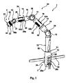
図1は保持アームの形式である保持装置1を示す。保持装置は、保持装置1をベース3に取り付ける近位端部2を有する。この実施例に基づくと、ベース3は手術台(手術台は図1に示されていない)の標準レールのように設計される。保持装置1は増設設備6(図2を参照)を受け止めるための遠位端部4も有する。
FIG. 1 shows a holding device 1 which is a type of holding arm. The holding device has a
図1および図2に示された保持装置は7つのアームセグメント10、12、14、16、18、20、22を有し、関節11、13、15、17、19、21、23が個別のアームセグメント10〜22の間に提供されている。第1アームセグメント10は、近位端部を形成し、保持装置1をベース3に固定することができるである手段によって締付けジョー(jaw)24を有する。保持装置全体を切り替えるための電源ボタン26と、2つの連結部28a、28bと、緊急停止ボタン30ともアームセグメント10に提供され、連結部28a、28bを介して、電力と例えば制御信号などの資料とが保持装置に供給され、連結部28a、28bを介して、資料は保持装置から例えば手術システムとの外部ユニットへ転送されてもよい。
The holding device shown in FIGS. 1 and 2 has seven
関節11、15、19、23は旋回関節のように設計され、関節13、17、21は蝶番関節(ヒンジ継手、hinge joint)のように設計される。図1を参照すると、すなわち、関節11、15、19、23の回転軸は実質的に図面の平面にあるが、関節13、17、21の回転軸は図面の平面に実質的に垂直である。
The
各関節11、13、15、17、19、21、23において、保持装置1は、保持装置および/または増設設備(図2を参照)を表示するための表示ユニット32、34、36、38、40、42、44を有する。
At each of the
この実施例に基づくと、表示ユニット32、34、36、38、40、42、44は環状の光源のように、特にLEDリングのように、実質的に設計されている。各リングの中心軸は対応する関節11、13、15、17、19、21、23の回転軸と実質的に同軸的である。よって、単一のLEDリングは各関節11、15、19、23に提供され、2つのLEDリングは各関節13、17、21に提供される。2つのLEDリングは前関節部17’と後関節部17”(単なる例示的に参照符号を用いて図2に標記される)において提供される。すなわち、各表示ユニットは常に観察可能である。
Based on this embodiment, the
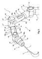
この実施例(図1および図2を参照)に基づくと、保持装置は操作設備50も有する。操作設備50を通して、保持アームは所望ポーズをとらせることができ、手術者と7つのアームセグメント10、12、14、16、18、20、22のうちに1つとの間の接触が起こるとき、操作設備50は関連する関節11、13、15、17、19、21、23を解放するように適用される。この目的のために、この実施例に係る操作設備50は3つの接触エリア52、54、56を有し、各接触エリア52、54、56は異なるアームセグメント16、20、22に配置されている。よって、1つの接触エリア52がアームセグメント16に配置されており、1つの接触エリア54がアームセグメント20に配置されており、1つの接触エリア56がアームセグメント22に配置されている。各接触エリア52、54、56は分離した接触部材52a、52b、52c、54a、54b、54c、56aを有する。個別の接触部材は接触感知表面のように設計されており、よって、1つ以上の関連する関節は手術者と対応する接触部材との間の接触が起こるときに解放される。
Based on this embodiment (see FIGS. 1 and 2), the holding device also has operating
この実施例に基づくと、3つの接触部材52a、52b、52c、54a、54b、54cは各アームセグメント16および22に提供される。アームセグメント22に環状の接触部材56が配置され、環状の接触部材56は、遠位端部において受け止められた増設設備のインターフェースにある機能を制御するために、その中心軸の周りを回転してもよい。
Based on this embodiment, the three
この実施例において、接触部材は以下の規則に基づいて個別の関節11、13、15、17、19、21、23と関係する。手術者とアームセグメント16との間の接触が起こるとき、すなわち、手術者と接触エリア52の接触部材52a、52b、52cとの間の接触が起こるとき、関節15、13、11が解放される。この時点で手術者は3自由度を制御することができる。これは、手動でよく管理されることができるという制御の程度であり、この制御において、保持装置は手動で所望ポーズにもたせることができる。手術者がアームセグメント16と接触してくるとき、関節15、13、11は解放され、好ましくは、対応する表示ユニット32、34、36はこのような解放を指示する。すなわち、図1および図2にしめされた実施例において、このような解放はLEDリングの点灯によって指示される。
In this embodiment, the contact members relate to
アームセグメント20が接触されるとき、すなわち、接触エリア54が接触されるとき、特に接触部材54a、54b、54cが接触されるとき、関節19、17は解放される。好ましくは、したがって、この解放は表示ユニット36、38によって表示される。最後に、アームセグメント22が接触されるとき、すなわち、接触エリア56が接触されるとき、特に接触部材56aが接触されるとき、関節21、23は解放され、この解放は好ましくは表示ユニット42、44である手段によって指示される。
The
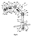
図2を参照すると、開創器の形式である増設設備6は遠位端部4に受け止められている。1つ以上の力センサは開創器6が受け止められた遠位端部4におけるインターフェースで配置され、この力センサである手段によって、長軸Lの方向に作用する張力を検出することができる。これらのセンサである手段によって、長軸Lの周りのインターフェースにおいて対応するトルクを検出するが可能であり、長軸Lに垂直する、対応するトルクを検出するも可能である。表示ユニット44は増設設備6の状態を指示するように構成されており、特には所定限界以下である特定の力が存在するかを指示するように構成されている。外科手術に渡って、大き過ぎる力が長い期間で開創器6に加えられ、副作用が操作エリアから離れて保持された組織に与えるリスクがある。この問題は、前述した力を測定してその力が所定限界以下であるかを判断することによって、緩和されまたは回避されることができる。
Referring to FIG. 2, the extension facility 6 in the form of a retractor is received at the distal end 4. One or more force sensors are arranged at an interface at the distal end 4 where the retractor 6 is received, and by means of this force sensor, the tension acting in the direction of the long axis L can be detected. By means of these sensors, it is possible to detect the corresponding torque at the interface around the long axis L, and it is also possible to detect the corresponding torque perpendicular to the long axis L. The
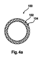
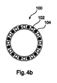
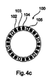
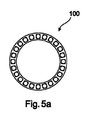
図3a〜図7cは本発明に係る表示ユニットの異なる実施例、および、保持装置および/または増設設備の状態を指示するという表示ユニットの用途を示し、当該状態は対応する関節の解放および/または固定と異なる。図3a〜図7cに示された全ての表示ユニットは単一のリングのように設計されている。図3aは本発明の好ましい実施例における表示ユニット100を示す。表示ユニット100はリングの形状であり、環状に配置された複数のLED102(単なる例示的に参照符号を用いて図3aに標記される)を有する。図3a、図3bに示された実施例に基づくと、LED102は、この実施例に係る表示ユニットが利用可能であるように、例えば、表示ユニット34、38または42のように、図面の平面に配向されている。よって、表示ユニット100は第1状態にあるように示されており、同じ表示ユニット100は第2状態にあるように示されている。理解されるべきなのは、2つの状態は図3aにおいてオフ状態であって図3bにおいてオン状態であってもよいことである。代替的に、図3aは第1色で発光している表示ユニット100を示すが、図3bは異なる第2色で発光している表示ユニット100を示すことも考えられる。このような視覚化は、特に保持装置の解放状態および/または固定状態を指示することに利用され、すなわち、対応する関節が固定されている解放されているかを指示することに利用される。本発明の異なる変形例はこの観点で考えられて好ましい。第1実施例において、図3a、図3bに示された表示ユニット100は保持装置1(図1、図2を参照)の内部制御器と連結している。手術者と接触部材52a、52b、52c、54a、54b、54c、56aの1つとの間のタッチ接触が検知されるときに表示設備100が第1色で発光する観点からみると、この構成が好ましい。この観点で、好ましくは、対応する関節は接触時に即時解放されるのではなく、例えば2秒の遅延を経てから解放される。したがって、表示ユニットによって表示されるものは、関節の解放または固定ではなく、操作設備が作動されるという事実であるため、手術者は関節が実際に開放される前に自身の動きを中止しまたは確認するのに十分な時間を有する。全ての関節が解放されるとき、1つの表示ユニット100しか点灯しないように配置することも可能である。他の好ましい実施例において、特定な関節に指定されない追加の表示ユニットはアームセグメント10(図1を参照)に提供される。この表示ユニットは保持装置における全ての関節が解放されることを指示する。このような場合、対応する関節と関係する個別の表示ユニット32、34、36、38、40、42、44は、これらの関節が解放されることを別々で指示しないことが考えられる。
3a-7c show different embodiments of the display unit according to the invention and the use of the display unit to indicate the state of the holding device and / or extension equipment, the state of which corresponds to joint release and / or. Different from fixed. All display units shown in FIGS. 3a-7c are designed as a single ring. FIG. 3a shows the
実施例(図3a、図3b)の他の好ましい変形例において、表示ユニット100は関節におけるブレーキの信号線と結合されている。このような実施例において、ブレーキを起動するために、電圧がブレーキに提供されているかに関わらず表示ユニット100は点灯する。なお、代替的にまたは追加的に、表示ユニット100はブレーキのためのバスシステムと結合されており、よって、表示ユニットはブレーキのための制御信号を拾い上げて当該制御信号にしたがって点灯し、よって、ブレーキはその解放のための制御信号を受け止めたことが指示される。
In another preferred modification of the embodiment (FIGS. 3a, 3b), the
図3a、図3bに示された実施例も、対応する関節の解放または固定と異なる、保持装置または増設設備の状態を指示するように好ましく利用され、この実施例において、表示ユニット100は2つ以上の異なる色の間で切り替える(特に、その全体で切り替える、すなわち、全てのLED102は同じ色である)。好ましくは、保持装置が利用される具体的な応用に基づいて、表示ユニット100はこのような利用のために利用される色で発光する。例えば、保持装置がENT手術に利用されている場合、全ての表示ユニットは(好ましくはブレーキが固定されているときに)緑色で発光する。同じ保持装置が開腹手術に利用される場合、全ての表示ユニットは(好ましくはブレーキが固定されているときに)青色で発光する。よって、保持装置が現在の応用のために正しく設置されているか、および/または、手術システムから正しく資料を供給されているか、について手術では即時認識されることができる。例えば、異なる応用が関節においてブレーキによる異なる行為を必要とするとき、または、異なる量の力が保持装置に加えられるとき、または、特定な量およびグループの増設装置が許可されるとき、この技術は有利である。この観点で、対応する資料は、インターフェースを介して提供されまたはポーリングされ、好ましくは保持装置1の遠位端部および近位端部において提供されまたはポーリングされ、内部制御器において処理され、そして内部制御器は対応する信号を表示ユニット100へ送る。
The embodiments shown in FIGS. 3a and 3b are also preferably utilized to indicate the state of the holding device or extension facility, which is different from the release or fixation of the corresponding joint, in which two
他の変形例において、図3a、図3bに示された表示ユニット100は関節で1つ以上の位置センサと結合しており、好ましくは、対応する表示ユニットは対応する関節で1つの位置センサと結合している。このような実施例において、固定および/または解放と異なる状態は関節の移動の状態である。すなわち、手術者はまず操作設備50である手段によって1つ以上の関節を解放し、この解放は後で表示ユニット(N)によって指示されない。対応する表示ユニットは手術者が関節を移動させるまで点灯しない。手術者はアームセグメント20(図1を参照)を掴み、掴む過程で接触エリア54と接触してくることが考えられる。よって、関節19および関節17、15は解放される。手術者が続いて関節17のみを旋回する場合、表示ユニット38のみが点灯する。このように、手術者はどの関節がここで移動されるかについてフィードバックを受け、追って自分の行っていることを確認することができる。
In another variant, the
第2実施例において、図4a〜図4cおよび図5a〜図5cは図3a、図3bから基本的に知られる種類の表示ユニット100を示す。図4a〜図5cは表示ユニットを示し、示された表示ユニットは2つ以上の異なる色の間に切り替えられるだけではなく、個別のLED102、103、104、106も異なる色であってもよく(図4a〜図4cを参照)、または光度(luminous intensity)を変化してもよい(図5a〜図5cを参照)。保持装置が位置付けられ、手術者にこのような位置付けについてフィードバックが与えられるべきときに特に有利である。1つの変化例において、好ましくは、図5a〜図5cに示された種類の表示ユニット100は関節が移動されるときに点灯し、例えば、表示ユニット38は関節17が移動されるときに点灯する。光度は移動の速度に基づいて変化してもよい。1つのこのような場合において、図5aは移動していないことを指示する表示ユニット100を示し、図5bは中速度で行う移動を示し、図5cは高速度で行う移動を示す。
In the second embodiment, FIGS. 4a-4c and 5a-5c show a
好ましくは、保持装置の関節における位置センサも測定のために、特に移動を測定するために、利用される。保持装置1を操作して保持装置1を移動させることによって、例えば、二点の間の距離を測定すること、例えば、患者の組織の2つの部分の間の距離を測定することが可能である。このように設計された保持装置が対応する測定モードに置かれるとき、好ましくは、表示装置が測定モードに置かれることを指示する。測定モードに置かれることは図4a〜図4cの例示のように示される。図4a〜図4cは、手術者が保持装置を現在のポーズから所望ポーズに移動させる機能も示し、このような場合において、指示される状態は所望ポーズとの距離(distance)である。したがって、図4aにおいて、全てのLED102、104は1つの色で発光し、よって、現在のポーズは所望ポーズと同一でないことが指示される。図4bにおいて、手術者が保持アームを所望ポーズへ移動させたことを指示する表示ユニット100を示し、各第2LED102、104は異なる色であり、すなわち、半分のLEDが第1色で発光して他の半分のLEDが第2色で発光する。図4cは、手術者が保持装置を所望ポーズへさらに移動させたことを示し、第4LED106のみは第1色であるが、LED102、103、104は第2色を適用した。所望ポーズに達したとき、全てのLED102、103、104、106は第2色に切り替えられ、手術者は所望ポーズに達したことを認識する。好ましくは、所望ポーズに達したときに関節における全てのブレーキが自動的にかかり、よって、全ての関節が固定される。図6a〜図6cは、表示ユニットが測定機能または測定モードを指示する他の形式を示す。LEDリングの形式である表示ユニット100は4つの異なるセクション110、112、114、116を有し、これらのセクションは交互に2つの異なる色を有する。個別のLED102(複数の個別のLEDのうちに1つだけが参照符号を用いて図6a〜図6cに標記される)は、4つのセクション110、112、114、116によって形成されるパターンが図6a〜図6cにおける右側へ回転するように、内部制御器によって制御され、よって、個別のセクション110、112、114、116は対応するアームセグメントの移動につれて「照らし回る(roam)」。例えば、関節17が解放され、保持装置において関節17と遠位端部4との間の部分が旋回される場合、移動の状態を指示するために、および、どのくらいの速度およびどのような角度で保持装置の特定な部分を旋回しているかを手術者に認識を促すために、個別なセクション110、112、114、116は旋回移動の方向に対応する速度で移動する。
Preferably, a position sensor at the joint of the holding device is also utilized for measurement, especially for measuring movement. By manipulating the holding device 1 to move the holding device 1, it is possible, for example, to measure the distance between two points, for example, the distance between two parts of the patient's tissue. .. When the holding device thus designed is placed in the corresponding measurement mode, it preferably indicates that the display device is placed in the measurement mode. Being placed in the measurement mode is shown as illustrated in FIGS. 4a-4c. 4a-4c also show the ability of the surgeon to move the holding device from the current pose to the desired pose, in which case the indicated state is the distance from the desired pose. Therefore, in FIG. 4a, all
同様な図示は図7a〜図7cに示され、図7a〜図7cにおいて、LEDリングのように設計された表示ユニット100は2つのセクション118、120を有する。これらのセクションのそれぞれは、第1色で発光するLED122、124から第2色で発光する126、128への色勾配を有する。矢印130、140はパターンが回転する方向を示す。
Similar illustrations are shown in FIGS. 7a-7c, where in FIGS. 7a-7c, the
表示ユニット100(特に図3a、図3bに示されるように)である手段による視覚化の他の実施例は、アームが旋回していない限り、または、所定の保存された許容範囲以内で旋回する限り、表示ユニット100が第1色で発光する実施例である。アームが旋回しなくなるようなときまで第1色は表示される。これは超微細マニピュレータ(ultrafine manipulator)が増設設備として保持装置に受け止められるときに好ましい。このように、手術者は、保持装置が受けられ可能な許容範囲以内になるまで待つように通知される。保持装置が旋回しているとき、どのような増設設備でもさらに移動すべきではない。関節における位置センサである手段によって、保持装置が揺れるとき、または、関節がその固定状体において旋回されてブレーキの力に対抗するときは検出可能である。これは位置センサおよび/または方位センサである手段によって検出されることができ、そして表示ユニットである手段によって指示されることができる。よって、手術者は、例えば、保持装置が所望ポーズに維持しているかについて、または、特定な関節がブレーキの力に対抗して移動したかについてフィードバックを受ける。
Another embodiment of visualization by means of the display unit 100 (particularly as shown in FIGS. 3a and 3b) is that the arm is not swiveled or swivels within a predetermined stored tolerance. As long as it is an embodiment, the
好ましくは、図6a〜図7cに示される種類の表示ユニットは教示を、すなわち、一連のポーズ(軌跡)を、保持装置へ転送する。手術などの前に、保持装置を用いて異なるポーズを経験し、これらのポーズを保存しおよび/または試験することに有利である可能性がある。この観点で、保持装置を教示モードにさせ、教示モードにおいては、経験されるポーズは内部制御器によって検出されて保存されることが可能であって好ましい。表示ユニットは相応にこの状態を指示し、特に図7a〜図7cに示される種類のパターンを用いて指示する。 Preferably, the display unit of the type shown in FIGS. 6a-7c transfers the teaching, i.e., a series of poses (trajectories) to the holding device. It may be advantageous to experience different poses with a holding device and store and / or test these poses prior to surgery and the like. From this point of view, it is preferable that the holding device is put into the teaching mode, and in the teaching mode, the pose experienced can be detected and stored by the internal controller. The display unit indicates this state accordingly, in particular using the types of patterns shown in FIGS. 7a-7c.
図8a〜図9bは他の実施例に係る、二重リングのLEDの形式である表示ユニット200を示す。表示ユニット200(図8aを参照)は第1LEDリング202と第2LEDリング204とを有する。複数のLED206、208(1つのLED206と1つのLED208のみが参照符号を用いて標記される)は各LEDリング202、204に配置されている。このような実施例において、2つのLEDリング202、204を互いに独立に制御することは可能である。理解されるべきなのは、全てのLEDリング202、204が唯一の列のLEDから構成される必要がなく、各LEDリングは2列以上のLEDを有してもよく、好ましくは、2列以上のLEDが一致に制御されることである。実施例は3つ以上のLEDリングを有することが好ましいのも理解されるべきである。
8a-9b show a
例えば、図8a、図8bは、回転パターンが例えば図6a〜図7cを参照して説明されたLEDリング202、204において表示されることを示す。図8a、図8bにおいて、矢印210、212は外側のLEDリング202の回転方向を示すが、矢印214、216は内側のLEDリング204の回転方向を示す。図8aはパターンが正反対の方向に移動する(矢印210、212と矢印214、216とは正反対の方向を指す)ことを示し、図8bは同じ方向に回転することを示す。好ましくは、このような表示(図8a)は、例えば、2つの関節が解放されるときに正反対の方向に移動し、または、標的ポーズを達するためのように移動する。同じ方向の回転(図8b)を用いる表示は、同じ方向の移動が要求されることを指示することに利用されてもよい。
For example, FIGS. 8a and 8b show that the rotation pattern is displayed on the LED rings 202, 204 described, for example, with reference to FIGS. 6a-7c. In FIGS. 8a and 8b,
図9a、図9bは、内側から外側へ矢印218によって指示されるように放射状に移動するパターンを示す。このようなエフェクトは3つ以上のLEDが提供されるときに強化される。外側から内側へ動くパターン、すなわち、矢印218と反対の方向に動くパターンを用いる視覚化は、考えられて好ましい。好ましくは、このような視覚化は、特に1つ以上の関節によるまたは中央制御ユニットによるソフトウェアモジュールの更新を指示するのに利用される。
9a and 9b show patterns that move radially from the inside to the outside as indicated by the
図10は保持装置1の他の実施例を示す。当該保持装置1は、図1および図2に示される保持装置1とはいくつの特徴が同一であり、よって、同一で同様な部材は図1および図2における同じ参照符号を用いて標記される。この観点で、前述した図1および図2の説明全体は参照される。以下、主な注目点は、それぞれ、図1および図2における実施例との差異、および、図10、11、12における実施例との差異に置かれる。 FIG. 10 shows another embodiment of the holding device 1. The holding device 1 has some features that are the same as those of the holding device 1 shown in FIGS. 1 and 2, and thus the same and similar members are marked with the same reference numerals in FIGS. 1 and 2. .. From this point of view, the entire description of FIGS. 1 and 2 described above is referred to. Hereinafter, the main points of interest will be placed on the differences from the examples in FIGS. 1 and 2, and the differences from the examples in FIGS. 10, 11 and 12, respectively.
保持アーム1は図1および図2に示された保持アームと実質的に同じ構造を有するが、それぞれ2つの表示器260、261、262、263、264、265を有する表示ユニット250、252、254が3つの多関節型(articulated)の関節13、17、21に配置されるところが異なる。表示器260、262、264のみが図10において見え、表示器261、263、265は図10において保持装置1の後側に表示器260、262、264と平行に配置される。
The holding arm 1 has substantially the same structure as the holding arms shown in FIGS. 1 and 2, but has
表示器260、261、262、263、264、265は丸い形をし、その中心軸が対応する関節213、217、221の旋回軸と同軸的であるように配置されている。
The
図10は、対応する関節13、17が既にその位置にある時間期間を表示する表示器260、262を示す。特定な一連の動きが計画されるとき、これは特に有用である。図10において、表示器264はアームセグメント22が傾いた環状範囲を示す。この手段によって、手術者は増設設備が受け止められた最後のアームセグメントの方位についてフィードバックを受ける。
FIG. 10
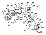
他の実施例と対称的に、図11および図12は、表示器260、262、264が解放および/または固定と異なる状態を指示するのに利用される実施例を示す。
In contrast to other embodiments, FIGS. 11 and 12 show examples in which
図11に基づくと、表示器260、262、264は、対応する関節13、17、21が保持装置1の操作エリアから離れる前にどの方向にどのくらいの角度で旋回可能であるかを指示する。表示器264は関節21の回転の方向を指示するだけではなく、関節19の回転の方向も指示し、関節19の回転の方向は表示器264にある水平矢印によって指示される。このような視覚化は表示262、260でも可能であるが、この実施例に示されていない。
Based on FIG. 11,
図12は保持装置1の状態の視覚化の他例を示す。個別の関節13、17、21に作用している重量は表示器260、262、264に記入され、よって、手術者は、保持装置1によって耐えている負担がまだ許容範囲にあるか、および、増設設備に作用している負担が過度にあるかを評価することができる。
FIG. 12 shows another example of visualization of the state of the holding device 1. The weight acting on the
表示器260、261、262、263、264、265が表示ユニットとして利用されるとき、状態などについての他の指示は考えられる。好ましくは、個別の表示器は接触感知の表示器の形式で提供され、保持装置1のプロファイルを入力するためにも利用される。好ましくは、例えば、オン/オフスイッチが表示器260、261に表示され、保持装置は表示器260、261に接触することによってオンとオフと切り替え可能である。保持装置1の現在のポーズは表示器260、261、262、263、264、265に接触することによって保存されることが同様に考えられる。他の表示されるものは、資料転送、患者資料、X線画像などの患者画像、CT/MR画像、計画ステップ、増設設備のロボット制御のアクセス、および、増設設備のための入力指令、例えば他のシステムとの連結などの運転環境の表示、を含む。
When the
図13および図14は保持装置1とユーザとを備えるシステムの基本構造を示す。保持装置1は操作部材300を備え、操作部材300は触覚センサ302と音響センサ304と光センサ306とを含んでもよい。触覚センサの1つの例は前述した操作設備50である。内部的に、保持装置1は処理ユニット308を有し、処理ユニット308はソフトウェアモジュール310を有する。ブレーキ312は、関節に配置され、アイドル状態で閉じされ、電圧の適用によって開放される。よって、保持装置は「受動的」な保持装置のように設計され、電源が断たれる状態において保持装置において全ての関節は固定される。この実施例に基づくと、表示ユニットは発光ユニット314の形式で提供され、各発光ユニット314は1つの関節および1つのブレーキに指定される。例えば、発光ユニット1はブレーキ1に指定され、発光ユニット2はブレーキ2に指定される、等々。好ましくは、個別の発光ユニットは図1〜図7cに示される形式で提供される。処理ユニットは操作部材と連結していて操作部材を分析し、特には検出される触覚信号、音響信号または光信号を分析する。これらの信号はソフトウェアモジュール310を利用して分析され、対応するブレーキ312は解放されるおよび/または固定される。解放および/または固定は後で対応する発光ユニット314によって指示されない。この実施例に基づくと、保持装置1は、単なる個別の関節の解放および固定を指示する能力があるが、他のいかなる状態も指示する能力がない。
13 and 14 show the basic structure of a system including a holding device 1 and a user. The holding device 1 includes an operating
図14は、表示ユニットがどのように解放および固定と異なる状態を表示するように設計されるかを示す。図13に示される保持装置と構造上基本的に同様である保持装置1は追加のセンサ320を有する。センサ320は、例えば、1つ以上の位置センサ322を含み、好ましくは各関節において1つ以上の位置センサ322を含む。センサ320は、例えば、1つ以上の加速度センサ324を含み、好ましくは各関節において1つ以上の加速度センサ324を含む。センサ320は、例えば、1つ以上の力センサ326を含み、好ましくは遠位端部4において1つ以上の位置センサ326を含み、少なくとも保持装置1において1つ以上の位置センサ326を含む。センサ320は、例えば、1つ以上のトルクセンサ328を含み、好ましくは各関節ならびに保持装置1の遠位端部4および近位端部2において1つ以上のトルクセンサ328を含む。センサ320は、例えば、少なくとも1つの衝撃センサ(bump sensor)330と少なくとも1つの温度センサ322とを含む。センサ320によって収集される資料に基づいて、ソフトウェア310は、状態を判断して表示ユニット100に当該状態を指示させるように、特に発光ユニット314である手段によって指示させるように、構成されている。
FIG. 14 shows how the display unit is designed to display different states than open and fixed. The holding device 1, which is structurally basically similar to the holding device shown in FIG. 13, has an additional sensor 320. The sensor 320 includes, for example, one or more position sensors 322, preferably one or more position sensors 322 at each joint. The sensor 320 includes, for example, one or more acceleration sensors 324, preferably one or more acceleration sensors 324 at each joint. The sensor 320 includes, for example, one or more force sensors 326, preferably one or more position sensors 326 at the distal end 4, and at least one or more position sensors 326 at the holding device 1. The sensor 320 includes, for example, one or more torque sensors 328, preferably one or more torque sensors 328 at each joint and at the distal end 4 and
図15は表示ユニット400の他の実施例を示す。表示ユニット400は基本的に前述した実施例と関連して、特にその幾何配置および機能に関して、設計される。第1実施例と異なり、この実施例(図15)において説明される表示ユニット400は、可視波長範囲である光を放出するLED402(複数のLED402のうちに1つだけが参照符号を用いて図15に標記され、全てのLED402が五角形によって囲まれている)を有するだけではなく、赤外波長範囲である光を放出する赤外線LED404(複数の赤外線LED404のうちに1つだけが参照符号を用いて図15に標記され、全ての赤外線LED404が菱形によって囲まれている)も有する。これは、保持装置の状態を人間に対して視覚的に知覚可能な形式で指示することを可能とするだけではなく、保持装置の状態を赤外線放射である手段によって指示することも可能とするため、保持アームの状態は赤外線センサと協働する手術ナビゲーションシステムによって検出されることができる。
FIG. 15 shows another embodiment of the
図15は、2つのゾーン406、408が提供されてもよいこと、すなわち、リングのように設計された表示ユニット400が全体として2つの部分に分けられてもよいこと、を示す。これは表示されるべき2つの異なる状態を単一の表示ユニット400である手段によって表示することを可能とし、すなわち、第1状態のために第1ゾーン406を提供して第2状態のために第2ゾーン408を提供することによって表示することを可能とする。例えば、保持装置の移動はゾーン406によって指示されるが、関節におけるいかなるブレーキの開放もゾーン408によって指示される。前述した全ての組合せはここで可能であって、これによって明示に説明される。
FIG. 15 shows that two
Claims (10)
前記保持装置(1)をベースに取り付ける近位端部(2)および増設設備(6)を受け止める遠位端部(4)と、
少なくとも1つの第1アームセグメントおよび第2アームセグメント(12、14)であって、前記第1アームセグメント(12)が第1関節(13)と連結し、前記第2アームセグメント(14)が第2関節(15)と連結し、各前記関節(13、15)は固定可能で解放可能である、前記少なくとも1つの第1アームセグメントおよび第2アームセグメント(12、14)と、
前記保持装置(1)に所望ポーズをとらせるように、対応する前記関節(13、15)を解放するおよび/または固定する操作設備(50)と、
前記第1関節(13)に配置された第1表示ユニット(34、100)および前記第2関節(15)に配置された第2表示ユニット(36、100)と、を備え、
前記第1表示ユニット(34、100)および前記第2表示ユニット(36、100)は対応する関節が解放または固定であるかを指示するように構成されており、
前記操作設備(50)は、手術者と第1アームセグメントおよび第2アームセグメントの1つとの間の接触が起こるときに前記対応する関節(13、15)を開放するように構成されており、
少なくとも1つの表示ユニット(34、36、100)は、前記対応する関節(13、15)の旋回軸の周りにあるリングのように実質的に設計されている、保持装置(1)。 In holding devices (1), which are holding arms and / or tripods, especially for medical applications, especially to support accessories, and especially to support surgical mechatronic assistive systems and / or surgical instruments. There,
Proximal end (2) for attaching the holding device (1) to the base, distal end (4) for receiving extension equipment (6), and
At least one first arm segment and a second arm segment (12, 14), the first arm segment (12) is connected to the first joint (13), and the second arm segment (14) is the first. The at least one first arm segment and the second arm segment (12, 14), which are connected to the two joints (15) and each of the joints (13, 15) are fixed and releasable,
An operating facility (50) that releases and / or fixes the corresponding joints (13, 15) so that the holding device (1) poses as desired.
A first display unit (34, 100) arranged at the first joint (13) and a second display unit (36, 100) arranged at the second joint (15) are provided.
The first display unit (34, 100) and the second display unit (36, 100) are configured to indicate whether the corresponding joint is open or fixed.
The operating equipment (50) is configured to open the corresponding joints (13, 15) when contact occurs between the surgeon and one of the first arm segment and the second arm segment.
At least one display unit (34, 36, 100) is a holding device (1) that is substantially designed like a ring around the swivel axis of the corresponding joint (13, 15).
Applications Claiming Priority (3)
| Application Number | Priority Date | Filing Date | Title |
|---|---|---|---|
| EP15180826.8 | 2015-08-12 | ||
| EP15180826.8A EP3130305B1 (en) | 2015-08-12 | 2015-08-12 | Medical holding arm |
| PCT/EP2016/069167 WO2017025607A1 (en) | 2015-08-12 | 2016-08-11 | Medical holding arm having annular led display means |
Publications (3)
| Publication Number | Publication Date |
|---|---|
| JP2018529488A JP2018529488A (en) | 2018-10-11 |
| JP2018529488A5 JP2018529488A5 (en) | 2019-05-09 |
| JP6767486B2 true JP6767486B2 (en) | 2020-10-14 |
Family
ID=53886911
Family Applications (1)
| Application Number | Title | Priority Date | Filing Date |
|---|---|---|---|
| JP2018527011A Active JP6767486B2 (en) | 2015-08-12 | 2016-08-11 | Medical holding arm with annular LED display means |
Country Status (6)
| Country | Link |
|---|---|
| US (2) | US10342636B2 (en) |
| EP (3) | EP3130305B1 (en) |
| JP (1) | JP6767486B2 (en) |
| KR (1) | KR102372151B1 (en) |
| CA (1) | CA2995144C (en) |
| WO (1) | WO2017025607A1 (en) |
Families Citing this family (118)
| Publication number | Priority date | Publication date | Assignee | Title |
|---|---|---|---|---|
| EP1814474B1 (en) | 2004-11-24 | 2011-09-14 | Samy Abdou | Devices for inter-vertebral orthopedic device placement |
| US8764806B2 (en) | 2009-12-07 | 2014-07-01 | Samy Abdou | Devices and methods for minimally invasive spinal stabilization and instrumentation |
| US8845728B1 (en) | 2011-09-23 | 2014-09-30 | Samy Abdou | Spinal fixation devices and methods of use |
| US20130226240A1 (en) | 2012-02-22 | 2013-08-29 | Samy Abdou | Spinous process fixation devices and methods of use |
| US9198767B2 (en) | 2012-08-28 | 2015-12-01 | Samy Abdou | Devices and methods for spinal stabilization and instrumentation |
| US9320617B2 (en) | 2012-10-22 | 2016-04-26 | Cogent Spine, LLC | Devices and methods for spinal stabilization and instrumentation |
| US10368878B2 (en) | 2013-06-11 | 2019-08-06 | Orthotaxy | System for positioning a surgical device |
| KR20230162122A (en) | 2015-02-20 | 2023-11-28 | 스트리커 코포레이션 | Sterile barrier assembly, mounting system, and method for coupling surgical components |
| AU2016243292B2 (en) | 2015-03-27 | 2020-12-24 | Sonitrack Systems, Inc. | Rapidly repositionable powered support arm |
| US10857003B1 (en) | 2015-10-14 | 2020-12-08 | Samy Abdou | Devices and methods for vertebral stabilization |
| DE102016202881B4 (en) * | 2016-02-24 | 2018-01-18 | Kuka Roboter Gmbh | Operating device for manipulator |
| DE102016118123A1 (en) | 2016-09-26 | 2018-03-29 | Medineering Gmbh | Medical support arm for integration into an operating navigation system |
| US10744000B1 (en) | 2016-10-25 | 2020-08-18 | Samy Abdou | Devices and methods for vertebral bone realignment |
| US10973648B1 (en) | 2016-10-25 | 2021-04-13 | Samy Abdou | Devices and methods for vertebral bone realignment |
| DE102017111296B3 (en) | 2017-05-23 | 2018-08-02 | Medineering Gmbh | Robotic manipulator for guiding an endoscope with parallel kinematics |
| DE102017111302A1 (en) | 2017-05-23 | 2018-11-29 | Medineering Gmbh | Medical mechatronic male and female interface device |
| DE102017111289B3 (en) | 2017-05-23 | 2018-08-23 | Medineering Gmbh | Passive surgical manipulator with hand-held drive unit |
| US11751966B2 (en) | 2017-07-27 | 2023-09-12 | Intuitive Surgical Operations, Inc. | Medical device handle |
| JP6633580B2 (en) * | 2017-08-02 | 2020-01-22 | ファナック株式会社 | Robot system and robot controller |
| JP7130933B2 (en) * | 2017-09-29 | 2022-09-06 | セイコーエプソン株式会社 | robot |
| WO2019102562A1 (en) * | 2017-11-22 | 2019-05-31 | 三菱電機株式会社 | Display actuator and cobot |
| JP7186498B2 (en) * | 2017-11-27 | 2022-12-09 | アズビル株式会社 | I/O device |
| US10987175B2 (en) | 2017-12-06 | 2021-04-27 | Medtech S.A. | Robotic shoulder repair and reconstruction |
| AU2019205201B2 (en) * | 2018-01-04 | 2020-11-05 | Covidien Lp | Systems and assemblies for mounting a surgical accessory to robotic surgical systems, and providing access therethrough |
| USD901694S1 (en) | 2018-01-17 | 2020-11-10 | Auris Health, Inc. | Instrument handle |
| USD873878S1 (en) | 2018-01-17 | 2020-01-28 | Auris Health, Inc. | Robotic arm |
| CN108013936B (en) * | 2018-02-08 | 2023-07-11 | 哈尔滨工业大学深圳研究生院 | Pneumatic operation arm based on ball joint |
| US10687792B2 (en) | 2018-03-12 | 2020-06-23 | Zimmer Biomet CMF and Thoracic, LLC | End effector coupler for surgical arm |
| US10835345B2 (en) * | 2018-03-12 | 2020-11-17 | Zimmer Biomet CMF and Thoracic, LLC | End effector coupler for surgical arm |
| US10772704B2 (en) | 2018-03-12 | 2020-09-15 | Zimmer Biomet CMF and Thoracic, LLC | End effector coupler for surgical arm |
| USD878585S1 (en) | 2018-03-12 | 2020-03-17 | Zimmer Biomet CMF and Thoracic, LLC | End effector coupler stem |
| EP4324583A2 (en) * | 2018-04-27 | 2024-02-21 | Milwaukee Electric Tool Corporation | Compact multi-material cut-off tool |
| JP7379941B2 (en) * | 2018-09-07 | 2023-11-15 | マックス株式会社 | tying machine |
| US11179248B2 (en) | 2018-10-02 | 2021-11-23 | Samy Abdou | Devices and methods for spinal implantation |
| US11167433B2 (en) * | 2018-10-02 | 2021-11-09 | Flexiv Ltd. | Sealing apparatus and articulated robot |
| WO2020086403A1 (en) | 2018-10-22 | 2020-04-30 | Smith & Nephew, Inc. | Device identification using surgical navigation system |
| AU2019391083A1 (en) | 2018-12-04 | 2021-06-10 | Mako Surgical Corp. | Mounting system with sterile barrier assembly for use in coupling surgical components |
| EP3663054A1 (en) * | 2018-12-05 | 2020-06-10 | Siemens Aktiengesellschaft | Articulated arm robot |
| CN109464170B (en) * | 2018-12-18 | 2020-09-15 | 山东省千佛山医院 | Left auricle drag hook and mitral valve operation are with auxiliary assembly |
| WO2020132441A1 (en) | 2018-12-21 | 2020-06-25 | Smith & Nephew, Inc. | Actuated retractor with tension feedback |
| EP3899978A1 (en) | 2018-12-21 | 2021-10-27 | Smith&Nephew, Inc. | Methods and systems for providing an episode of care |
| WO2020139808A2 (en) | 2018-12-23 | 2020-07-02 | Smith & Nephew, Inc. | Ocd treatment method |
| US20220110683A1 (en) | 2018-12-23 | 2022-04-14 | Smith & Nephew, Inc. | Osteochondral defect treatment method and system |
| US20220117669A1 (en) | 2019-02-05 | 2022-04-21 | Smith & Nephew, Inc. | Augmented reality in arthroplasty surgery |
| WO2020180917A1 (en) | 2019-03-04 | 2020-09-10 | Smith & Nephew, Inc. | Co-registration for augmented reality and surgical navigation |
| US20220125535A1 (en) | 2019-03-11 | 2022-04-28 | Smith & Nephew, Inc. | Systems and methods associated with passive robotic arm |
| US20220160440A1 (en) | 2019-03-11 | 2022-05-26 | Smith & Nephew, Inc. | Surgical assistive robot arm |
| WO2020185819A2 (en) | 2019-03-11 | 2020-09-17 | Smith & Nephew, Inc. | Small form modular tracking device for computer assisted surgery |
| WO2020206216A1 (en) | 2019-04-05 | 2020-10-08 | Smith & Nephew, Inc. | Methods and system for manufacturing a joint implant |
| EP3962396A1 (en) | 2019-04-29 | 2022-03-09 | Smith&Nephew, Inc. | Multi-level positional tracking |
| US11389304B1 (en) | 2019-05-06 | 2022-07-19 | Smith & Nephew, Inc. | Devices, systems and methods for providing instrument orientation feedback |
| CN111655434A (en) * | 2019-06-12 | 2020-09-11 | 上海非夕机器人科技有限公司 | Robot and industrial robot with light device for indicating actuator status |
| WO2020257444A1 (en) | 2019-06-18 | 2020-12-24 | Smith & Nephew, Inc. | Computer controlled surgical rotary tool |
| DE102019117217B3 (en) * | 2019-06-26 | 2020-08-20 | Franka Emika Gmbh | Method for specifying an input value on a robot manipulator |
| US20230404684A1 (en) * | 2019-07-01 | 2023-12-21 | Smith & Nephew, Inc. | Surgical assistant device |
| KR102224793B1 (en) | 2019-07-11 | 2021-03-09 | 주식회사 케디엠 | A Inspection and improvement of arm and shoulder cumulative fatigue and concentration deterioration due to repeated use of surgical equipment for patient treatment |
| US20220265355A1 (en) | 2019-07-16 | 2022-08-25 | Smith & Nephew, Inc. | Systems and methods for augmented reality assisted trauma fixation |
| WO2021016092A1 (en) | 2019-07-19 | 2021-01-28 | Smith & Nephew, Inc. | Methods and systems for implanting a joint implant |
| WO2021026077A1 (en) * | 2019-08-05 | 2021-02-11 | Zimmer Biomet Spine, Inc. | Smart retractor blade |
| CN114466625A (en) | 2019-10-03 | 2022-05-10 | 史密夫和内修有限公司 | Registration of intramedullary canal during total knee replacement revision |
| WO2021072041A1 (en) | 2019-10-08 | 2021-04-15 | Smith & Nephew, Inc. | Methods for improved ultrasound imaging to emphasize structures of interest and devices thereof |
| WO2021076560A1 (en) | 2019-10-14 | 2021-04-22 | Smith & Nephew, Inc. | Surgical tracking using a 3d passive pin marker |
| WO2021087027A1 (en) * | 2019-10-30 | 2021-05-06 | Smith & Nephew, Inc. | Synchronized robotic arms for retracting openings in a repositionable manner |
| US11517334B1 (en) | 2019-11-04 | 2022-12-06 | Smith & Nephew, Inc. | Patient-specific guides for latarjet procedure |
| EP4061270A1 (en) | 2019-11-19 | 2022-09-28 | Smith & Nephew, Inc. | Elastography for ligament characterization |
| WO2021118995A1 (en) | 2019-12-13 | 2021-06-17 | Smith & Nephew, Inc. | Anatomical feature extraction and presentation using augmented reality |
| WO2021127161A1 (en) | 2019-12-18 | 2021-06-24 | Smith & Nephew, Inc. | Methods for attaching tracking arrays during navigated surgery and devices thereof |
| CA3162370A1 (en) | 2019-12-20 | 2021-06-24 | Ryan Lloyd Landon | Three-dimensional selective bone matching from two-dimensional image data |
| WO2021141830A1 (en) | 2020-01-06 | 2021-07-15 | Smith & Nephew, Inc. | Tensioner tool and sock with pressure sensor grid for use therewith |
| WO2021146540A1 (en) | 2020-01-15 | 2021-07-22 | Smith & Nephew, Inc. | Trial-first measuring device for use during revision total knee arthroplasty |
| CN114929124A (en) | 2020-01-22 | 2022-08-19 | 史密夫和内修有限公司 | Method and system for multi-stage robotically-assisted bone preparation for non-osseous cement implants |
| CN114901195A (en) | 2020-02-04 | 2022-08-12 | 史密夫和内修有限公司 | Improved and CASS-assisted osteotomy |
| CN114929149A (en) | 2020-02-07 | 2022-08-19 | 史密夫和内修有限公司 | Optical tracking system for augmented reality preparation |
| JP2023514042A (en) | 2020-02-11 | 2023-04-05 | スミス アンド ネフュー インコーポレイテッド | joint extension system |
| WO2021163474A1 (en) | 2020-02-13 | 2021-08-19 | Smith & Nephew, Inc. | Systems for robotic-assisted insertion of medical fasteners |
| EP4066774A4 (en) * | 2020-02-18 | 2022-11-30 | Riverfield Inc. | Medical robot |
| EP4107748A1 (en) | 2020-02-20 | 2022-12-28 | Smith&Nephew, Inc. | Methods for arthroscopic video analysis and devices therefor |
| WO2021174038A1 (en) | 2020-02-27 | 2021-09-02 | Smith & Nephew, Inc. | Fiducial tracking knee brace device and methods thereof |
| WO2021203082A1 (en) | 2020-04-03 | 2021-10-07 | Smith & Nephew, Inc. | User interface for digital markers in arthroscopy |
| WO2021203077A1 (en) | 2020-04-03 | 2021-10-07 | Smith & Nephew, Inc. | Methods for arthroscopic surgery video segmentation and devices therefor |
| CN115298694A (en) | 2020-04-10 | 2022-11-04 | 史密夫和内修有限公司 | Complementary optical tracking system and method thereof |
| WO2021216516A1 (en) | 2020-04-20 | 2021-10-28 | Smith & Nephew, Inc. | Fiducial marker devices |
| WO2021217030A1 (en) | 2020-04-24 | 2021-10-28 | Smith & Nephew, Inc. | Optical tracking device with built-in structured light module |
| EP4142611A1 (en) | 2020-04-27 | 2023-03-08 | Smith & Nephew, Inc. | Knee tensioner with digital force and displacement sensing |
| US20230165645A1 (en) | 2020-04-30 | 2023-06-01 | Smith & Nephew, Inc. | Kinematic coupling |
| WO2021231349A1 (en) | 2020-05-11 | 2021-11-18 | Smith & Nephew, Inc. | Dual scale calibration monomarker for digital templating in 2d imaging |
| WO2021247990A1 (en) | 2020-06-05 | 2021-12-09 | Smith & Nephew, Inc. | Automatic adjustment of tensioner device |
| WO2021257621A1 (en) * | 2020-06-16 | 2021-12-23 | Intuitive Surgical Operations, Inc. | Techniques for selective joint floating in a computer-assisted system |
| WO2021257672A1 (en) | 2020-06-18 | 2021-12-23 | Smith & Nephew, Inc. | Methods for autoregistration of arthroscopic video images to preoperative models and devices thereof |
| US20230301732A1 (en) | 2020-06-19 | 2023-09-28 | Smith & Nephew, Inc. | Robotic arm positioning and movement control |
| CN115802973A (en) | 2020-07-08 | 2023-03-14 | 史密夫和内修有限公司 | Easily manufactured autoclavable LED for optical tracking |
| US20230346478A1 (en) | 2020-08-26 | 2023-11-02 | Smith & Nephew, Inc. | Methods for protecting anatomical structures from resection and devices thereof |
| CN115989550A (en) | 2020-09-22 | 2023-04-18 | 史密夫和内修有限公司 | System and method for hip modeling and simulation |
| CN112032501B (en) * | 2020-09-23 | 2022-03-11 | 巴豪斯医疗器械(苏州)有限公司 | Adjustable humidifier support |
| JP2023545257A (en) | 2020-10-09 | 2023-10-27 | スミス アンド ネフュー インコーポレイテッド | Computer-implemented method for planning patella replacement surgery |
| EP4225119A1 (en) | 2020-10-09 | 2023-08-16 | Smith&Nephew, Inc. | Markerless navigation system |
| WO2022146995A1 (en) * | 2020-12-28 | 2022-07-07 | Smith & Nephew, Inc. | Surgical system for cutting with navigated assistance |
| WO2022159726A1 (en) | 2021-01-25 | 2022-07-28 | Smith & Nephew, Inc. | Systems for fusing arthroscopic video data |
| DE102021108255B3 (en) * | 2021-03-31 | 2022-09-01 | Vega Grieshaber Kg | Field device with display means for visual display of recorded states and processes |
| WO2022208414A1 (en) | 2021-03-31 | 2022-10-06 | Moon Surgical Sas | Co-manipulation surgical system for use with surgical instruments for performing laparoscopic surgery |
| US11832909B2 (en) | 2021-03-31 | 2023-12-05 | Moon Surgical Sas | Co-manipulation surgical system having actuatable setup joints |
| US11812938B2 (en) | 2021-03-31 | 2023-11-14 | Moon Surgical Sas | Co-manipulation surgical system having a coupling mechanism removeably attachable to surgical instruments |
| US11844583B2 (en) | 2021-03-31 | 2023-12-19 | Moon Surgical Sas | Co-manipulation surgical system having an instrument centering mode for automatic scope movements |
| US11819302B2 (en) | 2021-03-31 | 2023-11-21 | Moon Surgical Sas | Co-manipulation surgical system having user guided stage control |
| DE102021204730A1 (en) | 2021-05-11 | 2022-11-17 | Robert Bosch Gesellschaft mit beschränkter Haftung | Compensation element with display of the relative position |
| CN117545437A (en) | 2021-07-19 | 2024-02-09 | 史密夫和内修有限公司 | Surgical excision device and surgical calculation device |
| WO2023044138A1 (en) | 2021-09-20 | 2023-03-23 | Smith & Nephew, Inc. | Stability component for totat hip arthroplasty |
| WO2023059589A1 (en) | 2021-10-05 | 2023-04-13 | Smith & Nephew, Inc. | Cutting guide systems |
| WO2023064433A1 (en) | 2021-10-13 | 2023-04-20 | Smith & Nephew, Inc. | Methods for surgical registration and tracking using hybrid imaging devices and systems thereof |
| WO2023064429A1 (en) | 2021-10-13 | 2023-04-20 | Smith & Nephew, Inc. | Dual mode structured light camera |
| WO2023091580A2 (en) | 2021-11-17 | 2023-05-25 | Smith & Nephew, Inc. | Patella tracking |
| WO2023091476A1 (en) | 2021-11-18 | 2023-05-25 | Smith & Nephew, Inc. | Surgical navigation conversion kit for use with robotic handpiece |
| WO2023114467A1 (en) | 2021-12-17 | 2023-06-22 | Smith & Nephew, Inc. | Modular inserts for navigated surgical instruments |
| DE102022113294A1 (en) * | 2022-05-25 | 2023-11-30 | Karl Storz Se & Co. Kg | Medical holding arm device |
| WO2023249876A1 (en) | 2022-06-20 | 2023-12-28 | Smith & Nephew, Inc. | Systems and methods for navigated reaming of the acetabulum |
| WO2024044188A1 (en) | 2022-08-23 | 2024-02-29 | Smith & Nephew, Inc. | Multi-class image segmentation with w-net architecture |
| WO2024072886A1 (en) | 2022-09-28 | 2024-04-04 | Smith & Nephew, Inc. | Systems and methods for configuring surgical systems to perform patient-specific procedure with surgeon preferences |
| US11839442B1 (en) | 2023-01-09 | 2023-12-12 | Moon Surgical Sas | Co-manipulation surgical system for use with surgical instruments for performing laparoscopic surgery while estimating hold force |
Family Cites Families (29)
| Publication number | Priority date | Publication date | Assignee | Title |
|---|---|---|---|---|
| JPH0799936B2 (en) | 1989-12-07 | 1995-10-25 | サンケン電気株式会社 | Switching power supply |
| JP3183355B2 (en) * | 1991-12-20 | 2001-07-09 | 株式会社ダイヘン | Industrial robot control device |
| DE19526915B4 (en) | 1995-07-24 | 2004-05-06 | Aesculap Ag & Co. Kg | Holding device for surgical purposes |
| JP4041536B2 (en) * | 1995-10-12 | 2008-01-30 | ライカ ミクロスコピー ズュステーメ アーゲー | Stand |
| DE10032203A1 (en) * | 2000-07-01 | 2002-01-17 | Deutsches Krebsforsch | stereotactic |
| US20050209614A1 (en) | 2004-03-04 | 2005-09-22 | Fenter Felix W | Anastomosis apparatus and methods with computer-aided, automated features |
| DE502005010754D1 (en) | 2005-05-31 | 2011-02-10 | Brainlab Ag | Self-adjusting operating lamp system |
| KR101274595B1 (en) * | 2005-06-30 | 2013-06-13 | 인튜어티브 서지컬 인코포레이티드 | Indicator for tool state and communication in multiarm robotic telesurgery |
| JP4695583B2 (en) | 2006-12-11 | 2011-06-08 | 株式会社ドワンゴ | Display device, comment display method, and program |
| DE102006058805B4 (en) * | 2006-12-13 | 2011-12-22 | Spacecontrol Gmbh | Device for the input of movements and / or detection of forces |
| DE102007006891A1 (en) | 2007-02-13 | 2008-08-14 | University Of Dundee | Holding device for medical purposes |
| DE102009009549A1 (en) * | 2009-02-19 | 2010-09-02 | Olympus Winter & Ibe Gmbh | Method for positioning medical device on carrier device, involves providing target position of medical device, where relative position of medical device, is determined for target position, and positioning support signal is optical signal |
| JP5370039B2 (en) * | 2009-09-18 | 2013-12-18 | 株式会社デンソーウェーブ | Robot system |
| DE102010051633A1 (en) * | 2010-11-17 | 2012-05-24 | Ondal Medical Systems Gmbh | Carrying system with operator assistance |
| DE102011004371B4 (en) * | 2011-02-18 | 2017-11-23 | Siemens Healthcare Gmbh | Articulated arm with locking function |
| JP2012218139A (en) * | 2011-04-14 | 2012-11-12 | Seiko Epson Corp | Motor unit and robot |
| JP2013006239A (en) * | 2011-06-24 | 2013-01-10 | Seiko Epson Corp | Horizontal articulated robot |
| JP5946655B2 (en) * | 2012-03-02 | 2016-07-06 | 日本メクトロン株式会社 | Light emitting module |
| TWM433676U (en) | 2012-03-23 | 2012-07-11 | ming-xiang Ye | Electronic device with automatic positioning function |
| JP6035898B2 (en) * | 2012-06-27 | 2016-11-30 | 国立大学法人 筑波大学 | Wearable motion assist device |
| CA2897852A1 (en) * | 2013-03-12 | 2014-10-09 | Stryker Corporation | Sensor assembly and method for measuring forces and torques |
| CN203622451U (en) * | 2013-09-28 | 2014-06-04 | 上海摩西海洋工程有限公司 | Industrial robot visualizing system |
| EP2873403A1 (en) | 2013-11-18 | 2015-05-20 | Ondal Medical Systems GmbH | Stand device with collision monitor and method for monitoring collisions |
| JP6440385B2 (en) * | 2014-06-10 | 2018-12-19 | キヤノン株式会社 | Robot arm, display device and robot system |
| DE102014016823B4 (en) | 2014-11-14 | 2017-06-29 | Medineering Gmbh | A method of controlling a mechatronic assistance system coupled to a support arm |
| CA2966837C (en) * | 2014-11-14 | 2023-03-28 | Medineering Gmbh | Intelligent holding arm for head surgery, with touch-sensitive operation |
| US10528840B2 (en) * | 2015-06-24 | 2020-01-07 | Stryker Corporation | Method and system for surgical instrumentation setup and user preferences |
| WO2017012626A1 (en) * | 2015-07-21 | 2017-01-26 | Kr 2013 Aps | Joint assembly |
| US10548673B2 (en) * | 2016-08-16 | 2020-02-04 | Ethicon Llc | Surgical tool with a display |
-
2015
- 2015-08-12 EP EP15180826.8A patent/EP3130305B1/en active Active
- 2015-08-12 EP EP17184477.2A patent/EP3269323B1/en active Active
-
2016
- 2016-08-11 EP EP16750839.9A patent/EP3334367A1/en active Pending
- 2016-08-11 US US15/751,846 patent/US10342636B2/en active Active
- 2016-08-11 KR KR1020187006344A patent/KR102372151B1/en active IP Right Grant
- 2016-08-11 CA CA2995144A patent/CA2995144C/en active Active
- 2016-08-11 WO PCT/EP2016/069167 patent/WO2017025607A1/en active Application Filing
- 2016-08-11 JP JP2018527011A patent/JP6767486B2/en active Active
-
2019
- 2019-05-28 US US16/423,454 patent/US11045276B2/en active Active
Also Published As
| Publication number | Publication date |
|---|---|
| US10342636B2 (en) | 2019-07-09 |
| US20180235724A1 (en) | 2018-08-23 |
| US20190274780A1 (en) | 2019-09-12 |
| EP3130305B1 (en) | 2021-01-13 |
| CA2995144C (en) | 2022-07-19 |
| KR102372151B1 (en) | 2022-03-07 |
| EP3130305A1 (en) | 2017-02-15 |
| JP2018529488A (en) | 2018-10-11 |
| CA2995144A1 (en) | 2017-02-16 |
| US11045276B2 (en) | 2021-06-29 |
| KR20180040602A (en) | 2018-04-20 |
| EP3269323A1 (en) | 2018-01-17 |
| EP3334367A1 (en) | 2018-06-20 |
| EP3269323B1 (en) | 2019-03-20 |
| WO2017025607A1 (en) | 2017-02-16 |
Similar Documents
| Publication | Publication Date | Title |
|---|---|---|
| JP6767486B2 (en) | Medical holding arm with annular LED display means | |
| KR102550962B1 (en) | Align the patient introducer | |
| JP6987851B2 (en) | Positioning indicator system for remotely controllable arms and related methods | |
| JP7039497B2 (en) | Systems and methods for controlling surgical instruments | |
| JP6804876B2 (en) | Positioning device and equipment for robot-assisted surgery | |
| CN105773629B (en) | Method for making multi-axis manipulators be aligned with input equipment | |
| KR102476150B1 (en) | Systems and methods of steerable elongated devices | |
| JP7376533B2 (en) | Camera tracking bar for computer-assisted navigation during surgical procedures | |
| US11033347B2 (en) | Surgical system | |
| JP2021129984A (en) | Displaying virtual model of planned instrument attachment to ensure correct selection of physical instrument attachment | |
| JP7216764B2 (en) | Alignment of Surgical Instruments with Reference Arrays Tracked by Cameras in Augmented Reality Headsets for Intraoperative Assisted Navigation | |
| WO2017220822A1 (en) | Surgical robotic system and method for handling a surgical robotic system | |
| JP6487954B2 (en) | Robot operating table and operation device for robot operating table | |
| US20210113241A1 (en) | Passive holding device, modular surgical system and method for manipulating a trocar | |
| JP2021164639A (en) | Systems and methods for navigating pin guide driver | |
| US20200246105A1 (en) | Systems and methods for illumination of a patient anatomy in a teleoperational system | |
| CN112074249A (en) | Remote guidance control assembly for robotic surgical system | |
| US20190175293A1 (en) | Image guidance for a decoupled kinematic control of a remote-center-of-motion | |
| GB2542626A (en) | Surgical aid | |
| US20230210606A1 (en) | Detection of surgical table movement for coordinating motion with robotic manipulators | |
| KR20130109487A (en) | Surgical rod inserted into human body | |
| KR20130109442A (en) | Surgical robotic apparatus |
Legal Events
| Date | Code | Title | Description |
|---|---|---|---|
| A521 | Request for written amendment filed |
Free format text: JAPANESE INTERMEDIATE CODE: A523 Effective date: 20190329 |
|
| A621 | Written request for application examination |
Free format text: JAPANESE INTERMEDIATE CODE: A621 Effective date: 20190329 |
|
| A977 | Report on retrieval |
Free format text: JAPANESE INTERMEDIATE CODE: A971007 Effective date: 20200130 |
|
| A131 | Notification of reasons for refusal |
Free format text: JAPANESE INTERMEDIATE CODE: A131 Effective date: 20200204 |
|
| A521 | Request for written amendment filed |
Free format text: JAPANESE INTERMEDIATE CODE: A523 Effective date: 20200403 |
|
| TRDD | Decision of grant or rejection written | ||
| A01 | Written decision to grant a patent or to grant a registration (utility model) |
Free format text: JAPANESE INTERMEDIATE CODE: A01 Effective date: 20200908 |
|
| A61 | First payment of annual fees (during grant procedure) |
Free format text: JAPANESE INTERMEDIATE CODE: A61 Effective date: 20200917 |
|
| R150 | Certificate of patent or registration of utility model |
Ref document number: 6767486 Country of ref document: JP Free format text: JAPANESE INTERMEDIATE CODE: R150 |
|
| S533 | Written request for registration of change of name |
Free format text: JAPANESE INTERMEDIATE CODE: R313533 |
|
| R350 | Written notification of registration of transfer |
Free format text: JAPANESE INTERMEDIATE CODE: R350 |
|
| R250 | Receipt of annual fees |
Free format text: JAPANESE INTERMEDIATE CODE: R250 |