JP6763870B2 - Stent grafts on the renal arteries and the thoracic aortic arch and how to use them - Google Patents
Stent grafts on the renal arteries and the thoracic aortic arch and how to use them Download PDFInfo
- Publication number
- JP6763870B2 JP6763870B2 JP2017547093A JP2017547093A JP6763870B2 JP 6763870 B2 JP6763870 B2 JP 6763870B2 JP 2017547093 A JP2017547093 A JP 2017547093A JP 2017547093 A JP2017547093 A JP 2017547093A JP 6763870 B2 JP6763870 B2 JP 6763870B2
- Authority
- JP
- Japan
- Prior art keywords
- stent graft
- opening
- extension
- stent
- diaphragm
- Prior art date
- Legal status (The legal status is an assumption and is not a legal conclusion. Google has not performed a legal analysis and makes no representation as to the accuracy of the status listed.)
- Active
Links
Images


Classifications
-
- A—HUMAN NECESSITIES
- A61—MEDICAL OR VETERINARY SCIENCE; HYGIENE
- A61F—FILTERS IMPLANTABLE INTO BLOOD VESSELS; PROSTHESES; DEVICES PROVIDING PATENCY TO, OR PREVENTING COLLAPSING OF, TUBULAR STRUCTURES OF THE BODY, e.g. STENTS; ORTHOPAEDIC, NURSING OR CONTRACEPTIVE DEVICES; FOMENTATION; TREATMENT OR PROTECTION OF EYES OR EARS; BANDAGES, DRESSINGS OR ABSORBENT PADS; FIRST-AID KITS
- A61F2/00—Filters implantable into blood vessels; Prostheses, i.e. artificial substitutes or replacements for parts of the body; Appliances for connecting them with the body; Devices providing patency to, or preventing collapsing of, tubular structures of the body, e.g. stents
- A61F2/02—Prostheses implantable into the body
- A61F2/04—Hollow or tubular parts of organs, e.g. bladders, tracheae, bronchi or bile ducts
- A61F2/06—Blood vessels
- A61F2/07—Stent-grafts
-
- A—HUMAN NECESSITIES
- A61—MEDICAL OR VETERINARY SCIENCE; HYGIENE
- A61F—FILTERS IMPLANTABLE INTO BLOOD VESSELS; PROSTHESES; DEVICES PROVIDING PATENCY TO, OR PREVENTING COLLAPSING OF, TUBULAR STRUCTURES OF THE BODY, e.g. STENTS; ORTHOPAEDIC, NURSING OR CONTRACEPTIVE DEVICES; FOMENTATION; TREATMENT OR PROTECTION OF EYES OR EARS; BANDAGES, DRESSINGS OR ABSORBENT PADS; FIRST-AID KITS
- A61F2/00—Filters implantable into blood vessels; Prostheses, i.e. artificial substitutes or replacements for parts of the body; Appliances for connecting them with the body; Devices providing patency to, or preventing collapsing of, tubular structures of the body, e.g. stents
- A61F2/82—Devices providing patency to, or preventing collapsing of, tubular structures of the body, e.g. stents
- A61F2/852—Two or more distinct overlapping stents
-
- A—HUMAN NECESSITIES
- A61—MEDICAL OR VETERINARY SCIENCE; HYGIENE
- A61F—FILTERS IMPLANTABLE INTO BLOOD VESSELS; PROSTHESES; DEVICES PROVIDING PATENCY TO, OR PREVENTING COLLAPSING OF, TUBULAR STRUCTURES OF THE BODY, e.g. STENTS; ORTHOPAEDIC, NURSING OR CONTRACEPTIVE DEVICES; FOMENTATION; TREATMENT OR PROTECTION OF EYES OR EARS; BANDAGES, DRESSINGS OR ABSORBENT PADS; FIRST-AID KITS
- A61F2/00—Filters implantable into blood vessels; Prostheses, i.e. artificial substitutes or replacements for parts of the body; Appliances for connecting them with the body; Devices providing patency to, or preventing collapsing of, tubular structures of the body, e.g. stents
- A61F2/95—Instruments specially adapted for placement or removal of stents or stent-grafts
-
- A—HUMAN NECESSITIES
- A61—MEDICAL OR VETERINARY SCIENCE; HYGIENE
- A61F—FILTERS IMPLANTABLE INTO BLOOD VESSELS; PROSTHESES; DEVICES PROVIDING PATENCY TO, OR PREVENTING COLLAPSING OF, TUBULAR STRUCTURES OF THE BODY, e.g. STENTS; ORTHOPAEDIC, NURSING OR CONTRACEPTIVE DEVICES; FOMENTATION; TREATMENT OR PROTECTION OF EYES OR EARS; BANDAGES, DRESSINGS OR ABSORBENT PADS; FIRST-AID KITS
- A61F2/00—Filters implantable into blood vessels; Prostheses, i.e. artificial substitutes or replacements for parts of the body; Appliances for connecting them with the body; Devices providing patency to, or preventing collapsing of, tubular structures of the body, e.g. stents
- A61F2/02—Prostheses implantable into the body
- A61F2/04—Hollow or tubular parts of organs, e.g. bladders, tracheae, bronchi or bile ducts
- A61F2/06—Blood vessels
- A61F2002/061—Blood vessels provided with means for allowing access to secondary lumens
-
- A—HUMAN NECESSITIES
- A61—MEDICAL OR VETERINARY SCIENCE; HYGIENE
- A61F—FILTERS IMPLANTABLE INTO BLOOD VESSELS; PROSTHESES; DEVICES PROVIDING PATENCY TO, OR PREVENTING COLLAPSING OF, TUBULAR STRUCTURES OF THE BODY, e.g. STENTS; ORTHOPAEDIC, NURSING OR CONTRACEPTIVE DEVICES; FOMENTATION; TREATMENT OR PROTECTION OF EYES OR EARS; BANDAGES, DRESSINGS OR ABSORBENT PADS; FIRST-AID KITS
- A61F2/00—Filters implantable into blood vessels; Prostheses, i.e. artificial substitutes or replacements for parts of the body; Appliances for connecting them with the body; Devices providing patency to, or preventing collapsing of, tubular structures of the body, e.g. stents
- A61F2/02—Prostheses implantable into the body
- A61F2/04—Hollow or tubular parts of organs, e.g. bladders, tracheae, bronchi or bile ducts
- A61F2/06—Blood vessels
- A61F2002/065—Y-shaped blood vessels
- A61F2002/067—Y-shaped blood vessels modular
-
- A—HUMAN NECESSITIES
- A61—MEDICAL OR VETERINARY SCIENCE; HYGIENE
- A61F—FILTERS IMPLANTABLE INTO BLOOD VESSELS; PROSTHESES; DEVICES PROVIDING PATENCY TO, OR PREVENTING COLLAPSING OF, TUBULAR STRUCTURES OF THE BODY, e.g. STENTS; ORTHOPAEDIC, NURSING OR CONTRACEPTIVE DEVICES; FOMENTATION; TREATMENT OR PROTECTION OF EYES OR EARS; BANDAGES, DRESSINGS OR ABSORBENT PADS; FIRST-AID KITS
- A61F2/00—Filters implantable into blood vessels; Prostheses, i.e. artificial substitutes or replacements for parts of the body; Appliances for connecting them with the body; Devices providing patency to, or preventing collapsing of, tubular structures of the body, e.g. stents
- A61F2/82—Devices providing patency to, or preventing collapsing of, tubular structures of the body, e.g. stents
- A61F2002/826—Devices providing patency to, or preventing collapsing of, tubular structures of the body, e.g. stents more than one stent being applied sequentially
-
- A—HUMAN NECESSITIES
- A61—MEDICAL OR VETERINARY SCIENCE; HYGIENE
- A61F—FILTERS IMPLANTABLE INTO BLOOD VESSELS; PROSTHESES; DEVICES PROVIDING PATENCY TO, OR PREVENTING COLLAPSING OF, TUBULAR STRUCTURES OF THE BODY, e.g. STENTS; ORTHOPAEDIC, NURSING OR CONTRACEPTIVE DEVICES; FOMENTATION; TREATMENT OR PROTECTION OF EYES OR EARS; BANDAGES, DRESSINGS OR ABSORBENT PADS; FIRST-AID KITS
- A61F2/00—Filters implantable into blood vessels; Prostheses, i.e. artificial substitutes or replacements for parts of the body; Appliances for connecting them with the body; Devices providing patency to, or preventing collapsing of, tubular structures of the body, e.g. stents
- A61F2/82—Devices providing patency to, or preventing collapsing of, tubular structures of the body, e.g. stents
- A61F2002/828—Means for connecting a plurality of stents allowing flexibility of the whole structure
-
- A—HUMAN NECESSITIES
- A61—MEDICAL OR VETERINARY SCIENCE; HYGIENE
- A61F—FILTERS IMPLANTABLE INTO BLOOD VESSELS; PROSTHESES; DEVICES PROVIDING PATENCY TO, OR PREVENTING COLLAPSING OF, TUBULAR STRUCTURES OF THE BODY, e.g. STENTS; ORTHOPAEDIC, NURSING OR CONTRACEPTIVE DEVICES; FOMENTATION; TREATMENT OR PROTECTION OF EYES OR EARS; BANDAGES, DRESSINGS OR ABSORBENT PADS; FIRST-AID KITS
- A61F2220/00—Fixations or connections for prostheses classified in groups A61F2/00 - A61F2/26 or A61F2/82 or A61F9/00 or A61F11/00 or subgroups thereof
- A61F2220/0025—Connections or couplings between prosthetic parts, e.g. between modular parts; Connecting elements
- A61F2220/0033—Connections or couplings between prosthetic parts, e.g. between modular parts; Connecting elements made by longitudinally pushing a protrusion into a complementary-shaped recess, e.g. held by friction fit
-
- A—HUMAN NECESSITIES
- A61—MEDICAL OR VETERINARY SCIENCE; HYGIENE
- A61F—FILTERS IMPLANTABLE INTO BLOOD VESSELS; PROSTHESES; DEVICES PROVIDING PATENCY TO, OR PREVENTING COLLAPSING OF, TUBULAR STRUCTURES OF THE BODY, e.g. STENTS; ORTHOPAEDIC, NURSING OR CONTRACEPTIVE DEVICES; FOMENTATION; TREATMENT OR PROTECTION OF EYES OR EARS; BANDAGES, DRESSINGS OR ABSORBENT PADS; FIRST-AID KITS
- A61F2250/00—Special features of prostheses classified in groups A61F2/00 - A61F2/26 or A61F2/82 or A61F9/00 or A61F11/00 or subgroups thereof
- A61F2250/0014—Special features of prostheses classified in groups A61F2/00 - A61F2/26 or A61F2/82 or A61F9/00 or A61F11/00 or subgroups thereof having different values of a given property or geometrical feature, e.g. mechanical property or material property, at different locations within the same prosthesis
- A61F2250/0039—Special features of prostheses classified in groups A61F2/00 - A61F2/26 or A61F2/82 or A61F9/00 or A61F11/00 or subgroups thereof having different values of a given property or geometrical feature, e.g. mechanical property or material property, at different locations within the same prosthesis differing in diameter
Description
関連出願の相互参照
本出願は、それぞれが全体として参照により本明細書に組み入れられる、2015年3月25日出願の米国特許仮出願第62/138,299号および2015年7月27日出願の米国特許仮出願第62/197,304号の優先権を主張するものである。
Cross-references to related applications This application is of US Patent Provisional Application Nos. 62 / 138,299 and July 27, 2015, filed March 25, 2015, each of which is incorporated herein by reference in its entirety. It claims the priority of US Patent Provisional Application No. 62 / 197,304.
背景
本明細書において他に断りがなければ、この節に記載された材料は、本出願の特許請求の範囲の先行技術ではなく、この節への包含によって先行技術であることが承認されるわけではない。
Background Unless otherwise noted herein, the materials described in this section are not prior art in the claims of the present application and are not recognized as prior art by inclusion in this section. ..
腎動脈上および傍腎動脈型動脈瘤は、非常に短いネック(即ち、5mm未満)を有するか、または2〜3本の内臓動脈(例えば、右および左腎動脈、そして場合により上腸間膜動脈(「SMA」))を含み、SMAの約5mm以内まで延在する、腎動脈の約5mm以内に位置する腎臓下動脈瘤である。腎動脈上動脈瘤は、典型的には大動脈の内臓主要部の一部しか含まないため、ステントグラフト本体と血管組織との隣接面密封(proximal seal)を得るのは、血流が腎動脈、SMAおよび腹腔動脈に維持されなければならないため、困難である。腎動脈上動脈瘤を処置するための一技術は、例えば枝付きまたはマニフォールドステントグラフトを介して前述の動脈それぞれの中にブリッジングステントグラフトを配置することを含み得る。この技術は、ステントグラフトと血管構造の間に十分な隣接面密封を提供し得るが、隣接面密封はまた、新たなリスクを生じ得る、即ち、腰部動脈への血流が、隣接面密封を遮断し得る。具体的には、腰部動脈は、脊髄を血液で潅流させ、それらは大動脈内に配置および定着されるステントグラフトでの「密封ゾーン」における腹腔動脈の上部の胸部大動脈のエリアに集中する傾向がある。そのため腰部動脈への血流を遮断することで、患者は血行力学的に不安定になり得(即ち、血圧が過度に低くなり、組織を血液で十分に潅流することができない)、患者に対麻痺のリスクを与える可能性がある。加えて、心臓付近の大動脈弓内に位置する大血管が、胸部動脈瘤のための公知の処置デバイスおよび方法によって同様に血流遮断を有し得、卒中をまねき得る。 Suprarenal and pararenal artery aneurysms have a very short neck (ie, less than 5 mm) or have a few visceral arteries (eg, right and left renal arteries, and optionally the superior mesenteric artery). A subrenal artery aneurysm located within about 5 mm of the renal artery, including an artery (“SMA”), extending within about 5 mm of the SMA. Since a suprarenal artery aneurysm typically contains only part of the major viscera of the aorta, it is the renal artery, SMA, that provides blood flow to obtain a proximal seal between the stent graft body and the vascular tissue. And because it must be maintained in the celiac artery, it is difficult. One technique for treating a suprarenal artery aneurysm may include placing a bridging stent graft in each of the aforementioned arteries, for example via a branched or manifold stent graft. Although this technique can provide sufficient adjacency sealing between the stent graft and the vascular structure, adjacency sealing can also create new risks, ie, blood flow to the lumbar artery blocks the adjacency sealing. Can be done. Specifically, the lumbar arteries tend to perfuse the spinal cord with blood, and they tend to concentrate in the area of the thoracic aorta above the celiac artery in the "sealing zone" with stent grafts placed and anchored within the aorta. Therefore, by blocking blood flow to the lumbar arteries, the patient can become hemodynamically unstable (ie, the blood pressure becomes excessively low and the tissue cannot be adequately perfused with blood) and is paraplegic to the patient. May pose a risk of paraplegia. In addition, large vessels located within the aortic arch near the heart can also have blood flow blockages by known treatment devices and methods for thoracic aneurysms, which can lead to stroke.
概要
例示的実施形態は、有益には、例えば腎動脈上、腎臓上、上行、横行および下行胸部動脈瘤を処置するためのステントグラフト、ならびにこれらのステントグラフトを配置する方法を提供する。本明細書に開示されたステントグラフトは、公知技術を越える複数の利点を提供する。例えばステントグラフトは、腹腔動脈の上の大動脈の被覆を最小限にしながら、腎動脈上動脈瘤を血管内で修復させ得る。これは、ステントグラフト本体の基端で画定され、インビボで留置されると腰部動脈の下に配列される、陥凹またはホタテ貝形の穴を通して実現され得、ステントグラフトの基端の残り部分は、大動脈の内臓主要部に沿って延在する。ステントグラフト本体の基端は一方で、ステントグラフト本体の最も近位縁部に沿って配列された上部、および陥凹またはホタテ貝形の穴に沿って配列された下部を画定する、二段構造を有する近位封着リングによって支持され得る。
Overview The exemplary embodiments beneficially provide, for example, stent grafts for treating supracericular, supraclavicular, ascending, transverse and descending thoracic aneurysms, as well as methods of placing these stent grafts. The stent grafts disclosed herein offer multiple advantages beyond known art. For example, a stent graft can repair a suprarenal artery aneurysm intravascularly while minimizing the coverage of the aorta above the celiac artery. This can be achieved through a recess or scallop-shaped hole defined at the proximal end of the stent graft body and placed under the lumbar artery when placed in vivo, with the rest of the proximal end of the stent graft being the aorta. Extends along the main part of the internal organs. The proximal end of the stent-graft body, on the other hand, has a two-tiered structure that defines the upper part, which is arranged along the most proximal edge of the stent-graft body, and the lower part, which is arranged along a recess or scallop-shaped hole. Can be supported by a proximal sealing ring.
加えて、該ステントグラフトは、有益には少なくとも3つの開口部を画定する主なルーメンの内部に配設された隔膜を提供し得る。一実施形態において、これらの開口部は、第一、第二、第三および第四の開口部を含み得る。この配列は、これらの開口部に直接連結され得る、またはこれらの開口部に連結されたステントグラフトに直接連結され得る1つもしくは複数のブリッジングステントを可能にし得る。これにより、例えばステントグラフト本体に対して遠位の動脈瘤を腹腔動脈から下向きに排除することができる。 In addition, the stent graft may beneficially provide a diaphragm disposed inside the main lumen that defines at least three openings. In one embodiment, these openings may include first, second, third and fourth openings. This sequence may allow one or more bridging stents that can be linked directly to these openings or to a stent graft that is linked to these openings. This allows, for example, the aneurysm distal to the stent graft body to be removed downward from the celiac artery.
さらに、一実施形態において、腎動脈へのステント設置のために、ステントグラフトの延在部を、隔膜の第三および第四の開口部に連結することができ、穏やかに下降する通路で互いに交差するように配列することができる。この構成は、有利には血流の非妨害を可能にして、ステントグラフトのよじれの可能性および血流の乱れの可能性の両方を最小限に抑え得る。同じくさらなる実施形態において、第三および第四の開口部は、ステントグラフト本体の側壁と、ステントグラフト本体により画定されるルーメンの中心の間で、隔膜の反対側に位置し得る。第三および第四の開口部に連結されたステントグラフト延在部の自由端が、ステントグラフト本体の反対側へ交差するためのより大きな空間を有し得るため、この配列は、ステントグラフト延在部の穏やかに下降する通路を提供し得る。代わりの実施形態において、第三および第四の開口部は、ステントグラフト本体によって画定されるルーメンの中心により近い隔膜の中に位置し得る。この配列は、有益にはより大きな血流速度をもたらし得る。 Further, in one embodiment, for stent placement in the renal arteries, the extension of the stent graft can be connected to the third and fourth openings of the septum and intersect each other in a gently descending passage. Can be arranged as follows. This configuration can advantageously allow non-obstruction of blood flow and minimize both the possibility of kinking of the stent graft and the possibility of blood flow turbulence. Similarly in a further embodiment, the third and fourth openings may be located opposite the diaphragm between the side wall of the stent graft body and the center of the lumen defined by the stent graft body. This arrangement is gentle because the free ends of the stent graft extension connected to the third and fourth openings can have more space to intersect to the opposite side of the stent graft body. Can provide a passage that descends into. In an alternative embodiment, the third and fourth openings may be located in the diaphragm closer to the center of the lumen defined by the stent graft body. This sequence can beneficially result in higher blood flow velocities.
加えて、一実施形態において、内臓−血管開口部および2つの腎臓開口部のうちの少なくとも1つを被覆する透過性膜が、提供され得る。この透過性膜は、有利には留置の際に大動脈壁との接触エリアを増加させ得るが、同時に、例えば血液がヘパリン処理により血塊形成を阻害された場合に一時的に血流の膜通過を可能にする。透過性膜は、ガイドワイヤーおよび/またはステントグラフトにより穿孔可能であり得、ステントグラフトに対する任意の抵抗力は、無視し得る。インビボで留置されると、透過性膜上に血栓が形成され得、それにより有益には大動脈壁でのステントグラフトの密封ゾーンが拡大する。 In addition, in one embodiment, a permeable membrane may be provided that covers at least one of a visceral-vascular opening and two kidney openings. This permeable membrane can advantageously increase the area of contact with the aortic wall upon placement, but at the same time temporarily allow blood flow to pass through the membrane if, for example, heparinization inhibits clot formation. enable. The permeable membrane can be perforated by a guide wire and / or a stent graft, and any resistance to the stent graft can be ignored. When placed in vivo, thrombi can form on the permeable membrane, which beneficially expands the sealing zone of the stent graft on the aortic wall.
同じく一実施形態において、内臓空洞(visceral chamber)が、隔膜および第二の開口部のうちの一方に、そしてステントグラフト本体の側壁およびステントグラフト本体の側壁において画定される内臓−血管開口部のうちの一方に連結された内臓側壁により画定され得る。この内臓空洞は、有益には自然な血流を腹腔およびSMA動脈へ継続させ得る。加えて、動脈瘤がステントグラフトの配置後に近位に進行するようなイベントでは、動脈瘤は、留置され得る標準的な胸部ステントグラフトによって修復され得、ステントグラフト本体のルーメンと直接嵌合し得る。 Also in one embodiment, a visceral chamber is defined in one of the diaphragm and the second opening, and in the side wall of the stent graft body and one of the visceral-vascular openings defined in the side wall of the stent graft body. It can be defined by a visceral sidewall connected to. This visceral cavity can beneficially continue natural blood flow to the abdominal cavity and SMA arteries. In addition, in events where the aneurysm progresses proximally after placement of the stent graft, the aneurysm can be repaired by a standard thoracic stent graft that can be placed and can fit directly into the lumen of the stent graft body.
胸部動脈瘤に関して、該ステントグラフトは、3つの大血管全てに血流を提供し、それにより動脈瘤のデブランチの際に洞上行大動脈移行部から処置し、血流の非妨害を提供することができる。該ステントグラフトはまた、有利には、最初に弓部バイパスグラフトを配置するか、または大血管をデブランチするか、を選択する柔軟性を外科医に提供し得る。例えば最初に大血管をデブランチし、それにより次のより大きな弓部バイパスグラフトの設置の際に卒中の防御を提供することが望ましい場合がある。したがって該ステントグラフトは、外科医に、各患者の症状に基づくリスクによって選択させることができる。 For thoracic aneurysms, the stent graft can provide blood flow to all three large vessels, thereby treating from the sinus ascending aortic junction during debranching of the aneurysm and providing non-obstruction of blood flow. .. The stent graft may also advantageously provide the surgeon with the flexibility to choose whether to place the arch bypass graft first or debranch the macrovascular. For example, it may be desirable to first debranch the macrovascular vessel, thereby providing stroke protection during the installation of the next larger arch bypass graft. Therefore, the stent graft can be selected by the surgeon according to the risk based on the symptoms of each patient.
したがって一態様において、(a)第一の端部および第二の端部を有するルーメンを画定するステントグラフト本体と、(b)該ステントグラフト本体に連結され、少なくとも3つの開口部を画定する隔膜と、(c)それぞれがルーメンを画定する少なくとも3つのステントグラフト延在部であって、該少なくとも3つのステントグラフト延在部のそれぞれの第一の端部が該少なくとも3つの開口部の1つに連結されている、少なくとも3つのステントグラフト延在部と、の特色を含むステントグラフトが提供される。 Thus, in one embodiment, (a) a stent graft body defining a lumen having a first end and a second end, and (b) a diaphragm connected to the stent graft body and defining at least three openings. (C) At least three stent graft extensions, each defining a lumen, with the first end of each of the at least three stent graft extensions connected to one of the at least three openings. Provided are stent grafts that include at least three stent graft extensions and features.
第二の態様において、該ステントグラフトは、(d)該ステントグラフト本体の該第一端部と該第二の端部の間にある該ステントグラフト本体の側壁において画定される内臓−血管開口部であって、該隔膜が該ステントグラフト本体のルーメン内に配設され、該隔膜の少なくとも3つの開口部が第一の開口部、第二の開口部、第三の開口部および第四の開口部を含む、内臓−血管開口部と、(e)第二の開口部および該隔膜のうちの一方に、そして該内臓−血管開口部および該ステントグラフト本体の側壁のうちの一方に連結された側壁によって画定される内臓空洞と、の特色を含む。 In a second aspect, the stent graft is (d) a visceral-vascular opening defined on the side wall of the stent graft body between the first end and the second end of the stent graft body. The diaphragm is disposed within the lumen of the stent graft body, and at least three openings in the diaphragm include a first opening, a second opening, a third opening and a fourth opening. It is defined by a visceral-vascular opening and (e) a side wall connected to one of the second opening and the diaphragm and one of the visceral-vessel opening and the side wall of the stent graft body. Includes features of visceral cavities.
第三の態様において、ステントグラフトは、(a)該ステントグラフト本体の該第一端部と該第二の端部の間にある該ステントグラフト本体の側壁において画定される内臓−血管開口部であって、該隔膜が該ステントグラフト本体のルーメン内に配設され、該隔膜の少なくとも3つの開口部が第一の開口部、第二の開口部、第三の開口部および第四の開口部を含む、内臓−血管開口部、の特色を含む。 In a third aspect, the stent graft is (a) a visceral-vascular opening defined on the side wall of the stent graft body between the first end and the second end of the stent graft body. The diaphragm is disposed within the lumen of the stent graft body, and the internal organs include at least three openings of the diaphragm including a first opening, a second opening, a third opening and a fourth opening. -Includes features of blood vessel openings.
第四の態様において、(a)動脈アクセスを介して任意の適当なサイズの動脈構成の中にガイドワイヤーを導入するステップと、(b)ガイドワイヤー上へ第一の態様によるステントグラフトを含む送達カテーテルをロードするステップと、(c)該ガイドワイヤーに沿って該送達カテーテルを移動させて、動脈アクセスを介して該適当なサイズの動脈構成の中に該送達カテーテルを導入するステップと、(d)該ステントグラフトを該適当なサイズの動脈構成および/または過去に配置されたステントグラフトのルーメンの中へ留置するステップと、を含む、該ステントグラフトの配置の方法が提供される。 In a fourth aspect, a delivery catheter comprising (a) introducing a guide wire into an arterial configuration of any suitable size via arterial access and (b) a stent graft according to the first aspect onto the guide wire. And (c) moving the delivery catheter along the guide wire to introduce the delivery catheter into the appropriately sized arterial configuration via arterial access, and (d). A method of placement of the stent graft is provided, comprising the step of placing the stent graft into an arterial structure of the appropriate size and / or a lumen of a previously placed stent graft.
第五の態様において、ステントグラフトは、(a)第一の端部および第二の端部を有するルーメンを画定するステントグラフト本体と、(b)該ステントグラフト本体に連結され、第一の開口部、第二の開口部、および第三の開口部を画定する隔膜と、(c)第一の端部および第二の端部を有する第一のステントグラフト延在部であって、該第一のステントグラフト延在部が単一ルーメンを有し、該第一のステントグラフト延在部の該第一の端部が該隔膜に連結されて、該第一の開口部を取り囲んで配列された、第一のステントグラフト延在部と、(d)第一の端部および第二の端部を有する第二のステントグラフト延在部であって、該第二のステントグラフト延在部が、該第一の端部で単一ルーメンを有し、該第二の端部で2つのルーメンを画定する分岐点を有し、該第二のステントグラフト延在部の該第一の端部が該隔膜に連結され、該第二の開口部を取り囲んで配列された、第二のステントグラフト延在部と、(e)第一の端部および第二の端部を有する第三のステントグラフト延在部であって、該第三のステントグラフト延在部が該第一の端部で単一ルーメンを有し、該第三のステントグラフト延在部の該第一の端部が該隔膜に連結され、該第三の開口部を取り囲んで配列された、第三のステントグラフト延在部と、の特色を含む。 In a fifth aspect, the stent graft comprises (a) a stent graft body defining a lumen having a first end and a second end, and (b) a first opening, a first opening, which is connected to the stent graft body. A first stent graft extension having a diaphragm defining a second opening and a third opening, and (c) a first end and a second end, said first stent graft extension. A first stent graft in which the presence has a single lumen and the first end of the extension of the first stent graft is connected to the diaphragm and is arranged surrounding the first opening. An extension and (d) a second stent graft extension having a first end and a second end, wherein the second stent graft extension is simply at the first end. It has one lumen and has a bifurcation that defines the two lumens at the second end, the first end of the second stent graft extension being connected to the diaphragm and the second A second stent-graft extension, and (e) a third stent-graft extension having a first end and a second end, arranged around the opening of the third. The stent graft extension has a single lumen at the first end and the first end of the third stent graft extension is connected to the diaphragm and surrounds the third opening. Includes features of an arranged third stent graft extension.
第六の態様において、ステントグラフトは、(a)第一の端部および第二の端部を有するルーメンを画定するステントグラフト本体と、(b)該ルーメン内で該ステントグラフト本体に連結され、少なくとも3つの開口部を画定する隔膜と、(c)それぞれがルーメンを画定する少なくとも3つのステントグラフト延在部であって、該少なくとも3つのステントグラフト延在部のそれぞれの第一の端部が該少なくとも3つの開口部の1つに連結されている、少なくとも3つのステントグラフト延在部と、(d)該ステントグラフト本体の側壁において画定される内臓−血管開口部と、(e)該隔膜に対して遠位の該ステントグラフト本体の側壁において画定される2つの腎臓開口部と、(f)該内臓−血管開口部および該2つの腎臓開口部のうちの少なくとも1つを被覆する透過性膜材料と、の特色を含む。 In a sixth aspect, the stent graft comprises (a) a stent graft body defining a lumen having a first end and a second end, and (b) being connected to the stent graft body within the lumen, at least three. The diaphragm defining the openings and (c) at least three stent graft extensions, each defining a lumen, with the first end of each of the at least three stent graft extensions being the at least three openings. At least three stent graft extensions connected to one of the portions, (d) a visceral-vascular opening defined on the side wall of the stent graft body, and (e) said distal to the septum. It comprises the features of two kidney openings defined on the side wall of the stent graft body and (f) a permeable membrane material covering at least one of the visceral-vascular opening and the two kidney openings. ..
これらおよび他の態様、利点、および代替法は、添付の図面を適宜参照しながら、以下の詳細な説明を読むことによって、当業者に明白となろう。 These and other aspects, advantages, and alternatives will become apparent to those skilled in the art by reading the detailed description below, with reference to the accompanying drawings as appropriate.
詳細な説明
例示的なステントグラフトおよび該ステントグラフトの配置の方法が、本明細書に記載される。本明細書に記載された任意の例示的実施形態または特色は、必ずしも他の実施形態または特色よりも好ましい、または有利であると見なされるとは限らない。本明細書に記載された例示的実施形態は、限定を意味するものではない。開示された方法の特定の態様が、種々の異なる構成で配列され、組み合わされ得ること、そしてそれらの全てが本明細書において企図されることは、即座に理解されよう。
Detailed Description An exemplary stent graft and a method of arranging the stent graft are described herein. Any exemplary embodiment or feature described herein is not necessarily considered to be preferred or advantageous over other embodiments or features. The exemplary embodiments described herein are not meant to be limiting. It will be immediately appreciated that certain aspects of the disclosed methods can be arranged and combined in a variety of different configurations, all of which are contemplated herein.
さらに、図に示された個々の配列は、限定と見なすべきではない。他の実施形態が、所与の図に示された各要素を幾分か含み得ることが、理解されなければならない。さらに、図解された要素の幾つかは、組み合わせること、または省略することが可能である。さらに例示的実施形態は、図に表されていない要素を含み得る。 Moreover, the individual sequences shown in the figure should not be considered limiting. It must be understood that other embodiments may include some of the elements shown in a given figure. In addition, some of the illustrated elements can be combined or omitted. Further exemplary embodiments may include elements not shown in the figure.
本明細書で用いられる「約」は、±5%を意味する。 As used herein, "about" means ± 5%.
本明細書で用いられる直径の範囲は、ステントグラフトおよびステントグラフト延在部の非抑制のエクスビボ状態に関係する。ステントグラフトおよびステントグラフト延在部が、インビボ状態で留置されている場合、直径範囲は、エクスビボ状態よりも約10〜20%程度小さな直径であろう。 The diameter range used herein relates to the unsuppressed exvivo state of the stent graft and the extension of the stent graft. If the stent graft and the extension of the stent graft are indwelled in vivo, the diameter range will be about 10-20% smaller than in the ex vivo state.
本明細書で用いられる「腎動脈上」は、腎臓に隣接する領域を意味する。 As used herein, "on the renal artery" means the region adjacent to the kidney.
本明細書で用いられる「腎臓下」は、腎臓の下での状況または発生を意味する。 As used herein, "sub-kidney" means a situation or development under the kidney.
本明細書で用いられる「内臓主要部」は、腎動脈、上腸間膜動脈(「SMA」)、および腹腔動脈に付着した大動脈の部分を指す。 As used herein, "major visceral part" refers to the portion of the aorta attached to the renal artery, superior mesenteric artery ("SMA"), and celiac artery.
本明細書で用いられる「基端」は、留置の際に「先端」よりも患者の心臓に近い位置にあるステントグラフト本体の端部を指す。 As used herein, the "base end" refers to the end of the stent graft body that is closer to the patient's heart than the "tip" during placement.
本明細書で用いられる「封着リング」は、液体での密封を生成するために外向きの円周力を加えるように構成された構造である。幾つかの実施形態において、この円周力は、ステントグラフト本体の側壁に対して横方向に加えられ得る。他の実施形態において、円周力が加えられて、ステントグラフト本体の側壁における穴または開口部を開放状態および血管構造との接触状態の両方に維持することができる。封着リングは、数ある可能性の中で、円形もしくは楕円であり得、連続もしくは不連続であり得、そして/またはステントグラフト本体の側壁において陥凹もしくはホタテ貝形の穴を収容するような外形であり得るか、もしくは二段形状を有し得る。封着リングは、数ある可能性の中で、ニチノールなどの弾性反跳材料、標準のステント構造、または真直ぐな強化ワイヤー、ガスケットもしくは「O」リングと類似の封着構造を形成し得る注射可能な封着剤を含み得る。 As used herein, a "sealing ring" is a structure configured to apply an outward circumferential force to create a seal with a liquid. In some embodiments, this circumferential force can be applied laterally to the side wall of the stent graft body. In other embodiments, a circumferential force can be applied to keep the hole or opening in the side wall of the stent graft body both open and in contact with the vascular structure. The sealing ring can be circular or elliptical, continuous or discontinuous, and / or outline such that it accommodates a recess or scallop-shaped hole in the side wall of the stent graft body, among other possibilities. Or can have a two-tiered shape. Sealing rings are injectable, which can form elastic recoil materials such as nitinol, standard stent structures, or straight reinforced wires, gaskets or sealing structures similar to "O" rings, among other possibilities. Sealant may be included.
本明細書で用いられる「受動的な固定」は、摩擦、グラフトの布の間の相互作用、ステント構造の半径方向力、および重複部位でステントグラフトの構成部品を互いに保持する血圧を指す。 As used herein, "passive fixation" refers to friction, interactions between fabrics of the graft, radial forces of the stent structure, and blood pressure that holds the components of the stent graft together at overlapping sites.
本明細書で用いられる「能動的な固定」は、数ある可能性の中で、フック、二方向型フック、ステント構造要素、アンカー、ステープル、生体活性化接着剤、またはそれらの組み合わせをはじめとする血管構造を能動的に係合し得るステント、グラフトもしくはステントグラフト、または他のステントグラフトに結びつく特色を指す。 As used herein, "active fixation" includes hooks, bidirectional hooks, stent structural elements, anchors, staples, bioactive adhesives, or combinations thereof, among other possibilities. Refers to the feature of binding to a stent, graft or stent graft, or other stent graft, which can actively engage the vascular structure.
本明細書で用いられる「糸」は、例えばGORE−TEX(登録商標)縫合糸などの低摩擦材料を指す。 As used herein, "thread" refers to a low friction material such as GORE-TEX® suture.
測定に関連して本明細書で用いられる「約」は、±5%を意味する。 As used herein in the context of measurement, "about" means ± 5%.
本明細書で用いられる「ステントグラフト」は、ステントによって支持された液密(即ち、血液密封)布地を含む管状で放射状拡張型のデバイスであり、患部動脈を橋渡しするために用いられ得る。そのようなステントグラフト、ならびにそれらの留置および使用の方法は、当業者に知られる。例えば、非限定的に、ガイドワイヤー、カテーテル、そして最終的にステントグラフトをはじめとする物品が通過される患者の動脈に、血管シースを導入することができる。 As used herein, a "stent graft" is a tubular, radially dilated device that contains a liquid-tight (ie, blood-sealed) fabric supported by a stent and can be used to bridge an affected artery. Such stent grafts, as well as methods of their placement and use, are known to those of skill in the art. For example, a vascular sheath can be introduced into the artery of a patient through which articles such as guide wires, catheters, and finally stent grafts are passed, without limitation.
本明細書で用いられる「ステント」は、典型的には円筒状のフレームであり、人工器官または天然の血管構造へ剛性、拡張力または支持を加える任意のデバイスまたは構造を意味するが、「ステントグラフト」は、長さの少なくとも一部を通して液密ルーメンを形成する、結合したステントおよびグラフト材料を含む人工器官を指す。本明細書で用いられる「液密」は、血液または血液製剤(即ち、血清およびその内容物)が通過するのを予防し、それによりエンドリークを予防するように構成されているか、またはインビボ留置により予防することが可能になる、バリアを意味する。例えばステント構造は、コイル状、メッシュ、ジグザグまたは織物のワイヤーまたはレーザカットチューブを含み得る。「グラフト」は、ステントの内部、外部またはその両方に配設され得る先細構成における実質的に円筒状の直線状または非直線状グラフトである。幾つかの実施形態において、グラフトは、複数のルーメンを有する単位構造として織られ得る。例えばステントグラフト本体、隔膜、2つの腎臓ルーメン、腎臓下ルーメンおよび内臓空洞は、全て単位構造として一緒に織られ得るか、または単位構造を形成するように他の方法で一緒にまとめられ得る。さらに、グラフトと協同で用いられる場合のステント構造は、グラフトに沿って配設された一連の離れたステントリングをさらに含み得る。非限定的に、縫合糸、接着ボンド、加熱溶接、および超音波溶接をはじめとする非常に様々な取り付け機構が、ステントとグラフトを互いに接合させるのに利用可能である。 As used herein, "stent" is typically a cylindrical frame, which means any device or structure that adds stiffness, dilation, or support to an artificial organ or natural vascular structure, but is a "stent graft." "Refer to an artificial organ containing a bonded stent and graft material that forms a liquid-tight lumen through at least a portion of its length. As used herein, "liquid tight" is configured to prevent the passage of blood or blood products (ie, serum and its contents), thereby preventing endoleak, or in vivo placement. Means a barrier that can be prevented by. For example, the stent structure can include coiled, mesh, zigzag or woven wire or laser cut tubes. A "graft" is a substantially cylindrical linear or non-linear graft in a tapered configuration that can be placed inside, outside, or both of the stent. In some embodiments, the graft can be woven as a unit structure with multiple lumens. For example, the stent graft body, septum, two renal lumens, subrenal lumens and visceral cavities can all be woven together as a unit structure or otherwise assembled together to form a unit structure. In addition, the stent structure, when used in concert with the graft, may further include a series of distant stent rings disposed along the graft. A wide variety of attachment mechanisms, including, but not limited to, sutures, adhesive bonds, heat welds, and ultrasonic welds, are available to bond stents and grafts together.
ステントは、非限定的に、グラフトに取り付けられる生体適合性金属、埋込み可能な品質のステンレス鋼ワイヤー。ニッケルおよびチタン合金、ならびに生体適合性プラスチックをはじめとする、任意の適切な材料で作製され得る。任意の適切な液密(即ち、血液密封)グラフト材料が、用いられ得る。好ましい実施形態において、該グラフト材料は、非限定的に、織られたまたは編まれたポリエステル、例えばポリ(テレフタル酸エチレン)、ポリラクチド、ポリグリコリド、およびそれらのコポリマー;フッ素化ポリマー、例えばPTFE、拡張型またはエレクトロスパンのPTFEおよびポリ(フッ化ビニリデン);ポリジメチルシロキサンなどのポリシロキサン;ならびにポリエーテルウレタン、ポリウレタン尿素、ポリエーテルウレタン尿素、炭酸結合を含有するポリウレタン、織られたニッケル−チタン、およびシロキサンセグメントを含有するポリウレタンをはじめとする生体適合性布地である。生来、生体適合性でない材料は、該材料を生体適合性にするために、表面改質を受けることができる。表面改質の例としては、材料表面からの生体適合性ポリマーのグラフト重合、架橋された生体適合性ポリマーでの表面のコーティング、生体適合性官能基での化学修飾、およびヘパリンまたは他の物質などの相溶化剤の固定が挙げられる。グラフト材料はまた、細胞外マトリクス材料を含み得る。 Stents are, but are not limited to, biocompatible metals that attach to grafts, implantable quality stainless steel wires. It can be made of any suitable material, including nickel and titanium alloys, as well as biocompatible plastics. Any suitable liquid-tight (ie, blood-sealing) graft material can be used. In a preferred embodiment, the graft material is, but is not limited to, woven or woven polyesters such as poly (ethylene terephthalate), polylactides, polyglycolides, and copolymers thereof; fluorinated polymers such as PTFE, extended. Mold or electrospan PTFE and poly (vinylidene fluoride); polysiloxanes such as polydimethylsiloxane; and polyether urethanes, polyurethane ureas, polyether urethane ureas, polyurethanes containing carbonic acid bonds, woven nickel-titanium, and It is a biocompatible fabric including polyurethane containing a siloxane segment. Materials that are not biocompatible by nature can undergo surface modifications to make the material biocompatible. Examples of surface modifications include graft polymerization of biocompatible polymers from the surface of materials, surface coating with crosslinked biocompatible polymers, chemical modifications with biocompatible functional groups, and heparin or other substances. The immobilization of the compatibilizer can be mentioned. The graft material may also include extracellular matrix material.
被覆されたステントグラフトは、非限定的に、ポリテトラフルオロエチレン(ePTFE)裏地のニッケル−チタン合金ステントをはじめとする任意の適切な材料で作製され得る。ステントグラフトは、好ましくは被覆されていて、可撓性である。該ステントグラフトは、任意の他の適切な構成要素、例えば、非限定的に、ヘパリンの共有結合をはじめとする表面改質を含み得る。 The coated stent graft can be made of any suitable material, including, but not limited to, a nickel-titanium alloy stent with a polytetrafluoroethylene (ePTFE) lining. The stent graft is preferably coated and flexible. The stent graft may include any other suitable component, such as, but not limited to, surface modification, including covalent attachment of heparin.
図9〜図16に示された第一の態様において、本発明は、
第一の端部および第二の端部を有するルーメンを画定するステントグラフト本体と、
該ステントグラフト本体に連結され、少なくとも3つの開口部を画定する隔膜と、
それぞれがルーメンを画定する少なくとも3つのステントグラフト延在部であって、該少なくとも3つのステントグラフト延在部のそれぞれの第一の端部が該少なくとも3つの開口部の1つに連結されている、少なくとも3つのステントグラフト延在部と、
を含む、ステントグラフトを提供する。
In the first aspect shown in FIGS. 9 to 16, the present invention
A stent graft body that defines a lumen with a first end and a second end,
A diaphragm that is connected to the stent graft body and defines at least three openings.
At least three stent graft extensions, each defining a lumen, with the first end of each of the at least three stent graft extensions connected to one of the at least three openings. Three stent graft extension parts and
Provided are stent grafts, including.
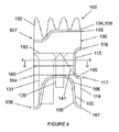
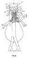
ここで図9〜図16を参照すると、第一の端部207および第二の端部209を有するルーメンを画定するステントグラフト本体205を含むステントグラフト200が示されている。一実施形態において、ステントグラフト本体205の第一の端部207は、留置の際に、ステントグラフト本体205の第二の端部209または先端よりも患者の心臓に近い位置になるように構成されたステントグラフト200の基端であり得る。隔膜210は、ルーメン内のある位置、または第一の端部207もしくは第二の端部209で、ステントグラフト本体205に連結され得る。一実施形態において、隔膜210は、ステントグラフト本体205の第二の端部または先端209からステントグラフト本体205の中央区分までの範囲のある位置で、ステントグラフト本体205に連結され得る。この配列は、有益には、血流からの圧力を隔膜の上のステントグラフト本体の近位側壁で作用させることができ、留置されるルーメンへのステントグラフトの封着および固定を支援し得る。
Here, with reference to FIGS. 9-16, a
隔膜210は、少なくとも3つの開口部を画定する。例えば一実施形態において、隔膜210は、第一のステントグラフト延在部231に連結された第一の開口部230と、第二のステントグラフト延在部236に連結された第二の開口部235と、第三のステントグラフト延在部221に連結された第三の開口部220と、第四のステントグラフト延在部226に連結された第四の開口部225と、を画定し得る。様々な実施形態において、第一の開口部230は、大動脈または他の天然の血管の腎臓下区分における配置でブリッジングステントを受けるために用いられ得、第二の開口部235は、腹腔およびSMAまたは他の天然の血管における配置でブリッジングステントを受けるために用いられ得、第三および第四の開口部220、225は、腎動脈または他の天然の血管における配置でブリッジングステントを受けるために用いられ得る。あるいは第一の開口部230は、大動脈弓における配置でブリッジングステントを受けるために用いられ得、第二の開口部235は、無名血管(右総頸動脈および右鎖骨下動脈)または他の天然の血管における配置でブリッジングステントを受けるために用いられ得、第三および第四の開口部220、225は、左総頸動脈および左鎖骨下動脈または他の天然の血管における配置でブリッジングステントを受けるために用いられ得る。
The
図11に示される一実施形態において、第一の開口部230は、第二の開口部235の直径よりも大きな直径を有し得る。図11に示された別の実施形態において、第二の開口部235の直径は、第三の開口部220の直径および第四の開口部225の直径よりも大きくなり得る。図9および図14に示される代わりの実施形態において、第二の開口部235、第三の開口部220および第四の開口部225は、それぞれ同じサイズの直径を有し得る。図11に示されたさらに別の実施形態において、第一の開口部230および第二の開口部235は、隔膜210内の対向する側で画定され得る。さらなる実施形態において、第一の開口部230、第二の開口部235、第三の開口部220および第四の開口部225は、それぞれ図11に示される通り、隔膜210の異なる四分円211〜214内で画定され得る。
In one embodiment shown in FIG. 11, the
図9、図14および図16に示されたさらなる実施形態において、第五の開口部237もまた、隔膜210において画定され得、第五のステントグラフト延在部238に連結され得る。一実施形態において、第五の開口部237は、腹腔およびSMAまたは他の天然の血管における配置でブリッジングステントを受けるために用いられ得る。一実施形態において、第一の開口部230は、第二の開口部235の直径および第五の開口部237の直径よりも大きな直径を有し得る(図9、図14および図16参照)。図16に示されたさらなる実施形態において、第二の開口部235の直径および第五の開口部237の直径は、第三の開口部220の直径および第四の開口部225の直径よりも大きくなり得る。図9および図14に示された通り代わりの実施形態において、第二の開口部235の直径および第五の開口部237の直径は、第三の開口部220の直径および第四の開口部225の直径と同じ寸法を有し得る。一実施形態において、図16に示された通り、第一の開口部230、第二の開口部235および第五の開口部237は、隔膜210内で直線上に配列され得、第三の開口部220および第四の開口部225は、第一、第二および第五の開口部230、235、237を中心として、対向する側に配列され得る。加えて、図9に示される通り、第三の開口部220および第四の開口部225は、互いに隣接して配列され得、隔膜210内の第一の開口部230とは対向する側で一緒に配列され得る。さらに一実施形態において、図14に示される通り、第一の開口部230は、隔膜210の第一の四分円211内に配列され得、第三の開口部220は、隔膜の第二の四分円212内に配列され得、第二の開口部235および第五の開口部237は、隔膜の第三の四分円213内に配列され得、第四の開口部225は、隔膜210の第四の四分円214内に配列され得る。
In the further embodiments shown in FIGS. 9, 14 and 16, the
さらに別の実施形態において、隔膜210の少なくとも一部が、ステントグラフト本体205の側壁218に関して、ステントグラフト本体205の第二の端部209に向かって角度を成し得る。図9〜図10に示された通り、一実施形態において、隔膜210の開口部220、225、230は、隔膜210の中心において画定され得、隔膜210は、実質的に漏斗の形状であり得る。さらなる実施形態において、ステントグラフト延在部の少なくとも1つの端部は、本発明の第一の態様に関して図示および記載される通り、隔膜210に隣接して先細になり得る。この配列は、延在部またはブリッジングステントを配置するために、ガイドワイヤーのアラインメントおよびステントグラフト延在部の各ルーメンへの進入を支援し得、層流の血流を促進し得る。
In yet another embodiment, at least a portion of the
加えて一実施形態において、隔膜210の開口部は、例えばブリッジングステントまたは延在部のステントグラフトとの嵌合を強化し得る。強化材料としては、ニチノール、例えば生体適合性である任意の非拡張性で折畳み可能な材料を挙げることができる。さらなる実施形態において、隔膜210は、本発明の第一の態様に関して述べた通り、ステントグラフト本体205に対して外向きの半径方向力を加えるように構成され得る拡張性フレームを有し得る。このフレームは、血管ルーメンとの固定および封着を支援し得る。
In addition, in one embodiment, the opening of the
一実施形態において、ステントグラフト本体205の直径は、約20mm〜約65mmの範囲内であり得、好ましくは内臓区分では約23mm〜約40mmまたは約28mm〜約36mm、好ましくは胸部大動脈では約30mm〜約65mmまたは約40mm〜約55mmの範囲内であり得る。加えて、ステントグラフト本体205の長さは、約10mm〜約150mm、好ましくは約20mm〜約60mmの範囲内であり得る。さらに、第二のステントグラフト延在部236および第五のステントグラフト延在部238のそれぞれが、一例において、約0.5mm〜約40mmの範囲内の長さを有し得る。さらに別の実施形態において、第二のステントグラフト延在部236の直径および第五のステントグラフト延在部238の直径のそれぞれが、約6mm〜約14mmの範囲内であり得る。
In one embodiment, the diameter of the
一実施形態において、第一のステントグラフト延在部231は、少なくとも30mmの長さを有し得、約8mm〜約25mmの範囲内の直径を有し得る。別の実施形態において、第一の開口部230は、約8mm〜約25mmの範囲内の直径を有し得る。さらなる実施形態において、第三の開口部220および第四の開口部225はそれぞれ、約4mm〜約25mmの範囲内の直径を有し得る。別の実施形態において、第三のステントグラフト延在部221および第四のステントグラフト延在部226はそれぞれ、約4mm〜約12mmの範囲内の直径を有し得る。
In one embodiment, the first
ステントグラフト200はまた、本発明の第一の態様に関して先に述べた通り、ステントグラフト本体205に連結された複数の封着リングを含み得る。例えば一実施形態において、複数の封着リングは、ステントグラフト本体205に連結された、または第一の端部207に直接隣接する、近位封着リング245を含み得る。一実施形態において、近位封着リング245は、上部および下部を画定する二段構造を有し得る。代わりの実施形態において、近位封着リングは、リング状であり得る。
The
図13Bおよび図23に示される一実施形態において、ステントグラフトは、ステントグラフト本体205の側壁において画定される逆U形を有し、隔膜210からステントグラフト本体205の第二の端部209まで延在する、内臓−血管開口部275を含み得る。内臓開口部は、有利には血流の遮断を回避し、腹腔およびSMA動脈へのアクセスを可能にし得る。さらなる実施形態において、複数の封着リングは、隔膜210とステントグラフト本体205の第二の端部209の間でステントグラフト本体205に連結された遠位封着リング176を含み得る。遠位封着リング276は、ステントグラフト本体205の円周の一部の周りに配列された放射状部分277と、内臓−血管開口部275とアライメントされた弓部278と、を有し得る。一実施形態において、遠位封着リング276の放射状部分277の各端部は、それぞれが約20mm〜約50mmの範囲内の曲線半径を有する2つの曲線区分279を介して、弓部278に移行し得る。さらに別の実施形態において、第一の端部207と隔膜210の間のステントグラフト本体205の長さは、約10mm〜約150mmの範囲内であり得る。さらなる実施形態において、隔膜210からステントグラフト本体205の第二の端部209までのステントグラフト本体205の長さは、約0.05mm〜約40mmの範囲内であり得る。
In one embodiment shown in FIGS. 13B and 23, the stent graft has an inverted U shape defined on the side wall of the
別の実施形態において、本発明の第二の態様に関して以下で述べる通り、一対の向かい合うらせん状ステント構造は、第一のステントグラフト延在部231、第二のステントグラフト延在部236、第三のステントグラフト延在部221、第四のステントグラフト延在部226および第五のステントグラフト延在部238のうちの1つまたは複数に連結され得る。
In another embodiment, as described below with respect to a second aspect of the invention, the pair of opposing helical stent structures comprises a first
さらに別の実施形態において、ステントグラフト本体205の第一の端部207は、本発明の第二の態様に関して以下に記載される通り、固定ステントに連結され得る。
In yet another embodiment, the
図19に示された代わりの実施形態において、ステントグラフトは、ステントグラフト本体205の第一の端部207に付着されたステントバルブ280を含み得る。この配列において、ステントバルブの自由端は、被覆され得、該自由端とステントグラフト本体205の間を延在するステントバルブの一部は、非被覆であり得る。本明細書で用いられる「ステントバルブ」は、血流を維持するために冠動脈に重なる非被覆部分によってステントグラフト本体205の基端または第一の端部207に付着された経皮自己拡張型バルブである。ステントバルブの模範的実施形態としては、Medtronicによって製造されるCorevalve(登録商標)が挙げられる。一実施形態において、ステントバルブの自由端は、不浸透性天然または合成材料で被覆され得る。一実施形態において、ステントバルブは、大動脈弁の流出管の中に配置され得る。ステントバルブ定着機構は、例えば、自由端でより大きな直径を有し、被覆部分が非被覆部分と出会うポイントでより小さな直径を有する、漏斗形から得られる。
In an alternative embodiment shown in FIG. 19, the stent graft may include a
第二の態様において、該ステントグラフトは、
第一の端部および第二の端部を有するルーメンを画定するステントグラフト本体と、
該ステントグラフト本体に連結され、少なくとも3つの開口部を画定する隔膜と、
それぞれがルーメンを画定する少なくとも3つのステントグラフト延在部であって、該少なくとも3つのステントグラフト延在部のそれぞれの第一の端部が該少なくとも3つの開口部の1つに連結されている、少なくとも3つのステントグラフト延在部と、
該ステントグラフト本体の該第一端部と該第二の端部の間にある該ステントグラフト本体の側壁において画定される内臓−血管開口部であって、該隔膜が該ステントグラフト本体のルーメン内に配設され、該隔膜の少なくとも3つの開口部が第一の開口部、第二の開口部、第三の開口部および第四の開口部を含む、内臓−血管開口部と、
第二の開口部および該隔膜のうちの一方に、そして該内臓−血管開口部および該ステントグラフト本体の側壁のうちの一方に連結された側壁によって画定される内臓空洞と、
を提供する。
In the second aspect, the stent graft is
A stent graft body that defines a lumen with a first end and a second end,
A diaphragm that is connected to the stent graft body and defines at least three openings.
At least three stent graft extensions, each defining a lumen, with the first end of each of the at least three stent graft extensions connected to one of the at least three openings. Three stent graft extension parts and
A visceral-vascular opening defined on the side wall of the stent graft body between the first end and the second end of the stent graft body, wherein the diaphragm is disposed within the lumen of the stent graft body. And a visceral-vascular opening, wherein at least three openings in the diaphragm include a first opening, a second opening, a third opening and a fourth opening.
A visceral cavity defined by a side wall connected to a second opening and one of the diaphragms, and to one of the visceral-vascular opening and the side wall of the stent graft body.
I will provide a.
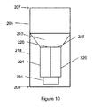
ここで図1〜図6を参照すると、ステントグラフト本体105の第一の端部または基端107で画定される入口106を有し、ステントグラフト本体105の第二の端部または先端109で画定される出口108を有する、ルーメンを画定するステントグラフト本体105を含むステントグラフト100が、示される。一実施形態において、隔膜110とステントグラフト本体105の基端107の間に配列されるステントグラフト本体105のルーメンの一部は、約20mm〜約65mm、好ましくは約20mm〜約46mmの範囲内の直径を有し得る。別の実施形態において、ステントグラフト本体105は、約10mm〜約150mmの範囲内の長さを有して、ステントグラフト本体105の第一の端部107と、内臓−血管開口部115の第一の端部116の間を延在し得る。さらなる実施形態において、ステントグラフト本体105は、0mm〜約40mmの範囲内の長さを有して、内臓−血管開口部115の第二の端部または先端117と、ステントグラフト本体105の第二の端部109の間を延在し得る。
Here, referring to FIGS. 1 to 6, it has an inlet 106 defined by the first end or
ステントグラフト100は、ステントグラフト本体105のルーメン内に配設され、ステントグラフト本体105に連結された隔膜110を含む。隔膜110は、第一の開口部130、第二の開口部135、第三の開口部120および第四の開口部125を画定する。一実施形態において、第一の開口部130は、腎臓下区分をステント設置するために用いられ得、第二の開口部135は、腹腔およびSMA動脈をステント設置するために用いられ得、第三の開口部120および第四の開口部125は、腎動脈をステント設置するために用いられ得る。第二の開口部135は、以下により詳細に述べる内臓−血管開口部115の上に横たわる隔膜110の四分円の中にアライメントされ得、第一の開口部130ならびに第三および第四の開口部120、125は、隔膜110の同じまたは他の四分円内で様々な構成で配列され得る。例えば一実施形態において、図6に示される通り、第一の開口部130および第二の開口部135は、隔膜110内の対向する側に配列され得、第三の開口部120および第四の開口部125も同様に、第一の開口部130と第二の開口部135の間の隔膜110内の対向する側に配列され得る。あるいは第三および第四の開口部120、125は、第一の開口部130と第二の開口部135の間の隔膜110内の同じ側に配列され得る。他の実施形態において、第一の開口部130、ならびに第三および第四の開口部120、125のうちの一方は、他方の開口部がそれらの間に配列され得る隔膜110とは対向する側に配列され得る。さらなる実施形態において、第二の開口部135の直接対向する側に他の入口が存在しないように、第一の開口部130、ならびに第三および第四の開口部120、125が配列され得る。
The
一実施形態において、隔膜110は、これらの様々な開口部を取り囲む領域内で傾斜し得るか、または先細になり得る。一実施形態において、第二の開口部135は、数ある可能性の中で、約5mm〜約15mmの範囲内の半径を有するV形半円の開口部として、または約6mm〜約20mmの範囲内の直径を有する全円の開口部として画定され得る。さらなる実施形態において、第三の開口部120、第四の開口部125、第一の開口部130は、実質的に円形を有し得る。一実施形態において、3つのステントグラフト延在部121、126および131は、ステントグラフト100の留置前に液密(血液密封)の手法で、それぞれ第三の開口部120、第四の開口部125および第一の開口部130に直接連結され得る。これらのステントグラフト延在部121、126、131はそれぞれ、ルーメンを画定し、受動的または能動的な固定を介して適所に保持され得る拡張またはブリッジングステントグラフトを受けるように構成される。この配列は、ステントグラフト100と腎動脈の間に血流を提供し得、そして/または例えば大動脈および総腸骨動脈を含む腎臓下動脈に血流を提供し得る。
In one embodiment, the
様々な実施形態において、ステントグラフト延在部121、126、131は、真直ぐであり得るか、または徐々に広がり得、遠位自由端123、128、133は、ブリッジングステントグラフトを配置するために自由に移動可能であり得る。一実施形態において、第一の開口部130に連結されたステントグラフト延在部131は、少なくとも30mmの長さを有し得、別の実施形態において、約10mm〜120mmの範囲内の長さを有し得る。そして別の実施形態において、ステントグラフト延在部131は、約8mm〜約25mmの範囲内の直径を有し得る。別の実施形態において、第一の開口部130は、約8mm〜約25mmの範囲内の直径を有し得る。さらに別の実施形態において、ステントグラフト延在部131の第一の端部または基端が、先細132になるように、第一の開口部130の直径は、連結されたステントグラフト延在部131の直径よりも大きくなり得る。別の実施形態において、第三および第四の開口部120、125はそれぞれ、約4mm〜約25mmの範囲内の直径を有し得る。一実施形態において、第三および第四の開口部に連結されたステントグラフト延在部121、126はそれぞれ、約4mm〜約18mmの範囲内の直径を有し得る。さらに別の実施形態において、ステントグラフト延在部121、126それぞれの第一の端部または基端が、先細122、127になるように、第三および第四の開口部120、125それぞれの直径は、ステントグラフト延在部121、126のそれぞれの直径よりも大きくなり得る。隔膜開口部から様々なステントグラフト延在部まで先細になることが、拡張またはブリッジングステントを配置するためのガイドワイヤーのアラインメントおよび各ルーメンへの進入を支援し得、層流の血流を促進し得る。別の実施形態において、ステントグラフト延在部121、126および131は、留置後に別々に配置され得る。この実施形態において、ステントグラフト延在部121、126、131は、留置により隔膜の近位に配列される、裾の広がった基端を有し得る。
In various embodiments, the
一実施形態において、一対の向かい合うらせん状のステント構造が、ステントグラフト延在部121、126および131のうちの1つまたは複数に連結されて、その長さに沿って延在し得る。らせん状ステント構造は、有利にはルーメンの伸長を予防し得る。これらのらせん状ステント構造は、数ある可能性の中で、ニチノールなどの弾性形状記憶、ステンレス鋼、プラスチック、ポリマーまたはそれらの材料の任意の組み合わせを有する生体適合性材料から作製され得る。
In one embodiment, a pair of opposing helical stent structures may be connected to one or more of the
さらなる実施形態において、本開示の第一、第二および第三の態様によれば、隔膜110は、拡張性フレーム111を有し得る。この拡張性フレーム111は、隔膜110に適用される下向きの力に対して、ステントグラフト本体105の外向きの半径方向力を加えるように構成され得る。下向きの力は、例えば血流によるものであり得る。一実施形態において、隔膜110は、内臓−血管開口部115の第一の端部116と、内臓−血管開口部115の第二の端部117で、またはそれらの間で、ステントグラフト本体105のルーメン内に位置し得る。
In a further embodiment, according to the first, second and third aspects of the present disclosure, the
ステントグラフト100はまた、ステントグラフト本体105の第一の端部107と第二の端部109の間のステントグラフト本体105の側壁118において画定される内臓−血管開口部115を含む。一実施形態において、内臓−血管開口部115は、約10mm〜約60mmの範囲内の高さを有し得、約5mm〜約30mmの範囲内の幅を有し得る。一実施形態において、内臓−血管開口部は、第二の端部または先端よりも第一の端部または基端が広くなり得、内臓−血管開口部115と2つの腎臓開口部170の間により大きなグラフト表面積を提供して、ステントグラフトと血管構造の間により強固な封着を提供し得る。別の実施形態において、内臓−血管開口部115は、分流材料、例えば高打込み密度の結われた、または織られた自己拡張型ステント材料で被覆され得る。この分流材料は、例えば、血管構造内の腎動脈上ステントグラフトの定着および封着を支援するためにステント設置されていない大動脈壁の度合いを最小限にしながら、内臓血管への開存性を可能にし得る。これは、ステントグラフトと大動脈のより強固な封着を提供し得る。該分流材料は、血栓の形成およびそこからの動脈発生も可能にし得、ステントグラフト本体105のこの領域を通る適当な血流および血圧を支援し得る。
The
加えて、ステントグラフト100は、隔膜110および第二の開口部135のうちの一方に、そしてステントグラフト本体の側壁および内臓−血管開口部のうちの一方に連結された側壁141によって画定される内臓空洞140を含む。内臓空洞140は、SMAおよび腹腔動脈へ血流を提供し得る。加えて、外科医は、内臓空洞140を利用して、SMAおよび/または腹腔動脈におけるブリッジングステントを配置し得る。
In addition, the
一実施形態において、ステントグラフト100は、ステントグラフト本体105に連結された複数の封着リングをさらに含み得る。別の実施形態において、複数の封着リングは、ステントグラフト本体105の第一の端部107に、または第一の端部107に直接隣接して、ステントグラフト本体105に連結された近位封着リング145を含み得る。さらなる実施形態において、近位封着リング145は、上部146および下部147を画定する二段構造を有し得る。近位封着リング145の下部147は、内臓−血管開口部115とアライメントされて、その近位に配列され得、下部147は、近位封着リング145の上部146に対して遠位に配列され得る。一実施形態において、近位封着リング145の上部146は、約0mm〜約40mmの範囲内の距離だけ、ステントグラフト本体105に沿って下部147から長手方向に離れ得る。二段の実施形態において、ステントグラフト本体105の第一の端部107の周縁部104は、近位封着リング145と同じ二段の外形を有し得る。一実施形態において、ステントグラフト本体105は、約0mm〜約20mmの範囲内の長さを有し得、ステントグラフト本体105の近位封着リング145の下部147と、内臓−血管開口部115の第一の端部1116の間で延在し得る。
In one embodiment, the
ステントグラフト本体105のグラフト材料は、血液を脊柱へ送達する腰部動脈の被覆を回避するために、近位封着リング145と同じ境界を有し得る。他の実施形態において、グラフト材料は、近位封着リング145の上部境界に沿って均一な円周を有し得る。さらなる実施形態において、該グラフト材料は、近位封着リング145の上部近位境界を越えて、固定ステント150の最上部または近位縁部まで延在し得る。
The graft material of the
別の実施形態において、内臓−血管封着リング155が、内臓−血管開口部115を取り囲むように、複数の封着リングが、ステントグラフト本体105に連結された内臓−血管封着リング155を含み得る。例えば内臓−血管封着リング155は、留置の際に内臓−血管開口部115を無傷に保つ円周力を加えて、SMAおよび腹腔動脈の周りに緊密な液密を提供し得る。少なくとも1つの支持封着リング160の第一の端部161が、内臓−血管封着リング155の第一の側に連結され、少なくとも1つの支持封着リング155の第二の端部162が、内臓−血管封着リング155の第二の側に連結されるように、複数の封着リングも、ステントグラフト本体105に連結された少なくとも1つの支持封着リング160を含み得る。内臓−血管封着リング155はまた、支持封着リング160と協同で働き、ステントグラフト本体105に対して円周の半径方向力を提供して、例えば大動脈との液密(即ち、血液密封)を提供し得る。さらなる実施形態において、少なくとも1つの支持封着リング160は、近位支持封着リング163、遠位支持封着リング164、および中央支持封着リング160を含み得る。一実施形態において、中央支持封着リング160は、内臓−血管封着リング155に連結され得る。近位支持封着リング163は、ステントグラフト本体105の第一の端部107と、中央支持封着リング160の間で、ステントグラフト本体105に連結され得る。そして遠位支持封着リング164は、ステントグラフト本体105の第二の端部109と、中央支持封着リング160の間で、ステントグラフト本体105に連結され得る。
In another embodiment, a plurality of sealing rings may include a visceral-
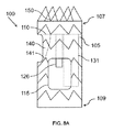
さらに別の実施形態において、複数の封着リングは、ステントグラフト本体105の第二の端部109に、または第二の端部109に直接隣接して、ステントグラフト本体105に連結された遠位封着リング165を含み得る。一実施形態において、2つの腎臓開口部170は、隔膜110に対して遠位のステントグラフト本体105の側壁118において画定され得る。一実施形態において、遠位封着リング165は、2つの弓部167によって接合された2つの半径部分166を有し得る。2つの弓部167は、ステントグラフト本体105の側壁118に沿って長手方向に配列され得、2つの半径部分166は、ステントグラフト本体105の円周の周りに配列され得る。2つの弓部167は、2つの腎臓開口部170とアライメントされている。一実施形態において、遠位封着リング165の2つの半径部分166の間を延在する有効直径は、約20mm〜約50mmの範囲内であり得る。一実施形態において、2つの弓部167は、約4mm〜約30mmの範囲内の幅を有し得る。腎臓開口部170がステントグラフト本体105の側壁118内に提供されていない実施形態において、ステントグラフト本体105の長さは、短縮されて、腎臓ステントグラフトを第二の端部から出すことができ、それによりそれらは、ブリッジングステントが配置されると、腎臓入口および標的血管の小孔からの曲線の緩やかな広がりまたは大きな半径を有することができる。図7A〜図8Bに示されたさらに別の実施形態において、ステントグラフト本体の側壁の2つの腎臓開口部170は、フェネストレーションのサイズおよび形状であり得、天然の動脈へのアクセスを可能にし得る。
In yet another embodiment, the plurality of sealing rings are distal seals connected to the
本開示の第一、第二および第三の態様に適用可能な一実施形態において、ブリッジングステントグラフトは、らせん形状のブリッジングステントグラフトの長さに沿って長手方向に、そして対向する側に配設された2つのワイヤーに連結された離れたステントリングを含み得る。この配列は、有益にはブリッジングステントグラフトの伸長を予防し得る。第三および第四の開口部120、125に連結されたステントグラフト延在部121、126、または第一の開口部130に連結されたステントグラフト延在部131との適当な重複は、ステントグラフトデブランチング手順の際にブリッジングステントグラフトと受動的な固定を実現するのに十分になり得る。例えば能動的な固定の特色もステントグラフトで用いられる場合には、この重複領域の長さはより短くなり得る。
In one embodiment applicable to the first, second and third aspects of the present disclosure, the bridging stent graft is disposed longitudinally along the length of the spiral bridging stent graft and on opposite sides. It may include a distant stent ring connected to the two wires. This sequence can beneficially prevent elongation of the bridging stent graft. Appropriate overlap with the
第三の態様において、該ステントグラフトは、
第一の端部および第二の端部を有するルーメンを画定するステントグラフト本体と、
該ステントグラフト本体に連結され、少なくとも3つの開口部を画定する隔膜と、
それぞれがルーメンを画定する少なくとも3つのステントグラフト延在部であって、該少なくとも3つのステントグラフト延在部のそれぞれの第一の端部が該少なくとも3つの開口部の1つに連結されている、少なくとも3つのステントグラフト延在部と、
該ステントグラフト本体の該第一端部と該第二の端部の間にある該ステントグラフト本体の側壁において画定される内臓−血管開口部であって、該隔膜が該ステントグラフト本体のルーメン内に配設され、該隔膜の少なくとも3つの開口部が第一の開口部、第二の開口部、第三の開口部および第四の開口部を含む、内臓−血管開口部と、
を提供する。
In a third aspect, the stent graft is
A stent graft body that defines a lumen with a first end and a second end,
A diaphragm that is connected to the stent graft body and defines at least three openings.
At least three stent graft extensions, each defining a lumen, with the first end of each of the at least three stent graft extensions connected to one of the at least three openings. Three stent graft extension parts and
A visceral-vascular opening defined on the side wall of the stent graft body between the first end and the second end of the stent graft body, wherein the diaphragm is disposed within the lumen of the stent graft body. And a visceral-vascular opening, wherein at least three openings in the diaphragm include a first opening, a second opening, a third opening and a fourth opening.
I will provide a.
ここで図7Aおよび図7Bを参照すると、一実施形態において、それぞれ基端および先端に対応し得る第一の端部107および第二の端部109を有するルーメンを画定するステントグラフト本体105を含むステントグラフト100が示されている。内臓−血管開口部115は、ステントグラフト本体105の第一の端部107と、第二の端部109の間でステントグラフト本体105の側壁において画定される。加えて、隔膜110は、ステントグラフト本体105のルーメン内に配設され、ステントグラフト本体105に連結される。隔膜は、第一の開口部、第二の開口部、第三の開口部および第四の開口部を画定する。一実施形態において、開口部のそれぞれは、例えばブリッジングステントを受け得、腎臓下区分を第一の開口部130に連結し得、腹腔およびSMA動脈を第二の開口部135に連結し得、腎動脈を第三および第四の開口部120、125に連結し得る。
Referring now to FIGS. 7A and 7B, in one embodiment, a stent graft comprising a
一実施形態において、内臓空洞140は、隔膜110と、ステントグラフト本体105の側壁と、隔膜110とステントグラフト本体105の側壁の間を延在する内臓側壁141と、によって画定され得る。別の実施形態において、第五の開口部137は、内臓側壁と、ステントグラフト本体105の側壁の間の隔膜において画定される。この第五の開口部137は、有益には腹腔およびSMA動脈への血流を可能にしながら、第二の開口部を能動的にステント設置するか、または他の方法で遮断し、そしてその逆もあり得る。第五の開口部137はまた、腹腔およびSMA動脈の1つよりも多くをステントグラフトで橋渡しし得る。
In one embodiment, the
第二および第五の開口部135、137は、内臓側壁141とステントグラフト本体105の側壁の間の隔膜110において画定される。内臓側壁141は、ステントグラフト本体105の第二の端部109と隔膜110の間で画定される内臓−血管開口部115の一部を取り囲む。
The second and
一実施形態において、第二の開口部135および第五の開口部137は、互いに隣接して配列され得る。別の実施形態において、第二の開口部135は、ルーメンを画定するステントグラフト延在部136に連結され得、第五の開口部137もまた、ルーメンを画定するステントグラフト延在部138に連結され得る。さらなる実施形態において、第二および第五の開口部の一方に連結されたステントグラフト延在部のそれぞれは、約6mm〜約14mmの範囲内の直径を有し得、約0.5mm〜約40mmの範囲内の長さを有し得る。
In one embodiment, the
さらなる実施形態において、第一の開口部120、第二の開口部135、第三の開口部120、第四の開口部125および第五の開口部137のうちの1つまたは複数は、強化され得る。
In a further embodiment, one or more of the
図24に示され、本開示の態様の全てに適用可能である一実施形態において、ステントグラフト300は、それぞれが小穴を画定する複数のアンカー385を含む。複数のアンカー385は、ステントグラフト本体305に沿って長手方向に間隔をおいて配列される。さらなる実施形態において、ステントグラフト300は、第一の端部387および第二の端部388を有する糸386を含む。ステントグラフト本体305が、一部拡張された状態および完全に拡張された状態を有するように、糸386は、複数のアンカー385の小穴を通して摺動自在に配列され得る。一部拡張された状態では、糸386は、緊張下にあり得、糸の第一の端部387は、複数のアンカー385の第一のアンカー390に固定して連結され得、糸386の第二の端部388は、複数のアンカーの第二のアンカー391に着脱自在に連結され得る。完全に拡張された状態では(図24参照)、糸388の第二の端部は、第二のアンカー391から開放され得、糸386は、緊張され得ない。
In one embodiment, shown in FIG. 24 and applicable to all aspects of the present disclosure, the
一実施形態において、ステントグラフト本体305は、一部拡張された状態では完全に拡張された直径の50%〜95%で拡張し得る。そのようにして一部拡張された状態は、ステントグラフトをルーメン内に留置させ、その後再度、位置決めされ得る。例えば一部拡張されたステントグラフトのより小さな直径によって、適当な分岐血管構造とのアラインメントのために、ステントグラフトをルーメンの所望の位置より近位および遠位に移動させ、回転させ得る。適所になると、糸386の着脱自在の端部388は、以下に記載された通りアンカー391から分離され得、ステントグラフト300は、例えばステントの形状記憶またはバルーン拡張によって完全に拡張された状態に移行し得る。
In one embodiment, the
別の実施形態において、複数のアンカーは、内臓−血管開口部に対向するステントグラフト本体の側に配列され得る。さらなる実施形態において、複数のアンカーは、横方向の向かい合う対として配列され得る(図24参照)。さらなる実施形態において、複数のアンカーは、ジグザグパターンで配列され得る。 In another embodiment, the plurality of anchors may be arranged on the side of the stent graft body facing the visceral-vascular opening. In a further embodiment, the plurality of anchors can be arranged as opposite lateral pairs (see FIG. 24). In a further embodiment, the plurality of anchors can be arranged in a zigzag pattern.
一実施形態において、複数のアンカー385の小穴および糸386は、低摩擦材料で作製され得、ステントグラフト300を一部拡張された状態から完全に拡張された状態へ移行させる。
In one embodiment, the pores and
本開示のステントグラフトは、非限定的に、放射線不透過性マーカーをはじめとする任意のさらなる適切な成分を含有して視覚化を支援し、ステントグラフトの正確な配置を促進し得る。これらの放射線不透過性マーカーは、ステントグラフトの方向および方位を示すために、例えば「S」の形状または任意の他の適切な形態で、所与のステントグラフトの個々のルーメンの先端にあるゴールドバンドの形態または他の指向性マーカーの形態をとり得る。一実施形態において、ステントグラフト本体105の第一の端部または基端107、207は、固定ステント150に連結され得る。加えて、固定ステント150の一部は、血管壁の非患部において信頼できる手掛かりを得るのに用いられ得るため、二方向性定着フックが、形成され得る。この固定ステント150は、二方向性フックと併せて血管内での半径方向力での固定を提供し得る。別の実施形態において、固定ステント150は、ステントグラフト本体105のルーメンから離れるように偏向されて、動脈瘤が近位に進行した場合でも血管構造との固定を留置状態に維持し得る。
The stent grafts of the present disclosure may contain any additional suitable components, including, but not limited to, radiopaque markers to aid visualization and facilitate accurate placement of the stent graft. These radiation opaque markers, for example in the shape of an "S" or in any other suitable form, of a gold band at the tip of each lumen of a given stent graft to indicate the orientation and orientation of the stent graft. It can take the form of a morphology or other directional marker. In one embodiment, the first or proximal ends 107, 207 of the
第四の態様において、本発明は、本発明の第一の態様によるステントグラフト100の配置の方法を提供する。該方法は、(a)動脈アクセスを介して任意の適当なサイズの動脈構成の中にガイドワイヤーを導入すること、(b)前述の実施形態のいずれかによるステントグラフトを含む送達カテーテルをガイドワイヤー上へロードすること、(c)該ガイドワイヤーに沿って該送達カテーテルを移動させて、動脈アクセスを介して該適当なサイズの動脈構成の中に該送達カテーテルを導入すること、ならびに(d)該ステントグラフトを該適当なサイズの動脈構成および/または過去に配置されたステントグラフトのルーメンの中へ留置すること、を含む。
In a fourth aspect, the present invention provides a method of arranging the
一実施形態において、該方法は、それぞれが小穴を画定する複数のアンカーを通して配列された緊張した糸を介して、ステントグラフトを一部圧縮された状態に維持することをさらに含み得る。一実施形態において、糸の緊張は、複数のアンカーの第一のアンカーからワイヤーの一端を開放することにより低減され得る。糸の緊張が低減されると、その後ステントグラフトは、完全に拡張された状態に拡張され得る。 In one embodiment, the method may further comprise maintaining the stent graft in a partially compressed state via a toned thread, each arranged through a plurality of anchors defining a small hole. In one embodiment, thread tension can be reduced by opening one end of the wire from the first anchors of the plurality of anchors. Once the thread tension is reduced, the stent graft can then be expanded to a fully expanded state.
一実施形態において、第二の態様は、(e)ブリッジングステントグラフトを含む第二の送達カテーテルをガイドワイヤー上にロードすること、(f)ガイドワイヤーに沿って第二の送達カテーテルを移動させて、動脈アクセスを介してステントグラフト105の本体のルーメンの基端107の中に第二の送達カテーテルを導入すること、(g)隔膜110において画定される第一の腎臓入口120、第二の腎臓入口125、腎臓下入口130または内臓入口135の中から選択すること、(h)選択された入口の中へ、そして選択された入口に連結されたルーメン121、126、131または適切なサイズの動脈ルーメンのいずれかの中へ、第二の送達カテーテルを導入すること、および(i)選択された入口または適切なサイズの動脈ルーメンの中へブリッジングステントグラフトの全てまたは一部を留置すること、をさらに含み得る。
In one embodiment, the second aspect is (e) loading a second delivery catheter, including a bridging stent graft, onto a guidewire, (f) moving the second delivery catheter along the guidewire. Introducing a second delivery catheter into the
第五の態様において、ステントグラフトは、
第一の端部および第二の端部を有するルーメンを画定するステントグラフト本体と、
該ステントグラフト本体に連結され、第一の開口部、第二の開口部、および第三の開口部を画定する隔膜と、
第一の端部および第二の端部を有する第一のステントグラフト延在部であって、該第一のステントグラフト延在部が単一ルーメンを有し、該第一のステントグラフト延在部の該第一の端部が該隔膜に連結されて、該第一の開口部を取り囲んで配列された、第一のステントグラフト延在部と、
第一の端部および第二の端部を有する第二のステントグラフト延在部であって、該第二のステントグラフト延在部が、該第一の端部で単一ルーメンを有し、該第二の端部で2つのルーメンを画定する分岐点を有し、該第二のステントグラフト延在部の該第一の端部が該隔膜に連結され、該第二の開口部を取り囲んで配列された、第二のステントグラフト延在部と、
第一の端部および第二の端部を有する第三のステントグラフト延在部であって、該第三のステントグラフト延在部が該第一の端部で単一ルーメンを有し、該第三のステントグラフト延在部の該第一の端部が該隔膜に連結され、該第三の開口部を取り囲んで配列された、第三のステントグラフト延在部と、
を提供する。
In a fifth aspect, the stent graft is
A stent graft body that defines a lumen with a first end and a second end,
A diaphragm connected to the stent graft body and defining a first opening, a second opening, and a third opening.
A first stent graft extension having a first end and a second end, wherein the first stent graft extension has a single lumen and the first stent graft extension. A first stent graft extension, with a first end connected to the diaphragm and arranged surrounding the first opening.
A second stent graft extension having a first end and a second end, wherein the second stent graft extension has a single lumen at the first end and the first. It has a bifurcation that defines the two lumens at the two ends, the first end of the second stent graft extension is connected to the diaphragm and is arranged surrounding the second opening. And the second stent graft extension,
A third stent graft extension having a first end and a second end, wherein the third stent graft extension has a single lumen at the first end and said third. A third stent graft extension, wherein the first end of the stent graft extension is connected to the diaphragm and is arranged to surround the third opening.
I will provide a.
ここで、図25A〜図26Bを参照すると、第一の端部406および第二の端部407を有するルーメンを画定するステントグラフト本体405を有するステント400が示されている。ステントグラフト本体405に連結されるのは、第一の開口部415、第二の開口部420および第三の開口部425を画定する隔膜410である。第一のステントグラフト延在部430は、単一ルーメンを画定し、第一の端部431および第二の端部432を有し、第一のステントグラフト延在部430の第一の端部431は、隔膜410に連結され、第一の開口部415を取り囲んで配列される。第二のステントグラフト延在部435は、第一の端部436に単一ルーメンを有し、第二の端部438に2つのルーメンを画定する分岐点437を有する。第二のステントグラフト延在部435の第一の端部436は、隔膜410に連結され、第二の開口部420を取り囲んで配列される。そして第三のステントグラフト延在部440は、第一の端部441および第二の端部442を有する。第三のステントグラフト延在部440は、第一の端部441に単一ルーメンを有し、第三のステントグラフト延在部440の第一の端部441は、隔膜410に連結され、第三の開口部425を取り囲んで配列される。
Here, with reference to FIGS. 25A-26B, a
図26A〜図26Bに示される一実施形態において、第一の開口部415は、円形であり得、第二の開口部420は、楕円形であり得、第三の開口部425は、円形であり得る。この実施形態において、ステントグラフト400は、隔膜410において画定され、円形である第四の開口部445をさらに含み得る。そして第四のステントグラフト延在部450は、第一の端部451および第二の端部452を有し、第四のステントグラフト延在部450は、第一の端部451に単一ルーメンを有し、第四のステントグラフト延在部450の第一の端部451は、隔膜410連結され、第四の開口部445を取り囲んで配列される。一実施形態において、第三の開口部425および第四の開口部445は、互いに隣接して配列され得る。代わりの実施形態において(図示されない)、第一の開口部は、円形であり得、第二の開口部は、円形であり得、第三の開口部は、楕円形であり得る。さらなる実施形態において、第四の開口部は、隔膜において画定され得、円形である第二の開口部に隣接した位置にある。
In one embodiment shown in FIGS. 26A-26B, the
別の実施形態において、第一の開口部415は、円形であり、第二の開口部420は、楕円形であり、第三の開口部425は、楕円形である。第三のステントグラフト延在部440は、第二の端部442で2つのルーメンを画定する分岐点443を有し得る。一実施形態において、第二の開口部420は、第一の開口部415と第三の開口部425の間に配列される。さらなる実施形態において、第二の開口部420の長軸は、第三の開口部425の長軸と垂直に配列され得る。さらに別の実施形態において、第二の開口部420の短軸は、第三の開口部425の長軸とアラインメントされている。
In another embodiment, the
一実施形態において、第二のステントグラフト延在部435の2つのルーメンはそれぞれ、約4mm〜約12mmの範囲内の直径を有する。別の実施形態において、第二の開口部420の長軸は、約4mm〜約36mmの範囲内の長さを有し得、第二の開口部420の短軸は、約4mm〜約24mmの範囲内の長さを有し得る
In one embodiment, the two lumens of the second
別の実施形態において、第三のステントグラフト延在部440の2つのルーメンはそれぞれ、約6mm〜約14mmの範囲内の直径を有し得る。さらなる実施形態において、第三の開口部の長軸は、約6mm〜約42mmの範囲内の長さを有し、第三の開口部の短軸は、約6mm〜約28mmの範囲内の長さを有する。
In another embodiment, the two lumens of the third
さらなる実施形態において、第二のステントグラフト延在部435の分岐点437は、隔膜410から約0mm〜約50mmの範囲内の位置で発生し得、第三のステントグラフト延在部440の分岐点443は、隔膜410から約0mm〜約50mmの範囲内の位置に発生している。幾つかの実施形態において、隔膜から離れた分岐点の凹所が、屈伸可能なカテーテルチップを介して第二および第三のグラフト延在部の2つのルーメンの一方の選択を可能にする窪みを生成し得る。これが、ブリッジングステントを適所に進めるのにかかる時間の低減を支援し得、それにより手術の際にデバイスの配置を視覚化するのに用いられる蛍光および放射線の量を低減し得る。別の実施形態において、第一のステントグラフト延在部430、第二のステントグラフト延在部435、および第三のステントグラフト延在部440はそれぞれ、約5mm〜約50mmの範囲内の長さを有し得る。
In a further embodiment, the
一実施形態において、第二のステントグラフト延在部435の第一の端部438は、先細になっており、第三のステントグラフト延在部440の第一の端部441は、先細になっている。さらなる実施形態において、第一のステントグラフト延在部430の第一の端部431は、先細になっている。
In one embodiment, the
第六の態様において、ステントグラフトは、
第一の端部および第二の端部を有するルーメンを画定するステントグラフト本体と、
該ルーメン内で該ステントグラフト本体に連結され、少なくとも3つの開口部を画定する隔膜と、
それぞれがルーメンを画定する少なくとも3つのステントグラフト延在部であって、該少なくとも3つのステントグラフト延在部のそれぞれの第一の端部が該少なくとも3つの開口部の1つに連結されている、少なくとも3つのステントグラフト延在部と、
該ステントグラフト本体の側壁において画定される内臓−血管開口部と、
該隔膜に対して遠位の該ステントグラフト本体の側壁において画定される2つの腎臓開口部と、
該内臓−血管開口部および該2つの腎臓開口部のうちの少なくとも1つを被覆する透過性膜材料と、
を提供する。
In the sixth aspect, the stent graft is
A stent graft body that defines a lumen with a first end and a second end,
A diaphragm that is connected to the stent graft body within the lumen and defines at least three openings.
At least three stent graft extensions, each defining a lumen, with the first end of each of the at least three stent graft extensions connected to one of the at least three openings. Three stent graft extension parts and
Visceral-vascular openings defined on the sidewalls of the stent graft body,
Two kidney openings defined on the side wall of the stent graft body distal to the septum,
A permeable membrane material covering at least one of the visceral-vascular opening and the two kidney openings.
I will provide a.
ここで図27A〜図27Bを参照すると、第一の端部506および第二の端部507を有するルーメンを画定するステントグラフト本体505を有するステントグラフト500が示されている。隔膜510は、ルーメン内でステントグラフト本体505に連結され、隔膜510は、少なくとも3つの開口部を画定する。図示された実施形態において、隔膜510は、4つの開口部、即ち第一の開口部530、第二の開口部535、第三の開口部520および第四の開口部525を有する。ステントグラフト500はまた、ステントグラフト延在部521、526、531、536を含み、そのそれぞれが、それぞれ開口部520、525、530、535のうちの1つに連結された第一の端部を有し、それぞれがルーメンを画定する。内臓−血管開口部515は、ステントグラフト本体505の側壁518において画定される。2つの腎臓開口部570もまた、隔膜510に対して遠位にあるステントグラフト本体505の側壁515において画定される。透過性膜材料571は、内臓−血管開口部518および2つの腎臓開口部570のうちの少なくとも1つを被覆する。
Here, with reference to FIGS. 27A-27B, a
一実施形態において、透過性膜材料571は、穿孔可能であり得る。例えば、カテーテル、ガイドワイヤー、ブリッジングステントグラフトまたは他の器具を用いて、透過性膜材料571を穿孔し得る。手術の際、ブリッジングステントグラフトと透過性膜材料571の間に封着が存在するように、ブリッジングステントグラフトは、透過性膜材料571中の穿孔によって配置され得る。さらなる実施形態において、透過性膜材料571は、インビボで血栓を介して封着されるように構成され得る。別の実施形態において、透過性膜材料571は、非限定的に、ニチノール、ポリテトラフルオロエチレン(「PTFE」)、ポリエステル、非吸収性ポリマーおよびそれらの組み合わせのうちの1つまたは複数を含み得る。さらに透過性膜材料571は、例えば織物、メッシュ、またはエレクトロスパンであり得る。
In one embodiment, the
別の実施形態において、血流は、第一の端部506から進入し、第二の端部507から排出されるように、ステントグラフト本体505の第二の端部507は、血流に関して遠位に配列され得る。第二の端部507でのステントグラフト本体505の直径は、第一の端部506でのステントグラフト本体505の直径よりも大きくなり得る。この配列は、大動脈壁に対するステントグラフト500の定着と、血流による移動の抵抗を支援し得る。さらなる実施形態において、ステントグラフト本体505の第二の端部507は、拡張されたエクスビボ状態では図27Aに示される通り鐘形である。
In another embodiment, the
一実施形態において、ステントグラフトは、2つの腎臓開口部570および内臓−血管開口部518のうちの1つまたは複数を取り囲むステントグラフト本体505に連結された1つまたは複数の封着リング555を含み得る。
In one embodiment, the stent graft may include one or more sealing rings 555 connected to a
一実施形態において、2つの腎臓開口部570は、フェネストレーションであり得る。別の実施形態において、2つの腎臓開口部570は、本発明の第二の態様に関係して先に記載された通り2つの弓部であり得る。
In one embodiment, the two
本発明の第一、第二、第三、第五、および第六の態様によるステントグラフトの様々な実施形態が、図17〜図23および図25A〜図27Bにおいて、本発明の第四の態様の方法によるインビボでの留置後の内臓主要部または胸部大動脈のうちの一方で示されている。 Various embodiments of the stent graft according to the first, second, third, fifth, and sixth aspects of the present invention are described in FIGS. 17 to 23 and 25A to 27B according to the fourth aspect of the present invention. Shown in one of the major visceral parts or the thoracic aorta after in vivo placement by the method.
具体的な実施形態を本明細書に例示および記載したが、同じ目的を実現するため推定された任意の配列を、図示された具体的実施形態に代用され得ることは、当業者に認識されよう。本出願は、本発明の実施形態の任意の改変または変形を含むものとする。上記の記載が例示であり制限でないこと、および本明細書で用いられる表現法または用語法が説明を目的とし限定ではないことが、理解されなければならない。他に断りがない限り、上記の記載を試験する上で当業者に明白となる通り、上記の実施形態および他の実施形態は組み合わせることができる。 Although specific embodiments have been exemplified and described herein, it will be appreciated by those skilled in the art that any sequence estimated to achieve the same purpose can be substituted for the specific embodiments shown. .. The present application shall include any modification or modification of embodiments of the present invention. It should be understood that the above description is exemplary and not limiting, and that the expressions or terminology used herein are not limiting for illustration purposes. Unless otherwise noted, the above embodiments and other embodiments may be combined, as will be apparent to those skilled in the art in testing the above description.
Claims (17)
第一の端部および第二の端部を有するルーメンを画定するステントグラフト本体であって、前記ステントグラフト本体の第一の端部は基端であるように構成され、前記ステントグラフト本体の第二の端部は先端であるように構成される、ステントグラフト本体と、
第一の端部および第二の端部を有する第一のステントグラフト延在部であって、前記第一のステントグラフト延在部が単一ルーメンを有し、前記第一のステントグラフト延在部の第一の端部が前記ステントグラフト本体の第二の端部に連結される、第一のステントグラフト延在部と、
第一の端部および第二の端部を有する第二のステントグラフト延在部であって、前記第二のステントグラフト延在部が、前記第一の端部で単一ルーメンを有し、前記第二の端部で2つのルーメンを画定する分岐点を有し、前記第二のステントグラフト延在部の第一の端部が前記ステントグラフト本体の第二の端部に連結される、第二のステントグラフト延在部と、
第一の端部および第二の端部を有する第三のステントグラフト延在部であって、前記第三のステントグラフト延在部が前記第一の端部で単一ルーメンを有し、前記第三のステントグラフト延在部の第一の端部が前記ステントグラフト本体の第二の端部に連結される、第三のステントグラフト延在部と、
前記第一のステントグラフト延在部、前記第二のステントグラフト延在部、および前記第三のステントグラフト延在部が、前記ステントグラフト本体のルーメンに対して全体的に外側に配列され、前記ステントグラフト本体と単一の単位構造を形成するように、前記ルーメンの第二の端部において前記ステントグラフト本体に連結された隔膜であって、前記隔膜が、第一の開口部、第二の開口部、および第三の開口部を画定し、前記第一のステントグラフト延在部の第一の端部が、前記隔膜に連結されかつ前記第一の開口部を取り囲んで配列され、前記第二のステントグラフト延在部の第一の端部が、前記隔膜に連結されかつ前記第二の開口部を取り囲んで配列され、前記第三のステントグラフト延在部の第一の端部が、前記隔膜に連結されかつ前記第三の開口部を取り囲んで配列され、前記第一の開口部が円形であり、前記第二の開口部が楕円形であり、前記第二の開口部の短軸が、前記第二のステントグラフト延在部の2つのルーメンのそれぞれの直径よりも大きい、隔膜と、
を含む、ステントグラフト。 It is a stent graft
A stent graft body defining a lumen having a first end and a second end , wherein the first end of the stent graft body is configured to be a proximal end and a second end of the stent graft body. The part is configured to be the tip, with the stent graft body ,
A first stent graft extension having a first end and a second end, wherein the first stent graft extension has a single lumen and is the first of the first stent graft extension. A first stent graft extension, one end of which is connected to a second end of the stent graft body ,
A second stent graft extension having a first end and a second end, wherein the second stent graft extension has a single lumen at the first end and said the first. It has a branch point defines two lumens at second end, the first end of the second stent graft extending portion is connected to the second end of the stent graft main body, a second stent graft With the extension part
A third stent graft extension having a first end and a second end, wherein the third stent graft extension has a single lumen at the first end and said third. the first end of the stent graft extending portion is connected to the second end of the stent graft main body, and a third stent graft extending portion,
The first stent graft extension portion, the second stent graft extension portion, and the third stent graft extension portion are arranged entirely outward with respect to the lumen of the stent graft body, and are simply arranged with the stent graft body. A diaphragm connected to the stent graft body at the second end of the lumen so that it forms a unit structure, the diaphragm being the first opening, the second opening, and the third. The opening of the first stent graft is defined, and the first end of the first stent graft extension is connected to the diaphragm and is arranged so as to surround the first opening of the second stent graft extension. The first end is connected to the diaphragm and is arranged surrounding the second opening, and the first end of the third stent graft extension is connected to the diaphragm and the third. The first opening is circular, the second opening is elliptical, and the minor axis of the second opening is the extension of the second stent graft. With a diaphragm, which is larger than the diameter of each of the two lumens of the meatus,
Including stent graft.
第一の端部および第二の端部を有する第四のステントグラフト延在部であって、前記第四のステントグラフト延在部が、前記第一の端部に単一ルーメンを有し、前記第四のステントグラフト延在部の第一の端部が、前記隔膜に連結され、前記第四の開口部を取り囲んで配列される、第四のステントグラフト延在部と、
をさらに含む、請求項1〜2のいずれか1項に記載のステントグラフト。 A fourth opening defined in the diaphragm, wherein the fourth opening is circular, and a fourth opening.
A fourth stent graft extension having a first end and a second end, wherein the fourth stent graft extension has a single lumen at the first end and said the first. A fourth stent graft extension, wherein the first end of the fourth stent graft extension is connected to the diaphragm and is arranged around the fourth opening.
The stent graft according to any one of claims 1 and 2, further comprising.
Applications Claiming Priority (5)
| Application Number | Priority Date | Filing Date | Title |
|---|---|---|---|
| US201562138299P | 2015-03-25 | 2015-03-25 | |
| US62/138,299 | 2015-03-25 | ||
| US201562197304P | 2015-07-27 | 2015-07-27 | |
| US62/197,304 | 2015-07-27 | ||
| PCT/US2016/024125 WO2016154502A1 (en) | 2015-03-25 | 2016-03-24 | Pararenal and thoracic arch stent graft and methods for use |
Publications (3)
| Publication Number | Publication Date |
|---|---|
| JP2018509977A JP2018509977A (en) | 2018-04-12 |
| JP2018509977A5 JP2018509977A5 (en) | 2019-05-09 |
| JP6763870B2 true JP6763870B2 (en) | 2020-09-30 |
Family
ID=55752724
Family Applications (1)
| Application Number | Title | Priority Date | Filing Date |
|---|---|---|---|
| JP2017547093A Active JP6763870B2 (en) | 2015-03-25 | 2016-03-24 | Stent grafts on the renal arteries and the thoracic aortic arch and how to use them |
Country Status (8)
| Country | Link |
|---|---|
| US (3) | US10405965B2 (en) |
| EP (1) | EP3273908B1 (en) |
| JP (1) | JP6763870B2 (en) |
| CN (1) | CN107771066A (en) |
| AU (1) | AU2016238336A1 (en) |
| BR (1) | BR112017020497A2 (en) |
| CA (1) | CA2977396A1 (en) |
| WO (1) | WO2016154502A1 (en) |
Families Citing this family (24)
| Publication number | Priority date | Publication date | Assignee | Title |
|---|---|---|---|---|
| EP3838220A1 (en) | 2017-02-24 | 2021-06-23 | Bolton Medical, Inc. | System to radially constrict a stent graft |
| ES2935516T3 (en) | 2017-02-24 | 2023-03-07 | Bolton Medical Inc | Delivery system for radially constraining a stent graft |
| CN111565674A (en) * | 2017-10-11 | 2020-08-21 | 艾奎登医疗公司 | Aortic dissection treatment system and method |
| WO2019101078A1 (en) * | 2017-11-24 | 2019-05-31 | 杭州唯强医疗科技有限公司 | Shunt catheter for improving anchoring, and catheter |
| CN109833116A (en) * | 2017-11-24 | 2019-06-04 | 杭州唯强医疗科技有限公司 | Enhance the vascular shunt frame and intravascular stent of stability |
| CN109833115A (en) | 2017-11-24 | 2019-06-04 | 杭州唯强医疗科技有限公司 | Multi-cavity overlay film frame |
| CN109833114A (en) * | 2017-11-24 | 2019-06-04 | 杭州唯强医疗科技有限公司 | Current divider in aorta lumen |
| WO2019101079A1 (en) * | 2017-11-24 | 2019-05-31 | 杭州唯强医疗科技有限公司 | Intravascular shunt frame with improved developing visibility and intravascular stent |
| US10925711B2 (en) * | 2018-04-11 | 2021-02-23 | Cook Medical Technologies Llc | Branch graft system with adjustable openings |
| US11166832B2 (en) * | 2018-06-19 | 2021-11-09 | Medtronic Vascular, Inc. | Re-location of main body bypass branch on multi-branched stent graft |
| WO2019245624A1 (en) | 2018-06-19 | 2019-12-26 | Medtronic Vascular, Inc. | Modular stent device for multiple vessels and method |
| CN109009562B (en) * | 2018-08-27 | 2023-11-21 | 泉州市第一医院 | Improved aortic arch tectorial membrane stent type blood vessel |
| WO2020191203A1 (en) | 2019-03-20 | 2020-09-24 | inQB8 Medical Technologies, LLC | Aortic dissection implant |
| US11083605B2 (en) | 2019-03-28 | 2021-08-10 | Medtronic Vascular, Inc. | Femoral aortic access modular stent assembly and method |
| US11116650B2 (en) * | 2019-03-28 | 2021-09-14 | Medtronic Vascular, Inc. | Supra aortic access modular stent assembly and method |
| US11096775B2 (en) | 2019-07-03 | 2021-08-24 | Medtronic Vascular, Inc. | Single multibranch stent device assembly and method |
| US11826226B2 (en) | 2019-07-31 | 2023-11-28 | Medtronic Vascular, Inc. | Modular multibranch stent assembly and method |
| US11191633B2 (en) | 2019-08-29 | 2021-12-07 | Medtronic Vascular, Inc. | Modular multibranch stent assembly and method |
| US11324582B2 (en) | 2019-09-27 | 2022-05-10 | Medtronic Vascular, Inc. | Docking graft for placement of parallel distally extending grafts assembly and method |
| US20210267748A1 (en) * | 2020-03-02 | 2021-09-02 | Medtronic Vascular, Inc. | Trifurcated stent graft |
| US11471264B2 (en) * | 2020-04-01 | 2022-10-18 | Medtronic Vascular, Inc. | Branching stent graft with mechanical interlock |
| WO2021223621A1 (en) * | 2020-05-06 | 2021-11-11 | 杭州唯强医疗科技有限公司 | Vascular split-flow stent and vascular stent |
| GB2605559B (en) | 2021-01-07 | 2023-04-05 | Cook Medical Technologies Llc | Stent graft |
| US11324583B1 (en) | 2021-07-06 | 2022-05-10 | Archo Medical LTDA | Multi-lumen stent-graft and related surgical methods |
Family Cites Families (38)
| Publication number | Priority date | Publication date | Assignee | Title |
|---|---|---|---|---|
| US6325819B1 (en) * | 1996-08-19 | 2001-12-04 | Cook Incorporated | Endovascular prosthetic device, an endovascular graft prothesis with such a device, and a method for repairing an abdominal aortic aneurysm |
| US6635080B1 (en) | 1997-06-19 | 2003-10-21 | Vascutek Limited | Prosthesis for repair of body passages |
| US6306164B1 (en) | 1997-09-05 | 2001-10-23 | C. R. Bard, Inc. | Short body endoprosthesis |
| US6585756B1 (en) | 1999-05-14 | 2003-07-01 | Ernst P. Strecker | Implantable lumen prosthesis |
| US6814752B1 (en) | 2000-03-03 | 2004-11-09 | Endovascular Technologies, Inc. | Modular grafting system and method |
| JP2001357484A (en) * | 2000-06-14 | 2001-12-26 | Kddi Corp | Road abnormality detector |
| US7314483B2 (en) | 2000-11-16 | 2008-01-01 | Cordis Corp. | Stent graft with branch leg |
| US6942692B2 (en) | 2000-11-16 | 2005-09-13 | Cordis Corporation | Supra-renal prosthesis and renal artery bypass |
| US20020169497A1 (en) | 2001-01-02 | 2002-11-14 | Petra Wholey | Endovascular stent system and method of providing aneurysm embolization |
| US20040073288A1 (en) | 2001-07-06 | 2004-04-15 | Andrew Kerr | Stent/graft assembly |
| US7014653B2 (en) | 2001-12-20 | 2006-03-21 | Cleveland Clinic Foundation | Furcated endovascular prosthesis |
| US6641606B2 (en) | 2001-12-20 | 2003-11-04 | Cleveland Clinic Foundation | Delivery system and method for deploying an endovascular prosthesis |
| US20030130720A1 (en) | 2002-01-08 | 2003-07-10 | Depalma Donald F. | Modular aneurysm repair system |
| WO2004093746A1 (en) | 2003-03-26 | 2004-11-04 | The Foundry Inc. | Devices and methods for treatment of abdominal aortic aneurysm |
| US20040230289A1 (en) | 2003-05-15 | 2004-11-18 | Scimed Life Systems, Inc. | Sealable attachment of endovascular stent to graft |
| US7122052B2 (en) | 2003-09-29 | 2006-10-17 | Stout Medical Group Lp | Integral support stent graft assembly |
| US7828837B2 (en) | 2005-02-17 | 2010-11-09 | Khoury Medical Devices, LLC. | Vascular endograft |
| US8562566B2 (en) * | 2005-02-28 | 2013-10-22 | Boston Scientific Scimed, Inc. | Stent delivery and guidewire guidance system |
| US20060229709A1 (en) * | 2005-03-30 | 2006-10-12 | Morris Liam G | Vascular graft |
| US8715336B2 (en) | 2007-04-19 | 2014-05-06 | Medtronic Vascular, Inc. | Methods and apparatus for treatment of aneurysms adjacent to branch arteries |
| WO2009012473A2 (en) | 2007-07-18 | 2009-01-22 | Silk Road Medical, Inc. | Methods and systems for establishing retrograde carotid arterial blood flow |
| GB0803302D0 (en) | 2008-02-22 | 2008-04-02 | Barts & London Nhs Trust | Blood vessel prosthesis and delivery apparatus |
| US8100960B2 (en) * | 2008-03-20 | 2012-01-24 | Medtronic Vascular, Inc. | Bloused stent-graft and fenestration method |
| US20090287145A1 (en) | 2008-05-15 | 2009-11-19 | Altura Interventional, Inc. | Devices and methods for treatment of abdominal aortic aneurysms |
| US8771336B2 (en) | 2010-08-21 | 2014-07-08 | Cook Medical Technologies Llc | Endoluminal prosthesis comprising a valve replacement and at least one fenestration |
| US9566149B2 (en) * | 2010-11-16 | 2017-02-14 | W. L. Gore & Associates, Inc. | Devices and methods for in situ fenestration of a stent-graft at the site of a branch vessel |
| DE202012013754U1 (en) | 2011-12-06 | 2021-03-01 | Aortic Innovations Llc | Device for endovascular aortic repair |
| EP2609895B1 (en) | 2011-12-28 | 2015-11-04 | The Cleveland Clinic Foundation | Endoluminal prosthesis with valve arrangement |
| AU2013245879B2 (en) * | 2012-04-12 | 2017-06-15 | Sanford Health | Combination double-barreled and debranching stent grafts and methods for use |
| WO2014011402A1 (en) * | 2012-07-13 | 2014-01-16 | Lifecell Corporation | Methods for improved treatment of adipose tissue |
| WO2014093473A1 (en) | 2012-12-14 | 2014-06-19 | Kelly Patrick W | Combination double-barreled and debranching stent grafts |
| GB201222852D0 (en) * | 2012-12-18 | 2013-01-30 | Vascutek Ltd | Modular Fenestrated Assembly |
| US9655754B2 (en) * | 2013-01-10 | 2017-05-23 | Trivascular, Inc. | Systems and methods for guidewire crossover for bifurcated prostheses |
| WO2014172501A2 (en) * | 2013-04-16 | 2014-10-23 | Manish Mehta | Endovascular docking apparatus and method |
| US10034784B2 (en) | 2013-04-17 | 2018-07-31 | Gilbert H. L. Tang | Heart valve and endovascular graft components and method for delivery |
| ES2690839T3 (en) | 2013-06-05 | 2018-11-22 | Aortic Innovations Surena, Llc | Sets of variable depression stents (VDS) and undulating grafts |
| JP6499186B2 (en) | 2014-01-28 | 2019-04-10 | サンフォード ヘルス | Pararenal and thoracic arch stent grafts and methods of use thereof |
| US8998971B1 (en) * | 2014-01-28 | 2015-04-07 | Sanford Health | Pararenal stent graft and methods for use |
-
2016
- 2016-03-24 WO PCT/US2016/024125 patent/WO2016154502A1/en active Application Filing
- 2016-03-24 EP EP16716349.2A patent/EP3273908B1/en active Active
- 2016-03-24 AU AU2016238336A patent/AU2016238336A1/en not_active Abandoned
- 2016-03-24 CA CA2977396A patent/CA2977396A1/en not_active Abandoned
- 2016-03-24 JP JP2017547093A patent/JP6763870B2/en active Active
- 2016-03-24 BR BR112017020497A patent/BR112017020497A2/en not_active Application Discontinuation
- 2016-03-24 US US15/080,556 patent/US10405965B2/en active Active
- 2016-03-24 CN CN201680017385.XA patent/CN107771066A/en active Pending
-
2018
- 2018-07-20 US US16/041,688 patent/US10925712B2/en active Active
-
2021
- 2021-02-19 US US17/179,561 patent/US11872120B2/en active Active
Also Published As
| Publication number | Publication date |
|---|---|
| EP3273908B1 (en) | 2019-10-30 |
| AU2016238336A1 (en) | 2017-08-17 |
| US20180325653A1 (en) | 2018-11-15 |
| CA2977396A1 (en) | 2016-09-29 |
| US11872120B2 (en) | 2024-01-16 |
| US20160278910A1 (en) | 2016-09-29 |
| US20210169635A1 (en) | 2021-06-10 |
| US10925712B2 (en) | 2021-02-23 |
| US10405965B2 (en) | 2019-09-10 |
| EP3273908A1 (en) | 2018-01-31 |
| BR112017020497A2 (en) | 2018-07-17 |
| JP2018509977A (en) | 2018-04-12 |
| WO2016154502A1 (en) | 2016-09-29 |
| CN107771066A (en) | 2018-03-06 |
Similar Documents
| Publication | Publication Date | Title |
|---|---|---|
| JP6763870B2 (en) | Stent grafts on the renal arteries and the thoracic aortic arch and how to use them | |
| JP6499186B2 (en) | Pararenal and thoracic arch stent grafts and methods of use thereof | |
| US20180235786A1 (en) | Pararenal and Thoracic Arch Stent Graft and Methods for Use | |
| JP6784490B2 (en) | Macrovascular stent graft for debranching and how to use | |
| US6887268B2 (en) | Extension prosthesis for an arterial repair | |
| US10034741B2 (en) | Pararenal stent graft and methods for use | |
| JP2003230577A (en) | Supra-renal prosthesis and renal artery bypass | |
| JP6290097B2 (en) | Intracavity artificial blood vessel | |
| JP2007500571A (en) | Improved hermetic attachment of an endovascular stent to a graft | |
| JP2003230632A (en) | Prosthesis | |
| JP2003235880A (en) | Prosthesis for fixing suprarenal region | |
| JP2003245292A (en) | Both-sided stretching prosthesis and distribution method | |
| US20170056152A1 (en) | Pre-Curved Stent Graft and Methods for Use |
Legal Events
| Date | Code | Title | Description |
|---|---|---|---|
| A521 | Request for written amendment filed |
Free format text: JAPANESE INTERMEDIATE CODE: A523 Effective date: 20190319 |
|
| A621 | Written request for application examination |
Free format text: JAPANESE INTERMEDIATE CODE: A621 Effective date: 20190319 |
|
| A977 | Report on retrieval |
Free format text: JAPANESE INTERMEDIATE CODE: A971007 Effective date: 20200124 |
|
| A131 | Notification of reasons for refusal |
Free format text: JAPANESE INTERMEDIATE CODE: A131 Effective date: 20200210 |
|
| A521 | Request for written amendment filed |
Free format text: JAPANESE INTERMEDIATE CODE: A523 Effective date: 20200501 |
|
| TRDD | Decision of grant or rejection written | ||
| A01 | Written decision to grant a patent or to grant a registration (utility model) |
Free format text: JAPANESE INTERMEDIATE CODE: A01 Effective date: 20200825 |
|
| A61 | First payment of annual fees (during grant procedure) |
Free format text: JAPANESE INTERMEDIATE CODE: A61 Effective date: 20200910 |
|
| R150 | Certificate of patent or registration of utility model |
Ref document number: 6763870 Country of ref document: JP Free format text: JAPANESE INTERMEDIATE CODE: R150 |
|
| R250 | Receipt of annual fees |
Free format text: JAPANESE INTERMEDIATE CODE: R250 |