JP6761549B2 - Foot presence signal processing using velocity - Google Patents
Foot presence signal processing using velocity Download PDFInfo
- Publication number
- JP6761549B2 JP6761549B2 JP2019550628A JP2019550628A JP6761549B2 JP 6761549 B2 JP6761549 B2 JP 6761549B2 JP 2019550628 A JP2019550628 A JP 2019550628A JP 2019550628 A JP2019550628 A JP 2019550628A JP 6761549 B2 JP6761549 B2 JP 6761549B2
- Authority
- JP
- Japan
- Prior art keywords
- sensor
- footwear
- foot
- capacitance
- signal
- Prior art date
- Legal status (The legal status is an assumption and is not a legal conclusion. Google has not performed a legal analysis and makes no representation as to the accuracy of the status listed.)
- Active
Links
Images


Classifications
-
- A—HUMAN NECESSITIES
- A43—FOOTWEAR
- A43B—CHARACTERISTIC FEATURES OF FOOTWEAR; PARTS OF FOOTWEAR
- A43B13/00—Soles; Sole-and-heel integral units
- A43B13/14—Soles; Sole-and-heel integral units characterised by the constructive form
-
- A—HUMAN NECESSITIES
- A43—FOOTWEAR
- A43B—CHARACTERISTIC FEATURES OF FOOTWEAR; PARTS OF FOOTWEAR
- A43B17/00—Insoles for insertion, e.g. footbeds or inlays, for attachment to the shoe after the upper has been joined
-
- A—HUMAN NECESSITIES
- A43—FOOTWEAR
- A43B—CHARACTERISTIC FEATURES OF FOOTWEAR; PARTS OF FOOTWEAR
- A43B3/00—Footwear characterised by the shape or the use
- A43B3/34—Footwear characterised by the shape or the use with electrical or electronic arrangements
-
- A—HUMAN NECESSITIES
- A43—FOOTWEAR
- A43B—CHARACTERISTIC FEATURES OF FOOTWEAR; PARTS OF FOOTWEAR
- A43B3/00—Footwear characterised by the shape or the use
- A43B3/34—Footwear characterised by the shape or the use with electrical or electronic arrangements
- A43B3/36—Footwear characterised by the shape or the use with electrical or electronic arrangements with light sources
-
- A—HUMAN NECESSITIES
- A43—FOOTWEAR
- A43B—CHARACTERISTIC FEATURES OF FOOTWEAR; PARTS OF FOOTWEAR
- A43B3/00—Footwear characterised by the shape or the use
- A43B3/34—Footwear characterised by the shape or the use with electrical or electronic arrangements
- A43B3/44—Footwear characterised by the shape or the use with electrical or electronic arrangements with sensors, e.g. for detecting contact or position
-
- A—HUMAN NECESSITIES
- A43—FOOTWEAR
- A43C—FASTENINGS OR ATTACHMENTS OF FOOTWEAR; LACES IN GENERAL
- A43C1/00—Shoe lacing fastenings
-
- A—HUMAN NECESSITIES
- A43—FOOTWEAR
- A43C—FASTENINGS OR ATTACHMENTS OF FOOTWEAR; LACES IN GENERAL
- A43C11/00—Other fastenings specially adapted for shoes
- A43C11/16—Fastenings secured by wire, bolts, or the like
-
- A—HUMAN NECESSITIES
- A43—FOOTWEAR
- A43C—FASTENINGS OR ATTACHMENTS OF FOOTWEAR; LACES IN GENERAL
- A43C11/00—Other fastenings specially adapted for shoes
- A43C11/16—Fastenings secured by wire, bolts, or the like
- A43C11/165—Fastenings secured by wire, bolts, or the like characterised by a spool, reel or pulley for winding up cables, laces or straps by rotation
-
- G—PHYSICS
- G01—MEASURING; TESTING
- G01D—MEASURING NOT SPECIALLY ADAPTED FOR A SPECIFIC VARIABLE; ARRANGEMENTS FOR MEASURING TWO OR MORE VARIABLES NOT COVERED IN A SINGLE OTHER SUBCLASS; TARIFF METERING APPARATUS; MEASURING OR TESTING NOT OTHERWISE PROVIDED FOR
- G01D5/00—Mechanical means for transferring the output of a sensing member; Means for converting the output of a sensing member to another variable where the form or nature of the sensing member does not constrain the means for converting; Transducers not specially adapted for a specific variable
- G01D5/12—Mechanical means for transferring the output of a sensing member; Means for converting the output of a sensing member to another variable where the form or nature of the sensing member does not constrain the means for converting; Transducers not specially adapted for a specific variable using electric or magnetic means
- G01D5/14—Mechanical means for transferring the output of a sensing member; Means for converting the output of a sensing member to another variable where the form or nature of the sensing member does not constrain the means for converting; Transducers not specially adapted for a specific variable using electric or magnetic means influencing the magnitude of a current or voltage
- G01D5/24—Mechanical means for transferring the output of a sensing member; Means for converting the output of a sensing member to another variable where the form or nature of the sensing member does not constrain the means for converting; Transducers not specially adapted for a specific variable using electric or magnetic means influencing the magnitude of a current or voltage by varying capacitance
-
- G—PHYSICS
- G01—MEASURING; TESTING
- G01L—MEASURING FORCE, STRESS, TORQUE, WORK, MECHANICAL POWER, MECHANICAL EFFICIENCY, OR FLUID PRESSURE
- G01L1/00—Measuring force or stress, in general
- G01L1/12—Measuring force or stress, in general by measuring variations in the magnetic properties of materials resulting from the application of stress
-
- G—PHYSICS
- G01—MEASURING; TESTING
- G01L—MEASURING FORCE, STRESS, TORQUE, WORK, MECHANICAL POWER, MECHANICAL EFFICIENCY, OR FLUID PRESSURE
- G01L1/00—Measuring force or stress, in general
- G01L1/14—Measuring force or stress, in general by measuring variations in capacitance or inductance of electrical elements, e.g. by measuring variations of frequency of electrical oscillators
- G01L1/142—Measuring force or stress, in general by measuring variations in capacitance or inductance of electrical elements, e.g. by measuring variations of frequency of electrical oscillators using capacitors
- G01L1/144—Measuring force or stress, in general by measuring variations in capacitance or inductance of electrical elements, e.g. by measuring variations of frequency of electrical oscillators using capacitors with associated circuitry
-
- G—PHYSICS
- G05—CONTROLLING; REGULATING
- G05B—CONTROL OR REGULATING SYSTEMS IN GENERAL; FUNCTIONAL ELEMENTS OF SUCH SYSTEMS; MONITORING OR TESTING ARRANGEMENTS FOR SUCH SYSTEMS OR ELEMENTS
- G05B15/00—Systems controlled by a computer
- G05B15/02—Systems controlled by a computer electric
-
- G—PHYSICS
- G05—CONTROLLING; REGULATING
- G05B—CONTROL OR REGULATING SYSTEMS IN GENERAL; FUNCTIONAL ELEMENTS OF SUCH SYSTEMS; MONITORING OR TESTING ARRANGEMENTS FOR SUCH SYSTEMS OR ELEMENTS
- G05B19/00—Programme-control systems
- G05B19/02—Programme-control systems electric
- G05B19/04—Programme control other than numerical control, i.e. in sequence controllers or logic controllers
- G05B19/048—Monitoring; Safety
-
- A—HUMAN NECESSITIES
- A43—FOOTWEAR
- A43B—CHARACTERISTIC FEATURES OF FOOTWEAR; PARTS OF FOOTWEAR
- A43B1/00—Footwear characterised by the material
- A43B1/0081—Footwear characterised by the material made at least partially of hook-and-loop type material
-
- A—HUMAN NECESSITIES
- A43—FOOTWEAR
- A43B—CHARACTERISTIC FEATURES OF FOOTWEAR; PARTS OF FOOTWEAR
- A43B11/00—Footwear with arrangements to facilitate putting-on or removing, e.g. with straps
-
- A—HUMAN NECESSITIES
- A43—FOOTWEAR
- A43B—CHARACTERISTIC FEATURES OF FOOTWEAR; PARTS OF FOOTWEAR
- A43B3/00—Footwear characterised by the shape or the use
- A43B3/0031—Footwear characterised by the shape or the use provided with a pocket, e.g. for keys or a card
-
- A—HUMAN NECESSITIES
- A43—FOOTWEAR
- A43C—FASTENINGS OR ATTACHMENTS OF FOOTWEAR; LACES IN GENERAL
- A43C11/00—Other fastenings specially adapted for shoes
-
- G—PHYSICS
- G05—CONTROLLING; REGULATING
- G05B—CONTROL OR REGULATING SYSTEMS IN GENERAL; FUNCTIONAL ELEMENTS OF SUCH SYSTEMS; MONITORING OR TESTING ARRANGEMENTS FOR SUCH SYSTEMS OR ELEMENTS
- G05B2219/00—Program-control systems
- G05B2219/20—Pc systems
- G05B2219/24—Pc safety
- G05B2219/24015—Monitoring
Description
優先権主張
本出願は、2018年3月14日出願の国際出願第PCT/US2081/022466号からの米国特許法下の国内段階出願であり、この出願は、2017年9月8日に出願した米国仮出願第62/556,103号の優先権の恩恵を主張し、また
本出願は、2017年3月14日に出願した米国特許出願第15/458,625号の継続出願である2017年3月31に出願した米国特許出願第15/610,179号の一部継続出願であり、また
本出願は、2017年3月14日に出願した国際特許出願第PCT/US2017/022342号の一部継続出願であり、また
本出願は、2017年3月15日に出願した米国特許出願第15/460,060号の一部継続出願であり、また
本出願は、2017年3月15日に出願した国際特許出願第PCT/US2017/022576号の一部継続出願であり、また
本出願は、2017年3月15日に出願した米国特許出願第15/459,889号の一部継続出願であり、また
本出願は、2017年3月15日に出願した国際特許出願第PCT/US2017/022533号の一部継続出願であり、また
本出願は、2017年3月15日に出願した米国特許出願第15/459,897号の一部継続出願であり、また
本出願は、2017年3月15日に出願した国際特許出願第PCT/US2017/022548号の一部継続出願であり、また
本出願は、2017年3月15日に出願した台湾特許出願第106108511号の一部継続出願であり、また
本出願は、2017年3月15日に出願した米国特許出願第15/459,402号の一部継続出願であり、また
本出願は、2017年3月15日に出願した国際特許出願第PCT/US2017/022489号の一部継続出願であり、
これらは、参照により全体が本明細書に組み入れられるものとする。
Claim of Priority This application is a national stage application under the US Patent Law from International Application No. PCT / US2081 / 022466 filed on March 14, 2018, and this application was filed on September 8, 2017. Claiming the benefit of the priority of US Provisional Application No. 62 / 556,103, and this application is a continuation of US Patent Application No. 15 / 458,625 filed on March 14, 2017, 2017. This is a partial continuation of US Patent Application No. 15 / 610,179 filed on March 31, and this application is one of International Patent Application No. PCT / US2017 / 0224342 filed on March 14, 2017. It is a partial continuation application, and this application is a partial continuation application of US Patent Application No. 15 / 460,060 filed on March 15, 2017, and this application is a partial continuation application on March 15, 2017. This is a partial continuation application of the international patent application No. PCT / US2017 / 022576 filed, and this application is a partial continuation application of the US patent application No. 15 / 459,889 filed on March 15, 2017. Yes, this application is a partial continuation of International Patent Application No. PCT / US2017 / 0225533 filed on March 15, 2017, and this application is a US patent filed on March 15, 2017. This is a partial continuation application of Application No. 15 / 459,897, and this application is a partial continuation application of International Patent Application No. PCT / US2017 / 022548 filed on March 15, 2017. The application is a partial continuation of Taiwan Patent Application No. 106108511 filed on March 15, 2017, and this application is a US Patent Application No. 15 / 459,402 filed on March 15, 2017. This application is a partial continuation application of International Patent Application No. PCT / US2017 / 022489 filed on March 15, 2017.
These are incorporated herein by reference in their entirety.
本発明は速度を使用する足存在信号処理に関する。 The present invention relates to foot presence signal processing using velocity.
種々の靴内蔵センサが様々な条件をモニタリングするために提案されてきた。例えば、ブラウン氏は、「足の条件をモニタリングするためのセンサ付き靴Sensor shoe for monitoring the condition of a foot」と題する特許文献1(米国特許第5,929,332号)において、靴内蔵センサの幾つかの実施例を提示している。ブラウン氏は、比較的薄く平坦で平面状の可撓性、弾性及び誘電性のある材料の層で作製されたインソールを備えることができる、足力(あし・ちから)センサについて記載している。この足力センサは、印加された圧縮力に基づいて変化する電気抵抗を包み得る導電性相互接続手段を備えることができる。 Various shoe built-in sensors have been proposed to monitor different conditions. For example, Mr. Brown described in Patent Document 1 (US Pat. No. 5,929,332) entitled "Sensor shoe for monitoring the condition of a foot", which describes a sensor with a built-in shoe. Some examples are presented. Mr. Brown describes a foot force sensor that can be equipped with an insole made of a layer of flexible, elastic and dielectric materials that is relatively thin, flat and flat. The foot force sensor may include conductive interconnect means capable of wrapping electrical resistance that changes based on the applied compressive force.
ブラウン氏は、さらに、様々なタイプの足疾患に苦しんでいて、足の一部分に加わる過剰圧力は潰瘍を生じ易くする糖尿病患者が着用すべき靴について詳述している。靴本体は、力(ちから)感知抵抗(FSR:force sensing resister)と、この抵抗に接続して、着用者に対して閾値レベルに達した又は閾値レベルを越えたことを警告するアラームユニットを作動させることができるスイッチング回路と、を有することができる。 Brown also details shoes that diabetics should wear, who suffer from various types of foot disease and are prone to ulceration due to excessive pressure on one part of the foot. The shoe body activates a force sensing resistor (FSR) and an alarm unit that connects to this resistor to warn the wearer that the threshold level has been reached or exceeded. It can have a switching circuit that can be made to.
履物品を自動的に締め込むデバイスが従来提案されてきた。リウ氏は、「自動締め込み靴(Automatic tightening shoe)」と題する特許文献2(米国特許第6,691,433号)において、靴のアッパー部分に備え付けた第1締め具と、閉合部材に連結して、閉合部材を締め込み状態の保持するよう第1締め具に対して着脱可能に係合できる第2締め具と、を装備する。リウ氏は、ソールのヒール部分に備え付けた駆動ユニットを教示している。この駆動ユニットは、ハウジング、このハウジング内に回転可能中に備え付けたスプール、一対の引張ストリング、及びモータユニットを有する。各ストリングは、スプールに連結した第1端部と、第2締め具内のストリング孔に対応する第2端部とを有する。モータユニットはスプールに結合する。リウ氏は、モータユニットがハウジング内のスプールの回転を駆動するよう動作可能であり、第2締め具を第1締め具に向かう方向に引っ張るためスプールにおける引張ストリングを巻き上げることを教示している。さらに、リウ氏は、引張ストリングが貫通する案内チューブユニットも教示している。 Devices that automatically tighten footwear have been previously proposed. In Patent Document 2 (US Pat. No. 6,691,433) entitled "Automatic tightening shoe", Mr. Liu connected the first fastener attached to the upper part of the shoe to the closing member. Then, a second fastener that can be detachably engaged with the first fastener so as to hold the closing member in the tightened state is provided. Riu teaches a drive unit on the heel of the sole. The drive unit comprises a housing, a spool rotatably mounted within the housing, a pair of tension strings, and a motor unit. Each string has a first end connected to the spool and a second end corresponding to the string hole in the second fastener. The motor unit is coupled to the spool. Mr. Liu teaches that the motor unit can operate to drive the rotation of the spool in the housing and wind up the tension string on the spool to pull the second clamp towards the first clamp. In addition, Riu teaches a guide tube unit through which the tension string penetrates.
必ずしも縮尺通りには描いていない図面において、異なる図における同様の参照符号は類似コンポーネントを記述することができる。異なる添え字付きの同様参照符号は、類似コンポーネントの異なる事例を示すことができる。図面は、本明細書に詳述する種々の実施形態を例として大まかに示すが、限定的ではない。
自己引締め靴紐の概念は、最初に1989年に公開された映画「バック・トゥ・ザ・フューチャーII」でマーティ・マクフライが着用した架空動力紐締め式のナイキ(登録商標)製スニーカーによって広く世に広まった。ナイキはそれ以来映画撮影小道具バージョンと外観が類似している少なくとも1つのバージョンである動力紐締め式スニーカーをリリースしてきたが、採用された機械的内部システム及び周辺履物プラットフォーム(土台)は、必ずしも大量生産又は日常使用に役立つものではなかった。さらに、電動式紐締めシステムの従来設計は、多くの問題のうち少数のものだけ強調すると、高製造コスト、複雑構造、組立困難性、保守可能性欠如、及び脆弱又は壊れやすい機械的メカニズムのような問題を比較的被るものであった。本発明の発明者らは、とりわけ上述した問題のうち幾つか又はすべてを解決する、電動式及び非電動式の紐締め動力源(エンジン)を収容するモジュール式履物プラットフォームを開発した。以下に詳述するコンポーネントは種々の恩恵を提供し、これら恩恵としては、以下に限定しないが、保守可能コンポーネント、相互交換可能な自動紐締め動力源、堅牢機械的設計、堅牢制御アルゴリズム、信頼性高い操作、最新式組立てプロセス、及び小売段階でのカスタマイズがある。以下に詳述するコンポーネントの他の種々の恩恵は、当業者には明らかであろう。 The concept of self-tightening shoelaces was widely introduced by Marty McFly's fictitious Nike® sneakers in the movie Back to the Future II, first released in 1989. It spread. Nike has since released at least one version of power-tightened sneakers that looks similar to the cinematographic prop version, but the mechanical internal systems and peripheral footwear platforms used are not necessarily large. It was not useful for production or daily use. In addition, the traditional design of electric lacing systems, to emphasize only a few of the many problems, is such as high manufacturing costs, complex structures, difficulty in assembly, lack of maintainability, and fragile or fragile mechanical mechanisms. It suffered a relatively large number of problems. The inventors of the present invention have developed a modular footwear platform that houses electric and non-electric lace-up power sources (engines) that solve some or all of the above problems, among others. The components detailed below offer a variety of benefits, including, but not limited to, maintainable components, interchangeable automatic lacing power sources, robust mechanical design, robust control algorithms, and reliability. There is high operation, a state-of-the-art assembly process, and retail customization. Other benefits of the components detailed below will be apparent to those skilled in the art.
或る実施例において、モジュール式自動紐締め履物プラットフォームは、紐締め動力源を収容するため、履物品のミッドソールに固定したミッドソールプレートを有する。ミッドソールプレートの設計は、購買時点のような遅い時点で紐締め動力源を履物プラットフォームに追加することを可能にする。モジュール式自動履物プラットフォームのミッドソールプレート及び他の態様は、異なるタイプの紐締め動力源を相互交換可能に使用できる。例えば、以下に詳述した電動式紐締め動力源は、人間-電動式紐締め動力源用に変更することができる。代案として、足存在感知又は他の特徴を有する完全自動電動式紐締め動力源を標準ミッドソールプレート内に収容することができる。 In one embodiment, the modular self-lacing footwear platform has a midsole plate fixed to the midsole of the footwear to accommodate the lacing power source. The midsole plate design allows the lace-up power source to be added to the footwear platform at a later time, such as at the time of purchase. The midsole plate and other aspects of the modular automatic footwear platform allow different types of lacing power sources to be interchangeably used. For example, the electric lacing power source detailed below can be modified for a human-electric lacing power source. As an alternative, a fully automatic electric lacing power source with foot presence sensing or other features can be housed within a standard midsole plate.
本明細書記載の自動履物プラットフォームは、例えば、透明な保護アウトソール材料に照射されるLED照明を使用する視覚的フィードバックと同様に、エンドユーザーに引締め制御を提供するアウトソール(外底)アクチュエータインタフェースを含むことができる。このアクチュエータは、紐締め動力源又は他の自動履物プラットフォームの状態を示す触感及び視覚的なフィードバックをユーザーに提供することができる。 The automatic footwear platform described herein provides an outsole actuator interface that provides tightening control to the end user, as well as visual feedback using, for example, LED lighting illuminated on a transparent protective outsole material. Can be included. This actuator can provide the user with tactile and visual feedback indicating the condition of the lace-up power source or other automatic footwear platform.
或る実施例において、履物プラットフォームは、足が靴内に存在しているときを検出するよう構成された足存在センサを有する。足が検出されるとき、1つ又はそれ以上の履物機能又はプロセスを、例えば自動的にかつ更なるユーザー入力又はコマンドなく、始動することができる。例えば、足が履物内のインソールに適正に着座していることを検出する際に、制御回路は、自動的に靴紐引締め、データ収集、履物診断、又は他のプロセスを始動する。 In one embodiment, the footwear platform has a foot presence sensor configured to detect when the foot is present in the shoe. When a foot is detected, one or more footwear functions or processes can be initiated, eg, automatically and without further user input or command. For example, upon detecting that the foot is properly seated on the insole in the footwear, the control circuit automatically initiates lace tightening, data collection, footwear diagnostics, or other processes.
自動紐締め又は履物引締め機構を時期尚早に作動又は始動させることは、履物に対するユーザーの体験を損なうおそれがある。例えば、足を完全にインソールに着座させる前に紐締め動力源が作動する場合、ユーザーはユーザー(男又は女)自身の足における残りの部分を履物内に入れるのに異なる時間を要する、又はユーザーは紐締め張力を手動で調整しなければならないことがあり得る。本発明の発明者らは、したがって、解決すべき問題としては、足が適正又は完全に履物品内に着座したか否かを決定する、例えば、トウ(つま先)部分、ミッドソール部分及びヒール部分がインソールの対応部分に適正に整列したか否かを決定することが含まれると認識した。本発明の発明者らは、さらに、問題としては、センサコスト及び組立てコストを低減するよう、またデバイスの複雑さを少なくするため、できるだけ少ないセンサだけを使用して足の配置又は向きを正確に決定することが含まれると認識した。 Premature activation or activation of the automatic lacing or footwear tightening mechanism can impair the user's experience with footwear. For example, if the lace-up power source is activated before the foot is fully seated on the insole, the user may take different times to put the rest of the user's (male or female) foot into the footwear, or the user. May have to adjust the lacing tension manually. The inventors of the present invention therefore determine whether the problem to be solved is whether the foot is properly or completely seated in the footwear, eg, the toe portion, the midsole portion and the heel portion. Recognized that it involved determining whether or not it was properly aligned with the corresponding part of the insole. The inventors of the present invention further, in question, use as few sensors as possible to accurately position or orient the foot in order to reduce sensor costs and assembly costs, and to reduce device complexity. Recognized that it involves making a decision.
これら問題に対する解決法としては、履物品の土踏まず(アーチ)領域及び/又はヒール領域にセンサを設けることが含まれる。或る実施例において、センサは近接電場における変化を感知するよう構成された容量センサである。電場内変化又はキャパシタンス変化は、足を履物に入れる又は出すときに、足の幾らかの部分が足の他の部分よりもセンサからより大きい距離にある間に生じ得る。或る実施例において、容量センサは紐締め動力源エンクロージャに一体化又はエンクロージャ内に収容する。或る実施例において、容量センサの少なくとも一部分は紐締め動力源エンクロージャの外側に設け、またエンクロージャ内の電源又は処理回路に対する1つ又はそれ以上の導電性相互接続部を設ける。 Solutions to these problems include providing sensors in the arch and / or heel areas of the footwear. In one embodiment, the sensor is a capacitive sensor configured to sense changes in a nearby electric field. Intra-electric field changes or capacitance changes can occur while some part of the foot is at a greater distance from the sensor than the other parts of the foot when the foot is put in or out of the footwear. In certain embodiments, the capacitance sensor is integrated into or housed in a lacing power source enclosure. In some embodiments, at least a portion of the capacitance sensor is provided outside the strapping power source enclosure and one or more conductive interconnects to the power supply or processing circuit within the enclosure.
足存在検出に使用するのに適した容量センサは種々の形態を有することができる。容量センサとしてはプレート状キャパシタがあり、この場合、1つ若しくはそれ以上のプレートに対する圧力又は圧力変化に応答して、一方のプレートを他方のプレートに対して相対移動するよう構成する。或る実施形態においては、容量センサは複数配線を有し、これら配線はインソールの上面に平行又は一致する平面内にほぼ配列する。このような配線は、空隙(又は発泡スチレンのような他の材料)によって双方に分離することができ、また励起回路によって生じたAC駆動信号によって選択的又は周期的に駆動し得る。或る実施形態においては、電極は交互配置した櫛型形態を有することができる。このような容量センサは、電極自体が互いに相対的に移動することに基づく、また足又は他の物体の有無又は移動に起因する電極近傍の電場干渉に基づく、変化するキャパシタンス信号を生じ得る。 Capacitive sensors suitable for use in foot presence detection can have various forms. Capacitors include plate capacitors, which are configured to move one plate relative to the other in response to pressure or pressure changes on one or more plates. In certain embodiments, the capacitive sensor has multiple wires, which are approximately aligned in a plane parallel to or coincident with the top surface of the insole. Such wiring can be separated into both by voids (or other material such as expanded polystyrene) and can be selectively or periodically driven by an AC drive signal generated by the excitation circuit. In certain embodiments, the electrodes can have an alternating comb-shaped form. Such capacitive sensors can generate varying capacitance signals based on the relative movement of the electrodes themselves and on the presence or absence of foot or other object or electric field interference in the vicinity of the electrodes due to movement.
或る実施例において、キャパシタンスをベースとする(キャパシタンスベース)センサは、機械的センサよりも信頼性を高くすることができ、これは例えば、キャパシタンスベースセンサは可動部分を設ける必要がないからである。キャパシタンスベースセンサの電極は、耐久性電場透過性材料によってコーティング又は被覆することができ、またしたがって、電極は、環境的変化、湿気、スピレージ(水こぼし)、汚れ、若しくは汚染媒体に直接曝されることから保護することができ、また人間若しくは他の材料はセンサ電極に直接接触しない。 In some embodiments, a capacitance-based (capacitance-based) sensor can be more reliable than a mechanical sensor, for example, because a capacitance-based sensor does not require a moving part. .. The electrodes of the capacitance-based sensor can be coated or coated with a durable electric field permeable material, and therefore the electrodes are directly exposed to environmental changes, moisture, spills, dirt, or contaminated media. It can be protected from the fact that humans or other materials do not come into direct contact with the sensor electrodes.
或る実施例において、容量センサはアナログ出力信号を供給し、この出力信号は、容量センサが検出したキャパシタンスの大きさを表す、又はキャパシタンスの変化を表す。出力信号は、足がセンサ近傍に存在するとき第1値(例えば、低キャパシタンスに対応する)を有することができ、また足が存在しないとき異なる第2値(例えば、高キャパシタンスに対応する)を有する。 In some embodiments, the capacitance sensor supplies an analog output signal, which represents the magnitude of the capacitance detected by the capacitance sensor, or represents a change in capacitance. The output signal can have a first value (eg, corresponding to low capacitance) when the foot is near the sensor, and a different second value (eg, corresponding to high capacitance) when the foot is not present. Have.
或る実施例において、足が存在するときの出力信号は他の情報を供給することができる。例えば、歩行イベントに相関するキャパシタンス信号の検出可能な変動があり得る。さらに、インソール、装具、又は他のコンポーネントのような靴コンポーネントにおける摩損及び/又は残存寿命を表すことができるキャパシタンス信号の長期にわたる検出可能なドリフトがあり得る。 In some embodiments, the output signal in the presence of the foot can provide other information. For example, there can be detectable variation in the capacitance signal that correlates with the walking event. In addition, there can be long-term detectable drift of capacitance signals that can represent wear and / or remaining life in shoe components such as insoles, orthoses, or other components.
或る実施例において、容量センサは、容量センサが感知したキャパシタンスの大きさを表すものになるデジタル信号を供給するよう構成されたキャパシタンス・ツー・デジタル型の変換回路を含む、又はこの変換回路に接続する。或る実施例において、容量センサは、感知したキャパシタンス値が特定閾値キャパシタンス条件を満たすか否かを示す割込み信号又は論理信号を供給するよう構成されたプロセッサ回路を有する。或る実施例において、容量センサは、ベースライン又は基準のキャパシタンス値に対するキャパシタンス特性を測定し、またこのベースライン又は基準は、感知されるキャパシタンス値に影響し得る環境変化又は他の変化に対処するようアップデート又は調整することができる。 In certain embodiments, the capacitance sensor comprises, or includes, a capacitance-to-digital conversion circuit configured to deliver a digital signal that represents the magnitude of the capacitance sensed by the capacitance sensor. Connecting. In certain embodiments, the capacitance sensor comprises a processor circuit configured to provide an interrupt signal or logic signal indicating whether the sensed capacitance value satisfies a particular threshold capacitance condition. In certain embodiments, the capacitance sensor measures capacitance characteristics relative to a baseline or reference capacitance value, and this baseline or reference addresses environmental or other changes that may affect the perceived capacitance value. Can be updated or adjusted.
或る実施例において、容量センサは、靴の土踏まず(アーチ)領域又はヒール領域の近傍における足元に設ける。容量センサは、平面状又は平坦なものとすることができる。容量センサは、剛性とすることができる、又は可撓性があって足の輪郭に順応する構成とすることができる。幾つかの事例において、靴を着用するときに、比較的低い誘電率又は低い比誘電率を有することができるような空隙が容量センサの一部と足との間に存在し得る。容量センサと足表面との間におけるいかなる空隙をも橋渡しするように、比較的高い誘電率又はより大きい比誘電率を有することができるようなギャップ充填材を、容量センサの上方に設けることができる。このギャップ充填材は、圧縮可能又は圧縮不能なものとすることができる。或る実施例において、ギャップ充填材は、適切な感度を有するセンサを提供しかつユーザーにおける足元快適感を与えるよう、誘電値と履物使用適合性との間の適正な妥協をもたらすものを選択する。 In some embodiments, the capacitance sensor is provided at the foot near the arch or heel area of the shoe. The capacitance sensor can be flat or flat. The capacitance sensor can be rigid or flexible and can be configured to adapt to the contour of the foot. In some cases, when wearing shoes, there may be voids between part of the capacitance sensor and the foot that allow it to have a relatively low or low relative permittivity. A gap filler that can have a relatively high or higher relative permittivity can be provided above the capacitance sensor to bridge any void between the capacitance sensor and the foot surface. .. The gap filler can be compressible or incompressible. In certain embodiments, the gap filler is selected to provide a proper compromise between dielectric value and footwear suitability so as to provide a sensor with adequate sensitivity and provide a feeling of foot comfort for the user. ..
以下に、電動式紐締め動力源、足存在センサ、ミッドソールプレートを含む自動履物プラットフォームの種々のコンポーネント、及びプラットフォームの種々の他のコンポーネントについて詳述する。本開示の多くは電動式紐締め動力源のトリガとしての足存在感知に着目するが、データ収集又は生理学的モニタリングのような他の履物機能を自動化するような、詳述する設計の多くの態様を人力式紐締め動力源又は足存在センサとインタフェースをとることができる他の回路又は特徴に適用可能である。「自動履物プラットフォーム(automated footwear platform)」で使用されるような用語「自動(automated)」は、特定ユーザー入力なしに動作するシステムのみをカバーすることは意図しない。むしろ、用語「自動履物プラットフォーム」は、履物の種々の紐締め又は保持システムを引締めるための、又は他の態様の運動履物を制御するための、電動式及び人力式、自動的に作動する人力で作動する機構を含むことができる。 The various components of the automatic footwear platform, including the electric lace-up power source, foot presence sensor, midsole plate, and various other components of the platform are described in detail below. Much of this disclosure focuses on foot presence sensing as a trigger for an electric lacing power source, but many aspects of the detailed design, such as automating other footwear functions such as data collection or physiological monitoring. Can be applied to human-powered lacing power sources or other circuits or features that can interface with the foot presence sensor. The term "automated," as used in "automated footwear platform," is not intended to cover only systems that operate without specific user input. Rather, the term "automatic footwear platform" is an electric and manpowered, self-acting manpower to tighten various lacing or holding systems of footwear, or to control other aspects of athletic footwear. Can include mechanisms that operate on.
図1は、例示的実施形態による運動履物品におけるコンポーネントの分解図を大まかに示す。図1の実施例は自動紐締めシステム100を備え、このシステムは、紐締め動力源110、蓋120、アクチュエータ130、ミッドソールプレート140、ミッドソール155、及びアウトソール165を有する。紐締め動力源110は、システム100におけるユーザー交換可能コンポーネントを有することができ、また1つ若しくはそれ以上の足存在センサを含む又は接続することができる。或る実施例において、紐締め動力源110は、容量足存在センサを含む又は接続する。図1の実施例に示さない容量性足存在センサは、紐締め動力源110の足に対面する側の側面に配列される複数の電極を有することができる。或る実施例において、容量性足存在センサの電極は、紐締め動力源110内に収容することができる、紐締め動力源110のハウジングに一体化することができる、又は紐締め動力源110近傍のどこかに配置して、1つ若しくはそれ以上の導電体を用いて紐締め動力源110内部の電源若しくは処理回路に接続することができる。
FIG. 1 outlines an exploded view of a component in an athletic footwear according to an exemplary embodiment. The embodiment of FIG. 1 comprises an
図1の実施例における電動式紐締めシステム100の組立ては、ミッドソールプレート140をミッドソール155内に固定することから開始する。次に、アクチュエータ130を、アウトソール165内に埋設できるインタフェースボタンに対向するミッドソールプレート140の側面における開口内に挿入することができる。次に、紐締め動力源110をミッドソールプレート140内に挿入することができる。或る実施例において、紐締め動力源110は履物内のいずれかに配置される1つ又はそれ以上のセンサに接続することができる。電動式紐締めシステム100を構成するよう他の組立て方法も同様に実施することができる。
The assembly of the electric
或る実施例において、紐締めシステム100は、紐締めケーブルの連続ループの下側に挿入し、紐締めケーブルは紐締め動力源110内のスプールに整列する。アセンブリを完成させるため、蓋120をミッドソールプレート140における固定手段内に挿入し、閉鎖位置に固定し、またミッドソールプレート140内の窪み内に係止することができる。蓋120は紐締め動力源110を捕捉することができ、また動作中に紐締めケーブルとの整列を支援することができる。
In one embodiment, the
ミッドソールプレート140は、紐締め動力源キャビティ141、中間及び側方の紐ガイド142、前方フランジ143、後方フランジ144、上部(頂部)表面及び下部(底部)表面、並びにアクチュエータ切取り部145を有する。紐締め動力源キャビティ141は、紐締め動力源110を収容するよう構成する。この実施例において、紐締め動力源キャビティ141は、紐締め動力源110を側方方向並びに前/後方向に保持するが、紐締め動力源110をキャビティ141内にロックする形体を設けない。随意的に、紐締め動力源キャビティ141は、紐締め動力源110を紐締め動力源キャビティ141内により確実に保持するよう1つ又はそれ以上の側壁に沿って戻り止め、タブ、若しくは他の機械的形体を有する。
The
紐ガイド142は、紐締め動力源110に対する所望位置に紐締めケーブルを案内する支援するよう面取りした端縁及び下方にスレート葺きした斜面を有することができる。この実施例において紐ガイド142は、ミッドソールプレート140における側面の開口を含み、この開口は代表的な紐締めケーブルの直径よりも何倍も幅が広いものとすることができるが、他の寸法も使用することができる。
The
図1の実施例において、ミッドソールプレート140は、ミッドソールプレート140の中央サイドで一層突出するよう彫り出した又は輪郭付けした前方フランジ143を有する。例示的な前方フランジ143は、履物プラットフォームの土踏まず(アーチ)の下方で追加的支持を行うよう設計される。しかし、他の実施例において、前方フランジ143は、中央サイドでそれほど突出しないようにすることができる。この実施例において、後方フランジ144は中央及び側方サイドで突出した部分を設けた輪郭を有する。図示の後方フランジ144は、紐締め動力源110の側方安定性を高めることができる。
In the embodiment of FIG. 1, the
或る実施例において、1つ又はそれ以上の電極をミッドソールプレート140内に埋設する又はミッドソールプレート140上に配置することができ、また足存在センサの一部分、例えば、容量性足存在センサの一部分を形成することができる。或る実施例において、紐締め動力源110は、ミッドソールプレート140上の1つ又はそれ以上の電極に電気的に接続したセンサ回路を有する。このセンサ回路は、電極から感知される電場又はキャパシタンスの情報を使用して、ミッドソールプレート140に隣接する領域に足が存在するか又は存在しないかを決定するよう構成することができる。或る実施例においては、前方フランジ143の最前部端縁から後方フランジ144の最後部端縁までにわたり電極を敷設し、また他の実施例においては、一方又は双方のフランジにおける一部のみにわたり電極を敷設する。
In certain embodiments, one or more electrodes can be embedded in or placed on the
或る実施例において、履物又は電動式紐締めシステム100は、履物内における足存在、履物からの足脱げ、履物内での足位置特性をモニタリング又は決定することができる1つ又はそれ以上のセンサを有する、又は1つ又はそれ以上のセンサとインタフェースをとる。1つ又はそれ以上のこのような足存在センサからの情報に基づいて、電動式紐締めシステム100を有する履物は、種々の機能を実施するよう構成することができる。例えば、足存在センサは、足が履物内に存在する又は存在しないか否かについての2値(バイナリ)情報を供給するよう構成することができる。或る実施例において、足存在センサに接続したプロセッサ回路は、デジタル又はアナログ信号情報を受け取って解釈し、またが履物内に存在する又は存在しないか否かについての2値情報を供給する。足存在センサからの2値信号が足は存在していることを示す場合、電動式紐締めシステム100における紐締め動力源110を作動させ、例えば、自動的に紐締めケーブルに対する張力を増減する、又は足周りに履物を締め付ける又は弛緩させるような他履物拘束手段を作動させる。或る実施例においては、紐締め動力源110又は履物品の他の部分が、足存在センサからの信号を受け取る又は解釈することができるプロセッサ回路を有する。
In certain embodiments, the footwear or motorized strapping
或る実施例において、足存在センサは、足が履物に進入しつつあるときに足の位置についての情報を供給するよう構成することができる。電動式紐締め動力源100は、概して、履物内で、例えば、履物品のインソールの全体又は一部分に対して足が適正に位置決め又は着座するときのみ、紐締めケーブルを締め付けるよう作動することができる。足の周遊又は位置付けについての情報を感知する足存在センサは、履物品におけるインソールに対して又は何らかの他の形体部に対して完全に又は部分的に着座しているか否かについての情報を供給することができる。足が適正位置にあることをセンサからの情報が示すまでは、自動紐締め手順を中断又は遅延させることができる。
In certain embodiments, the foot presence sensor can be configured to provide information about the position of the foot as the foot is approaching the footwear. The electric lace-up
或る実施例において、足存在センサは、履物内における足の相対位置についての情報を供給するよう構成することができる。足存在センサは、例えば、履物が或る足に対して両行に「フィット」しているか否かを、例えば、足の土踏まず(アーチ)、ヒール、つま先(トウ)、又は他の足要素のうち1つ又はそれ以上の、このような足要素を収容するよう構成されている履物における対応部分に対する相対位置を決定することによって感知する構成とすることができる。或る実施例において、足存在センサは、足の一部分又は足要素が特定又は前もって記録された基準位置に対して経時的に変化するか否か、例えば、経時的に紐締めケーブルが緩むことに起因して、又は足自体の自然な膨張又は収縮することに起因して変化するか否かを感知するよう構成することができる。 In certain embodiments, the foot presence sensor can be configured to provide information about the relative position of the foot within the footwear. The foot presence sensor, for example, determines whether the footwear "fits" both rows with respect to a foot, for example, among the arch, heel, toe, or other foot element of the foot. It can be configured to be perceived by determining the relative position of one or more footwear configured to accommodate such foot elements with respect to the corresponding portion. In some embodiments, the foot presence sensor determines whether a portion or foot element of the foot changes over time with respect to a specific or pre-recorded reference position, eg, loosening of the lace-up cable over time. It can be configured to sense whether it changes due to or due to the natural expansion or contraction of the foot itself.
或る実施例において、足存在センサは、身体存在についての情報を感知又は受け取る構成とすることができる電気的、磁気的、熱的、容量的、圧力的、光学的、又は他形式のセンサデバイスを有することができる。例えば、電気的センサは、少なくとも2個の電極間におけるインピーダンス特性を測定するよう構成されたインピーダンスセンサを含むことができる。足のような身体が電極に近接又は隣接して位置するとき、電気的センサは第1値を有するセンサ信号を供給し、また身体が電極から遠隔に位置するとき、異なる第2値を有するセンサ信号を供給することができる。或る実施例において、第1インピーダンス値は履物が空の状態であることに関連することができ、それより小さい第2インピーダンス値は、履物が占拠されている状態に関連することができる。 In certain embodiments, the foot presence sensor is an electrical, magnetic, thermal, capacitive, pressure, optical, or other form of sensor device that can be configured to sense or receive information about body presence. Can have. For example, an electrical sensor can include an impedance sensor configured to measure the impedance characteristics between at least two electrodes. When a body such as a foot is located close to or adjacent to an electrode, an electrical sensor supplies a sensor signal with a first value, and when the body is located far from the electrode, a sensor with a different second value A signal can be supplied. In some embodiments, the first impedance value can be associated with the empty state of the footwear, and a lower second impedance value can be associated with the occupied state of the footwear.
電気的センサは、AC信号発生回路と、無線周波数情報を含むような、高周波信号情報を送信又は受信するよう構成されたアンテナとを有することができる。身体がアンテナに対して近接していることに基づいて、インピーダンス、周波数、又は信号振幅のような1つ又はそれ以上の電気信号特性を受け取りかつ解析して、身体が存在するか否かを決定することができる。或る実施例において、受信信号強度インジケータ(RSSI)は受信無線信号における出力レベルについての情報を供給する。例えば、何らかのベースライン又は基準値に対するRSSIにおける変化を使用して、身体の存在又は不在を識別することができる。或る実施例において、WiFi周波数、例えば、2.4GHz、3.6GHz、4.9GHz、5GHz、又は5.9GHzのうち1つ又はそれ以上の帯域を使用することができる。或る実施形態においては、例えば、400kHz付近のキロヘルツレンジの周波数を使用することができる。或る実施例において、ミリワット又はマイクロワットのレンジにおける電力信号変化を検出することができる。 The electrical sensor can have an AC signal generation circuit and an antenna configured to transmit or receive high frequency signal information, including radio frequency information. Based on the body's proximity to the antenna, it receives and analyzes one or more electrical signal characteristics such as impedance, frequency, or signal amplitude to determine if the body is present. can do. In some embodiments, the Received Signal Strength Indicator (RSSI) provides information about the output level in the received radio signal. For example, changes in RSSI with respect to some baseline or reference value can be used to identify the presence or absence of the body. In certain embodiments, one or more of the WiFi frequencies, for example 2.4 GHz, 3.6 GHz, 4.9 GHz, 5 GHz, or 5.9 GHz, can be used. In certain embodiments, for example, frequencies in the kilohertz range near 400 kHz can be used. In certain embodiments, power signal changes in the milliwatt or microwatt range can be detected.
足存在センサとして磁気センサを含む。第1の磁気センサは磁石及び磁力計を有することができる。或る実施例において、磁力計は紐締め動力源110内又はその近傍に位置決めすることができる。磁石は紐締め動力源110から遠隔の位置に、例えば、アウトソール165上に装着するよう構成された第2ソール又はインソールに配置することができる。或る実施例において、磁石は第2ソールの発泡体又は他の圧縮可能材料内に埋設する。起立又は歩行時にユーザーが第2ソールを圧迫するとき、これに対応して磁力計に対する磁石の位置変化が感知され、センサ信号により通知することができる。
A magnetic sensor is included as a foot presence sensor. The first magnetic sensor can have a magnet and a magnetometer. In certain embodiments, the magnetometer can be positioned within or near the lacing
第2の磁気センサとしては、磁場の変化又は遮断(例えば、ホール効果による)を感知するよう構成された磁場センサを含む。身体が第2磁気センサに近接しているとき、センサは周囲の磁場の変化を示す信号を発生することができる。例えば、第2の磁気センサとしては、検出した磁場の変化に応答して電圧出力信号を変化させるホール効果センサがあり得る。出力信号の電圧変化は、例えば、導体内の電流に対して交差するような電気信号導体にかかる電圧差を生ずること、また電流に直交する磁場に起因し得る。 The second magnetic sensor includes a magnetic field sensor configured to detect changes or interruptions in the magnetic field (eg, due to the Hall effect). When the body is in close proximity to the second magnetic sensor, the sensor can generate a signal indicating a change in the ambient magnetic field. For example, the second magnetic sensor may include a Hall effect sensor that changes the voltage output signal in response to a change in the detected magnetic field. The voltage change of the output signal can be caused, for example, by causing a voltage difference across the electrical signal conductor that intersects the current in the conductor, or by a magnetic field orthogonal to the current.
或る実施例において、第2の磁気センサは身体からの電磁場信号を受信するよう構成する。例えば、「磁場ベースの識別を使用してセキュリティのためのデバイス、システム及び方法(Devices, systems and methods for security using magnetic field based identification)」と題するヴァルシャヴスキー氏ら(Varshavsky et al)の米国特許第8,752,200号は、認証用の身体固有電磁署名を使用することを教示している。或る実施例において、履物品における磁気センサは、検出した電磁署名により現在のユーザーが靴の所有者であり、所有者の1つ又はそれ以上の特定紐締め選好(例えば、密着プロファイル)に従って自動的に紐締めを行うべきであることの認証又は確認に使用することができる。 In certain embodiments, the second magnetic sensor is configured to receive an electromagnetic field signal from the body. For example, a US patent by Varshavsky et al, entitled "Devices, systems and methods for security using magnetic field based identification". No. 8,752,200 teaches the use of body-specific electromagnetic signatures for authentication. In one embodiment, the magnetic sensor in the footwear automatically detects the electromagnetic signature that the current user is the shoe owner and according to one or more specific lace-up preferences (eg, close contact profile) of the owner. It can be used to certify or confirm that the string should be tightened.
或る実施例において、足存在センサとして、履物の一部分又はその近傍における温度変化を感知するよう構成された熱センサを含む。着用者の足が履物品に進入するとき、着用者自身の体温が履物品の外部温度と異なるとき、履物品の内部温度が変化する。したがって、熱センサは、足が存在していること、又は温度変化に基づいていないことがありそうである表示を供給することができる。 In certain embodiments, the foot presence sensor includes a thermal sensor configured to detect temperature changes in or near a portion of the footwear. When the wearer's feet enter the footwear, the internal temperature of the footwear changes when the wearer's own body temperature is different from the external temperature of the footwear. Thus, the thermal sensor can provide an indication that the foot is likely to be present or not based on temperature changes.
或る実施例において、足存在センサとして、キャパシタンス変化を感知するよう構成された容量センサを含む。容量センサは単一のプレート又は電極を有する、又は容量センサは複数プレート又は複数電極の形態を有することができる。容量型の足存在センサの種々の例をさらに本明細書で説明する。 In one embodiment, the foot presence sensor includes a capacitance sensor configured to detect capacitance changes. The capacitance sensor may have a single plate or electrode, or the capacitance sensor may have the form of multiple plates or multiple electrodes. Various examples of capacitive foot presence sensors are further described herein.
或る実施例において、足存在センサとして光学センサを含む。光学センサは、履物キャビティにおける互いに対向する側面間のような見通し線が遮断されるか否かを決定するよう構成することができる。或る実施例において、光学センサは、足が履物内に挿入されるとき足によって覆われ得る光センサを含む。センサが感知した光又は輝度条件の変化を示すとき、足の存在又は位置を表示することができる。 In some embodiments, an optical sensor is included as the foot presence sensor. The optical sensor can be configured to determine whether the line of sight, such as between opposite sides of the footwear cavity, is blocked. In certain embodiments, the optical sensor comprises an optical sensor that can be covered by the foot when it is inserted into the footwear. The presence or position of the foot can be indicated when the sensor indicates a change in light or luminance conditions.
本明細書記載の異なるタイプの足存在センサのいずれも独立的に使用することができる、又は2つ又はそれ以上の異なるセンサ又はセンサタイプからの情報を一緒に使用して、足存在、足不在、向き、履物とのフィット良好性についてのより多くの情報、又は足及び/若しくは履物との関係性についての情報を与えることができる。 Any of the different types of foot presence sensors described herein can be used independently, or information from two or more different types of sensors or sensor types can be used together to provide foot presence or absence. It can provide more information about the orientation, fit with the footwear, or the relationship with the foot and / or footwear.
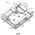
図2A〜2Cは幾つかの例示的実施形態による、センサシステム及び電動式紐締め動力源(エンジン)を大まかに示す。図2Aは例示的紐締め動力源110における外部的な種々の特徴を示し、これら外部的特徴としては、ハウジング構体150、ケースねじ108、紐チャンネル112(紐ガイドレリーフ112とも称する)、紐チャンネル移行部114、スプール窪み115、ボタン開口122、ボタン121、ボタン薄膜シール124、プログラム可能なヘッダー128、スプール131、及びスプール131における紐溝132がある。他の設計も同様に使用することができる。例えば、封止ドーム型スイッチのような他のスイッチタイプを使用することができ、又は薄膜シール124を排除することができる。或る実施例において、紐締め動力源110は、紐締め動力源110の内部回路を紐締め動力源110の外部回路とのインタフェースをとる1つ又はそれ以上の相互接続部又は電気接点を有することができ、外部回路としては、例えば、外部足存在センサ(若しくはそのコンポーネント)、外部アクチュエータのようなスイッチ若しくはボタン、又は他のデバイス若しくはコンポーネントがある。
2A-2C show roughly the sensor system and the electric lacing power source (engine) according to some exemplary embodiments. FIG. 2A shows various external features of the exemplary
紐締め動力源110は、ケースねじ108のような1つ又はそれ以上のねじによってともに保持することができる。ケースねじ108は一次駆動機構近傍に位置決めして、紐締め動力源110の構造的一体性を高めることができる。ケースねじ108は、さらに、外部継ぎ目の超音波溶接するためにハウジング構体150を互いに保持するような組立てプロセスを支援する機能を果たす。
The strapping
図2Aの実施例において、紐締め動力源110は、この動力源を自動履物プラットフォーム内に組み付けた後に紐又は紐ケーブルを収容する紐チャンネル112を有する。紐チャンネル112は、紐ケーブルが操作中に移動できる滑らかなガイド表面を生ずるよう、面取り端縁付きのチャンネル壁を有することができる。紐チャンネル112の滑らかなガイド表面における部分はチャンネル移行部114を有することができ、このチャンネル移行部114は、スプール窪み115に至る紐チャンネル112の拡幅部分とすることができる。スプール窪み115は、チャンネル移行部114からスプール131の輪郭に密に合致するほぼ円形断面に遷移する。スプール窪み115は、巻き付いた紐ケーブルを保持するとともに、スプール131の位置を保持することを支援することができる。他の態様の設計はスプール131を保持する他の手段を提供する。図2Aの実施例において、スプール131は、平坦頂面及びスプールシャフト(図2Aには示さない)を経て反対側の側面から下方に走る紐溝132を有するヨーヨー半部に類似する形状を有する。
In the embodiment of FIG. 2A, the lacing
紐締め動力源110の片側の側面はボタン開口122を有し、このボタン開口122は、自動履物プラットフォームにおける1つ又はそれ以上の形体部を作動又は調整するよう構成し得るボタン121を収容する。ボタン121は、紐締め動力源110内に設けた種々のスイッチを作動させるための外部インタフェースを提供することができる。幾つかの実施例において、ハウジング構体150は、ほこり及び水分から保護するボタン薄膜シール124を有する。この実施例において、ボタン薄膜シール124は、数ミル(数1/1000インチ)までの厚さの透明なプラスチック(又は類似材料)であり、ハウジング構体150の上面から、例えば、コーナーに掛け渡り片側側面に下るよう粘着することができる。他の実施例において、ボタン薄膜シール124は、ボタン121及びボタン開口122を被覆する約2ミル厚さの粘着剤裏打ちビニル薄膜である。他タイプのボタン及びシール材も同様に使用することができる。
One side of the lace-up
図2Bは、頂部セクション102及び底部セクション104を含むハウジング構体150を示す。この実施例において、頂部セクションは、ケースねじ108、紐チャンネル移行部114、スプール窪み115、ボタン開口122、及びボタンシール窪み126のような形体部を有する。或る実施例において、ボタンシール窪み126は、ボタン薄膜シール124の嵌め込み部をなすようレリーフした頂部セクション102の部分である。
FIG. 2B shows the
図2Bの実施例において、底部セクション104は、無線充電器アクセス部105、接合部106、及びグリース隔壁109のような形体部を有する。さらに、特に参照符号で識別されないが、ケースねじ108を収容するケースねじベース、並びに駆動機構の部分を保持するグリース隔壁109内の種々の形体部を示す。グリース隔壁109は、駆動機構を包囲するグリース又は同様の化合物を保持して、紐締め動力源110の種々の電気的コンポーネントから隔絶するよう設計する。
In the embodiment of FIG. 2B, the
ハウジング構体150は、頂部セクション102及び底部セクション104のうち一方又は双方で構体表面内に埋設した又は構体表面上に付着した1つ又はそれ以上の電極170を有することができる。図2Bの実施例における電極170は、底部セクション104に結合したものとして示す。或る実施例において、電極170は、キャパシタンスをベースとする足存在センサ回路(例えば、以下に詳述する足存在センサ310)の一部分を有する。付加的又は代案的に、電極170は、頂部セクション102に結合することができる。頂部セクション102又は底部セクション104に結合した電極は、無線電力送給のために及び/又はキャパシタンスベースの足存在センサ回路の一部分として使用することができる。或る実施例において、電極170はハウジング構体150の外面に配置される1つ又はそれ以上の部分を有することができ、また他の実施例において、電極170は、ハウジング構体150の内面に配置される1つ又はそれ以上の部分を有する。
The
図2Cは、幾つかの例示的実施形態による、電動式紐締め動力源の様々な内部コンポーネントの説明図である。この実施例において、紐締め動力源110は、さらに、スプール磁石136、Oリングシール138、ウォーム駆動部140、ブッシュ141、ウォーム駆動キー、ギアボックス148、ギアモータ145、モータエンコーダ146、モータ回路板147、ウォームギア151、回路板160、モータヘッダー161、バッテリー接続部162、及び有線充電ヘッダー163を有する。スプール磁石136は、磁力計(図2Cには示さない)による検出でスプール131の追跡運動を支援する。Oリングシール138はスプールシャフト周りから紐締め動力源110内に侵入し得るほこり及び水分を封止するよう機能する。回路板160は、以下に説明する容量足存在センサ310のような足存在センサ用の1つ又はそれ以上のインタフェース又は相互接続部を有することができる。或る実施例において、回路板160は、足存在センサ310の一部分をなす1つ又はそれ以上の配線又は導電面を有する。
FIG. 2C is an explanatory view of various internal components of an electric lacing power source, according to some exemplary embodiments. In this embodiment, the string tightening
この実施例において、紐締め動力源110の主な駆動コンポーネントとしては、ウォーム駆動部140、ウォームギア151、ギアモータ145、及びギアボックス148がある。ウォームギア151は、ウォーム駆動部140及びギアモータ145の逆駆動(バックドライブ)を抑止するよう設計し、この逆駆動は、スプール131を介して紐ケーブルから入力される大きな力が比較的大きなウォームギア及びウォーム駆動部の歯を分離させ得ることを意味する。この構成は、履物プラットフォームの運動使用からくる動力学的負荷又は紐締めシステムを締め込むことからくる締め付け負荷の双方に耐える十分なギア強度を持たせる必要性がないように、ギアボックス148を保護する。ウォーム駆動部140は、ウォーム駆動キーのような駆動システムの様々な脆弱部分を保護するよう支援する付加的形体部を有する。この実施例において、ウォーム駆動キーは、ギアボックス148から突出する駆動シャフトに貫通するピンと調和する、ウォーム駆動部140のモータ側端部における半径方向溝孔である。この構成は、ウォーム駆動部140がギアボックス148又はギアモータ145に対する過度の軸方向力を与えるのを防止し、この防止は、ウォーム駆動部140が軸方向に(ギアボックス148から離れる方向に)自由に移動し、これら軸方向荷重をブッシュ141及びハウジング構体150に伝達できるようにすることによって行う。
In this embodiment, the main drive components of the string tightening
図3は、例示的実施形態による、電動式紐締めシステム300のコンポーネントのブロック図を大まかに示す。このシステム300は、電動式紐締めシステムの幾つかのコンポーネントを有し、必ずしもすべてではないが、例えば、インタフェースボタン301、容量性足存在センサ310、及びハウジング構体150を有し、このハウジング構体150は、プロセッサ回路を有する印刷回路板アセンブリ(PCA)320、バッテリー321、充電コイル322、エンコーダ325、モーションセンサ324、及び駆動機構340を包囲する。駆動機構340は、とりわけモータ341、変速装置342、及び紐スプール343を有することができる。モーションセンサ324としては、とりわけ単軸又は多軸の加速度計、磁力計、ジャイロメーター、ハウジング構体150内部若しくはこのハウジング構体150に結合した1つ若しくはそれ以上のコンポーネントの動きを感知するよう構成された他のセンサ若しくはデバイスがあり得る。
FIG. 3 roughly shows a block diagram of the components of the electric strapping
図3の実施例において、プロセッサ回路320は、インタフェースボタン301、足存在センサ310、バッテリー321、充電コイル322、及び駆動機構340とデータ又は電力の信号伝送状態にある。変速装置342は、モータ341をスプール343に連結し、駆動機構340を形成する。図3の実施例において、ボタン301、足存在センサ310及び環境センサ350は、ハウジング構体150の外部又は一部が外部にある状態で示す。
In the embodiment of FIG. 3, the
代替的実施形態において、ボタン301、足存在センサ310、及び環境センサ350のうち1つ又はそれ以上をハウジング構体150内に包囲することができる。或る実施例において、足存在センサ310はハウジング構体150の内部に配置し、発汗及び塵埃又はデブリからセンサを保護する。ハウジング構体150の壁に貫通する接続部を少なくする又は排除することは、アセンブリの耐久性及び信頼性を向上するのに役立てることができる。
In an alternative embodiment, one or more of the
或る実施例において、プロセッサ回路320は、駆動機構340の1つ又はそれ以上の態様を制御する。例えば、プロセッサ回路320は、ボタン310から及び/又は足存在センサ310から及び/又はモーションセンサ324から情報を受信し、これに応じて駆動機構340を制御し、例えば、足の周りに履物を締め付ける又は緩めるよう構成することができる。或る実施例において、プロセッサ回路320は、付加的又は代案的に、足存在センサ310若しくは他の機能用センサからのセンサ情報を取得又は記録するコマンドを発するよう構成する。或る実施例において、プロセッサ回路320は、足存在センサ310を使用して足存在を検出する、足存在センサ310を使用して足の向き若しくは位置を検出する、又はモーションセンサ324を使用して特定しぐさを検出する、のうち1つ又はそれ以上の際に、駆動機構340の動作を調整する。
In certain embodiments, the
或る実施例において、システム300は、環境センサ350を有する。環境センサ350からの情報を使用して、足存在センサ310のベースライン若しくは基準値をアップデート又は調整することができる。以下にさらに説明するように、容量性足存在センサによって測定されるキャパシタンス値は、経時的に、例えば、センサ近傍の周囲条件に応じて変動し得る。環境センサ350からの情報を使用して、プロセッサ回路320及び/又は足存在センサ310は測定した若しくは感知したキャパシタンス値をアップデート若しくは調整するよう構成することができる。
In some embodiments, the
図4は、履物品の着用者が立っているときにおける、履物品400内における公称又は平均的な足の圧力分布データ(左側)及び高い土踏まず(高アーチ)を有する足の圧力分布データ(右側)を示す説明図である。この実施例において、足裏圧力の比較的大きな面積は、ヒール領域401、母趾球(ボール)領域402(例えば、土踏まずとつま先との間)、及び第一趾領域403(例えば、「母趾」領域)に含まれていることが分かる。しかし、上述したように、土踏まず領域又はその近傍のような集中化領域に種々の動的(アクティブ)コンポーネント(例えば、足存在センサ310を含めて)を設けることは有利であり得る。或る実施例において、ハウジング構体150を含む履物品を履くとき、土踏まず領域にあるハウジング構体150は概してユーザーにとって気付かれにくい、又は煩わしくないものであり得る。
FIG. 4 shows nominal or average foot pressure distribution data (left side) and foot pressure distribution data (right side) in the
図4の実施例において、紐締め動力源141を土踏まず(アーチ)領域に設けることができる。足存在センサ310に対応する1つ又はそれ以上の電極は、第1位置405に又はその近傍に位置決めすることができる。第1位置405に位置決めした電極を使用して測定されるキャパシタンス値は、第1位置に対する足の近接度に基づいて異なることができる。例えば、平均的足及び高アーチ足に対してそれぞれ異なるキャパシタンス値が得られ、これはすなわち、足自体の表面が第1位置405から異なる距離に存在するからである。或る実施例において、足存在センサ310及び/又は紐締め動力源110の位置を履物に対して調整して(例えば、ユーザー又は販売時点における技術者によって)、異なるユーザーの異なる足特性に適合させ、また足存在センサ310から取得される信号品質を高めるようにすることができる。或る実施例において、足存在センサ310の感度は、例えば、駆動信号レベルを増加させる、又は足存在センサ310と足との間に位置する誘電性材料を変化させることによって調整することができる。
In the embodiment of FIG. 4, the strapping
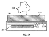
図5A及び5Bは、例示的実施形態による、履物品のインソールにおけるキャパシタンスをベースとする足存在センサの概略図を示す。キャパシタンスをベースとする足存在センサは、センサを組み込んだ物品が着用されるとき、足のような対象物又は身体550の下側に設けることができる。
5A and 5B show a schematic representation of a capacitance-based foot presence sensor in a footwear insole according to an exemplary embodiment. The capacitance-based foot presence sensor can be provided underneath an object such as the foot or
図5Aにおいて、キャパシタンスをベースとする足存在センサは、容量感知型のコントローラ回路502に接続した第1電極アセンブリ501Aを有することができる。或る実施例において、コントローラ回路502は、プロセッサ回路320内に含まれる、又はプロセッサ回路320によって実施される機能を含む。図5Aの実施例において、第1電極アセンブリ501A及び/又はコントローラ回路502は、ハウジング構体150の内側部分内に包含される若しくは取り付けることができる、又はハウジング構体150内部のPCAに接続することができる。或る実施例において、第1電極アセンブリ501Aはハウジング構体150の足に対面する側の表面に配置又は隣接させることができる。或る実施例において、第1電極アセンブリ501Aは、ハウジング構体150の内部上面領域にわたり分布させた複数の配線を有する。
In FIG. 5A, the capacitance-based foot presence sensor can have a
図5Bにおいては、容量感知型のコントローラ回路502に接続した第2電極アセンブリ501Bを有することができる。この第2電極アセンブリ501Bは、ハウジング構体150の外側部分に又はその近傍に取り付けることができ、また例えば、可撓性コネクタ511を用いて、ハウジング構体150の内部におけるPCAに電気的に接続することができる。或る実施例において、第2電極アセンブリ501Bは、ハウジング構体150の足に対面する側の表面に配置又は隣接させることができる。或る実施例において、第2電極アセンブリ501Bは、ハウジング構体150の内面又は外面に固定した可撓性回路を有し、また1つ又はそれ以上の導体を介してプロセッサ回路320に接続する。
In FIG. 5B, a
或る実施例において、コントローラ回路502は、アトメル(Atmel)社製であるATSAML21E18B-MU、STマイクロエレクトロニクス社製であるSTM32L476M、又は他の同様なデバイスを含む。コントローラ回路502は、とりわけ第1又は第2の電極アセンブリ501A又は501Bにおける少なくとも1対の電極対にAC駆動信号を供給し、またそれに応じて、以下により詳細に説明するように、電極対に対する対象物又は身体550の近接度の対応変化に基づく電場変化を感知するよう構成することができる。或る実施例において、コントローラ回路502は、足存在センサ310又はプロセッサ回路320を含む若しくは使用する。
In certain embodiments, the
電極アセンブリ501と感知すべき対象物又は身体550との間に種々の材料を設けることができる。例えば、電極絶縁体、ハウジング構体150の材料、インソール材料、インサート材料510、靴下若しくは他の足カバー、身体テープ、運動生理学テープ、又は他の材料を、身体550と電極アセンブリ501との間に介在させて、履物の誘電特性を変化させ、またこれによって、電極アセンブリ501を含む又は使用するセンサのキャパシタンス検出感度に影響を与えるようにすることができる。コントローラ回路502は、介在する材料の数又はタイプに基づく励起若しくは感知パラメータをアップデート又は調整し、これにより、例えば、電極アセンブリ501を用いて感知されるキャパシタンス値の感度若しくは信号対ノイズ比を向上させるよう構成することができる。
Various materials can be provided between the electrode assembly 501 and the object to be sensed or the
図5A/5Bの実施例において、第1及び/又は第2の電極アセンブリ501A及び/又は501Bは、コントローラ回路502内の信号ジェネレータによって励起することができ、またこの結果として、電極アセンブリ頂部の足に対面する側面から電場を放出することができる。或る実施例において、電極アセンブリ下側の電場は、感知電極下側に位置決めされる被駆動シールドを使用して少なくとも部分的にブロックすることができる。この被駆動シールド及び電極アセンブリは、互いに電気的に絶縁することができる。例えば、第1電極アセンブリ501AがPCAの一方の表面上にある場合、被駆動シールドはPCAの底部層に、又は多層PCAにおける複数内側層のうち任意な1つの層に配置することができる。或る実施例において、被駆動シールドは、第1電極アセンブリ501Aの表面積に等しい又はそれより大きいものとすることができ、また第1電極アセンブリ501Aの直ぐ下側で中心合わせすることができる。
In the embodiment of FIG. 5A / 5B, the first and / or
被駆動シールドは駆動信号を受信することができ、またこれに応じて電場を発生することができる。被駆動シールドが発生する電場は、第1電極アセンブリ501Aが発生する電場と極性、位相及び/又は大きさがほぼ同一のものとすることができる。被駆動シールドの電場は、第1電極アセンブリ501Aの電場に反発することができ、これにより、PCAの接地平面に対する望ましくない結合のような種々の寄生効果からセンサ場を絶縁することができる。被駆動シールドが発生する電場は、特定エリアに対する直接及び合焦検出に役立てることができ、環境効果を軽減するのに役立てることができ、また寄生キャパシタンス効果を軽減するのに役立てることができる。或る実施例において、被駆動シールドを含めることは、センサアセンブリにおける温度変化効果を軽減することができる。温度は寄生オフセット特性に影響を与えることができ、また温度変化は、例えば、寄生接地面キャパシタンスを変化させるおそれがある。センサ電極と接地面との間に挿入されるようなシールドを用いることは、センサ測定結果から寄生接地面キャパシタンスの影響を軽減するのに役立てることができる。
The driven shield can receive a drive signal and can generate an electric field accordingly. The electric field generated by the driven shield can be substantially the same in polarity, phase and / or magnitude as the electric field generated by the
被駆動シールドは、第2電極アセンブリ501Bでの使用にも同様に設けることができる。例えば、第2電極アセンブリ501Bは、図5Bの実施例に示すように、ハウジング構体150の上方に又はそれに隣接して設けることができる。或る実施例において、ハウジング構体150の一部分は、被駆動シールドとして使用される導電性フィルムを含む又はそれによって部分的に被覆することができる。付加的又は代案的に、被駆動シールドは、第2電極アセンブリ501Bをハウジング構体150の頂部又はそれに隣接する部分以外の位置に設けるとき、履物品の他の場所に設けることができる。
The driven shield can be similarly provided for use in the
ハウジング構体150を配置する好適な位置は履物のアーチ面域であり、これはすなわち、着用者が感じにくい面域であり、また不快感を着用者に与えにくいからである。履物内の足を検出する上で容量感知を用いることの1つの利点は、容量センサをアーチ領域に配置し、またユーザーが比較的又は異常に高い土踏まず(アーチ)を有するときでも、容量センサがうまく機能することができる点にある。例えば、センサ駆動信号の大きさ又は形態特性は容量センサから受信される信号の検出した信号対ノイズ比に基づいて変化又は選択することができる。或る実施例において、センサ駆動信号は、履物を使用する度毎にアップデート又は調整することができ、これにより例えば、第1又は第2の電極アセンブリ501A又は501Bと、身体550との間に配置される1つ若しくはそれ以上の材料(例えば、靴下、インソール等々)の変化に対処できる。
A suitable position for arranging the
或る実施例において、容量センサの電極アセンブリ、例えば第1又は第2の電極アセンブリ501A又は501Bは、複数電極間、例えば、X軸配向性電極とY軸配向性電極との間における信号差を感知するよう構成することができる。或る実施例において、好適なサンプリング周波数は、約2〜50Hzの間であり得る。幾つかの実施例において、キャパシタンスをベースとする足存在感知技術は、インソール上又は足周りの靴下内における発汗(湿気)に対して比較的不変であり得る。このような水分の効果は、水分の存在が測定されるキャパシタンスを上昇させるため検出のダイナミックレンジを縮小させ得る。しかし、幾つかの実施例において、そのダイナミックレンジは、履物内の水分が予想レベル内においてこの効果に対処するのに十分である。
In one embodiment, the electrode assembly of the capacitance sensor, eg, the first or
図6は、例示的実施形態による、足存在検出のための容量性センサシステム600を大まかに示す。このシステム600は、身体550(例えば、運動履物品内又はその近傍にある足を示す)と、第1及び第2の電極601及び602を有する。電極601及び602は、図5A/Bの実施例からの第1及び第2の電極アセンブリ501A又は501Bにおけるすべて又は一部分を形成することができ、例えば、足存在センサ310の一部分を有することができる。図6の実施例において、第1及び第2の電極601及び602は、互いにまた身体550に対して垂直方向に離間している状態で示すが、例えば、図7〜9Cの実施例で詳細に説明するように、水平方向に離間させることもできる。すなわち、或る実施例においては、電極を身体550の下面に平行な平面上に配置ことができる。図6の実施例において、第1電極601は、伝送電極として構成し、また信号ジェネレータ610に接続する。或る実施例において、信号ジェネレータ610は図3の実施例からのプロセッサ回路320の一部分を構成する。すなわち、プロセッサ回路320は、駆動信号を発生し、また駆動信号を第1電極601に供給するよう構成することができる。
FIG. 6 roughly shows the
信号ジェネレータ610からの駆動信号で第1電極601を励起する結果として、電場615が主に第1電極601と第2電極602との間で発生することができる。すなわち、発生した電場615における種々の成分は、第1電極601と第2電極602との間に延在し、また発生した電場615における他の周辺成分は他の方向に延在することができる。例えば、周辺成分は、トランスミッタ電極又は第1電極601からハウジング構体150(図6の実施例には示さない)に離間する方向に延在し、レシーバ電極又は第2電極602に終端することができる。
As a result of exciting the
身体550の近接に起因する電場615の変化についての情報を含めて、電場615についての情報は第2電極602によって感知又は受信することができる。第2電極602から感知された信号は種々の回路を用いて処理することができ、また身体550の存在又は不在を示すアナログ又はデジタルの信号を供給するのに使用することができる。
Information about the
例えば、電場615の電場強度は、第2電極602によって受信され、またキャパシタンス表示アナログ信号をデジタル信号に変換するよう構成されるΣ-Δアナログ・ツー・デジタル変換器回路(ADC)620を用いて測定される。電極近傍の電気的環境は、身体550のような対象物が周辺成分を含む電場615に侵入するとき、変化する。身体550が電場に進入するとき、電場615の一部分が第2電極602に受信かつ終端される代わりに、接地側に分流される又は電極602に受信される前に身体550を通過する(空中通過の代わりに)。この結果として、足存在センサ310及び/又はプロセッサ回路320によって検出できるキャパシタンス変化を生じ得る。
For example, the electric field strength of the
或る実施例において、第2電極602はほぼ連続的に電場情報を受信し、またこの情報はADC620によって連続的又は周期的にサンプリングすることができる。ADC620からの情報はオフセット量621に従って処理又はアップデートされ、また次にデジタル出力信号を供給することができる。或る実施例において、オフセット量621はキャパシタンスオフセット量であり、特定又はプログラムすることができる(例えば、プロセッサ回路320内部で)、又は経時的環境変化、温度、及び環境の他の可変特性を追跡するのに使用される他のキャパシタに基づくものとすることができる。
In some embodiments, the
或る実施例において、デジタル出力信号622は、例えば、測定したキャパシタンス値を特定閾値と比較することによって、身体550の決定した存在又は不在についての2値情報を含むことができる。或る実施例において、デジタル出力信号622は、測定したキャパシタンスについての定性的情報を含み、この情報を用いて(例えば、プロセッサ回路320が)、身体550の存在又は不在の可能性を表示することができる。
In certain embodiments, the
周期的に、又は足存在センサ310がアクティブでない場合にはいつでも(例えば、モーションセンサ324からの情報を用いて決定されるような)、キャパシタンス値を測定し、また基準値、ベースライン値、又は周囲値として保存することができる。足又は身体が足存在センサ310並びに第1及び第2の電極601及び602に接近するとき、測定されるキャパシタンスは、例えば、保存した基準値に対して増減し得る。或る実施例において、1つ又はそれ以上の閾値キャパシタンスレベルを、例えば、プロセッサ回路320を有するオンチップレジスタに保存することができる。測定したキャパシタンス値が特定閾値を超えるとき、身体550は、足存在センサ310を収納する履物に対しての存在(又は不在)を決定することができる。
Periodically or whenever the
足存在センサ310、並びに足存在センサ310の一部分を構成する電極601及び602は、以下の幾つかの非限定的実施例で示すように、複数の異なる形態をとることができる。或る実施例において、足存在センサ310は、複数電極又はプレート間における相互キャパシタンスについての情報を感知又は使用するよう構成する。
The
或る実施例において、電極601及び602は、電極グリッドとして配列する。このグリッドを用いる容量センサは、グリッドにおける各行及び各列の各交点に可変キャパシタを有することができる。随意的に、この電極グリッドは、1つ若しくは複数の行又は列に配列した電極を有する。電圧信号を行又は列に印加することができ、またセンサ表面近傍における身体又は足は、局所的電場に影響を及ぼすことができ、またこのことは、相互キャパシタンス効果を軽減することができる。或る実施例において、グリッドにおける複数ポイントでのキャパシタンス変化を測定して身体位置を決定することができ、この測定は各軸における電圧を測定することによって行う。或る実施例において、相互キャパシタンス測定技術は、グリッド周りの複数位置からの情報を同時に供給することができる。
In some embodiments, the
或る実施例において、相互キャパシタンス測定は送信電極及び受信電極の直交グリッドを使用する。このようなグリッドをベースとするセンサシステムにおいて、測定結果は複数のX-Y座標対の各々に対して検出され得る。或る実施例において、多重キャパシタからのキャパシタンス情報を使用して、履物内における足の存在又は足の向きを決定することができる。他の実施例において、1つ又はそれ以上のキャパシタからのキャパシタンス情報は経時的に取得かつ解析して、足の存在又は足の向きを決定することができる。或る実施例において、X及び/又はY検出座標についての変化率情報を使用して、足が履物内のインソールに対して適正又は完全に着座する時点又は着座するか否かを決定することができる。 In some embodiments, mutual capacitance measurements use orthogonal grids of transmit and receive electrodes. In such a grid-based sensor system, measurement results can be detected for each of a plurality of XY coordinate pairs. In certain embodiments, capacitance information from multiple capacitors can be used to determine the presence or orientation of the foot in the footwear. In other embodiments, capacitance information from one or more capacitors can be acquired and analyzed over time to determine the presence or orientation of the foot. In certain embodiments, rate of change information about the X and / or Y detection coordinates may be used to determine when or whether the foot is properly or completely seated on the insole in the footwear. it can.
或る実施例において、自己キャパシタンスベースの足存在センサは相互キャパシタンスセンサとして同一のX-Yグリッドを有することができるが、列及び行は独立的に動作することができる。自己キャパシタンスセンサにおいて、各列又は行における身体の容量性負荷は独立的に検出することができる。 In some embodiments, the self-capacitance-based foot presence sensor can have the same XY grid as mutual capacitance sensors, but the columns and rows can operate independently. In the self-capacitance sensor, the capacitive load of the body in each column or row can be detected independently.
図7は、例示的実施形態による、第1キャパシタンスベース足存在センサの概略図を大まかに示す。図7の実施例において、第1容量センサ700は、複数の平行容量プレートを有する。複数プレートは、例えば、第1容量センサ700を有する履物品が履かれるときの足裏面に又はその近傍に位置決めされるハウジング構体150上又は内部に配列することができる。或る実施例において、容量足存在センサ310は第1容量センサ700を含む又は使用する。
FIG. 7 roughly shows a schematic view of the first capacitance-based foot presence sensor according to an exemplary embodiment. In the embodiment of FIG. 7, the
図7の実施例において、4つのキャパシタンスプレートを参照符号701〜704として示す。プレートは導電性フォイルのような導電性材料で形成することができる。このフォイルは、可撓性とすることができ、また随意的にハウジング構体150のプラスチック内に埋設することができる。フィルム、インク、溶着金属のような任意な導電性材料を使用できると理解されたい。図7の実施例において、プレート701〜704は、共通平面内に配列され、また離散導電性素子又は電極を形成するよう互いに離して配置する。
In the embodiment of FIG. 7, four capacitance plates are shown as
キャパシタのキャパシタンス値は、キャパシタを形成する2つのプレート間における材料の誘電率に関数的に関連する。第1容量センサ700内で2つ又はそれ以上のキャパシタプレート701〜704における各対間にキャパシタを形成することができる。したがって、図7でキャパシタA、B、C、D、E、及びFとして示される6個の実効キャパシタは、キャパシタプレート701〜704の6個の固有組合せ対によって形成することができる。随意的に、2つ又はそれ以上のプレートは単一プレートを形成するよう電気的に接続することができる。すなわち、或る実施例において、キャパシタは、第1導体を得るよう、互いに電気的に接続した第1及び第2のキャパシタプレート701及び702を用いて形成することができ、また第2導体を得るよう、互いに電気的に接続した第3及び第4のキャパシタプレート703及び704を用いて形成することができる。
The capacitance value of a capacitor is functionally related to the permittivity of the material between the two plates forming the capacitor. Capacitors can be formed between each pair of two or more capacitor plates 701-704 within the
或る実施例において、第1キャパシタ701と第2キャパシタ702との間における容量効果は、図7に文字Aで示す仮想キャパシタによって表される。第1キャパシタ701と第3キャパシタ703との間における容量効果は、図7に文字Bで示す仮想キャパシタによって表される。第2キャパシタ702と第4キャパシタ704との間における容量効果は、図7に文字Cで示す仮想キャパシタによって表される。当業者であれば、各幻想キャパシタは、キャパシタプレートの対応対間に延在する電場を表すことは理解されるであろう。以下には、分かり易い表示目的のため、容量プレートの各対によって形成されるキャパシタは、図7で使用される文字(例えば、「A」、「B」等々)で参照され、仮想キャパシタを識別する。
In some embodiments, the capacitive effect between the
図7の実施例におけるキャパシタプレートの各対に対して、プレート間の実効誘電体はプレート間に配置される空隙(又は他の材料)を有する。キャパシタプレートの各対に対して、容量プレートの対応の対に近接する身体又は足の何らかの部分は、或る容量プレート対における実効誘電体の一部となり得る又は実効誘電体に影響を与え得る。すなわち、対応するプレート対に対する身体の近接度に従って、各キャパシタプレート対間に可変誘電体を生ずることができる。例えば、或るプレート対に対して身体又は足が接近すればするほど、誘電体の実効値が大きくなる。誘電率の値が増加するにつれて、キャパシタンス値が増加する。このようなキャパシタンス値変化は、プロセッサ回路320が受信することができ、またこれを使用して身体が第1容量センサ700に存在する又はその近傍に存在するか否かを示すことができる。
For each pair of capacitor plates in the embodiment of FIG. 7, the effective dielectric between the plates has voids (or other material) placed between the plates. For each pair of capacitor plates, any part of the body or foot in close proximity to the corresponding pair of capacitance plates can be part of or affect the effective dielectric in a pair of capacitance plates. That is, variable dielectrics can be created between each capacitor plate pair according to the proximity of the body to the corresponding plate pair. For example, the closer the body or foot is to a pair of plates, the greater the effective value of the dielectric. As the value of permittivity increases, the value of capacitance increases. Such a change in capacitance value can be received by the
容量センサ700を含む足存在センサ310の実施例において、複数の容量センサ駆動/モニタ回路をプレート701〜704に接続することができる。例えば、別個の駆動/モニタ回路を図7の実施例におけるキャパシタプレート対に関連付けることができる。或る実施例において、駆動/モニタ回路は駆動信号(例えば、経時変動電気励起信号)をキャパシタプレート対に供給することができ、またこれに応じてキャパシタンス表示値を受信することができる。各駆動/モニタ回路は、関連するキャパシタ(例えば、第1及び第2のプレート701及び702に対応するキャパシタ「A」)の可変キャパシタンスを測定するよう構成することができ、またさらに、測定したキャパシタンス値を示す信号を供給するよう構成することができる。駆動/モニタ回路は、キャパシタンスを測定するための任意の適当な構体を有することができる。或る実施例において、2つ又はそれ以上の駆動/モニタ回路を一緒に使用して、例えば、異なるキャパシタを用いて測定したキャパシタンス値間における差の表示を生ずるようにすることができる。
In the embodiment of the
図8は、例示的実施形態による、第2キャパシタンスベース足存在センサの概略図を大まかに示す。図8の実施例は、第1及び第2の電極801及び802を含む第2容量センサ800を備える。足存在センサ310は、第2容量センサ800を含む又は使用することができる。図8の実施例において、第1及び第2の電極801及び802は、ほぼ平面状の表面に沿ってくし形の形態に配列する。或る実施例において、プロセッサ回路320のような駆動回路は、第1及び第2の電極801及び802に印加する励起又は刺激信号を発生するよう構成することができる。同一又は異なる回路は、第1及び第2の電極801及び802間におけるキャパシタンス変化を表している応答信号を感知するよう構成することができる。キャパシタンスは、電極に対する身体又は足の存在によって影響を受けることができる。例えば、第1及び第2の電極801及び802は、例えば、ハウジング構体150を含む履物内に足が存在するとき足に隣接するような、ハウジング構体150の表面上又はその近傍に配列することができる。
FIG. 8 roughly shows a schematic view of the second capacitance-based foot presence sensor according to an exemplary embodiment. The embodiment of FIG. 8 comprises a
或る実施例において、第2容量センサ800は、電極パターンを形成するようX-Yグリッドのようなエッチングした導電層を有する。付加的又は代案的に、第2容量センサ800の電極は、導電性材料における複数の互いに分離しかつ平行な層をエッチングする、例えば、グリッドを形成するよう互いに直交するライン又はトラックを設けるようエッチングすることによって得ることができる。この及び他の容量センサにおいて、身体又は足と導電層又は電極との間における直接接触は必要としない。例えば、導電層又は電極は、ハウジング構体150内に埋設することができる、又は保護若しくは絶縁層でコーティングすることができる。その代わり、検出すべき身体又は足は、電極近傍の電場特性に干渉又は影響を与えることができ、また電場変化を検出することができる。
In some embodiments, the
或る実施例において、別個のキャパシタンス値が、接地又は基準に対する第1電極801に対して、及び接地又は基準に対する第2電極802に対して測定され得る。足存在検出に使用される信号は、第1及び第2の電極801及び802に対して測定される別個のキャパシタンス値間における差に基づくものであり得る。すなわち、足存在又は足検出の信号は、第1及び第2の電極801及び802を使用して測定される個別キャパシタンス信号間の差に基づくものであり得る。
In certain embodiments, separate capacitance values can be measured for the
図9A及び9Bは、幾つかの実施例による第3容量センサ900の例を大まかに示す。図9Cは、第4容量センサ902の例を大まかに示す。図9Aは第3容量センサ900の概略的平面図を示す。図9Bは、第3容量センサ900を含むセンサアセンブリ901の分解斜視図を示す。図9Cは、第4容量センサ902の概略的平面図を示す。
9A and 9B show roughly an example of the
図9Aの実施例において、第3容量センサ900は、第1電極配線911及び第2電極配線912を有する電極領域を含む。第1及び第2の電極配線911及び912は、絶縁体配線913によって分離する。或る実施例において、第1及び第2の電極配線911及び912は、導電性材料のうちとりわけ銅、炭素、銀とすることができ、また材料のうちとりわけFR4、ポリイミド、PETから作製した基板上に配置することができる。第3容量センサ900の基板及び配線は、1つ又はそれ以上の可撓性部分を含むことができる。
In the embodiment of FIG. 9A, the
第1及び第2の電極配線911及び912は、第3容量センサ900の基板における表面積にわたりほぼ分布させることができる。電極配線は、第3容量センサ900を設置するときハウジング構体150の上面又は頂面に当接するよう位置決めすることができる。或る実施例において、第1及び第2の電極配線911及び912のうち一方又は双方は、約2mmの幅を有することができる。絶縁体配線913はほぼ同一幅とすることができる。或る実施例において、配線幅は、とりわけ、履物サイズ又はインソールタイプに基づいて選択することができる。例えば、配線と感知すべき身体との間の距離、インソール材料、ギャップ充填材、ハウジング構体150の材料、又は履物に使用される他の材料に基づいて、例えば、第3容量センサ900を用いて測定されるキャパシタンス値の信号対ノイズ比を最大化するよう、異なる配線幅を、第1及び第2の電極配線911及び912に対して及び/又は絶縁体配線913に対して選択することができる。
The first and
第3容量センサ900は、コネクタ915を有することができる。このコネクタ915は、ハウジング構体150におけるPCAに接続されるような整合コネクタに接続することができる。整合コネクタは、第1及び第2の電極配線911及び912をプロセッサ回路320に電気的に接続する1つ又はそれ以上の導体を有することができる。
The
或る実施例において、第3容量センサ900は入力信号導体920A及び920Bを有する。入力信号導体920A及び920Bは、1つ又はそれ以上の入力デバイス、例えば、ドームボタン又は図2Aの実施例におけるボタン121に対応するような他のスイッチに接続するよう構成することができる。
In some embodiments, the
図9Bは第3容量センサ900、ボタン121A及び121B、並びに薄膜シール124A及び124Bを含むセンサアセンブリ901を示す。或る実施例において、入力信号導体920A及び920Bにおける対応の導電性表面はボタン121A及び121Bに結合する。薄膜シール124A及び124Bはボタン121A及び121B上に付着し、例えばボタン121A及び121Bをデブリから保護し、また導体表面との整列状態を保持する。
FIG. 9B shows a
図9Cの実施例において、第4容量センサ902は第1電極配線921及び第2電極配線922を有する電極領域を含む。第1及び第2の電極配線921及び922は、絶縁体配線923によって分離する。電極配線は種々の導電性材料を有することができ、また第4容量センサ902は1つ又はそれ以上の可撓性部分を有することができる。第4容量センサ902はコネクタ925を有することができ、またハウジング構体150のPCAに接続されるような整合コネクタに接続することができる。
In the embodiment of FIG. 9C, the
本発明者らは、解決すべき問題には、例えば、足存在センサのすべて又は一部が検出すべき足又は身体から空隙又は他の介在材料によって離れているとき、容量性足存在センサからの適正な感度又は応答性を確立することにあると認識した。本発明者らは、解決法としては、特定の形状、サイズ、及び配向性の複数の電極を用いて、電極が付勢されるときに生ずる電場の配向性及び相対強度を高めることを含むと認識した。すなわち、本発明者らは、容量性足存在感知に使用するための最適電極形態を特定した。 The problem to be solved is, for example, from the capacitive foot presence sensor when all or part of the foot presence sensor is separated from the foot or body to be detected by a gap or other intervening material. Recognized that it is to establish appropriate sensitivity or responsiveness. The inventors include using a plurality of electrodes of a particular shape, size, and orientation to increase the orientation and relative strength of the electric field that occurs when the electrodes are urged. I recognized. That is, the present inventors have specified the optimum electrode morphology for use in capacitive foot presence detection.
或る実施例において、第4容量センサ902の複数電極は第1及び第2の電極配線921及び922を有し、この第1及び第2の電極配線921及び922の各々が互いにほぼ平行に延在する複数の離散フィンガ又は配線部を有する。例えば、第1及び第2の電極配線921及び922は、図9Cに示すような、複数の交互配置される導電性フィンガを有することができる。
In some embodiments, the plurality of electrodes of the
或る実施例において、第2電極配線922は、第4容量センサ902の外周端縁又は表面部分に沿ってほぼ存在する汀線(ショアライン)又は周縁部分を有することができ、また第1電極配線921の周りをほぼ包囲する。図9Cの実施例において、第2電極配線922を含む汀線は第4容量センサ902の頂面のほぼ全体に沿って延在するが、幾つかの他の実施例においてはセンサのより少ない部分に沿って延在することができる。本発明者らは、さらに、非平行は1つ又はそれ以上の配線又はフィンガ部分を含む代わりに、第1及び第2の電極配線921及び922におけるフィンガの大部分又はすべてが互いにほぼ平行に配列されているとき、足存在を検出する最適電場を生ずることを認識した。例えば、第4容量センサ902とは対比的に、図9Aの第3容量センサ900は、例えば、垂直方向に延在するフィンガ部分を含む第1電極配線911の上方部分及び水平方向に延在するフィンガ部分を含む第1電極配線911の下方部分におけるように、非平行フィンガを含む。第1及び第2の電極配線921及び922の相対厚さは、センサの感度をより高めるよう調整することができる。或る実施例において、第2電極配線922は第1電極配線921よりも3倍又はそれ以上の倍数分だけ厚くする。
In some embodiments, the
或る実施例において、第1、第2、第3、及び第4の容量センサ700、800、900、及び902のうち1つ又はそれ以上を用いるような足存在センサ310によって測定されるキャパシタンス値は、図3のプロセッサ回路320のようなコントローラ又はプロセッサ回路に供給することができる。測定したキャパシタンスに応じて、プロセッサ回路320は駆動機構340を作動させ、例えば、足周りの履物張力を調整できるようにする。この調整動作は、随意的にソフトウェアを実行するプロセッサによって実施できる、又は有線コンポーネント及びソフトウェアの組合せで実施できる、別個の「有線」コンポーネントによって少なくとも部分的に実施することができる。或る実施例において、駆動機構340の作動には、(1) プロセッサ回路320を使用するような、1つ又はそれ以上の駆動/モニタリング回路を使用する足存在センサ310からの信号をモニタリングすること、(2) もしある場合には受信したうちどのキャパシタンス信号が特定閾値(例えば、プロセッサ回路320の記憶レジスタ内及び/又はプロセッサ回路320にデータ通信するメモリ回路に保存される)に合致又は超えるキャパシタンス値を示すか否かを決定すること、(3) 例えば、種々の特定閾値が超えられることに基づいて、足存在センサ310近傍における身体又は足の位置、サイズ、向き又は他の特徴を特徴付けすること、及び(4) 該特徴付けに基づいて駆動機構340の作動を許可、有効化、調整、又は抑止すること、が含まれる。
Capacitance values measured by a
図10は、履物センサからの足存在情報を使用するステップを含む方法1000の実施例を示すフローチャートを図解する。動作ステップ1010において、この実施例は、足存在センサ310からの足存在情報を受信する。足存在情報は、足が履物内に存在するか否かについての2値情報(例えば、図12〜14の実施例で詳述する割込み信号参照)を含むことができる、又は足が履物品内に存在する可能性表示を含むことができる。情報は、足存在センサ310からプロセッサ回路320への電気信号を含むことができる。或る実施例において、足存在情報は、履物内における1つ又はそれ以上のセンサに対する足の位置についての定性的情報を含む。
FIG. 10 illustrates a flowchart illustrating an embodiment of
動作ステップ1020において、実施例は足が履物内に完全に着座したか否かを決定する。足が完全に着座したことをセンサ信号が示す場合、実施例は、動作ステップ1030に継続して、駆動機構340を作動させることができる。例えば、動作ステップ1020で足が完全に着座することを決定するとき、上述したように、足存在センサ310からの情報に基づいて、駆動機構340がスプール131を介して履物紐を締め込むことに従事することができる。足が完全に着座しないことをセンサ信号が示す場合、実施例は、動作ステップ1022に継続して、幾分の特定インターバル(例えば、1〜2秒又はそれ以上)にわたり遅延又は空転させることによってことができる。特定遅延の経過後、実施例は、動作ステップ1010に戻り、またプロセッサ回路が足存在センサ310からの情報を再び採取して、足が完全に着座したか否かを決定することができる。
In
動作ステップ1030において駆動機構340が作動した後、プロセッサ回路320は動作ステップ1040で足位置情報をモニタリングするよう構成することができる。例えば、プロセッサ回路は、履物内の足の絶対又は相対位置についての足存在センサ310からの情報を、周期的又は間欠的にモニタリングするよう構成することができる。或る実施例において、動作ステップ1040での足位置情報モニタリング及び動作ステップ1010での足存在情報受信は、同一又は異なる足存在センサ310からの情報を受信するステップを含むことができる。例えば、異なる電極を使用して、動作ステップ1010及び1040における足存在又は足位置の情報をモニタリングすることができる。
After the
動作ステップ1040において、実施例は、ボタン121のような履物に関連する1つ又はそれ以上のボタンからの情報をモニタリングするステップを含む。ボタン121からの情報に基づいて、駆動機構340は、ユーザーが履物を脱ぐことを希望するときのように、紐を離脱又は緩めるよう命令を受けることができる。
In
或る実施例において、駆動機構340を作動させる又は紐を締め込むためのフィードバック情報として、紐張力情報を、付加的又は代案的にモニタリング又は使用することができる。例えば、紐張力情報は、モータ341に印加される駆動電流を測定することによってモニタリングすることができる。この張力は、製造時点で特徴付けする、又はユーザーがプリセット若しくは調整することができる、及びモニタリング又は測定される駆動電流レベルに相関付けることができる。
In certain embodiments, the string tension information can be additionally or optionally monitored or used as feedback information for activating the
動作ステップ1050において、実施例は履物内で足位置が変化するか否かを決定する。足存在センサ310及びプロセッサ回路320によって足位置の変化がないことが検出される場合、動作ステップ1052に継続して遅延を行うことができる。動作ステップ1052における特定遅延インターバル経過後、足存在センサ310からの情報を再採取する動作ステップ1040に戻り、再度足位置が変化したか否かを決定することができる。動作ステップ1052における遅延は、約1ミリ秒から数秒にわたる範囲内とすることができ、また随意的にユーザーが特定することができる。
In
或る実施例において、動作ステップ1052における遅延は、例えば、履物使用特徴を決定することに応答して、プロセッサ回路320が自動的に決定することができる。例えば、着用者が激しい運動に従事していること(例えば、ランニング又はジャンピング)をプロセッサ回路320が決定する場合、プロセッサ回路320は、動作ステップ1052で得られる遅延持続時間を減少させることができる。着用者が激しい運動に従事していないこと(例えば、歩行又は着席)をプロセッサ回路が決定する場合、プロセッサ回路320は、動作ステップ1052で得られる遅延持続時間を増加させることができる。遅延持続時間を増加させることによって、プロセッサ回路320による及び/又は足存在センサ310によるセンササンプリングイベント及びこれに対応する電力消費を先送りしてバッテリー寿命を確保することができる。或る実施例において、動作ステップ1050で位置変化が検出される場合、実施例は、動作ステップ1030に戻り、例えば、足周りに履物を締め込む又は緩めるよう駆動機構340を作動させることができる。或る実施例において、プロセッサ回路320は、駆動機構340用に履歴コントローラを設ける又は組み込み、例えば、足位置に僅かな変化しか検出されないイベントで、望ましくない紐スプール巻き付けを回避することの補助を行う。
In some embodiments, the delay in
図11は、履物センサからの足存在情報を用いる方法1100の実施例を示すフローチャートを図解する。図11の実施例は、例えば、プロセッサ回路320及び足存在センサ310を使用する実施形態であり得るような状態マシンの動作に言及することができる。
FIG. 11 illustrates a flowchart showing an embodiment of the
状態1110は、運動履物品としての初期設定又はベースライン状態を表す「出荷(Ship)」状態を含むことができ、この履物品は、足存在センサ310からの情報によって影響を受けることがあり得る1つ又はそれ以上の特徴を含む。出荷状態において、履物の種々の能動コンポーネントは、履物のバッテリー寿命を確保するよう、スイッチオフ又は非作動状態にされる。
The
「電源投入(Power Up)」イベント1115に応じ、実施例は、「無効化(Disabled)」又は無作動状態1120に遷移することができる。運動履物の駆動機構340又は他の特徴は、無効状態1120で待機状態に留まることができる。無効化状態1120から脱するトリガイベントとして種々の入力を使用することができる。例えば、1つのボタン121からのユーザー入力を使用して、無効化状態1120からの遷移を表明することができる。或る実施例において、モーションセンサ324からの情報を起動信号として使用することができる。モーションセンサ324からの情報としては、ユーザーが靴を準備位置に配置する、又はユーザーが足を履物内に挿入し始めることに対応するような、履物の運動についての情報を含むことができる。
In response to the "Power Up"
自動紐締め有効化イベント1123に出会う又は受信するまでは、状態マシンは電源投入イベント1115に続く無効化状態1120に留まることができる。自動紐締め有効化イベント1123は、ユーザーが手動でトリガすることができる(例えば、駆動機構340に対するユーザー入力又はインタフェースデバイスを使用して)、又は例えば、モーションセンサ324から受信されるジェスチャー情報に応答して自動的にトリガすることができる。自動紐締め有効化イベント1123に続いて、較正イベント1125を生ずることができる。較正イベント1125は、センサに対する環境効果を考慮するような、足存在センサ310のキャパシタンスに対する基準値又はベースライン値設定を含むことができる。この較正は、足存在センサ310自体から感知される情報に基づいて実施することができる、又は基準情報をプログラムする又は特定することができる。例えば、較正結果が特定レンジ外にある場合、又は環境効果が過剰である場合、較正を延期することができる。
The state machine can remain in the
自動紐締め有効化イベント1123に続いて、状態マシンは「足存在信号待機(Wait for foot presence signal)」状態1130の保持に進むことができる。この状態1130において、状態マシンは足存在センサ310及び/又はモーションセンサ324からの割込み信号を待機することができる。足が存在することを示す、又は足が存在する十分な可能性を示すような割込み信号を受信する際に、イベントレジスタは、イベント1135での「足発見(Foot found)」を示すことができる。
Following the automatic
状態マシンは足発見イベント1135を生じたとき種々の機能に遷移又は開始することができる。例えば、履物は、足発見イベント1135に応答して駆動機構340を用い、張力特徴部を締め込む又は調整するよう構成することができる。或る実施例において、プロセッサ回路320は、駆動機構340を作動させ、足発見イベント1135に応答して初期量だけ紐張力を調整し、またプロセッサ回路320は、他の制御ジェスチャーが検出されない限り若しくは検出されるまでは、又はユーザー入力が受信されない限り若しくは受信されるまではそれ以上の履物締め込みを遅延させる。すなわち、状態マシンは、「行動待機(Wait for move)」状態1140に遷移することができる。或る実施例において、足発見イベント1135に続いて、プロセッサ回路320は駆動機構340を有効化するが、駆動機構を作動させない。状態1140において状態マシンは、付加的に感知される履物モーション情報のために保持又は停止してから、初期張力調整又はその後の張力調整を行う。行動待機状態1140に続いて、足踏み(Stomp)/歩行(Walk)/起立(Stand)イベント1145を検出することができ、またこれに応じて、プロセッサ回路320はさらに履物の張力特徴部を調整することができる。
The state machine can transition or start various functions when the
足踏み/歩行/起立イベント1145は、運動履物内における1つ又はそれ以上のセンサからのような、様々な個別の感知入力を含むことができる。例えば、足踏みイベントは、モーションセンサ324からの情報を含み、この情報は、積極的な加速(例えば、特定又は包括的な方向における)、及び「上向き(up)」又は「直立(upright)」の指向性を示す。或る実施例において、足踏みイベントは、ユーザーが片方の膝をほぼ垂直方向かつ前方に上げる「ハイニー(high knee)」又はキック型イベントを含む。モーションセンサ324からの加速特徴を解析することができ、例えば、加速が特定閾値に合致又は超えるか否かを決定する。例えば、緩慢膝上げイベントは足踏みイベント応答をトリガせず、一方、迅速(rapid)又は急速(quick)膝上げイベントは足踏みイベント応答をトリガする。
The stepping / walking /
歩行(Walk)イベントは積極的足運び(step)パターン及び「上向き」又は「直立」の指向性を示すモーションセンサ324からの情報を含むことができる。或る実施例において、モーションセンサ324及び/又はプロセッサ回路320は足運び(step)イベントを識別するよう構成され、また歩行(Walk)イベントは、いつ足運び(step)イベントが識別されるか、またいつ加速度計(例えば、モーションセンサ324に含める又は別個にする)が履物は直立していることを表示するかで認識することができる。
The Walk event can include information from a
起立イベントは、例えば、モーションセンサからの履物の加速又は向き変化についての更なる情報なしに、「上向き(up)」又は「直立(upright)」の指向性を示すモーションセンサからの情報を含むことができる。或る実施例において、起立イベントは、以下に詳細に説明するように、容量性足存在センサ310からのキャパシタンス信号における変化についての情報を使用して判別することができる。すなわち、足存在センサ310からキャパシタンス信号は、いつユーザーの足が履物に下向き圧力を加えるかのような、ユーザーが起立しているか否かを示すことができる信号変化を含むことができる。
The standing event may include, for example, information from a motion sensor indicating "up" or "upright" directivity without further information about the acceleration or orientation of the footwear from the motion sensor. Can be done. In certain embodiments, the standing event can be determined using information about changes in the capacitance signal from the capacitive
足踏み/歩行/起立イベント1145の特別な実施例は限定的であると考えるべきではなく、また足が足発見イベント1135で検出された後のように、履物の挙動をさらに制御する又は挙動に影響を与えるよう様々な他のジェスチャー、経時的入力、又はユーザー入力の制御を行うことができる。
The special embodiment of the stepping / walking /
足踏み/歩行/起立イベント1145に続き、状態マシンは「紐解き待機(Wait for unlace)」状態1150を含むことができる。紐解き待機状態1150は、履物を弛緩させる、張力解除又は紐解きする命令のためのユーザー入力及び/又はジェスチャー情報(例えば、モーションセンサ324を用いて)をモニタリングすることを含むことができる。この紐解き待機状態1150において、プロセッサ回路320のような状態マネジャーは、紐締め動力源又は駆動機構340が紐解きされ、また足存在信号状態1130に復帰すべきであることを示すことができる。すなわち、第1の例において、紐解きイベント1155が生ずることができ、状態マシンは履物を紐解き状態に遷移することができ、また状態マシンは足存在信号状態1130に復帰することができる。第2の例において、自動紐締め無効化イベント1153を生じて、履物を無効化状態1120に遷移させることができる。
Following the stepping / walking /
図12は、容量性足存在センサからの第1経時変化情報のグラフ1200を大まかに示す。図12の例は、キャパシタンス対時間グラフと、及びこのグラフにプロットしてある第1経時変化キャパシタンス信号1201とを含む。或る実施例においては、第1経時変化キャパシタンス信号1201は、本明細書記載の足存在センサ310を使用して取得することができる。第1経時変化キャパシタンス信号1201は、上述したような足存在センサ310における複数電極との間で測定したキャパシタンス、又は電場における身体の影響表示に対応することができる。或る実施例において、第1経時変化キャパシタンス信号1201は全体又は相対的なキャパシタンス信号値を表し、また他の実施例において、信号は、信号値と基準キャパシタンス信号値との間の差を表す。
FIG. 12 roughly shows a
或る実施例において、第1キャパシタンス信号1201は特定第1閾値キャパシタンス値1211と比較することができる。足存在センサ310は比較を実施するよう構成することができ、又はプロセッサ回路320は、足存在センサ310からのキャパシタンス情報を受信し、また上記比較を実施するよう構成することができる。図12の実施例において、第1閾値キャパシタンス値1211は一定の非ゼロ値であることを示す。第1キャパシタンス信号1201が、時刻T1におけるような第1閾値キャパシタンス値1211に合致又は超えるとき、足存在センサ310及び/又はプロセッサ回路320は第1割込み信号INT1を供給することができる。第1割込み信号INT1は、足存在センサ310によって示されるキャパシタンス値が第1閾値キャパシタンス値1211に合致又は超える限り高いままでいることができる。
In certain embodiments, the
或る実施例において、第1割込み信号INT1は、図10の実施例における、例えば、動作ステップ1010又は1020で使用することができる。動作ステップ1010において、足存在センサ310からの足存在情報を受信することは、プロセッサ回路320におけるような第1割込み信号INT1を受信することを含むことができる。或る実施例において、動作ステップ1020は、足が履物内に完全に着座している又はその可能性が高いか否かを決定する割込み信号情報を使用することを含むことができる。例えば、プロセッサ回路320は、第1閾値キャパシタンス値1211を超えるキャパシタンス値をプロセッサ回路320がどのくらい長く供給するかを決定するための第1割込み信号INT1の持続時間をモニタリングすることができる。この持続時間が特定基準持続時間を超える場合、プロセッサ回路320は足が履物内に完全に着座している又はその可能性が高いか否かを決定することができる。
In some embodiments, the first interrupt signal INT 1 can be used, for example, in
或る実施例において、第1割込み信号INT1は、図11の実施例における、例えば、状態1130又はイベント1135で使用することができる。状態1130において、状態マシンは、プロセッサ回路320から、又は足存在センサ310からINT1のような割込み信号を待機するよう構成することができる。イベント1135において、状態マシンは、第1割込み信号INT1を受信することができ、またこれに応じて1つ又はそれ以上の状態を開始することができる。
In some embodiments, the first interrupt signal INT 1 can be used in, for example,
或る実施例において、第1閾値キャパシタンス値1211は調整可能である。この閾値は、例えば、環境変化に起因するようなときに測定又は検出される変化に基づいてキャパシタンスのベースライン又は基準を変化させることができる。或る実施例において、第1閾値キャパシタンス値1211はユーザーが特定することができる。閾値のユーザー特定が履物の感度に影響を及ぼすことができる。或る実施例において、第1閾値キャパシタンス値1211は、足存在センサ310における又はその周りにおける感知した環境又は材料変化に応じて自動的に調整することができる。
In some embodiments, the first
図13は容量性足存在センサからの第2経時変化情報のグラフ1300を大まかに示す。図13の例は、第1閾値キャパシタンス値1211近傍における第2キャパシタンス信号1202の変動をどのように取り扱い又は使用して、履物内における足の存在又は向きについてのより多くの情報を決定することができるかを示す。
FIG. 13 roughly shows a
或る実施例において、第2キャパシタンス信号1202は足存在センサ310から受信され、また第2キャパシタンス信号1202は第1閾値キャパシタンス値1211と比較する。他の閾値も同様に、とりわけユーザー、履物タイプ、又は環境若しくは環境特性に基づいて使用することができる。図13の例において、第2キャパシタンス信号1202は、時刻T2、T3、及びT4で第1閾値キャパシタンス値1211に交差することができる。或る実施例において、複数の閾値交差を足存在センサ310が使用して、例えば、足が履物に進入するときの足の移動経路を示すことによって、足存在を確実に識別することができる。例えば、時刻T2、T3における第1及び第2の閾値交差によって区切られる時間インターバルは、足のつま先又は指骨が足存在センサ310の電極に又はその近傍に位置決めされる持続時間を示すことができる。感知したキャパシタンスが第1閾値キャパシタンス値1211よりも小さい時刻T3とT4との間におけるインターバルは、足における中足骨の関節又は骨が足存在センサ310の電極上を又はその近傍を移動する時間に対応することができる。中足骨の関節又は骨は、指骨が履物内で移動するとき足存在センサ310に対する指骨の距離よりも大きい距離だけ足存在センサ310から離間することができ、したがって、この結果として測定される時刻T3とT4との間におけるキャパシタンスは小さくなり得る。時刻T4において、足のヒール又は距骨が所定位置内に摺動することができ、土踏まずは足存在センサ310の電極上に着座することができ、これにより感知されるキャパシタンスを再び上昇させ、また第1閾値キャパシタンス値1211を超えることができる。したがって、足存在センサ310又はプロセッサ回路320は、時刻T2とT3との間における第2割込み信号INT2を生じ、また時刻T4後に第3割込み信号INT3を生ずるよう構成することができる。
In some embodiments, the
或る実施例において、プロセッサ回路320は、割込み信号のシーケンスに基づいて足存在を確実に識別するよう構成することができる。例えば、プロセッサ回路320は、受信した割込み信号についての又は受信した割込み信号間における1つ又はそれ以上のインターバルについての情報を使用することができる。例えば、プロセッサ回路は、特定持続時間によって離隔される割込み信号対を探求するよう構成することができる。図13において、例えば、時刻T3とT4との間における持続時間を使用して、例えば、誤差の幾つかの調整可能な又は特定のマージンとともに、足存在の表示を行うことができる。或る実施例において、プロセッサ回路320は、データとして割込み信号を受信し、また例えば、ジェスチャーベースのユーザー入力の一部として他のユーザー入力信号とともにこのデータを処理することができる。或る実施例において、割込み信号の存在又は非存在についての情報を使用して、1つ又はそれ以上の他の信号を有効化又は却下することができる。例えば、割込み信号が受信される又は直近で受信されたとき、加速度計信号はプロセッサ回路320によって有効化及び処理することができる、又は足存在センサに対応する割込み信号が存在しないとき、加速度計信号はプロセッサ回路320により却下することができる。
In certain embodiments, the
図12及び図13の実施例は、足存在センサ310からの測定したキャパシタンス値は環境条件の変化があることを含めて確実に一定又は再現可能である実施例を示す。しかし、多くの履物使用事例において、埋設した電子機器における周囲キャパシタンス変化は、温度、湿度、又は他の環境因子の変化に起因して絶えず又は予測不能に生じ得る。周囲キャパシタンスの大きな変化は、足存在センサ310の作動に対して、例えば、センサのベースライン又は基準キャパシタンス特性を変化させることによって、悪影響を与えるおそれがある。
The examples of FIGS. 12 and 13 show examples in which the capacitance value measured from the
図14は、容量性足存在センサからの第3経時変化情報におけるグラフを大まかに示す。図14の実施例は、例えば、履物コンポーネントにおける種々の周囲条件変化、使用状況変化、又は摩損及び破損若しくは劣化に起因する、基準キャパシタンス変化がどのように説明できるかを示す。この実施例は、グラフ1400にプロットした第3キャパシタンス信号1203を、第2閾値キャパシタンス1212及び経時変化基準キャパシタンス1213とともに示す。図14の実施例において、経時変化基準キャパシタンス1213は時間経過につれて上昇する。他の実施例において、基準キャパシタンスは時間経過につれて減少することができる、又は履物使用イベントにわたり(例えば、1日の間、1ゲームプレイの間、ユーザーの着席若しくは選好、等々)変動することができる。或る実施例において、基準キャパシタンスは、履物自体の種々のコンポーネント、例えば、インソール、アウトソール、靴中底、矯正インサート、又は他の履物コンポーネントのライフサイクルにわたり変化することができる。
FIG. 14 roughly shows a graph in the third time change information from the capacitive foot presence sensor. The examples of FIG. 14 show how the reference capacitance changes due to, for example, various changes in ambient conditions, changes in usage, or wear and tear and breakage or deterioration in footwear components can be explained. In this example, the
或る実施例において、第3キャパシタンス信号1203を足存在センサ310から受信し、また足存在センサ310に及びプロセッサ回路を用いて又はプロセッサ回路320を用いて、この第3キャパシタンス信号1203を第2閾値キャパシタンス1212と比較する。経時変化基準キャパシタンス1213を考慮又は使用しない実施例において、第3キャパシタンス信号1203に対する閾値交差は、時刻T5、T6、及びT8で観測することができる。しかし、第2閾値キャパシタンス1212は、足存在センサ310からの感知した情報とともに、リアルタイムで調整することができる。この第2閾値キャパシタンス1212に対する調整は、経時変化基準キャパシタンス1213に基づいて行うことができる。
In some embodiments, the
或る実施例において、第2閾値キャパシタンス1212は、連続的にかつ経時変化基準キャパシタンス1213の変化に対応する量だけ調整される。代案的実施例において、第2閾値キャパシタンス1212は、特定の経時変化基準キャパシタンス1213の閾値変化量に応ずる段階的増分で調整される。この段階的調整技術は、図示のインターバルにわたり第2閾値キャパシタンス1212の段階的増加によって図14に図解される。例えば、第2閾値キャパシタンス1212は、経時変化基準キャパシタンス1213におけるキャパシタンスの特定閾値増加量ΔCに応じて時刻T7及びT10で増加する。図14の実施例において、第3キャパシタンス信号1203は、時刻T5、T6、及びT9で基準-補償される第2閾値キャパシタンス1212と交差する。このようにして、閾値が基準-補償されるか否かに基づいて、異なる割込み信号又は割込み信号タイミングを得ることができる。例えば、第4割込み信号INT4は、時刻T5とT6との間で発生して得ることができる。第2閾値キャパシタンス1212が基準補償なしに使用される場合、第5割込み信号INT5が時刻T8で発生して得ることができる。しかし、基準補償された第2閾値キャパシタンス1212が使用される場合、第5割込み信号INT5は、第3キャパシタンス信号1203が補償された第2閾値キャパシタンス1212に交差する時点として示される時刻T9で発生して得ることができる。
In some embodiments, the
閾値キャパシタンス値をモニタリングし、またアップデートするのに論理回路を使用することができる。このような論理回路は足存在センサ310又はプロセッサ回路320に組み込むことができる。アップデートされた閾値レベルは、自動的に得られかつオンチップRAMに保存することができる。或る実施例において、閾値アップデートを実施するために、ユーザーからの入力又は確認は不要である。
Logic circuits can be used to monitor and update threshold capacitance values. Such a logic circuit can be incorporated in the
図15は、容量性足存在センサからの第4経時変化情報におけるグラフを大まかに示す。図15の実施例は、例えば、履物コンポーネントにおける種々の周囲条件変化、使用状況変化、又は摩損及び破損若しくは劣化に起因する、基準キャパシタンス変化がどのように説明できるかを示す。この実施例は、グラフ1500にプロットした第4キャパシタンス信号1204を、適応閾値キャパシタンス1214とともに示す。第4キャパシタンス信号1204は足存在センサ310によって得ることができる。適応閾値キャパシタンス1214は、足存在センサ310によって測定された環境又は使用事例関連の変化を補償するのに役立てるよう使用することができる。
FIG. 15 roughly shows a graph in the fourth temporal change information from the capacitive foot presence sensor. The examples of FIG. 15 show how the reference capacitance changes due to, for example, various changes in ambient conditions, changes in usage, or wear and tear and breakage or deterioration in footwear components can be explained. In this example, the
或る実施例において、足存在センサ310又はプロセッサ回路320は、特定閾値振幅量よりも大きい変化のような信号振幅変化のために第4キャパシタンス信号1204をモニタリングするよう構成する。すなわち、第4キャパシタンス信号1204が特定閾値キャパシタンス振幅ΔCに合致又は超えるような振幅変化を含むとき、足存在センサ310又はプロセッサ回路320は割込み信号を供給することができる。
In certain embodiments, the
或る実施例において、第4キャパシタンス信号1204の感知又は測定されたキャパシタンス値を基準キャパシタンス又はベースラインと比較し、またその基準又はベースラインを特定の又は経時変化のインターバルでアップデートすることができる。図15の実施例において、基準アップデートは、図示のように、時刻T11、T12、T13等々で周期的に行う。他のトリガイベントに応じた他のインターバル又はアップデートも付加的又は代案的に使用することができる。
In certain embodiments, the sensed or measured capacitance value of the
図15の実施例において、初期基準キャパシタンスは、ゼロ(0)とすることができる、又はx軸で表すことができる。先に特定された基準に対して特定閾値キャパシタンス振幅ΔCよりも大きく第4キャパシタンス信号1204が上昇した後、第6割込み信号INT6が時刻T11で得ることができる。図15の実施例において、割込みは周期的インターバルで得ることができるが、他の実施例において、割込みは、キャパシタンスの閾値変化を識別することで一時的に生ずることができる。
In the embodiment of FIG. 15, the initial reference capacitance can be zero (0) or can be represented on the x-axis. After the
例えば、時刻T11におけるような識別した閾値変化に続いて、基準又はベースラインキャパシタンスを第1キャパシタンス基準C1にアップデートすることができる。時刻T11後に、足存在センサ310又はプロセッサ回路320は、信号における少なくともΔCのその後の変化のために、すなわち、C1+ΔC又はC1-ΔCのキャパシタンス値を探し出すために、第4キャパシタンス信号1204をモニタリングするよう構成することができる。
For example, following the identified threshold changes such as at time T 11, the reference or baseline capacitance can be updated to the first capacitance criterion C1. After time T 11, the
第1時点でキャパシタンス増加を識別するステップを有する実施例において、割込み信号状態はその後の時点でキャパシタンス減少を識別するのに応じて変化することができる。しかし、更なるキャパシタンス増加がその後の時点で識別される場合には、基準キャパシタンスをアップデートし、またその後の比較をアップデートした基準キャパシタンスに基づいて行うことができる。この状況を図15において図解する。例えば、時刻T12で第4キャパシタンス信号1204におけるキャパシタンス増加が検出され、基準は第2キャパシタンス基準C2にアップデートすることができる。第1の及びそれに続く第2のキャパシタンス変化は増加を表すため、第6割込み信号INT6の状態は変化せずにいることができる。時刻T13では第4キャパシタンス信号1204にキャパシタンス減少が検出され、また基準は第3キャパシタンス基準C3にアップデートすることができる。時刻T13におけるキャパシタンス変化は特定閾値キャパシタンス振幅ΔCよりも大きい減少であるため、第6割込み信号INT6の状態は変化する(例えば、割込みアサート状態から非アサート状態に)ことができる。
In an embodiment having a step of identifying capacitance increase at a first time point, the interrupt signal state can change accordingly at a subsequent time point to identify capacitance decrease. However, if further capacitance increase is identified at a later point in time, the reference capacitance can be updated and subsequent comparisons can be made based on the updated reference capacitance. This situation is illustrated in FIG. For example, the capacitance increases according to the
或る実施例において、時刻T11で最初に検出された変化及びこれに対応する割込み信号INT6は、足存在センサ310が感知して履物内に存在することが決定される足を表す。基準キャパシタンスのその後の増加は、例えば、センサにおける又はその近傍における環境変化に起因するような、足存在センサ310が測定したベースラインキャパシタンスに対する変化を表す。時刻T13で検出された変化は、履物から脱げようとしており、もはや足存在センサ310近傍に感知されていない足を表すことができる。その後のキャパシタンス変化(例えば、時刻T16)は、足が履物内に再挿入されている足を表すことができる。
In one embodiment, the interrupt signal INT 6 initially corresponding to been changed and this detected at time T 11 represents a foot which is determined that the foot there
図16は、例示的実施形態による容量性足存在センサからの経時変化情報及び信号形態限界のグラフ1600を大まかに示す。この実施例は、グラフ1600にプロットした第5及び第6のキャパシタンス信号1205及び1206を含む。グラフ1600は、さらに形態限界1601を含む。この形態限界1601は、足存在センサ310からのキャパシタンス信号におけるサンプリングしたセグメントと比較することができる。この比較は、足存在センサ310又はプロセッサ回路320を使用して、特定サンプリングセグメントが形態限界1601に合致するか否かを検出するよう実施することができる。図16の実施例において、形態限界1601は下方限界を画定し、この下方限界を超える場合、キャパシタンス信号セグメントは、足存在センサ310近傍に足が存在することを表さない、又は表す可能性が低いことをこの下方限界は示す。
FIG. 16 roughly shows a
第5キャパシタンス信号1205のサンプリング部分は形態限界1601に適合する。図16の実施例において、形態限界1601は、キャパシタンス信号振幅の変化又は低下、滞留、及び回復を含む形態を画定する。第5キャパシタンス信号1205が形態限界1601の全体又は一部分に適合することの識別に続いて、足存在又は検出がうまく行われたことを示す割込み信号を供給することができる。
The sampling portion of the
第6キャパシタンス信号1206の図示したサンプリング部分は、形態限界1601に適合しない。例えば、第6キャパシタンス信号1206の急激な減少及び長い滞留時間は、形態限界1601によって画定される境界の外側にあり、したがって、割込み信号は保留され、例えば、足存在センサ310によって足が検出されないことを示すことができる。
The illustrated sampling portion of the
形態限界1601は不変又は可変とすることができる。例えば、形態限界は、基準キャパシタンス、環境、履物使用事例、感度選好についての情報、又は他の情報に基づいて調整することができる。例えば、形態限界1601は、使用する履物タイプに基づいて異なるものとすることができる。すなわち、バスケット靴はランニング靴とは少なくとも部分的に異なる形態限界1601を有することができ、これはすなわち、靴のジオメトリ若しくは材料又はユーザーが特定履物品を履く又は脱ぐのに予想される時間量が異なるからである。或る実施例において、形態限界1601は、例えば、ユーザーが履物を履く若しくは脱ぐ特有の選好又は手順に対応するよう、ユーザーがプログラミングすることができる。
The
上述したように、足存在センサ310は、関連付けした不変若しくは可変のベースライン又は基準のキャパシタンス値を有することができる。基準キャパシタンス値は、電極表面積、又は他の履物コンポーネントに対する電極相対配置、又は履物の向き、又はセンサ若しくはセンサを使用する履物自体が使用される環境の関数であり得る。すなわち、センサは、履物内に足が存在していなくても何らかの関連したキャパシタンス値を有することができ、またそのキャパシタンス値は、1つ又はそれ以上の材料における誘電効果、又はセンサにおける若しくはその近傍の環境因子の関数であり得る。プロセッサ回路320は、随意的に、インソールが変化するときのような、ベースライン又は基準特性が変化するときに足存在センサ310を較正するよう構成することができる。或る実施例において、プロセッサ回路320は、ベースライン又は基準キャパシタンスの変化を自動的に検出するよう構成することができる、又はユーザー入力又はコマンドに応じてベースライン又は基準キャパシタンスをアップデートするよう構成することができる。
As mentioned above, the
図17は、履物品のミッドソール内又は誘電体スタックの下側に位置付けたキャパシタンスベースの足存在センサの実施例1700の概略図を大まかに示す。この実施例1700はハウジング構体150を有し、このハウジング構体150は、例えば、容量性足存在センサ1701からの情報に少なくとも部分的に基づいて作動する紐締め動力源又は駆動機構340を含む又は使用することができる。容量性足存在センサ1701は、センサ近傍における身体550の存在又は不在に基づくキャパシタンス又はキャパシタンス表示の信号を供給するよう構成することができる。
FIG. 17 is a schematic representation of Example 1700 of a capacitance-based foot presence sensor located in the midsole of a footwear or underneath a dielectric stack. This Example 1700 has a
1つ又はそれ以上の材料を身体550と容量性足存在センサ1701との間に設けることができ、この1つ又はそれ以上の材料は、センサ感度に影響することができる、又はセンサからの信号における信号対ノイズ比に影響することができる。或る実施例において、1つ又はそれ以上の材料は誘電体スタックを形成する。1つ又はそれ以上の材料としては、とりわけ靴下1751、センサにおける又はその近傍における身体550の土踏まずの高さに起因するような空隙、靴中底1750、ベルクロ(登録商標)のような緊締具1730、又は誘電性充填材1720があり得る。或る実施例において、容量性足存在センサ1701をハウジング構体150の内部に設けるとき、ハウジング構体150の頂壁自体を誘電体スタックの一部分とする。或る実施例において、矯正インサートを誘電体スタックの一部分とすることができる。
One or more materials can be provided between the
本発明者らは、誘電体スタックに高比誘電率又は高k値を付与することは容量性足存在センサ1701の入力感度を向上できることを認識した。種々の高k値材料を履物の有効性及び適合性に関して試験しまた評価した。この誘電体スタックとしては、履物における足下使用に快適であり、また所定場所に空隙又は他の低k値材料を有することに対して容量性足存在センサ1701の感度を上昇させるに十分な誘電効果をもたらす硬度又はデュロメーター特性を有する特定の1つ又はそれ以上の部材がある。或る実施例において、適当な材料としては、良好な耐候性又は耐久性、低温及び高温適応性、及び応力-クラック耐性を有するものがある。
The present inventors have recognized that imparting a high relative permittivity or a high k value to the dielectric stack can improve the input sensitivity of the capacitive
或る実施例において、誘電性充填材1720としてはネオプレン部材がある。このネオプレン部材としては、約30ショアA硬さ値を有する閉セル発泡体材料がある。或る実施例において、誘電性充填材1720としては、ゴム、プラスチック、又は他のポリマーベースの部材があり得る。例えば、誘電性充填材1720としては、エチレン酢酸ビニル(EVA)部材があり得る。このEVA部材は、約10〜40重量%の酢酸ビニルを有し、残りをエチレンとすることができる。或る実施例において、この誘電性充填材1720としては、ドープしたプラスチック又はゴムを含むような、導電性を向上させた特定を有する材料があり得る。或る実施例において、この誘電性充填材1720としては、炭素をドープしたEVA部材を含むことができ、例えば、同一又は同様なエチレン対酢酸ビニルの割合を有するドープしていないEVAよりも高いk値を有するようにする。
In some embodiments, the
図18は、容量性足存在センサ1701からのキャパシタンス表示信号に対する誘電性充填材1720の効果を示すグラフ1800を含む実施例を大まかに示す。このグラフ1800において、x軸はデジタルサンプルの数を示しかつ経過した時間に対応し、またy軸は容量性足存在センサ1701によって検出された相対キャパシタンス測定値を示す。グラフ1800は、誘電性充填材1720の第1タイプ材料に対応するキャパシタンス表示第1信号1801と、誘電性充填材1720の第2タイプ材料に対応するキャパシタンス表示第2信号1802との時間整列オーバーレイを含む。
FIG. 18 roughly shows an example including a
或る実施例において、第1信号1801は誘電性充填材1720として設けた第1誘電部材を用いた履物に対応する。この第1誘電部材としては、例えば、第1誘電k値を有するポリウレタン発泡体があり得る。グラフ1800は、第1誘電部材及び足存在センサ1701を含む履物品に対して身体550が挿脱される複数事例を示す。例えば、第1信号1801の第1部分1820は容量性足存在センサ1701が測定した基準又はベースラインキャパシタンスを示す。図18の実施例において、基準又はベースラインはゼロの値に正規化される。この基準又はベースラインは履物内に足が存在していないことに対応し得る。すなわち、第1信号1801の第1部分1802は足が履物に不在であることを示す。サンプル600あたりに対応する時刻で、身体550は、履物内に挿入され、また容量性足存在センサ1701及び第1誘電部材に又はその近傍に位置することができる。挿入に続いて、第1信号1801の振幅が、例えば、第1量1811だけ変化し、履物内に足(又は他の身体)が存在することを示す。身体550は、第1信号1801の第2部分1821に対応する持続時間にわたり、例えば、約サンプル600〜1400に対応する間にわたり履物内に存在する。サンプル1400あたりに対応する時刻で、身体550は、履物から脱することができる。身体550が退去したとき、第1信号1801は基準又はベースライン値に復帰することができる。
In some embodiments, the
図18の実施例において、第2信号1802は、誘電性充填材1720として設けられた第2誘電部材を有する履物に対応する。第2誘電部材は、第1誘電部材以外の様々な材料を含むことができる。或る実施例において、第2誘電部材としては、上述した第1誘電部材の第1誘電k値を超える第2誘電k値を有するネオプレン発泡体を含む。或る実施例において、第2誘電部材としては、第1誘電部材の第1誘電k値を超える第3誘電k値を有するEVA部材(例えば、部材の誘電特性又はk値を高める炭素又は他の材料でドープした)を含む。
In the embodiment of FIG. 18, the
グラフ1800は、第2誘電部材及び足存在センサ1701を有する履物品に対して身体550を複数回挿脱する事例を示す。第2信号1802の第1部分1820は容量性足存在センサ1701が測定した基準又はベースラインキャパシタンスを示し、図18の実施例において、第2信号1802の第1部分1820は足が履物に対して不在であることを示す。サンプル600あたりに対応する時刻で、身体550は、履物内に挿入され、また容量性足存在センサ1701及び第2誘電部材に又はその近傍に位置することができる。挿入に続いて、第2信号1802の振幅が、例えば、第2量1812だけ変化し、履物内に足(又は他の身体)が存在することを示す。或る実施例において、第2量1812は第1量1811を超える。振幅変化の差は誘電性充填材1720に使用される材料タイプに起因する。すなわち、キャパシタンスを表す第1及び第2の信号1801及び1802の振幅は、異なる誘電スタックを使用するとき異なるものとなり得る。誘電スタックが高k値誘電性充填材1720を含むとき、振幅差又はベースラインからの差は、誘電スタックが低k値誘電性充填材1720を含むときよりも大きい。
或る実施例において、矯正インサートは履物内の誘電スタックの一部をなす。本発明者らは容量性足感知技術に対する種々の矯正インサートの効果を評価するための様々な試験を実施した。試験における幾つかの結果を図23で総括的に示し、また以下に詳述する。全体的及び部分的な長さを有する矯正インソールを試験した。履物に対する通常(部分的長さ)矯正付加はスタックの全体的誘電効果を増加させ、また足存在に対する電場感度を減少させた。感知した信号振幅(例えば、キャパシタンスにおける感知変化に対応する)も矯正具の存在により減少した。しかし、ノイズ・フロアのRMS振幅は矯正具があってもなくても類似のものであった。荷重又は無荷重条件の下でも同様であった。 In some embodiments, the orthodontic insert forms part of a dielectric stack within the footwear. We have conducted various tests to evaluate the effects of various orthodontic inserts on capacitive foot sensing techniques. Some of the results of the test are summarized in FIG. 23 and detailed below. Orthodontic insoles with full and partial lengths were tested. The normal (partial length) correction addition to the footwear increased the overall dielectric effect of the stack and also reduced the electric field sensitivity to the presence of the foot. The sensed signal amplitude (eg, corresponding to the perceived change in capacitance) was also reduced by the presence of the braces. However, the RMS amplitude of the noise floor was similar with and without braces. The same was true under loaded or unloaded conditions.
矯正具試験の結果に基づけば、通常又は全長の矯正具とともに足存在の検出に容量性感知を使用することは信号対ノイズ比解像度に対して実行可能である。部分的又は全体的長さの矯正具を用い、約6dBの所望最小値を超えるSNRを使用して足存在の問題を解決することができ、また軽度及び高度な双方の荷重条件下で使用することができる。或る実施例において、足存在センサ310は、矯正具の付加される誘電効果を補償するキャパシタンスオフセット範囲を含める又は使用することができる。
Based on the results of the braces test, it is feasible for signal-to-noise ratio resolution to use capacitive sensing to detect foot presence with normal or full length braces. With partial or total length braces, foot presence problems can be solved with SNRs above the desired minimum of about 6 dB, and used under both mild and severe load conditions. be able to. In certain embodiments, the
全長矯正具と足存在センサ310の電極との間における空隙の変動は、印加される荷重の関数として測定可能な変動に対応することができる。例えば、図18の実施例において実証されるように、高k値誘電材料が容量性足存在センサに又はその近傍に設けられるとき、低誘電材料を含む又は使用する実施例よりもSNRを改善することができる。
The variation in the void between the full length braces and the electrodes of the
種々の足ゾーンは低荷重条件の下で同様に挙動することが分かっており、例えば、矯正具の下でのギャップ距離の大きな変形を示さない。しかし、例えば、ユーザーが起立しているときのように高荷重条件の下では、矯正具の土踏まず領域は圧縮され、また空隙は大幅に縮小化又は排除され得る。したがって、感知条件の下で、矯正具が存在して測定される電場は、生産又はOEMインソールを用いて測定される電場に対する大きさに類似することができる。足存在センサ310と検出すべき身体との間に空隙を生ずる矯正具又はOEM生産インソールの実施例において、空隙を補償又は填隙するために、種々の材料を設ける又は付加することができる。例えば、ネオプレン又はドープしたEVAのような填隙発泡体を全長矯正具の下面に設けることができる。
The various foot zones have been found to behave similarly under low load conditions, for example, showing no significant deformation of the gap distance under orthodontic braces. However, under high load conditions, such as when the user is standing, the arch area of the braces can be compressed and the voids can be significantly reduced or eliminated. Therefore, under sensing conditions, the electric field measured in the presence of the orthodontic appliance can be similar in magnitude to the electric field measured in production or using an OEM insole. In the embodiment of the orthodontic appliance or OEM production insole that creates a gap between the
或る実施例において、インソール内に矯正具を含めることは、誘電スタックの全誘電厚さを増加させ、また足存在に対する容量センサの電場感度を減少させる。換言すれば、容量センサからの結果として生ずる信号振幅は、矯正インサートを使用するとき全体的に減少する。ノイズ特性のRMS振幅は矯正具があってもなくてもほぼ同様であることが観測された。さらに、容量センサの感知電極と矯正具の下面との間の容積を占める誘電部材は容量センサの感度に大きな影響を有することができる。例えば、1.28のk値を有するポリウレタン発泡体は、約5.6のk値を有するネオプレン発泡体を使用するときに測定されるよりも約70%の低い信号振幅を有し得る。ノイズ振幅が等しい状態では、このことは約4.6dBのSNR差に等しい。したがって、炭素繊維矯正具とともに足存在を検出するのに容量性感知を使用することは信号対ノイズに関して実行可能である。例えば、SNRは足存在問題を解決するのに望ましい6dBの最小値を超える。 In some embodiments, the inclusion of braces in the insole increases the total dielectric thickness of the dielectric stack and also reduces the electric field sensitivity of the capacitive sensor to the presence of the foot. In other words, the resulting signal amplitude from the capacitive sensor is reduced overall when using the orthodontic insert. It was observed that the RMS amplitude of the noise characteristic was almost the same with or without the corrector. Further, the dielectric member occupying the volume between the sensing electrode of the capacitance sensor and the lower surface of the orthodontic appliance can have a great influence on the sensitivity of the capacitance sensor. For example, a polyurethane foam with a k value of 1.28 may have a signal amplitude about 70% lower than measured when using a neoprene foam with a k value of about 5.6. With equal noise amplitude, this is equal to an SNR difference of about 4.6 dB. Therefore, using capacitive sensing to detect foot presence with carbon fiber braces is feasible with respect to signal vs. noise. For example, the SNR exceeds the desired minimum value of 6 dB to solve the foot presence problem.
図19は、履物内のキャパシタンスをベースとする足存在センサからのキャパシタンスを表示する第3信号1803の一部分を示すグラフ1900の実施例を大まかに示す。グラフ1900において、x軸はデジタルサンプルの数を示しかつ経過した時間に対応し、またy軸は容量性足存在センサ1701によって検出された相対キャパシタンス測定値を示す。第3信号1803からの情報は、ユーザーが履物に対して下向きの力を加えているか否かを決定するのに使用することができ、例えば、とりわけ、ユーザーが着席している若しくは起立しているか否かを判別する、又は歩数カウントを決定する、又はユーザーの足取り特性を決定するのに使用することができる。図19の実施例において、相互キャパシタンス感知モードを使用した。相互キャパシタンス感知モードにおいて、センサによって検出されるような増加したキャパシタンスは、図示のような信号の減少に対応する。他の実施例において、自己キャパシタンス感知モードを使用することができる。自己キャパシタンス感知モードにおいては、センサによって検出されるような増加したキャパシタンス(例えば、センサ上の発泡体インサートの圧縮に対応する)は、信号の増加に対応する。
FIG. 19 outlines an example of
図19の実施例において、x軸上のサンプル「0」に対応するような初期時刻において、第3信号1803は相対キャパシタンス目盛り上の約0の基準若しくはベースライン値を有することができる、又はx軸上の約サンプル175で、第3信号1803は、例えば、身体550が履物内に挿入されようとしていることに対応する履物着用イベントを含む。第3信号1803は、参照符号1910で又は約サンプル10000で履物着用イベントを含み、その後に第3信号1803はベースライン値に復帰する。
In the embodiment of FIG. 19, at an initial time corresponding to sample "0" on the x-axis, the
図19の実施例は、さらに、特定の閾値1920を含む。この閾値1920は、身体550が履物内に存在することを示す相対キャパシタンス値に対応することができる。例えば、足又は身体550が履物内に存在するとき、第3信号1803によって示される相対キャパシタンスは閾値1920を超え、また足又は身体550が履物に対して不在であるとき、相対キャパシタンスは閾値1920よりも下方に低下することができる。例えば、以下にさらに説明するように、環境変化又は履物材料変更を考慮するためのように、閾値1920を動的に調整するのに種々の方法又は技術を使用することができる。
The embodiment of FIG. 19 further includes a
サンプル175とサンプル10250との間のインターバルに対応するような、履物着用イベント1901と履物脱去イベント1910との間で、履物品の着用者は複数回にわたり着席位置と起立位置との間で遷移することができる。着席と起立との間の遷移は、第3信号1803における変動に対応することができ、この変動は、例えば、第3信号1803を供給する容量センサ上の誘電スタックを形成する履物材料の圧縮及び弛緩に起因する。すなわち、ユーザーが起立して誘電スタックに下向きの力を加えるとき、誘電スタックにおける1つ又はそれ以上の材料が圧迫され、またユーザーの足が容量センサにより近づくことができ、これによりセンサを使用して測定される相対キャパシタンスを変化させる。ユーザーが着席するとき誘電スタックに対する下向き力が減少し、誘電スタック材料が弛緩又は伸展し、ユーザーの足は容量センサから離れるよう移動することができる。
Between the
着用イベント1901は、第3信号1803の攪乱部分を含む。すなわち、滑らかな又は穏やかな遷移の代わりに、第3信号1803は、ユーザーが足を履物内の所定位置に着かせる際に急激かつ不規則に変動する。或る実施例において、着用イベント1901は、自動又は手動による紐締めのような紐締めを含み、これはユーザーが誘電スタックに対することを含めて履物材料に種々の力を加えること、及びユーザーがユーザーの足周りにおける履物の張力を調整すること、及びひいては容量センサに対するユーザーの足の位置を調整することに対応し得るものである。図19の実施例において、参照符号1901における着用イベント後に、サンプル200〜275に対応するような第1持続時間1931にわたりユーザーは着席することができる。この第1持続時間1931にわたり、第3信号1803は、キャパシタンス単位に対して約200の平均値を有することができる。
Wearing
第1持続時間1931に続いてユーザーは起立することができ、このことは誘電スタックの材料を圧縮させ、またこれによりユーザーの足をスタック下側の容量センサに接近させることができる。ユーザーが完全に起立して誘電スタックを圧縮させるとき、第3信号1803は、第2持続時間1932にわたりキャパシタンス単位に対して約120の平均値を有することができる。すなわち、ユーザーが着席から起立に遷移する際に、又はユーザーが誘電スタックに対して最小の力を加えることからより大きな又は最大の力を誘電スタックに対して加えることへの遷移し、したがって、誘電スタック自体の誘電特性を変化させる際に、第3信号1803の大きさは第1大きさ変化量1951だけ変化することができる。或る実施例において、第1大きさ変化量1951は、誘電スタックに加わる力の大きさに対応することができる。すなわち、第1大きさ変化量1951は、とりわけ、ユーザーの体重又はユーザーが走っているか、若しくは歩いているかを決定するのに使用することができ、これは例えば、歩いているときに比べて走っているときに、ユーザーは誘電スタックに対してより大きな力を加えることが予想されるからである。
Following the
図19の実施例において、サンプル375あたりでユーザーが着席姿勢に復帰するとき、第3信号1803はキャパシタンス単位に対し約220の値に復帰する。ユーザーは次の相対キャパシタンス変化の前に第3持続時間1933にわたり着席する。
In the embodiment of FIG. 19, when the user returns to the seated position around sample 375, the
第3信号1803の破線部分(図19の実施例におけるサンプル500あたりから続く)は、時間経過及びx軸目盛りの変化を示す。或る実施例において、サンプル0〜500は、容量センサを組み込んだ履物が新品である時間に対応する、又は新しい誘電スタックを履物に使用している時間に対応する。サンプル9800あたり以降のサンプルは履物が古くなっている若しくは部分的に摩滅している時間、又は誘電スタックの一部分が圧縮されかつ弛緩条件若しくは不使用条件でも完全に反跳若しくは展張できなくなっている時間に対応し得る。
The broken line portion of the third signal 1803 (continuing from around
図19の実施例において、第3信号1803は、着席姿勢と起立姿勢との間における数回のユーザー遷移を示す。或る実施例において、第4持続時間1934及び第6持続時間1936は、最小の力又は圧力しか履物内の誘電スタックに加わらない着席姿勢に対応する。第5持続時間1935は、増加した力が誘電スタックに加わる状態の起立姿勢に対応する。或る実施例において、第4及び第6の持続時間1934及び1936は、約240の相対キャパシタンス単位平均値に対応することができる。すなわち、第4及び第6の持続時間1934及び1936は、約220単位であった第1及び第3の持続時間1931及び1933の平均値を超え得る。或る実施例において、これら平均値間の差は、履物使用の時間経過とともに変化する誘電スタック又は他の履物材料のうち1つ又はそれ以上の部分における摩滅及び破損に関与し得る。或る実施例において、第5持続時間1935は、約150の相対キャパシタンス単位平均値に対応し、これは第3持続時間1933に対する約120単位の平均値を超えるものである。さらに、誘電スタックに力が加わる又は加わらない着席姿勢と起立姿勢との間における差は、新品履物及び中古履物の場合に関して異なり得る。第1大きさ変化量1951は、起立姿勢と着席姿勢との間における新品の履物に関して相対キャパシタンスに約200単位の変化を示し、また第2大きさ変化量1952は、起立姿勢と着席姿勢との間における古くなった又は中古の履物に関して相対キャパシタンスに約150単位の変化を示す。図19の実施例において、第4〜第6の持続時間1934〜1936は、さらに、第1〜第3の持続時間1931〜1933と比較した相対ノイズ信号を示し、このノイズ信号も履物又はセンサコンポーネントの摩滅及び破損に関与し得る。
In the embodiment of FIG. 19, the
図19は、とりわけ、履物ライフサイクル状態又は履物使用特性を示すのに第3信号1803からの情報を使用できることを示す。例えば、情報は、1つ又はそれ以上の履物コンポーネントが摩滅又は消耗しており、もはや最適又は十分なクッション性又は足保持を与えるのに利用可能でないことをユーザーに通知又は警告することによって、ユーザーが負傷するのを防止する補助を行うのに使用することができる。例えば、第3信号1803からの情報は、インソールコンポーネント、矯正インサート又は履物の他のコンポーネントのような履物コンポーネントのライフサイクル状態を決定するのに使用することができる。
FIG. 19 shows, among other things, that information from the
或る実施例において、容量性足存在センサからの情報は足運び(ステップ)頻度情報を導出又は決定するのに使用することができ、この情報は、ユーザーストライドが既知又は決定可能であるときのように、ステップカウンタ又は歩数計として使用することができる。図19に戻って説明すると、第3信号1803における変動は、異なる足運びイベントに対応することができる。例えば、第2持続時間1932は、ユーザーの一方の第1足が地面にあり、ユーザーの体重がユーザーの履物に力を加えるときのようなユーザー足運びの第1部分を含むインターバルに対応することができ、また履物は第3信号1803を供給するキャパシタンスベースの足存在センサを含むものとする。第2持続時間1932に続いて、ユーザーは体重をユーザーの第1足から第2足にシフトすることができる。この結果として、ユーザーが履物に加える圧力又は力は減少することができ、これに対応する第3信号1803の変化が観測され得る。例えば、第3信号1803の大きさは、例えば、第1大きさ変化量1951分だけ増加することができる。ユーザーの足運びが再び第1足に戻るとき、第3信号1803の大きさは、例えば、第1大きさ変化量1951分だけ減少することができる。或る実施例において、大きさ変化は、ユーザーが履物に加える力に依存又は関連することができ、この力は、どのくらい速くユーザーが歩いているか又は走っているかに対応することができる。例えば、より大きな変化量はランニングペースに対応することができるとともに、より少ない変化量はウォーキングペースに対応することができる。ユーザーのペースは、大きさ変化量及び大きさ変化イベントの頻度又は速度のうち一方又は双方を使用して決定することができる。
In certain embodiments, information from the capacitive foot presence sensor can be used to derive or determine footstep frequency information, which information is used when the user stride is known or determinable. As such, it can be used as a step counter or pedometer. Returning to FIG. 19, the variation in the
或る実施例において、第3信号1803の特定部分における持続時間、インターバル又はサンプルカウントを使用して足運びインターバル又は足運びカウントを決定することができる。例えば、第1持続時間1931は約75サンプルのサンプルカウントを有することができ、また第2持続時間1932は約50サンプルのサンプルカウントを有することができる。第1足が地面から離れるとき、第1持続時間1931がユーザー歩行又は足運びサイクルの第1部分に対応し、第1足が地面に着地するとき、第2持続時間1932がユーザー歩行又は足運びサイクルのその後の第2部分に対応する場合、ユーザーは約125サンプルの足運びインターバルを有することができる。例えば、サンプルカウント情報を処理するプロセッサ回路320を使用して、サンプル速度に基づいて、足運びインターバルをウォーキング又はランニングのペースに相関させることができる。
In certain embodiments, the duration, interval or sample count at a particular portion of the
或る実施例において、第3信号1803における信号大きさ変化間の持続時間、インターバル、又はサンプルカウントを使用して足運びインターバル又は足運びカウントを決定することができる。例えば、特定閾値大きさ変化量より大きいような大きさの変化は、プロセッサ回路320によって識別することができ、またプロセッサ回路320は、識別した大きさ変化間のインターバル長さを計算又は識別することができる。例えば、第2持続時間1932の開始は、プロセッサ回路320によって、第3信号1803で観測される特定閾値大きさ変化量より大きい大きさ変化に対応するようなサンプル325あたりであると識別することができる。第2持続時間1932の終了は、プロセッサ回路320によって、第3信号1803で観測され、また特定閾値大きさ変化量より大きいその後の大きさ変化に対応するようなサンプル375あたりであると識別することができる。プロセッサ回路320はサンプルカウント間の差を計算し、また第2持続時間1932が約50サンプルの持続であることを決定することができる。プロセッサ回路320は、同様に、第3信号1803の任意な1つ又はそれ以上のセグメントに対して持続時間又はサンプル長さを決定することができる。プロセッサ回路320は、次に、足運びインターバルを決定することができ、また足運びインターバルを使用してユーザーが移動している移動距離又は速度を決定することができる。或る実施例において、ユーザーのストライド長さについての情報を使用して、足運びインターバル情報と一緒に移動距離を決定することができる。
In certain embodiments, the duration, interval, or sample count between signal magnitude changes in the
或る実施例において、ユーザーのストライド長さは、特定されない又は既知ではない。ユーザーのストライド長さは、随意的に足存在センサ情報と協調する加速度計又は位置センサ(GPSセンサ)のような1つ又はそれ以上の他のセンサからの情報を用いて決定することができる。例えば、位置センサからの情報は、ユーザーが特定持続時間にわたり移動した全距離を示すことができる。履物に付属するプロセッサ回路320又は他のプロセッサは第3信号1803を受信し、信号大きさ変化イベントの数を足運び及び移動距離と相関付けして、ユーザーの平均足運び又はストライド長さを決定することができる。例えば、ユーザーが30秒で100メートル移動し、また足存在センサからのキャパシタンス表示信号が同一の30秒インターバル内で100信号大きさ変化イベントを示す場合、プロセッサ回路320又は他のプロセッサは、ユーザーストライドが約100メートル/100大きさ変化イベント=1大きさ変化イベントあたり1メートルであると決定することができる。
In certain embodiments, the user's stride length is unspecified or unknown. The user's stride length can be determined using information from one or more other sensors, such as an accelerometer or position sensor (GPS sensor), which optionally coordinates with the foot presence sensor information. For example, the information from the position sensor can indicate the total distance the user has traveled over a particular duration. The
或る実施例において、第3信号1803からの情報を使用して、ユーザー足取り特性又は足取り変化決定することができる。プロセッサ回路320は、例えば、信号変化を識別するよう、経時的にキャパシタンス表示信号をモニタリングするよう構成することができる。例えば、プロセッサ回路320は、検出した着用イベント後に第1(若しくは他の)持続時間又は第1足運びイベントをモニタリングすることができる。概して、ユーザーは履物を着用する度毎に似たような足取りを用いるように、ユーザーは同様にウォーキング又はランニングを始めることが予想できる。プロセッサ回路320が履物着用後に確立したベースライン又は平均信号特性からの偏差を検出する場合、ユーザーは警告を受けることができる。同様に、プロセッサ回路320は、負傷につながりかねないユーザーの疲労又は精神的状態に関連し得る使用特性又は偏差を検出するよう構成することができる。例えば、ベースライン又は基準信号特性からの偏差は、例えば、足の位置変化がこれに応じたキャパシタンスベースの足存在センサにおける又はその上方での誘電特性を変化させることに起因するような、履物内での足又は足首の回転又は摺動を示すことができる。自動紐締め動力源を有する実施例において、足位置変化についての情報を使用して、ユーザーの足周りに履物を自動的に締め付け、ユーザー負傷を防止するのに役立てることができる。
In certain embodiments, the information from the
図20は、複数着席-起立サイクルにわたる足存在信号情報の実施例を概略的に示す。この実施例は時間(x軸)及び「カウント」(y軸)間の関係を示すグラフ2000を含む。カウントは容量性足存在センサの出力に対応する。例えば、カウントは、容量センサからのアナログ出力を受信するアナログ-デジタル変換器からのデジタル信号に対応することができる。
FIG. 20 schematically shows an example of foot presence signal information over a plurality of seating-standing cycles. This embodiment includes
図20の実施例において、ゼロカウントは基準条件であり、例えば、センサを有する履物内に足が存在していないことに対応する。ゼロカウントより大きいことは容量性足存在センサが足不在条件以外の何か、例えば、センサ及びひいては履物内に又はその近傍に存在する足又は他の身体又は物体を感知することを示す。カウントの大きさは、足のようなセンサ標的のセンサ電極に対する位置に対応する。幾つかの実施例において、カウントの大きさは、図19の実施例において上述したような、足が履物のソールに対して加える力に対応する。例えば、足が履物内に存在し、着用者が着席しており、したがって、大きな力が履物のソールに対して加わっていないとき、より少ない第1カウント数をセンサによって記録することができる。足が履物内に存在し、着用者が起立しており、したがって、大きな力が履物のソールに対して加わっているとき、より大きい第2カウント数をセンサによって記録することができる。これら及び他のカウント大きさ変化条件を図20に概略的に示す。図20の実施例において、自己キャパシタンス感知モードを使用する。したがって、検出したキャパシタンスの増加は、図示のような信号増加に対応する。 In the embodiment of FIG. 20, zero count is a reference condition, corresponding to, for example, the absence of a foot in footwear having a sensor. Greater than zero count indicates that the capacitive foot presence sensor senses something other than the foot absence condition, such as the foot or other body or object present in or near the sensor and thus the footwear. The magnitude of the count corresponds to the position of the sensor target, such as the foot, with respect to the sensor electrode. In some embodiments, the magnitude of the count corresponds to the force exerted by the foot on the sole of the footwear, as described above in the embodiment of FIG. For example, a lower first count can be recorded by the sensor when the foot is in the footwear and the wearer is seated and therefore no significant force is applied to the sole of the footwear. A larger second count can be recorded by the sensor when the foot is in the footwear and the wearer is upright and therefore a large force is applied to the sole of the footwear. These and other count size change conditions are schematically shown in FIG. In the embodiment of FIG. 20, the self-capacitance sensing mode is used. Therefore, the detected increase in capacitance corresponds to the increase in signal as shown.
図20の実施例において、足不在条件のインターバルは、時刻ゼロから時刻900あたりまでの第1インターバル2001で示される。第1インターバル2001の足不在条件中、センサは約ゼロのカウントを記録する。足不在の第1インターバル2001後に、時刻900あたりから時刻1250あたりまで第1着用インターバル2002が示される。第1着用インターバル2002中、着用者の足が靴に進入しまた靴の中底に着座するとき、かつ足に圧着するインサート内の何らかの褶曲部を平坦化するなど、着用者が履物を調整するときに、カウントは変動する。
In the embodiment of FIG. 20, the foot absence condition interval is indicated by the
第1着用インターバル2002後に、時刻1250あたりから時刻1750まで第1着席インターバル2003が示される。第1着席インターバル2003中、着用者はほぼ静止し、リラックスした姿勢を維持する。カウントの大きさは、着用者が静止状態を維持する限り、ほぼ一定の値に維持される。第1着席インターバル2003後に、時刻1750あたりから時刻2200まで第1足上昇インターバル2004が示される。第1足上昇インターバル2004中、着用者は着席したままであるが、足を床から上昇させ、したがって、センサを有する履物に対して加わる下向きの力が除去される。第1足上昇インターバル2004中、着用者の足は依然として履物内に物理的に存在しているため、カウントの大きさはゼロより大きいままであるが、第1着席インターバル2003中に観測される大きさよりも小さく、これはすなわち、センサにより少ない力が加わるからである。図20の実施例において、センサは第1足上昇インターバル2004中約100カウントを記録する。
After the first wearing
第1足上昇インターバル2004後に、時刻2200あたりから時刻2750まで第1起立インターバル2005が示される。第1起立インターバル2005中、着用者は床に足を着けて直立状態に起立し、これにより履物及びセンサに対して下向き力を加える。図20から観測されるように、カウントの大きさはこの第1起立インターバル2005中に約300カウントに上昇する。カウントの大きさは、第1着席インターバル2003及び第1足上昇インターバル2004中に観測される大きさよりも大きくなることができ、これはすなわち、第1起立インターバル2005中に着用者が履物に加える相対力がより大きいことに起因し、容量センサの電極上方の誘電部材を圧縮し、したがって、センサが検出するキャパシタンスを増加させるからである。第1起立インターバル2005後に、時刻2750あたりから時刻3200まで第1足運び(step)/歩行(walk)インターバル2006が示される。第1足運び/歩行インターバル2006中、着用者は履物を履きながら足運び又は歩行を行う。第1足運び/歩行インターバル2006中、カウントの大きさは変動し、この変動は着用者の足運びサイクルに対応する。例えば、第1足運び/歩行インターバル2006中におけるカウントの大きさのピーク又は最大値は、着用者の足が地面に接触するときのような、センサを有する履物に着用者が力を加えるときの場合に対応する。第1足運び/歩行インターバル2006中におけるカウントの大きさの谷又は最小値は、着用者の足を持ち上げるときの場合に対応する。ピーク大きさの値は第1起立インターバル2005中に観測されるカウント値の大きさを超え、また最小の大きさの値は第1足上昇インターバル2004中に観測される値にほぼ対応する。或る実施例において、カウント平坦領域は、足が地面に着けている持続時間(足運びイベントに対応する)、又は足を地面から持ち上げている持続時間に対応する。したがって、ユーザーの移動速度は、各平坦領域の相対長さに基づいて判別又は決定することができる。
After the first
第1足運び/歩行インターバル2006後に、時刻3200あたりから時刻3600まで第2着席インターバル2007が示される。この第2着席インターバル2007中のカウントの大きさは、図20の実施例においては、第1着席インターバル2003中に観測されるカウントの大きさよりも少ない。この変化は、とりわけ第1足運び/歩行インターバル2006後の、センサのベースライン又は基準キャパシタンス、環境効果、又は着用者の姿勢における変化に関与し得る。
After the first walking /
第2着席インターバル2007後に、時刻3600あたりから時刻3750あたりまで第1靴脱去インターバル2008が示される。この第1靴脱去インターバル2008中、着用者の足が靴から脱出し、また脱ぎ去られるとき、カウントは変動する。第1靴脱去インターバル2008後に、カウントの大きさは、足不在条件に対応する約ゼロカウントのベースライン値に復帰する。
After the
時刻3750あたりでゼロカウントに復帰した後、図20の実施例は、時刻4500あたりで始まる第2サイクルを含み、この第2サイクルにおいて、他の着用インターバル、着席インターバル、足上昇インターバル、起立インターバル、足運び/歩行インターバル、第2着席インターバル、及び脱去インターバルをこの順序で含む。
After returning to zero count around time 3750, the embodiment of FIG. 20 includes a second cycle starting around
或る実施例において、足存在閾値を使用して、容量性足存在センサを含む履物に対して足が存在するか又は不在であるか否かを決定することができる。図20の実施例を生ずるのに使用されるセンサ形態用に、例えば、足存在閾値はセンサから約300信号カウントとなるよう選択することができる。足存在閾値は、特定カウント数よりも多いものが観測されるとき、足が履物内に存在する(又は足が履物内に存在する可能性が極めて高い)ことを示すことができる。同様に、足存在閾値は、特定カウント数よりも少ないものが観測されるとき、足が履物内に存在しない(又は足が履物内に存在しない可能性が極めて高い)ことを示すことができる。 In certain embodiments, the foot presence threshold can be used to determine whether or not the foot is present or absent with respect to the footwear, including the capacitive foot presence sensor. For the sensor embodiment used to produce the embodiment of FIG. 20, for example, the foot presence threshold can be selected from the sensor to be about 300 signal counts. The foot presence threshold can indicate that the foot is in the footwear (or is very likely to be in the footwear) when more than a certain count is observed. Similarly, the foot presence threshold can indicate that the foot is not present in the footwear (or it is very likely that the foot is not present in the footwear) when less than a certain count is observed.
或る実施例において、足存在閾値は、例えば、センサ特性変化、センサに対する環境影響の変化、及びユーザー選好の変化に応じて適合又は変化させることができる。例えば、センサ電極が損傷又は変更された場合、センサのベースラインキャパシタンス値は変化させることができ、またしたがって、センサからの基準測定値も変更することができる。或る実施例において、種々の電場及び/又は磁場はセンサの挙動に影響を及ぼすことができ、これによりセンサのベースラインキャパシタンス値を変更させることができる。或る実施例において、ユーザーは、センサの足存在感度を調整することができ、これにより例えば、足検出イベントに対するセンサの応答性をより高くする又はより低くさせることができる。足存在閾値は、足存在感知機能性を損なうことなく、これら又は他の変化のうち任意な1つ又はそれ以上に対処するよう調整することができる。 In certain embodiments, the foot presence threshold can be adapted or varied, for example, in response to changes in sensor characteristics, changes in environmental impact on the sensor, and changes in user preference. For example, if the sensor electrodes are damaged or altered, the baseline capacitance value of the sensor can be varied, and therefore the reference measurement from the sensor can also be altered. In certain embodiments, various electric and / or magnetic fields can affect the behavior of the sensor, which can change the baseline capacitance value of the sensor. In certain embodiments, the user can adjust the foot presence sensitivity of the sensor, which can, for example, make the sensor more or less responsive to a foot detection event. The foot presence threshold can be adjusted to address any one or more of these or other changes without compromising foot presence sensing functionality.
図21A〜21Dは、異なる平面状電極アセンブリ形態の実施例を概略的に図解する。各アセンブリの形状又は輪郭は、電極アセンブリを収容するよう構成された紐締め動力源のエンクロージャ又はハウジングにおける形状にほぼ合致するが、他の形状も同様に使用することができる。図21A〜21Dの実施例においては、電極アセンブリは、ほぼ平面状であり、周縁周りの第1導電性領域又は電極(影付き領域として示した)と、ほぼ中央に位置しかつ第1導電性領域によって囲まれる第2非導電性領域とを有する。他の実施例は、複数の導電性領域及び非導電性領域を有することができ、例えば、これら領域は互いに並置して又は同心状にして配列することができる。 21A-21D schematically illustrate examples of different planar electrode assembly configurations. The shape or contour of each assembly closely matches the shape of the enclosure or housing of the lacing power source configured to accommodate the electrode assembly, but other shapes can be used as well. In the embodiments of FIGS. 21A-21D, the electrode assembly is substantially planar and is approximately centered and first conductive with a first conductive region or electrode (shown as a shaded region) around the periphery. It has a second non-conductive region surrounded by the region. Other embodiments can have a plurality of conductive and non-conductive regions, for example, these regions can be arranged juxtaposed or concentrically with each other.
図21Aは、第1表面積A1を有する中央の第1非導電性領域2131と、及び平均第1厚さT1を有する第1電極領域2121を備える第1電極アセンブリ2101を含む。或る実施例において、平均第1太さT1は、約2ミリメートルであり、第1電極アセンブリ2101のほぼ周縁に沿って延在するおよそ2mm幅の導電性細条又はループを有する。或る実施例において、このアセンブリは、第1電極領域2121の外側に第1非導電性辺縁2111を備える。
FIG. 21A includes a
図21Bは、A1よりも小さい第2表面積A2を有する中央の第2非導電性領域2132を備える第2電極アセンブリ2102を含む。第2電極アセンブリ2102は、T1より大きい平均第2太さT2を有する第2電極領域2122を備える。或る実施例において、平均第2太さT2は約4ミリメートルであり、第2電極アセンブリ2102のほぼ周縁に沿って延在するおよそ4mm幅の導電性細条又はループを有する。或る実施例において、このアセンブリは、第2電極領域2122の外側に第2非導電性辺縁2112を備える。
FIG. 21B includes a
図21Cは、A2よりも小さい第3表面積A3を有する中央の第3非導電性領域2133を備える第3電極アセンブリ2103を含む。第3電極アセンブリ2103は、T2より大きい平均第3太さT3を有する第3電極領域2123を備える。或る実施例において、平均第3太さT3は約6ミリメートルであり、第2電極アセンブリ2102のほぼ周縁に沿って延在するおよそ6mm幅の導電性細条又はループを有する。或る実施例において、このアセンブリは、第3電極領域2123の外側に第3非導電性辺縁2113を備える。
FIG. 21C includes a
図21Dは、第21A〜21Cの実施例における第1〜第3の電極領域2121〜2123のいずれの表面積よりも大きい表面積を有する中央の蔓延する導電性領域2124を備える第4電極アセンブリ2104を含む。或る実施例において、このアセンブリは、中央の蔓延する導電性領域2124の外側に第4非導電性辺縁2114を備える。すなわち、第4電極アセンブリ2104は、利用可能な表面積のほぼ全体を占め、また中央の非導電性領域を含まない電極を備える。
FIG. 21D includes a
図22は、容量センサ感度とセンサ形状との間の関係性を示すグラフの実施例を概略的に示す。図示される各曲線は、図21A〜21Dの実施例からの電極アセンブリの各個を使用して得られたデータに対応する。例えば、第1曲線2201は第1電極アセンブリ2101(例えば、2mm幅の第1電極領域2121を有する)に対応し、第2曲線2202は第2電極アセンブリ2102(例えば、4mm幅の第2電極領域2122を有する)に対応し、第3曲線2203は第3電極アセンブリ2103(例えば、6mm幅の第3電極領域2123を有する)に対応し、また第4曲線2204は第4電極アセンブリ2104(例えば、蔓延電極領域2124を有する)に対応する。
FIG. 22 schematically illustrates an embodiment of a graph showing the relationship between capacitance sensor sensitivity and sensor shape. Each curve illustrated corresponds to the data obtained using each of the electrode assemblies from the examples of FIGS. 21A-21D. For example, the
図22の実施例において、第1〜第4の曲線2201〜2204は、1つの特定容量センサに対する足衝合力(foot strike force)とセンサから得られる結果としてのカウント数(容量センサからの、又は容量センサに接続したADC回路としてのプロセッサからの出力としての「カウント」に関連する上述の説明参照)との間の関係性を示す。例えば、第1曲線2201は、約9.07kg(約20ポンド)の重量が第1電極アセンブリ2101を含む容量センサ上に加わるとき結果としてセンサから得られるカウント数が約20であることを示す。第1曲線2201は、さらに、約45.36kg(約100ポンド)の重量が同一の容量センサ上に加わるとき結果としてセンサから得られるカウント数が約70であることを示す。したがって、9.07〜36.29kg(20〜80ポンド)の図示インターバルにわたり、第1電極アセンブリ2101を含むセンサは、約50カウントの差を示す。
In the embodiment of FIG. 22, the first to
図22の実施例において、第2曲線2202は、約9.07kg(約20ポンド)の重量が第2電極アセンブリ2102を含む容量センサ上に加わるとき結果としてセンサから得られるカウント数が約60であることを示す。第2曲線2202は、さらに、約45.36kg(約100ポンド)の重量が同一の容量センサ上に加わるとき結果としてセンサから得られるカウント数が約170であることを示す。したがって、9.07〜36.29kg(20〜80ポンド)の図示インターバルにわたり、第2電極アセンブリ2102を含むセンサは、約110カウントの差を示す。
In the embodiment of FIG. 22, the
図22の実施例において、第3曲線2203は、約9.07kg(約20ポンド)の重量が第3電極アセンブリ2103を含む容量センサ上に加わるとき結果としてセンサから得られるカウント数が約75であることを示す。第3曲線2203は、さらに、約45.36kg(約100ポンド)の重量が同一の容量センサ上に加わるとき結果としてセンサから得られるカウント数が約190であることを示す。したがって、9.07〜36.29kg(20〜80ポンド)の図示インターバルにわたり、第3電極アセンブリ2103を含むセンサは、約115カウントの差を示す。
In the embodiment of FIG. 22, the
図22の実施例において、第4曲線2204は、約9.07kg(約20ポンド)の重量が第4電極アセンブリ2104を含む容量センサ上に加わるとき結果としてセンサから得られるカウント数が約80であることを示す。第4曲線2204は、さらに、約45.36kg(約100ポンド)の重量が同一の容量センサ上に加わるとき結果としてセンサから得られるカウント数が約255であることを示す。したがって、9.07〜36.29kg(20〜80ポンド)の図示インターバルにわたり、第4電極アセンブリ2104を含むセンサは、約175カウントの差を示す。
In the embodiment of FIG. 22, the
異なるセンサ電極アセンブリ又は形態のそれぞれは、図示の重量インターバルにわたるほぼ線形的関係性を示す。しかし、第1〜第4の曲線2201〜2204の異なる勾配は重量変化に対する異なるセンサ感度を示す。例えば、第1曲線2201は、第1電極アセンブリ2101が重量変化に対して相対的により低いセンサ感度であって、27.22kg(60ポンド)の力の振れにわたり約50カウントの差しかないことを示す。したがって、第4電極アセンブリ2104を含む又は使用するセンサは、幾つかの実施例において、重量変化関連イベント、例えば、起立、着席、又は足運び/歩行イベントについてより高い解像度及びより多くの情報を提供することができる。
Each of the different sensor electrode assemblies or forms exhibits a nearly linear relationship over the weight intervals shown. However, the different gradients of the first to fourth curves 2201-2204 show different sensor sensitivities to weight changes. For example,
図23は、センサ感度と種々のタイプの矯正インサートとの間の関係性を示すグラフの実施例を概略的に示す。上述したように、矯正インサートは履物内の誘電スタックの一部分を有することができる。本発明者らは、上述した平面状電極構成を使用して容量性足感知に対する様々な矯正インサートの効果を評価する種々の試験を実施した。図23の実施例において、第3電極アセンブリ2103(例えば、6mm幅導体)を試験中に使用した。全体的及び部分的な長さの矯正インソールを試験した。履物に対する通常(部分的長さ)矯正具付加は、スタックの全体誘電効果を増加し、また足存在に対する電場感度を減少した。感知した信号振幅(例えば、キャパシタンスの感知した変化に対応する)も矯正具の存在で減少した。しかし、ノイズ・フロアのRMS振幅は矯正具があってもなくても同様であった。荷重条件及び無荷重条件の下での応答も同様であった。図23の実施例において、試験システムをゼロ設定するよう、ベースライン又は基準キャパシタンス若しくはオフセットを各インサートに対して確立した。 FIG. 23 schematically illustrates an example of a graph showing the relationship between sensor sensitivity and various types of orthodontic inserts. As mentioned above, the orthodontic insert can have a portion of the dielectric stack within the footwear. We have conducted various tests to evaluate the effect of various orthodontic inserts on capacitive foot sensing using the planar electrode configuration described above. In the example of FIG. 23, a third electrode assembly 2103 (eg, a 6 mm wide conductor) was used during the test. Full and partial length orthodontic insoles were tested. The addition of normal (partial length) braces to the footwear increased the overall dielectric effect of the stack and also reduced the electric field sensitivity to the presence of the foot. The perceived signal amplitude (eg, corresponding to the perceived change in capacitance) was also reduced in the presence of the braces. However, the RMS amplitude of the noise floor was similar with and without braces. The response under loaded and unloaded conditions was similar. In the embodiment of FIG. 23, a baseline or reference capacitance or offset was established for each insert to zero the test system.
図23の実施例において、第1矯正具曲線2301はグラスファイバーインサートに対応し、第2矯正具曲線2302は剛性ポリマーインサートに対応し、第3矯正具曲線2303はポリウレタンインサート(例えば、「標準」又は工場供給インソール材料)に対応し、また第4矯正具曲線2304は炭素繊維インサートに対応する。第1〜第4の矯正具曲線2301〜2304それぞれは、力とセンサ出力又はカウントとの間におけるほぼ線形的関係性(例えば、図22参照)は、矯正インサートを使用するときほぼ維持される。
In the embodiment of FIG. 23, the first
図23実施例において、ベースライン又は基準キャパシタンス値は各インサートに対して異なるものであり得る。或る実施例において、炭素繊維インサートは、他のものに対してより大きいセンサキャパシタンスを有する。図23の実施例において、所定インサートに対するセンサ応答(勾配で示される)は、インサートが非導電性である限り、剛性が増加するにつれて減少する。換言すれば、より堅い又は剛性のあるインサートはより平坦な応答曲線にほぼ対応する。その代わり、炭素繊維は導電性であるため、曲線は試験したもののうち最も急な勾配である。この圧縮によるキャパシタンス増加は最も大きく、これはすなわち、導電性インサートが電場をセンサから信号を、他のインサートを使用するときに得られるよりも短い、より高いキャパシタンス経路を介して接地部に導くからである。 In the 23rd embodiment, the baseline or reference capacitance value can be different for each insert. In one embodiment, the carbon fiber insert has a larger sensor capacitance than the others. In the embodiment of FIG. 23, the sensor response (indicated by the gradient) to a given insert decreases as the stiffness increases as long as the insert is non-conductive. In other words, a stiffer or stiffer insert corresponds more or less to a flatter response curve. Instead, the curves are the steepest slopes tested, as carbon fibers are conductive. The capacitance increase due to this compression is greatest, because the conductive insert directs the electric field from the sensor to the ground through a shorter, higher capacitance path than is obtained when using other inserts. Is.
図24は、容量センサを含む履物の1つ又はそれ以上のコンポーネントにおける容量センサ応答と流体飽和の変化との間の関係性を示すグラフ2400の実施例を概略的に示す。グラフ2400の実施例は、靴下を着用し、また容量センサを含む履物品内に位置する足の足首に適用されるシミュレートした汗の効果を示す。この実施例は、汗代用物を試験アセンブリに付加して、容量センサの出力を経時的にまた多数回の着席/起立サイクルにわたりモニタリングして実施した試験に対応する。
FIG. 24 schematically illustrates an example of
試験アセンブリは、靴下及び本明細書記載の1つ又はそれ以上の実施形態による足存在センサを含む履物を装着した足を含む。汗は生理食塩水を足の足首エリアに導入することによってシミュレートした。およそ10ミリリットルの生理食塩水を各試験インターバル、例えば、図24のグラフ2400で示すインターバルで添加した。体積標記は、添加した溶液の累積総量を示す。
The test assembly includes footwear with socks and footwear including a foot presence sensor according to one or more embodiments described herein. Sweat was simulated by introducing saline into the ankle area of the foot. Approximately 10 milliliters of saline was added at each test interval, eg, at the interval shown in
図24の実施例は、履物内に足が存在しない短い第1インターバル2401で始まる。第1インターバル2401中、容量センサ出力はほぼゼロカウントである。第2インターバル2402中、足は、履物内に存在しかつほぼ乾燥しており、またセンサからのカウント出力は、非ゼロのベースライン又は基準値(例えば、約140カウント)を記録する。第3インターバル2403中、着用者は起立し、これによりセンサからのカウント出力を増加させる(例えば、約200カウントまで)。第3インターバル2403に続いて、複数回の着席/起立サイクルを順次に各サイクルにおいてシミュレートした汗又は生理食塩水を添加して実施する。
The embodiment of FIG. 24 begins with a short
図24の実施例は、概して、汗又は水分が容量センサからの出力カウントに影響を与え得ることを示す。例えば、試験アセンブリが乾燥しており、被験者が着席しているとき(例えば、第2インターバル2402に対応する)のベースライン又は基準カウント値は、試験アセンブリが湿って(部分的に飽和して)おり、被験者が着席しているときのベースライン又は基準カウント値よりも少ないものとなり得る。図24の実施例において、試験アセンブリは、約60ミリリットルのシミュレートした汗を添加後にほぼ飽和した。したがって、添加流体の約ゼロ〜60ミリリットルの間でベースライン又は基準カウント値の相対傾斜を観測することができるが、ベースライン又は基準カウントは60ミリリットルより多くの液体を添加するときにはそれほどの変化はなかった。 The examples in FIG. 24 generally show that sweat or moisture can affect the output count from the volumetric sensor. For example, when the test assembly is dry and the subject is seated (eg, corresponding to the second interval 2402), the baseline or reference count value is that the test assembly is wet (partially saturated). It can be less than the baseline or reference count value when the subject is seated. In the example of FIG. 24, the test assembly was nearly saturated after the addition of about 60 ml of simulated sweat. Therefore, a relative slope of the baseline or reference count value can be observed between about zero and 60 ml of the added fluid, but the baseline or reference count does not change much when more liquid than 60 ml is added. There wasn't.
異なる流体飽和レベルに対してベースライン又は基準条件は着席及び起立形態で変化するが、隣接する着席持続時間(例えば、平坦化した谷)と起立持続時間(例えば、平坦化したピーク)との間のカウント差は、任意な量のシミュレートした汗又は飽和とほぼ同一である。例えば、第2及び第3のインターバル2402と2403との間、すなわち、乾燥条件の下での第1カウント差は図24から約60カウントが観測される。例えば、グラフ2400上で70mLの表記におけるような、飽和条件の下での着席インターバルと起立インターバルとの間におけるカウント差は約75カウントが観測され、すなわち、乾燥又は非飽和条件の下におけるものとは約15カウントの差しか観測されない。したがって、変化するベースライン又は基準キャパシタンス条件の存在において、履物使用についての情報は、足の存在又は不在についての情報、又は足衝合力のようなセンサに加わる力についての情報を含めてセンサから決定することができ、これら情報を使用して、着席姿勢と起立姿勢との間の相違を判別することができる。
For different fluid saturation levels, baseline or reference conditions vary with seating and standing morphology, but between adjacent seating durations (eg, flattened valleys) and standing durations (eg, flattened peaks). The count difference is about the same as any amount of simulated sweat or saturation. For example, about 60 counts are observed from FIG. 24 for the first count difference between the second and
図25は、センサ応答とシミュレートした汗との間における関係性を示す図24からのグラフ実施例を、平均化した信号とともに概略的に示す。図25の実施例において、センサカウントの緩慢に移行する平均として計算される平均曲線2410を、図24の実施例からのグラフ2400に重ね合わせる。この平均曲線2410は、経時的に変化する基準キャパシタンス値に対応することができ、また履物に対する足の存在又は不在を識別する基準として使用することができる。例えば、着用者が履物から足を脱去する場合、その後のセンサ出力比較は、同一又は異なる着用者による従来履物占有からのような相対センサ情報を頼る又は使用する代わりに、平均曲線2410によって示される絶対基準を使用して実施することができ、すなわち、センサ若しくはセンサ標的内又はその周りの水分変化に対応するような、容量センサに対する変化する基準条件についての情報を使用して、とりわけ、履物に対して足が存在する又は不在であるか否かを決定するのに使用するための閾値を調整することができる。
FIG. 25 schematically illustrates a graph embodiment from FIG. 24 showing the relationship between sensor response and simulated sweat, along with an averaged signal. In the example of FIG. 25, the
図26は、汗補償方法のための状態図2600の実施例を概略的に示す。状態図2600は、状態の第1ブロック2610と、及び状態の第2ブロック2620とを含む。第1ブロック2610は、システムの基本的な足存在検出機能を表す。第2ブロック2620は補償機能を表し、この補償機能を随意的に使用して、例えば、履物内の足存在センサに対するベースライン又は基準特性をアップデートすることによって、自動履物操作を増補することができる。
FIG. 26 schematically illustrates an embodiment of state diagram 2600 for a sweat compensation method. The phase diagram 2600 includes a
実施例は、例えば、足が履物内に存在しないか、又は足が履物内の足存在センサ近傍にないときのような、足存在センサを含む履物システムが休憩(resting)、休止(asleep)、又は非活動状態(inactive)にある状態2601で開始することができる。センサ感度は、例えば、特定デューティサイクルに従って、又はユーザーからのコマンドに応答して、プロセッサ回路によってモニタリングすることができる。センサが非ゼロ又は非ベースラインの応答を示すとき、プロセッサ回路は、他の回路を起動させて非ゼロ応答が足存在又はノイズを示すか否かを決定することができる。例えば、履物が履かれ、容量センサが基準又はベースラインキャパシタンス以外を記録するとき、特定キャパシタンス閾値に合致又は超えることができ、これにより他の処理を起動させて、足が履物内に存在するか否かを確認することができる。 In the embodiment, the footwear system including the foot presence sensor resting, asleep, for example, when the foot is not present in the footwear or the foot is not in the vicinity of the foot presence sensor in the footwear. Alternatively, it can be started in a state of 2601 which is inactive. Sensor sensitivity can be monitored by the processor circuit, for example, according to a particular duty cycle or in response to a command from the user. When the sensor exhibits a non-zero or non-baseline response, the processor circuit can activate other circuits to determine whether the non-zero response indicates foot presence or noise. For example, when the footwear is put on and the capacitance sensor records something other than the reference or baseline capacitance, it can meet or exceed a specific capacitance threshold, which triggers other processing and whether the foot is in the footwear. It can be confirmed whether or not.
状態2602において、実施例は、センサデータでメモリバッファを埋める。収集したデータは、足の存在若しくは不在についての、又は足存在信号のノイズからの区別についての決定を行うのに十分であり得る。バッファが特定量のデータ(例えば、特定のサンプル数、若しくはカウント、又は特定の持続時間)を有するようになるとき、状態2603でシステムは、「跳ね返り抑止(デバウンス)」解析を実施して、足が存在するか否かを決定することができる。デバウンス解析は、とりわけ、信号平滑化、平均化、時間遅延、又は他の処理を含むことができ、これにより信号ノイズを有用な足存在情報から区別できるようにする。
In
デバウンス解析は、キャパシタンス表示信号変化をモニタリングし、またキャパシタンス表示信号から速度特定を判別することができる。或る実施例において、デバウンス解析は、速度特定をモニタリングして、いつ足が靴の中底に部分的又は完全に着座したかを確定することができる。キャパシタンス表示信号がほぼ一定値又は定常値に落ち着いたとき、足は十分に着座したと見なすことができ、これによりシステムは、自動紐締め機能又はデータ収集機能のような自動履物における1つ又はそれ以上の他の機能をトリガすることができる。 The debounce analysis can monitor the change in the capacitance display signal and determine the velocity identification from the capacitance display signal. In certain embodiments, the debounce analysis can monitor speed identification to determine when the foot is partially or completely seated on the insole of the shoe. When the capacitance display signal settles to a near constant or steady value, the foot can be considered fully seated, which allows the system to be one or more in automatic footwear such as automatic lacing or data collection. The above other functions can be triggered.
図26の実施例において、デバウンス解析は、「閾値超えキャプセンス値及び閾値以下の勾配(capsense value above threshold and slope below threshold)」を含む。「閾値超えキャプセンス値(Capsense value above threshold)」は、容量性足存在センサからのキャパシタンス表示信号が基準又はベースラインキャパシタンス値を超える値を記録することを示す。「閾値以下の勾配(Slope below threshold)」は、センサからのキャパシタンス表示信号の変化率が特定基準又はベースライン変化率値よりも小さいことを示し、例えば、足が履物内に存在するが、センサに対してほぼ静止状態にあることを示す。双方の条件が満たされるとき、割込みが1つ若しくはそれ以上の他のプロセッサ又はデバイスに供給され、これにより履物の1つ若しくはそれ以上の他の機能をトリガする。 In the example of FIG. 26, the debounce analysis includes "capsense value above threshold and slope below threshold". “Capsense value above threshold” indicates that the capacitance display signal from the capacitive foot presence sensor records a value that exceeds the reference or baseline capacitance value. "Slope below threshold" indicates that the rate of change of the capacitance display signal from the sensor is less than the specific reference or baseline rate of change value, for example, the foot is present in the footwear but the sensor. Indicates that it is almost stationary. When both conditions are met, an interrupt is delivered to one or more other processors or devices, thereby triggering one or more other functions of the footwear.
すなわち、状態2603からシステムは、(1) 非ゼロ応答が確実な足存在表示前にノイズ又はタイムアウトを示すか、及び(2) 非ゼロ応答が有効足存在信号を示すかのうち一方を決定することができる。(1) に関しては、システムは状態2601に復帰し、低電力モニタリング状態を再開する。(2) に関しては、システムは状態2604に進む。状態2604への進行において、システムは、センサ応答が特定閾値を超えることを検証し、また幾つかの実施例において、信号勾配特性が特定勾配基準を満たす又は超えることを検証する。図26に示すように、足存在決定に基づく割込みを1つ若しくはそれ以上のプロセッサ又はデバイスに送信することができ、これにより例えば、足が存在することを決定するときに他の行為又はプロセスを起動させる。例えば、割込みは紐締め動力源が使用することができ、自動紐締め手順又はハードウェアプロセスを開始させることができる。状態2604において、システムは確実足存在表示を含む状態を維持し、またシステムは、その後のプロセスを開始又は実施するための他の信号又は割込みを待機するよう構成することができる。
That is, from
状態2604から、システムは相対的に低い電力状態又はスリープ状態に進むことができ、ここでシステムはセンサ信号における他のデータ又は検出される変化を待つことができる。或る実施例において、状態2605は、足が靴内に存在しかつ靴が活動的に使用される又は摩滅している状態を表す。例えば、状態2603におけるデバウンス解析からの足存在決定に基づいて、履物が自動的に紐締めされ、また足を固定する場合、状態2605において履物は足周りの固定状態に維持するとともに、周期的にセンサ状態をモニタリングする、又は履物状態を変化させる他の割込みを待機する。他の実施例において、状態2605における足存在センサからのキャパシタンス表示信号をモニタリングすることは、比較的低い周波数、例えば、1〜2Hz又はそれ以下の周波数の信号をモニタリングすることを含み、キャパシタンス表示信号が閾値量よりも多く変化するか否かを識別する。
From
或る実施例において、信号が閾値変化量よりも多いことを示す場合、状態マシンは状態2606に進み、ここで足存在表示割込みをクリアすることができる。或る実施例において、状態2606への進行は、センサのベースライン又は基準特性をアップデートすべきか否かを決定するハードウェア又はソフトウェアのチェックを含むことができる。例えば、注記「HW非接触再較正閾値合格(HW Anti-touch Recal Threshold Passed)」は、自動較正プロセスを示す。足が脱去され、また状態2606でキャパシタンス表示足存在信号が特定閾値を下回る場合、新たな基準又はベースラインを確立することができる。新たな基準又はベースラインは状態2606からのような更なる検出行為を行うのに使用することができる。 In some embodiments, if the signal indicates more than the threshold change, the state machine proceeds to state 2606, where the foot presence display interrupt can be cleared. In certain embodiments, the progression to state 2606 may include a hardware or software check to determine whether the baseline or reference characteristics of the sensor should be updated. For example, the note "HW Anti-touch Recal Threshold Passed" indicates an automatic calibration process. A new reference or baseline can be established if the paw is removed and the capacitance display paw presence signal falls below a certain threshold in state 2606. New criteria or baselines can be used to perform further detection actions such as from state 2606.
履物使用経過中におけるような履物自体内の種々の変化は、足が実際には履物に不在であるときに足存在を示すセンサ信号を生ぜしめる。例えば、汗に起因して、履物の1つ又はそれ以上のコンポーネントの流体飽和又は濡れが容量センサからのキャパシタンス表示信号に影響を及ぼすおそれがあり、また足が履物内に存在するとの偽表示を生ずることがあり得る。したがって、状態2605において、システムは、周期的に足が履物内に存在するか否かを検証する解析及び補償ルーチンを起動又は実施するよう構成することができる。
Various changes within the footwear itself, such as during the course of use of the footwear, produce sensor signals indicating the presence of the foot when the foot is actually absent from the footwear. For example, due to sweat, fluid saturation or wetting of one or more components of the footwear can affect the capacitance indication signal from the capacitance sensor and false indication that the foot is in the footwear. It can occur. Thus, in
図26の実施例において、補償ルーチンは、容量センサからの時限データの収集及び解析を含むことができる。例えば、状態2605に続く状態2607における補償ルーチンは周期的又は間欠的にトリガすることができる。幾つかの実施例において、補償ルーチンは数分毎又は数時間毎のオーダーで実施される。この補償ルーチンはセンサ信号データを収集し、また信号変化をモニタリングする。信号が特定閾値変動又は変化量に対して合致又は超える変動を含む場合、システムは、足が履物内に存在する可能性が高いことを決定することができ、また状態2605を維持することができる。補償ルーチンは、特定持続時間後に繰り返すことができる。しかし、センサ信号がモニタリングしたインターバルにわたり比較的静穏である又は変化しないと決定される場合、システムは、足は履物に対して不在である可能性が高いと決定することができ、またシステムは、状態2601に復帰することができる。この実施例において、状態2601への復帰は、ベースライン又は基準キャパシタンス表示信号がアップデートを必要とするか否かを決定するための再較正を含む。
In the embodiment of FIG. 26, the compensation routine can include collecting and analyzing timed data from the capacitance sensor. For example, the compensation routine in
或る実施例において、履物内のセンサに対するような足の変位情報は、履物内における容量センサからのカウント情報を用いて決定することができる。変位情報の勾配は、履物内における足の速度特性を表すことができ、また幾つかの使用事例では履物自体の速度を表すことができる。或る実施例において、足の速度特性についての情報を使用して、履物の1つ又はそれ以上の特徴をトリガすることができる。例えば、速度プロファイルを使用して、履物着用又は脱去イベントを識別することができ、自動紐締め又は紐解き手順をそれぞれトリガすることができる。 In certain embodiments, the displacement information of the foot, such as with respect to the sensor in the footwear, can be determined using the count information from the capacitance sensor in the footwear. The gradient of the displacement information can represent the velocity characteristic of the foot in the footwear, and in some use cases it can represent the velocity of the footwear itself. In certain embodiments, information about the velocity characteristics of the foot can be used to trigger one or more features of the footwear. For example, a speed profile can be used to identify a footwear or removal event and trigger an automatic lacing or unlacing procedure, respectively.
図27は、足存在センサデータを示すグラフの実施例を概略的に示す。図27の実施例は、容量性足存在センサからサンプリングした生データを示す第1曲線2701(実線として示す)を含む。図27の実施例は、さらに、第1曲線2701のフィルタ処理済みバージョンである第2曲線2702(短い破線として示す)を含む。或る実施例において、第2曲線2702は、その大きさを特定閾値大きさと比較することによって足存在検出に使用する。特定閾値を超える第2曲線2702の値に対して、足は履物内に存在していることを示すことができ、また特定閾値を超えない第2曲線2702の値に対して、足は履物に対して不在であることを示すことができる。センサからの閾値及び/又はベースラインキャパシタンス値は上述したようにアップデート又は変更することができる。
FIG. 27 schematically shows an embodiment of a graph showing foot presence sensor data. The embodiment of FIG. 27 includes a first curve 2701 (shown as a solid line) showing raw data sampled from a capacitive foot presence sensor. The embodiment of FIG. 27 further includes a filtered version of the
図27の実施例は第3曲線2703を含む(長い破線として示す)。この第3曲線2703は、特定先行持続時間にわたる第1曲線2701の勾配のように、第1曲線2701の勾配を示すことができる。先行持続時間の長さは、センサ又はシステムの所望性能特性(例えば、アタック時間、又は感度、又はノイズ若しくは急激信号若しくは信号跳ね返りに対する耐性)に基づいて、調整又は整調することができる。
The embodiment of FIG. 27 includes a third curve 2703 (shown as a long dashed line). The
或る実施例において、第3曲線2703の大きさは、センサを含む履物の相対速度、又は足が履物を履いているときの履物内の足の相対速度を示すことができる。第3曲線2703の大きな大きさは、センサに対する足の垂直(z)方向及び水平(x/y)方向への大きな速度又は変位に対応することができ、また第3曲線2703の小さな大きさは、小さい速度に対応することができる。
In certain embodiments, the magnitude of the
図27実施例は、さらに、第4曲線2704を含む(交互の短/長い破線として示す)。第4曲線2704は、足が履物内に対して存在であるか又は不在であるかを示す。第4曲線2704は、したがって、図27の実施例においては2値信号であり、また高い及び低いかの2つ状態を有する。
The 27th embodiment further includes a fourth curve 2704 (shown as alternating short / long dashed lines). The
或る実施例において、履物内に対して足が存在しているか又は不在であるかについての決定は、第2及び第3の曲線2702及び2703双方からの情報を用いて(例えば、プロセッサ回路によって)行うことができる。例えば、第2曲線2702からの信号情報が特定閾値信号より小さく(例えば、30カウントより小さく)、またそれに続いて速度変化が検出される場合、足存在を示すことができる。或る実施例において、検出される速度変化は特定閾値速度量よりも大きい速度変化とすることができる。他の実施例において、検出される速度変化は、例えば、速度変化又は波形の形態を、足存在に対応する既知の速度変化又は速度形態と比較するため、速度プロファイル比較を含むことができる。
In certain embodiments, the determination of whether the foot is present or absent within the footwear is made using information from both the second and
或る実施例において、履物速度又は変位情報は、個別のセンサ、例えば、履物内又はその上に備え付けられる加速度計又はジャイロスコープから取得することができる。このような速度又は変位情報は、随意的に履物内のセンサに対する足の速度についての情報と一緒に使用することができる。例えば、この足速度情報は、例えば、スポーツ又はアクティビティ中のような履物使用中に最適な履物張力特性を決定するのに使用することができる。或る実施例において、足速度情報は、激しいストップ又はスプリント(加速度計又はジャイロスコープによって検出されるような)中における、足と履物との間の相対移動を止めるに十分な丁度よい締まりのような特定緊張度となるよう張力特性を最適化するのに使用することができる。逆に、足又は履物の速度又は加速度が検出されない場合、張力特性は過剰又は不必要であると決定することができ、また履物張力を緩めることができる。例えば、アクティビティ中に足が膨張する場合、幾分の特定低速度が検出されるまで履物を緩めることができる(例えば、紐を緩めることができる)。 In certain embodiments, footwear velocity or displacement information can be obtained from individual sensors, such as accelerometers or gyroscopes mounted in or on the footwear. Such velocity or displacement information can optionally be used in conjunction with information about the velocity of the foot relative to the sensor in the footwear. For example, this foot velocity information can be used to determine optimal footwear tension characteristics during footwear use, such as during sports or activities. In some embodiments, the foot velocity information appears to be just enough tightness to stop the relative movement between the foot and the footwear during a violent stop or sprint (as detected by an accelerometer or gyroscope). It can be used to optimize the tension characteristics for a specific tension. Conversely, if the velocity or acceleration of the foot or footwear is not detected, the tension characteristics can be determined to be excessive or unnecessary, and the footwear tension can be relaxed. For example, if the foot swells during an activity, the footwear can be loosened (eg, the laces can be loosened) until some particular low velocity is detected.
或る実施例において、自動紐締め形体を含む履物は多数のやり方で足から脱がすことができる。例えば、履物は、紐の張力を減少するよう着用者が押すことができるボタンを有することができ、これにより履物を脱ぎやすくする。幾つかの実施例において、1つ又はそれ以上のセンサのベースライン又は基準値は、履物使用中に(着用者の靴下が含む水分に起因して、又は他の環境条件に起因して)変更又はアップデートすることができる。ボタンを押すときに、1つ若しくはそれ以上のセンサ、又は履物のベースライン若しくは基準値を、例えば、その後の足存在感知を容易にするため、リセット若しくはゼロに設定することができる。 In some embodiments, the footwear, including the self-lacing feature, can be removed from the foot in a number of ways. For example, the footwear can have a button that the wearer can press to reduce the tension of the laces, which makes it easier to remove the footwear. In some embodiments, the baseline or reference value of one or more sensors changes during use of the footwear (due to the moisture contained in the wearer's socks, or due to other environmental conditions). Or it can be updated. At the time of pressing the button, one or more sensors, or the baseline or reference value of the footwear, can be reset or set to zero, for example to facilitate subsequent foot presence detection.
他の実施例において、履物はこじ開けることができる。本明細書記載の自動紐締めシステムは、例えば、容量性足存在センサからのサブ閾値カウントを使用して足不在を検出することによって、履物がこじ開けられる時点を検出するよう構成することができる。或る実施例において、足不在は、速度変化及び/又は既知の靴脱ぎ速度プロファイルに対応する速度プロファイル若しくは形態を示す速度情報とともに、容量センサかあのカウント情報を用いて部分的に検出することができる。 In other embodiments, the footwear can be pried open. The automatic lacing system described herein can be configured to detect when the footwear is pried open, for example by detecting the absence of the foot using a sub-threshold count from the capacitive foot presence sensor. In some embodiments, the absence of the foot may be partially detected using a capacitance sensor or that count information, along with speed information indicating the speed profile or morphology corresponding to the speed change and / or known shoe removal speed profile. it can.
図28A〜30Dは、紐締め動力源アセンブリ2803を有する靴中底アセンブリの実施例、及び靴中底内の紐締め動力源キャビティ2801における紐締め動力源アセンブリ2803を設置又は保持するための種々の技術又は実施例を概略的に示す。図28A、29A、29B、29C、30B、30C、及び30Dは、ユーザーが紐締め動力源アセンブリ2803及び/又は紐締め動力源キャビティ2801にアクセスする実施例のユーザーからの斜視図として概略的に示す。図面に示すユーザーの手は必須ではなく、いかなる実施形態に対しても不要であり、本発明の一部をなすものではない。
28A-30D show examples of a shoe insole assembly having a lace-up
図28A及び28Bは、トノカバー2802を有する靴中底アセンブリの実施例を概略的に示す。靴中底アセンブリは紐締め動力源アセンブリ2803を設置することができる紐締め動力源キャビティ2801を有することができる。図28Aの実施例において、トノカバー2802は、内部に配置される紐締め動力源アセンブリとともに、紐締め動力源キャビティ2801が見えるように上昇させた状態で示す。図28Bにおいて、トノカバー2802を設置して、紐締め動力源キャビティ2801のほぼ全体をカバーする。
28A and 28B schematically show an embodiment of a shoe insole assembly with a
或る実施例において、紐締め動力源アセンブリ2803は、容量センサのための電極(例えば、本明細書記載のうち、とりわけ、図21A〜21Dの電極アセンブリの実施例参照)を有することができる。或る実施例において、誘電部材(例えば、ネオプレン、又は他の閉鎖若しくは開放セルのゴム若しくは発泡体、EVA、又は他の材料)を紐締め動力源アセンブリ上に配置することができ、またトノカバー2802をこの誘電部材上に設けることができる。或る実施例において、トノカバー2802は、着用者の足の土踏まずに適合する輪郭にすることができる。或る実施例において、トノカバー2802は、水分を紐締め動力源アセンブリ2803から逸らすよう転向させるのに役立つアーチ状又はアンブレラ状の形状にする。トノカバー2802は、炭素繊維、EVA、又はネオプレンゴムのような種々の剛性又は柔軟な材料からなるものとすることができ、また比較的導電性を持たせ、これにより下層の容量センサの身体感知感度を向上できるよう構成することができる。したがって、トノカバー2802は、紐締め動力源アセンブリ2803の保護カバーをなし、また幾つかの実施例においては、足感知能力を増補することができる。
In certain embodiments, the strapping
図29A〜29Dは、紐締め動力源キャビティ2801のための第1フック及びループカバーを有する靴中底アセンブリの実施例を概略的に示す。このカバーは、紐締め動力源アセンブリ2803と、履物の足収容表面との間に設ける。このカバーは、紐締め動力源キャビティ2801内における紐締め動力源アセンブリ2803の保持、及び紐締め動力源アセンブリ2803上方の誘電スタックの部分における又はそれに隣接する1つ又はそれ以上の材料が、とくに履物が空いているときに非圧縮状態又は少ない圧縮状態となるように機械的偏移印加のような、種々の機能を行う。或る実施例において、フック及びループカバーは、紐締め動力源アセンブリ2803上に設けられる誘電スタックへの応力軽減又は圧力低下させるのに使用できる懸架機構を提供する。すなわち、カバーは誘電スタックを非圧縮状態に向けて押圧偏移することができる。
29A-29D schematically show an embodiment of a shoe insole assembly having a first hook and a loop cover for the lace-up
図29Aの実施例において、第1フック及びループカバーは、靴中底における紐締め動力源キャビティ2801の周縁に追随するフック周縁部分2901を有する。フック周縁部分2901の外側端縁は、紐締め動力源キャビティ2801の1つ又はそれ以上の端縁に固定することができ、またフック周縁部分2901の内側端縁は可撓性とすることができ、また紐締め動力源アセンブリ2803のキャビティ内への挿入に適応するよう互いに上昇できる。紐締め動力源アセンブリ2803は、ループ材料カバー2902を使用してカバーすることができる。ループ材料カバー2902は、靴中底における紐締め動力源キャビティ2801内に紐締め動力源アセンブリ2803を保持するのを補助することができる。幾つかの実施例において、ループ材料カバー2902は、疎水性であり、また紐締め動力源から水分を遠ざけるよう転向させるのに役立つよう構成された外向き側面を有する。
In the embodiment of FIG. 29A, the first hook and loop cover have a hook
図30A〜30Dは、紐締め動力源アセンブリのための第2フック及びループカバーを有する靴中底アセンブリの実施例を概略的に示す。図30Aの実施例において、フック及びループ材料カバー3001及び3002は、靴中底における紐締め動力源キャビティ2801をカバーする。図30Bにおいて、フックカバー3001は靴中底における紐締め動力源キャビティ2801の第1側端縁に追随する。フック材料カバー3001の側端縁は、紐締め動力源キャビティ2801の第1側面で靴中底に結合することができ、また可撓性とすることができ、紐締め動力源アセンブリ2803の紐締め動力源キャビティ2801内への挿入に適応できるよう互いに上昇することができる(例えば、図30C参照)。ループ材料カバー3002の側端縁は、紐締め動力源キャビティ2801の反対側の第2側面で靴中底に結合することができ、これによりフック及びルート材料カバー3001及び3002が部分的にオーバーラップして互いに結合される。
30A-30D schematically show an embodiment of a shoe insole assembly with a second hook and loop cover for the lace-up power source assembly. In the embodiment of FIG. 30A, the hook and loop material covers 3001 and 3002 cover the lace-up
誘電スタック3004の1つ又はそれ以上の部材は、紐締め動力源アセンブリ2803の一部分における頂面に隣接して又はその頂面上に設けることができる。図30Dの実施例において、誘電スタック3004は、紐締め動力源アセンブリ2803のハウジング内側の電極アセンブリに隣接して設けられるネオプレン層又はドープしたEVA層を有する。誘電スタック3004を有する紐締め動力源アセンブリ2803は、図30Aに示すフック及びループ材料カバー3001及び3002を用いてカバーすることができる。このフック及びループ材料カバー3001及び3002は、靴中底における紐締め動力源キャビティ2801内に紐締め動力源アセンブリ2803を保持するよう構成できる。幾つかの実施例において、フック及びループ材料カバー3001及び3002のうち一方の上方カバーは、疎水性であり、また紐締め動力源アセンブリ2803から水分を遠ざけるよう転向させるのに役立つよう構成された外向き(足に対面する)側面を有する。
One or more members of the
図30Dの実施例において、誘電スタック3004は、紐締め動力源アセンブリ2803におけるハウジングの一部分にオーバーレイする。ポリウレタン又は他の発泡体若しくは圧縮可能な部材のような填隙材をハウジングの残りの又は他の部分をカバーするよう挿入し、ユーザーの足裏に対して比較的継ぎ目のない快適な表面を与えるようにすることができる。この填隙材は、紐締め動力源アセンブリ2803内の容量性足存在センサがモニタリングする電場に対してほぼ透過性を示すようにすることができる。換言すれば、填隙材の材料は、紐締め動力源アセンブリ2803内にある又はこれに接続される容量性足存在センサからの足存在表示信号に対する衝撃又は影響を最小限にするものを選択することができる。
In the embodiment of FIG. 30D, the
図29A〜29D及び図30A〜30Dの実施例におけるフック及びループアセンブリは、足の衝撃力を、例えば、紐締め動力源アセンブリ2803から遠ざけるような、吸収かつ分散させるのを補助するよう構成することができ、また依然として、履物に対する足の存在又は不在をモニタリング若しくは検出するよう紐締め動力源アセンブリ2803内(又はそれに隣接する)容量センサが使用する電場に対してほぼ透過性を示すものとすることができる。或る実施例において、本明細書記載の種々のフック及びループアセンブリ又はトノカバーは、誘電スタック3004から遠ざかる外方又は上方への機械的偏移を生じて、履物使用に起因する誘電スタック3004の反復圧縮効果を減少し、またこれにより反復される長期履物使用過程にわたる足存在感知感度、忠実度及びダイナミックレンジを維持するよう構成することができる。
The hook and loop assemblies in the embodiments of FIGS. 29A-29D and 30A-30D are configured to assist in absorbing and distributing the impact force of the foot, eg, away from the lacing
以下の態様は、本明細書記載の履物、容量センサ、容量センサ信号処理、及び速度関連信号処理における非限定的概説を提供する。 The following aspects provide a non-limiting overview of the footwear, capacitance sensors, capacitance sensor signal processing, and speed related signal processing described herein.
態様1は、発明要旨(例えば、装置、システム、デバイス、方法、行為を実施する手段、又はデバイスによって実施するときデバイスに行為を行わせる命令を含むデバイス可読媒体のような)を含み又は使用することができ、例えば方法を含む又は使用することができ、この方法は、履物品に結合されるセンサからの経時変化センサ信号であって、センサは足がセンサに対する近接度についての情報を感知するよう構成されている、該経時変化センサ信号を受信するステップと、及び前記経時変化センサ信号を用いてセンサに対する足の速度特性を識別するプロセッサ回路を使用するステップと、を備えることができる。或る実施例において、態様1は、識別した前記速度特性に基づいて、履物に結合した同一センサ又は異なるセンサを使用して、履物についての又はセンサに対する足の近接度についてのデータ収集を開始するステップを備えることができる。或る実施例において、態様1は、識別した前記速度特性に基づいて、履物の自動機能をアップデートするステップを備えることができる。前記履物の自動機能をアップデートするステップは、履物を足に対して固定する又は履物を足から解放するような、履物の自動紐締め機能を開始又は抑止するステップを含むことができる。
態様2は、態様1の要旨との組合せを含む若しくは使用する、又は随意的に組み合わせることができ、随意的に、経時変化センサ信号の速度特性を識別するステップは、センサに対する足の位置についての変位情報を使用するステップを含む。
態様3は、態様2の要旨との組合せを含む若しくは使用する、又は随意的に組み合わせることができ、随意的に、前記プロセッサ回路を使用するステップは、前記識別した前記速度特性に基づいて足が履物品内に存在するか否かを決定するステップを含む。
態様4は、態様2又は3のうち一方若しくはいずれかとの任意な組合せの要旨を含む若しくは使用する、又は随意的に組み合わせることができ、随意的に、前記プロセッサ回路を使用するステップは、前記識別した前記速度特性を使用して足運びカウントを決定するステップを含む。
Aspect 4 may include or use, or optionally combine, the gist of any combination with one or any of
態様5は、態様2〜4のうち1つ若しくはいずれかとの任意な組合せの要旨を含む若しくは使用する、又は随意的に組み合わせることができ、随意的に、前記プロセッサ回路を使用するステップは、前記識別した前記速度特性を使用して足衝合力特性を決定するステップを含む。 Aspects 5 may include or use the gist of any combination with one or any of aspects 2-4, or may optionally be combined, and optionally, the step of using the processor circuit is described above. The step includes determining the foot contact force characteristic using the identified velocity characteristic.
態様6は、態様1の要旨との組合せを含む若しくは使用する、又は随意的に組み合わせることができ、随意的に、前記経時変化センサ信号を用いて、前記速度特性を識別するステップは、前記プロセッサ回路を用いて、(1) 足衝合に対応する前記経時変化センサ信号の第1部分を識別し、また足持ち上げに対応する前記経時変化センサ信号の第2部分を識別するステップと、及び(2) 前記経時変化センサ信号の前記第1部分及び第2部分のタイミングについての情報を用いて、足運びカウント、移動速度、又は移動距離を決定するステップと、を含む。
Aspect 6 may include or use a combination with the gist of
態様7は、態様1の要旨との組合せを含む若しくは使用する、又は随意的に組み合わせることができ、随意的に、前記経時変化センサ信号を用いて、前記速度特性を識別するステップは、前記プロセッサ回路を用いて、(1) 足衝合に対応する前記経時変化センサ信号の第1部分を識別し、また足持ち上げに対応する前記経時変化センサ信号の第2部分を識別するステップと、及び(2) 前記経時変化センサ信号の少なくとも前記第1部分を用いて、履物のインソールコンポーネントのライフサイクル状態を決定するステップと、を含む。
態様8は、態様7の要旨との組合せを含む若しくは使用する、又は随意的に組み合わせることができ、随意的に、前記履物のインソールコンポーネントのライフサイクル状態を決定するステップは、前記経時変化センサ信号のピーク・ツー・ピーク偏位特性を識別するステップを含む。
Aspect 8 may include, use, or optionally combine in combination with the gist of
態様9は、態様7又は8の一方若しくはいずれかとの任意な組合せの要旨を含む若しくは使用する、又は随意的に組み合わせることができ、随意的に、決定された前記ライフサイクルが、インソールはユーザーに対するクッション性を十分に与えていないことを示すとき、履物状態表示をユーザーに報告するステップを備える。
Aspect 9 may include or use the gist of any combination with one or any of
態様10は、態様1〜9のうち1つ若しくはいずれかとの任意な組合せの要旨を含む若しくは使用する、又は随意的に組み合わせることができ、随意的に、前記履物の自動機能をアップデートするステップは、前記足の周りに前記履物を締め付ける又は緩めるよう構成された自動紐締め動力源の動作を開始又は抑止するステップを含む。
態様11は、態様1〜10のうち1つ若しくはいずれかとの任意な組合せの要旨を含む若しくは使用する、又は随意的に組み合わせることができ、随意的に、前記センサから前記経時変化センサ信号を受信するステップは、容量センサから経時変化キャパシタンス表示信号を受信するステップを含む。 Aspect 11 includes or uses the gist of any combination with one or any of aspects 1-10, or can be optionally combined and optionally receives the time-dependent sensor signal from the sensor. The step includes receiving a time-varying capacitance display signal from the capacitance sensor.
態様12は、態様11の要旨との組合せを含む若しくは使用する、又は随意的に組み合わせることができ、随意的に、前記容量センサから経時変化キャパシタンス表示信号を受信するステップは、前記容量センサに使用するよう構成された非駆動シールドに駆動信号を供給するステップを含む。 Aspect 12 may include or use a combination with the gist of Aspect 11, or may optionally be combined, and optionally, the step of receiving a time-varying capacitance display signal from the capacitance sensor is used for the capacitance sensor. Includes a step of supplying a drive signal to a non-drive shield configured to do so.
態様13は、態様11又は12のうち一方若しくはいずれかの要旨との任意な組合せを含む若しくは使用する、又は随意的に組み合わせることができ、随意的に、前記プロセッサ回路を用いて、特定持続時間にわたり前記容量センサからの経時変化キャパシタンス表示信号を間欠的にモニタリングするステップと、及び前記信号が前記特定持続時間にわたり特定閾値信号変化よりも小さいときに、前記容量センサの基準キャパシタンス特性をアップデートするステップと、を備える。 Aspect 13 may include or use any combination with the gist of one or any of aspects 11 or 12, or may optionally be combined, optionally using the processor circuit, and having a specific duration. A step of intermittently monitoring the temporal change capacitance display signal from the capacitance sensor, and a step of updating the reference capacitance characteristic of the capacitance sensor when the signal is smaller than the specific threshold signal change over the specific duration. And.
態様14は、態様13の要旨との組合せを含む若しくは使用する、又は随意的に組み合わせることができ、随意的に、前記基準キャパシタンス特性をアップデートするステップは、前記容量センサからの出力の移動平均を使用するステップを含むものである。 Aspect 14 may include or use a combination with the gist of Aspect 13 or may optionally be combined, and optionally the step of updating the reference capacitance characteristic is a moving average of the output from the capacitance sensor. It includes the steps to use.
態様15は、態様13の要旨との組合せを含む若しくは使用する、又は随意的に組み合わせることができ、随意的に、経時変化センサ信号及びアップデートされた基準キャパシタンス特定を使用して、前記足の前記センサに対するその後の速度特定を識別するステップを備える。
態様16は、態様1〜15のうち1つ又はいずれかとの任意な組合せによる要旨を含む若しくは使用する、又は随意的に組み合わせることができ、随意的に、履物の1つ又はそれ以上のコンポーネントにおける検出されたライフサイクル状態に基づいて識別された前記速度特定を調整するステップを備える。 Aspect 16 includes or uses a gist in any combination with one or any of aspects 1-15, or can optionally be combined, optionally in one or more components of the footwear. It comprises a step of adjusting the speed identification identified based on the detected life cycle state.
態様17は、態様1〜16うち1つ又はいずれかとの任意な組合せによる要旨を含む若しくは使用する、又は随意的に組み合わせることができ、随意的に、前記経時変化センサ信号受信ステップは足が履物に対して挿入又は脱去されている間の信号を含むものであり、また前記経時変化センサ信号の速度特性を識別するステップは、足のつま先部分、土踏まず部分、及びヒール部分が履物内のセンサに接近するときのような、足の変化する近接度特性を識別するステップを含むものである。 Aspect 17 includes or uses a gist in any combination with one or any of aspects 1-16, or can be optionally combined, and optionally, the footwear in the time-varying sensor signal receiving step. The step of identifying the velocity characteristic of the time-varying sensor signal includes a signal while being inserted or removed from the foot, and the toe, arch, and heel of the foot are sensors in the footwear. It involves the step of identifying the changing proximity characteristics of the foot, such as when approaching.
態様18は、発明要旨(例えば、装置、システム、デバイス、方法、行為を実施する手段、又はデバイスによって実施するときデバイスに行為を行わせる命令を含むデバイス可読媒体のような)を含み又は使用することができ、例えば履物用の足近接センサシステムを含む又は使用することができ、該システムは、履物品に結合される容量性近接センサであって、また足の前記センサに対する近接度を表示する経時変化センサ信号を供給するよう構成されている、該容量性近接センサと、及び前記近接度センサに接続されるプロセッサ回路と、を備える。態様18において、前記プロセッサ回路は、前記経時変化センサ信号の使用により速度特性を識別するよう構成され、また識別された前記速度特性に基づいて、(1) 前記同一の近接センサを使用して又は履物に結合した異なるセンサを使用して前記履物についての又は前記センサに対する前記足の位置についてのデータ収集を開始する、及び(2) 前記履物の自動機能をアップデートすることの少なくとも一方を行うよう構成されることができる。或る実施例において、前記履物の自動機能をアップデートすることは、履物の自動紐締め機能を開始又は抑止することを含む。 Aspect 18 includes or uses a gist of the invention (eg, such as a device, system, device, method, means of performing an action, or a device-readable medium containing an instruction to cause a device to perform an action when performed by the device). It can include or use, for example, a foot proximity sensor system for footwear, which is a capacitive proximity sensor coupled to the footwear and also displays the proximity of the foot to the sensor. It comprises a capacitive proximity sensor configured to supply a time change sensor signal and a processor circuit connected to the proximity sensor. In aspect 18, the processor circuit is configured to identify speed characteristics by using the time change sensor signal, and based on the identified speed characteristics, (1) using the same proximity sensor or Configured to use different sensors coupled to the footwear to initiate data collection for the footwear or for the position of the foot relative to the sensor, and (2) to perform at least one of updating the automatic functioning of the footwear. Can be done. In certain embodiments, updating the automatic function of the footwear includes initiating or suppressing the automatic lacing function of the footwear.
態様19は、態様18の要旨との組合せを含む若しくは使用する、又は随意的に組み合わせることができ、随意的に、前記容量性近接センサは、平面状電極及び前記履物のインソールに又はその近傍に設けた非駆動シールドを有する。 Aspect 19 may include or use a combination with the gist of Aspect 18, or may optionally be combined, optionally the capacitive proximity sensor is on or near a planar electrode and the insole of the footwear. It has a non-driving shield provided.
態様20は、態様19の要旨との組合せを含む若しくは使用する、又は随意的に組み合わせることができ、随意的に、識別された前記速度特性の使用により、足運びカウント、足衝合力及び移動速度のうち1つ又はそれ以上を決定するよう構成された前記プロセッサ回路を備える。
態様21は、態様18〜20のうち1つ若しくはいずれかとの任意な組合せの要旨を含む若しくは使用する、又は随意的に組み合わせることができ、随意的に、前記履物における1つ又はそれ以上のコンポーネントの流体飽和変化に適応するため前記容量性近接センサの基準特性をアップデートするよう構成された前記プロセッサ回路を備える。 Aspects 21 may include or use the gist of any combination with one or any of aspects 18-20, or may optionally be combined, and optionally one or more components in the footwear. The processor circuit is configured to update the reference characteristics of the capacitive proximity sensor to adapt to changes in fluid saturation.
態様22は、態様18〜21のうち1つ若しくはいずれかとの任意な組合せの要旨を含む若しくは使用する、又は随意的に組み合わせることができ、随意的に、前記容量性近接センサと履物の足収容表面との間に設けた誘電スタックを備える又は使用する。 Aspect 22 includes or uses the gist of any combination with one or any of aspects 18-21, or can be optionally combined, optionally including the capacitive proximity sensor and footwear footwear. Provide or use a dielectric stack provided between the surface.
態様23は、態様22の要旨を含む若しくは使用する、又は随意的に組み合わせることができ、随意的に、前記容量性近接センサと履物の足収容表面との間に設けたフック及びループカバーのようなカバーを備える又は使用し、前記フック及びループカバーは、前記誘電スタックを非圧縮状態に向けて押圧偏移するよう構成される。 Aspects 23 include, use, or optionally combine the gist of Aspect 22, such as a hook and loop cover optionally provided between the capacitive proximity sensor and the footwear surface of the footwear. The hook and loop covers are configured to press-shift the dielectric stack towards an uncompressed state.
態様24は、発明要旨(例えば、装置、システム、デバイス、方法、行為を実施する手段、又はデバイスによって実施するときデバイスに行為を行わせる命令を含むデバイス可読媒体のような)を含み又は使用することができ、例えば履物品に使用するための自動履物システムを含む又は使用することができ、このシステムは、履物品内に配置するよう構成された紐締め動力源及び紐締め動力源ハウジングと、前記ハウジング内に設けたプロセッサ回路と、及び容量センサとを備え、前記容量センサは、少なくとも1つの電極と、前記ハウジング内に少なくとも部分的に設けられた対応の非駆動シールドと、を有し、前記容量センサは、身体の前記少なくとも1つの電極に対する近接度の変化を感知し、また前記身体の前記電極に対する近接度を表示する経時変化センサ信号を供給するよう構成される。或る実施例において、態様24では、前記プロセッサ回路は、前記経時変化センサ信号の使用により速度特性を識別するよう構成され、また識別された前記速度特性に基づいて、(1) 前記同一の容量センサを使用して又は履物に結合した異なるセンサを使用して、前記履物についての又は前記電極に対する前記身体の近接度についてのデータ収集を開始すること、及び(2) 前記履物の自動機能を開始又は抑止するよう、前記紐締め動力源の自動機能をアップデートすることの少なくとも一方を行うよう構成されることができる。 Aspects 24 include or use a gist of the invention (eg, such as a device, system, device, method, means of performing an action, or a device-readable medium containing instructions that cause a device to perform an action when performed by the device). It can include, for example, an automatic footwear system for use in footwear, which can include a strapping power source and a strapping power source housing configured to be placed within the footwear. It comprises a processor circuit provided in the housing and a capacitance sensor, the capacitance sensor having at least one electrode and a corresponding non-driving shield provided at least partially in the housing. The capacitance sensor is configured to sense a change in proximity of the body to the at least one electrode and to supply a temporal change sensor signal indicating the proximity of the body to the electrode. In certain embodiments, in aspects 24, the processor circuit is configured to identify speed characteristics by using the time-varying sensor signal, and based on the identified speed characteristics, (1) the same capacitance. Initiating data collection on the footwear or on the proximity of the body to the electrodes, using sensors or using different sensors coupled to the footwear, and (2) initiating the automatic functioning of the footwear. Alternatively, it can be configured to perform at least one of updating the automatic function of the strapping power source to deter.
態様25は、態様24の要旨との組合せを含む若しくは使用する、又は随意的に組み合わせることができ、随意的に、識別された前記速度特性の使用により、足運びカウント、足衝合力及び移動速度のうち1つ又はそれ以上を決定するよう構成された前記プロセッサ回路を備える。 Aspect 25 may include or use a combination with the gist of Aspect 24, or may optionally be combined, and optionally by use of the identified velocity characteristics, footstep count, foot contact force and movement speed. It comprises said processor circuit configured to determine one or more of them.
態様26は、態様24又は25のうち一方若しくは任意な組合せの要旨を含む若しくは使用する、又は随意的に組み合わせることができ、随意的に、前記履物内に配置された又は結合された1つ又はそれ以上のコンポーネントの検出した流体飽和変化に基づいて前記容量性センサの基準特性をアップデートするよう構成された前記プロセッサ回路を備える。 Aspect 26 may include or use the gist of one or any combination of aspects 24 or 25, or may be optionally combined, and optionally one or a combination arranged or combined within the footwear. It comprises the processor circuit configured to update the reference characteristics of the capacitive sensor based on the fluid saturation change detected by more components.
態様27は、態様24〜26のうち1つ若しくはいずれかとの任意な組合せの要旨を含む若しくは使用する、又は随意的に組み合わせることができ、随意的に、前記容量センサの足に対面する側の側面に設けられ、また前記身体に対する容量センサの感度を増強するよう構成された誘電スタックを備える又は使用する。或る実施例において、誘電スタックはネオプレン又はドープしたEVA材料を有する。 Aspect 27 includes or uses the gist of any combination with any one or any of aspects 24-26, or can be optionally combined, optionally on the side facing the foot of the capacitance sensor. It comprises or uses a dielectric stack provided on the side surface and configured to increase the sensitivity of the capacitance sensor to the body. In certain embodiments, the dielectric stack has neoprene or doped EVA material.
態様28は、態様24〜27のうち1つ若しくはいずれかとの任意な組合せの要旨を含む若しくは使用する、又は随意的に組み合わせることができ、随意的に、前記誘電スタックを圧縮状態から離れる方向に押圧偏移するよう構成された懸架部材を備える又は使用する。 Aspect 28 includes or uses the gist of any combination with one or any of aspects 24-27, or can optionally be combined, optionally in a direction away from the compressed state. A suspension member configured to shift pressure is provided or used.
態様29は、態様24〜28のうち1つ若しくはいずれかとの任意な組合せの要旨を含む若しくは使用する、又は随意的に組み合わせることができ、随意的に、識別した速度特性に基づいて前記履物の自動紐締め機能を作動させることを含む前記紐締め動力源の自動機能をアップデートするよう構成された前記プロセッサ回路を備える又は使用する。 Aspect 29 may include or use the gist of any combination with one or any of aspects 24-28, or may optionally be combined, optionally based on the identified speed characteristics of the footwear. It comprises or uses the processor circuit configured to update the automatic function of the stringing power source, including activating the automatic stringing function.
各種注記
上述した記載は、詳細な説明の一部をなす添付図面に対する参照を含む。図面は、説明目的として発明を実施できる特別な実施形態を示す。これら実施形態は、本明細書内で「実施例」とも称するものである。これら実施例は、図示又は記載したのに加えた他の素子も含むことができる。しかし、本発明者らは、図示又は記載したそれら素子のみを設けた実施例も想定している。さらに、本発明者らは、本明細書に図示若しくは記載した特定実施例(又はそれらの1つ若しくはそれ以上の態様)、又は他の実施例につき図示又は記載したそれら素子(又はそれらの1つ若しくはそれ以上の態様)の任意な組合せ又は置換を使用する実施例も想定している。
Notes The above description includes references to the accompanying drawings that form part of the detailed description. The drawings show special embodiments in which the invention can be practiced for explanatory purposes. These embodiments are also referred to herein as "Examples". These examples may also include other devices in addition to those shown or described. However, the present inventors also envision an embodiment in which only those elements shown or described are provided. In addition, the inventors have specified embodiments (or one or more embodiments thereof) illustrated or described herein, or their devices (or one of them) illustrated or described for other embodiments. Or more embodiments) are also envisioned using any combination or substitution.
本明細書中、特許文献で共通に使用される用語「a」、「an」は、任意な他の場合から独立的に1つ以外の1つ若しくはそれ以上を含み、すなわち、「少なくとも1つ(at least one)」又は「1つ若しくはそれ以上(one or more)」を含むものとする。本明細書において、用語「又は/若しくは(or)」は、非排他的であることに言及するのに使用され、したがって、他の指示がない限り、「A又は/若しくはB(A or B)」は、「AであるがBではない(A but not B)」、「BであるがAではない(B but not A)」及び「AかつB(A and B)」を含む。本明細書において用語「含んでいる(including)」及び「において(in which)」は、それぞれに対応する用語「備えている(comprising)」及び「ここにおいて(wherein)」のプレイン・イングリッシュの相当語句として使用される。さらに、特許請求の範囲において、用語「含んでいる(including)」及び「備えている(comprising)」は、限界がない、すなわち、請求項内のこのような用語が依然として特許請求の範囲内に納まると見なせる後に列挙されるものに加えて他の要素を含む、システム、デバイス、物品、組成物、調合物、又はプロセスである。さらに、特許請求の範囲における用語「第1(first)」、「第2(second)」、「第3(third)」、等々は、単なる標記として使用されるものであり、それら対象物に対して数値的要件を課すことを意図しない。 In the present specification, the terms "a" and "an" commonly used in the patent document include one or more other than one independently from any other case, that is, "at least one". (At least one) ”or“ one or more ”shall be included. As used herein, the term "or / or (or)" is used to refer to non-exclusive, and therefore, unless otherwise indicated, "A or / or B (A or B)". Includes "A but not B", "B but not A" and "A and B (A and B)". In the present specification, the terms "including" and "in which" are equivalent to the corresponding plain English terms "comprising" and "wherein", respectively. Used as a phrase. Moreover, in the claims, the terms "including" and "comprising" are unlimited, i.e. such terms in the claims are still within the claims. A system, device, article, composition, formulation, or process that includes other elements in addition to those listed after being considered to fit. Furthermore, the terms "first", "second", "third", etc. in the claims are used merely as markings and are intended for those objects. Is not intended to impose numerical requirements.
幾何学的用語、例えば、「平行(parallel)」、「直交(perpendicular)」、「丸い(round)」、又は「方形(square)」は、文脈がそれ以外を指示しない限り、絶対数学的厳密さを要することを意図しない。その代わり、このような幾何学的用語は、製造又は等価の機能に起因して変動を許容する。例えば、要素が「丸い」又は「ほぼ丸い」として記述される場合、厳密に円形でない(例えば、僅かに楕円形又は多数の側辺がある多角形)コンポーネントも依然としてこの記述によって包含される。 Geometric terms such as "parallel", "perpendicular", "round", or "square" are absolutely mathematically exact unless the context dictates otherwise. Not intended to require. Instead, such geometric terms allow for variation due to manufacturing or equivalent function. For example, if an element is described as "round" or "nearly round", components that are not strictly circular (eg, polygons with a slight ellipse or multiple sides) are still included in this description.
本明細書記載の方法における実施例は少なくとも部分的にマシン又はコンピュータで実現することができる。幾つかの実施例は、上述した実施例で説明したような方法を実施するため、命令でエンコードして電子デバイスを環境設定するよう動作可能なコンピュータ可読媒体又はマシン可読媒体を含むことができる。このような方法の実装は、マイクロコード、アセンブリ言語コード、高水準言語コード、等々のようなコードを含むことができる。このようなコードは、種々の方法を実施するためのコンピュータ可読命令を含むことができる。コードは、コンピュータプログラム製品の一部をなすことができる。さらに、或る実施例において、コードは、実行中又は他の時点で、揮発性、持続性、又は不揮発性の有形コンピュータ可読媒体に有形物として記憶することができる。これら有形コンピュータ可読媒体の例としては、限定しないが、ハードディスク、リムーバブル磁気ディスク、リムーバブル光ディスク(例えば、コンパクトディスク及びデジタルビデオディスク)、磁気カセット、メモリカード又はメモリスティック、ランダム・アクセス・メモリーズ(RAMs)、及びこれらに類するものがある。 The embodiments in the methods described herein can be implemented, at least in part, on a machine or computer. Some embodiments may include computer-readable or machine-readable media capable of being command-encoded and operating to environment the electronic device in order to implement the methods as described in the embodiments described above. Implementations of such methods can include code such as microcode, assembly language code, high level language code, and so on. Such code can include computer-readable instructions for performing various methods. The code can be part of a computer program product. Moreover, in certain embodiments, the code can be stored as tangible on a volatile, persistent, or non-volatile tangible computer-readable medium during or at other times. Examples of these tangible computer readable media include, but are not limited to, hard disks, removable magnetic disks, removable optical disks (eg, compact discs and digital video disks), magnetic cassettes, memory cards or memory sticks, random access memories (RAMs). , And similar to these.
上述の説明は説明目的であり、限定的であることを意図しない。例えば、上述した実施例(又はそれらの1つ若しくはそれ以上の他の態様)は、互いに組み合わせて使用することができる。上述の記載を精査すれば、例えば、当業者によって他の実施形態を使用することができる。要約書は、読み手が技術的開示の性質を即座に確認できるよう提示する。要約書は特許請求の範囲の範囲又は意味を解釈又は限定するのに使用されないという理解の下で提出された。さらに、上述の詳細な説明において、種々の特徴は、本開示を簡素化するために互いにグループ分けすることができる。このことは、特許請求されずに開示された特徴はいかなる請求項において必須であると意図しているものとして解釈すべきでない。むしろ、発明要旨は、特別に開示した実施形態のすべての特徴より少ない点にあり得る。したがって、特許請求の範囲は、本明細書で実施例又は実施形態として詳細な説明内に組み込み、各請求項自体が個別の実施形態として成り立っており、またこのような実施形態は、種々の組合せ又は置換において互いに組み合わせられることが期待される。発明の範囲は、特許請求の範囲を参照して、特許請求の範囲によって権利を与えられる均等物の全範囲とともに、決定すべきである。
The above description is for explanatory purposes only and is not intended to be limiting. For example, the examples described above (or any other embodiment thereof) can be used in combination with each other. Other embodiments can be used, for example, by those skilled in the art, if the above description is scrutinized. The abstract is presented so that the reader can immediately identify the nature of the technical disclosure. The abstract was submitted with the understanding that it will not be used to interpret or limit the scope or meaning of the claims. Moreover, in the detailed description described above, the various features can be grouped together to simplify the present disclosure. This should not be construed as the features disclosed without claims are intended to be essential in any claim. Rather, the gist of the invention may be less than all the features of the specifically disclosed embodiments. Therefore, the scope of claims is incorporated in the detailed description as an embodiment or an embodiment in the present specification, and each claim itself is established as an individual embodiment, and such an embodiment is various combinations. Or it is expected to be combined with each other in the substitution. The scope of the invention should be determined with reference to the claims, along with the full range of equivalents entitled by the claims.
Claims (29)
プロセッサ回路を使用するステップであって、前記プロセッサ回路は、
前記経時変化センサ信号を用いて前記センサに対する足の速度特性を識別するステップ、及び
識別した前記速度特性に基づいて、
履物に結合した同一センサ又は異なるセンサを使用して、履物についての又はセンサに対する足の近接度についてのデータ収集を開始するステップ、及び
履物の自動紐締め機能をアップデートするステップ
のうち少なくとも一方を行う、該プロセッサ回路を使用するステップと、
を備える、方法。 A time-varying sensor signal from a sensor coupled to the footwear, wherein the sensor is configured to sense information about proximity to the sensor, and a step of receiving the time-varying sensor signal. A step of using a processor circuit, wherein the processor circuit is
Based on the step of identifying the velocity characteristic of the foot with respect to the sensor using the time-varying sensor signal, and the identified velocity characteristic.
Use the same or different sensors coupled to the footwear to start collecting data about the footwear or about the proximity of the foot to the sensor, and at least one of the steps to update the footwear's automatic tying feature. , Steps to use the processor circuit,
A method.
足衝合に対応する前記経時変化センサ信号の第1部分を識別し、また足持ち上げに対応する前記経時変化センサ信号の第2部分を識別するステップと、及び
前記経時変化センサ信号の前記第1部分及び第2部分のタイミングについての情報を用いて、足運びカウント、移動速度、又は移動距離を決定するステップと、
を含む、方法。 In the method according to claim 1, the step of identifying the speed characteristic by using the time-varying sensor signal is performed by using the processor circuit.
A step of identifying the first part of the time-varying sensor signal corresponding to foot contact and identifying the second part of the time-varying sensor signal corresponding to foot lifting, and the first part of the time-varying sensor signal. The step of determining the footstep count, movement speed, or movement distance using the information about the timing of the part and the second part, and
Including methods.
足衝合に対応する前記経時変化センサ信号の第1部分を識別し、また足持ち上げに対応する前記経時変化センサ信号の第2部分を識別するステップと、及び
前記経時変化センサ信号の少なくとも前記第1部分を用いて、履物のインソールコンポーネントのライフサイクル状態を決定するステップと、
を含む、方法。 In the method according to claim 1, the step of identifying the speed characteristic by using the time-varying sensor signal is performed by using the processor circuit.
A step of identifying the first part of the time-varying sensor signal corresponding to foot contact and identifying the second part of the time-varying sensor signal corresponding to foot lifting, and at least the first part of the time-varying sensor signal. Steps to determine the life cycle state of the footwear insole component using one part,
Including methods.
履物品に結合される容量性近接センサであって、また足の前記センサに対する近接度を表示する経時変化センサ信号を供給するよう構成されている、該容量性近接センサと、及び
前記近接度センサに接続されるプロセッサ回路であって、
前記経時変化センサ信号の使用により速度特性を識別するよう構成され、また
識別された前記速度特性に基づいて、
前記同一の近接センサを使用して又は履物に結合した異なるセンサを使用して前記履物についての又は前記センサに対する前記足の位置についてのデータ収集を開始すること、及び
前記履物の自動紐締め機能をアップデートすること、
のうち少なくとも一方を行うよう構成されている、該プロセッサ回路と、
を備える、システム。 A foot proximity sensor system for footwear, which is
The capacitive proximity sensor coupled to the footwear and the capacitive proximity sensor and the proximity sensor which are configured to supply a time-varying sensor signal indicating the proximity of the foot to the sensor. A processor circuit connected to
It is configured to identify velocity characteristics by using the time-varying sensor signal, and based on the identified velocity characteristics.
Initiating data collection about the footwear or about the position of the foot relative to the footwear using the same proximity sensor or using different sensors coupled to the footwear, and the automatic lacing function of the footwear. To update,
The processor circuit, which is configured to do at least one of
The system.
履物品内に配置するよう構成された紐締め動力源及び紐締め動力源ハウジングと、
前記ハウジング内に設けたプロセッサ回路と、及び
少なくとも1つの電極と、前記ハウジング内に少なくとも部分的に設けられた対応の非駆動シールドと、を有する容量センサであって、前記容量センサは、身体の前記少なくとも1つの電極に対する近接度の変化を感知し、また前記身体の前記電極に対する近接度を表示する経時変化センサ信号を供給するよう構成される、該容量センサと、
を備え、
前記プロセッサ回路は、
前記経時変化センサ信号の使用により速度特性を識別するよう構成され、また
識別された前記速度特性に基づいて、
前記同一の容量センサを使用して又は履物に結合した異なるセンサを使用して、前記履物についての又は前記電極に対する前記身体の近接度についてのデータ収集を開始すること、及び
前記紐締め動力源の自動機能をアップデートすること
の少なくとも一方を行うよう構成されている、自動履物システム。 An automatic footwear system for use in footwear, the automatic footwear system
A lace-up power source and a lace-up power source housing configured to be placed in the footwear,
A capacitance sensor comprising a processor circuit provided within the housing, and at least one electrode and a corresponding non-driving shield provided at least partially within the housing, wherein the capacitance sensor is of the body. The capacitance sensor, which is configured to sense a change in proximity to the at least one electrode and to supply a time-dependent sensor signal indicating the proximity of the body to the electrode.
With
The processor circuit
It is configured to identify velocity characteristics by using the time-varying sensor signal, and based on the identified velocity characteristics.
Initiating data collection on the footwear or on the proximity of the body to the electrodes, using the same capacitance sensor or using different sensors coupled to the footwear, and of the lacing power source. An automatic footwear system that is configured to do at least one of updating automatic features.
Applications Claiming Priority (27)
| Application Number | Priority Date | Filing Date | Title |
|---|---|---|---|
| USPCT/US2017/022342 | 2017-03-14 | ||
| US15/458,625 US10499711B2 (en) | 2016-03-15 | 2017-03-14 | Capacitive foot presence sensing for footwear |
| US15/458,625 | 2017-03-14 | ||
| PCT/US2017/022342 WO2017160865A1 (en) | 2016-03-15 | 2017-03-14 | Capacitive foot presence sensing for footwear |
| PCT/US2017/022533 WO2017161000A2 (en) | 2016-03-15 | 2017-03-15 | Capacitive foot presence sensing devices for footwear |
| TW106108511 | 2017-03-15 | ||
| US15/459,897 US11071355B2 (en) | 2016-03-15 | 2017-03-15 | Foot presence signal processing systems and methods |
| US15/460,060 | 2017-03-15 | ||
| PCT/US2017/022489 WO2017160969A1 (en) | 2016-03-15 | 2017-03-15 | Foot presence sensing using magnets in footwear |
| USPCT/US2017/022489 | 2017-03-15 | ||
| US15/459,402 US11044967B2 (en) | 2016-03-15 | 2017-03-15 | Foot presence sensing using magnets in footwear |
| USPCT/US2017/022548 | 2017-03-15 | ||
| TW106108511A TWI721132B (en) | 2016-03-15 | 2017-03-15 | Lacing engine for automated footwear |
| US15/459,889 US10172423B2 (en) | 2016-03-15 | 2017-03-15 | Capacitive foot presence sensing devices for footwear |
| US15/459,897 | 2017-03-15 | ||
| US15/459,402 | 2017-03-15 | ||
| USPCT/US2017/022533 | 2017-03-15 | ||
| PCT/US2017/022576 WO2017161037A1 (en) | 2016-03-15 | 2017-03-15 | Foot presence sensing systems for active footwear |
| PCT/US2017/022548 WO2017161014A1 (en) | 2016-03-15 | 2017-03-15 | Foot presence signal processing systems and methods |
| USPCT/US2017/022576 | 2017-03-15 | ||
| US15/459,889 | 2017-03-15 | ||
| US15/460,060 US11213100B2 (en) | 2016-03-15 | 2017-03-15 | Foot presence sensing systems for active footwear |
| US15/610,179 US10448707B2 (en) | 2016-03-15 | 2017-05-31 | Capacitive foot presence sensing for footwear |
| US15/610,179 | 2017-05-31 | ||
| US201762556103P | 2017-09-08 | 2017-09-08 | |
| US62/556,103 | 2017-09-08 | ||
| PCT/US2018/022466 WO2018170148A2 (en) | 2016-03-15 | 2018-03-14 | Foot presence signal processing using velocity |
Related Child Applications (1)
| Application Number | Title | Priority Date | Filing Date |
|---|---|---|---|
| JP2020148942A Division JP7009581B2 (en) | 2017-03-14 | 2020-09-04 | Foot presence signal processing using velocity |
Publications (2)
| Publication Number | Publication Date |
|---|---|
| JP2020509875A JP2020509875A (en) | 2020-04-02 |
| JP6761549B2 true JP6761549B2 (en) | 2020-09-23 |
Family
ID=68731546
Family Applications (4)
| Application Number | Title | Priority Date | Filing Date |
|---|---|---|---|
| JP2019550628A Active JP6761549B2 (en) | 2017-03-14 | 2018-03-14 | Foot presence signal processing using velocity |
| JP2020148942A Active JP7009581B2 (en) | 2017-03-14 | 2020-09-04 | Foot presence signal processing using velocity |
| JP2022002878A Active JP7408698B2 (en) | 2017-03-14 | 2022-01-12 | Foot presence signal processing using velocity |
| JP2023214676A Pending JP2024029046A (en) | 2017-03-14 | 2023-12-20 | Foot presence signal processing using velocity |
Family Applications After (3)
| Application Number | Title | Priority Date | Filing Date |
|---|---|---|---|
| JP2020148942A Active JP7009581B2 (en) | 2017-03-14 | 2020-09-04 | Foot presence signal processing using velocity |
| JP2022002878A Active JP7408698B2 (en) | 2017-03-14 | 2022-01-12 | Foot presence signal processing using velocity |
| JP2023214676A Pending JP2024029046A (en) | 2017-03-14 | 2023-12-20 | Foot presence signal processing using velocity |
Country Status (4)
| Country | Link |
|---|---|
| EP (2) | EP3960019A1 (en) |
| JP (4) | JP6761549B2 (en) |
| KR (6) | KR102646496B1 (en) |
| CN (1) | CN110621186A (en) |
Families Citing this family (4)
| Publication number | Priority date | Publication date | Assignee | Title |
|---|---|---|---|---|
| CN109152445B (en) | 2016-03-15 | 2020-10-30 | 耐克创新有限合伙公司 | Capacitive foot presence sensing for footwear |
| US11026481B2 (en) * | 2016-03-15 | 2021-06-08 | Nike, Inc. | Foot presence signal processing using velocity |
| US11357290B2 (en) | 2016-03-15 | 2022-06-14 | Nike, Inc. | Active footwear sensor calibration |
| US11064768B2 (en) | 2016-03-15 | 2021-07-20 | Nike, Inc. | Foot presence signal processing using velocity |
Family Cites Families (20)
| Publication number | Priority date | Publication date | Assignee | Title |
|---|---|---|---|---|
| EP1447653A4 (en) | 2001-10-22 | 2006-05-03 | Microjenics Inc | Pressure-sensitive sensor and monitor using the pressure-sensitive sensor |
| US7225565B2 (en) | 2003-03-10 | 2007-06-05 | Adidas International Marketing B.V. | Intelligent footwear systems |
| US7631382B2 (en) * | 2003-03-10 | 2009-12-15 | Adidas International Marketing B.V. | Intelligent footwear systems |
| US7188439B2 (en) | 2003-03-10 | 2007-03-13 | Adidas International Marketing B.V. | Intelligent footwear systems |
| CN100409780C (en) * | 2004-03-30 | 2008-08-13 | 阿迪达斯国际经营管理有限公司 | Intelligent footwear system |
| US7497037B2 (en) * | 2005-04-15 | 2009-03-03 | Boston Ideas, Llc | Lighted footwear |
| US8028443B2 (en) * | 2005-06-27 | 2011-10-04 | Nike, Inc. | Systems for activating and/or authenticating electronic devices for operation with footwear |
| US20070006489A1 (en) * | 2005-07-11 | 2007-01-11 | Nike, Inc. | Control systems and foot-receiving device products containing such systems |
| DE102007050593B4 (en) * | 2007-10-23 | 2017-10-05 | Adidas International Marketing B.V. | Active ventilated shoe |
| US8046937B2 (en) * | 2008-05-02 | 2011-11-01 | Nike, Inc. | Automatic lacing system |
| JP5925490B2 (en) | 2008-06-13 | 2016-05-25 | ナイキ イノベイト セー. フェー. | Footwear with sensor system |
| WO2010096691A2 (en) * | 2009-02-20 | 2010-08-26 | The Regents Of The University Of Colorado, A Body Corporate | Footwear-based body weight monitor and postural allocation, physical activity classification, and energy expenditure calculator |
| BR112013021138A2 (en) * | 2011-02-17 | 2019-09-24 | Nike Int Ltd | footwear with sensor system |
| KR101609839B1 (en) | 2011-02-17 | 2016-04-07 | 나이키 이노베이트 씨.브이. | Footwear having sensor system |
| US20130213144A1 (en) * | 2012-02-22 | 2013-08-22 | Nike, Inc. | Footwear Having Sensor System |
| EP2999368B1 (en) * | 2013-05-22 | 2017-04-19 | Delmafin S.r.l. | Traceable footwear, tracking system for said footwear and network application for said tracking |
| US10092065B2 (en) * | 2014-04-15 | 2018-10-09 | Nike, Inc. | Footwear having motorized adjustment system and removable midsole |
| CN105611139B (en) | 2015-07-15 | 2018-04-10 | 宇龙计算机通信科技(深圳)有限公司 | Image processing method, image processing apparatus and terminal |
| CN109152445B (en) * | 2016-03-15 | 2020-10-30 | 耐克创新有限合伙公司 | Capacitive foot presence sensing for footwear |
| CN205568006U (en) * | 2016-04-20 | 2016-09-14 | 浙江工贸职业技术学院 | Take intelligent device and deodorant ventilative sports shoes |
-
2018
- 2018-03-14 CN CN201880031338.XA patent/CN110621186A/en active Pending
- 2018-03-14 KR KR1020237018591A patent/KR102646496B1/en active IP Right Grant
- 2018-03-14 KR KR1020217042906A patent/KR102451345B1/en active IP Right Grant
- 2018-03-14 KR KR1020227033651A patent/KR102541224B1/en active IP Right Grant
- 2018-03-14 KR KR1020197030148A patent/KR102141214B1/en active IP Right Grant
- 2018-03-14 EP EP21202741.1A patent/EP3960019A1/en active Pending
- 2018-03-14 KR KR1020207017673A patent/KR102346385B1/en active IP Right Grant
- 2018-03-14 EP EP18768014.5A patent/EP3595482B1/en active Active
- 2018-03-14 JP JP2019550628A patent/JP6761549B2/en active Active
- 2018-03-14 KR KR1020247007297A patent/KR20240036117A/en active IP Right Grant
-
2020
- 2020-09-04 JP JP2020148942A patent/JP7009581B2/en active Active
-
2022
- 2022-01-12 JP JP2022002878A patent/JP7408698B2/en active Active
-
2023
- 2023-12-20 JP JP2023214676A patent/JP2024029046A/en active Pending
Also Published As
| Publication number | Publication date |
|---|---|
| KR20220136500A (en) | 2022-10-07 |
| JP2022058572A (en) | 2022-04-12 |
| JP7009581B2 (en) | 2022-01-25 |
| EP3595482A4 (en) | 2020-04-15 |
| KR20240036117A (en) | 2024-03-19 |
| EP3595482B1 (en) | 2023-06-28 |
| JP7408698B2 (en) | 2024-01-05 |
| JP2020509875A (en) | 2020-04-02 |
| CN110621186A (en) | 2019-12-27 |
| KR102346385B1 (en) | 2022-01-04 |
| EP3595482A2 (en) | 2020-01-22 |
| JP2020203115A (en) | 2020-12-24 |
| JP2024029046A (en) | 2024-03-05 |
| KR102646496B1 (en) | 2024-03-11 |
| EP3960019A1 (en) | 2022-03-02 |
| KR102451345B1 (en) | 2022-10-06 |
| KR102141214B1 (en) | 2020-08-04 |
| KR102541224B1 (en) | 2023-06-08 |
| KR20190131515A (en) | 2019-11-26 |
| KR20200075904A (en) | 2020-06-26 |
| KR20230082692A (en) | 2023-06-08 |
| KR20220002743A (en) | 2022-01-06 |
Similar Documents
| Publication | Publication Date | Title |
|---|---|---|
| US11766095B2 (en) | Foot presence signal processing using velocity | |
| JP6882319B2 (en) | Capacitive foot presence detector for footwear | |
| US20220279899A1 (en) | Active footwear sensor calibration | |
| WO2018170148A2 (en) | Foot presence signal processing using velocity | |
| JP7009581B2 (en) | Foot presence signal processing using velocity | |
| US11026481B2 (en) | Foot presence signal processing using velocity | |
| US20230371652A1 (en) | Foot presence signal processing using velocity | |
| TWI831198B (en) | A method and a system for determining whether a foot is present in an article of footwear and a non-transitory machine-readable medium |
Legal Events
| Date | Code | Title | Description |
|---|---|---|---|
| A521 | Request for written amendment filed |
Free format text: JAPANESE INTERMEDIATE CODE: A523 Effective date: 20191107 |
|
| A621 | Written request for application examination |
Free format text: JAPANESE INTERMEDIATE CODE: A621 Effective date: 20191107 |
|
| A871 | Explanation of circumstances concerning accelerated examination |
Free format text: JAPANESE INTERMEDIATE CODE: A871 Effective date: 20191107 |
|
| A975 | Report on accelerated examination |
Free format text: JAPANESE INTERMEDIATE CODE: A971005 Effective date: 20200415 |
|
| A131 | Notification of reasons for refusal |
Free format text: JAPANESE INTERMEDIATE CODE: A131 Effective date: 20200421 |
|
| A521 | Request for written amendment filed |
Free format text: JAPANESE INTERMEDIATE CODE: A523 Effective date: 20200618 |
|
| TRDD | Decision of grant or rejection written | ||
| A01 | Written decision to grant a patent or to grant a registration (utility model) |
Free format text: JAPANESE INTERMEDIATE CODE: A01 Effective date: 20200707 |
|
| A601 | Written request for extension of time |
Free format text: JAPANESE INTERMEDIATE CODE: A601 Effective date: 20200805 |
|
| A61 | First payment of annual fees (during grant procedure) |
Free format text: JAPANESE INTERMEDIATE CODE: A61 Effective date: 20200904 |
|
| R150 | Certificate of patent or registration of utility model |
Ref document number: 6761549 Country of ref document: JP Free format text: JAPANESE INTERMEDIATE CODE: R150 |
|
| R250 | Receipt of annual fees |
Free format text: JAPANESE INTERMEDIATE CODE: R250 |