JP6760192B2 - Rudder angle detector - Google Patents
Rudder angle detector Download PDFInfo
- Publication number
- JP6760192B2 JP6760192B2 JP2017082352A JP2017082352A JP6760192B2 JP 6760192 B2 JP6760192 B2 JP 6760192B2 JP 2017082352 A JP2017082352 A JP 2017082352A JP 2017082352 A JP2017082352 A JP 2017082352A JP 6760192 B2 JP6760192 B2 JP 6760192B2
- Authority
- JP
- Japan
- Prior art keywords
- control unit
- rotation
- midpoint
- steering
- sensor
- Prior art date
- Legal status (The legal status is an assumption and is not a legal conclusion. Google has not performed a legal analysis and makes no representation as to the accuracy of the status listed.)
- Active
Links
Images


Classifications
-
- B—PERFORMING OPERATIONS; TRANSPORTING
- B62—LAND VEHICLES FOR TRAVELLING OTHERWISE THAN ON RAILS
- B62D—MOTOR VEHICLES; TRAILERS
- B62D15/00—Steering not otherwise provided for
- B62D15/02—Steering position indicators ; Steering position determination; Steering aids
- B62D15/021—Determination of steering angle
- B62D15/0235—Determination of steering angle by measuring or deriving directly at the electric power steering motor
-
- B—PERFORMING OPERATIONS; TRANSPORTING
- B60—VEHICLES IN GENERAL
- B60R—VEHICLES, VEHICLE FITTINGS, OR VEHICLE PARTS, NOT OTHERWISE PROVIDED FOR
- B60R16/00—Electric or fluid circuits specially adapted for vehicles and not otherwise provided for; Arrangement of elements of electric or fluid circuits specially adapted for vehicles and not otherwise provided for
- B60R16/02—Electric or fluid circuits specially adapted for vehicles and not otherwise provided for; Arrangement of elements of electric or fluid circuits specially adapted for vehicles and not otherwise provided for electric constitutive elements
- B60R16/023—Electric or fluid circuits specially adapted for vehicles and not otherwise provided for; Arrangement of elements of electric or fluid circuits specially adapted for vehicles and not otherwise provided for electric constitutive elements for transmission of signals between vehicle parts or subsystems
- B60R16/027—Electric or fluid circuits specially adapted for vehicles and not otherwise provided for; Arrangement of elements of electric or fluid circuits specially adapted for vehicles and not otherwise provided for electric constitutive elements for transmission of signals between vehicle parts or subsystems between relatively movable parts of the vehicle, e.g. between steering wheel and column
-
- B—PERFORMING OPERATIONS; TRANSPORTING
- B62—LAND VEHICLES FOR TRAVELLING OTHERWISE THAN ON RAILS
- B62D—MOTOR VEHICLES; TRAILERS
- B62D5/00—Power-assisted or power-driven steering
- B62D5/04—Power-assisted or power-driven steering electrical, e.g. using an electric servo-motor connected to, or forming part of, the steering gear
- B62D5/0457—Power-assisted or power-driven steering electrical, e.g. using an electric servo-motor connected to, or forming part of, the steering gear characterised by control features of the drive means as such
- B62D5/046—Controlling the motor
- B62D5/0463—Controlling the motor calculating assisting torque from the motor based on driver input
-
- B—PERFORMING OPERATIONS; TRANSPORTING
- B62—LAND VEHICLES FOR TRAVELLING OTHERWISE THAN ON RAILS
- B62D—MOTOR VEHICLES; TRAILERS
- B62D5/00—Power-assisted or power-driven steering
- B62D5/04—Power-assisted or power-driven steering electrical, e.g. using an electric servo-motor connected to, or forming part of, the steering gear
- B62D5/0457—Power-assisted or power-driven steering electrical, e.g. using an electric servo-motor connected to, or forming part of, the steering gear characterised by control features of the drive means as such
- B62D5/0481—Power-assisted or power-driven steering electrical, e.g. using an electric servo-motor connected to, or forming part of, the steering gear characterised by control features of the drive means as such monitoring the steering system, e.g. failures
- B62D5/0484—Power-assisted or power-driven steering electrical, e.g. using an electric servo-motor connected to, or forming part of, the steering gear characterised by control features of the drive means as such monitoring the steering system, e.g. failures for reaction to failures, e.g. limp home
-
- B—PERFORMING OPERATIONS; TRANSPORTING
- B62—LAND VEHICLES FOR TRAVELLING OTHERWISE THAN ON RAILS
- B62D—MOTOR VEHICLES; TRAILERS
- B62D5/00—Power-assisted or power-driven steering
- B62D5/04—Power-assisted or power-driven steering electrical, e.g. using an electric servo-motor connected to, or forming part of, the steering gear
- B62D5/0457—Power-assisted or power-driven steering electrical, e.g. using an electric servo-motor connected to, or forming part of, the steering gear characterised by control features of the drive means as such
- B62D5/0481—Power-assisted or power-driven steering electrical, e.g. using an electric servo-motor connected to, or forming part of, the steering gear characterised by control features of the drive means as such monitoring the steering system, e.g. failures
- B62D5/049—Power-assisted or power-driven steering electrical, e.g. using an electric servo-motor connected to, or forming part of, the steering gear characterised by control features of the drive means as such monitoring the steering system, e.g. failures detecting sensor failures
-
- H—ELECTRICITY
- H02—GENERATION; CONVERSION OR DISTRIBUTION OF ELECTRIC POWER
- H02P—CONTROL OR REGULATION OF ELECTRIC MOTORS, ELECTRIC GENERATORS OR DYNAMO-ELECTRIC CONVERTERS; CONTROLLING TRANSFORMERS, REACTORS OR CHOKE COILS
- H02P29/00—Arrangements for regulating or controlling electric motors, appropriate for both AC and DC motors
- H02P29/02—Providing protection against overload without automatic interruption of supply
- H02P29/024—Detecting a fault condition, e.g. short circuit, locked rotor, open circuit or loss of load
- H02P29/025—Detecting a fault condition, e.g. short circuit, locked rotor, open circuit or loss of load the fault being a power interruption
-
- H—ELECTRICITY
- H02—GENERATION; CONVERSION OR DISTRIBUTION OF ELECTRIC POWER
- H02P—CONTROL OR REGULATION OF ELECTRIC MOTORS, ELECTRIC GENERATORS OR DYNAMO-ELECTRIC CONVERTERS; CONTROLLING TRANSFORMERS, REACTORS OR CHOKE COILS
- H02P6/00—Arrangements for controlling synchronous motors or other dynamo-electric motors using electronic commutation dependent on the rotor position; Electronic commutators therefor
- H02P6/14—Electronic commutators
- H02P6/16—Circuit arrangements for detecting position
Description
本発明は、舵角検出装置に関する。 The present invention relates to a steering angle detection device.
従来、ステアリング軸に操舵補助力を発生させるモータを備える電動パワーステアリング装置が知られている。例えば特許文献1では、モータ回転角度検出手段を、操舵角情報を検出する手段として用いている。 Conventionally, an electric power steering device including a motor for generating a steering assist force on a steering shaft has been known. For example, in Patent Document 1, the motor rotation angle detecting means is used as a means for detecting steering angle information.
特許文献1では、IGオフ中の消費電力を低減させるように、2つのレギュレータを備えており、IGがオフされているとき、主演算手段の動作を停止し、副演算手段にてモータ回転角度の演算を継続する。しかしながら、IGがオフされているときに副演算手段への電力供給が途絶える異常が生じると、車両走行を伴う操舵角の絶対値の再学習が必要であり、舵角演算を再開できるまでに時間がかかる。
本発明は、上述の課題に鑑みてなされたものであり、その目的は、電源失陥異常が生じた場合であっても、適切に舵角演算可能である舵角検出装置を提供することにある。
Patent Document 1 includes two regulators so as to reduce power consumption while the IG is off. When the IG is off, the operation of the main calculation means is stopped, and the motor rotation angle is reduced by the sub calculation means. Continues the calculation of. However, if an abnormality occurs in which the power supply to the sub-calculation means is interrupted when the IG is off, it is necessary to relearn the absolute value of the steering angle accompanied by the vehicle running, and it takes time until the steering angle calculation can be restarted. It takes.
The present invention has been made in view of the above problems, and an object of the present invention is to provide a steering angle detecting device capable of appropriately calculating a steering angle even when a power failure abnormality occurs. is there.
本発明の舵角検出装置は、複数の回転角センサ(120、220)と、複数の制御部(150、160、250、260)と、を備える。
回転角センサは、センサ素子(121、122、221、222)、回転角演算部(123、124、223、224)、回転回数演算部(125、225)、および、通信部(128、228)を有する。
センサ素子は、動力伝達部(89)を介してステアリングシステム(90)と連結されるモータ(80)の回転状態を検出する。回転角演算部は、センサ素子の検出信号に基づいてモータの回転角を演算する。回転回数演算部は、センサ素子の検出信号に基づいてモータの回転回数を演算する。通信部は、回転角および回転回数に係る情報を含むセンサ信号を出力する。
The steering angle detection device of the present invention includes a plurality of rotation angle sensors (120, 220) and a plurality of control units (150, 160, 250, 260).
The rotation angle sensor includes a sensor element (121, 122, 221, 222), a rotation angle calculation unit (123, 124, 223, 224), a rotation speed calculation unit (125, 225), and a communication unit (128, 228). Has.
The sensor element detects the rotational state of the motor (80) connected to the steering system (90) via the power transmission unit (89). The rotation angle calculation unit calculates the rotation angle of the motor based on the detection signal of the sensor element. The rotation speed calculation unit calculates the rotation speed of the motor based on the detection signal of the sensor element. The communication unit outputs a sensor signal including information on the rotation angle and the number of rotations.
制御部は、舵角演算部(155、255)を有する。舵角演算部は、対応して設けられる回転角センサから取得される回転回数および回転角と、操舵部材(91)の中立位置に係る中点情報とに基づいて舵角を演算する。複数の制御部は、相互に情報を送受信可能である。 The control unit has a steering angle calculation unit (155, 255). The steering angle calculation unit calculates the steering angle based on the number of rotations and the rotation angle acquired from the corresponding rotation angle sensors and the midpoint information related to the neutral position of the steering member (91). A plurality of control units can send and receive information to and from each other.
対応して設けられる回転角センサと制御部との組み合わせを系統とする。電源(170、270)は、系統ごとに設けられている。
回転角センサまたは制御部は、始動スイッチがオフされている期間において、中点情報を保持可能である。
一部の系統において、始動スイッチがオフされている期間に回転角センサへの電力供給が途絶えて回転回数の演算が継続できなくなる電源失陥異常が生じた場合、電源失陥異常が生じた系統を異常系統、電源失陥異常が生じていない系統を正常系統とする。
異常系統の制御部は、始動スイッチがオンされたとき、正常系統の制御部から中点情報および回転回数を取得する。
中点情報および回転回数の少なくとも一方は、他の装置から車両通信網を経由して取得される舵角情報に基づいて補正される。
The system is a combination of a rotation angle sensor and a control unit provided correspondingly. Power supplies (170, 270) are provided for each system.
The rotation angle sensor or the control unit can hold the midpoint information while the start switch is off.
In some systems, if a power failure error occurs in which the power supply to the rotation angle sensor is interrupted and the calculation of the number of rotations cannot be continued while the start switch is off, the system in which the power failure error occurs. Is an abnormal system, and a system without a power failure abnormality is a normal system.
When the start switch is turned on, the control unit of the abnormal system acquires the midpoint information and the number of rotations from the control unit of the normal system.
At least one of the midpoint information and the number of revolutions is corrected based on the steering angle information acquired from the other device via the vehicle communication network.
本発明では、異常系統の制御部は、正常系統の制御部から正常な中点情報および回転回数を取得しているので、正常系統の中点情報および回転回数に基づいて、異常系統における舵角の演算に用いられる値を補正することができる。これにより、一部の系統に電源失陥異常が生じた場合であっても、適切に舵角演算を行うことができる。
In the present invention, the control unit of the abnormal strains, since the acquired normal midpoint information and rotation number from the control unit of the normal system, based on the midpoint information and the number of rotations of the normal system, the rudder in abnormal system The value used to calculate the angle can be corrected. As a result, the rudder angle calculation can be appropriately performed even when a power failure abnormality occurs in a part of the systems.
以下、舵角検出装置を図面に基づいて説明する。複数の実施形態において、実質的に同一の構成には同一の符号を付して説明を省略する。
(第1実施形態)
第1実施形態による舵角検出装置、および、これを用いた電動パワーステアリング装置を図1〜図3に示す。
図1に示すように、舵角検出装置11は、車両のステアリング操作を補助するための電動パワーステアリング装置8に適用される。図1中、舵角検出装置11を「ECU」と記載する。
Hereinafter, the steering angle detection device will be described with reference to the drawings. In a plurality of embodiments, substantially the same configuration is designated by the same reference numerals and description thereof will be omitted.
(First Embodiment)
The steering angle detection device according to the first embodiment and the electric power steering device using the steering angle detection device are shown in FIGS. 1 to 3.
As shown in FIG. 1, the steering
図1は、電動パワーステアリング装置8を備えるステアリングシステム90の全体構成を示すものである。ステアリングシステム90は、操舵部材であるステアリングホイール91、ステアリングシャフト92、ピニオンギア96、ラック軸97、車輪98、および、電動パワーステアリング装置8等を備える。
FIG. 1 shows the overall configuration of the
ステアリングホイール91は、ステアリングシャフト92と接続される。ステアリングシャフト92には、操舵トルクを検出するトルクセンサ94が設けられる。トルクセンサ94は、図示しないトーションバーを有している。トーションバーは、ステアリングシャフト92の上側と下側とを同軸に接続している。
トルクセンサ94は、第1センサ部194および第2センサ部294を有する。第1センサ部194の検出値は第1制御部150に出力され、第2センサ部294の検出値は第2制御部250に出力される。
The
The
ステアリングシャフト92の先端には、ピニオンギア96が設けられる。ピニオンギア96は、ラック軸97に噛み合っている。ラック軸97の両端には、タイロッド等を介して一対の車輪98が連結される。
運転者がステアリングホイール91を回転させると、ステアリングホイール91に接続されたステアリングシャフト92が回転する。ステアリングシャフト92の回転運動は、ピニオンギア96によってラック軸97の直線運動に変換される。一対の車輪98は、ラック軸97の変位量に応じた角度に操舵される。
A
When the driver rotates the
電動パワーステアリング装置8は、モータ80、モータ80の回転を減速してステアリングシャフト92に伝える動力伝達部としての減速ギア89、および、舵角検出装置11等を備える。すなわち、本実施形態の電動パワーステアリング装置8は、所謂「コラムアシストタイプ」であるが、モータ80の回転をラック軸97に伝える所謂「ラックアシストタイプ」等としてもよい。本実施形態では、ステアリングシャフト92が「駆動対象」に対応する。
The electric power steering device 8 includes a
モータ80は、運転者によるステアリングホイール91の操舵を補助する補助トルクを出力するものであって、電源であるバッテリ170、270(図2参照)から電力が供給されることにより駆動され、減速ギア89を正逆回転させる。モータ80は、例えば3相ブラシレスモータであって、いずれも図示しないロータおよびステータを有する。
バッテリ170、270は、電圧が等しくてもよいし、異なっていてもよい。また、電圧に応じ、図示しないコンバータを設けてもよい。
The
The
図2に示すように、舵角検出装置11は、センサユニット20、第1制御部150、および、第2制御部250等を備える。
以下、第1制御部150および第1制御部150に対応して設けられる構成の組み合わせを第1系統L1、第2制御部250および第2制御部250に対応して設けられる構成の組み合わせを第2系統L2とする。また、第1系統L1に係る構成を100番台で符番し、第2系統L2に係る構成を200番台で符番する。第1系統L1と第2系統L2とで、同様の構成には、下2桁を同じとする。また図中等、適宜、第1系統L1に係る構成や値に添え字の「1」、第2系統L2に係る構成や値に添え字の「2」を付す。また、系統の区別をしない場合は、添え字を省略して記載する。
As shown in FIG. 2, the steering
Hereinafter, the combination of the configurations provided corresponding to the
センサユニット20は、第1回転角センサ120、および、第2回転角センサ220を有する。第1回転角センサ120および第2回転角センサ220は、それぞれ独立に機能する。本実施形態では、回転角センサ120、220が1つのセンサユニット20を構成しているが、それぞれ別途に設けられていてもよい。
第1回転角センサ120は、センサ素子121、122、回転角演算部123、124、回転回数演算部としてのターンカウンタ125、メモリ126、および、通信部128を有する。
第2回転角センサ220は、センサ素子221、222、回転角演算部223、224、回転回数演算部としてのターンカウンタ225、メモリ226、および、通信部228を有する。
The
The first
The second
センサ素子121、122、221、222は、モータ80の回転角度を検出する。本実施形態では、センサ素子121、122、221、222は、いずれも図示しないロータと一体に回転するシャフトに先端に設けられるマグネットと対向する箇所に設けられ、マグネットの回転に伴って変化する磁界を検出する磁気検出素子である。
ここで、モータ80は、減速ギア89を介してステアリングシャフト92と接続されており、モータ80の機械角である回転角θmの積算値は、ギア比で換算することで、ステアリングシャフト92の回転角である舵角θsに換算可能である。すなわち、モータ80の回転角θmの変化を検出することは、舵角θsの変化を検出することと捉えることができる。
本実施形態では、センサ素子の検出値を区別すべく、適宜、センサ素子121の検出値に係る値に「1a」、センサ素子122の検出値に係る値に「1b」、センサ素子221の検出値に係る値に「2a」、センサ素子222の検出値に係る値に「2b」を付す。
The
Here, the
In the present embodiment, in order to distinguish the detected values of the sensor elements, the value related to the detected value of the
回転角演算部123は、センサ素子121の検出信号に基づき、モータ80の回転角θm1aを演算する。回転角演算部124は、センサ素子122の検出信号に基づき、モータ80の回転角θm1bを演算する。
回転角演算部223は、センサ素子221の検出信号に基づき、モータ80の回転角θm2aを演算する。回転角演算部224は、センサ素子222の検出信号に基づき、モータ80の回転角θm2bを演算する。
ここでは、回転角θm1a、θm1b、θm2a、θm2bを機械角とするが、舵角演算に利用可能な値であれば、どのような値としてもよい。
The rotation
The rotation
Here, the rotation angles θm1a, θm1b, θm2a, and θm2b are the mechanical angles, but any value may be used as long as it can be used for the rudder angle calculation.
ターンカウンタ125は、センサ素子121の検出信号に基づき、モータ80の回転回数TC1を演算する。
ターンカウンタ225は、センサ素子221の検出信号に基づき、モータ80の回転回数TC2を演算する。
本明細書でいう「回転回数」とは、単位rpm等で表される、いわゆる回転数(回転速度)ではなく、「ロータが何回転したか」を表す値である。また、回転回数TC1、TC2は、例えばロータの1回転を複数領域に分割してカウントするカウント数等、回転回数に換算可能などのような値としてもよい。
The
The
The "rotational speed" as used herein is not a so-called rotational speed (rotational speed) expressed in units of rpm or the like, but a value indicating "how many rotations the rotor has made". Further, the rotation speed TC1 and TC2 may be any value that can be converted into the rotation speed, such as a count number that divides one rotation of the rotor into a plurality of regions and counts the rotation speed.
メモリ126は、ステアリングホイール91が中立状態となるときの回転回数TC1である舵角中点MP1が記憶される。
メモリ226は、ステアリングホイール91が中立状態となるときの回転回数TC2である舵角中点MP2が記憶される。
本実施形態では、回転角センサ120、220の組み付け時にステアリングホイール91が中立位置となるように補正したときの回転回数TC1、TC2を0とし、回転回数TC1、TC2=0を、舵角中点MP1、MP2として記憶している。本実施形態では、舵角中点MP1、MP2が「中点情報」に対応する。
本実施形態のメモリ126、226は、RAM等の揮発性メモリである。
The
The
In the present embodiment, the rotation speeds TC1 and TC2 when the
The
通信部128は、例えばSPI(Serial Peripheral Interface)通信等のデジタル通信により、回転角θm1a、θm1b、回転回数TC1、舵角中点MP1、および、第1回転角センサ120の異常判定結果を示すステータス信号等を含む第1センサ信号を第1制御部150に送信する。
通信部228は、例えばSPI通信等のデジタル通信により、回転角θm2a、θm2b、回転回数TC2、舵角中点MP2、および、第2回転角センサ220の異常判定結果を示すステータス信号等を含む第2センサ信号を第2制御部250に送信する。
なお、舵角中点MP1、MP2は、毎回送信するようにしてもよいし、所定の頻度で送信するようにしてもよいし、イグニッションスイッチ等である車両の始動スイッチがオンされた初回のみ送信するようにしてもよい。以下、始動スイッチを「IG」とする。
The
The
The steering angle midpoints MP1 and MP2 may be transmitted every time, may be transmitted at a predetermined frequency, or may be transmitted only for the first time when the vehicle start switch such as an ignition switch is turned on. You may try to do it. Hereinafter, the start switch will be referred to as “IG”.
第1回転角センサ120には、レギュレータ175を経由して、第1バッテリ170から電力が供給される。これにより、IGがオフされているときであっても、第1バッテリ170からレギュレータ175を経由して供給される電力により、回転角センサ120は動作を継続可能である。本実施形態では、IGがオフされているとき、少なくともターンカウンタ125による回転回数TC1のカウントを継続する。
Power is supplied to the first
また、第1バッテリ170からの給電により、IGがオフされている間においても、メモリ126に記憶されている舵角中点MP1が保持される。なお、バッテリ170からの給電が途絶える電源失陥異常が生じると、メモリ126に記憶されている舵角中点MP1が失われる。そのため、舵角中点MP1が失われている場合、IGのオフ中に電源失陥異常が生じたと判定可能である。
Further, by supplying power from the
第2回転角センサ220には、レギュレータ275を経由して、第2バッテリ270から電力が供給される。これにより、IGがオフされているときであっても、第2バッテリ270からレギュレータ275を経由して供給される電力により、回転角センサ220は動作を継続可能である。本実施形態では、IGがオフされているとき、少なくともターンカウンタ225による回転回数TC2のカウントを継続する。
Power is supplied to the second
また、第2バッテリ270からの給電により、IGがオフされている間においても、メモリ226に記憶されている舵角中点MP2が保持される。なお、バッテリ270からの給電が途絶える電源失陥異常が生じると、メモリ226に記憶されている舵角中点MP2が失われる。そのため、舵角中点MP2が失われている場合、IGのオフ中に電源失陥異常が生じたと判定可能である。
IGオフ中に電源失陥異常が生じたか否かに係る情報は、ステータス信号としてセンサ信号に含め、対応する制御部150、250に送信される。
Further, by supplying power from the
Information on whether or not a power failure abnormality has occurred during IG off is included in the sensor signal as a status signal and transmitted to the
第1制御部150は、センサ通信部151、マイコン間通信部152、外部通信部153、舵角演算部155、および、モータ制御部159を有する。
第2制御部250は、センサ通信部251、マイコン間通信部252、外部通信部253、舵角演算部255、および、モータ制御部259を有する。
The
The
制御部150、250は、マイコンを主体として構成され、内部にはいずれも図示しないCPU、ROM(読み出し可能非一時的有形記録媒体)、I/O、及び、これらの構成を接続するバスライン等を備えている。制御部150、250における各処理は、ROM等の実体的なメモリ装置に予め記憶されたプログラムをCPUで実行することによるソフトウェア処理であってもよいし、専用の電子回路によるハードウェア処理であってもよい。
制御部150、250は、IGがオンされるとオンされ、IGがオフされると、シャットダウン処理等が終了した後にオフされる。すなわち、IGがオフされると、制御部150、250での各種演算処理等は行われない。
The
The
マイコン間通信部152、252は、制御部150、250の間にて、各種情報を相互に送受信する。以下適宜、制御部150、250間の通信を、「マイコン間通信」という。制御部150、250間の通信方法は、SPIやSENT等のシリアル通信や、CAN通信等、どのような方法を用いてもよい。
The
外部通信部153、253は、CAN(Controller Area Network)等の車両通信網300と接続される。車両通信網300は、CANに限らず、CAN−FD(CAN with Flexible Data rate)やFlexRay等、どのような規格のものでもよい。
車両通信網300には、車輪速センサ311、GPS(Global Positioning System)受信機312および車載カメラ313等が接続されている。外部通信部153は、車両通信網300を介して、車輪速センサ311、GPS受信機312および車載カメラ313等からの情報を取得可能である。
The
A
舵角演算部155は、回転角θm1a、θm1b、回転回数TC1、舵角中点MP1、および、減速ギア89のギア比等に基づき、ステアリングシャフト92の回転角である舵角θs1を演算する。
舵角演算部255は、回転角θm2a、θm2b、回転回数TC2、舵角中点MP2、および、減速ギア89のギア比等に基づき、ステアリングシャフト92の回転角である舵角θs2を演算する。
The steering
The steering
ここで、舵角θs1、θs2は、ステアリングホイール91が中立位置となるときのモータ80の回転位置を基準とした回転量に応じた絶対舵角である。絶対舵角は、自動駐車や自動走行などにおいて、車両を自動で動作させる場合等に必要な値である。
舵角θs1、θs2の演算に用いる回転回数TC1、TC2および舵角中点MP1、MP2は、IGオフ中においても保持しておく必要がある情報である。一方、回転角θm1、θm2は、IGオフ中に保持しておく必要はなく、IGオン後の瞬時値を用いればよい。なお、省電力の観点からすれば、IGオフ中の回転角θm1、θm2の演算を停止することが好ましいが、IGオフ中においても回転角θm1、θm2の演算を継続してもよい。
モータ制御部159、259は、回転角センサ120、220の検出値や、図示しない電流センサの検出値等に基づき、モータ80の駆動を制御する。
Here, the steering angles θs1 and θs2 are absolute steering angles according to the amount of rotation based on the rotation position of the
The rotation speeds TC1 and TC2 and the steering angle midpoints MP1 and MP2 used for the calculation of the steering angles θs1 and θs2 are information that need to be retained even when the IG is off. On the other hand, the rotation angles θm1 and θm2 do not need to be held while the IG is off, and the instantaneous values after the IG is turned on may be used. From the viewpoint of power saving, it is preferable to stop the calculation of the rotation angles θm1 and θm2 while the IG is off, but the calculation of the rotation angles θm1 and θm2 may be continued even during the IG off.
The
以下、第1系統L1に電源失陥異常が生じ、第2系統L2が正常である場合を例に説明する。
IGがオフされている間において、第1系統L1にて電源失陥異常が生じると、電源失陥中のモータ80の回転回数TC1をモニタすることができない。そのため、電源失陥後の回転回数TC1および舵角中点MP1を用いて演算される舵角θs1は、実際の舵角とは異なる虞があり、舵角中点MP1および回転回数TC1少なくとも一方を設定し直す必要がある。なお、舵角中点MP1が不揮発性メモリに記憶されている場合も同様である。
Hereinafter, a case where a power failure abnormality occurs in the first system L1 and the second system L2 is normal will be described as an example.
If a power failure abnormality occurs in the first system L1 while the IG is off, the rotation speed TC1 of the
ここで、第2系統L2が設けられていない、すなわち1系統の場合、ステアリングホイール91が中立状態にて走行しているときに、舵角中点MP1を再学習する必要がある。そのため、電源失陥異常が生じた場合、IGがオンされた後、舵角中点MP1が再学習されるまでの間、舵角演算を行うことができない。
Here, in the case where the second system L2 is not provided, that is, in the case of one system, it is necessary to relearn the steering angle midpoint MP1 when the
本実施形態の舵角検出装置11は、2組の回転角センサ120、220および制御部150、250を備えており、系統ごとに別のバッテリ170、270から電力が供給される。
そのため、一方の系統にて電源失陥異常が生じたとしても、電源失陥異常が生じていない他方の系統の回転回数および舵角中点を取得し、舵角中点を補正することで、車両走行を伴う再学習処理を行うことなく、舵角演算が可能である。
The steering
Therefore, even if a power failure abnormality occurs in one system, the number of rotations and the rudder angle midpoint of the other system in which the power failure abnormality does not occur are acquired, and the steering angle midpoint is corrected. It is possible to calculate the steering angle without performing the re-learning process that involves traveling the vehicle.
ここで、中点補正の具体例を説明する。
例えば、IGがオフされる前において、回転回数TC1、TC2が10、舵角中点MP1、MP2が0であったものとする。
IGがオフされている間に、第1系統L1に電源失陥異常が生じ、IGがオンされたときの回転回数TC1が10、回転回数TC2が20であるとする。この状態において、第1系統L1の舵角中点MP1は、−10と計算することができる。
本実施形態では、第2制御部250から取得した回転回数TC2および舵角中点MP2を、第1制御部150から第1回転角センサ120に送信し、現在の回転回数TC1=20、舵角中点MP1=0となるように、第1回転角センサ120内の情報を書き換える。
Here, a specific example of midpoint correction will be described.
For example, it is assumed that the number of rotations TC1 and TC2 are 10 and the steering angle midpoints MP1 and MP2 are 0 before the IG is turned off.
It is assumed that a power failure abnormality occurs in the first system L1 while the IG is off, and the rotation speed TC1 is 10 and the rotation speed TC2 is 20 when the IG is turned on. In this state, the rudder angle midpoint MP1 of the first system L1 can be calculated as -10.
In the present embodiment, the rotation speed TC2 and the steering angle midpoint MP2 acquired from the
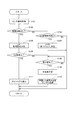
本実施形態の中点補正処理を図3のフローチャートに基づいて説明する。この処理は、IGがオフからオンに切り替わったときに、制御部150、250にて実行される。ここでは、第1制御部150での処理について説明する。なお、第2制御部250での処理は、自系統を第2系統L2とし、他系統を第1系統L1として、対応する構成や値を読み替えればよいので、説明を省略する。以下、ステップS101の「ステップ」を省略し、単に記号「S」と記す。第2実施形態も同様とする。
The midpoint correction process of the present embodiment will be described with reference to the flowchart of FIG. This process is executed by the
S101では、センサ通信部151は、第1回転角センサ120からセンサ信号を取得する。
S102では、第1制御部150は、第1回転角センサ120から取得されるセンサ信号に基づき、IGオフ中に電源失陥異常が生じたか否かを判断する。IGオフ中に電源失陥異常が生じたと判断された場合(S102:YES)、S105へ移行する。IGオフ中に電源失陥異常が生じていないと判断された場合(S102:NO)、S103へ移行する。IGオフ中の電源失陥異常がなかった場合、舵角演算部155は、IGオフ以前の舵角中点MP1を用いた舵角θs1の演算が可能である。
In S101, the
In S102, the
S103では、第1制御部150は、第2制御部250からの補正情報の取得要求があったか否かを判断する。補正情報には、回転回数および舵角中点が含まれる。以下、第1系統L1の回転回数TC1および舵角中点MP1を「補正情報CI1」、第2系統L2の回転回数TC2および舵角中点MP2を「補正情報CI2」とする。補正情報CI1の取得要求があったと判断された場合(S103:YES)、S104へ移行し、第1制御部150は、回転回数TC1および舵角中点MP1を補正情報CI1として第2制御部250に送信する。補正情報CI1の取得要求がないと判断された場合(S103:NO)、補正情報CI1の送信を行わない。
ここでは、第2系統L2への補正情報CI1の送信処理についても、本処理に含まれるものとして説明したが、S103およびS104の処理を、別途の処理にて行うようにしてもよい。
In S103, the
Here, the process of transmitting the correction information CI1 to the second system L2 has also been described as being included in this process, but the processes of S103 and S104 may be performed by separate processes.
IGオフ中の電源失陥異常があったと判断された場合(S102:YES)に移行するS105では、第1制御部150は、補正情報CI2の取得要求を第2制御部250に送信する。補正情報の取得要求は、マイコン間通信にて第2制御部250に送信してもよいし、車両通信網300を介して第2制御部250に送信してもよい。S104も同様である。
In S105, which shifts to the case where it is determined that there is a power failure abnormality during IG off (S102: YES), the
S106では、第1制御部150は、第2制御部250から補正情報CI2を取得できたか否かを判断する。例えば、第2系統L2においても電源失陥異常が生じた場合やマイコン間通信が異常である場合、第1制御部150は第2制御部250から補正情報CI2を取得することができない。
補正情報CI2を取得できたと判断された場合(S106:YES)、S107へ移行する。補正情報CI1を取得できなかったと判断された場合(S106:NO)、S108へ移行する。
S107では、第1制御部150は、補正情報CI2を第1回転角センサ120に送信する。第1回転角センサ120では、受信した補正情報CI2に基づき、現在の回転回数TC1および舵角中点MP1を書き換える。
In S106, the
When it is determined that the correction information CI2 can be acquired (S106: YES), the process proceeds to S107. If it is determined that the correction information CI1 could not be acquired (S106: NO), the process proceeds to S108.
In S107, the
S108では、第1制御部150は、舵角中点MP1の再学習が可能か否かを判断する。車両が所定速度以上で直進しているとき、舵角中点MP1の再学習が可能と判断する。車両の直進判定は、例えば車輪速センサ311の検出値、GPS受信機312からのGPS情報、および、車載カメラ313のデータ等に基づいて判定可能である。舵角中点MP1の再学習ができないと判断された場合(S108:NO)、この判断処理を繰り返す。舵角中点MP1の再学習が可能であると判断された場合(S108:YES)、S109へ移行する。
In S108, the
S109では、第1制御部150は、車両直進時の回転回数TC1に基づき、舵角中点MP1を再学習する。
S110では、第1制御部150は、再学習した舵角中点MP1を第1回転角センサ120に送信する。第1回転角センサ120では、再学習された舵角中点MP1に応じ、現在の回転回数TC1および舵角中点MP1の少なくとも一方を書き換える。
In S109, the
In S110, the
本実施形態では、IGオフ中に第1系統L1にて電源失陥異常が生じたとしても、第2系統L2が正常であれば、IGがオンされたとき、第1制御部150は、第2制御部250から補正情報CI2として舵角中点MP2および回転回数TC2を取得する。そして、第1制御部150は、舵角中点MP2および回転回数TC2を第1回転角センサ120に送信する。第1回転角センサ120では、舵角中点MP2および回転回数TC2に基づき、舵角中点MP1および回転回数TC1を書き換える。第1系統L1が正常であり、第2系統L2にて電源失陥異常が生じた場合、第2制御部250は、第1制御部150から補正情報CI2として舵角中点MP1および回転回数TC1を取得し、舵角中点MP2および回転回数TC2を補正する。
これにより、直進走行を伴う舵角中点MP1、MP2の再学習が不要になるので、部品の追加等をすることなく、電源失陥異常時の舵角中点MP1、MP2の補正処理を高速化することができる。
In the present embodiment, even if a power failure abnormality occurs in the first system L1 while the IG is off, if the second system L2 is normal, the
This eliminates the need for re-learning of the steering angle midpoints MP1 and MP2 that accompany straight running, so that the correction processing of the steering angle midpoints MP1 and MP2 in the event of a power failure abnormality can be performed at high speed without adding parts. Can be transformed into.
以上説明したように、本実施形態の舵角検出装置11は、複数の回転角センサ120、220と、複数の制御部150、250と、を備える。
第1回転角センサ120は、センサ素子121、122、回転角演算部123、124、ターンカウンタ125、および、通信部128を有する。
第2回転角センサ220は、センサ素子221、222、回転角演算部223、224、ターンカウンタ225、および、通信部228を有する。
センサ素子121、122、221、222は、減速ギア89を介してステアリングシステム90と連結されるモータ80の回転状態を検出する。
As described above, the steering
The first
The second
The
回転角演算部123、124は、センサ素子121、122の検出信号に基づいてモータ80の回転角θm1を演算する。回転角演算部223、224は、センサ素子221、222の検出信号に基づいてモータ80の回転角θm2を演算する。
ターンカウンタ125は、センサ素子121、122の検出信号に基づいてモータ80の回転回数TC1を演算する。ターンカウンタ225は、センサ素子221、222の検出信号に基づいてモータ80の回転回数TC2を演算する。
The rotation
The
通信部128は、回転角θm1および回転回数TC1に係る情報を含むセンサ信号を出力する。通信部228は、回転角θm2および回転回数TC2に係る情報を含むセンサ信号を出力する。
回転角センサ120、220は、IGがオフされている期間において、少なくとも回転回数TC1、TC2の演算を継続可能である。
The
The
第1制御部150は、舵角演算部155を有する。舵角演算部155は、対応して設けられる第1回転角センサ120から取得される回転回数TC1および回転角θm1と、ステアリングホイール91の中立位置に係る舵角中点MP1とに基づいて舵角θs1を演算する。
第2制御部250は、舵角演算部255を有する。舵角演算部255は、対応して設けられる第2回転角センサ220から取得される回転回数TC2および回転角θm2と、ステアリングホイール91の中立位置に係る舵角中点MP2とに基づいて舵角θs2を演算する。
制御部150、250は、相互に情報を送受信可能である。
The
The
The
ここで、対応して設けられる回転角センサ120、220と制御部150、250との組み合わせを系統とする。本実施形態では、第1回転角センサ120と第1制御部150との組み合わせを第1系統L1、第2回転角センサ220と第2制御部250との組み合わせを第2系統L2とする。バッテリ170、270は、系統ごとに設けられる。
本実施形態では、回転角センサ120、220は、IGがオフされている期間において、舵角中点MP1、MP2を保持可能である。
Here, the combination of the
In the present embodiment, the
一部の系統において、IGがオフされている期間に回転角センサ120、220への電力供給が途絶えて回転回数TC1、TC2の演算が継続できなくなる電源失陥異常が生じた場合、電源失陥異常が生じた系統を異常系統、電源失陥異常が生じていない系統を正常系統とする。ここでは、第1系統L1を異常系統、第2系統L2を正常系統として説明する。
第1系統L1の制御部150は、IGがオンされたとき、第2系統L2の制御部250から、舵角中点MP2および回転回数TC2を取得する。
In some systems, if the power supply to the
When the IG is turned on, the
本実施形態では、バッテリ170、270を含めた舵角検出に係る構成が、独立して複数設けられる冗長構成となっているので、第1系統L1にて電源失陥異常が生じたとしても、第2系統L2の回転回数TC2および舵角中点MP2は正常である。制御部150、250は相互に通信可能であるので、第1制御部150は、第2制御部250から正常な舵角中点MP2および回転回数TC2を取得できる。したがって、第1系統L1では、舵角中点MP2および回転回数TC2に基づき、舵角θs1の演算に用いられる舵角中点MP1および回転回数TC1の少なくとも一方を補正することができる。これにより、一部の系統に電源失陥異常が生じた場合であっても、別途の部品等を追加することなく、適切に舵角演算を行うことができる。また、走行を伴う中立位置の再学習が不要であるので、異常系統における舵角演算再開までの時間を短縮することができる。
In the present embodiment, a plurality of independent configurations related to steering angle detection including the
異常系統である第1系統L1の第1制御部150は、正常系統である第2制御部250から取得した回転回数TC2および舵角中点MP2を、第1回転角センサ120に送信し、第1回転角センサ120にて回転回数TC1および舵角中点MP1を補正する。
これにより、第1系統L1にて舵角θs1の演算に用いられる値を適切に補正することができる。
本実施形態では、回転回数TC2および舵角中点MP2そのものが「補正情報」に対応する。
The
As a result, the value used in the calculation of the rudder angle θs1 in the first system L1 can be appropriately corrected.
In the present embodiment, the rotation speed TC2 and the steering angle midpoint MP2 itself correspond to the "correction information".
異常系統である第1系統L1の第1制御部150において、正常系統である第2系統L2の第2制御部250から舵角中点MP2および現在の回転回数TC2を取得できない場合、第1制御部150は、車両直進時の回転回数TC1に基づき、舵角中点MP1を再学習する。
これにより、第2制御部250から中点情報を取得できない場合において、舵角中点MP1を適切に再設定することができる。
When the
As a result, when the midpoint information cannot be acquired from the
(第2実施形態)
本実施形態の舵角検出装置を図4および図5に示す。本実施形態においても、第1系統L1が異常系統であり、第2系統L2が正常系統であるものとして説明する。
図4に示すように、舵角検出装置12は、センサユニット20、第1制御部160、および、第2制御部260を備える。
第1制御部160は、第1実施形態の第1制御部150の各構成に加え、舵角中点記憶部161を有する。舵角中点記憶部161は、ステアリングホイール91が中立状態となるときの回転回数TC1である舵角中点MP1が記憶される。
第2制御部260は、第1実施形態の第2制御部250の各構成に加え、舵角中点記憶部261を有する。舵角中点記憶部261は、ステアリングホイール91が中立状態となるときの回転回数TC2を舵角中点MP2が記憶される。
(Second Embodiment)
The steering angle detection device of this embodiment is shown in FIGS. 4 and 5. Also in this embodiment, it is assumed that the first system L1 is an abnormal system and the second system L2 is a normal system.
As shown in FIG. 4, the rudder
The
The
第1実施形態と同様、舵角中点MP1、MP2は、回転角センサ120、220の組み付け時にステアリングホイール91が中立位置となるように補正したときの回転回数「0」とする。本実施形態では、舵角中点記憶部161、261はROM等の不揮発性メモリとし、IGオフ中においても、舵角中点MP1、MP2が保持されるようにする。
Similar to the first embodiment, the steering angle midpoints MP1 and MP2 are set to the number of rotations "0" when the
本実施形態では、回転角センサ120、220のメモリ126、226には、舵角中点MP1、MP2は記憶されず、電源失陥異常を検出するためのフラグ等の情報が記憶される。例えば、電源失陥フラグの初期値を「0」とし、電力が供給されている場合、正常値「1」とする。メモリ126、226が揮発性メモリであれば、電源失陥異常が生じると、電源失陥フラグは初期値「0」に戻る。これにより、電源失陥異常を検出可能である。
第1実施形態においても、フラグ等により、電源失陥異常を検出するようにしてもよい。
In the present embodiment, the
Also in the first embodiment, the power failure abnormality may be detected by a flag or the like.
ここで、中点情報補正の具体例を説明する。
例えば、第1実施形態での説明と同様、IGがオフされる前において、TC1、TC2が10、舵角中点が0であったものとする。
IGがオフされている間に、第1系統L1に電源失陥異常が生じ、IGがオンされたときの回転回数TC1が10、回転回数TC2が20であるとする。この状態において、第1系統L1の舵角中点は、−10と計算することができる。
本実施形態では、舵角演算部155は、回転回数TC1=10、舵角中点MP1=−10が、回転回数TC1=20、舵角中点MP1=0となるように、第1回転角センサ120から受信した情報を内部的に読み替えて演算を行う。例えば、回転回数TC1に補正値Cv1=10を加算すれば、回転回数TC1=20と読み替え可能である。
Here, a specific example of midpoint information correction will be described.
For example, as in the description in the first embodiment, it is assumed that TC1 and TC2 are 10 and the steering angle midpoint is 0 before the IG is turned off.
It is assumed that a power failure abnormality occurs in the first system L1 while the IG is off, and the rotation speed TC1 is 10 and the rotation speed TC2 is 20 when the IG is turned on. In this state, the midpoint of the rudder angle of the first system L1 can be calculated as -10.
In the present embodiment, the rudder
本実施形態の中点補正処理を図5のフローチャートに基づいて説明する。この処理は、IGがオフからオンに切り替わったときに、制御部160、260にて実行される。ここでは、第1制御部160での処理について説明する。
本実施形態における中点補正処理は、S107に替えてS117とする点を除き、図3のフローチャートと同様である。
The midpoint correction process of the present embodiment will be described with reference to the flowchart of FIG. This process is executed by the
The midpoint correction process in the present embodiment is the same as the flowchart of FIG. 3 except that S117 is used instead of S107.
S106で肯定判断された場合に移行するS117では、第1制御部160は、電源失陥によるカウントずれを第1制御部160の内部にて補正する。
詳細には、第1制御部160は、第1回転角センサ120から取得された回転回数TC1と、第2制御部260から取得した回転回数TC2および舵角中点MP2とに基づき、回転回数TC1を補正するための補正値Cv1を演算する。舵角演算部155は、第1回転角センサ120から取得される回転回数TC1を補正値Cv1で補正して、舵角θs1を演算する。補正値Cv1は、電源失陥による舵角中点MP1のずれを補正するための値と捉えることもできる。
また、第1回転角センサ120から取得された回転回数TC1と、第2制御部260から取得した回転回数TC2および舵角中点MP2とに基づき、現在の回転回数TC1に応じた舵角中点MP1を演算し、舵角中点記憶部161に記憶されている舵角中点MP1の値を書き換えてもよい。
In S117, which shifts to the case where a positive judgment is made in S106, the
Specifically, the
Further, based on the rotation number TC1 acquired from the first
本実施形態では、異常系統である第1系統L1の第1制御部160は、正常系統である第2系統L2の第2制御部260から取得した舵角中点MP2および回転回数TC2に基づいて自系統の舵角中点MP1および回転回数TC1の少なくとも一方を補正する。また、舵角演算部155は、補正された値を用いて舵角θs1を演算する。
本実施形態では、第1制御部160の内部にて、電源失陥異常に伴う舵角中点のずれを補正している。このように構成しても、上記実施形態と同様の効果を奏する。
In the present embodiment, the
In the present embodiment, the deviation of the steering angle midpoint due to the power failure abnormality is corrected inside the
(他の実施形態)
上記実施形態では、回転角センサのメモリは、揮発性メモリである。他の実施形態では、回転角センサのメモリは不揮発性メモリであってもよい。この場合、別途の揮発性メモリ等の電源失陥異常を検出するための構成を設けることが望ましい。また、電源失陥異常の検出方法は、どのような方法であってもよい。
第1実施形態では、始動スイッチのオフ中に電源失陥異常が生じた場合、制御部から回転角センサに回転回数および舵角中点そのものを補正情報として送信し、回転角センサ側にて回転回数および舵角中点を補正している。他の実施形態では、回転角センサに送信される補正情報は、回転回数および舵角中点そのものに限らず、例えば、異常系統における回転回数のずれ量等の情報であってもよい。また、回転角センサ側では、中点情報または回転回数の一方を補正するようにしてもよい。
また、他の実施形態では、中点情報が回転角センサ側に保持されている場合であっても、第2実施形態のように、制御部側にて、回転回数および舵角中点を補正して舵角演算を行うようにしてもよい。
(Other embodiments)
In the above embodiment, the memory of the rotation angle sensor is a volatile memory. In other embodiments, the memory of the rotation angle sensor may be a non-volatile memory. In this case, it is desirable to provide a separate configuration for detecting a power failure abnormality such as a volatile memory. Further, any method may be used for detecting the power failure abnormality.
In the first embodiment, when a power failure abnormality occurs while the start switch is off, the control unit transmits the rotation speed and the steering angle midpoint itself as correction information, and the rotation angle sensor side rotates. The number of times and the midpoint of the rudder angle are corrected. In another embodiment, the correction information transmitted to the rotation angle sensor is not limited to the rotation speed and the steering angle midpoint itself, but may be, for example, information such as the deviation amount of the rotation speed in the abnormal system. Further, on the rotation angle sensor side, either the midpoint information or the number of rotations may be corrected.
Further, in the other embodiment, even when the midpoint information is held on the rotation angle sensor side, the rotation speed and the rudder angle midpoint are corrected on the control unit side as in the second embodiment. Then, the steering angle calculation may be performed.
第2実施形態では、始動スイッチのオフ中に電源失陥異常が生じた場合、制御部側にて回転回数および舵角中点を補正して舵角演算を行う。他の実施形態では、中点情報が制御部側にて保持されている場合であっても、第1実施形態のように、回転角センサに補正情報を送信し、回転角センサ側にて回転回数および中点情報の少なくとも一方を補正するようにしてもよい。
また、他の実施形態では、他の装置にて正確な舵角が分かる場合、他の装置から車両通信網を経由して取得される舵角情報に基づき、回転回数および中点情報の少なくとも一方を補正するようにしてもよい。
In the second embodiment, when a power failure abnormality occurs while the start switch is off, the control unit side corrects the number of revolutions and the midpoint of the steering angle to calculate the steering angle. In the other embodiment, even when the midpoint information is held on the control unit side, the correction information is transmitted to the rotation angle sensor and the rotation angle sensor side rotates as in the first embodiment. At least one of the number of times and the midpoint information may be corrected.
Further, in another embodiment, when the accurate steering angle is known by another device, at least one of the rotation speed and the midpoint information is based on the steering angle information acquired from the other device via the vehicle communication network. May be corrected.
上記実施形態では、制御部は2つである。他の実施形態では、制御部は3つ以上であってもよい。上記実施形態では、1つの制御部に対して1つの回転角センサが設けられる。他の実施形態では、1つの制御部に対して複数の回転角センサを設けてもよい。
上記実施形態では、回転角センサには、2つのセンサ素子、2つの回転角演算部、および、1つの回転回数演算部が設けられる。他の実施形態では、センサ素子、回転角演算部および回転回数演算部は、それぞれ1つ以上あれば、いくつずつとしてもよい。
上記実施形態では、舵角は、ステアリングシャフトの回転角である。他の実施形態では、舵角は、ステアリング角、ピニオン角、タイヤ角、モータ回転角の積算値等、どのギア時点の値としてもよい。
In the above embodiment, there are two control units. In other embodiments, the number of control units may be three or more. In the above embodiment, one rotation angle sensor is provided for one control unit. In other embodiments, a plurality of rotation angle sensors may be provided for one control unit.
In the above embodiment, the rotation angle sensor is provided with two sensor elements, two rotation angle calculation units, and one rotation speed calculation unit. In another embodiment, the number of the sensor element, the rotation angle calculation unit, and the rotation speed calculation unit may be one or more, respectively.
In the above embodiment, the steering angle is the rotation angle of the steering shaft. In another embodiment, the steering angle may be a value at any gear point such as a steering angle, a pinion angle, a tire angle, an integrated value of a motor rotation angle, and the like.
上記実施形態では、舵角検出装置は、電動パワーステアリング装置に用いられる。他の実施形態では、舵角検出装置を電動パワーステアリング装置以外の装置に適用してもよい。
以上、本発明は、上記実施形態になんら限定されるものではなく、発明の趣旨を逸脱しない範囲において種々の形態で実施可能である。
In the above embodiment, the steering angle detecting device is used for the electric power steering device. In other embodiments, the steering angle detection device may be applied to a device other than the electric power steering device.
As described above, the present invention is not limited to the above-described embodiment, and can be implemented in various embodiments without departing from the spirit of the invention.
11、12・・・舵角検出装置
80・・・モータ 89・・・減速ギア(動力伝達部)
90・・・ステアリングシステム
91・・・ステアリングホイール(操舵部材)
120、220・・・回転角センサ
121、122、221、222・・・センサ素子
123、124、223、224・・・回転角演算部
125、225・・・ターンカウンタ(回転回数演算部)
128、228・・・通信部
150、160、250、260・・・制御部
11, 12 ...
90 ...
120, 220 ...
128, 228 ...
Claims (4)
対応して設けられる前記回転角センサから取得される前記回転回数および前記回転角と、操舵部材(91)の中立位置に係る中点情報とに基づいて舵角を演算する舵角演算部(155、255)を有し、相互に情報を送受信可能である複数の制御部(150、250、160、260)と、
を備え、
対応して設けられる前記回転角センサと前記制御部との組み合わせを系統とし、電源(170、270)が系統ごとに設けられており、
前記回転角センサまたは前記制御部は、前記始動スイッチがオフされている期間において、前記中点情報を保持可能であって、
一部の系統において、前記始動スイッチがオフされている期間に前記回転角センサへの電力供給が途絶えて前記回転回数の演算が継続できなくなる電源失陥異常が生じた場合、前記電源失陥異常が生じた系統を異常系統、前記電源失陥異常が生じていない系統を正常系統とすると、
前記異常系統の前記制御部は、前記始動スイッチがオンされたとき、前記正常系統の前記制御部から前記中点情報および前記回転回数を取得し、
前記中点情報および前記回転回数の少なくとも一方は、他の装置から車両通信網を経由して取得される舵角情報に基づいて補正される舵角検出装置。 Sensor elements (121, 122, 221 and 222) that detect the rotational state of the motor (80) connected to the steering system (90) via the power transmission unit (89), and the sensor element based on the detection signal of the sensor element. A rotation angle calculation unit (123, 124, 223, 224) that calculates the rotation angle of the motor, a rotation number calculation unit (125, 225) that calculates the rotation number of the motor based on the detection signal of the sensor element, and It has a communication unit (128, 228) that outputs a sensor signal including information on the rotation angle and the number of rotations, and can continue to calculate at least the number of rotations while the start switch of the vehicle is off. With multiple rotation angle sensors (120, 220),
The steering angle calculation unit (155) calculates the steering angle based on the number of rotations and the rotation angle acquired from the corresponding rotation angle sensor and the midpoint information related to the neutral position of the steering member (91). , 255) and a plurality of control units (150, 250, 160, 260) capable of transmitting and receiving information to and from each other.
With
A combination of the rotation angle sensor and the control unit provided correspondingly is used as a system, and a power supply (170, 270) is provided for each system.
The rotation angle sensor or the control unit can hold the midpoint information during the period when the start switch is off.
In some systems, when a power failure abnormality occurs in which the power supply to the rotation angle sensor is interrupted and the calculation of the rotation speed cannot be continued while the start switch is off, the power failure abnormality occurs. If the system in which the above occurs is an abnormal system, and the system in which the power failure abnormality does not occur is a normal system
When the start switch is turned on, the control unit of the abnormal system acquires the midpoint information and the rotation speed from the control unit of the normal system .
A steering angle detecting device in which at least one of the midpoint information and the number of rotations is corrected based on steering angle information acquired from another device via the vehicle communication network .
前記異常系統の前記舵角演算部は、補正された値を用いて前記舵角を演算する請求項1に記載の舵角検出装置。 The control unit of the abnormal system corrects at least one of the midpoint information of its own system and the rotation speed based on the midpoint information and the rotation speed acquired from the control unit of the normal system.
The steering angle detecting device according to claim 1, wherein the steering angle calculation unit of the abnormal system calculates the steering angle using the corrected value.
前記異常系統の前記制御部は、車両直進時の前記回転回数に基づき、前記中点情報を再学習する請求項1〜3のいずれか一項に記載の舵角検出装置。 When the control unit of the abnormal system cannot obtain the midpoint information and the current rotation speed from the control unit of the normal system.
The steering angle detecting device according to any one of claims 1 to 3 , wherein the control unit of the abnormal system relearns the midpoint information based on the number of rotations when the vehicle goes straight.
Priority Applications (3)
| Application Number | Priority Date | Filing Date | Title |
|---|---|---|---|
| JP2017082352A JP6760192B2 (en) | 2017-04-18 | 2017-04-18 | Rudder angle detector |
| PCT/JP2018/015726 WO2018194029A1 (en) | 2017-04-18 | 2018-04-16 | Steering angle detection device |
| US16/654,314 US11465683B2 (en) | 2017-04-18 | 2019-10-16 | Steering angle detection device |
Applications Claiming Priority (1)
| Application Number | Priority Date | Filing Date | Title |
|---|---|---|---|
| JP2017082352A JP6760192B2 (en) | 2017-04-18 | 2017-04-18 | Rudder angle detector |
Publications (3)
| Publication Number | Publication Date |
|---|---|
| JP2018177099A JP2018177099A (en) | 2018-11-15 |
| JP2018177099A5 JP2018177099A5 (en) | 2019-07-25 |
| JP6760192B2 true JP6760192B2 (en) | 2020-09-23 |
Family
ID=63855862
Family Applications (1)
| Application Number | Title | Priority Date | Filing Date |
|---|---|---|---|
| JP2017082352A Active JP6760192B2 (en) | 2017-04-18 | 2017-04-18 | Rudder angle detector |
Country Status (3)
| Country | Link |
|---|---|
| US (1) | US11465683B2 (en) |
| JP (1) | JP6760192B2 (en) |
| WO (1) | WO2018194029A1 (en) |
Families Citing this family (4)
| Publication number | Priority date | Publication date | Assignee | Title |
|---|---|---|---|---|
| JP7047738B2 (en) * | 2018-12-07 | 2022-04-05 | 株式会社デンソー | Steering system |
| KR102637909B1 (en) * | 2019-01-23 | 2024-02-19 | 에이치엘만도 주식회사 | Redundancy circuit for electric power steering system |
| JP2023170518A (en) * | 2022-05-19 | 2023-12-01 | 株式会社デンソー | Rotation detecting device |
| JP2024014035A (en) * | 2022-07-21 | 2024-02-01 | 株式会社デンソー | sensor device |
Family Cites Families (12)
| Publication number | Priority date | Publication date | Assignee | Title |
|---|---|---|---|---|
| JP3390824B2 (en) * | 1997-03-19 | 2003-03-31 | 株式会社日立製作所 | Multiplexing control device and fault recovery method therefor |
| JP3575279B2 (en) | 1998-05-22 | 2004-10-13 | アイシン精機株式会社 | Parking assistance device |
| JP2001328552A (en) | 2000-05-22 | 2001-11-27 | Aisin Seiki Co Ltd | Steering angle neutral point detector for steering device |
| JP2004276834A (en) * | 2003-03-18 | 2004-10-07 | Toyoda Mach Works Ltd | Steering device for vehicle |
| JP2006322794A (en) | 2005-05-18 | 2006-11-30 | Hitachi Cable Ltd | Steering angle sensor |
| JP5574627B2 (en) * | 2009-06-12 | 2014-08-20 | 三菱重工業株式会社 | Redundant system |
| JP5389101B2 (en) | 2011-04-26 | 2014-01-15 | 三菱電機株式会社 | Motor control device |
| JP5941871B2 (en) * | 2013-05-28 | 2016-06-29 | 本田技研工業株式会社 | Electric power steering device |
| JP5726265B2 (en) * | 2013-10-23 | 2015-05-27 | 三菱電機株式会社 | Electric power steering control device |
| JP6419426B2 (en) * | 2013-12-19 | 2018-11-07 | 日本電産エレシス株式会社 | Electronic control unit for electric power steering |
| JP6128013B2 (en) | 2014-02-27 | 2017-05-17 | 株式会社デンソー | Rotation angle detection device and electric power steering device using the same |
| JP6657584B2 (en) * | 2015-03-31 | 2020-03-04 | 株式会社ジェイテクト | Rotation detection device, rotation angle detection device, and electric power steering device |
-
2017
- 2017-04-18 JP JP2017082352A patent/JP6760192B2/en active Active
-
2018
- 2018-04-16 WO PCT/JP2018/015726 patent/WO2018194029A1/en active Application Filing
-
2019
- 2019-10-16 US US16/654,314 patent/US11465683B2/en active Active
Also Published As
| Publication number | Publication date |
|---|---|
| JP2018177099A (en) | 2018-11-15 |
| US20200047806A1 (en) | 2020-02-13 |
| WO2018194029A1 (en) | 2018-10-25 |
| US11465683B2 (en) | 2022-10-11 |
Similar Documents
| Publication | Publication Date | Title |
|---|---|---|
| JP6926504B2 (en) | Rotation detector | |
| JP5635071B2 (en) | Electric power steering device | |
| JP6760192B2 (en) | Rudder angle detector | |
| US9365238B2 (en) | Electric power steering apparatus | |
| US10246127B2 (en) | Rotational angle detecting device and electric power steering device using the same | |
| US10717462B2 (en) | Sensor device and electric power steering device using same | |
| US10293856B2 (en) | Vehicular steering system | |
| EP2960141B1 (en) | Steering system | |
| US8967321B2 (en) | Electric power steering apparatus | |
| JP6747367B2 (en) | Rudder angle detection device and electric power steering device using the same | |
| US8798861B2 (en) | Electric power steering apparatus | |
| CN112026912B (en) | Automatic driving steering angle detection method and electronic equipment | |
| US20150051794A1 (en) | Steering Angle Detecting Apparatus for Vehicle and Electric Power Steering Apparatus | |
| EP3369644A1 (en) | Sensor device and electric power steering device | |
| JP2019207204A (en) | Rotation detector and electric power steering device using the same | |
| JP2009096325A (en) | Malfunction detecting device for steering device | |
| JP5867287B2 (en) | Steering angle detection device for vehicle and electric power steering device | |
| JP7255095B2 (en) | Rotation detection device and electric power steering device using the same | |
| JP2011000963A (en) | Steering device | |
| JP2008062686A (en) | Electric power steering control device and its control method | |
| JP4023301B2 (en) | Motor control device | |
| JP6024976B2 (en) | Steering angle sensor reliability determination device | |
| KR20120036203A (en) | Method for calculating steering angle in motor driven power steering system |
Legal Events
| Date | Code | Title | Description |
|---|---|---|---|
| A521 | Request for written amendment filed |
Free format text: JAPANESE INTERMEDIATE CODE: A523 Effective date: 20190617 |
|
| A621 | Written request for application examination |
Free format text: JAPANESE INTERMEDIATE CODE: A621 Effective date: 20190617 |
|
| A131 | Notification of reasons for refusal |
Free format text: JAPANESE INTERMEDIATE CODE: A131 Effective date: 20200512 |
|
| A521 | Request for written amendment filed |
Free format text: JAPANESE INTERMEDIATE CODE: A523 Effective date: 20200706 |
|
| TRDD | Decision of grant or rejection written | ||
| A01 | Written decision to grant a patent or to grant a registration (utility model) |
Free format text: JAPANESE INTERMEDIATE CODE: A01 Effective date: 20200804 |
|
| A61 | First payment of annual fees (during grant procedure) |
Free format text: JAPANESE INTERMEDIATE CODE: A61 Effective date: 20200817 |
|
| R151 | Written notification of patent or utility model registration |
Ref document number: 6760192 Country of ref document: JP Free format text: JAPANESE INTERMEDIATE CODE: R151 |
|
| R250 | Receipt of annual fees |
Free format text: JAPANESE INTERMEDIATE CODE: R250 |