JP6759598B2 - Projector and control method - Google Patents
Projector and control method Download PDFInfo
- Publication number
- JP6759598B2 JP6759598B2 JP2016008897A JP2016008897A JP6759598B2 JP 6759598 B2 JP6759598 B2 JP 6759598B2 JP 2016008897 A JP2016008897 A JP 2016008897A JP 2016008897 A JP2016008897 A JP 2016008897A JP 6759598 B2 JP6759598 B2 JP 6759598B2
- Authority
- JP
- Japan
- Prior art keywords
- projector
- unit
- image
- projectors
- projection
- Prior art date
- Legal status (The legal status is an assumption and is not a legal conclusion. Google has not performed a legal analysis and makes no representation as to the accuracy of the status listed.)
- Active
Links
Images


Description
この発明は、プロジェクター、及び制御方法に関する。 The present invention relates to a projector and a control method.
複数台のプロジェクターをネットワークに接続して使用する技術の開発や研究が行われている。 Technology is being developed and researched to connect multiple projectors to a network.
これに関し、特許文献1には、ネットワークに接続されている複数のプロジェクターの一覧をPC(Personal Computer)のディスプレイに表示させ、表示された当該一覧の中からユーザーが操作したい対象となるプロジェクターを選択することが記載されている。
Regarding this, in
しかしながら、従来の方法では、2以上のプロジェクターで連携して実行するコマンドを実行させる対象となるプロジェクターを複数のプロジェクターの中から選択するためには、PCを用いる必要があった。そのため、従来の方法では、プロジェクターの設定を行うために要する時間を短縮することが困難な場合があった。 However, in the conventional method, it is necessary to use a PC in order to select from a plurality of projectors a target projector for executing a command to be executed in cooperation with two or more projectors. Therefore, it may be difficult to reduce the time required to set the projector by the conventional method.
そこで本発明は、上記従来技術の問題に鑑みてなされたものであり、PCを用いることなく複数のプロジェクターのうちのユーザーが所望するプロジェクターにコマンドを実行させることができるプロジェクター、及び制御方法を提供する。 Therefore, the present invention has been made in view of the above-mentioned problems of the prior art, and provides a projector capable of causing a user of a plurality of projectors to execute a command to a desired projector without using a PC, and a control method. To do.
本発明の一態様は、第1画像を投写面に投写する投写部と、他のプロジェクターから、前記他のプロジェクターを識別する識別情報を受信する受信部と、前記受信部が受信した前記識別情報が示す前記他のプロジェクターから、前記投写部による前記第1画像の投写とともに第2画像を前記投写面に投写させるプロジェクターである従プロジェクターを選択する画面である選択画面を生成する画面生成部と、前記画面生成部が生成した前記選択画面を表示部により表示させる表示制御部と、前記表示制御部が前記表示部により表示させた前記選択画面に対する指示を受け付ける指示受付部と、前記指示受付部が受け付けた前記指示によって選択された前記従プロジェクターにコマンドを送信する送信部と、を備えるプロジェクターである。
この構成により、プロジェクターは、第1画像を投写部により投写面に投写し、他のプロジェクターから、他のプロジェクターを識別する識別情報を受信し、受信した識別情報が示す他のプロジェクターから、当該投写部による第1画像の投写とともに第2画像を投写面に投写させるプロジェクターである従プロジェクターを選択する画面である選択画面を生成し、生成した選択画面を表示部により表示させ、表示部により表示させた選択画面に対する指示を受け付け、受け付けた指示によって選択された従プロジェクターにコマンドを送信する。これにより、プロジェクターは、PCを用いることなく複数のプロジェクターのうちのユーザーが所望するプロジェクターにコマンドを実行させることができる。
また、本発明の他の態様は、プロジェクターであって、第1画像を投写面に投写する投写部と、複数のプロジェクターの中からタイリング投写における主プロジェクターとして選択された場合、前記複数のプロジェクターのうち通信可能な1以上のプロジェクターのそれぞれを識別する識別情報を、前記1以上のプロジェクターのそれぞれから受信する受信部と、前記受信部が受信した前記識別情報が示すプロジェクターの中から、前記第1画像とともにタイリング投写される画像を第2画像として前記投写面に投写させるプロジェクターをタイリング投写における従プロジェクターとして選択する画面である選択画面を生成する画面生成部と、前記画面生成部が生成した前記選択画面を表示部により表示させる表示制御部と、前記表示制御部が前記表示部により表示させた前記選択画面に対する指示を受け付ける指示受付部と、前記指示受付部が受け付けた前記指示によって選択された前記従プロジェクターにコマンドを送信する送信部と、を備え、前記識別情報には、前記1以上のプロジェクターのそれぞれが設置された位置を示す情報が含まれており、前記選択画面には、前記1以上のプロジェクターのそれぞれを示す情報とともに、前記1以上のプロジェクターのそれぞれが設置された位置を示す情報が含まれている、プロジェクターである。
また、本発明の他の態様は、プロジェクターにおいて、前記1以上のプロジェクターのそれぞれが設置された位置を示す情報には、前記従プロジェクターが設置された部屋を示す情報と、その部屋の中での位置を示す情報とが含まれている、構成が用いられてもよい。
One aspect of the present invention is a projection unit that projects a first image onto a projection surface, a reception unit that receives identification information for identifying the other projector from another projector, and the identification information received by the reception unit. A screen generator that generates a selection screen, which is a screen for selecting a secondary projector, which is a projector that projects a second image onto the projection surface together with the projection of the first image by the projection unit from the other projector indicated by. A display control unit that displays the selection screen generated by the screen generation unit by the display unit, an instruction reception unit that receives an instruction for the selection screen displayed by the display control unit by the display unit, and the instruction reception unit. It is a projector including a transmission unit that transmits a command to the sub-projector selected by the received instruction.
With this configuration, the projector projects the first image onto the projection surface by the projection unit, receives identification information for identifying the other projector from the other projector, and projects the first image from the other projector indicated by the received identification information. A selection screen is generated, which is a screen for selecting a secondary projector, which is a projector that projects a second image on a projection surface together with the projection of the first image by the unit, and the generated selection screen is displayed by the display unit and displayed by the display unit. Accepts instructions for the selected screen and sends commands to the secondary projector selected by the accepted instructions. As a result, the projector can execute a command to a projector desired by a user among a plurality of projectors without using a PC.
Another aspect of the present invention is a projector, and a projection unit that projects the first image on the projection surface, if selected as the main projector according tiling projection from a plurality of projectors, said plurality of flops identification information for identifying, respectively it can communicate one or more projectors of projector, a receiver for receiving from each of the one or more projectors, the identification information received by the receiving unit is shown in to the projector from within, and the screen generating unit for generating a selection screen is a screen for selecting a sub projector in the image the tiling projects the pulp projector is projected on the projection surface as a second image to be tiled projection with the first image , A display control unit that displays the selection screen generated by the screen generation unit by the display unit, an instruction reception unit that receives an instruction for the selection screen displayed by the display control unit, and the instruction reception unit. and a transmission unit for transmitting a command to the slave projector selected by the instruction is accepted, to the identification information, each of said one or more projector is contains information indicating the installation position cage, the selection screen, the together with information indicating the respective one or more projectors, each of said one or more projector is included information indicating the installation position, a projector.
Another aspect of the present invention, in the projector, to the one or more information indicating a location at which each is installed in the projector includes information indicating the room where the slave projector is installed, in the room A configuration may be used that includes information indicating the location of the.
また、本発明の他の態様は、プロジェクターにおいて、前記送信部は、前記従プロジェクターに実行させる前記コマンドを、自装置との接続が確立した前記従プロジェクターに送信する、構成が用いられてもよい。
この構成により、プロジェクターは、従プロジェクターに実行させるコマンドを、自装置との接続が確立した従プロジェクターに送信する。これにより、プロジェクターは、自装置との接続が確立した従プロジェクターにコマンドを実行させることができる。
Further, in another aspect of the present invention, in the projector, the transmission unit may transmit the command to be executed by the slave projector to the slave projector whose connection with the own device is established. ..
With this configuration, the projector transmits a command to be executed by the slave projector to the slave projector whose connection with the own device is established. As a result, the projector can cause the sub-projector whose connection with the own device has been established to execute the command.
また、本発明の他の態様は、プロジェクターにおいて、前記表示部は、前記投写部を含み、前記表示制御部は、前記画面生成部が生成した前記選択画面を前記投写部に投写させることにより前記投写面に表示させる、構成が用いられてもよい。
この構成により、プロジェクターは、生成した選択画面を投写部に投写させることにより投写面に表示させる。これにより、プロジェクターは、投写面に表示させた選択画面に対する指示を受け付け、受け付けた指示に基づいて複数のプロジェクターのうちのユーザーが所望するプロジェクターにコマンドを実行させることができる。
In another aspect of the present invention, in the projector, the display unit includes the projection unit, and the display control unit projects the selection screen generated by the screen generation unit onto the projection unit. A configuration may be used that displays on the projection surface.
With this configuration, the projector displays the generated selection screen on the projection surface by projecting it on the projection unit. As a result, the projector can receive instructions for the selection screen displayed on the projection surface, and can cause the user of the plurality of projectors to execute a command based on the received instructions.
また、本発明の他の態様は、プロジェクターにおいて、前記表示部は、自装置に設けられた表示装置を含み、前記表示制御部は、前記画面生成部が生成した前記選択画面を前記表示装置に表示させる、構成が用いられてもよい。
この構成により、プロジェクターは、生成した選択画面を表示装置に表示させる。これにより、プロジェクターは、表示装置に表示させた選択画面に対する指示を受け付け、受け付けた指示に基づいて複数のプロジェクターのうちのユーザーが所望するプロジェクターにコマンドを実行させることができる。
Further, in another aspect of the present invention, in the projector, the display unit includes a display device provided in the own device, and the display control unit uses the selection screen generated by the screen generation unit as the display device. The configuration to be displayed may be used.
With this configuration, the projector causes the display device to display the generated selection screen. As a result, the projector can receive an instruction for the selection screen displayed on the display device, and can make the projector desired by the user among the plurality of projectors execute a command based on the received instruction.
また、本発明の他の態様は、第1画像を投写面に投写する投写部を備える主プロジェクターの制御方法であって、前記第1画像を前記投写部により前記投写面に投写し、他のプロジェクターから、前記他のプロジェクターを識別する識別情報を受信し、受信した前記識別情報が示す前記他のプロジェクターから、前記投写部による前記第1画像の投写とともに第2画像を前記投写面に投写させるプロジェクターである従プロジェクターを選択す画面である選択画面を生成し、生成した前記選択画面を表示部により表示させ、表示させた前記選択画面に対する指示を受け付け、受け付けた前記指示によって選択された前記従プロジェクターにコマンドを送信する、制御方法である。
この構成により、制御方法は、第1画像を投写部により投写面に投写し、他のプロジェクターから、他のプロジェクターを識別する識別情報を受信し、受信した識別情報が示す他のプロジェクターから、投写部による第1画像の投写とともに第2画像を投写面に投写させるプロジェクターである従プロジェクターを選択する画面である選択画面を生成し、生成した選択画面を表示部により表示させ、表示させた選択画面に対する指示を受け付け、受け付けた指示によって選択された従プロジェクターにコマンドを送信する。これにより、制御方法は、PCを用いることなく複数のプロジェクターのうちのユーザーが所望する主プロジェクターにコマンドを実行させることができる。
また、本発明の他の態様は、第1画像を投写面に投写する投写部を備える主プロジェクターの制御方法であって、前記制御方法は、前記第1画像を前記投写部により前記投写面に投写し、複数の他のプロジェクターのうち通信可能な1以上の前記他のプロジェクターのそれぞれから、前記他のプロジェクターを識別する識別情報を受信し、受信した前記識別情報が示す前記他のプロジェクターの中から、前記第1画像とともにタイリング投写される画像を第2画像として前記投写面に投写させる前記他のプロジェクターをタイリング投写における従プロジェクターとして選択する画面である選択画面を生成し、生成した前記選択画面を表示部により表示させ、表示させた前記選択画面に対する指示を受け付け、受け付けた前記指示によって選択された前記従プロジェクターにコマンドを送信し、前記識別情報には、前記1以上の前記他のプロジェクターのそれぞれが設置された位置を示す情報が含まれており、前記選択画面には、前記1以上の前記他のプロジェクターのそれぞれを示す情報とともに、前記1以上の前記他のプロジェクターのそれぞれが設置された位置を示す情報が含まれている、制御方法である。
また、本発明の他の態様は、制御方法において、前記1以上の前記プロジェクターのそれぞれが設置された位置を示す情報には、前記従プロジェクターが設置された部屋を示す情報と、その部屋の中での位置を示す情報とが含まれている、構成が用いられてもよい。
また、本発明の他の態様は、制御方法において、前記従プロジェクターに実行させる前記コマンドを、前記主プロジェクターとの接続が確立した前記従プロジェクターに送信する、構成が用いられてもよい。
また、本発明の他の態様は、制御方法において、前記表示部は、前記投写部を含み、生成した前記選択画面を前記投写部に投写させることにより前記投写面に表示させる、構成が用いられてもよい。
また、本発明の他の態様は、制御方法において、前記表示部は、前記主プロジェクターに設けられた表示装置を含み、生成した前記選択画面を前記表示装置に表示させる、構成が用いられてもよい。
Another aspect of the present invention is a control method of a main projector including a projection unit that projects a first image onto a projection surface, wherein the first image is projected onto the projection surface by the projection unit, and another aspect is used. The identification information that identifies the other projector is received from the projector, and the second image is projected onto the projection surface together with the projection of the first image by the projection unit from the other projector indicated by the received identification information. A selection screen, which is a screen for selecting a secondary projector which is a projector, is generated, the generated selection screen is displayed by a display unit, an instruction for the displayed selection screen is received, and the slave selected by the received instruction is received. This is a control method that sends commands to the projector.
With this configuration, the control method projects the first image onto the projection surface by the projection unit, receives identification information that identifies the other projector from another projector, and projects it from another projector indicated by the received identification information. A selection screen is generated, which is a screen for selecting a secondary projector, which is a projector that projects a second image on the projection surface together with the projection of the first image by the unit, and the generated selection screen is displayed by the display unit and displayed. The command is received and the command is sent to the sub-projector selected by the received instruction. Thereby, the control method can make the main projector desired by the user among the plurality of projectors execute the command without using a PC.
Another aspect of the present invention is a control method of a main projector including a projection unit for projecting a first image onto a projection surface, wherein the control method causes the first image to be projected onto the projection surface by the projection unit. Among the other projectors that project and receive identification information for identifying the other projector from each of the one or more communicable other projectors among the plurality of other projectors, and the received identification information indicates. From the above, a selection screen is generated, which is a screen for selecting the other projector for projecting the image projected by tying together with the first image as the second image on the projection surface as a secondary projector in the tying projection. The selection screen is displayed by the display unit, an instruction for the displayed selection screen is received, a command is transmitted to the sub-projector selected by the received instruction, and the identification information includes the one or more of the other. Information indicating the position where each of the projectors is installed is included, and the selection screen includes information indicating each of the one or more other projectors, and each of the one or more other projectors is installed. It is a control method that includes information indicating the position where the projector is moved.
Further, in another aspect of the present invention, in the control method, the information indicating the position where each of the one or more projectors is installed includes the information indicating the room in which the secondary projector is installed and the inside of the room. A configuration may be used that includes information indicating its position at.
Further, in another aspect of the present invention, in the control method, a configuration may be used in which the command to be executed by the sub-projector is transmitted to the sub-projector for which a connection with the main projector has been established.
Further, in another aspect of the present invention, in the control method, the display unit includes the projection unit, and the generated selection screen is projected onto the projection unit to be displayed on the projection surface. You may.
Further, in another aspect of the present invention, even if a configuration is used in which the display unit includes a display device provided in the main projector and the generated selection screen is displayed on the display device in the control method. Good.
以上により、プロジェクター、及び制御方法は、第1画像を投写部により投写面に投写し、他のプロジェクターから、他のプロジェクターを識別する識別情報を受信し、受信した識別情報が示す他のプロジェクターから、投写部による第1画像の投写とともに第2画像を投写面に投写させるプロジェクターである従プロジェクターを選択する画面である選択画面を生成し、生成した選択画面を表示部により表示させ、表示させた選択画面に対する指示を受け付け、受け付けた指示によって選択された従プロジェクターにコマンドを送信する。これにより、プロジェクター、及び制御方法は、PCを用いることなく複数のプロジェクターのうちのユーザーが所望するプロジェクターにコマンドを実行させることができる。 As described above, the projector and the control method project the first image on the projection surface by the projection unit, receive the identification information for identifying the other projector from the other projector, and from the other projector indicated by the received identification information. , A selection screen, which is a screen for selecting a secondary projector, which is a projector that projects a second image on the projection surface together with the projection of the first image by the projection unit, is generated, and the generated selection screen is displayed and displayed on the display unit. Accepts instructions for the selection screen and sends commands to the secondary projector selected by the accepted instructions. Thereby, the projector and the control method can make the projector desired by the user among the plurality of projectors execute the command without using a PC.
<実施形態>
以下、本発明の実施形態について、図面を参照して説明する。
<Embodiment>
Hereinafter, embodiments of the present invention will be described with reference to the drawings.
<プロジェクターシステムの構成>
まず、本実施形態に係るプロジェクターシステム1の構成について説明する。図1は、プロジェクターシステム1の構成の一例を示す図である。プロジェクターシステム1は、複数のプロジェクター10と、HUB30を備える。以下では、一例として、プロジェクターシステム1が図1に示した4台のプロジェクター10、すなわちプロジェクター10−1〜プロジェクター10−4と、これらのプロジェクター10が設置された部屋と異なる部屋に設置された1以上の図示しない他のプロジェクター10とを備える場合について説明する。なお、プロジェクターシステム1は、これに代えて、当該他のプロジェクター10を備えない構成であってもよく、当該4台のプロジェクター10のうちの一部を備えない構成であってもよい。
<Projector system configuration>
First, the configuration of the
プロジェクター10は、図示しない液晶パネルと、図示しない光源と、図示しない投写レンズを備える。プロジェクター10は、入力される投写画像に応じた駆動電圧を図示しない液晶パネルの各画素に印加(駆動)する。この印加によって、液晶パネルは、図示しない光源から液晶パネルへ入射した光を、画像情報に応じた画像を映し出す光として形成する。プロジェクター10は、光源が放射した光を液晶パネル側に反射するリフレクターを有し、反射した光を画像情報に応じた画像を映し出す光として液晶パネルに形成させる。そして、プロジェクター10は、液晶パネルに形成された画像を映し出す光を、図示しない投写レンズを通してスクリーンSCに投写する。
The
ここで、図示しない光源は、例えば、超高圧水銀ランプやメタルハライドランプ等からなる放電型の光源ランプであるが、光源ランプに限られず、LED(Light Emitting Diode)光源やレーザー光源等を用いてもよい。液晶パネルは、例えば、一対の透明基板間に液晶が封入された、光の三原色であるRGBそれぞれに対応した透過型の液晶パネルである。なお、液晶パネルは、透過型の液晶パネルに限られず、反射型の液晶パネルであってもよい。また、プロジェクター10は、液晶パネルを備える構成に代えて、DMD(Digital Mirror Device)等を備える構成であってもよい。
Here, the light source (not shown) is, for example, a discharge type light source lamp composed of an ultra-high pressure mercury lamp, a metal halide lamp, or the like, but is not limited to the light source lamp, and an LED (Light Emitting Diode) light source, a laser light source, or the like may be used. Good. The liquid crystal panel is, for example, a transmissive liquid crystal panel in which a liquid crystal is enclosed between a pair of transparent substrates and corresponding to each of the three primary colors of light, RGB. The liquid crystal panel is not limited to the transmissive type liquid crystal panel, and may be a reflective type liquid crystal panel. Further, the
プロジェクター10は、ケーブルによってHUB30と通信可能に接続され、HUB30を介して他のプロジェクター10と通信可能に接続されている。ケーブルを介した有線通信は、例えば、イーサネット(登録商標)やUSB(Universal Serial Bus)等の規格によって行われる。なお、4台のプロジェクター10のうちの一部又は全部は、Wi−Fi(登録商標)等の通信規格により行われる無線通信によって当該無線通信を中継するルーター等と接続される構成であってもよく、Wi−Fi(登録商標)等の通信規格により行われる無線通信によって他の装置を介さずに互いに接続される構成であってもよい。
The
この一例では、複数のプロジェクター10のそれぞれが互いに同じ構成である場合について説明する。なお、複数のプロジェクター10の一部又は全部は、互いに異なる構成であってもよい。この場合、複数のプロジェクター10のそれぞれは、少なくとも本実施形態において説明するプロジェクター10の構成を有する。
In this example, a case where each of the plurality of
HUB30は、イーサネット(登録商標)やUSB等の規格によって行われる有線通信を中継する通信装置である。また、HUB30は、図示しないネットワークに接続されている。当該ネットワークは、例えば、図1に示した4台のプロジェクター10が設置された建物に敷設されたLAN(Local Area Network)である。なお、当該ネットワークは、これに代えて、WAN(Wide Area Network)等の他のネットワークであってもよい。HUB30には、上記の4台のプロジェクター10に加えて、他のプロジェクター10がネットワークを介して接続されている。すなわち、上記の4台のプロジェクター10のそれぞれは、当該他のプロジェクター10とも通信可能に接続されている。この一例では、当該他のプロジェクター10は、上記の4台のプロジェクター10が設置されている部屋とは異なる部屋に設置されている場合について説明する。なお、HUB30は、当該有線通信を中継するルーターであってもよい。
The
<プロジェクターが行う処理の概要>
以下、プロジェクターシステム1においてプロジェクター10が行う処理の概要について説明する。
<Outline of processing performed by the projector>
Hereinafter, the outline of the processing performed by the
この一例におけるプロジェクターシステム1では、図1に示した4台のプロジェクター10が連携してタイリング投写を行うことにより投写面に投写画像P0を表示させる。タイリング投写は、複数のプロジェクターのそれぞれが投写する画像を投写面に並べて1枚の画像を表示させることである。投写面は、この一例において、スクリーンSCである。なお、投写面は、スクリーンSCに代えて、壁面や床面、天井、他の物体の表面であってもよい。
In the
図1に示した例では、投写画像P0を4つに分割した部分画像のうちの部分画像P1をプロジェクター10−1が投写し、部分画像P2をプロジェクター10−2が投写し、部分画像P3をプロジェクター10−3が投写し、部分画像P4をプロジェクター10−4が投写している。また、プロジェクター10−1〜プロジェクター10−4のそれぞれは、部分画像P1〜部分画像P4のそれぞれをスクリーンSC上において2行2列に並ぶように投写する。この一例では、部分画像P1が当該2行2列の左上、部分画像P2が当該2行2列の右上、部分画像P3が当該2行2列の左下、部分画像P4が当該2行2列の右下に並べられている。ここで、左右上下は、スクリーンSCに向かって見た場合の方向を表している。このようなタイリング投写により、プロジェクターシステム1は、スクリーンSCに投写画像P0を表示させる。投写画像P0は、この一例において、楕円Cが描かれた画像である。なお、投写画像P0は、当該画像に代えて、他の画像であってもよい。
In the example shown in FIG. 1, the projector 10-1 projects the partial image P1 of the partial images obtained by dividing the projected image P0 into four, the projector 10-2 projects the partial image P2, and the partial image P3 is projected. Projector 10-3 projects, and projector 10-4 projects partial image P4. Further, each of the projectors 10-1 to 10-4 projects the partial images P1 to the partial images P4 so as to be arranged in 2 rows and 2 columns on the screen SC. In this example, the partial image P1 is in the upper left of the 2 rows and 2 columns, the partial image P2 is in the upper right of the 2 rows and 2 columns, the partial image P3 is in the lower left of the 2 rows and 2 columns, and the partial image P4 is in the 2 rows and 2 columns. They are lined up in the lower right. Here, the left, right, top, and bottom represent the directions when viewed toward the screen SC. By such tiling projection, the
この一例では、プロジェクター10−1〜プロジェクター10−4のそれぞれは、部分画像P1〜部分画像P4のそれぞれが互いに重ならないように投写している。しかし、これは一例に過ぎず、プロジェクターシステム1では、プロジェクター10−1〜プロジェクター10−4のそれぞれが、部分画像P1〜部分画像P4のそれぞれの少なくとも一部が互いに重なるように投写する構成であってもよい。
In this example, each of the projectors 10-1 to 10-4 projects the partial images P1 to the partial images P4 so as not to overlap each other. However, this is only an example, and in the
このようなタイリング投写を行っている間においてプロジェクターシステム1では、HUB30に接続された複数のプロジェクター10の中から、ユーザーによって選択された主プロジェクター(ホストプロジェクター)によって、主プロジェクターとともにタイリング投写を行っている他のプロジェクター10が選択(特定)される。主プロジェクターは、この一例において、図1に示した4台のプロジェクター10のうちのいずれかである。なお、主プロジェクターは、これに代えて、図1に示したプロジェクター10と異なる他のプロジェクター10であってもよい。以下では、説明の便宜上、ユーザーによって選択された主プロジェクターがプロジェクター10−1である場合について説明する。
While performing such tiling projection, the
以下では、説明の便宜上、主プロジェクターが投写する画像を第1画像と称し、主プロジェクター以外のプロジェクター10であってユーザーによって選択されたプロジェクター10である従プロジェクターが投写する画像を第2画像と称して説明する。
In the following, for convenience of explanation, the image projected by the main projector is referred to as a first image, and the image projected by a secondary projector which is a
タイリング投写において、この一例における主プロジェクターであるプロジェクター10−1は、第1画像である部分画像P1をスクリーンSCに投写する。また、プロジェクター10−1は、HUB30を介して通信可能な他のプロジェクター10から、当該他のプロジェクター10を識別する識別情報を受信する。例えば、プロジェクター10−1は、プロジェクター10−1が設置された部屋と同じ部屋に設置された他のプロジェクター10であるプロジェクター10−2〜プロジェクター10−4のそれぞれから識別情報を受信する。また、例えば、プロジェクター10−1は、プロジェクター10−1が設置されている部屋と異なる部屋に設置されたプロジェクター10から識別情報を受信する。
In tiling projection, the projector 10-1, which is the main projector in this example, projects the partial image P1 which is the first image on the screen SC. Further, the projector 10-1 receives identification information for identifying the
なお、プロジェクター10−1は、HUB30を介して通信可能な他のプロジェクター10のうちの一部のプロジェクター10から、当該一部のプロジェクター10の識別情報を受信する構成であってもよい。当該一部のプロジェクター10は、例えば、プロジェクター10−1が属しているセグメントと同じセグメントに属している他のプロジェクター10のことである。
The projector 10-1 may be configured to receive the identification information of the part of the
識別情報は、例えば、IP(Internet Protocol)アドレスやMAC(Media Access Control)アドレス、プロジェクターID、型番号等を含む情報である。以下では、一例として、識別情報が、IPアドレスと、IPアドレスが示すプロジェクター10の名前を示す情報と、IPアドレスが示すプロジェクター10に関するコメントを示す情報とが対応付けられた情報である場合について説明する。当該コメントを示す情報は、例えば、IPアドレスが示すプロジェクター10が設置されている部屋番号等についてのコメントを示す情報である。
The identification information is information including, for example, an IP (Internet Protocol) address, a MAC (Media Access Control) address, a projector ID, a model number, and the like. In the following, as an example, a case where the identification information is the information in which the IP address, the information indicating the name of the
プロジェクター10−1は、受信した識別情報が示す他のプロジェクター10から、プロジェクター10−1による第1画像の投写とともに第2画像をスクリーンSCに投写させるプロジェクター10である従プロジェクターを選択する画面である選択画面を生成する。例えば、従プロジェクターがプロジェクター10−2であった場合、第2画像は、プロジェクター10−2が投写する部分画像P2である。また、従プロジェクターがプロジェクター10−3であった場合、第2画像は、プロジェクター10−3が投写する部分画像P3である。また、従プロジェクターがプロジェクター10−4であった場合、第2画像は、プロジェクター10−4が投写する部分画像P4である。
The projector 10-1 is a screen for selecting a secondary projector, which is a
プロジェクター10−1は、生成した選択画面を表示部により表示させる。当該表示部については、後述する。プロジェクター10−1は、当該表示部により表示させた選択画面に対する指示を受け付ける。プロジェクター10は、受け付けた指示によって選択された従プロジェクターにコマンドを送信する。これにより、プロジェクター10は、PCを用いることなく複数のプロジェクター10のうちのユーザーが所望するプロジェクター10にコマンドを実行させることができる。以下では、一例として、ユーザーに従プロジェクターとして選択されたプロジェクター10が、図1に示したプロジェクター10−2〜プロジェクター10−4の3台のプロジェクター10である場合について説明する。
The projector 10-1 displays the generated selection screen on the display unit. The display unit will be described later. The projector 10-1 receives an instruction for the selection screen displayed by the display unit. The
コマンドは、この一例において、タイリング投写における個体差補正処理を実行させる命令である。個体差補正処理は、各プロジェクター10がスクリーンSCに投写する部分画像の輝度、色相、コントラスト、カラーモード、黒レベル等の画質に関わる設定値を、所定の設定値に調整する処理である。すなわち、ユーザーは、タイリング投写を行っている間において、プロジェクター10−1とともにタイリング投写を行っているプロジェクター10を従プロジェクターとして選択画面から選択する。そして、プロジェクター10−1は、ユーザーにより選択された従プロジェクターとして選択(特定)されたプロジェクター10に、タイリング投写における個体差補正処理を実行させるコマンドを送信する。これにより、プロジェクター10−1、すなわち主プロジェクターは、主プロジェクターとともにタイリング投写を行っている従プロジェクターから投写された画像間の輝度、色相、コントラスト、カラーモード、黒レベル等の画質に関わる設定値の違い(個体差)を無くすように従プロジェクターに調整させることができる。なお、コマンドは、個体差補正処理を実行させる命令に代えて、例えば、タイリング投写において画像を切り替えるタイミングを同期させる同期処理等のように、複数のプロジェクター10のそれぞれに連携した動作を実行させる命令であれば、他の命令であってもよい。
The command is a command to execute the individual difference correction process in the tiling projection in this example. The individual difference correction process is a process of adjusting set values related to image quality such as brightness, hue, contrast, color mode, and black level of a partial image projected on the screen SC by each
以下では、プロジェクター10が選択画面を生成して表示部により表示させる処理と、プロジェクター10が選択画面から受け付けた指示によって選択された従プロジェクターにコマンドを送信する処理とについて詳しく説明する。
Hereinafter, the process of generating the selection screen by the
<プロジェクターの機能構成>
以下、図2を参照し、プロジェクター10の機能構成について説明する。図2は、プロジェクター10の機能構成の一例を示す図である。プロジェクター10は、撮像部11と、記憶部12と、操作受付部13と、通信部14と、表示部15と、制御部16と、画像処理部17と、画像入力部18を備える。
<Functional configuration of projector>
Hereinafter, the functional configuration of the
撮像部11は、例えば、集光された光を電気信号に変換する撮像素子であるCCD(Charge Coupled Device)やCMOS(Complementary Metal Oxide Semiconductor)等を備えたカメラである。この一例において、撮像部11は、タイリング投写によってスクリーンSCに投写された投写画像P0の全体を含む範囲を撮像可能な位置に設けられている。
The
記憶部12は、例えば、HDD(Hard Disk Drive)やSSD(Solid State Drive)、EEPROM(Electrically Erasable Programmable Read−Only Memory)、ROM(Read−Only Memory)、RAM(Random Access Memory)等を含む。なお、記憶部12は、プロジェクター10に内蔵されるものに代えて、USB等のデジタル入出力ポート等によって接続された外付け型の記憶装置であってもよい。記憶部12は、プロジェクター10が処理する各種情報や画像、プログラムを格納する。
The
操作受付部13は、例えば、表示部15と一体に構成されたタッチパネルである。なお、操作受付部13は、キーボードやマウス、タッチパッド、その他の入力装置であってもよい。
The
通信部14は、例えば、USB等のデジタル入出力ポートやイーサネット(登録商標)ポート等を含んで構成される。通信部14は、受信部141と、送信部142を備える。
受信部141は、他のプロジェクターから当該プロジェクターの識別情報を受信する。
送信部142は、操作受付部13が受け付けた指示によって選択された従プロジェクターにコマンドを送信する。
The
The receiving
The
表示部15は、投写部151と、表示装置152を備える。
投写部151は、図示しない投写レンズから画像を投写する。
表示装置152は、例えば、プロジェクター10の筐体に設けられた液晶ディスプレイパネル、あるいは、有機EL(ElectroLuminescence)ディスプレイパネルである。
The
The
The
制御部16は、例えば、図示しないFPGA(Field-Programmable Gate Array)を用いて構成される。なお、制御部16は、これに代えて、図示しないCPU(Central Processing Unit)が記憶部12により記憶される各種プログラムを読み込み、読み込んだプログラムを実行することで構成されてもよい。また、制御部16が有する機能のうちの一部又は全部は、LSI(Large Scale Integration)やASIC(Application Specific Integrated Circuit)等のハードウェア機能部によって実現される構成であってもよい。
The
制御部16は、他のプロジェクター10から当該他のプロジェクター10の識別情報を受信部141により受信する。制御部16は、受信部141が受信した当該識別情報に基づいて選択画面を画像処理部17に生成させる。制御部16は、画像処理部17が生成した選択画面を取得する。制御部16は、取得した選択画面を、操作受付部13が受け付けた指示に基づいて投写部151と表示装置152のうちいずれか一方又は両方により表示させる。当該指示は、この一例において、ユーザーにより選択画面に対して行われた操作に基づく制御部16への要求のことである。また、制御部16は、選択画面から操作受付部13が受け付けた指示によって選択された従プロジェクターにコマンドを送信部142に送信させる。また、制御部16は、他のプロジェクター10からコマンドを受信部141により受信する。制御部16は、受信したコマンドに応じた処理を実行する。また、制御部16は、画像入力部18が取得した画像を投写部151により表示させる。また、制御部16は、操作受付部13が受け付けた指示に基づいて記憶部12から画像を読み出し、読み出した画像を投写部151により表示させる。
The
画像処理部17は、制御部16からの要求に応じて各種の画像を生成する。また、画像処理部17は、制御部16からの要求に応じて画像の画質に関わる設定値を変更する。
画像入力部18は、PC等の画像を供給する装置から画像を取得する。
The
The
<主プロジェクターの制御部が実行する処理の具体例>
以下、図3を参照し、この一例における主プロジェクターであるプロジェクター10−1の制御部16が実行する処理の具体例として、プロジェクター10−1の動作モードが従プロジェクターに個体差補正処理を実行させる動作モードに変更された場合に当該制御部16が実行する処理について説明する。図3は、プロジェクター10−1の動作モードが従プロジェクターに個体差補正処理を実行させる動作モードに変更された場合に制御部16が実行する処理の流れの一例を示す図である。なお、図3に示したフローチャートの説明における制御部16は、プロジェクター10−1が備える制御部16のことである。
<Specific example of processing executed by the control unit of the main projector>
Hereinafter, with reference to FIG. 3, as a specific example of the processing executed by the
プロジェクター10−1の動作モードが従プロジェクターに個体差補正処理を実行させる動作モードに変更された後、制御部16は、HUB30を介して通信可能に接続された他のプロジェクター10へ識別情報要求情報を送信部142にブロードキャストさせる。識別情報要求情報は、識別情報要求情報を受信したプロジェクター10に応答として識別情報を返送させる情報(命令)である。制御部16は、識別情報要求情報の応答として返送された識別情報を受信部141により受信する(ステップS100)。
After the operation mode of the projector 10-1 is changed to the operation mode in which the sub-projector executes the individual difference correction process, the
次に、制御部16は、画像処理部17を動作させ、ステップS100において受信部141が受信した識別情報に基づいて選択画面を生成させる(ステップS110)。ステップS110において、画像処理部17は、制御部16からの選択画面の生成要求に応じて、ステップS100において受信部141が受信した識別情報を制御部16から取得する。また、画像処理部17は、記憶部12から選択画面情報を読み出す。選択画面情報は、この一例において、選択画面を生成するために必要な情報であり、例えば、HTML(HyperText Markup Language)やCSS(Cascading Style Sheets)等によって構成される情報である。また、選択画面情報は、予め記憶部12に記憶された情報である。画像処理部17は、制御部16から取得した識別情報と記憶部12から読み出した選択画面情報とに基づいて、選択画面を生成する。なお、画像処理部17は、制御部16からの選択画面の生成要求に応じて選択画面情報を生成する構成であってもよい。
Next, the
ここで、図4を参照し、選択画面について説明する。図4は、選択画面の一例を示す図である。図4には、選択画面の一例として、選択画面G1が示されている。選択画面G1は、例えば、選択可能プロジェクター一覧L1と、選択履歴一覧L2と、ボタンB1と、ボタンB2を含む。なお、選択画面G1は、選択可能プロジェクター一覧L1と、選択履歴一覧L2と、ボタンB1と、ボタンB2とに加えて、他のGUI(Graphical User Interface)を含む構成であってもよい。また、選択画面G1は、選択履歴一覧L2と、ボタンB1と、ボタンB2との一部又は全部に代えて、他のGUIを含む構成であってもよい。 Here, the selection screen will be described with reference to FIG. FIG. 4 is a diagram showing an example of a selection screen. FIG. 4 shows the selection screen G1 as an example of the selection screen. The selection screen G1 includes, for example, a selectable projector list L1, a selection history list L2, a button B1, and a button B2. The selection screen G1 may include a selectable projector list L1, a selection history list L2, a button B1, a button B2, and another GUI (Graphical User Interface). Further, the selection screen G1 may be configured to include another GUI instead of a part or all of the selection history list L2, the button B1 and the button B2.
選択可能プロジェクター一覧L1は、この一例において、ユーザーが従プロジェクターとして選択可能なプロジェクター10の名前と、当該プロジェクター10のIPアドレスと、当該プロジェクター10に関するコメントとの一覧が表示される欄である。画像処理部17は、制御部16から取得した識別情報に基づいて選択可能プロジェクター一覧L1を生成する。なお、選択可能プロジェクター一覧L1には、ユーザーが従プロジェクターとして選択可能なプロジェクター10を示す他の情報が表示される構成であってもよい。また、この一例における選択可能プロジェクター一覧L1には、選択可能プロジェクター一覧L1に表示された各プロジェクター10に対応付けられたチェックボックスが表示される。ユーザーは、当該チェックボックスをチェックすることにより、チェックしたチェックボックスに対応付けられたプロジェクター10を従プロジェクターとして選択することができる。すなわち、制御部16は、選択可能プロジェクター一覧L1のチェックボックスにユーザーがチェックした操作を、従プロジェクターを選択する指示として操作受付部13により受け付ける。そして、制御部16は、操作受付部13が受け付けた当該操作に基づいて、ユーザーによりチェックされたチェックボックスに対応付けられたプロジェクター10を従プロジェクターとして選択(特定)する。
The selectable projector list L1 is a column in which a list of the name of the
選択履歴一覧L2は、主プロジェクターであるプロジェクター10−1において前回にユーザーにより選択画面から従プロジェクターとして選択されたプロジェクター10の名前と、当該プロジェクター10のIPアドレスと、当該プロジェクター10に関するコメントとの一覧が表示される欄である。画像処理部17は、記憶部12から履歴情報を読み出し、読み出した履歴情報に基づいて選択履歴一覧L2を生成する。履歴情報は、プロジェクター10−1において前回にユーザーにより選択画面から従プロジェクターとして選択されたプロジェクター10の識別情報の履歴を示す情報である。なお、選択履歴一覧L2には、プロジェクター10−1において前回にユーザーにより選択画面から従プロジェクターとして選択されたプロジェクター10を示す他の情報が表示される構成であってもよい。
The selection history list L2 is a list of the name of the
ボタンB1は、選択可能プロジェクター一覧L1においてユーザーがチェックしたチェックボックスに対応付けられたプロジェクター10とプロジェクター10−1との間の論理的な接続(セッション)を確立するボタンである。すなわち、ユーザーによりボタンB1がタップ(クリック)された場合、制御部16は、受信部141が受信した識別情報に含まれるIPアドレスに基づいて、選択可能プロジェクター一覧L1においてユーザーによりチェックされたチェックボックスに対応付けられたプロジェクター10のそれぞれとの間の論理的な接続を確立する。例えば、制御部16は、選択可能プロジェクター一覧L1においてユーザーによりチェックされたチェックボックスに対応付けられたプロジェクター10がプロジェクター10−2であった場合、ユーザーがボタンB1をタップ(クリック)すると制御部16は、プロジェクター10−2との間の論理的な接続を確立する(セッションを張る)。なお、制御部16は、選択可能プロジェクター一覧L1においてユーザーによりチェックボックスがチェックされることをトリガーとして、ユーザーによりチェックされたチェックボックスに対応付けられたプロジェクター10との間の論理的な接続を確立する構成であってもよい。
The button B1 is a button for establishing a logical connection (session) between the
ボタンB2は、選択可能プロジェクター一覧L1に表示されたチェックボックスのうち、選択履歴一覧L2に表示されたプロジェクター10のそれぞれに対応付けられたチェックボックスをすべてチェックするボタンである。すなわち、ユーザーがボタンB2をタップ(クリック)した場合、選択可能プロジェクター一覧L1に表示されたチェックボックスのうち、選択履歴一覧L2に表示されたプロジェクター10のそれぞれに対応付けられたチェックボックスがすべてチェックされる。
Button B2 is a button for checking all the check boxes associated with each of the
ステップS110の処理が行われた後、制御部16は、ステップS110において画像処理部17が生成した選択画面を表示部15により表示させる(ステップS120)。ここで、ステップS120の処理について説明する。制御部16は、操作受付部13によりユーザーから受け付けた操作である表示選択操作に基づいて、投写部151と表示装置152とのうちいずれか一方又は両方を選択する。表示選択操作は、制御部16が操作受付部13により予め受け付けた操作であり、選択画面を表示させる場合に投写部151と表示装置152とのうちいずれを用いるか又は両方を用いるかを選択する操作である。以下では、表示選択操作が、選択画面を表示させる場合に投写部151を用いることを選択する操作であった場合について説明する。
After the processing of step S110 is performed, the
制御部16は、ステップS110において画像処理部17が生成した選択画面を画像処理部17から取得する。そして、制御部16は、取得した選択画面を投写部151に投写させることにより、スクリーンSCに選択画面を表示させる。この際、スクリーンSC内において選択画面が表示される領域は、タイリング投写においてプロジェクター10−1が投写していた部分画像P1が投写されていた領域である。なお、表示選択操作が選択画面を表示させる場合に表示装置152を用いることを選択する操作であった場合、制御部16は、画像処理部17から取得した選択画面を表示装置152に表示させる。
The
ステップS120の処理が行われた後、制御部16は、ボタンB1が押下されるまで、操作受付部13により受け付けた指示に応じた処理を行いながら待機する(ステップS130)。当該指示に応じた処理は、この一例において、選択可能プロジェクター一覧L1においてユーザーがチェックしたチェックボックスに対応付けられたプロジェクター10のそれぞれを従プロジェクターとして選択することである。
After the process of step S120 is performed, the
ステップS130においてボタンB1が押下されたと判定した場合(ステップS130−YES)、制御部16は、現在従プロジェクターとして選択されているプロジェクター10の履歴を履歴情報として記憶部12に記憶させる。そして、制御部16は、現在従プロジェクターとして選択されているプロジェクター10のそれぞれとの間の論理的な接続(セッション)を確立する(ステップS140)。そして、制御部16は、選択画面G1に代えて、再び部分画像P1を投写部151に投写させ、スクリーンSCに表示させる。
When it is determined in step S130 that the button B1 is pressed (step S130-YES), the
次に、制御部16は、タイリング投写によってスクリーンSCに投写された投写画像P0の全体を含む範囲を撮像部11に撮像させる(ステップS150)。次に、制御部16は、ステップS150において撮像部11が撮像した撮像画像を撮像部11から取得する(ステップS160)。なお、制御部16は、ステップS150において、外部の撮像部に当該範囲を撮像させる構成であってもよい。この場合、制御部16は、ステップS160において、当該撮像部が撮像した撮像画像を当該撮像部から取得する。当該撮像部は、プロジェクター10と別体の撮像部であってもよく、主プロジェクターではない他のプロジェクター10の撮像部11であってもよい。当該他のプロジェクター10は、従プロジェクターであってもよく、従プロジェクターと異なるプロジェクター10であってもよい。
Next, the
次に、制御部16は、ステップS160において撮像部11から取得した撮像画像に基づいて、プロジェクター10−1が投写している部分画像P1と、各従プロジェクターが投写している部分画像との間の個体差を検出する(ステップS170)。当該個体差は、前述したように、輝度、色相、コントラスト、カラーモード、黒レベル等の画質に関わる設定値の違いのことである。当該個体差の検出方法については、従来の検出方法であってもよく、これから開発される新たな検出方法であってもよい。ここで、制御部16は、プロジェクター10−1とともにタイリング投写を行っている従プロジェクターのそれぞれが、スクリーンSC内のどの領域に部分画像を投写しているかを示す情報を予め記憶している。当該情報は、ユーザーがタイリング投写を行う際においてプロジェクター10に行う設定等によって記憶される情報である。
Next, the
なお、スクリーンSC170における個体差の検出は、主プロジェクターが行う構成に代えて、従プロジェクターのそれぞれが行う構成であってもよい。この場合、従プロジェクターのそれぞれは、自装置が投写している部分画像と主プロジェクターが投写している部分画像との間の個体差を検出する。また、従プロジェクターのそれぞれは、自装置の撮像部11によって撮像画像を撮像し、撮像した撮像画像に基づいて当該個体差を検出する構成であってもよく、主プロジェクターから撮像画像を受信する構成であってもよく、主プロジェクターではない他のプロジェクター10の撮像部11から撮像画像を受信する構成であってもよい。
The individual difference detection on the screen SC170 may be performed by each of the sub-projectors instead of the configuration performed by the main projector. In this case, each of the sub-projectors detects an individual difference between the partial image projected by the own device and the partial image projected by the main projector. Further, each of the sub-projectors may have a configuration in which an captured image is captured by the
次に、制御部16は、それぞれの従プロジェクターについて、スクリーンSC170において検出した当該従プロジェクターの個体差を示す情報を含むコマンドであって、当該個体差を無くすように、当該従プロジェクターが投写している部分画像の画質に関わる設定値を調整(変更)させるコマンドを生成する。なお、当該コマンドは、当該個体差を無くすように当該設定値を補正する量を含むコマンドであってもよい。そして、制御部16は、生成した当該コマンドを、当該従プロジェクターに送信し(ステップS180)、処理を終了する。
Next, the
<従プロジェクターの制御部が実行する処理の具体例>
以下、図5を参照し、この一例における従プロジェクターのうちの1台であるプロジェクター10−2の制御部16が実行する処理の具体例として、プロジェクター10−2が主プロジェクターからコマンドを受信した後に制御部16が実行する処理について説明する。図5は、プロジェクター10−2が主プロジェクターからコマンドを受信した後に制御部16が実行する処理の流れの一例を示す図である。なお、図5に示したフローチャートの説明における制御部16は、プロジェクター10−2が備える制御部16のことである。また、図5に示したフローチャートの処理は、従プロジェクターが主プロジェクターからコマンドを受信した後に実行する処理であり、プロジェクター10−2以外の他の従プロジェクターも行う処理である。
<Specific example of processing executed by the control unit of the secondary projector>
Hereinafter, with reference to FIG. 5, as a specific example of the processing executed by the
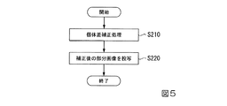
この一例における主プロジェクターであるプロジェクター10−1からコマンドを受信部141により受信した後、制御部16は、当該コマンドに基づいて個体差補正処理を実行する(ステップS210)。具体的には、制御部16は、コマンドに含まれる個体差を示す情報に基づいて画像処理部17を動作させ、個体差を無くすように部分画像P2の画質に関わる設定値を補正(変更)する。次に、制御部16は、画像処理部17が当該設定値を補正した部分画像P2を投写部151に投写させることによってスクリーンSCに表示させ(ステップS220)、処理を終了する。
After receiving a command from the projector 10-1 which is the main projector in this example by the receiving
なお、上記で説明した主プロジェクターと従プロジェクターとの間の主従関係は、張られたセッションが解除されるまで、すなわち主プロジェクターと従プロジェクターとの間の論理的な接続が切断されるまで保持される構成であってもよく、ユーザーから受け付けた操作に基づいて変更される構成であってもよい。 The master-slave relationship between the master projector and the slave projector described above is maintained until the extended session is released, that is, until the logical connection between the master projector and the slave projector is broken. It may be a configuration that is changed based on an operation received from the user.
また、上記で説明したコマンドは、タイリング投写において各プロジェクター10が投写する部分画像を、主プロジェクターが従プロジェクターに投写画像P0から生成(切り出し)させる命令であってもよい。この場合、主プロジェクターが投写画像P0をどのように分割するのかを示す情報を生成し、生成した情報を当該コマンドとともに各従プロジェクターに送信する。当該情報は、例えば、切り出すサイズや形を示す情報である。
Further, the command described above may be a command in which the main projector generates (cuts out) a partial image projected by each
以上説明したように、本実施形態に係るプロジェクター10は、第1画像(この一例において、部分画像P1)を投写部(この一例において、投写部151)により投写面(この一例において、スクリーンSC)に投写し、他のプロジェクター10から、他のプロジェクター10を識別する識別情報を受信し、受信した識別情報が示す他のプロジェクター10から、当該投写部による第1画像の投写とともに第2画像(この一例において、部分画像P2〜部分画像P4のそれぞれ)を投写面に投写させるプロジェクター10である従プロジェクターを選択する画面である選択画面(この一例において、選択画面G1)を生成し、生成した選択画面を表示部(この一例において、表示部15)により表示させ、表示部により表示させた選択画面に対する指示を受け付け、受け付けた指示によって選択された従プロジェクターにコマンドを送信する。これにより、プロジェクター10は、PCを用いることなく複数のプロジェクター10のうちのユーザーが所望するプロジェクター10にコマンドを実行させることができる。
As described above, in the
また、プロジェクター10は、従プロジェクターに実行させるコマンドを、自装置との接続が確立した従プロジェクターに送信する。これにより、プロジェクター10は、自装置との接続が確立した従プロジェクターにコマンドを実行させることができる。
Further, the
また、プロジェクター10は、生成した選択画面を投写部に投写させることにより投写面に表示させる。これにより、プロジェクター10は、投写面に表示させた選択画面に対する指示を受け付け、受け付けた指示に基づいて複数のプロジェクター10のうちのユーザーが所望するプロジェクター10にコマンドを実行させることができる。
Further, the
また、プロジェクター10は、生成した選択画面を表示装置(この一例において、表示装置152)に表示させる。これにより、プロジェクター10は、表示装置に表示させた選択画面に対する指示を受け付け、受け付けた指示に基づいて複数のプロジェクター10のうちのユーザーが所望するプロジェクター10にコマンドを実行させることができる。
Further, the
以上、この発明の実施形態を、図面を参照して詳述してきたが、具体的な構成はこの実施形態に限られるものではなく、この発明の要旨を逸脱しない限り、変更、置換、削除等されてもよい。 Although the embodiments of the present invention have been described in detail with reference to the drawings, the specific configuration is not limited to this embodiment, and changes, substitutions, deletions, etc. are made as long as the gist of the present invention is not deviated. May be done.
また、以上に説明した装置(例えば、プロジェクター10)における任意の構成部の機能を実現するためのプログラムを、コンピューター読み取り可能な記録媒体に記録し、そのプログラムをコンピューターシステムに読み込ませて実行するようにしてもよい。なお、ここでいう「コンピューターシステム」とは、OS(Operating System)や周辺機器等のハードウェアを含むものとする。また、「コンピューター読み取り可能な記録媒体」とは、フレキシブルディスク、光磁気ディスク、ROM、CD(Compact Disk)−ROM等の可搬媒体、コンピューターシステムに内蔵されるハードディスク等の記憶装置のことをいう。さらに「コンピューター読み取り可能な記録媒体」とは、インターネット等のネットワークや電話回線等の通信回線を介してプログラムが送信された場合のサーバーやクライアントとなるコンピューターシステム内部の揮発性メモリー(RAM)のように、一定時間プログラムを保持しているものも含むものとする。 Further, a program for realizing the function of an arbitrary component in the device (for example, the projector 10) described above is recorded on a computer-readable recording medium, and the program is read into a computer system and executed. It may be. The term "computer system" as used herein includes hardware such as an OS (Operating System) and peripheral devices. Further, the "computer-readable recording medium" refers to a portable medium such as a flexible disk, a magneto-optical disk, a ROM, a CD (Compact Disk) -ROM, or a storage device such as a hard disk built in a computer system. .. Furthermore, a "computer-readable recording medium" is a volatile memory (RAM) inside a computer system that serves as a server or client when a program is transmitted via a network such as the Internet or a communication line such as a telephone line. In addition, it shall include those that hold the program for a certain period of time.
また、上記のプログラムは、このプログラムを記憶装置等に格納したコンピューターシステムから、伝送媒体を介して、あるいは、伝送媒体中の伝送波により他のコンピューターシステムに伝送されてもよい。ここで、プログラムを伝送する「伝送媒体」は、インターネット等のネットワーク(通信網)や電話回線等の通信回線(通信線)のように情報を伝送する機能を有する媒体のことをいう。
また、上記のプログラムは、前述した機能の一部を実現するためのものであってもよい。さらに、上記のプログラムは、前述した機能をコンピューターシステムにすでに記録されているプログラムとの組み合わせで実現できるもの、いわゆる差分ファイル(差分プログラム)であってもよい。
Further, the above program may be transmitted from a computer system in which this program is stored in a storage device or the like to another computer system via a transmission medium or by a transmission wave in the transmission medium. Here, the "transmission medium" for transmitting a program refers to a medium having a function of transmitting information, such as a network (communication network) such as the Internet or a communication line (communication line) such as a telephone line.
Further, the above program may be for realizing a part of the above-mentioned functions. Further, the above program may be a so-called difference file (difference program) that can realize the above-mentioned functions in combination with a program already recorded in the computer system.
1…プロジェクターシステム、10、10−1〜10−4…プロジェクター、11…撮像部、12…記憶部、13…操作受付部、14…通信部、15…表示部、16…制御部、17…画像処理部、18…画像入力部、30…HUB、141…受信部、142…送信部、151…投写部、152…表示装置 1 ... Projector system, 10, 10-1 to 10-4 ... Projector, 11 ... Imaging unit, 12 ... Storage unit, 13 ... Operation reception unit, 14 ... Communication unit, 15 ... Display unit, 16 ... Control unit, 17 ... Image processing unit, 18 ... image input unit, 30 ... HUB, 141 ... receiver unit, 142 ... transmitter unit, 151 ... projection unit, 152 ... display device
Claims (10)
第1画像を投写面に投写する投写部と、
複数のプロジェクターの中からタイリング投写における主プロジェクターとして選択された場合、前記複数のプロジェクターのうち通信可能な1以上のプロジェクターのそれぞれを識別する識別情報を、前記1以上のプロジェクターのそれぞれから受信する受信部と、
前記受信部が受信した前記識別情報が示すプロジェクターの中から、前記第1画像とともにタイリング投写される画像を第2画像として前記投写面に投写させるプロジェクターをタイリング投写における従プロジェクターとして選択する画面である選択画面を生成する画面生成部と、
前記画面生成部が生成した前記選択画面を表示部により表示させる表示制御部と、
前記表示制御部が前記表示部により表示させた前記選択画面に対する指示を受け付ける指示受付部と、
前記指示受付部が受け付けた前記指示によって選択された前記従プロジェクターにコマンドを送信する送信部と、
を備え、
前記識別情報には、前記1以上のプロジェクターのそれぞれが設置された位置を示す情報が含まれており、
前記選択画面には、前記1以上のプロジェクターのそれぞれを示す情報とともに、前記1以上のプロジェクターのそれぞれが設置された位置を示す情報が含まれている、
プロジェクター。 It ’s a projector,
A projection unit that projects the first image onto the projection surface,
If selected as the main projector according tiling projection from a plurality of projectors, identification information for identifying, respectively that of the one or more projectors can communicate among the plurality of projectors, each of said one or more projectors The receiver that receives from
From the identification information received by the receiving unit is shown to the projector, the slave projector pulp projector in tiling projection is projected on the projection plane an image to be tiled projection together with the first image as a second image A screen generator that generates a selection screen, which is the screen to be selected as
A display control unit that displays the selection screen generated by the screen generation unit on the display unit,
An instruction receiving unit that receives an instruction for the selection screen displayed by the display control unit and the display unit.
A transmission unit that transmits a command to the slave projector selected by the instruction received by the instruction reception unit, and a transmission unit.
With
Wherein the identification information is respectively includes information indicating the installation position of the one or more projectors,
Wherein the selection screen, together with information indicating each of said one or more projectors, each of said one or more projector has includes information indicating the installation position,
projector.
請求項1に記載のプロジェクター。 The information indicating the position to which each is installed in the one or more projector includes information indicating the room where the slave projector is installed, it contains information indicating the position in the room,
The projector according to claim 1.
請求項1又は2に記載のプロジェクター。 The transmission unit transmits the command to be executed by the slave projector to the slave projector whose connection with the own device has been established.
The projector according to claim 1 or 2.
前記表示制御部は、前記画面生成部が生成した前記選択画面を前記投写部に投写させることにより前記投写面に表示させる、
請求項1から3のうちいずれか一項に記載のプロジェクター。 The display unit includes the projection unit.
The display control unit displays the selection screen generated by the screen generation unit on the projection surface by projecting it on the projection unit.
The projector according to any one of claims 1 to 3.
前記表示制御部は、前記画面生成部が生成した前記選択画面を前記表示装置に表示させる、
請求項1から4のうちいずれか一項に記載のプロジェクター。 The display unit includes a display device provided in the own device.
The display control unit causes the display device to display the selection screen generated by the screen generation unit.
The projector according to any one of claims 1 to 4.
前記制御方法は、
前記第1画像を前記投写部により前記投写面に投写し、
複数の他のプロジェクターのうち通信可能な1以上の前記他のプロジェクターのそれぞれから、前記他のプロジェクターを識別する識別情報を受信し、
受信した前記識別情報が示す前記他のプロジェクターの中から、前記第1画像とともにタイリング投写される画像を第2画像として前記投写面に投写させる前記他のプロジェクターをタイリング投写における従プロジェクターとして選択する画面である選択画面を生成し、
生成した前記選択画面を表示部により表示させ、
表示させた前記選択画面に対する指示を受け付け、
受け付けた前記指示によって選択された前記従プロジェクターにコマンドを送信し、
前記識別情報には、
前記1以上の前記他のプロジェクターのそれぞれが設置された位置を示す情報が含まれており、
前記選択画面には、
前記1以上の前記他のプロジェクターのそれぞれを示す情報とともに、前記1以上の前記他のプロジェクターのそれぞれが設置された位置を示す情報が含まれている、
制御方法。 It is a control method of a main projector including a projection unit that projects a first image on a projection surface.
The control method is
The first image is projected onto the projection surface by the projection unit, and the first image is projected onto the projection surface.
Identification information for identifying the other projector is received from each of the one or more communicable other projectors among the plurality of other projectors.
From the other projectors indicated by the received identification information, the other projector that projects the image to be tiling-projected together with the first image on the projection surface as the second image is selected as the secondary projector in the tiling projection. Generate a selection screen, which is the screen to be displayed,
Display the generated selection screen on the display unit, and display it.
Accepting instructions for the displayed selection screen,
Send a command to the slave projector selected by the received instruction,
The identification information includes
It contains information indicating the location where each of the one or more other projectors is installed.
On the selection screen,
In addition to information indicating each of the one or more other projectors, information indicating the position where each of the one or more other projectors is installed is included.
Control method.
請求項6に記載の制御方法。 The information indicating the position where each of the one or more projectors is installed includes information indicating a room in which the sub-projector is installed and information indicating a position in the room.
The control method according to claim 6.
請求項6又は7に記載の制御方法。 The command to be executed by the sub-projector is transmitted to the sub-projector for which a connection with the main projector has been established.
The control method according to claim 6 or 7.
生成した前記選択画面を前記投写部に投写させることにより前記投写面に表示させる、
請求項6から8のうちいずれか一項に記載の制御方法。 The display unit includes the projection unit.
By projecting the generated selection screen onto the projection unit, the screen is displayed on the projection surface.
The control method according to any one of claims 6 to 8.
生成した前記選択画面を前記表示装置に表示させる、
請求項6から9のうちいずれか一項に記載の制御方法。 The display unit includes a display device provided in the main projector.
Display the generated selection screen on the display device.
The control method according to any one of claims 6 to 9.
Priority Applications (1)
| Application Number | Priority Date | Filing Date | Title |
|---|---|---|---|
| JP2016008897A JP6759598B2 (en) | 2016-01-20 | 2016-01-20 | Projector and control method |
Applications Claiming Priority (1)
| Application Number | Priority Date | Filing Date | Title |
|---|---|---|---|
| JP2016008897A JP6759598B2 (en) | 2016-01-20 | 2016-01-20 | Projector and control method |
Publications (3)
| Publication Number | Publication Date |
|---|---|
| JP2017129731A JP2017129731A (en) | 2017-07-27 |
| JP2017129731A5 JP2017129731A5 (en) | 2019-02-21 |
| JP6759598B2 true JP6759598B2 (en) | 2020-09-23 |
Family
ID=59396645
Family Applications (1)
| Application Number | Title | Priority Date | Filing Date |
|---|---|---|---|
| JP2016008897A Active JP6759598B2 (en) | 2016-01-20 | 2016-01-20 | Projector and control method |
Country Status (1)
| Country | Link |
|---|---|
| JP (1) | JP6759598B2 (en) |
Families Citing this family (2)
| Publication number | Priority date | Publication date | Assignee | Title |
|---|---|---|---|---|
| JP7176190B2 (en) * | 2018-01-25 | 2022-11-22 | セイコーエプソン株式会社 | IMAGE DISPLAY DEVICE, IMAGE DISPLAY SYSTEM, AND IMAGE DISPLAY DEVICE CONTROL METHOD |
| JP7287408B2 (en) * | 2021-02-18 | 2023-06-06 | セイコーエプソン株式会社 | Display method, information processing device, and program |
-
2016
- 2016-01-20 JP JP2016008897A patent/JP6759598B2/en active Active
Also Published As
| Publication number | Publication date |
|---|---|
| JP2017129731A (en) | 2017-07-27 |
Similar Documents
| Publication | Publication Date | Title |
|---|---|---|
| US10373589B2 (en) | Display system, display device, controller, method of controlling display device, and program | |
| JP6459194B2 (en) | Projector and projected image control method | |
| US10768884B2 (en) | Communication apparatus, display apparatus, control method thereof, storage medium, and display system for configuring multi-display settings | |
| US20180011679A1 (en) | Information processing system, display processing apparatus, display processing method, and recording medium | |
| US20140211168A1 (en) | Image projection apparatus, control method, recording medium, and projection system | |
| US20160353096A1 (en) | Display device and image quality setting method | |
| US10009945B2 (en) | Communication device, communication device control method, and display system | |
| JP6759598B2 (en) | Projector and control method | |
| US10055065B2 (en) | Display system, projector, and control method for display system | |
| US20230070178A1 (en) | Control device, and control method | |
| US10560972B2 (en) | Information processing apparatus, and control method thereof | |
| US20190065130A1 (en) | Display device and method for controlling display device | |
| JP6766716B2 (en) | Information processing equipment, image display program, image display method and display system | |
| US11206379B2 (en) | Controlled apparatus and control method thereof | |
| US11099799B2 (en) | Method for controlling display device, display device, method for controlling display system, and display system | |
| JP6164335B2 (en) | Image formation data generation apparatus, image formation data generation system, image formation data generation method, and image formation data generation program | |
| JP2015014889A (en) | System, information processing method, information processing device, and program | |
| JP6992769B2 (en) | Display control method, display device and display system | |
| JP6249604B2 (en) | Projector, control method therefor, and image projection system | |
| US20230306102A1 (en) | Control method for information processing apparatus and non-transitory computer-readable storage medium storing program | |
| US20220130295A1 (en) | Display system and control method for display system | |
| US10996837B2 (en) | Electronic apparatus and method for controlling electronic apparatus | |
| JP2018191117A (en) | Information processing apparatus, information processing method and program | |
| JP6808927B2 (en) | Communication system, terminal equipment, and setting method | |
| JP6515578B2 (en) | INFORMATION PROCESSING TERMINAL, SEARCH SYSTEM, AND PROGRAM |
Legal Events
| Date | Code | Title | Description |
|---|---|---|---|
| RD03 | Notification of appointment of power of attorney |
Free format text: JAPANESE INTERMEDIATE CODE: A7423 Effective date: 20181026 |
|
| A521 | Written amendment |
Free format text: JAPANESE INTERMEDIATE CODE: A523 Effective date: 20190110 |
|
| A621 | Written request for application examination |
Free format text: JAPANESE INTERMEDIATE CODE: A621 Effective date: 20190110 |
|
| A977 | Report on retrieval |
Free format text: JAPANESE INTERMEDIATE CODE: A971007 Effective date: 20191028 |
|
| A131 | Notification of reasons for refusal |
Free format text: JAPANESE INTERMEDIATE CODE: A131 Effective date: 20191105 |
|
| A521 | Written amendment |
Free format text: JAPANESE INTERMEDIATE CODE: A523 Effective date: 20191226 |
|
| A131 | Notification of reasons for refusal |
Free format text: JAPANESE INTERMEDIATE CODE: A131 Effective date: 20200526 |
|
| A521 | Written amendment |
Free format text: JAPANESE INTERMEDIATE CODE: A523 Effective date: 20200720 |
|
| TRDD | Decision of grant or rejection written | ||
| A01 | Written decision to grant a patent or to grant a registration (utility model) |
Free format text: JAPANESE INTERMEDIATE CODE: A01 Effective date: 20200804 |
|
| A61 | First payment of annual fees (during grant procedure) |
Free format text: JAPANESE INTERMEDIATE CODE: A61 Effective date: 20200817 |
|
| R150 | Certificate of patent or registration of utility model |
Ref document number: 6759598 Country of ref document: JP Free format text: JAPANESE INTERMEDIATE CODE: R150 |