JP6758873B2 - Power control method for image forming equipment - Google Patents
Power control method for image forming equipment Download PDFInfo
- Publication number
- JP6758873B2 JP6758873B2 JP2016066082A JP2016066082A JP6758873B2 JP 6758873 B2 JP6758873 B2 JP 6758873B2 JP 2016066082 A JP2016066082 A JP 2016066082A JP 2016066082 A JP2016066082 A JP 2016066082A JP 6758873 B2 JP6758873 B2 JP 6758873B2
- Authority
- JP
- Japan
- Prior art keywords
- control means
- printing
- printing mechanism
- print control
- power
- Prior art date
- Legal status (The legal status is an assumption and is not a legal conclusion. Google has not performed a legal analysis and makes no representation as to the accuracy of the status listed.)
- Active
Links
Images


Classifications
-
- H—ELECTRICITY
- H04—ELECTRIC COMMUNICATION TECHNIQUE
- H04N—PICTORIAL COMMUNICATION, e.g. TELEVISION
- H04N1/00—Scanning, transmission or reproduction of documents or the like, e.g. facsimile transmission; Details thereof
- H04N1/00885—Power supply means, e.g. arrangements for the control of power supply to the apparatus or components thereof
- H04N1/00888—Control thereof
- H04N1/00891—Switching on or off, e.g. for saving power when not in use
-
- G—PHYSICS
- G03—PHOTOGRAPHY; CINEMATOGRAPHY; ANALOGOUS TECHNIQUES USING WAVES OTHER THAN OPTICAL WAVES; ELECTROGRAPHY; HOLOGRAPHY
- G03G—ELECTROGRAPHY; ELECTROPHOTOGRAPHY; MAGNETOGRAPHY
- G03G15/00—Apparatus for electrographic processes using a charge pattern
- G03G15/50—Machine control of apparatus for electrographic processes using a charge pattern, e.g. regulating differents parts of the machine, multimode copiers, microprocessor control
- G03G15/5004—Power supply control, e.g. power-saving mode, automatic power turn-off
-
- G—PHYSICS
- G03—PHOTOGRAPHY; CINEMATOGRAPHY; ANALOGOUS TECHNIQUES USING WAVES OTHER THAN OPTICAL WAVES; ELECTROGRAPHY; HOLOGRAPHY
- G03G—ELECTROGRAPHY; ELECTROPHOTOGRAPHY; MAGNETOGRAPHY
- G03G15/00—Apparatus for electrographic processes using a charge pattern
- G03G15/80—Details relating to power supplies, circuits boards, electrical connections
-
- H—ELECTRICITY
- H04—ELECTRIC COMMUNICATION TECHNIQUE
- H04N—PICTORIAL COMMUNICATION, e.g. TELEVISION
- H04N1/00—Scanning, transmission or reproduction of documents or the like, e.g. facsimile transmission; Details thereof
- H04N1/00885—Power supply means, e.g. arrangements for the control of power supply to the apparatus or components thereof
- H04N1/00901—Using different supplies or connection to an external supply
-
- H—ELECTRICITY
- H04—ELECTRIC COMMUNICATION TECHNIQUE
- H04N—PICTORIAL COMMUNICATION, e.g. TELEVISION
- H04N1/00—Scanning, transmission or reproduction of documents or the like, e.g. facsimile transmission; Details thereof
- H04N1/00885—Power supply means, e.g. arrangements for the control of power supply to the apparatus or components thereof
- H04N1/00904—Arrangements for supplying power to different circuits or for supplying power at different levels
-
- G—PHYSICS
- G03—PHOTOGRAPHY; CINEMATOGRAPHY; ANALOGOUS TECHNIQUES USING WAVES OTHER THAN OPTICAL WAVES; ELECTROGRAPHY; HOLOGRAPHY
- G03G—ELECTROGRAPHY; ELECTROPHOTOGRAPHY; MAGNETOGRAPHY
- G03G15/00—Apparatus for electrographic processes using a charge pattern
- G03G15/50—Machine control of apparatus for electrographic processes using a charge pattern, e.g. regulating differents parts of the machine, multimode copiers, microprocessor control
- G03G15/5075—Remote control machines, e.g. by a host
- G03G15/5083—Remote control machines, e.g. by a host for scheduling
-
- G—PHYSICS
- G03—PHOTOGRAPHY; CINEMATOGRAPHY; ANALOGOUS TECHNIQUES USING WAVES OTHER THAN OPTICAL WAVES; ELECTROGRAPHY; HOLOGRAPHY
- G03G—ELECTROGRAPHY; ELECTROPHOTOGRAPHY; MAGNETOGRAPHY
- G03G2215/00—Apparatus for electrophotographic processes
- G03G2215/00025—Machine control, e.g. regulating different parts of the machine
- G03G2215/00109—Remote control of apparatus, e.g. by a host
-
- H—ELECTRICITY
- H04—ELECTRIC COMMUNICATION TECHNIQUE
- H04N—PICTORIAL COMMUNICATION, e.g. TELEVISION
- H04N2201/00—Indexing scheme relating to scanning, transmission or reproduction of documents or the like, and to details thereof
- H04N2201/0077—Types of the still picture apparatus
- H04N2201/0094—Multifunctional device, i.e. a device capable of all of reading, reproducing, copying, facsimile transception, file transception
Description
本発明は、画像形成装置の電力制御に関し、詳細には、画像形成装置が備える印刷手段を停止状態に移行させる際に段階的に給電を停止する制御技術に関する。 The present invention relates to power control of an image forming apparatus, and more particularly to a control technique for gradually stopping power supply when the printing means included in the image forming apparatus is shifted to a stopped state.
MFP(Multi Function Peripheral)などの画像形成装置は、ユーザインタフェース(UI)や通信を制御するコントローラと、用紙の搬送や画像形成を担う印刷機構を備えている。このような印刷機構を有する画像形成装置において、プリントやコピーなどの処理が完了し、起動状態にある印刷機構を停止状態に移行する時は、コントローラに印刷機構に関する様々なデータをバックアップしてから、印刷機構への電力供給を停止するのが一般的である。ここで、バックアップの対象となるデータは、印刷機構に関係する各種消耗部材の使用状況、例えば電子写真方式の場合であれば定着ユニット(ドラム)の通紙枚数や通電時間といった時系列の変化をカウントした情報である。以下、このようなバックアップの対象となる印刷機構に関するデータを「カウンタデータ」と呼ぶこととする。MFPのような画像形成装置において、コントローラによって印刷機構を停止状態に移行させる際の従来の流れは概ね次の通りである。
1)まず、印刷機構からカウンタデータを取得してバックアップする。
2)次に、印刷機構に終了要求を送信し、ドラムのクールダウン、定着ユニットの離間、オゾン排出といった電力供給の停止に先立って必要な各種処理(以下、終了処理)を、印刷機構において実行させる。
3)印刷機構から終了処理の完了通知を受信するのを待って、印刷機構への電力供給を停止する。
An image forming apparatus such as an MFP (Multi Function Peripheral) is provided with a controller for controlling a user interface (UI) and communication, and a printing mechanism for transporting paper and forming an image. In an image forming apparatus having such a printing mechanism, when processing such as printing or copying is completed and the printing mechanism in the activated state is shifted to the stopped state, various data related to the printing mechanism are backed up in the controller. , It is common to stop the power supply to the printing mechanism. Here, the data to be backed up is the usage status of various consumable parts related to the printing mechanism, for example, in the case of the electrophotographic method, changes in time series such as the number of sheets to be passed through the fixing unit (drum) and the energization time This is the counted information. Hereinafter, the data related to the printing mechanism to be backed up will be referred to as "counter data". In an image forming apparatus such as an MFP, the conventional flow when the printing mechanism is shifted to the stopped state by the controller is generally as follows.
1) First, the counter data is acquired from the printing mechanism and backed up.
2) Next, a termination request is sent to the printing mechanism, and the printing mechanism executes various processes (hereinafter referred to as termination processes) necessary prior to stopping the power supply such as drum cool-down, separation of the fixing unit, and ozone emission. Let me.
3) Waiting for the completion notification of the end processing to be received from the printing mechanism, the power supply to the printing mechanism is stopped.
こうして印刷機構が停止状態に移行した後、印刷機構で管理されているカウンタデータにアプリケーションがアクセスするためには、印刷機構への電力供給を再開する必要がある。そのような再給電を避けるため、コントローラは、印刷機構からカウンタデータを吸い上げることで、アプリケーションから問い合わせを受けた時に、印刷機構に再給電しなくても応答できるようにしている。例えば、特許文献1は、メンテナンス状態に移行する前(すなわち、印刷機構への電力供給を停止する前)に、上記カウンタデータに相当するデータをキャッシュする手法が提案されている。 After the printing mechanism is stopped in this way, it is necessary to restart the power supply to the printing mechanism in order for the application to access the counter data managed by the printing mechanism. In order to avoid such re-powering, the controller sucks counter data from the printing mechanism so that when an inquiry is received from an application, the controller can respond without re-powering the printing mechanism. For example, Patent Document 1 proposes a method of caching data corresponding to the counter data before shifting to the maintenance state (that is, before stopping the power supply to the printing mechanism).
近年のMFPでは、その高速化・高機能化に伴い、印刷機構が管理するカウンタデータの設定項目数やデータサイズが増加傾向にある。そのため、印刷機構の終了処理に先立って行なわれる、以前は数秒で終わっていたカウンタデータのバックアップに数十秒もの時間が掛かるようになってきている。その結果、印刷機構を停止状態に移行させる場面において、印刷機構に給電している時間が延び、消費電力が増えるという状況が生じている。 In recent years, the number of setting items and data size of counter data managed by the printing mechanism are increasing with the increase in speed and functionality of MFPs. Therefore, it is taking several tens of seconds to back up the counter data, which was previously completed in several seconds, which is performed prior to the termination process of the printing mechanism. As a result, in the scene where the printing mechanism is shifted to the stopped state, the time for supplying power to the printing mechanism is extended, and the power consumption is increased.
本発明に係る印刷装置は、記録媒体上に画像を形成する印刷機構と、前記印刷機構を制御する印刷制御手段と、前記印刷機構及び前記印刷制御手段に対して電力の供給と停止を行う電力制御手段と、前記印刷制御手段と通信可能に接続される主制御手段と、を備え、前記主制御手段は、印刷処理の終了に従って、データ取得リクエストと終了リクエストとを前記印刷制御手段に送信し、前記電力制御手段は、前記終了リクエストに対する所定の応答に従って、前記印刷機構への電力供給を停止し、前記印刷制御手段はメモリを有し、前記データ取得リクエストに従って前記印刷機構に関するデータを取得して前記メモリに保持する、
ことを特徴とする。
The printing apparatus according to the present invention has a printing mechanism that forms an image on a recording medium, a printing control means that controls the printing mechanism, and a power supply that supplies and stops power to the printing mechanism and the printing control means. The main control means includes a control means and a main control means communicably connected to the print control means, and the main control means transmits a data acquisition request and an end request to the print control means according to the end of the print process. , The power control means stops power supply to the printing mechanism according to a predetermined response to the end request, the print control means has a memory, and acquires data about the printing mechanism according to the data acquisition request. And keep it in the memory
It is characterized by that.
本発明によれば、画像形成装置の印刷機構を起動状態から停止状態に移行させる場面において、消耗品等のカウンタデータのバックアップに支障を来たすことなく消費電力を低減することができる。 According to the present invention, in the scene where the printing mechanism of the image forming apparatus is changed from the started state to the stopped state, the power consumption can be reduced without hindering the backup of counter data such as consumables.
以下、添付の図面を参照して、本発明を実施する形態について説明する。なお、以下の実施例において示す構成は一例に過ぎず、本発明は図示された構成に限定されるものではない。 Hereinafter, embodiments of the present invention will be described with reference to the accompanying drawings. The configuration shown in the following examples is only an example, and the present invention is not limited to the illustrated configuration.
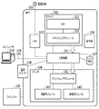
本実施例に係る画像形成装置として、以下では複数の機能を備えたMFPの場合を例に説明を行なうものとする。図1は、MFPのハードウェア構成の一例を示すブロック図である。図1に示すMFP100は、前述のコントローラに相当する主制御部101、スキャナ102、FAX103、プリンタ104、フィニッシャ105、操作部106、HDD107、電源スイッチ108で構成される。MFP100は、印刷機能、複写機能、送信機能、FAX機能、保存機能を備え、LAN109を介してコンピュータ110と接続されている。印刷機能は、コンピュータ110から受け取ったPDF(ページ記述言語)データを解析して用紙に印刷する機能である。複写機能は、原稿をスキャンして読み込んだ画像データを使用して用紙に印刷する機能である。送信機能は、原稿をスキャンして読み込んだ画像データを、LAN109を介してコンピュータ110に送信する機能である。FAX機能は、電話回線を通じてファクシミリ通信を行なう機能である。保存機能は、原稿をスキャンして読み込んだ画像データをHDD107に保存する機能である。なお、MFP100に接続するコンピュータ110の数は複数であってもよい。
As the image forming apparatus according to this embodiment, the case of an MFP having a plurality of functions will be described below as an example. FIG. 1 is a block diagram showing an example of the hardware configuration of the MFP. The MFP 100 shown in FIG. 1 includes a
主制御部101は、スキャナ102、FAX103、プリンタ104、フィニッシャ105などの各デバイスを統括的に制御し、各種ジョブを実行する。スキャナ102は、スキャン対象の原稿束を自動的に供給するADF(Auto Document Feeder)121と、原稿上の画像を光学的に読み取ってデジタル形式の画像データに変換するスキャンニングユニット122で構成される。ADF121から供給される原稿を光学的に読み取って生成された画像データは、主制御部101に送られる。FAX103は、電話回線を介して画像データを送受信する。プリンタ104は、前述の印刷機構を構成し、画像データに従って電子写真方式によって画像を紙等の記録媒体上に形成し出力する。ここでは、色材にトナーを使用する電子写真方式を例に説明するが、例えば色材にインクを使用するインクジェット方式など他の方式によって画像を形成するものであってもよい。プリンタ104は、用紙束から一枚ずつ逐次給紙可能な給紙ユニット142、給紙された用紙に画像を印刷するためのプリンティングユニット141、印刷後の用紙を排紙するための排紙ユニット143で構成される。フィニッシャ105も、前述の印刷機構の一部であり、排紙ユニット143から出力された印刷が施された用紙に対して、ソート、ステープル、パンチ、裁断、などの加工を施す。操作部106は、MFP100に対する各種の設定・指示をユーザから受け付けるためのハードキーや、処理状態を表示するためのディスプレイで構成される。ハードキーには、節電ボタン、コピーボタン、キャンセルボタン、リセットボタン、テンキー、ユーザモードキーなどが含まれる。なお、操作部106を、タッチパネル機能を有した例えばLCDディスプレイで構成し、当該LCDディスプレイを介して各種の設定・指示を受け付けてもよい。HDD107は、画像データや制御プログラム等を記憶する。電源スイッチ108は、MFP100の電源のオン/オフを切り替えるスイッチであり、主制御部101に接続されている。この電源スイッチ108がオンになっているとMFP100内の各部に対して電力が供給され、オフになっているとMFP100内の各部への電力供給が停止される。ただし、電源スイッチ108がオフになっても、即時に給電が停止するわけでなく、ソフトウェアやハードウェアの終了処理を待って各部への給電が停止される。また、その際も、電源スイッチ108をオンにするための回路など、一部については給電が維持される。
The
<主制御部の構成>
次に、主制御部101の詳細について説明する。図2は、主制御部101の内部構成並びに主制御部101とMFP100内の各デバイス等との関係を示すブロック図である。主制御部101は、メインボード200と、サブボード220から構成される。なお、図2は簡略図であり、例えばCPUに関するチップセット、バスブリッジ、クロックジェネレータ等の周辺ハードウェアは省略されている。
<Structure of main control unit>
Next, the details of the
メインボード200は、いわゆる汎用的なCPUシステムである。CPU201ボード全体を制御する中央演算処理装置である。ブートロム202は、ブートプログラムを格納する。メモリ203は、例えばDRAMといったCPU201がワークメモリとして使用するメモリである。バスコントローラ204は、サブボード220と接続され、外部バスとのブリッジ機能を担う。不揮発性メモリ205は、例えばフラッシュメモリといった電源が遮断された場合でも情報を保持可能なメモリである。ディスクコントローラ206は、HDD107や、半導体デバイスで構成された比較的小容量な記憶装置であるSSD等のフラッシュディスク207を制御する。USBコントローラ208は、USB(ユニバーサルシリアルバス)を介してMFP100に接続される周辺機器、例えばUSBメモリ209を制御する。
The
電源制御部210は、プリンタ104等の各デバイスからの割り込み信号や各デバイスに対する電力供給を、負荷に応じた系統毎に制御する。この電源制御部210は、CPU201、NIC(Network interface controller)211、リアルタイムクロック212、USBコントローラ208と接続されている。また、主制御部101の外部のデバイス(ソフトスイッチを持つ操作部106や、各種センサを持つスキャナ102、プリンタ104、フィニッシャ105)とも接続されている。
The
サブボード220は、メインボード200よりも小規模の汎用CPUシステムと、画像処理ハードウェアから構成される。具体的には、CPU221とそのワークメモリ(メモリ223)、バスコントローラ224、不揮発性メモリ225、2個のデバイスコントローラ226、画像処理用のイメージプロセッサ227を有する。主制御部101の外部に接続される、スキャナ102とプリンタ104は、それぞれデバイスコントローラ226を介して、画像データの受け渡しを行なう。FAX103は、CPU221によって直接制御される。
The
続いて、主制御部101の動作について、複写(コピー)処理を例に説明する。ユーザが操作部106からコピーを指示すると、CPU201がCPU221を介してスキャナ102に対し画像読み取り命令を送る。画像読み取り命令を受け取ったスキャナ102は、原稿をスキャンして得た画像データを、デバイスコントローラ226を介してイメージプロセッサ227に入力する。イメージプロセッサ227では、CPU221を介してメモリ223に画像データをDMA転送し、画像データを一時保存する。CPU201は、画像データがメモリ223に一定量蓄積されたことが確認できると、CPU221を介してプリンタ104に印刷指示を出す。CPU221は、イメージプロセッサ227に対し、処理対象画像データのメモリ223上のアドレスを教える。メモリ223上の画像データは、プリンタ104からの同期信号に従って、イメージプロセッサ227とデバイスコントローラ226を介してプリンタ104に送信される。プリンタ104は、画像データに従った画像を用紙に形成して出力する。なお、複数部印刷の場合は、CPU201はメモリ223上の画像データをHDD107に保存し、2部目以降はHDD107やメモリ223からプリンタ104に対し画像データを送る。
Subsequently, the operation of the
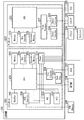
<電源構成>
図3は、MFP100の電源構成を示すブロック図である。以下、本発明に関わる部分を中心に、MFP100において電源がどのように供給されるのかを説明する。まず、電源制御部210には、電源301からの第1の電源ライン(電源ラインJ)経由で常時電力が供給されている。僅かな電力消費にとどまるため、電源オフ時にはこの電源制御部210だけに通電され、電力制御が行われる。
<Power supply configuration>
FIG. 3 is a block diagram showing a power supply configuration of the
電源制御部210は、予め所定の動作を実行するようプログラムされている。具体的には以下のとおりである。まず、第1の電源制御信号(IO信号V_ON)によって、リレースイッチ302が切り替わり、電源301からの第2の電源ライン(電源ラインV)経由での主制御部101への給電が制御される。また、CPU201により複数のタイマ値が設定され、タイマ起動時にはCPU201によって設定された動作を実行する。
The power
また、第2の電源制御信号(IO信号P_ON)によって、リレースイッチ303が切り替わる。その結果、電源301からの第3の電源ライン(電源ラインP)経由で、印刷機構のうち相対的に負荷の低い側の系統(以下、「ロジック系統」)に属するモジュールであるプリンタ制御部320への給電が制御される。プリンタ制御部320は、CPU321とメモリ322を有し、例えば現像や通紙のタイミングといった印刷に関わる様々な制御を行う。
Further, the
さらに、第2の電源制御信号のサブ信号(IO信号Q_ON)によって、リレースイッチ304が切り替わる。その結果、電源301からの第3の電源ラインのサブライン(電源ラインQ)経由で、印刷機構のうち相対的に負荷の高い側の系統(以下、「負荷系統」)に属するモジュールである、プリンティングユニット141等への給電が制御される。図3では、プリンティングユニット141における、CMYKの各トナーに対応する定着ユニット331〜334とFAN335が図示されている。図3では省略されているが、モータ等の駆動系の部品を備える他のモジュール、すなわち、給紙ユニット142や排紙ユニット143、さらにはフィニッシャ105にも電源ラインQを通じて必要な電力が供給される。なお、電源ラインQは、電源ラインPのサブラインである必要はなく、電源301から直接引くことも可能である。また、リレースイッチ304は、電源制御部210から制御する構成となっているが、プリンタ制御部320内のCPU321から制御するように構成してもよい。
Further, the
また、電源制御部210は、CPU201の指示によって、所定のIO信号を出す。対象となるIO信号の一つは、プリンタ制御部320内のCPU321へ接続されたDCON_LIVEWAKE信号である。このDCON_LIVEWAKE信号がアサートされた状態でプリンタ104の電源が投入されると、プリンタ104は一定の電力消費を伴う特定動作を行うことなく静かに復帰する。この特定動作には、例えば、モータ、ローラ、ポリゴンなどの回転動作や、定着ユニット331〜334の温調やFAN335による排熱処理などが含まれる。ここでの説明は省略するが、スキャナ102についてもプリンタ104と同様の電源制御が行われる。
Further, the power
なお、上述したブロック単位での給電は、例えばリレースイッチを2系統で構成し、スリープモードへの移行時には電源をオフするブロックに繋がるリレースイッチのみをオフとし、他方のリレースイッチについてはオン状態を維持するといった手法で実現できる。そして、シャットダウンする際は、両系統のリレースイッチをオフにすればよい。その場合には、電源制御信号は二値ではなく、通電状態に応じた多値の制御信号となる。以下、動作モードに応じた電源制御の一例を示す。電源制御部210は、第3の電源制御信号(IO信号N_ON)によって、リレースイッチ305を切り替え、電源301からの第3の電源ライン(電源ラインN)経由で、NIC211への給電を制御する。こうして主制御部101の内、NIC211だけが個別に給電される。電源ラインNは、他の非常夜電源と異なり、通常モード時だけでなく、スリープモード時にも給電され、ネットワーク起床を可能にする。また、シャットダウンの時はWake On LANなどの設定が有効でない限りは、給電しない。リレースイッチ305を経由した電源ラインNは、基本的には常に給電状態である。
For the above-mentioned power supply in block units, for example, two relay switches are configured, and when the mode shifts to sleep mode, only the relay switch connected to the block that turns off the power is turned off, and the other relay switch is turned on. It can be realized by a method such as maintaining. Then, when shutting down, the relay switches of both systems may be turned off. In that case, the power supply control signal is not a binary control signal but a multi-valued control signal according to the energized state. The following is an example of power supply control according to the operation mode. The power
ここで、本発明の課題について再確認しておく。例えば、定着ユニット(ドラム)331〜334についてのカウンタデータをバックアップする際、これまでは、ドラムに付随して設けられた不揮発性メモリ(不図示)から直接取得する必要があった。そのため、プリンティングユニット141が属する負荷系統への通電が必要だった。しかし、近年は、ロジック系統に属するモジュール内、すなわち、プリンタ制御部320内のメモリ322にカウンタデータをキャッシュすることで、負荷系統への通電をしなくても、カウンタデータを取得できるようになってきている。つまり、主制御部101のCPU201からのデータ取得要求に対し、プリンタ制御部320のCPU321は、ドラムに付随する不揮発性メモリから実際のデータを取得せずに、メモリ322にキャッシュされたデータを返すようになっている。
Here, the subject of the present invention is reconfirmed. For example, when backing up the counter data for the fixing unit (drum) 331 to 334, it has been necessary to directly acquire the counter data from the non-volatile memory (not shown) provided attached to the drum. Therefore, it was necessary to energize the load system to which the
一方、近年は節電機能が進化し、ユーザがMFP100を使用するときに、その場面で利用する機能に対応したデバイスやモジュールのみに通電するようになっている。その結果、MFP100における通電状態が複雑化してきている。つまり、主制御部101のCPU201からのカウンタデータの取得要求時に、負荷系統のデバイスに通電していない、或いは、通電はしていても音を伴うモジュールの初期化処理は行わないなど、デバイスやモジュール単位で様々な通電状態があり得る。そこで、高負荷のデバイスに通電しない状態や、動作時に音を発生するモジュールに通電しない状態の時にも必要なデータが取得できるよう、ロジック系統のモジュール内に、負荷系統に属するデバイスやモジュールの情報も保存するようになってきた。その結果、カウンタデータの吸い上げ前に、負荷系統のデバイスやモジュールへの給電を停止しても問題が生じないようになってきている。なお、カウンタデータの値が更新される都度、ロジック系統のモジュールであるプリンタ制御部320のメモリ322から、主制御部101のメモリ203にカウンタデータを送って保存することも考えられるがそのような制御は行われていない。それは、主制御部101とプリンタ制御部320との間では画像データのやり取りが行われるので、カウンタデータが更新されるたびに当該カウンタデータの送受信が発生すると、印刷パフォーマンスに影響するためである。
On the other hand, in recent years, the power saving function has evolved, and when the user uses the
しかしながら、MFP100の高速化・高機能化に伴い、カウンタデータの項目数やデータサイズが増加傾向にあり、ロジック系統のモジュール内に保存するためのバックアップにこれまでよりも多くの時間が掛かるようになってきた。その結果、印刷機構を起動状態から停止状態に移行させる場面において、相対的に負荷の高い負荷系統に属するプリンティングユニット141等に給電している時間が延び、消費電力が増えるという状況が生まれている。本発明はこの点に着目したもので、印刷機構を停止状態に移行させる際に、カウンタデータのバックアップに支障を来たすことなく、相対的に高負荷の系統への給電を早期に停止して、消費電力を低減することを目的とするものである。
However, as the speed and functionality of the MFP100 increase, the number of counter data items and data size tend to increase, and it will take more time than before to back up to save in the module of the logic system. It has become. As a result, in the scene where the printing mechanism is changed from the started state to the stopped state, the time for supplying power to the
次に、本実施例の特徴である、印刷機構を起動状態から停止状態に移行させる際の制御について説明する。図4は、停止状態移行時の制御の流れを示すフローチャートである。この一連の処理は、主制御部101内のCPU201が、HDD107等に格納されている所定のプログラムをメモリ203にロードし、実行することで実現される。図4に示すフローでは、印刷機構を起動状態から停止状態に移行させる際に、負荷の異なる系統別に段階的に電力供給を停止していく点が従来と異なる。この停止状態移行時の制御は、MFP100全体をシャットダウンするときや、各機能に対応するデバイスのうち使用対象デバイスのみに給電する部分給電の実施時において、印刷処理の終了と共に印刷機構を停止状態に移行させる際に適用される。典型的には、印刷ジョブの終了など、印刷機構を起動状態から停止状態に移行させるための開始条件が整ったことを検知することで、図4のフローは実行される。以下、図4のフローチャートに沿って、本実施例に係る停止状態移行時の制御について説明する。図4のフローチャートでは、負荷に応じて区分される複数の系統のうち相対的に高負荷の系統への給電停止を行うためのステップ401〜403の各処理と、カウンタデータのバックアップのためのステップ404〜405の各処理とが、並列で実行される。
Next, the control when shifting the printing mechanism from the started state to the stopped state, which is a feature of this embodiment, will be described. FIG. 4 is a flowchart showing a control flow at the time of transition to the stopped state. This series of processes is realized by the
ステップ401では、CPU201が、前述の終了要求をプリンタ制御部320に送信する。終了要求を受け取ったプリンタ制御部320は、給電停止に先立って要求される終了処理、具体的には、定着ユニット331〜334の離間や、フィニッシャ105のリフタを下すといった、モータやギアを使った駆動系のリセットを含む処理を行う。この終了処理が完了するとプリンタ制御部320は、終了処理の完了を示すack信号をCPU201に返す。なお、プリンタ制御部320が終了要求を受信した時点で、負荷系統のリレースイッチ304がオンになっておらず電源が入っていない場合もある。この場合において、定着ユニットの離間処理などが必要であれば、リレースイッチ304を一旦オンにした上で、終了処理を行なえばよい。
In step 401, the
ステップ402では、CPU201が、ack信号をプリンタ制御部320から受信したかどうかを判定する。ack信号を受信していた場合は、ステップ403に進む。一方、ack信号を受信していない場合は、一定時間の経過を待って再度判定を行い、ack信号を受信するまで監視を継続する。
In
ステップ403では、CPU201が、負荷系統に属するデバイス・モジュールへの電力供給の停止を電源制御部210に指示する。当該指示を受けて電源制御部210は、IO信号Q_ONによってリレースイッチ304をオンからオフに切り替え、電源ラインQを遮断する。これにより、相対的に負荷の高い、プリンティングユニット141やフィニッシャ105などへの電力供給が停止する。
In
ここまでが印刷機構のうち相対的に負荷の高い負荷系統への給電停止を早期に実施するための処理である。本実施例ではこの処理と並行して、以下のステップ404及び405で示すバックアップのための各処理が実行される。
The above is the process for early stopping the power supply to the load system with a relatively high load in the printing mechanism. In this embodiment, in parallel with this process, each process for backup shown in the following
ステップ404では、CPU201が、プリンタ制御部320に対し、カウンタデータの取得要求を送信する。取得要求を受け取ったプリンタ制御部320は、当該取得要求に係る項目(例えばドラムの通紙枚数)の最新の値を取得してメモリ322内に格納し、格納が完了するとack信号をCPU201に返す。
In
ステップ405では、CPU201が、ack信号をプリンタ制御部320から受信したかどうかを判定する。ack信号を受信していた場合は、ステップ406に進む。一方、ack信号を受信していない場合は、一定時間の経過を待って再度判定を行い、ack信号を受信するまで監視を継続する。
In step 405, the
ステップ406では、CPU201が、負荷系統への電力供給停止と、カウンタデータのバックアップの両方が完了したかどうかを判定する。両方が完了していた場合は、ステップ407に進む。一方、両方の完了が確認できない場合は、一定時間の経過を待って再度判定を行い、両方の完了が確認できるまで監視を継続する。
In step 406, the
ステップ407では、CPU201が、ロジック系統に属するデバイスへの電力供給の停止を電源制御部210に指示する。当該指示を受けて電源制御部210は、IO信号P_ONによってリレースイッチ303をオンからオフに切り替え、電源ラインPを遮断する。こうして、バックアップが完了した後に、相対的に負荷の低いロジック系統のモジュールであるプリンタ制御部320への電力供給が停止する。
In step 407, the
以上が、MFP100の印刷機構を起動状態から停止状態に移行させる際の制御の内容である。
The above is the content of the control when shifting the printing mechanism of the
なお、本実施例では、負荷系統への給電停止のための各処理(ステップ401〜403)と、カウンタデータのバックアップのための各処理(ステップ404〜405)とを並列で行っているが、これに限定されるものではない。例えば、負荷系統への給電停止のための各処理が完了した後で、カウンタデータのバックアップのための各処理を実行するにようにしてもよい。
In this embodiment, each process for stopping the power supply to the load system (steps 401 to 403) and each process for backing up the counter data (
また、本実施例では、負荷に応じた系統を、負荷の高い側の負荷系統と負荷の低い側のロジック系統の2種類に分けているが、これに限定されず、例えば高・中・低のように3段階の系統に分けてもよい。要は、印刷機構のうち、消費電力が相対的に高い系統への給電停止を、カウンタデータのバックアップを担うモジュールが属する系統に先行して行なうような構成であればよい。 Further, in this embodiment, the system according to the load is divided into two types, a load system on the high load side and a logic system on the low load side, but the system is not limited to this, for example, high, medium, and low. It may be divided into three stages such as. In short, the printing mechanism may be configured so that power supply to a system having relatively high power consumption is stopped prior to the system to which the module responsible for backing up the counter data belongs.
以上のとおり本実施例によれば、画像形成装置の印刷機構を停止状態に移行させる場面において、相対的に高負荷の負荷系統への電源遮断と、カウンタデータのバックアップとが同時並行でなされ、その後に低負荷の系統(ロジック系統)への電源遮断がなされる。これにより、負荷系統への給電を停止した後にロジック系統への給電を停止するという順序性が保証され、その結果、消耗品等のカウンタデータのバックアップに支障を来たすことなく消費電力を減らすことができる。 As described above, according to the present embodiment, in the scene where the printing mechanism of the image forming apparatus is shifted to the stopped state, the power is cut off to the load system having a relatively high load and the counter data is backed up at the same time. After that, the power supply to the low-load system (logic system) is cut off. This guarantees the order in which the power supply to the load system is stopped and then the power supply to the logic system is stopped, and as a result, the power consumption can be reduced without interfering with the backup of counter data such as consumables. it can.
(その他の実施例)
本発明は、上述の実施形態の1以上の機能を実現するプログラムを、ネットワーク又は記憶媒体を介してシステム又は装置に供給し、そのシステム又は装置のコンピュータにおける1つ以上のプロセッサがプログラムを読出し実行する処理でも実現可能である。また、1以上の機能を実現する回路(例えば、ASIC)によっても実現可能である。
(Other Examples)
The present invention supplies a program that realizes one or more functions of the above-described embodiment to a system or device via a network or storage medium, and one or more processors in the computer of the system or device reads and executes the program. It can also be realized by the processing to be performed. It can also be realized by a circuit (for example, ASIC) that realizes one or more functions.
Claims (29)
前記印刷機構を制御する印刷制御手段と、
前記印刷機構及び前記印刷制御手段に対して電力の供給と停止を行う電力制御手段と、前記印刷制御手段と通信可能に接続される主制御手段と、
を備え、
前記主制御手段は、印刷処理の終了に従って、データ取得リクエストと終了リクエストとを前記印刷制御手段に送信し、
前記電力制御手段は、前記終了リクエストに対する所定の応答に従って、前記印刷機構への電力供給を停止し、
前記印刷制御手段はメモリを有し、前記データ取得リクエストに従って前記印刷機構に関するデータを取得して前記メモリに保持する、
ことを特徴とする印刷装置。 A printing mechanism that forms an image on a recording medium,
A print control means for controlling the printing mechanism and
A power control means for supplying and stopping electric power to the printing mechanism and the print control means, and a main control means communicably connected to the print control means.
With
The main control means transmits a data acquisition request and an end request to the print control means according to the end of the print process .
The power control means stops the power supply to the printing mechanism according to a predetermined response to the termination request.
The print control means has a memory, and acquires data related to the printing mechanism according to the data acquisition request and holds the data in the memory.
A printing device characterized by that.
前記電力制御手段は、前記リセットする処理が完了した後に、前記印刷制御手段への電力供給を停止することを特徴とする請求項1乃至4のいずれか1項に記載の印刷装置。 The main control means instructs the printing mechanism to execute a process of resetting the drive system related to the printing process.
The printing apparatus according to any one of claims 1 to 4, wherein the power control means stops supplying power to the print control means after the resetting process is completed.
前記印刷制御手段は、前記終了リクエストに従って、前記定着ユニットを離間させる処理を行う、
ことを特徴とする請求項1乃至3のいずれか1項に記載の印刷装置。 The printing mechanism includes a fixing unit.
The print control means performs a process of separating the fixing unit according to the end request .
The printing apparatus according to any one of claims 1 to 3, wherein the printing apparatus is characterized by the above.
前記印刷制御手段は、前記終了リクエストに従って、前記リフタを下す処理を行う、
ことを特徴とする請求項1乃至3のいずれか1項に記載の印刷装置。 The printing mechanism includes a finisher lifter.
The print control means performs a process of lowering the lifter in accordance with the end request .
The printing apparatus according to any one of claims 1 to 3, wherein the printing apparatus is characterized by the above.
前記印刷制御手段は、前記終了リクエストに従って、前記モーターをリセットする処理を行う、
ことを特徴とする請求項1乃至3のいずれか1項に記載の印刷装置。 The printing mechanism includes a motor.
The print control means performs a process of resetting the motor in accordance with the end request .
The printing apparatus according to any one of claims 1 to 3, wherein the printing apparatus is characterized by the above.
データを保持するためのメモリを有し、前記印刷機構を制御する印刷制御手段と、前記印刷機構及び前記印刷制御手段に対して電力の供給と停止を行う電力制御手段と、前記印刷制御手段と通信可能に接続される主制御手段と、
を備え、
前記主制御手段は、印刷処理の終了に従って、前記印刷制御手段において前記印刷機構に関するデータを取得して前記メモリに保持させ、
前記電力制御手段は、前記取得の完了を待つことなく、前記印刷機構への電力供給を停止する、
ことを特徴とする印刷装置。 A printing mechanism that forms an image on a recording medium,
A print control means that has a memory for holding data and controls the printing mechanism, a power control means that supplies and stops power to the printing mechanism and the print control means, and the print control means. The main control means connected so that it can communicate,
With
Upon completion of the printing process , the main control means acquires data related to the printing mechanism in the print control means and holds the data in the memory.
The power control means stops the power supply to the printing mechanism without waiting for the completion of the acquisition.
A printing device characterized by that.
前記電力制御手段は、前記リセットする処理が完了した後に、前記印刷制御手段への電力供給を停止する、
ことを特徴とする請求項10乃至13のいずれか1項に記載の印刷装置。 The main control means instructs the printing mechanism to execute a process of resetting the drive system related to the printing process.
The power control means stops the power supply to the print control means after the reset process is completed.
The printing apparatus according to any one of claims 10 to 13 .
前記印刷制御手段は、前記電力制御手段による前記印刷機構への電力供給の停止に先立って前記定着ユニットを離間させる処理を行う、
ことを特徴とする請求項10乃至12のいずれか1項に記載の印刷装置。 The printing mechanism includes a fixing unit.
The print control means performs a process of separating the fixing unit prior to stopping the power supply to the printing mechanism by the power control means.
The printing apparatus according to any one of claims 10 to 12 , characterized in that.
前記印刷制御手段は、前記電力制御手段による前記印刷機構への電力供給の停止に先立って前記リフタを下す処理を行う、
ことを特徴とする請求項10乃至12のいずれか1項に記載の印刷装置。 The printing mechanism includes a finisher lifter.
The print control means performs a process of lowering the lifter prior to stopping the power supply to the printing mechanism by the power control means.
The printing apparatus according to any one of claims 10 to 12 , characterized in that.
前記印刷制御手段は、前記電力制御手段による前記印刷機構への電力供給の停止に先立って前記モーターをリセットする処理を行う、
ことを特徴とする請求項10乃至12のいずれか1項に記載の印刷装置。 The printing mechanism includes a motor.
The print control means performs a process of resetting the motor prior to stopping the power supply to the printing mechanism by the power control means.
The printing apparatus according to any one of claims 10 to 12 , characterized in that.
前記印刷機構を制御する印刷制御手段と、
前記印刷機構及び前記印刷制御手段に対して電力の供給と停止を行う電力制御手段と、前記印刷制御手段と通信可能に接続される主制御手段と、
を備え、
前記主制御手段は、
印刷処理の終了に従って、データ取得リクエストを前記印刷制御手段に送信し、
前記印刷制御手段はメモリを有し、前記データ取得リクエストに従って前記印刷機構に関するデータを取得して前記メモリに保持し、
所定の条件に従って前記印刷制御手段が保持する前記印刷機構に関するデータを取得し、
前記電力制御手段は、前記取得の完了を待つことなく、前記印刷制御手段に終了リクエストを送信し、
前記電力制御手段は、前記終了リクエストに対する所定の応答に従って、前記印刷機構への電力供給を停止する、
ことを特徴とする印刷装置。 A printing mechanism that forms an image on a recording medium,
A printing control means for controlling the printing mechanism and
A power control means for supplying and stopping electric power to the printing mechanism and the print control means, and a main control means communicably connected to the print control means.
With
The main control means
Upon completion of the print process, a data acquisition request is transmitted to the print control means.
The print control means has a memory, acquires data related to the printing mechanism in accordance with the data acquisition request, and holds the data in the memory.
Acquire data on the printing mechanism held by the printing control means according to a predetermined condition, and obtain data.
The power control means sends an end request to the print control means without waiting for the completion of the acquisition.
The power control means stops the power supply to the printing mechanism according to a predetermined response to the termination request.
A printing device characterized by that.
前記電力制御手段は、前記リセットする処理が完了した後に、前記印刷制御手段への電力供給を停止する、
ことを特徴とする請求項19乃至22のいずれか1項に記載の印刷装置。 The main control means instructs the printing mechanism to execute a process of resetting the drive system related to the printing process.
The power control means stops the power supply to the print control means after the reset process is completed.
The printing apparatus according to any one of claims 19 to 22 , wherein the printing apparatus is characterized by the above.
前記印刷制御手段は、前記終了リクエストに従って、前記定着ユニットを離間させる処理を行う、
ことを特徴とする請求項19乃至21のいずれか1項に記載の印刷装置。 The printing mechanism includes a fixing unit.
The print control means performs a process of separating the fixing unit according to the end request .
The printing apparatus according to any one of claims 19 to 21 , characterized in that.
前記印刷制御手段は、前記終了リクエストに従って、前記リフタを下す処理を行う、
ことを特徴とする請求項19乃至21のいずれか1項に記載の印刷装置。 The printing mechanism includes a finisher lifter.
The print control means performs a process of lowering the lifter in accordance with the end request .
The printing apparatus according to any one of claims 19 to 21 , characterized in that.
前記印刷制御手段は、前記終了リクエストに従って、前記モーターをリセットする処理を行う、
ことを特徴とする請求項19乃至21のいずれか1項に記載の印刷装置。 The printing mechanism includes a motor.
The print control means performs a process of resetting the motor in accordance with the end request .
The printing apparatus according to any one of claims 19 to 21 , characterized in that.
前記印刷装置は、
記録媒体上に画像を形成力する印刷機構と、
データを保持するためのメモリを有し、前記印刷機構を制御する印刷制御手段と、前記印刷機構及び前記印刷制御手段に対して電力の供給と停止を行う電力制御手段と、
前記印刷制御手段と通信可能に接続される主制御手段と、
を備え、
前記主制御手段によって、印刷処理の終了に従って、データ取得リクエストと終了リクエストとを、前記印刷制御手段に送信するステップと、
前記電力制御手段によって、前記終了リクエストに対する所定の応答に従って、前記印刷機構への電力供給を停止するステップと、
前記印刷制御手段が、前記データ取得リクエストに従って前記印刷機構に関するデータを取得して前記メモリに保持するステップと、
を含むことを特徴とする制御方法。 It is a control method of the printing device.
The printing device is
A printing mechanism that forms an image on a recording medium,
A print control means that has a memory for holding data and controls the printing mechanism, and a power control means that supplies and stops power to the printing mechanism and the print control means.
A main control means that is communicably connected to the print control means,
With
A step of transmitting a data acquisition request and an end request to the print control means according to the end of the print process by the main control means.
A step of stopping the power supply to the printing mechanism according to a predetermined response to the termination request by the power control means.
A step in which the print control means acquires data related to the printing mechanism in accordance with the data acquisition request and holds the data in the memory.
A control method characterized by including.
Priority Applications (2)
| Application Number | Priority Date | Filing Date | Title |
|---|---|---|---|
| JP2016066082A JP6758873B2 (en) | 2016-03-29 | 2016-03-29 | Power control method for image forming equipment |
| US15/458,563 US10455103B2 (en) | 2016-03-29 | 2017-03-14 | Power control method of printing apparatus |
Applications Claiming Priority (1)
| Application Number | Priority Date | Filing Date | Title |
|---|---|---|---|
| JP2016066082A JP6758873B2 (en) | 2016-03-29 | 2016-03-29 | Power control method for image forming equipment |
Publications (3)
| Publication Number | Publication Date |
|---|---|
| JP2017177456A JP2017177456A (en) | 2017-10-05 |
| JP2017177456A5 JP2017177456A5 (en) | 2019-04-25 |
| JP6758873B2 true JP6758873B2 (en) | 2020-09-23 |
Family
ID=59962136
Family Applications (1)
| Application Number | Title | Priority Date | Filing Date |
|---|---|---|---|
| JP2016066082A Active JP6758873B2 (en) | 2016-03-29 | 2016-03-29 | Power control method for image forming equipment |
Country Status (2)
| Country | Link |
|---|---|
| US (1) | US10455103B2 (en) |
| JP (1) | JP6758873B2 (en) |
Families Citing this family (3)
| Publication number | Priority date | Publication date | Assignee | Title |
|---|---|---|---|---|
| US11106270B2 (en) * | 2017-01-31 | 2021-08-31 | Hewlett-Packard Development Company, L.P. | Parallel/serial operational sequencing |
| JP7158986B2 (en) * | 2018-10-09 | 2022-10-24 | キヤノン株式会社 | Image processing apparatus capable of acquiring counter information of functional unit and control method thereof |
| CN114270797A (en) * | 2020-07-31 | 2022-04-01 | 鸿富锦精密工业(武汉)有限公司 | Power switching device and image processing device with same |
Family Cites Families (13)
| Publication number | Priority date | Publication date | Assignee | Title |
|---|---|---|---|---|
| JP3610116B2 (en) * | 1994-04-14 | 2005-01-12 | キヤノン株式会社 | Image recording device |
| JP2002123049A (en) * | 2000-10-16 | 2002-04-26 | Canon Inc | Sheet processor, method for mounting the same, and image forming device |
| US7107006B1 (en) * | 2000-10-16 | 2006-09-12 | Canon Kabushi Kaisha | Sheet treating apparatus, method of mounting sheet treating apparatus, and image forming apparatus |
| JP2004026325A (en) * | 2002-06-21 | 2004-01-29 | Canon Inc | Sheet processing device and image forming device provided with the same |
| KR100476957B1 (en) * | 2002-07-23 | 2005-03-16 | 삼성전자주식회사 | Power supply controlling device of electronic equipment |
| JP4300824B2 (en) * | 2003-02-28 | 2009-07-22 | 富士ゼロックス株式会社 | Image forming apparatus |
| JP4547860B2 (en) * | 2003-03-12 | 2010-09-22 | 富士ゼロックス株式会社 | Power supply |
| JP4468026B2 (en) * | 2004-03-16 | 2010-05-26 | 株式会社沖データ | Image forming apparatus |
| JP2009119823A (en) * | 2007-11-19 | 2009-06-04 | Seiko Epson Corp | Control method of image formation device and this device |
| JP6039362B2 (en) * | 2012-10-25 | 2016-12-07 | キヤノン株式会社 | Image forming apparatus, control method therefor, and program |
| JP2014226884A (en) * | 2013-05-24 | 2014-12-08 | 株式会社リコー | Image forming apparatus and power supply control method |
| JP6207261B2 (en) * | 2013-06-28 | 2017-10-04 | キヤノン株式会社 | Image forming apparatus |
| JP2015170002A (en) * | 2014-03-05 | 2015-09-28 | キヤノン株式会社 | Image forming apparatus, control method of image forming apparatus, and program |
-
2016
- 2016-03-29 JP JP2016066082A patent/JP6758873B2/en active Active
-
2017
- 2017-03-14 US US15/458,563 patent/US10455103B2/en active Active
Also Published As
| Publication number | Publication date |
|---|---|
| US20170289376A1 (en) | 2017-10-05 |
| JP2017177456A (en) | 2017-10-05 |
| US10455103B2 (en) | 2019-10-22 |
Similar Documents
| Publication | Publication Date | Title |
|---|---|---|
| JP5064995B2 (en) | Data processing apparatus, data processing method, and program | |
| US10110764B2 (en) | Image forming apparatus that shifts into different power saving states and control method thereof | |
| US10484563B2 (en) | Image forming apparatus, and method for controlling image forming apparatus | |
| JP5341630B2 (en) | Data processing apparatus and data processing method | |
| US8922805B2 (en) | Image processing apparatus having updatable firmware, method for controlling image processing apparatus, and program | |
| US10447878B2 (en) | Image forming apparatus, method for controlling image forming apparatus, and storage medium | |
| JP6758873B2 (en) | Power control method for image forming equipment | |
| JP2018093422A (en) | Image forming apparatus and control program for image forming apparatus | |
| JP2013041458A (en) | Data processing apparatus and control method therefor | |
| JP2006201271A (en) | Image forming apparatus | |
| JP6752078B2 (en) | Image forming device, its control method, and program | |
| JP5742274B2 (en) | Image forming apparatus, image forming control method, image forming control program, and recording medium | |
| US10228645B2 (en) | Image forming apparatus, power control method of image forming apparatus, and storage medium | |
| JP5318266B2 (en) | Data processing apparatus, data processing method, and program | |
| JP2010197632A (en) | Image forming apparatus | |
| JP2011133515A (en) | Voltage supply device | |
| JP2008307733A (en) | Image forming device | |
| JP2013035153A (en) | Image forming apparatus, image forming method, and image forming program | |
| US11539851B2 (en) | Apparatus for switching a power state among a plurality of power states and method thereof | |
| US11330132B2 (en) | Information processing apparatus capable of resetting system, method of controlling same, and storage medium | |
| JP7387308B2 (en) | Information processing device and method of controlling the information processing device | |
| US20170187902A1 (en) | Information processing apparatus that controls display of display unit, and control method therefor and storage medium | |
| JP2020187711A (en) | Information processing system, and control method thereof | |
| JP2024007685A (en) | Image forming device, image forming device control method and program | |
| JP2020129747A (en) | Image processing device, control method of the same, and program |
Legal Events
| Date | Code | Title | Description |
|---|---|---|---|
| A521 | Request for written amendment filed |
Free format text: JAPANESE INTERMEDIATE CODE: A523 Effective date: 20190314 |
|
| A621 | Written request for application examination |
Free format text: JAPANESE INTERMEDIATE CODE: A621 Effective date: 20190314 |
|
| A977 | Report on retrieval |
Free format text: JAPANESE INTERMEDIATE CODE: A971007 Effective date: 20191223 |
|
| A131 | Notification of reasons for refusal |
Free format text: JAPANESE INTERMEDIATE CODE: A131 Effective date: 20200107 |
|
| A521 | Request for written amendment filed |
Free format text: JAPANESE INTERMEDIATE CODE: A523 Effective date: 20200213 |
|
| A131 | Notification of reasons for refusal |
Free format text: JAPANESE INTERMEDIATE CODE: A131 Effective date: 20200602 |
|
| A521 | Request for written amendment filed |
Free format text: JAPANESE INTERMEDIATE CODE: A523 Effective date: 20200722 |
|
| TRDD | Decision of grant or rejection written | ||
| A01 | Written decision to grant a patent or to grant a registration (utility model) |
Free format text: JAPANESE INTERMEDIATE CODE: A01 Effective date: 20200804 |
|
| A61 | First payment of annual fees (during grant procedure) |
Free format text: JAPANESE INTERMEDIATE CODE: A61 Effective date: 20200902 |
|
| R151 | Written notification of patent or utility model registration |
Ref document number: 6758873 Country of ref document: JP Free format text: JAPANESE INTERMEDIATE CODE: R151 |