JP6758418B2 - Generation of simulation images from input images for semiconductor applications - Google Patents
Generation of simulation images from input images for semiconductor applications Download PDFInfo
- Publication number
- JP6758418B2 JP6758418B2 JP2018561506A JP2018561506A JP6758418B2 JP 6758418 B2 JP6758418 B2 JP 6758418B2 JP 2018561506 A JP2018561506 A JP 2018561506A JP 2018561506 A JP2018561506 A JP 2018561506A JP 6758418 B2 JP6758418 B2 JP 6758418B2
- Authority
- JP
- Japan
- Prior art keywords
- image
- neural network
- images
- sample
- input
- Prior art date
- Legal status (The legal status is an assumption and is not a legal conclusion. Google has not performed a legal analysis and makes no representation as to the accuracy of the status listed.)
- Active
Links
Images


Classifications
-
- G—PHYSICS
- G06—COMPUTING; CALCULATING OR COUNTING
- G06T—IMAGE DATA PROCESSING OR GENERATION, IN GENERAL
- G06T7/00—Image analysis
- G06T7/0002—Inspection of images, e.g. flaw detection
- G06T7/0004—Industrial image inspection
-
- G—PHYSICS
- G01—MEASURING; TESTING
- G01N—INVESTIGATING OR ANALYSING MATERIALS BY DETERMINING THEIR CHEMICAL OR PHYSICAL PROPERTIES
- G01N21/00—Investigating or analysing materials by the use of optical means, i.e. using sub-millimetre waves, infrared, visible or ultraviolet light
- G01N21/84—Systems specially adapted for particular applications
- G01N21/88—Investigating the presence of flaws or contamination
- G01N21/95—Investigating the presence of flaws or contamination characterised by the material or shape of the object to be examined
- G01N21/9501—Semiconductor wafers
-
- G—PHYSICS
- G01—MEASURING; TESTING
- G01N—INVESTIGATING OR ANALYSING MATERIALS BY DETERMINING THEIR CHEMICAL OR PHYSICAL PROPERTIES
- G01N21/00—Investigating or analysing materials by the use of optical means, i.e. using sub-millimetre waves, infrared, visible or ultraviolet light
- G01N21/84—Systems specially adapted for particular applications
- G01N21/88—Investigating the presence of flaws or contamination
- G01N21/95—Investigating the presence of flaws or contamination characterised by the material or shape of the object to be examined
- G01N21/956—Inspecting patterns on the surface of objects
-
- G—PHYSICS
- G06—COMPUTING; CALCULATING OR COUNTING
- G06F—ELECTRIC DIGITAL DATA PROCESSING
- G06F18/00—Pattern recognition
- G06F18/20—Analysing
- G06F18/24—Classification techniques
- G06F18/241—Classification techniques relating to the classification model, e.g. parametric or non-parametric approaches
- G06F18/2413—Classification techniques relating to the classification model, e.g. parametric or non-parametric approaches based on distances to training or reference patterns
- G06F18/24133—Distances to prototypes
-
- G—PHYSICS
- G06—COMPUTING; CALCULATING OR COUNTING
- G06V—IMAGE OR VIDEO RECOGNITION OR UNDERSTANDING
- G06V10/00—Arrangements for image or video recognition or understanding
- G06V10/40—Extraction of image or video features
- G06V10/44—Local feature extraction by analysis of parts of the pattern, e.g. by detecting edges, contours, loops, corners, strokes or intersections; Connectivity analysis, e.g. of connected components
- G06V10/443—Local feature extraction by analysis of parts of the pattern, e.g. by detecting edges, contours, loops, corners, strokes or intersections; Connectivity analysis, e.g. of connected components by matching or filtering
- G06V10/449—Biologically inspired filters, e.g. difference of Gaussians [DoG] or Gabor filters
- G06V10/451—Biologically inspired filters, e.g. difference of Gaussians [DoG] or Gabor filters with interaction between the filter responses, e.g. cortical complex cells
- G06V10/454—Integrating the filters into a hierarchical structure, e.g. convolutional neural networks [CNN]
-
- G—PHYSICS
- G06—COMPUTING; CALCULATING OR COUNTING
- G06V—IMAGE OR VIDEO RECOGNITION OR UNDERSTANDING
- G06V10/00—Arrangements for image or video recognition or understanding
- G06V10/70—Arrangements for image or video recognition or understanding using pattern recognition or machine learning
- G06V10/764—Arrangements for image or video recognition or understanding using pattern recognition or machine learning using classification, e.g. of video objects
-
- G—PHYSICS
- G06—COMPUTING; CALCULATING OR COUNTING
- G06V—IMAGE OR VIDEO RECOGNITION OR UNDERSTANDING
- G06V10/00—Arrangements for image or video recognition or understanding
- G06V10/70—Arrangements for image or video recognition or understanding using pattern recognition or machine learning
- G06V10/82—Arrangements for image or video recognition or understanding using pattern recognition or machine learning using neural networks
-
- G—PHYSICS
- G01—MEASURING; TESTING
- G01N—INVESTIGATING OR ANALYSING MATERIALS BY DETERMINING THEIR CHEMICAL OR PHYSICAL PROPERTIES
- G01N21/00—Investigating or analysing materials by the use of optical means, i.e. using sub-millimetre waves, infrared, visible or ultraviolet light
- G01N21/84—Systems specially adapted for particular applications
- G01N21/88—Investigating the presence of flaws or contamination
- G01N21/8851—Scan or image signal processing specially adapted therefor, e.g. for scan signal adjustment, for detecting different kinds of defects, for compensating for structures, markings, edges
- G01N2021/8883—Scan or image signal processing specially adapted therefor, e.g. for scan signal adjustment, for detecting different kinds of defects, for compensating for structures, markings, edges involving the calculation of gauges, generating models
-
- G—PHYSICS
- G06—COMPUTING; CALCULATING OR COUNTING
- G06T—IMAGE DATA PROCESSING OR GENERATION, IN GENERAL
- G06T2207/00—Indexing scheme for image analysis or image enhancement
- G06T2207/20—Special algorithmic details
- G06T2207/20081—Training; Learning
-
- G—PHYSICS
- G06—COMPUTING; CALCULATING OR COUNTING
- G06T—IMAGE DATA PROCESSING OR GENERATION, IN GENERAL
- G06T2207/00—Indexing scheme for image analysis or image enhancement
- G06T2207/20—Special algorithmic details
- G06T2207/20084—Artificial neural networks [ANN]
-
- G—PHYSICS
- G06—COMPUTING; CALCULATING OR COUNTING
- G06T—IMAGE DATA PROCESSING OR GENERATION, IN GENERAL
- G06T2207/00—Indexing scheme for image analysis or image enhancement
- G06T2207/30—Subject of image; Context of image processing
- G06T2207/30108—Industrial image inspection
- G06T2207/30148—Semiconductor; IC; Wafer
Description
本発明は、概して、半導体用途のために入力画像からシミュレーション画像を生成するための方法およびシステムに関する。 The present invention generally relates to methods and systems for generating simulated images from input images for semiconductor applications.
以下の説明および例は、このセクションにおけるそれらの包含により先行技術であることが認められるものではない。 The following description and examples are not recognized as prior art by their inclusion in this section.
論理デバイスおよびメモリデバイスなどの半導体デバイスの製作は、典型的には、多くの半導体製作プロセスを使用して半導体ウェハなどの基板を加工して、半導体デバイスの様々な特徴部および複数のレベルを形成することを含む。例えば、リソグラフィは、レチクルから半導体ウェハ上に配置されたレジストにパターンを転写することに関与する半導体製作プロセスである。半導体製作プロセスのさらなる例としては、化学機械研磨(CMP)、エッチング、成膜、およびイオン注入が挙げられるが、これらに限定されない。複数の半導体デバイスが、単一の半導体ウェハ上に配置されて製作されて、その後、個別の半導体デバイスに分けられる場合がある。 Manufacturing of semiconductor devices such as logic devices and memory devices typically uses many semiconductor manufacturing processes to process substrates such as semiconductor wafers to form various features and multiple levels of semiconductor devices. Including to do. For example, lithography is a semiconductor manufacturing process involved in transferring a pattern from a reticle to a resist placed on a semiconductor wafer. Further examples of semiconductor manufacturing processes include, but are not limited to, chemical mechanical polishing (CMP), etching, film formation, and ion implantation. A plurality of semiconductor devices may be arranged and manufactured on a single semiconductor wafer and then divided into individual semiconductor devices.
標本上の欠陥を検出して、製造プロセスにおけるより高い歩留り、したがってより高い利益を推進するために、半導体製造プロセス中の様々な工程において検査プロセスが使用される。検査は、常に、半導体デバイスの製造の重要な部分であった。しかしながら、半導体デバイスの寸法が減少すると、より小さな欠陥がデバイスを故障させ得るため、許容できる半導体デバイスの製造の成功には検査がさらにいっそう重要になる。 Inspection processes are used in various steps during the semiconductor manufacturing process to detect defects on the specimen and promote higher yields and thus higher profits in the manufacturing process. Inspection has always been an important part of the manufacture of semiconductor devices. However, as the size of semiconductor devices decreases, smaller defects can cause the device to fail, making inspection even more important for the successful manufacture of acceptable semiconductor devices.
欠陥レビューは、典型的には、検査プロセスによって欠陥として検出された欠陥を再検出すること、および高倍率光学システムまたは走査電子顕微鏡(SEM)のいずれかを使用して欠陥に関する追加情報を高解像度で生成することに関与する。したがって、欠陥レビューは、検査によって欠陥が検出された標本上の離散した場所で実施される。欠陥レビューによって生成された欠陥の高解像度データは、外形、粗さ、より正確なサイズ情報などの欠陥の属性を決定するのにより好適である。 Defect reviews typically rediscover defects detected as defects by the inspection process, and use either a high-magnification optical system or a scanning electron microscope (SEM) to provide high resolution with additional information about the defect. Involved in generating in. Therefore, defect reviews are performed at discrete locations on specimens where defects are detected by inspection. The high resolution data of the defect generated by the defect review is more suitable for determining the attributes of the defect such as outer shape, roughness, and more accurate size information.
プロセスを監視および制御するために、半導体製造プロセス中の様々な工程において計測プロセスも使用される。計測プロセスは、欠陥が標本上で検出される検査プロセスとは違って、現在使用される検査ツールを使用して決定することができない標本の1つ以上の特徴を測定するために計測プロセスが使用されるという点において、検査プロセスとは異なる。例えば、計測プロセスは、プロセス中に標本上に形成された特徴部の寸法(例えば、線幅、厚さなど)などの標本の1つ以上の特徴を測定するために使用され、その結果、プロセスのパフォーマンスをその1つ以上の特徴から決定することができる。加えて、標本の1つ以上の特徴を許容できない(例えば、その特徴の所定の範囲外である)場合、標本の1つ以上の特徴の測定値は、プロセスによって製造される追加の標本が許容できる特徴を有するように、プロセスの1つ以上のパラメータを変更するために使用され得る。 Measurement processes are also used in various steps during the semiconductor manufacturing process to monitor and control the process. The measurement process is used by the measurement process to measure one or more features of a sample that cannot be determined using currently used inspection tools, unlike the inspection process in which defects are detected on the sample. It differs from the inspection process in that it is done. For example, a measurement process is used to measure one or more features of a sample, such as the dimensions of features formed on the sample during the process (eg, line width, thickness, etc.), resulting in the process. Performance can be determined from one or more of its characteristics. In addition, if one or more features of the sample are unacceptable (eg, outside the prescribed range of that feature), measurements of one or more features of the sample are acceptable for additional samples produced by the process. It can be used to modify one or more parameters of the process to have the characteristics it can.
計測プロセスはまた、検査によって検出される欠陥が欠陥レビューにおいて再度調査される欠陥レビュープロセスとは違って、欠陥が検出されなかった場所で計測プロセスが実施され得るという点において、欠陥レビュープロセスとは異なる。言い換えると、欠陥レビューとは違って、計測プロセスが標本上で実施される場所は、標本上で実施される検査プロセスの結果とは無関係であり得る。具体的には、計測プロセスが実施される場所は、検査結果とは無関係に選択され得る。 The measurement process is also different from the defect review process in that the measurement process can be performed where no defects were detected, unlike the defect review process in which defects detected by inspection are re-examined in the defect review. different. In other words, unlike defect review, where the measurement process is performed on the sample can be independent of the results of the inspection process performed on the sample. Specifically, the location where the measurement process is performed can be selected independently of the test results.
設計ルールが縮小すると、レチクルおよびウェハなどの標本上に形成される設計は、最適実行プロセスを使用して形成されたときにさえ、実際の設計とはかなり異なって見えることがある。例えば、設計を物理的な標本上に形成することに関与する物理的プロセスの固有の限界に起因して、物理的な標本上に形成された設計における特徴部は、典型的には、異なる形状(例えば、角丸および他の近接効果に起因して)など、設計とはいくらか異なる特徴を有し、設計の考えられる最良のバージョンが標本上に形成されているときにさえ、いくらか異なる寸法(例えば、近接効果に起因して)を有することがある。 As design rules shrink, designs formed on specimens such as reticles and wafers can look quite different from actual designs, even when formed using an optimal execution process. For example, due to the inherent limitations of the physical processes involved in forming a design on a physical specimen, features in the design formed on the physical specimen typically have different shapes. It has features that are somewhat different from the design, such as due to rounded corners and other proximity effects, and some different dimensions (even when the best possible version of the design is formed on the specimen). For example, due to the proximity effect).
時に、標本上、ならびに、検査ツール、欠陥レビューツール、計測ツール、および同様のものなどのツールによって生成される、設計情報が形成されている標本の画像内に、どのように設計が現れるかを知ることは不可能である。しかしながら、多くの場合、いくつかの理由により、標本上、およびそのようなツールによって生成された画像内にどのように設計が現れるかを知ることが望ましい。1つの理由は、設計が許容できる様式で標本上に形成されることを確実にするためである。別の理由は、設計のための基準を提供するためであり、これは、どのように設計が標本上に形成されることが意図されるかを例証するものであり、それは標本について実施される1つ以上の機能に使用され得る。例えば、一般に、基準は、標本上に形成された設計と基準との間のいかなる差も検出して欠陥または潜在的欠陥として識別することができるように、欠陥検出に必要とされる。 Sometimes, how the design appears on the specimen and in the image of the specimen on which the design information is formed, generated by tools such as inspection tools, defect review tools, measurement tools, and the like. It is impossible to know. However, it is often desirable to know how the design appears on the specimen and in the images produced by such tools for several reasons. One reason is to ensure that the design is formed on the specimen in an acceptable manner. Another reason is to provide a reference for the design, which illustrates how the design is intended to be formed on the specimen, which is carried out on the specimen. It can be used for one or more functions. For example, criteria are generally required for defect detection so that any differences between the design formed on the specimen and the criteria can be detected and identified as defects or potential defects.
したがって、標本のための1つの画像を標本のための別の画像からシミュレートすることができる様々な方法およびシステムを開発するためにたくさんの取り組みがなされてきた。しかしながら、現在利用可能な方法にはいくつかの欠点がある。例えば、現在使用されるいくつかの方法には、その方法が変換することができる入力画像のサイズに上限がある。現在使用される他の方法は、かなり大きい入力画像を変換することができるが、そうする際にいくつかの欠点を伴う。 Therefore, much effort has been made to develop various methods and systems that can simulate one image for a sample from another for a sample. However, the methods currently available have some drawbacks. For example, some methods currently used have an upper limit on the size of the input image that the method can convert. Other methods currently used can convert fairly large input images, but with some drawbacks in doing so.
1つのそのような例において、比較的大きい入力画像を変換するための現在使用される1つの方法は、(比較的大きい)任意サイズの画像(例えば、1024ピクセル×1024ピクセル)を、必要とされるサイズ(例えば、64ピクセル×64ピクセル)を有する多くの画像パッチへとクロッピングし、次いでそれらすべてのパッチを、ニューラルネットワークを介して供給することを含む。画像サイズ(すなわち、1024ピクセル×1024ピクセル)の結果は、パッチサイズの結果(すなわち、923,521枚の画像パッチであり、各々が64ピクセル×64ピクセルのサイズを有する)から構築され得る。 In one such example, one method currently used to transform a relatively large input image requires an image of any size (relatively large) (eg, 1024 pixels x 1024 pixels). Includes cropping into many image patches having a size (eg, 64 pixels x 64 pixels) and then feeding all those patches via a neural network. Image size results (ie, 1024 pixels x 1024 pixels) can be constructed from patch size results (ie, 923,521 image patches, each with a size of 64 pixels x 64 pixels).
したがって、そのような現在使用される方法にはいくつかの欠点がある。例えば、現在使用される方法は、最高速のグラフィック処理ユニット(GPU)上でさえも、ランタイムにおける膨大な量の計算を必要とする(例えば、1024ピクセル×1024ピクセル画像を処理するには、数十分から数時間を必要とする)。加えて、現在使用される方法は、追加のクロッピングおよび再構築ステップを含み、それがソフトウェア実装フローを複雑にする。 Therefore, such currently used methods have some drawbacks. For example, the methods currently used require a huge amount of computation at runtime, even on the fastest graphics processing units (GPUs) (eg, numbers to process 1024 pixels x 1024 pixel images). It takes ten minutes to a few hours). In addition, the methods currently used include additional cropping and rebuilding steps, which complicate the software implementation flow.
したがって、上記の欠点のうちの1つ以上を有しない入力画像からシミュレーション画像を生成するためのシステムおよび方法を開発することが有利である。 Therefore, it is advantageous to develop a system and method for generating a simulation image from an input image that does not have one or more of the above drawbacks.
様々な実施形態の以下の説明は、添付の特許請求の範囲の主題をいかようにも制限するものとして解釈されるべきではない。 The following description of the various embodiments should not be construed as limiting the subject matter of the appended claims in any way.
1つの実施形態は、入力画像からシミュレーション画像を生成するように構成されたシステムに関する。本システムは、1つ以上のコンピュータサブシステム、および1つ以上のコンピュータサブシステムによって実行される1つ以上の構成要素を含む。1つ以上の構成要素は、標本のための画像の特徴部を決定するように構成された2つ以上のエンコーダ層を含むニューラルネットワークを含む。ニューラルネットワークはまた、決定された特徴部から1つ以上のシミュレーション画像を生成するように構成された2つ以上のデコーダ層を含む。ニューラルネットワークは、全結合層を含まず、それにより2つ以上のエンコーダ層へ入力される画像のサイズに対する制約を除去する。本システムは、本明細書に説明されるようにさらに構成されてもよい。 One embodiment relates to a system configured to generate a simulation image from an input image. The system includes one or more computer subsystems and one or more components executed by one or more computer subsystems. One or more components include a neural network containing two or more encoder layers configured to determine image features for a sample. The neural network also includes two or more decoder layers configured to generate one or more simulation images from the determined features. The neural network does not include a fully connected layer, thereby removing restrictions on the size of the image input to two or more encoder layers. The system may be further configured as described herein.
追加の実施形態は、入力画像からシミュレーション画像を生成するように構成された別のシステムに関する。このシステムは上記のように構成されている。このシステムはまた、2つ以上のエンコーダ層に入力される標本の画像を生成するように構成された撮像サブシステムを含む。コンピュータサブシステムは、この実施形態では、撮像サブシステムから画像を取得するように構成されている。本システムのこの実施形態は、本明細書に説明されるようにさらに構成されてもよい。 An additional embodiment relates to another system configured to generate a simulation image from an input image. This system is configured as described above. The system also includes an imaging subsystem configured to produce an image of the specimen input to two or more encoder layers. The computer subsystem is configured in this embodiment to acquire an image from the imaging subsystem. This embodiment of the system may be further configured as described herein.
別の実施形態は、入力画像からシミュレーション画像を生成するためのコンピュータ実装の方法に関する。本方法は、標本のための画像を取得することを含む。本方法はまた、画像をニューラルネットワークの2つ以上のエンコーダ層に入力することによって標本のための画像の特徴部を決定することを含む。加えて、本方法は、決定された特徴部から1つ以上のシミュレーション画像を生成することを含む。1つ以上のシミュレーション画像を生成することは、ニューラルネットワークの2つ以上のデコーダ層によって実施される。これら取得すること、決定すること、および生成することは、1つ以上のコンピュータシステムによって実施される。1つ以上の構成要素は、1つ以上のコンピュータシステムによって実行され、1つ以上の構成要素は、ニューラルネットワークを含む。 Another embodiment relates to a computer implementation method for generating a simulation image from an input image. The method involves obtaining an image for a specimen. The method also includes determining image features for a sample by inputting the image into two or more encoder layers of a neural network. In addition, the method comprises generating one or more simulation images from the determined features. Generating one or more simulation images is performed by two or more decoder layers of the neural network. Obtaining, determining, and generating these are performed by one or more computer systems. One or more components are executed by one or more computer systems, and one or more components include a neural network.
上記の方法のステップの各々は、本明細書内にさらに説明されるようにさらに実施されてもよい。加えて、上記の方法の実施形態は、本明細書に説明される任意の他の方法の任意の他のステップを含んでもよい。さらには、上記の方法は、本明細書に説明されるシステムのいずれかによって実施されてもよい。 Each of the steps of the above method may be further performed as further described herein. In addition, embodiments of the above method may include any other step of any other method described herein. Furthermore, the above method may be performed by any of the systems described herein.
別の実施形態は、入力画像からシミュレーション画像を生成するためのコンピュータ実装の方法を実施するための1つ以上のコンピュータシステムに対して実行可能なプログラム命令を格納する非一時的なコンピュータ可読媒体に関する。コンピュータ実装の方法は、上記の方法のステップを含む。コンピュータ可読媒体は、本明細書に説明されるようにさらに構成されてもよい。コンピュータ実装の方法のステップは、本明細書内にさらに説明されるように実施されてもよい。加えて、プログラム命令が実行可能であるコンピュータ実装の方法は、本明細書に説明される任意の他の方法の任意の他のステップを含んでもよい。 Another embodiment relates to a non-temporary computer-readable medium that stores program instructions that can be executed against one or more computer systems to implement a computer implementation method for generating a simulation image from an input image. .. The computer implementation method includes the steps of the above method. Computer-readable media may be further configured as described herein. The steps of the computer implementation method may be performed as further described herein. In addition, computer-implemented methods in which program instructions can be executed may include any other step of any other method described herein.
本発明のさらなる利点は、好ましい実施形態の以下の詳細な説明の恩恵により、および添付の図面への参照により、当業者には明らかになるものとする。 Further advantages of the present invention will be apparent to those skilled in the art by the benefit of the following detailed description of preferred embodiments and by reference to the accompanying drawings.
本発明は、様々な修正および代替形態の影響を受けやすいものであるが、本発明の特定の実施形態が、図面において例として示され、本明細書内で詳細に説明される。図面は縮尺通りでない場合がある。しかしながら、図面およびそれに関する詳細な説明は、本発明を開示された特定の形態に制限することを意図するものではなく、むしろ、本発明は、添付の特許請求の範囲によって規定されるような本発明の趣旨および範囲内に入るすべての修正物、等価物、および代替物を網羅するものとするということを理解されたい。 Although the invention is susceptible to various modifications and alternatives, certain embodiments of the invention are illustrated in the drawings as examples and are described in detail herein. Drawings may not be on scale. However, the drawings and their detailed description are not intended to limit the invention to the particular form disclosed, but rather the invention as defined by the appended claims. It should be understood that it covers all modifications, equivalents, and alternatives that fall within the spirit and scope of the invention.
「設計」、「設計データ」、および「設計情報」という用語は、本明細書内で同じ意味で使用される場合、概して、ICの物理的な設計(レイアウト)、ならびに複雑なシミュレーションまたは単純な幾何およびブール演算により物理的な設計から得たデータを指す。加えて、レチクル検査システムによって取得されたレチクルの画像および/またはその派生物を、設計のための「プロキシ」として使用することができる。そのようなレチクル画像またはその派生物は、設計を使用する本明細書に説明されるいかなる実施形態においても、設計レイアウトの代替としての機能を果たすことができる。設計は、権利者が共通の2009年8月4日にザファル(Zafar)らに対して発行された米国特許第7,570,796号および2010年3月9日にクルカルニ(Kulkarni)らに対して発行された同第7,676,077号に説明される任意の他の設計データまたは設計データプロキシを含み得、これらの両方が、本明細書に完全に明記されるかのように引用により援用する。加えて、設計データは、標準セルライブラリデータ、統合レイアウトデータ、1つ以上の層の設計データ、設計データの派生物、およびフルまたは部分チップ設計データであり得る。 The terms "design," "design data," and "design information," as used interchangeably herein, generally refer to the physical design (layout) of an IC, as well as complex simulations or simple. Refers to data obtained from a physical design by geometric and Boolean operations. In addition, reticle images and / or derivatives thereof obtained by the reticle inspection system can be used as a "proxy" for the design. Such a reticle image or a derivative thereof can serve as an alternative to the design layout in any of the embodiments described herein using the design. The design was for U.S. Pat. Nos. 7,570,796 and Kulkarni et al., Commonly issued to Zafar et al. On August 4, 2009, and March 9, 2010. May include any other design data or design data proxies described in the same No. 7,676,077, both of which are cited as if fully specified herein. Use it. In addition, the design data can be standard cell library data, integrated layout data, one or more layers of design data, derivatives of design data, and full or partial chip design data.
加えて、本明細書に説明される「設計」、「設計データ」、および「設計情報」は、設計プロセスにおいて半導体デバイス設計者によって生成され、したがって、レチクルおよびウェハなどの任意の物理的な標本に対する設計のプリントのかなり前に、本明細書に説明される実施形態における使用のために利用可能である、情報およびデータを指す。 In addition, the "design," "design data," and "design information" described herein are generated by the semiconductor device designer during the design process and are therefore any physical specimen, such as a reticle and wafer. Refers to information and data that are available for use in the embodiments described herein long before the print of the design against.
ここで図面に移るが、図は縮尺通りに描かれていないということに留意されたい。具体的には、図の要素の一部の縮尺は、要素の特徴を強調するために大いに誇張されている。図は同じ縮尺で描かれていないということにも留意されたい。同様に構成され得る2つ以上の図に示されている要素は、同じ参照番号を使用して示されている。本明細書内に別途記載のない限り、説明および図示される要素のいずれかは、任意の好適な市販の要素を含み得る。 Now let's move on to the drawings, but keep in mind that the drawings are not drawn to scale. Specifically, some scales of the elements in the figure are greatly exaggerated to emphasize the characteristics of the elements. Also note that the figures are not drawn to the same scale. The elements shown in two or more figures that may be similarly constructed are shown using the same reference number. Unless otherwise stated herein, any of the elements described and illustrated may include any suitable commercially available element.
1つの実施形態は、入力画像からシミュレーション画像を生成するように構成されたシステムに関する。一般に、本明細書に説明される実施形態は、半導体検査および計測用途のための完全畳み込み深層生成的モデルとして構成され得る。本明細書に説明される実施形態は、有利には、(1)任意サイズの画像に対して計算可能な深層生成的モデルを可能にするため、ならびに(2)おそらくは光学、電子ビーム、ウェハ、マスク、検査、および計測ツールについて、ランタイム予測のための計算時間を100倍から1000倍と大いに減少させるための計算効率の高い方法論を提供する。 One embodiment relates to a system configured to generate a simulation image from an input image. In general, the embodiments described herein can be configured as a fully convolutional deep generative model for semiconductor inspection and measurement applications. The embodiments described herein are advantageous in order to (1) enable a computable depth-generating model for images of arbitrary size, and (2) perhaps optical, electron beam, wafers, etc. For masks, inspections, and measurement tools, it provides a computationally efficient methodology for significantly reducing the computational time for run-time prediction by a factor of 100 to 1000.
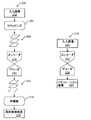
入力画像からシミュレーション画像を生成するように構成されたシステムの1つの実施形態は、図1に示される。本システムは、1つ以上のコンピュータサブシステム(例えばコンピュータサブシステム36およびコンピュータサブシステム102)、および1つ以上のコンピュータサブシステムによって実行される1つ以上の構成要素100を含む。いくつかの実施形態において、本システムは、撮像システム(またはサブシステム)10を含む。図1の実施形態において、撮像システムは、標本の物理的なバージョンの上に光を走査するかまたはそれに光を向けると同時に、標本から光を検出し、それにより標本のための画像を生成するように構成されている。撮像システムはまた、これら走査すること(または向けること)および検出することを複数モードで実施するように構成され得る。
One embodiment of the system configured to generate a simulation image from the input image is shown in FIG. The system includes one or more computer subsystems (eg,
1つの実施形態において、標本はウェハである。ウェハは、当該技術分野で知られている任意のウェハを含み得る。別の実施形態において、標本はレチクルである。レチクルは、当該技術分野で知られている任意のレチクルを含み得る。 In one embodiment, the specimen is a wafer. The wafer may include any wafer known in the art. In another embodiment, the specimen is a reticle. The reticle may include any reticle known in the art.
1つの実施形態において、撮像システムは、光学ベースの撮像システムである。この様式では、いくつかの実施形態において、本明細書にさらに説明される2つ以上のエンコーダ層に入力される画像は、光学ベースの撮像システムによって生成される。1つのそのような例において、図1に示されるシステムの実施形態では、光学ベースの撮像システム10は、標本14に光を向けるように構成された照明サブシステムを含む。照明サブシステムは、少なくとも1つの光源を含む。例えば、図1に示されるように、照明サブシステムは光源16を含む。1つの実施形態において、照明サブシステムは、1つ以上の斜角および/または1つ以上の法線角を含み得る1つ以上の入射角で光を標本に向けるように構成されている。例えば、図1に示されるように、光源16からの光は、斜めの入射角で、光学素子18および次いでレンズ20を通って標本14に向けられる。斜めの入射角は、任意の好適な斜めの入射角を含み得、それは、例えば標本の特徴によって変化し得る。
In one embodiment, the imaging system is an optical-based imaging system. In this manner, in some embodiments, the images input to the two or more encoder layers described further herein are produced by an optical-based imaging system. In one such example, in an embodiment of the system shown in FIG. 1, the optical-based
撮像システムは、異なる時に異なる入射角で標本に光を向けるように構成され得る。例えば、撮像システムは、図1に示されるものとは異なる入射角で光を標本に向けることができるように、照明サブシステムの1つ以上の要素の1つ以上の特徴を変更するように構成され得る。1つのそのような例において、撮像システムは、異なる斜めの入射角または法線の(もしくは法線に近い)入射角で光を標本に向けることができるように、光源16、光学素子18、およびレンズ20を動かすように構成され得る。
The imaging system can be configured to direct light to the specimen at different times and at different angles of incidence. For example, the imaging system is configured to modify one or more features of one or more elements of the lighting subsystem so that light can be directed at the specimen at an angle of incidence different from that shown in FIG. Can be done. In one such example, the imaging system has a
いくつかの場合において、撮像システムは、同時に2つ以上の入射角で光を標本に向けるように構成され得る。例えば、照明サブシステムは、2つ以上の照明チャネルを含み得、照明チャネルのうちの1つは、図1に示されるように光源16、光学素子18、およびレンズ20を含み得、照明チャネルのうちの別のもの(図示せず)は、異なってもしくは同じに構成され得る同様の要素を含み得るか、または少なくとも光源およびおそらくは本明細書にさらに説明されるものなどの1つ以上の他の構成要素を含み得る。そのような光が他の光と同時に標本に向けられる場合、異なる入射角で標本に向けられる光の1つ以上の特徴(例えば、波長、偏光など)が、異なり得るため、異なる入射角で標本の照明から生じる光を検出器において互いと区別することができる。
In some cases, the imaging system may be configured to direct light at two or more angles of incidence at the same time. For example, a lighting subsystem may include two or more lighting channels, one of which may include a
別の場合において、照明サブシステムは、1つのみの光源(例えば図1に示される光源16)を含み得、光源からの光は、照明サブシステムの1つ以上の光学素子(図示せず)によって(例えば、波長、偏光などに基づいて)異なる光経路内へ分離され得る。異なる光経路の各々における光が、次いで標本に向けられる。複数の照明チャネルが、同時にまたは異なる時(例えば、異なる照明チャネルを使用して標本を連続して照明するとき)に標本に光を向けるように構成され得る。別の場合において、同じ照明チャネルが、異なる時に異なる特徴を有する標本に光を向けるように構成され得る。例えば、いくつかの場合において、光学素子18は、スペクトルフィルタとして構成され得、スペクトルフィルタの特性は、光の異なる波長を異なる時に標本に向けることができるように、様々な異なるやり方で(例えば、スペクトルフィルタを取り換えることによって)変えることができる。照明サブシステムは、異なるまたは同じ特徴を有する光を異なるまたは同じ入射角で連続してまたは同時に標本に向けるための当該技術分野において知られている任意の他の構成を有してもよい。
In another case, the lighting subsystem may include only one light source (eg,
1つの実施形態において、光源16は、広帯域プラズマ(BBP)光源を含み得る。この様式では、光源によって生成され標本に向けられる光は、広帯域光を含み得る。しかしながら、光源は、レーザなどの任意の他の好適な光源を含んでもよい。レーザは、当該技術分野において知られている任意の好適なレーザを含み得、当該技術分野において知られている任意の好適な波長で光を生成するように構成され得る。加えて、レーザは、単色またはほぼ単色である光を生成するように構成され得る。この様式では、レーザは狭帯域レーザであってもよい。光源はまた、複数の離散した波長または波帯で光を生成する多色光源を含み得る。
In one embodiment, the
光学素子18からの光は、レンズ20によって標本14に焦点合わせされ得る。レンズ20は、図1では単一の屈折光学素子として示されるが、実際には、レンズ20は、共同して光学素子からの光を標本に焦点合わせするいくつかの屈折および/または反射光学素子を含み得ることが理解されるものとする。図1に示され本明細書に説明される照明サブシステムは、任意の他の好適な光学素子(図示せず)を含んでもよい。そのような光学素子の例としては、当該技術分野で知られている任意のそのような好適な光学素子を含み得る、偏光構成要素、スペクトルフィルタ、空間フィルタ、反射光学素子、アポタイザ、ビームスプリッタ、アパーチャ、および同様のものが挙げられるが、これらに限定されない。加えて、撮像システムは、撮像に使用される予定の照明の種類に基づいて照明サブシステムの要素のうちの1つ以上を変更するように構成され得る。
The light from the
撮像システムはまた、標本の上に光を走査させるように構成された走査サブシステムを含み得る。例えば、撮像システムは、標本14が検査中に載置されるステージ22を含み得る。走査サブシステムは、光を標本の上に走査することができるように標本を動かすように構成され得る(ステージ22を含む)任意の好適な機械的および/またはロボットアセンブリを含み得る。加えて、または代替的に、撮像システムは、撮像システムの1つ以上の光学素子が標本の上で光の何らかの走査を実施するように構成され得る。光は、蛇行したような経路またはらせん経路などの任意の好適な方式で標本の上に走査され得る。
The imaging system may also include a scanning subsystem configured to scan light over the specimen. For example, the imaging system may include
撮像システムは、1つ以上の検出チャネルをさらに含む。1つ以上の検出チャネルのうちの少なくとも1つは、システムによって標本の照明により標本から光を検出するように、および検出された光に応答して出力を生成するように構成された検出器を含む。例えば、図1に示される撮像システムは、2つの検出チャネルを含み、一方は、集光器24、要素26、および検出器28によって形成され、もう一方は、集光器30、要素32、および検出器34によって形成される。図1に示されるように、2つの検出チャネルは、異なる集光角度で光を収集および検出するように構成されている。いくつかの場合において、両方の検出チャネルが、散乱光を検出するように構成されており、これらの検出チャネルは、標本から異なる角度で散乱される光を検出するように構成されている。しかしながら、検出チャネルの1つ以上が、標本からの別の種類の光(例えば反射光)を検出するように構成されていてもよい。
The imaging system further includes one or more detection channels. At least one of the one or more detection channels is a detector configured by the system to detect light from the specimen by illuminating the specimen and to produce output in response to the detected light. Including. For example, the imaging system shown in FIG. 1 comprises two detection channels, one formed by the
図1にさらに示されるように、両方の検出チャネルが、紙面内に位置付けられて示され、照明サブシステムも紙面内に位置付けられて示される。したがって、この実施形態では、両方の検出チャネルが、入射面内に位置付けられる(例えば、入射面内の中心に置かれる)。しかしながら、検出チャネルのうちの1つ以上は、入射面外に位置付けられ得る。例えば、集光器30、要素32、および検出器34によって形成される検出チャネルは、入射面から外に散乱される光を収集および検出するように構成され得る。したがって、そのような検出チャネルは、「サイド」チャネルと一般に呼ばれ得、そのようなサイドチャネルは、入射面に略垂直である平面の中心に置かれ得る。
As further shown in FIG. 1, both detection channels are shown positioned in the paper and the lighting subsystem is also shown in the paper. Therefore, in this embodiment, both detection channels are positioned within the plane of incidence (eg, centered within the plane of incidence). However, one or more of the detection channels can be located outside the plane of incidence. For example, the detection channel formed by the condenser 30,
図1は、2つの検出チャネルを含む撮像システムの実施形態を示すが、撮像システムは、異なる数の検出チャネル(例えば、1つのみの検出チャネルまたは2つ以上の検出チャネル)を含んでもよい。1つのそのような場合において、集光器30、要素32、および検出器34によって形成される検出チャネルは、上記のような1つのサイドチャネルを形成してもよく、撮像システムは、入射面の反対側に位置付けられる別のサイドチャネルとして形成される追加の検出チャネル(図示せず)を含んでもよい。したがって、撮像システムは、入射面の中心に置かれ、標本表面に対して法線であるかまたは法線に近い散乱角度で光を収集および検出するように構成された、集光器24、要素26、および検出器28を含む検出チャネルを含み得る。この検出チャネルは、したがって、「トップ」チャネルと一般に呼ばれ得、撮像システムはまた、上記のように構成された2つ以上のサイドチャネルを含み得る。そのようなものとして、撮像システムは、少なくとも3つのチャネル(すなわち、1つのトップチャネルおよび2つのサイドチャネル)を含み得、少なくとも3つのチャネルの各々が、独自の集光器を有し、その各々が、他の集光器の各々とは異なる散乱角度で光を収集するように構成されている。
Although FIG. 1 shows an embodiment of an imaging system that includes two detection channels, the imaging system may include a different number of detection channels (eg, only one detection channel or two or more detection channels). In one such case, the detection channels formed by the condenser 30,
上にさらに説明されるように、撮像システムに含まれる検出チャネルの各々は、散乱光を検出するように構成され得る。したがって、図1に示される撮像システムは、標本の暗視野(DF)撮像のために構成され得る。しかしながら、撮像システムはまた、または代替的に、標本の明視野(BF)撮像のために構成されている検出チャネルを含み得る。言い換えると、撮像システムは、標本から鏡面的に反射された光を検出するように構成されている少なくとも1つの検出チャネルを含み得る。したがって、本明細書に説明される撮像システムは、DFのみ、BFのみ、またはDFおよびBFの両方のために構成され得る。集光器の各々は、図1では単一の屈折光学素子として示されるが、集光器の各々は、1つ以上の屈折光学素子および/または1つ以上の反射光学素子を含み得ることが理解されるものとする。 As further described above, each of the detection channels included in the imaging system may be configured to detect scattered light. Therefore, the imaging system shown in FIG. 1 can be configured for dark field (DF) imaging of a specimen. However, imaging systems may also, or optionally, include detection channels configured for bright field (BF) imaging of specimens. In other words, the imaging system may include at least one detection channel that is configured to detect mirror-reflected light from the specimen. Therefore, the imaging system described herein can be configured for DF only, BF only, or both DF and BF. Each of the condensers is shown as a single refracting optic in FIG. 1, but each of the condensers may include one or more refracting optics and / or one or more catoptrics. It shall be understood.
1つ以上の検出チャネルは、当該技術分野で知られている任意の好適な検出器を含み得る。例えば、検出器は、光電子増倍管(PMT)、電荷結合デバイス(CCD)、時間遅延積分(TDI)カメラ、および当該技術分野で知られている任意の他の好適な検出器を含み得る。検出器はまた、非撮像検出器または撮像検出器を含み得る。この様式では、検出器が非撮像検出器である場合、検出器の各々は、強度などの散乱光の特定の特徴を検出するように構成され得るが、そのような特徴を撮像平面内の位置の関数として検出するように構成されない場合がある。そのようなものとして、撮像システムの検出チャネルの各々に含まれる検出器の各々によって生成される出力は、信号またはデータであり得るが、画像信号または画像データではない場合がある。そのような場合において、コンピュータサブシステム36などのコンピュータサブシステムは、検出器の非撮像出力から標本の画像を生成するように構成され得る。しかしながら、他の場合において、検出器は、画像信号または画像データを生成するように構成されている撮像検出器として構成され得る。したがって、撮像システムは、いくつかのやり方で本明細書に説明される画像を生成するように構成され得る。
The one or more detection channels may include any suitable detector known in the art. For example, the detector may include a photomultiplier tube (PMT), a charge coupling device (CCD), a time-delayed integral (TDI) camera, and any other suitable detector known in the art. The detector may also include a non-imaging detector or an imaging detector. In this mode, if the detector is a non-imaging detector, each of the detectors may be configured to detect certain features of the scattered light, such as intensity, which are located in the imaging plane. It may not be configured to be detected as a function of. As such, the output produced by each of the detectors included in each of the detection channels of the imaging system may be a signal or data, but not an image signal or data. In such cases, a computer subsystem, such as the
図1は、本明細書に説明されるシステム実施形態に含まれ得る、または本明細書に説明されるシステム実施形態によって使用される画像を生成し得る、撮像システムまたはサブシステムの構成を全体的に例証するために本明細書に提供されるということに留意されたい。当然ながら、本明細書に説明される撮像システム構成は、市販の撮像システムを設計するときに通常実施されるように、撮像システムのパフォーマンスを最適化するために変更されてもよい。加えて、本明細書に説明されるシステムは、カリフォルニア州ミルピタスのKLA−Tencorから市販されているツールの29xx/39xxおよびPuma 9xxxシリーズなど、既存のシステムを使用して(例えば、既存のシステムに本明細書に説明される機能性を追加することによって)実装され得る。いくつかのそのようなシステムでは、本明細書に説明される実施形態は、システムの選択的な機能性として提供され得る(例えば、システムの他の機能性に加えて)。代替的に、本明細書に説明される撮像システムは、完全に新しい撮像システムを提供するために「ゼロから」設計されてもよい。 FIG. 1 is an overall configuration of an imaging system or subsystem that can be included in the system embodiments described herein or that can produce images used by the system embodiments described herein. It should be noted that it is provided herein to illustrate. Of course, the imaging system configuration described herein may be modified to optimize the performance of the imaging system, as is usually done when designing a commercial imaging system. In addition, the systems described herein use existing systems such as the 29xx / 39xx and Puma 9xxx series of tools commercially available from KLA-Tencor in Milpitas, CA (eg, to existing systems). It can be implemented (by adding the functionality described herein). In some such systems, the embodiments described herein may be provided as selective functionality of the system (eg, in addition to other functionality of the system). Alternatively, the imaging system described herein may be designed "from scratch" to provide a completely new imaging system.
撮像システムのコンピュータサブシステム36は、コンピュータサブシステムが標本の走査中に検出器によって出力された出力を受信することができるように、任意の好適な様式で(例えば、「有線」および/または「無線」伝送媒体を含み得る1つ以上の伝送媒体を介して)撮像システムの検出器に結合され得る。コンピュータサブシステム36は、検出器の出力を使用して、本明細書にさらに説明されるいくつかの機能を実施するように構成され得る。
The
図1に示されるコンピュータサブシステム(ならびに本明細書に説明される他のコンピュータサブシステム)は、本明細書では、コンピュータシステムとも呼ばれ得る。本明細書に説明されるコンピュータサブシステムまたはシステムの各々は、パーソナルコンピュータシステム、画像コンピュータ、メインフレームコンピュータシステム、ワークステーション、ネットワークアプライアンス、インターネットアプライアンス、または他のデバイスを含め、様々な形態をとり得る。一般に、「コンピュータシステム」という用語は、メモリ媒体からの命令を実行する1つ以上のプロセッサを有する任意のデバイスを包含すると広く定義され得る。コンピュータサブシステムまたはシステムはまた、パラレルプロセッサなどの、当該技術分野で知られている任意の好適なプロセッサを含み得る。加えて、コンピュータサブシステムまたはシステムは、スタンドアローンまたはネットワーク化したツールのいずれかとして、高速処理およびソフトウェアを備えたコンピュータプラットフォームを含み得る。 The computer subsystem shown in FIG. 1 (as well as other computer subsystems described herein) may also be referred to herein as computer systems. Each of the computer subsystems or systems described herein may take various forms, including personal computer systems, imaging computers, mainframe computer systems, workstations, network appliances, internet appliances, or other devices. .. In general, the term "computer system" can be broadly defined to include any device having one or more processors that execute instructions from a memory medium. The computer subsystem or system may also include any suitable processor known in the art, such as a parallel processor. In addition, the computer subsystem or system may include a computer platform with high speed processing and software, either as a stand-alone or networked tool.
本システムが2つ以上のコンピュータサブシステムを含む場合、異なるコンピュータサブシステムが、画像、データ、情報、命令などを、本明細書にさらに説明されるようにコンピュータサブシステム間で送信することができるように互いに結合され得る。例えば、コンピュータサブシステム36は、当該技術分野で知られている任意の好適な有線および/または無線伝送媒体を含み得る任意の好適な伝送媒体によって、図1の破線によって示されるようにコンピュータサブシステム102に結合され得る。そのようなコンピュータサブシステムのうちの2つ以上はまた、共有コンピュータ可読記憶媒体(図示せず)によって有効に結合され得る。
If the system includes more than one computer subsystem, different computer subsystems can transmit images, data, information, instructions, etc. between the computer subsystems as further described herein. Can be combined with each other. For example, the
撮像システムは、光学または光ベースの撮像システムであると上に説明されるが、撮像システムは、電子ビームベースの撮像システムであってもよい。この様式では、いくつかの実施形態において、本明細書に説明される2つ以上のエンコーダ層に入力される画像は、電子ビームベースの撮像システムによって生成される。図1aに示される1つのそのような実施形態において、撮像システムは、コンピュータサブシステム124に結合されてもよい電子カラム122を含む。図1aにも示されるように、電子カラムは、1つ以上の要素130によって標本128に焦点合わせされる電子を生成するように構成された電子ビーム源126を含む。電子ビーム源は、例えば、カソード源またはエミッタチップを含み得、1つ以上の要素130は、例えば、ガンレンズ、アノード、ビーム制限アパーチャ、ゲート弁、ビーム電流選択アパーチャ、対物レンズ、および走査サブシステムを含み得、それらのすべてが当該技術分野で知られている任意のそのような好適な要素を含み得る。
Although the imaging system is described above as an optical or optical based imaging system, the imaging system may be an electron beam based imaging system. In this fashion, in some embodiments, the images input to the two or more encoder layers described herein are generated by an electron beam based imaging system. In one such embodiment shown in FIG. 1a, the imaging system includes an
標本から戻ってきた電子(例えば二次電子)は、1つ以上の要素132によって検出器134に焦点合わせされ得る。1つ以上の要素132は、例えば、走査サブシステムを含み得、それは要素130に含まれる同じ走査サブシステムであり得る。
The electrons returned from the specimen (eg, secondary electrons) can be focused on the
電子カラムは、当該技術分野で知られている任意の他の好適な要素を含み得る。加えて、電子カラムは、2014年に4月4日にジャン(Jiang)らに対して発行された米国特許第8,664,594号、2014年4月8日にコジマ(Kojima)らに対して発行された同第8,692,204号、2014年4月15日にガベンズ(Gubbens)らに対して発行された同第8,698,093号、および2014年5月6日にマクドナルド(MacDonald)らに対して発行された同第8,716,662号に説明されるようにさらに構成されてもよく、これらは、本明細書に完全に明記されるかのように引用により援用する。 The electronic column may include any other suitable element known in the art. In addition, the electronic column was issued to US Pat. No. 8,664,594 issued to Jiang et al. On April 4, 2014, and to Kojima et al. On April 8, 2014. Issued No. 8,692,204, No. 8,692,204 issued to Gavens et al. On April 15, 2014, and McDonald's No. 8,698,093 issued on May 6, 2014. It may be further configured as described in No. 8,716,662 issued to MacDonald et al., Which is incorporated by reference as if fully specified herein. ..
図1aでは、電子カラムは、電子が斜めの入射角で標本に向けられ、別の斜角で標本から散乱されるように構成されて示されるが、電子ビームは、任意の好適な角度で、標本に向けられそこから散乱され得るということが理解されるものとする。加えて、電子ビームベースの撮像システムは、本明細書にさらに説明されるように標本の画像を生成するために複数のモードを使用するように構成され得る(例えば、異なる照明角度、集光角度などで)。電子ビームベースの撮像システムの複数のモードは、撮像システムの任意の画像生成パラメータが異なり得る。 In FIG. 1a, the electron column is configured such that electrons are directed at the specimen at an oblique angle of incidence and scattered from the specimen at another oblique angle, whereas the electron beam is at any suitable angle. It shall be understood that it can be directed at the specimen and scattered from it. In addition, electron beam-based imaging systems can be configured to use multiple modes to generate images of the specimen as further described herein (eg, different illumination angles, focusing angles). Etc). Multiple modes of an electron beam-based imaging system can differ from any image generation parameter of the imaging system.
コンピュータサブシステム124は、上記のように検出器134に結合され得る。検出器は、標本の表面から戻ってきた電子を検出し、それにより標本の電子ビーム画像を形成し得る。電子ビーム画像は、任意の好適な電子ビーム画像を含み得る。コンピュータサブシステム124は、検出器134によって生成された出力を使用して、標本について本明細書にさらに説明される1つ以上の機能を実施するように構成され得る。コンピュータサブシステム124は、本明細書に説明される任意の追加のステップを実施するように構成され得る。図1aに示される撮像システムを含むシステムは、本明細書に説明されるようにさらに構成されてもよい。
The
図1aは、本明細書に説明される実施形態に含まれ得る電子ビームベースの撮像システムの構成を全体的に例証するために、本明細書に提供されるということに留意されたい。上記の光学ベースの撮像システムのように、本明細書に説明される電子ビームベースの撮像システム構成は、市販の撮像システムを設計するときに通常実施されるように、撮像システムのパフォーマンスを最適化するために変更されてもよい。加えて、本明細書に説明されるシステムは、KLA−Tencorから市販されているツールのeSxxxおよびeDR−xxxxシリーズなど、既存のシステムを使用して(例えば、既存のシステムに本明細書に説明される機能性を追加することによって)実装され得る。いくつかのそのようなシステムでは、本明細書に説明される実施形態は、システムの選択的な機能性として提供され得る(例えば、システムの他の機能性に加えて)。代替的に、本明細書に説明されるシステムは、完全に新しいシステムを提供するために「ゼロから」設計されてもよい。 It should be noted that FIG. 1a is provided herein to illustrate the overall configuration of an electron beam-based imaging system that may be included in the embodiments described herein. Like the optical-based imaging system described above, the electron beam-based imaging system configuration described herein optimizes the performance of the imaging system as is commonly practiced when designing commercial imaging systems. May be modified to. In addition, the systems described herein use existing systems, such as the eSxxx and eDR-xxx series of tools commercially available from KLA-Tencor (eg, described herein for existing systems). Can be implemented (by adding functionality to be done). In some such systems, the embodiments described herein may be provided as selective functionality of the system (eg, in addition to other functionality of the system). Alternatively, the system described herein may be designed "from scratch" to provide a completely new system.
撮像システムは、光学ベースまたは電子ビームベースの撮像システムであると上に説明されるが、撮像システムは、イオンビームベースの撮像システムであってもよい。そのような撮像システムは、電子ビーム源が当該技術分野で知られている任意の好適なイオンビーム源で置き換えられ得るということを除き、電子ビームベースのサブシステムに関して図1aに示されるように構成され得る。加えて、撮像システムは、市販の集束イオンビーム(FIB)システム、ヘリウムイオン顕微鏡検査(HIM)システム、および二次イオン質量分析(SIMS)システムに含まれるものなど、任意の他の好適なイオンビームベースの撮像システムであってもよい。 Although the imaging system is described above as an optical-based or electron beam-based imaging system, the imaging system may be an ion beam-based imaging system. Such an imaging system is configured as shown in FIG. 1a with respect to an electron beam based subsystem, except that the electron beam source can be replaced with any suitable ion beam source known in the art. Can be done. In addition, the imaging system is any other suitable ion beam, such as those included in commercially available focused ion beam (FIB) systems, helium ion microscopy (HIM) systems, and secondary ion mass spectrometry (SIMS) systems. It may be a base imaging system.
上に記載されるように、撮像システムは、標本の物理的なバージョンの上に、エネルギー(例えば、光または電子)を走査し、それにより標本の物理的なバージョンの実画像を生成するように構成されている。この様式では、撮像システムは、「仮想」システムではなく「実」システムとして構成され得る。例えば、記憶媒体(図示せず)および図1に示されるコンピュータサブシステム102は、「仮想」システムとして構成され得る。具体的には、記憶媒体およびコンピュータサブシステムは、撮像サブシステム10の部分ではなく、標本の物理的なバージョンを取り扱うためのいかなる能力も有しない。言い換えると、仮想システムとして構成されたシステムでは、その1つ以上の「検出器」の出力は、実システムの1つ以上の検出器によって以前に生成され、仮想システムに格納されている出力であり得、「走査」中、仮想システムは、標本が走査されているかのように格納された出力を再生し得る。この様式では、仮想システムを用いて標本を走査することは、物理的な標本が実システムを用いて走査されているのと同じであるように見え得るが、現実には、この「走査」は、標本が走査され得るのと同じ様式で標本の出力を単に再生することに関与する。「仮想」検査システムとして構成されたシステムおよび方法は、同一出願人による2012年2月28日にバスカー(Bhaskar)らに対して発行された米国特許第8,126,255号、および2015年12月29日にダフィー(Duffy)らに発行された同第9,222,895号に説明されており、それらの両方が、本明細書に完全に明記されるかのように引用により援用する。本明細書に説明される実施形態は、これらの特許において説明されるようにさらに構成され得る。例えば、本明細書に説明される1つ以上のコンピュータサブシステムは、これらの特許において説明されるようにさらに構成され得る。加えて、1つ以上の仮想システムを中央計算記憶(CCS)システムとして構成することは、ダフィー(Duffy)に対する上に参照した特許において説明されるように実施され得る。本明細書に説明される持続記憶機序は、CCSアーキテクチャなどの分散計算および記憶を有することができるが、本明細書に説明される実施形態はそのアーキテクチャに限定されない。
As described above, the imaging system may scan energy (eg, light or electron) on top of the physical version of the specimen, thereby producing a real image of the physical version of the specimen. It is configured. In this fashion, the imaging system can be configured as a "real" system rather than a "virtual" system. For example, the storage medium (not shown) and the computer subsystem 102 shown in FIG. 1 can be configured as a "virtual" system. Specifically, the storage medium and computer subsystem are not part of the
さらに上に記載されるように、撮像システムは、複数のモードで標本の画像を生成するように構成され得る。一般に、「モード」は、標本の画像を生成することに使用される撮像システムのパラメータの値、または標本の画像を生成するために使用される出力によって規定され得る。したがって、異なるモードは、撮像システムの撮像パラメータのうちの少なくとも1つに対する値が異なり得る。例えば、光学ベースの撮像システムの1つの実施形態において、複数のモードのうちの少なくとも1つは、複数のモードのうちの少なくとも1つの他のモードに使用される照明の光の少なくとも1つの波長とは異なる照明の光の少なくとも1つの波長を使用する。モードは、異なるモードでは本明細書にさらに説明されるように照明波長が異なり得る(例えば、異なる光源、異なるスペクトルフィルタなどを使用することによって)。別の実施形態において、複数のモードのうちの少なくとも1つは、複数のモードのうちの少なくとも1つの他のモードに使用される撮像システムの照明チャネルとは異なる撮像システムの照明チャネルを使用する。例えば、上に記載されるように、撮像システムは、2つ以上の照明チャネルを含んでもよい。そのようなものとして、異なるモードでは異なる照明チャネルが使用され得る。 As further described above, the imaging system can be configured to generate images of the specimen in multiple modes. In general, the "mode" can be defined by the values of the parameters of the imaging system used to generate the image of the sample, or the output used to generate the image of the sample. Therefore, different modes can have different values for at least one of the imaging parameters of the imaging system. For example, in one embodiment of an optical-based imaging system, at least one of the plurality of modes is with at least one wavelength of illumination light used in at least one other mode of the plurality of modes. Uses at least one wavelength of light of different illumination. The modes may differ in illumination wavelength in different modes as further described herein (eg, by using different light sources, different spectral filters, etc.). In another embodiment, at least one of the plurality of modes uses a different imaging system illumination channel than the imaging system illumination channel used for at least one other mode of the plurality of modes. For example, as described above, the imaging system may include more than one illumination channel. As such, different lighting channels may be used in different modes.
1つの実施形態において、撮像システムは、検査システムである。例えば、本明細書に説明される光学および電子ビーム撮像システムは、検査システムとして構成され得る。この様式では、いくつかの実施形態において、2つ以上のエンコーダ層に入力される画像は、検査システムによって生成される。別の実施形態において、撮像システムは、欠陥レビューシステムである。例えば、本明細書に説明される光学および電子ビーム撮像システムは、欠陥レビューシステムとして構成され得る。さらなる実施形態において、撮像システムは、計測システムである。例えば、本明細書に説明される光学および電子ビーム撮像システムは、計測システムとして構成され得る。この様式では、いくつかの実施形態において、2つ以上のエンコーダ層に入力される画像は、計測システムによって生成される。具体的には、本明細書に説明され、図1および図1aに示される撮像システムの実施形態は、それらが使用されることになる用途に応じて異なる撮像能力を提供するために1つ以上のパラメータが変更され得る。1つのそのような例において、図1に示される撮像システムは、それが検査ではなく欠陥レビューまたは計測に使用される場合には、より高い解像度を有するように構成され得る。言い換えると、図1および図1aに示される撮像システムの実施形態は、異なる用途に多かれ少なかれ好適である異なる撮像能力を有する撮像システムを形成するために、当業者には明白であろういくつかの様式で調整することができる撮像システムのいくつかの一般的なおよび様々な構成を説明している。 In one embodiment, the imaging system is an inspection system. For example, the optical and electron beam imaging systems described herein can be configured as inspection systems. In this mode, in some embodiments, the images input to the two or more encoder layers are generated by the inspection system. In another embodiment, the imaging system is a defect review system. For example, the optical and electron beam imaging systems described herein can be configured as defect review systems. In a further embodiment, the imaging system is a measurement system. For example, the optical and electron beam imaging systems described herein can be configured as measurement systems. In this mode, in some embodiments, the images input to the two or more encoder layers are generated by the measurement system. Specifically, one or more embodiments of imaging systems as described herein and shown in FIGS. 1 and 1a are used to provide different imaging capabilities depending on the application in which they will be used. Parameters can be changed. In one such example, the imaging system shown in FIG. 1 may be configured to have a higher resolution if it is used for defect review or measurement rather than inspection. In other words, the embodiments of the imaging system shown in FIGS. 1 and 1a will be apparent to those skilled in the art to form imaging systems with different imaging capabilities that are more or less suitable for different applications. Describes some common and various configurations of imaging systems that can be styled.
1つ以上のコンピュータサブシステムは、本明細書に説明される撮像サブシステムによって生成された標本のための画像を取得するように構成され得る。画像を取得することは、本明細書に説明される撮像システムのうちの1つを使用して(例えば、標本に光または電子ビームを向け、標本から光または電子ビームを検出することによって)実施され得る。この様式では、画像を取得することは、物理的な標本自体および何らかの種類の撮像ハードウェアを使用して実施され得る。しかしながら、画像を取得することは、撮像ハードウェアを使用して標本を撮像することを必ずしも含まない。例えば、別のシステムおよび/または方法が、画像を生成し得、生成された画像を本明細書に説明されるような仮想検査システムなどの1つ以上の記憶媒体または本明細書に説明される別の記憶媒体に格納し得る。したがって、画像を取得することは、画像が格納されている記憶媒体から画像を取得することを含み得る。 One or more computer subsystems may be configured to acquire images for specimens produced by the imaging subsystem described herein. Obtaining an image is performed using one of the imaging systems described herein (eg, by directing a light or electron beam at the specimen and detecting the light or electron beam from the specimen). Can be done. In this fashion, the acquisition of images can be performed using the physical specimen itself and some type of imaging hardware. However, acquiring an image does not necessarily include imaging the specimen using imaging hardware. For example, another system and / or method may generate an image and the generated image is described herein in one or more storage media, such as a virtual inspection system as described herein. It can be stored in another storage medium. Therefore, acquiring an image may include acquiring the image from a storage medium in which the image is stored.
コンピュータサブシステム、例えば、コンピュータサブシステム36および/またはコンピュータサブシステム102によって実行される構成要素、例えば、図1に示される構成要素100は、ニューラルネットワーク104を含む。ニューラルネットワークは、標本のための画像の特徴部を決定するように構成された2つ以上のエンコーダ層を含む。「エンコーダ」という用語は、一般に、入力データの情報内容をよりコンパクトな表現に「エンコードする」ニューラルネットワークまたはニューラルネットワークの部分を指す。エンコードプロセスは、効果的に不可逆または可逆であり得る。加えて、エンコードプロセスは、人間による解釈が可能な場合とそうでない場合がある。エンコードされた表現は、スカラ値のベクトルまたは分布であり得る。
The component executed by the computer subsystem, for example, the
ニューラルネットワークはまた、決定された特徴部から1つ以上のシミュレーション画像を生成するように構成された2つ以上のデコーダ層を含む。「デコーダ」という用語は、エンコードされたコンパクトな表現を、おそらくは元の入力および/またはその入力の結合表現に「デコードする」ニューラルネットワークまたはニューラルネットワークの部分を指す。本明細書に説明される実施形態は、概して、エンコーダ−デコーダタイプのニューラルネットワーク、特に、本明細書にさらに説明され得る深層生成的モデルに適用可能である。 The neural network also includes two or more decoder layers configured to generate one or more simulation images from the determined features. The term "decoder" refers to a neural network or part of a neural network that "decodes" an encoded compact representation, perhaps into the original input and / or the combined representation of that input. The embodiments described herein are generally applicable to encoder-decoder type neural networks, especially to deep generative models that can be further described herein.
1つの実施形態において、ニューラルネットワークは、深層学習モデルである。一般的に言えば、「深層学習」(深層構造学習、階層学習、または深層機械学習としても知られている)は、データにおける高次抽象化をモデリングすることを試みるアルゴリズムのセットに基づく機械学習の支流である。単純なケースでは、1つは入力信号を受信し1つは出力信号を送信する2つのニューロンのセットが存在し得る。入力層が入力を受信すると、入力層は、次の層に入力の修正されたバージョンを引き渡す。深層ネットワークでは、入力と出力との間に多くの層が存在し(また、層はニューロンでできていないが、層をそのように考えることを手助けすることができる)、複数の線形および非線形変換からなる複数の処理層をアルゴリズムが使用することを可能にする。 In one embodiment, the neural network is a deep learning model. Generally speaking, "deep learning" (also known as deep structure learning, hierarchical learning, or deep machine learning) is machine learning based on a set of algorithms that attempt to model higher-order abstractions in data. It is a tributary of. In a simple case, there can be a set of two neurons, one receiving the input signal and one transmitting the output signal. When the input layer receives the input, the input layer passes the modified version of the input to the next layer. In deep networks, there are many layers between inputs and outputs (and layers are not made up of neurons, but can help think of layers that way), and multiple linear and non-linear transformations. Allows the algorithm to use multiple processing layers consisting of.
深層学習は、データの学習表現に基づく機械学習法の広範なグループの部分である。観察(例えば、画像)は、ピクセルあたりの強度値のベクトルなどの多くのやり方、またはエッジのセット、特定の形状の領域などのより抽象的なやり方で表すことができる。いくつかの表現は、学習タスク(例えば、顔認識または表情認識)を単純化することにおいて他の表現よりも優れている。深層学習の有望な点の1つは、人手による特徴量(handcrafted feature)を教師なしまたは半教師ありの特徴部学習および階層特徴部抽出のための効率的なアルゴリズムで置き換えることである。 Deep learning is part of an extensive group of machine learning methods based on learning representations of data. Observations (eg, images) can be represented in many ways, such as a vector of intensity values per pixel, or in a more abstract way, such as a set of edges, a region of a particular shape. Some expressions are superior to others in simplifying learning tasks (eg, face recognition or facial expression recognition). One of the promising points of deep learning is to replace manual features (handcrafted features) with efficient algorithms for unsupervised or semi-supervised feature learning and hierarchical feature extraction.
この分野における研究は、より優れた表現を作り、これらの表現を大規模のラベル化されていないデータから学習するモデルを作成することを試みている。表現の一部は、神経科学の進歩に触発されたものであり、様々な刺激と関連する脳内のニューロン反応との関係を規定することを試みる神経信号など、神経系における情報処理および通信パターンの解釈に大まかに基づいている。 Research in this area attempts to create better representations and models that learn these representations from large amounts of unlabeled data. Some of the expressions are inspired by advances in neuroscience, and information processing and communication patterns in the nervous system, such as neural signals that attempt to define the relationship between various stimuli and associated neuronal responses in the brain. Roughly based on the interpretation of.
深層ニューラルネットワーク、畳み込み深層ニューラルネットワーク、深層信念ネットワーク(deep belief network)、および再帰型ニューラルネットワークなどの様々な深層学習アーキテクチャが、コンピュータビジョン、自動音声認識、自然言語処理、オーディオ認識、およびバイオインフォマティクスのような分野に適用されており、これらの分野において、深層学習アーキテクチャは、様々なタスクに対して最高水準の結果をもたらすことが示されている。 Various deep learning architectures such as deep neural networks, convolutional deep neural networks, deep belief networks, and recursive neural networks are available for computer vision, automatic speech recognition, natural language processing, audio recognition, and bioinformatics. It has been applied to such fields, where deep learning architectures have been shown to provide the highest standards of results for a variety of tasks.
別の実施形態において、ニューラルネットワークは、機械学習のモデルである。機械学習は、概して、明示的にプログラミングされることなく学習する能力を持ったコンピュータを提供する一種の人工知能(AI)と定義することができる。機械学習は、新たなデータに露出されたときに独習して成長および変化することができるコンピュータプログラムの発展に焦点を合わせる。言い換えると、機械学習は、「明示的にプログラミングされることなく学習する能力をコンピュータに与える」コンピュータサイエンスの亜領域と定義することができる。機械学習は、データから学習することができ、かつデータに対して予測を行うことができるアルゴリズムの研究および構築を探究し、そのようなアルゴリズムは、サンプル入力からモデルを構築することを通して、データ駆動の予測または決定を行うことによる厳密に静的なプログラム命令に従うことを克服する。 In another embodiment, the neural network is a model of machine learning. Machine learning can generally be defined as a type of artificial intelligence (AI) that provides a computer with the ability to learn without being explicitly programmed. Machine learning focuses on the development of computer programs that can self-teach, grow and change when exposed to new data. In other words, machine learning can be defined as a sub-domain of computer science that "gives the computer the ability to learn without being explicitly programmed." Machine learning explores the study and construction of algorithms that can learn from data and make predictions on the data, and such algorithms are data-driven through building models from sample inputs. Overcome obeying strictly static program instructions by making predictions or decisions.
本明細書に説明される機械学習は、「Introduction to Statistical Machine Learning」、スギヤマ(Sugiyama)、モーガン・カウフマン(Morgan Kaufmann)、2016、534 pages、「Discriminative, Generative, and Imitative Learning」、ジェバラ(Jebara)、MIT Thesis、2002、212 pages、および「Principles of Data Mining (Adaptive Computation and Machine Learning)」、ハンド(Hand)ら、MIT Press、2001、578 pagesに説明されるようにさらに実施され得、これらは本明細書に完全に明記されるかのように引用により援用する。本明細書に説明される実施形態は、これらの参照文献において説明されるようにさらに構成され得る。 The machine learning described herein is "Introduction to Statistical Machine Learning", Sugiyama, Morgan Kaufmann, 2016, 534 rage, "Discriminative", "Discriminative", "Discriminative". ), MIT Thisis, 2002, 212 pages, and "Principles of Data Mining (Adaptive Computation and Machine Learning)", Hand et al., MIT Press, 2001, 578 p. Is incorporated by reference as if fully specified herein. The embodiments described herein may be further configured as described in these references.
いくつかの実施形態において、ニューラルネットワークは、生成的モデルである。「生成的」モデルは、概して、事実上確率的であるモデルと定義することができる。言い換えると、「生成的」モデルは、フォワードシミュレーションまたはルールベースの手法を実施するものではなく、そのようなものとして、(シミュレーション画像が生成されている)実画像を生成することに関与するプロセスの物理のモデルが必要でない。代わりに、本明細書にさらに説明されるように、生成的モデルは、データの好適なトレーニングセットに基づいて学習され得る(そのパラメータが学習され得るという点で)。 In some embodiments, the neural network is a generative model. A "generative" model can generally be defined as a model that is virtually stochastic. In other words, the "generative" model does not perform forward simulation or rule-based techniques, but as such, the process involved in generating the real image (where the simulation image is generated). No physical model is needed. Instead, as described further herein, the generative model can be trained based on a suitable training set of data (in that its parameters can be trained).
1つの実施形態において、ニューラルネットワークは、深層生成的モデルとして構成されている。例えば、モデルがいくつかのアルゴリズムまたは変換を実施する複数の層を含み得るという点において、モデルは、深層学習アーキテクチャを有するように構成され得る。モデルの片側または両側の層の数は、本明細書に説明される図面に示されるものとは異なる場合がある。例えば、生成的モデルのエンコーダ側の層の数は、ユースケース依存である。加えて、デコーダ側の層の数は、ユースケース依存であり、エンコーダ側の層の数に依存し得る。一般に、生成的モデルの片側または両側の層の数は、重要ではなく、ユースケース依存である。実用的な目的のため、両サイドの層の好適な範囲は、2層から数十層である。 In one embodiment, the neural network is configured as a deep generative model. For example, a model can be configured to have a deep learning architecture in that the model can contain multiple layers that perform some algorithms or transformations. The number of layers on one or both sides of the model may differ from that shown in the drawings described herein. For example, the number of layers on the encoder side of the generative model is use case dependent. In addition, the number of layers on the decoder side is use case dependent and may depend on the number of layers on the encoder side. In general, the number of layers on one or both sides of the generative model is not important and is use case dependent. For practical purposes, the preferred range of layers on both sides is from two to several tens of layers.
さらなる実施形態において、ニューラルネットワークは、深層ニューラルネットワークであり得、これは、それをトレーニングするために供給されているデータに従って世界をモデル化する重みのセットを有する。ニューラルネットワークは、概して、生物学的な脳が軸索によって繋がっている生物学的な神経の比較的大きなクラスタを用いて問題を解決するやり方を大まかにモデル化する比較的大きなニューラルユニット群に基づく計算手法と定義することができる。各ニューラルユニットは、多くの他のニューラルユニットと接続され、リンクは、接続されたニューラルユニットの活性化状態に対するそれらの効果において強制または抑制となり得る。これらのシステムは、自己学習であり、明示的にプログラムされるのではなくトレーニングされ、ソリューションまたは特徴部検出が従来のコンピュータプログラムでは表現することが難しいエリアにおいて勝っている。 In a further embodiment, the neural network can be a deep neural network, which has a set of weights that model the world according to the data supplied to train it. Neural networks are generally based on relatively large neural units that roughly model how the biological brain solves problems using relatively large clusters of biological nerves connected by axons. It can be defined as a calculation method. Each neural unit is connected to many other neural units, and the links can be coercive or suppressive in their effect on the activated state of the connected neural units. These systems are self-learning, trained rather than explicitly programmed, and are superior in areas where solutions or feature detection are difficult to represent with traditional computer programs.
ニューラルネットワークは、典型的には、複数の層からなり、信号パスは前から後ろへ縦走する。ニューラルネットワークの目的は、人間の脳が行うのと同じやり方で問題を解決することであるが、いくつかのニューラルネットワークは、もっと抽象的である。現代のニューラルネットワークプロジェクトは、典型的には、数千から数百万のニューラルユニットおよび何百万もの接続と連携する。ニューラルネットワークは、当該技術分野で知られている任意の好適なアーキテクチャおよび/または構成を有し得る。 A neural network typically consists of multiple layers, with signal paths traversing from front to back. The purpose of neural networks is to solve problems in the same way that the human brain does, but some neural networks are more abstract. Modern neural network projects typically work with thousands to millions of neural units and millions of connections. The neural network can have any suitable architecture and / or configuration known in the art.
別の実施形態において、ニューラルネットワークは、畳み込みニューラルネットワーク(CNN)である。例えば、本明細書に説明される実施形態は、CNNなどの深層学習概念を利用して、通常解決困難な表現変換問題(例えばレンダリング)を解決することができる。モデルは、当該技術分野で知られている任意のCNN構成またはアーキテクチャを有し得る。別の実施形態において、ニューラルネットワークは、完全畳み込みモデルとして構成されている。追加の実施形態において、ニューラルネットワークは、深層生成的モデル、CNN、生成的敵対的ネット(GAN)、条件付き生成的敵対的ネット(cGAN)、GANおよび変分オートエンコーダ(VAE)、ならびに一部分としてCNNを含むネットワーク(すなわちニューラルネットワークの一部分がCNNとして構成されている)として構成され得、これらすべては、ニューラルネットワークが任意サイズの入力を有することができるように本明細書に説明されるように構成され得る。 In another embodiment, the neural network is a convolutional neural network (CNN). For example, the embodiments described herein can use deep learning concepts such as CNN to solve expression transformation problems (eg, rendering) that are usually difficult to solve. The model can have any CNN configuration or architecture known in the art. In another embodiment, the neural network is configured as a fully convolution model. In additional embodiments, the neural network is a deep generative model, CNN, generative hostile net (GAN), conditional generative hostile net (cGAN), GAN and variant autoencoder (VAE), and as part. It can be configured as a network containing CNNs (ie, a portion of the neural network is configured as a CNN), all of which are described herein so that the neural network can have inputs of any size. Can be configured.
本明細書に説明される実施形態に含まれるGANは、「Generative Adversarial Nets」、グッドフェロウ(Goodfellow)ら、arXiv:1406.2661、June 10,2014、9 pagesに説明されるように構成され得、これを本明細書に完全に明記されるかのように引用により援用する。グッドフェロウ(Goodfellow)らは、敵対的プロセスを介して生成的モデルを予測するための新たなフレームワークについて説明し、ここでは、データ分布を捕捉する生成的モデルG、およびサンプルがGではなくトレーニングデータから来た確率を予測する識別モデルDの2つのモデルが同時にトレーニングされる。Gのトレーニング手順は、Dが誤る確率を最大限にすることである。このフレームワークは、ミニマックス2プレイヤーゲームに対応する。任意関数GおよびDの空間においては、トレーニングデータ分布を回復するGおよび至る所で2分の1に等しいDにより、唯一の解が存在する。GおよびDがマルチプレイヤーパーセプトロンによって規定される場合、システム全体を、バックプロパゲーションを用いてトレーニングすることができる。サンプルのトレーニングまたは生成のいずれかの最中にいかなるマルコフ連鎖または展開された近似的推論ネットワークも必要とされない。実験により、生成されたサンプルの定性的および定量的評価を通してこのフレームワークの可能性が実証されている。本明細書に説明される実施形態のニューラルネットワークは、グッドフェロウ(Goodfellow)らによって説明されるようにさらに構成され得る。 The GANs included in the embodiments described herein can be configured as described in "Generative Adversarial Nets", Good Fellow et al., ArXiv: 1406.2661, June 10, 2014, 9 pages. , This is incorporated by reference as if fully specified herein. Goodfellow et al. Described a new framework for predicting generative models through hostile processes, where generative model G to capture data distributions, and samples trained instead of G. Two models of Discriminative Model D, which predict the probabilities that come from the data, are trained at the same time. G's training procedure is to maximize the probability that D will make a mistake. This framework supports minimax 2-player games. In the space of the arbitrary functions G and D, there is only one solution with G recovering the training data distribution and D equal to half everywhere. If G and D are defined by a multiplayer perceptron, the entire system can be trained with backpropagation. No Markov chain or expanded approximate inference network is required during either training or generation of the sample. Experiments have demonstrated the potential of this framework through qualitative and quantitative evaluation of the samples generated. The neural networks of the embodiments described herein can be further configured as described by Goodfellow et al.
本明細書に説明される実施形態に含まれるCGANは、「Conditional Generative Adversarial Nets」、ミルザ(Mirza)ら、arXiv:1411.1784、November 6,2014、7 pagesに説明されるように構成され得、これを本明細書に完全に明記されるかのように引用により援用する。生成的敵対的ネットは、ジェネレータおよび識別子の両方に対していくつかの追加情報yという条件付けが行われる場合、条件付きモデルに拡張することができる。yは、他の様相からのクラスラベルまたはデータなどのあらゆる種類の補助情報であってもよい。条件付けは、yを追加の入力層として識別子およびジェネレータの両方に供給することによって実施され得る。ジェネレータ内では、前の入力ノイズpz(z)、およびyが、結合隠し表現に組み合わされ、敵対的トレーニングフレームワークは、この隠し表現が組み立てられる方法におけるかなりの柔軟性を可能にする。識別子内では、xおよびyは、識別関数への入力として提示される(いくつかの場合において多層パーセプトロン(MLP)によって具現化される)。そのため2プレイヤーミニマックスゲームの目的関数は、以下のようになる。
![]()
![]()
本明細書に説明される実施形態に含まれるニューラルネットワークは、ミルザ(Mirza)らによる上に援用された参照文献に説明されるようにさらに構成され得る。 The neural networks included in the embodiments described herein can be further configured as described in the references above-incorporated by Mirza et al.
変分オートエンコーダは、深層学習および変分推論の長所を利用し、生成的モデリングに大幅な進歩をもたらす構成要素である。加えて、または代替的に、GANまたは深層生成的敵対的ネットワーク(DGAN)と組み合わせた変分オートエンコーダ(VAE)は、「Adversarial Autoencoders」、マッカーニー(Makhzani)ら、arXiv:1511.05644v2、May 25,2016、16 pagesに説明されるように構成され得、これを本明細書に完全に明記されるかのように引用により援用する。本明細書に説明される実施形態は、この参照文献において説明されるようにさらに構成されてもよい。 Variational autoencoders are components that take advantage of deep learning and variational inference and bring significant advances in generative modeling. In addition, or alternative, variant autoencoders (VAEs) combined with GAN or deep-generation hostile networks (DGANs) include "Adversarial Autoencoders", Mackhani et al., ArXiv: 1511.05644v2, May 25. , 2016, 16 pages, which may be incorporated by reference as if fully specified herein. The embodiments described herein may be further configured as described in this reference.
ニューラルネットワークは、全結合層を含まず、それにより2つ以上のエンコーダ層へ入力される画像のサイズに対する制約を除去する。例えば、現在使用される方法およびシステムにおいて行われ得るように全結合層を使用するのではなく、本明細書に説明されるニューラルネットワークは、全結合層を除去し、それを本明細書にさらに説明されるような1つ以上の畳み込み層で置き換え得る。全結合層を畳み込みで置き換えることによって、ニューラルネットワークは、入力画像サイズとは無関係になり、それはニューラルネットワークが、現在使用されるニューラルネットワークのように入力画像サイズに対する上限を有しないことを意味する。 The neural network does not include a fully connected layer, thereby removing restrictions on the size of the image input to two or more encoder layers. For example, rather than using fully connected layers as can be done in the methods and systems currently used, the neural networks described herein remove the fully connected layers and add them to this specification. It can be replaced by one or more convolutional layers as described. By replacing the fully connected layer with a convolution, the neural network becomes independent of the input image size, which means that the neural network does not have an upper bound on the input image size like the neural networks currently in use.
全結合層を畳み込み層で置き換えることは、以下の条件下で行われ得る。全結合層が2次元(N,D)入力データを取ることを前提とし、ここでNはバッチサイズ、およびDは入力チャネルの数である。多くの場合、再形成層は、4次元入力(N,C,H,W)を、D=C*H*Wを満足する2次元入力(N,D)に変換するために全結合層の前に実施され、ここでCはチャネルの数であり、Hは高さであり、Wは幅である。全結合層がO個の出力チャネルを有する、すなわち全結合層からの出力データ次元が(N,O)であると仮定すると、再形成層および全結合層は、(C,O,H,W)のカーネルサイズでのVALIDパディングを有する畳み込み層で置き換えられ得、結果として生じるネットワークは、任意サイズの入力に対して正確な計算を行うことができる。 Replacing the fully connected layer with a convolutional layer can be done under the following conditions. It is assumed that the fully connected layer takes two-dimensional (N, D) input data, where N is the batch size and D is the number of input channels. In many cases, the cambium is a fully connected layer in order to convert a four-dimensional input (N, C, H, W) into a two-dimensional input (N, D) satisfying D = C * H * W. Previously implemented, where C is the number of channels, H is the height, and W is the width. Assuming that the fully connected layer has O output channels, i.e. the output data dimension from the fully connected layer is (N, O), the cambium and fully connected layers are (C, O, H, W). ) Can be replaced by a convolution layer with VALUE padding at kernel size, and the resulting network can perform accurate calculations for any size input.
1つの実施形態において、1つ以上のコンピュータサブシステム、1つ以上の構成要素、およびニューラルネットワークは、2つ以上のエンコーダ層に入力される画像をクロッピングしない。別の実施形態において、1つ以上のコンピュータサブシステム、1つ以上の構成要素、およびニューラルネットワークは、2つ以上のクロッピングされた画像から1つ以上のシミュレーション画像を再構築しない。したがって、本明細書に説明される実施形態は、現在使用される方法とはいくつかの様々なやり方において異なる。 In one embodiment, the one or more computer subsystems, one or more components, and the neural network do not crop the image input to the two or more encoder layers. In another embodiment, one or more computer subsystems, one or more components, and a neural network do not reconstruct one or more simulation images from two or more cropped images. Therefore, the embodiments described herein differ in some various ways from the methods currently used.
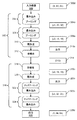
図2に示されるように、例えば、現在使用される方法200は、1024ピクセル×1024ピクセルのサイズを有する入力画像202を利用し得る。本方法は、入力画像202からパッチ画像のセット206を生成するクロッピング204を含み得、ここではパッチ画像の各々は、入力画像より大幅に小さくかつ本方法によって処理することができる最大サイズであるサイズを有する。例えば、クロッピング204は、各々が64ピクセル×64ピクセルのサイズを有する923,521枚のパッチ画像のセット206を生成し得る。それらのパッチ画像は、エンコーダ208およびエンコーダへの入力に相当する結果のセットを形成し得るデコーダ210を含むニューラルネットワークに入力され得る。例えば、上に説明されるパッチ画像のセットがエンコーダ208に入力される場合、デコーダ210は、各々が64ピクセル×64ピクセルのサイズを有する923,521枚のパッチ画像を含むパッチ画像のセット212を形成する。本方法は次いで、入力画像と同じサイズ(すなわち1024ピクセル×1024ピクセル)を有する最終画像結果216を生成するためにパッチ画像のセットを使用する再構築ステップ214を含み得る。
As shown in FIG. 2, for example, the
対照的に、本明細書に説明される実施形態は、入力画像に対していかなるクロッピングも実施せず、および/または入力画像より大きい画像に対して実施されるいかなるクロッピングによっても入力画像を生成しない。言い換えると、一旦入力画像が本明細書に説明される方法およびシステムに入力されると、その入力画像はクロッピングされない。加えて、本明細書に説明される実施形態において使用される入力画像は、より大きい画像からクロッピングされるのではない。本明細書に説明される実施形態はまた、本明細書に説明される実施形態の要素のいずれかによって生成された任意のより小さい画像から最終画像のいかなる再構築も実施しない。例えば、図2に示されるように、1つの実施形態218は、エンコーダ222およびデコーダ224を含むニューラルネットワークへの入力として入力画像220を利用し得る。エンコーダ222は、本明細書に説明される実施形態のいずれかに従って構成され得る2つ以上のエンコーダ層を含み得る。加えて、デコーダ224は、本明細書に説明される実施形態のいずれかに従って構成され得る2つ以上のデコーダ層を含み得る。
In contrast, the embodiments described herein do not perform any cropping on the input image and / or produce an input image by any cropping performed on an image larger than the input image. .. In other words, once the input image is input into the methods and systems described herein, the input image is not cropped. In addition, the input images used in the embodiments described herein are not cropped from larger images. The embodiments described herein also do not perform any reconstruction of the final image from any smaller image produced by any of the elements of the embodiments described herein. For example, as shown in FIG. 2, one
1つの実施形態において、本明細書にさらに説明されるように、ニューラルネットワークは、完全畳み込みニューラルネットワークとして構成され得、それは、各層タイプが特定の入力サイズに対して仮定を有さず、ネットワーク全体がトレーニングおよび推論の両方について任意サイズの入力に対して動作することができる構成を指す。加えて、ニューラルネットワークは、境界減衰を実施するために本明細書にさらに説明されるように構成され得る。デコーダは、入力画像と同じ画像サイズを有するシミュレーション画像226を形成するように構成され得る。例えば、入力画像サイズが1024ピクセル×1024ピクセルである場合、出力画像サイズは、1024ピクセル×1024ピクセルである。したがって、現在使用される方法200と実施形態218とを比較することによって示されるように、本明細書に説明される実施形態は、いかなるクロッピングおよび再構築ステップも実施しないように構成され得る。
In one embodiment, as further described herein, the neural network can be configured as a fully convolutional neural network, where each layer type makes no assumptions for a particular input size and the entire network. Refers to a configuration that can work on inputs of any size for both training and inference. In addition, neural networks can be configured as further described herein to perform boundary attenuation. The decoder may be configured to form a simulation image 226 with the same image size as the input image. For example, if the input image size is 1024 pixels x 1024 pixels, the output image size is 1024 pixels x 1024 pixels. Therefore, as shown by comparing the currently used
1つの実施形態において、1つ以上のコンピュータサブシステムは、前から存在するニューラルネットワーク内の全結合層を畳み込み層のグループで置き換え、それによりニューラルネットワークを作成することによって、ニューラルネットワークを設定するように構成されている。例えば、本明細書に説明される実施形態は、「Fully convolutional networks for semantic segmentation」、ロング(Long)ら、CVPR2015、pp.3431−3440,2015に説明される一般概念に従って、ニューラルネットワークの全結合層を畳み込み層で置き換えて、入力サイズに依存しない全ニューラルネットワークを作り得、これを本明細書に完全に明記されるかのように引用により援用する。本明細書に説明される実施形態は、この参照文献において説明されるようにさらに構成されてもよい。 In one embodiment, one or more computer subsystems set up the neural network by replacing the fully connected layers in the pre-existing neural network with a group of convolutional layers, thereby creating the neural network. It is configured in. For example, the embodiments described herein are "Full convolutional neural networks for semantic segmentation", Long et al., CVPR2015, pp. Is it possible to replace the fully connected layer of a neural network with a convolution layer to create an input size independent whole neural network according to the general concept described in 3431-3440, 2015, which is fully specified herein? It is used by quoting as follows. The embodiments described herein may be further configured as described in this reference.
図3aおよび図3bは、固定の入力サイズ(すなわち64ピクセル×64ピクセル)を有する現在使用されるエンコーダ−デコーダネットワークがどのように任意の入力サイズを可能にする完全畳み込みネットワークに変換され得るかを例証する。具体的には、図3aは、64ピクセル×64ピクセルの固定の入力サイズを有する現在使用されるニューラルネットワークを示し、図3bは、本明細書に説明される手法により任意の入力サイズを可能にするニューラルネットワークの1つの実施形態を示す。図3aおよび図3bにおいて、入力および出力次元は、数個のステージにおいて示され、各そのようなインスタンスにおいて、次元は(C,H,W)の形式を有し、ここでCはチャネルの数であり、Hは入力または出力の高さであり、Wは入力または出力の幅である。 3a and 3b show how a currently used encoder-decoder network with a fixed input size (ie 64 pixels x 64 pixels) can be transformed into a fully convolutional network that allows for any input size. Illustrate. Specifically, FIG. 3a shows a currently used neural network with a fixed input size of 64 pixels x 64 pixels, and FIG. 3b allows any input size by the techniques described herein. An embodiment of a neural network is shown. In FIGS. 3a and 3b, the input and output dimensions are shown in several stages, in each such instance the dimensions have the form (C, H, W), where C is the number of channels. , H is the height of the input or output, and W is the width of the input or output.
図3aに示されるように、入力画像300は、現在使用されるネットワークのエンコーダ部分302に入力され得る。入力画像の入力次元300dは、(1,64,64)である。エンコーダ部分302は、畳み込み層およびプーリング層の2つのセット304および306、再形成層310、ならびに全結合層312を含む。入力画像は、畳み込み層およびプーリング層のセット304に入力され、セット304が、畳み込み層およびプーリング層のセット306に入力される出力304o(c1,32,32)を生成する。セット306の出力306o(c2,16,16)は、再形成層310に入力され、再形成層310が出力310oを生成し、出力310oは、全結合層312に入力され、全結合層312が、現在使用されるネットワークのデコーダ部分に出力される表現314(512)を生成する。
As shown in FIG. 3a, the input image 300 may be input to the
現在使用されるネットワークのデコーダ部分316は、全結合層318、再形成層320、ならびに畳み込み層およびアッププーリング層のセット322および324を含む。表現314は、全結合層318に入力され、全結合層318が出力318o(c3,16,16)を形成する。出力318oは、再形成層320に入力され、再形成層320が出力320oを形成し、出力320oは、畳み込み層およびアッププーリング層のセット322に入力され、セット322が出力322o(c4,32,32)を形成する。出力322oは、畳み込み層およびアッププーリング層のセット324に入力され、セット324が出力326を形成し、出力326は、出力次元326d(1,64,64)を有し、かつニューラルネットワークの出力である。
The
対照的に、図3bに示されるように、入力画像328は、本明細書に説明される実施形態に従って構成されたニューラルネットワークのエンコーダ部分330に入力される。入力画像328は、(1,1024,1024)の入力次元328dを有する。エンコーダ部分330は、畳み込み層およびプーリング層のセット332および334、ならびに畳み込み層のセット336を含む。入力画像328は、畳み込み層およびプーリング層のセット332に入力され、セット332が出力332o(c1,512,512)を形成し、出力332oは、出力334o(c2,256,256)を形成する畳み込み層およびプーリング層のセット334に入力される。出力334oは、畳み込み層のセット336に入力され、セット336が表現338(512,241,241)を形成する。
In contrast, as shown in FIG. 3b, the input image 328 is input to the
表現338は、本ニューラルネットワーク実施形態のデコーダ部分340に入力される。デコーダ部分340は、畳み込み層のセット342、ならびに畳み込み層およびアッププーリング層のセット344および346を含む。表現338は、畳み込み層のセット342に入力され、セット342が出力342o(c3,256,256)を形成する。出力342oは、畳み込みおよびアッププーリング層のセット344に入力され、セット344が出力344o(c4,512,512)を形成する。出力344oは、畳み込みおよびアッププーリング層のセット346に入力され、セット346が出力348を形成し、出力348は、(1,1024,1024)の出力次元348dを有し、かつニューラルネットワークの出力である。
The
上に援用された参考文献においてロング(Long)らにより説明される方法およびシステムとは違って、本明細書に説明されるような畳み込み層での全結合層の置き換えは、全結合層および畳み込み層の一対一のマッピングに限定されない。本明細書に説明される実施形態の文脈において、「一対一のマッピング」は、1つの全結合層(または1つの全結合層+1つの再形成層)を1つの畳み込み層で置き換えることに関与する。しかしながら、そのような構成は、結果として生じる畳み込み層について、かなり大きいカーネルサイズをもたらし得る。例えば、(上と同じ表記に従って)再形成層への入力次元が(N,64,32,32)である場合、再形成層の出力(すなわち全結合層への入力)は、(N,64*32*32)であり、全結合層の出力が(N,256)であると仮定すると、再形成層および全結合層は、カーネルサイズ(64,256,32,32)を有する畳み込み層で置き換えることができる。 Unlike the methods and systems described by Long et al. In the references referenced above, the replacement of fully connected layers with convolution layers as described herein is fully connected layers and convolutions. It is not limited to one-to-one mapping of layers. In the context of the embodiments described herein, "one-to-one mapping" involves replacing one fully connected layer (or one fully connected layer + one cambium) with one convolution layer. .. However, such a configuration can result in a significantly larger kernel size for the resulting convolution layer. For example, if the input dimension to the cambium (according to the same notation as above) is (N, 64, 32, 32), then the output of the cambium (ie the input to the fully connected layer) is (N, 64). * 32 * 32), and assuming that the output of the fully connected layer is (N, 256), the cambium and the fully connected layer are convolutional layers having a kernel size (64,256,32,32). Can be replaced.
カーネル(64,256,32,32)内のHおよびW(すなわち32)は、実際的な選択(例えば、3または5または7または10未満)と比較してかなり大きいため、学習プロセスは非効率であり得る。したがって、比較的大きいカーネルを有する畳み込み層は、比較的小さいカーネルを有する畳み込み層のグループによって近似され得る。例えば、上に提供された例では、(64,256,32,32)は、(64,M,32,1)および(M,256,1,32)で置き換えられ得、ここでMはフリーハイパーパラメータである。 The learning process is inefficient because the H and W (ie 32) in the kernel (64,256,32,32) are significantly larger than the practical choices (eg less than 3 or 5 or 7 or 10). Can be. Therefore, a convolution layer with a relatively large kernel can be approximated by a group of convolution layers with a relatively small kernel. For example, in the example provided above, (64,256,32,32) can be replaced by (64, M, 32,1) and (M, 256,1,32), where M is free. It is a hyperparameter.
そのようなグループ置き換えは、畳み込み層のグループを適用することの出力次元が、カーネル(C,O,H,W)を有する元の畳み込み層を適用することの出力次元と同じであるように、要求され得る。畳み込み層のグループの共通選択は、(C,O,H,W)==>(C,M,H,k)+(M,O,k,W)または(C,M,k,H)+(M,O,W,k)であり得、ここでkおよびMはハイパーパラメータであり、kは多くの場合かなり小さく(例えば、1,2,3,…)、かつHまたはWよりもはるかに小さい。 Such group replacement is such that the output dimension of applying a group of convolution layers is the same as the output dimension of applying the original convolution layer with kernels (C, O, H, W). Can be requested. The common selection of convolutional layer groups is (C, O, H, W) ==> (C, M, H, k) + (M, O, k, W) or (C, M, k, H). Can be + (M, O, W, k), where k and M are hyperparameters, where k is often much smaller (eg 1, 2, 3, ...) and less than H or W. Much smaller.
全結合層のウィンドウサイズが半導体プロセス条件(例えば、リソグラフィツールおよび/もしくは光学検査ツールの点広がり関数、またはエッチングプロセスにおける化学的および物理的反応など)を考慮するために十分に大きいとき、全結合層は、本明細書に説明されるように畳み込み層のグループ(各々がより小さいフィルタウィンドウサイズ(HおよびWにおいて)を有する)で置き換えられ得、グループ全体の効果的なウィンドウサイズは、全結合層におけるサイズと同一であるか、またはそれより大きい。本手法は、入力サイズ制約を取り除き、また、(トレーニングおよびランタイムの両方について)パラメータの総数を低減する。この様式では、本明細書に説明される実施形態は、畳み込み層のグループを使用して、モデルサイズを低減すると同時に半導体プロセスに起因するウィンドウサイズを満足し得る。 Fully coupled when the window size of the fully coupled layer is large enough to take into account semiconductor process conditions (eg, the point spread function of lithography and / or optical inspection tools, or chemical and physical reactions in the etching process). Layers can be replaced by groups of convolutional layers, each with a smaller filter window size (in H and W) as described herein, and the effective window size of the entire group is fully coupled. Equal to or greater than the size in the layer. The technique removes input size constraints and also reduces the total number of parameters (for both training and runtime). In this manner, the embodiments described herein may use a group of convolution layers to reduce the model size while at the same time satisfying the window size due to the semiconductor process.
いくつかの実施形態において、2つ以上のエンコーダ層に入力される画像は、標本のために生成された全体フレーム画像である。「フレーム」画像という用語は、概して、ウェハまたはレチクルなどの標本の走査の最中に取得された一筋のデータまたは画像におけるダイの一部分についてのデータまたは画像と、本明細書では定義される。「フレーム」または「ジョブ」はまた、概して、システムによってユニットとしてまとめて処理され得る、撮像サブシステムによって生成された出力のすべてのうちの比較的小さい部分と定義され得る。したがって、出力の「フレーム」は、撮像サブシステム構成、ならびに撮像サブシステムによって生成された出力を取り扱うおよび/または処理するためにシステムに含まれる任意の構成要素の構成によって異なり得る。しかしながら、画像フレームは、概して、パッチ画像、および画像をシミュレートするために現在使用されるニューラルネットワークに典型的に入力され得る最大画像サイズよりも大幅に大きくなる。例えば、本明細書に説明される実施形態のための画像フレームは、1024ピクセル×1024ピクセルまたは512ピクセル×512ピクセルであり得るが、パッチ画像は、64ピクセル×64ピクセルまたは32ピクセル×32ピクセルの典型的サイズを有し得る。 In some embodiments, the image input to the two or more encoder layers is a full frame image generated for the sample. The term "frame" image is generally defined herein as a line of data or image about a portion of a die in a line of data or image acquired during scanning of a specimen such as a wafer or reticle. A "frame" or "job" can also be generally defined as a relatively small portion of all of the output produced by the imaging subsystem that can be processed together as a unit by the system. Thus, the "frame" of the output may vary depending on the imaging subsystem configuration and the configuration of any component included in the system to handle and / or process the output produced by the imaging subsystem. However, the image frame is generally significantly larger than the patch image and the maximum image size that can be typically input to the neural networks currently used to simulate the image. For example, the image frame for the embodiments described herein can be 1024 pixels x 1024 pixels or 512 pixels x 512 pixels, while the patch image is 64 pixels x 64 pixels or 32 pixels x 32 pixels. Can have a typical size.
別の実施形態において、2つ以上のエンコーダ層に入力される画像は、標本のための全体ダイ画像である。例えば、全体ダイ画像は、撮像システムによって標本上のダイのために生成された画像データまたは出力のすべてを含み得る。この様式では、現在使用されるニューラルネットワークとは違って、本明細書に説明される実施形態は、実際に全体フレームまたは全体ダイレンダリングを可能にする。具体的には、本明細書に説明される実施形態は、全結合層をニューラルネットワークのための畳み込み層で置き換え、それにより任意の画像サイズを可能にする。この様式では、本明細書に説明される実施形態は、ニューラルネットワークユースケースについて全体フレームおよびダイランタイム予測を可能にする。 In another embodiment, the image input to the two or more encoder layers is a whole die image for the specimen. For example, the entire die image may include all of the image data or output generated for the die on the specimen by the imaging system. In this manner, unlike the neural networks currently used, the embodiments described herein actually allow whole frame or whole die rendering. Specifically, the embodiments described herein replace the fully connected layer with a convolution layer for the neural network, thereby allowing any image size. In this manner, the embodiments described herein allow for whole frame and die-runtime predictions for neural network use cases.
したがって、本明細書に説明される実施形態は、シミュレーション画像を生成するための他の方法およびシステムに勝るいくつかの利点を有する。例えば、本明細書に説明される実施形態は、トレーニングおよびランタイムについて任意の入力サイズを可能にする。加えて、本明細書に説明される実施形態は、現在使用される方法およびシステムと比較して100倍から1000倍、ランタイム計算を大いに減少させる。したがって、本明細書に説明される実施形態は、現在使用される方法およびシステムと比較してランタイムハードウェアコストを減少させる。加えて、本実施形態は、全体フレームおよびダイ予測を可能にする。さらには、本明細書に説明される実施形態は、有利には、同じ動作ウィンドウサイズを保ちながらモデルサイズ(すなわち、モデルパラメータの数)を減少させる。この様式では、本明細書に説明される実施形態は、トレーニングプロセスにおける通信過負荷を減少させる。さらに、本明細書に説明される実施形態に相当するパフォーマンスを有する代替の方法はない。 Therefore, the embodiments described herein have some advantages over other methods and systems for generating simulated images. For example, the embodiments described herein allow for any input size for training and runtime. In addition, the embodiments described herein significantly reduce run-time calculations by 100 to 1000 times compared to currently used methods and systems. Therefore, the embodiments described herein reduce run-time hardware costs as compared to currently used methods and systems. In addition, the present embodiment allows for overall frame and die prediction. Moreover, the embodiments described herein advantageously reduce the model size (ie, the number of model parameters) while maintaining the same operating window size. In this manner, the embodiments described herein reduce communication overload in the training process. Moreover, there is no alternative method with performance equivalent to the embodiments described herein.
本明細書に説明される実施形態は、ニューラルネットワークをトレーニングするように構成されている場合とそうでない場合とがある。例えば、別の方法および/またはシステムが、トレーニングされたニューラルネットワークを生成するように構成され得、その後このニューラルネットワークは、本明細書に説明される実施形態によってアクセスされかつ使用され得る。 The embodiments described herein may or may not be configured to train a neural network. For example, another method and / or system may be configured to generate a trained neural network, which may then be accessed and used by the embodiments described herein.
1つの実施形態において、1つ以上のコンピュータサブシステムは、境界効果を変更するためにfovy減衰重み付け損失関数を使用してニューラルネットワークをトレーニングするように構成されている。例えば、エンコーダおよびデコーダトポロジならびにエンコーダおよびデコーダにおける畳み込みタイプ(例えば、valid、full、same)に応じて、出力の境界部に対して、ニューラルネットワークが比較的深く、トレーニング画像が比較的小さいときは特に、畳み込み層の境界効果に起因して、出力の中心部と比較して異なる数学演算が行われ得る。具体的には、畳み込み層は、VALID、SAME、およびFULLの3つのパディングタイプを有する。入力画像サイズが(H,W)で畳み込みフィルタサイズが(h,w)の場合、(a)VALIDからの出力サイズは(H−h+1,W−w+1)、(b)SAMEからの出力サイズは(H,w)、および(c)FULLからの出力サイズは(H+h−1,W+w−1)である。SAMEまたはFULLパディングが使用される場合、入力画像の境界部において、畳み込みフィルタは、画像の外側に置かれ、それは、入力画像の外側のピクセルをゼロ値と見なすことに相当する。これは、画像の境界における畳み込み結果が多くの場合代表的ではないことを意味し、アーチファクト結果は境界において明らかになり得る。 In one embodiment, one or more computer subsystems are configured to train a neural network using a fooy attenuation weighted loss function to change the boundary effect. For example, depending on the encoder and decoder topology and the convolution type in the encoder and decoder (eg, valid, full, same), especially when the neural network is relatively deep and the training image is relatively small with respect to the output boundaries. Due to the boundary effect of the convolutional layer, different mathematical operations can be performed compared to the center of the output. Specifically, the convolutional layer has three padding types: VALID, SAME, and FULL. When the input image size is (H, W) and the convolution filter size is (h, w), (a) the output size from VALUE is (H-h + 1, W-w + 1), and (b) the output size from SAME is. The output sizes from (H, w) and (c) FULL are (H + h-1, W + w-1). When SAME or FULL padding is used, at the boundaries of the input image, the convolution filter is placed outside the image, which corresponds to considering the pixels outside the input image as zero values. This means that the convolution results at the boundaries of the image are often atypical, and the artifact results can be apparent at the boundaries.
境界領域の寄与を取り除くために、fovy減衰重み付け損失関数がトレーニングプロセス中に使用され得、ここで「fovy」とは、y方向における視野を指すために共通して使用される(OpenGLなどのグラフィックアプリケーションにおいて使用されるように)。例えば、完全畳み込みネットワークをSAMEまたはFULLパディングを用いてトレーニングするとき、トレーニングは、境界ピクセルにおける結果を考慮し、これが学習プロセスにアーチファクトからの多くのノイズをもたらす。この問題に対処するため、fovy減衰重み付け損失関数、例えば、3×3 fovy
0.5,0.6,0.5
0.6,1.0,0.6
0.5,0.6,0.5
が導入され得、ここで中央領域は1.0に近いかまたはそれに等しい重みを有し、境界領域近くでは、その値は1.0未満である。fovy減衰重み付け損失の動機は、学習プロセスに、比較的中央領域のピクセルに焦点を合わせさせることである。
To remove the contribution of the boundary region, a fooy attenuation weighted loss function can be used during the training process, where "favy" is commonly used to refer to the field of view in the y direction (graphics such as OpenGL). As used in the application). For example, when training a fully convolutional network with SAME or FULL padding, the training takes into account the results at the boundary pixels, which brings a lot of noise from the artifacts to the learning process. To address this issue, a fovy attenuation weighted loss function, such as a 3x3 fovy
0.5, 0.6, 0.5
0.6, 1.0, 0.6
0.5, 0.6, 0.5
Can be introduced, where the central region has a weight close to or equal to 1.0, and near the boundary region its value is less than 1.0. The motive for the force attenuation weighting loss is to have the learning process focus on the pixels in the relatively central region.
減衰の形状は、エンコーダおよびデコーダトポロジならびに関連用途に応じて、円形、正方形、または長方形であり得る。加えて、fovy減衰重みを生成する共通方式は、(1)固定の比較的小さい値を一定の境界線に、および1.0の左中央領域を割り当てること(2)正しく選択された平均値および標準偏差を伴う2Dガウスカーネル、ならびに(3)正しく選択された平均値および標準偏差を伴う2つの1Dガウスカーネルである。いくつかの用途では、このステップは省略されてもよい。この様式では、本明細書に説明される実施形態は、fovy減衰重み付け損失関数を使用してトレーニングにおける望ましくない境界効果(または境界ノイズ)を取り除くことができる。 The shape of the attenuation can be circular, square, or rectangular, depending on the encoder and decoder topologies and related applications. In addition, a common method of generating fooy attenuation weights is to (1) assign a fixed, relatively small value to a constant boundary, and allocate 1.0 to the left center region (2) a correctly selected mean and A 2D Gaussian kernel with standard deviation, and (3) two 1D Gaussian kernels with properly selected mean and standard deviation. For some applications, this step may be omitted. In this manner, the embodiments described herein can use the fooy attenuation weighted loss function to remove unwanted boundary effects (or boundary noise) in training.
一般に、ニューラルネットワークをトレーニングすることは、データ(例えば、入力画像およびシミュレーション画像の両方であり、本明細書に説明される入力画像およびシミュレーション画像のいずれかを含み得るデータ)を取得することを含む。1つの実施形態において、1つ以上のコンピュータサブシステムは、各々が同じ任意サイズを有するトレーニング画像のバッチを使用してニューラルネットワークをトレーニングするように構成されている。追加の実施形態において、1つ以上のコンピュータサブシステムは、トレーニング画像のバッチを使用してニューラルネットワークをトレーニングするように構成され、バッチ内のトレーニング画像のうちの2つ以上は、異なる任意サイズを有する。この様式では、任意サイズの画像のバッチは、複数サイズの画像を含み得るか、または各バッチは、すべて同じ任意サイズの画像を含み得る。実際には、計算および実装の効率性のため、各バッチは、すべて同じ任意サイズの画像を含み得る。 In general, training a neural network involves acquiring data (eg, both input and simulation images, which may include any of the input and simulation images described herein). .. In one embodiment, one or more computer subsystems are configured to train a neural network using batches of training images, each of which has the same arbitrary size. In additional embodiments, one or more computer subsystems are configured to use a batch of training images to train a neural network, and two or more of the training images in the batch have different arbitrary sizes. Have. In this format, batches of arbitrary size images may contain multiple size images, or each batch may all contain the same arbitrary size image. In practice, for computational and implementation efficiency, each batch may all contain the same arbitrary size image.
ニューラルネットワークをトレーニングするために使用される画像は、入力画像と同じサイズを有する場合とそうでない場合とがある。例えば、入力画像は、ネットワークトポロジに起因して最小サイズ要件を有し得、それがハードウェア格納制限に合う限りは最小限のサイズ制限を有しない。最小サイズは、ネットワークトポロジによって決定され得、多くの場合、光学設定を反映するように選択される。実際には、パッチ画像は、多くの場合、最小サイズ要件よりも大きい。実際には、(1)パッチ画像に対してトレーニングして、パッチまたはフレーム画像に対して予測をするか、または(2)フレーム画像に対してトレーニングをして、パッチまたはフレーム画像に対して予測をすることができる。 The image used to train the neural network may or may not have the same size as the input image. For example, the input image may have a minimum size requirement due to the network topology and does not have a minimum size limit as long as it meets the hardware storage limit. The minimum size can be determined by the network topology and is often chosen to reflect the optical settings. In practice, patch images are often larger than the minimum size requirement. In practice, either (1) train the patch image and make predictions for the patch or frame image, or (2) train the frame image and make predictions for the patch or frame image. Can be done.
いくつかのそのような実施形態において、任意サイズのトレーニング画像(それらの各々は、設計された最小限サイズ、すなわち図3aに示される例においては64ピクセル×64ピクセル以上であり得る)のセットを前提として、トレーニングステップでは、画像のランダムバッチが選択される。トレーニングは、サブステップなしの1つのステップで実施され得る。加えて、トレーニングデータを準備するために必要とされる追加のステップは存在しない。理論上、任意サイズの画像のバッチが、トレーニングのために使用され得る。しかしながら、ハードウェア低水準命令を活用するために、固定サイズのパッチのバッチが、選択された画像からランダムにサンプリングされ得る。これらのサンプリングされたパッチ画像は、トレーニングステップのために使用され得る。パッチサイズは、トレーニングステップでは異なり得るが、一般的にはそれは事前に決められる。次いでランタイムにおいて、任意サイズのランタイム画像のセットを前提として、それらの各々が、クロッピングまたは再構築ステップなしに予測(すなわちシミュレーション画像)を生成するためにネットワークに供給され得る。 In some such embodiments, a set of training images of arbitrary size, each of which can be the minimum size designed, ie 64 pixels x 64 pixels or more in the example shown in FIG. 3a. As a premise, a random batch of images is selected in the training step. Training can be performed in one step without substeps. In addition, there are no additional steps required to prepare the training data. In theory, a batch of images of any size could be used for training. However, to take advantage of low-level hardware instructions, batches of fixed-size patches can be randomly sampled from selected images. These sampled patch images can be used for training steps. Patch size can vary during training steps, but is generally pre-determined. Then, at runtime, given a set of runtime images of arbitrary size, each of them can be fed to the network to generate predictions (ie, simulation images) without cropping or reconstruction steps.
モデルをトレーニングすることは、2016年6月7日出願のチャン(Zhang)らによる米国特許出願第15/176,139号、および2016年12月29日出願のバスカー(Bhaskar)らによる同第15/394,790号に説明されるようにさらに実施され得、これらを本明細書に完全に明記されるかのように引用により援用する。本明細書に説明される実施形態は、これらの特許出願に説明されるようにさらに構成されてもよい。 Training the model includes US Patent Application No. 15 / 176,139 by Zhang et al., Filed June 7, 2016, and Baskar et al., Filed December 29, 2016. It may be further implemented as described in / 394,790, which is incorporated by reference as if fully specified herein. The embodiments described herein may be further configured as described in these patent applications.
エンコーダ層によって決定された特徴部は、当該技術分野において知られる任意の好適な特徴部を含み得、それは入力から推論することができ、本明細書にさらに説明される出力を生成するために使用される。例えば、特徴部は、ピクセルあたりの強度値のベクトルを含み得る。特徴部はまた、本明細書に説明される任意の他のタイプの特徴部、例えば、スカラ値のベクトル、独立分布のベクトル、同時分布、または当該技術分野において知られる任意の好適な特徴部タイプを含み得る。 The feature determined by the encoder layer may include any suitable feature known in the art, which can be inferred from the input and used to produce the output further described herein. Will be done. For example, the feature may include a vector of intensity values per pixel. Features may also be any other type of feature described herein, such as a vector of scalar values, an independent distribution vector, a joint distribution, or any suitable feature type known in the art. Can include.
上記のニューラルネットワークの層の各々は、重みWおよびバイアスBなどの1つ以上のパラメータを有し得、それらの値は、ニューラルネットワークをトレーニングすることによって決定することができ、このトレーニングは本明細書にさらに説明されるように実施され得る。例えば、ニューラルネットワークに含まれる任意の層の重みおよびバイアスは、費用関数を最小限にすることによってトレーニング中に決定され得る。費用関数は、画像に対して実施されている変換によって異なり得る。 Each layer of the neural network described above may have one or more parameters such as weight W and bias B, the values of which can be determined by training the neural network, which training is described herein. It can be carried out as further described in the book. For example, the weights and biases of any layer contained in a neural network can be determined during training by minimizing the cost function. The cost function can vary depending on the transformations performed on the image.
本明細書に説明されるニューラルネットワークは、特定の標本(例えば、特定のウェハまたはレチクル)、プロセス、および撮像パラメータのために生成され得る。言い換えると、本明細書に説明されるニューラルネットワークは、標本特有、プロセス特有、および撮像パラメータ特有であり得る。例えば、1つの実施形態において、各ニューラルネットワークは、特定の設計およびウェハ層に特有であるようにトレーニングされ得る。次いで、トレーニングされたニューラルネットワークは、その層の予測を実施するためだけに使用されることになる。この様式では、異なるウェハ層に対しては異なるニューラルネットワークが生成され得る。しかしながら、別の実施形態において、単一のニューラルネットワークが、異なる設計およびウェハタイプ層からのデータを用いてトレーニングされ得る。結果として生じるニューラルネットワークは、トレーニングデータに含まれるすべてのタイプの標本のために概して予測を実施するために使用され得る。加えて、異なるニューラルネットワークが、入力画像を生成するために使用される撮像パラメータの異なるセット(例えば、異なる撮像モード)に対して、およびおそらくは、変換が実施されるシミュレーション画像の撮像パラメータの異なるセット(例えば、異なる撮像モード)に対して(例えば、異なる撮像モードに対応する複数のシミュレーション画像を生成する場合)生成され得る。一般に、ニューラルネットワークは、選択された撮像モードがツールにわたって繰り返し可能である限りはツールとは無関係であり得る。異なるニューラルネットワークの各々は、異なるトレーニングデータセットを用いて生成され得る。異なるトレーニングデータセットの各々は、任意の好適な様式で生成され得る。 The neural networks described herein can be generated for a particular sample (eg, a particular wafer or reticle), process, and imaging parameters. In other words, the neural networks described herein can be sample-specific, process-specific, and imaging parameter-specific. For example, in one embodiment, each neural network can be trained to be specific to a particular design and wafer layer. The trained neural network will then be used only to make predictions for that layer. In this mode, different neural networks can be generated for different wafer layers. However, in another embodiment, a single neural network can be trained with data from different design and wafer type layers. The resulting neural network can generally be used to make predictions for all types of samples contained in the training data. In addition, different neural networks are used for different sets of imaging parameters (eg, different imaging modes) used to generate the input images, and possibly different sets of imaging parameters for the simulated image in which the transformation is performed. It can be generated for (eg, different imaging modes) (eg, when generating multiple simulation images corresponding to different imaging modes). In general, neural networks can be tool-independent as long as the selected imaging mode is repeatable across the tool. Each of the different neural networks can be generated using different training datasets. Each of the different training datasets can be generated in any suitable fashion.
本明細書に説明される実施形態は、いくつかの異なるタイプの変換(すなわち入力画像を1つ以上のシミュレーション画像に変換すること)を実施するように構成され得る。例えば、いくつかの実施形態において、ニューラルネットワークは、低解像度入力画像から1つ以上の高解像度画像を生成するように構成され得る。標本の「低解像度画像」という用語は、本明細書で使用される場合、概して、画像が生成された標本の領域内に形成されるパターン化特徴部のすべてが画像内に解像されない画像と定義される。例えば、低解像度画像が生成された標本の領域内のパターン化特徴部は、それらのサイズがそれらを解像可能にするのに十分に大きい場合に低解像度画像内に解像され得る。しかしながら、低解像度画像は、画像内のすべてのパターン化特徴部を解像可能にする解像度で生成されない。この様式では、「低解像度画像」は、その用語が本明細書で使用される場合、欠陥分類および/または検証を含み得る欠陥レビューならびに計測などの用途に使用されるべき低解像度画像に十分である標本上のパターン化特徴部に関する情報を含まない。加えて、「低解像度画像」は、その用語が本明細書で使用される場合、概して、典型的には、比較的高速のスループットを有するために比較的より低い(例えば、欠陥レビューおよび/または計測システムよりも低い)解像度を有する、検査システムによって生成された画像を指す。 The embodiments described herein can be configured to perform several different types of transformations (ie, transforming an input image into one or more simulation images). For example, in some embodiments, the neural network may be configured to generate one or more high resolution images from the low resolution input images. The term "low resolution image" of a specimen, as used herein, generally refers to an image in which all of the patterned features formed within the region of the specimen from which the image was generated are not resolved in the image. Defined. For example, patterned features within the region of the specimen from which the low resolution image was generated can be resolved within the low resolution image if their size is large enough to make them resolvable. However, low resolution images are not generated at a resolution that allows resolution of all patterned features in the image. In this form, "low resolution image" is sufficient for low resolution images to be used for applications such as defect review and measurement, which, when the term is used herein, may include defect classification and / or verification. Does not contain information about patterned features on a sample. In addition, "low resolution image", when the term is used herein, is generally relatively lower (eg, defect review and / or) to have relatively fast throughput. Refers to an image produced by an inspection system that has a resolution (lower than the measurement system).
「低解像度画像」はまた、それらが本明細書に説明される「高解像度画像」よりも低い解像度を有するという点で「低解像度」であり得る。「高解像度画像」は、その用語が本明細書で使用される場合、概して、標本のすべてのパターン化特徴部が比較的高い精度で解像される画像と定義され得る。この様式では、高解像度画像が生成される標本の領域内のパターン化特徴部のすべてが、それらのサイズにかかわらず高解像度画像内に解像される。そのようなものとして、「高解像度画像」は、その用語が本明細書で使用される場合、欠陥分類および/または検証を含み得る欠陥レビューならびに計測などの用途に使用されるべき高解像度画像に十分である標本のパターン化特徴部に関する情報を含む。加えて、「高解像度画像」は、その用語が本明細書で使用される場合、概して、増大されたスループットのために解像能力を犠牲にするように構成されているルーチン動作中の検査システムによって作成することができない画像を指す。 "Low resolution images" can also be "low resolution" in that they have a lower resolution than the "high resolution images" described herein. A "high resolution image", as the term is used herein, can generally be defined as an image in which all patterned features of a specimen are resolved with relatively high accuracy. In this mode, all of the patterned features in the area of the specimen from which the high resolution image is generated are resolved in the high resolution image regardless of their size. As such, "high resolution image" is a high resolution image to be used for applications such as defect review and measurement, which, when the term is used herein, may include defect classification and / or verification. Contains information about the patterning features of the specimen that are sufficient. In addition, "high resolution image", as the term is used herein, is a routine in-service inspection system that is generally configured to sacrifice resolution for increased throughput. Refers to an image that cannot be created by.
低解像度画像はまた、例えば、標本の光学画像を含み得、高解像度画像は、標本のための電子ビーム画像(例えば、走査電子顕微鏡(SEM)画像)または設計データを含み得る。加えて、本明細書にさらに説明されるように、標本のための高解像度画像は、本明細書に説明されるように構成されたニューラルネットワークを用いて生成され得る。したがって、本明細書にさらに説明されるように、本実施形態は、深層学習技術を使用して光学からSEMおよび/または設計へのデータ変換を実施するように構成され得る。 The low resolution image may also include, for example, an optical image of the specimen, and the high resolution image may include an electron beam image for the specimen (eg, a scanning electron microscope (SEM) image) or design data. In addition, as further described herein, high resolution images for specimens can be generated using neural networks configured as described herein. Therefore, as further described herein, this embodiment may be configured to perform data conversion from optics to SEM and / or design using deep learning techniques.
本明細書に説明される実施形態は、1つ以上のシミュレーション画像を、おそらくは入力画像と組み合わせて使用して、いくつかの異なる機能を実施するように構成され得る。例えば、1つ以上のコンピュータサブシステムは、(a)光学、電子ビーム、およびマスクツール上のIC構造の表現学習、(b)欠陥検出および分類、ならびに(c)全体フレームまたはダイ検査のために構成され得る。これらの機能の各々は、本明細書にさらに説明されるように実施されてもよい。 The embodiments described herein may be configured to use one or more simulation images, perhaps in combination with an input image, to perform several different functions. For example, one or more computer subsystems are used for (a) feature learning of IC structures on optics, electron beams, and mask tools, (b) defect detection and classification, and (c) whole frame or die inspection. Can be configured. Each of these functions may be performed as further described herein.
1つの実施形態において、1つ以上のコンピュータサブシステムは、2つ以上のエンコーダ層に入力される画像または1つ以上のシミュレーション画像内で検出された欠陥を分類するように構成されており、分類は、1つ以上のシミュレーション画像に基づいて実施される。例えば、ニューラルネットワークへの入力画像は、標本の光学画像であり得、ニューラルネットワークによって生成された1つ以上のシミュレーション画像は、電子ビーム撮像サブシステムによって生成され得る画像および/または標本のための設計データもしくは設計情報の画像などの標本の高解像度画像を含み得る。 In one embodiment, one or more computer subsystems are configured to classify defects detected in images input to two or more encoder layers or in one or more simulation images. Is performed based on one or more simulation images. For example, the input image to the neural network can be an optical image of the sample, and one or more simulation images generated by the neural network can be the image and / or design for the sample that can be generated by the electron beam imaging subsystem. It can include high resolution images of the specimen, such as images of data or design information.
光学画像からSEMおよび/または設計への変換の1つの利益は、光学検査が依然として、半導体製造プロセスにおける大量生産歩留りのための鍵であるということである。解像度の欠如に起因して、光学インスペクタによって検出される欠陥は、欠陥分類のためにSEMレビューを必要とする。光学をSEMおよび/または設計に自動的に変換する方法は、潜在的には、歩留り管理のためのSEMレビュー要件を低減し、それにより合計検査サイクル時間を減少させることができる。例えば、本明細書に説明される実施形態は、本明細書に説明されるシミュレーション画像が1)標本なしおよび撮像ハードウェアなしで取得され得、2)欠陥分類などの欠陥レビュー用途のために使用され得ることから、標本検査後に欠陥レビューシステム上でSEM画像を取得する必要性を除去することができる。 One benefit of the conversion of optical images to SEM and / or design is that optical inspection is still the key to mass production yields in semiconductor manufacturing processes. Defects detected by the Optical Inspector due to lack of resolution require SEM review for defect classification. The method of automatically converting optics to SEM and / or design can potentially reduce the SEM review requirements for yield management, thereby reducing the total inspection cycle time. For example, the embodiments described herein can be used for defect review applications such as 1) no specimens and no imaging hardware, and 2) defect classification and other simulation images described herein. It is possible to eliminate the need to acquire SEM images on the defect review system after sample inspection.
ニューラルネットワークによって分類される欠陥は、本明細書に説明される入力画像および/または1つ以上のシミュレーション画像内で検出され得る。加えて、1つ以上のシミュレーション画像に基づいて欠陥を分類することは、当該技術分野で知られている任意の好適な様式で実施され得る。例えば、1つ以上のシミュレーション画像は、当該技術分野で知られている任意の好適な欠陥分類方法および/またはアルゴリズムへの入力として使用され得る。言い換えると、1つ以上のシミュレーション画像は、欠陥分類のための任意の他の画像として使用され得る。本明細書に説明される実施形態によって実施される欠陥分類の結果は、任意の好適な形式(例えば、欠陥分類コードなど)を有し得る。 Defects classified by the neural network can be detected in the input images and / or one or more simulation images described herein. In addition, classifying defects based on one or more simulation images can be performed in any suitable manner known in the art. For example, one or more simulation images can be used as input to any suitable defect classification method and / or algorithm known in the art. In other words, one or more simulation images can be used as any other image for defect classification. The results of defect classification performed by the embodiments described herein can have any suitable form (eg, defect classification code, etc.).
さらなる実施形態において、1つ以上のコンピュータサブシステムは、1つ以上のシミュレーション画像に基づいて標本上の欠陥を検出するように構成されている。コンピュータサブシステムは、1つ以上のシミュレーション画像を使用して任意の好適な様式で標本上の欠陥を検出するように構成され得る。例えば、コンピュータサブシステムは、1つ以上の欠陥検出アルゴリズムおよび/または方法を1つ以上のシミュレーション画像に適用するように構成され得、それは当該技術分野で知られている任意の好適な欠陥検出アルゴリズムおよび/または方法を含み得る。1つのそのような例において、コンピュータサブシステムは、1つ以上のシミュレーション画像を標本のための基準と比較し、次いでその比較の結果にしきい値を適用するように構成され得る。しきい値を上回る比較の結果を有するシミュレーション画像内のピクセルは、欠陥として識別され得る一方、しきい値を下回る比較の結果を有するシミュレーション画像内のピクセルは、欠陥として識別され得ない。 In a further embodiment, one or more computer subsystems are configured to detect defects on the specimen based on one or more simulation images. The computer subsystem can be configured to detect defects on the specimen in any suitable manner using one or more simulation images. For example, a computer subsystem may be configured to apply one or more defect detection algorithms and / or methods to one or more simulation images, which is any suitable defect detection algorithm known in the art. And / or methods may be included. In one such example, the computer subsystem may be configured to compare one or more simulated images with a reference for the sample and then apply a threshold to the result of that comparison. Pixels in a simulated image with a comparison result above the threshold can be identified as defects, while pixels in a simulation image with a comparison result below the threshold cannot be identified as defects.
別の例において、コンピュータサブシステムは、2016年11月16日出願のカーセンティ(Karsenti)らによる米国特許出願第15/353,210号に説明されるように、単一の画像検出のために構成され得、これを本明細書に完全に明記されるかのように引用により援用する。1つのそのような実施形態において、この特許出願に説明されるように、ニューラルネットワークによって入力画像のために決定された特徴部は、入力画像内の欠陥を検出するために使用され得る。例えば、コンピュータサブシステムは、入力画像内のピクセルまたはピクセルのブロックのためのラベルを、(1)決定された特徴部、および(2)入力特徴部マップボリュームのピクセルまたはピクセルのブロックの、ラベルへのマッピングに基づいて選択するように構成され得る。コンピュータサブシステムは、ピクセルまたはブロックのための選択されたラベルに基づいて標本上の欠陥を検出するようにさらに構成され得る。 In another example, the computer subsystem is for single image detection, as described in US Patent Application No. 15 / 353,210 by Karsenti et al., Filed November 16, 2016. It may be constructed and incorporated by reference as if fully specified herein. In one such embodiment, as described in this patent application, the features determined for the input image by the neural network can be used to detect defects in the input image. For example, the computer subsystem may label a pixel or block of pixels in the input image to (1) a determined feature and (2) a block of pixels or pixels in the input feature map volume. Can be configured to select based on the mapping of. The computer subsystem may be further configured to detect defects on the specimen based on the selected label for pixels or blocks.
加えて、コンピュータサブシステムは、ニューラルネットワークによって生成される1つ以上のシミュレーション画像と組み合わせてニューラルネットワークへ入力される画像を使用して、標本上の欠陥を検出するように構成され得る。例えば、入力画像が低解像度画像でありかつ1つ以上のシミュレーション画像が高解像度画像を含む場合、低解像度画像内で検出された欠陥の位置は、欠陥の設計コンテキストを決定するために高解像度画像内で識別され得、次いでそれを、欠陥が不快な欠陥または実欠陥であるかどうかを決定するために使用することができる。加えて、低解像度画像内で検出された欠陥の位置は、高解像度画像内のその欠陥の位置を識別して、その欠陥が高解像度画像内に存在する(検出され得る)かどうかを決定するために使用され得る。高解像度画像内でその欠陥を検出することができる場合、それは実欠陥と指定される。高解像度画像内でその欠陥を検出することができない場合、それは有害な欠陥と指定される。 In addition, the computer subsystem can be configured to detect defects on the sample using images input to the neural network in combination with one or more simulation images generated by the neural network. For example, if the input image is a low resolution image and one or more simulation images include a high resolution image, the location of the defects detected within the low resolution image is a high resolution image to determine the design context of the defect. It can be identified within and then it can be used to determine if the defect is an unpleasant or actual defect. In addition, the location of the defect detected in the low resolution image identifies the location of the defect in the high resolution image and determines if the defect is (can be detected) in the high resolution image. Can be used for. If the defect can be detected in a high resolution image, it is designated as a real defect. If the defect cannot be detected in the high resolution image, it is designated as a harmful defect.
追加の実施形態において、1つ以上のコンピュータサブシステムは、標本の1つ以上の特徴部、または1つ以上のシミュレーション画像に基づいて標本上で検出された欠陥を測定するように構成されている。例えば、ニューラルネットワークは、ニューラルネットワークによって生成された1つ以上のシミュレーション画像が、低解像度画像である入力画像から生成された高解像度画像であるように構成され得る。したがって、高解像度画像は、標本上に形成された特徴部(例えば、線、空間、接点などのパターン化特徴部、ならびに標本上の欠陥)に関して入力画像よりも詳細を含み得る。次いで、コンピュータサブシステムがこれらの高解像度画像を使用して、標本上の特徴部のうちの1つ以上の特徴を測定または決定し得る。 In additional embodiments, one or more computer subsystems are configured to measure defects detected on a sample based on one or more features of the sample, or one or more simulation images. .. For example, a neural network may be configured such that one or more simulation images generated by the neural network are high resolution images generated from input images that are low resolution images. Therefore, a high resolution image may contain more detail than the input image with respect to features formed on the sample (eg, patterned features such as lines, spaces, contacts, and defects on the sample). The computer subsystem can then use these high resolution images to measure or determine one or more features of the features on the specimen.
特徴部の1つ以上の特徴は、任意の好適な様式で決定され得る。加えて、コンピュータサブシステムによって決定または測定される特徴部の1つ以上の特徴は、寸法(例えば、線幅、接点直径など)、形状、相対的位置などの任意の好適な特徴を含み得る。測定は、2016年4月28日公開のダフィー(Duffy)らによる米国特許出願公開第2016/0116420号、2016年12月22日公開のパーク(Park)らによる同第2016/0372303号、および2016年12月29日公開のグプタ(Gupta)らによる同第2016/0377425号に説明されるように、コンピュータサブシステムによってシミュレーション画像上で実施され得、これらを本明細書に完全に明記されるかのように引用により援用する。本明細書に説明される実施形態は、これらの刊行物に説明されるようにさらに構成されてもよい。 One or more features of the feature section can be determined in any suitable manner. In addition, one or more features of the features determined or measured by the computer subsystem may include any suitable features such as dimensions (eg, line width, contact diameter, etc.), shape, relative position, and the like. The measurements were taken by Duffy et al. Published on April 28, 2016, US Patent Application Publication No. 2016/01164420, and Park et al., Published December 22, 2016, No. 2016/0372303, and 2016. Can it be performed on simulated images by a computer subsystem, as described in Gupta et al., Published December 29, 2016, 2016/0377425, and are these fully specified herein? Incorporate by quoting as in. The embodiments described herein may be further configured as described in these publications.
いくつかの実施形態において、1つ以上のコンピュータサブシステムは、1つ以上のシミュレーション画像を2つ以上のエンコーダ層に入力される画像と実質的に同じにレンダリングする特徴部の値を決定することによって、標本上の1つ以上の構造の表現を学習するように構成されている。この表現は、入力画像について決定される特徴部のすべてによって規定され得る。この表現は、入力画像に実質的に相当する1つ以上のシミュレーション画像を生成することを試みることによって学習され得る。例えば、入力画像は、2つ以上のエンコーダ層へ入力され得、ニューラルネットワークは、1つ以上のシミュレーション画像を生成し得る。1つ以上のシミュレーション画像と入力画像との間の差が決定され、それらの差に関する情報は、ニューラルネットワークの1つ以上のパラメータ(本明細書にさらに説明されるものなど)を変更するために使用され得る。変更されたパラメータを有するニューラルネットワークは、1つ以上のシミュレーション画像が入力画像と実質的に一致する(すなわち1つ以上のシミュレーション画像と入力画像との差が効果的に最小限にされている)までこのプロセスを反復的に繰り返すために使用され得る。そのような学習プロセスは、2016年6月7日出願のチャン(Zhang)らによる米国特許出願第15/176,139号に記載されるようにさらに実施され得、これを本明細書に完全に明記されるかのように引用により援用する。本明細書に説明される実施形態は、この特許出願に説明されるようにさらに構成されてもよい。 In some embodiments, one or more computer subsystems determine the value of a feature that renders one or more simulation images substantially the same as the image input to the two or more encoder layers. Is configured to learn the representation of one or more structures on a sample. This representation can be defined by all of the features determined for the input image. This representation can be learned by attempting to generate one or more simulation images that substantially correspond to the input image. For example, the input image can be input to two or more encoder layers and the neural network can generate one or more simulation images. Differences between one or more simulation images and input images are determined, and information about those differences can be used to modify one or more parameters of the neural network, such as those further described herein. Can be used. A neural network with modified parameters has one or more simulation images that substantially match the input image (ie, the difference between one or more simulation images and the input image is effectively minimized). Can be used to iterate over this process until. Such a learning process can be further implemented as described in US Patent Application No. 15 / 176,139 by Zhang et al., Filed June 7, 2016, which is fully described herein. Incorporate by citation as specified. The embodiments described herein may be further configured as described in this patent application.
本明細書に説明される実施形態は、同一権利者による2016年6月7日出願のチャン(Zhang)らによる米国特許出願第15/176,139号、2016年11月16日出願のカーセンティ(Karsenti)らによる同第15/353,210号、2016年12月29日出願のバスカー(Bhaskar)らによる同第15/394,790号、2016年12月29日出願のバスカー(Bhaskar)らによる同第15/394,792号、2017年1月2日出願のチャン(Zhang)らによる同第15/396,800号、2017年1月9日出願のバスカー(Bhaskar)らによる同第15/402,094号、2017年1月9日出願のバスカー(Bhaskar)らによる同第15/402,169号、および2017年1月9日出願のパーク(Park)らによる同第15/402,197号に説明されるものなど、(入力画像からシミュレーション画像への)他の変換を実施するようにさらに構成され得、これらを本明細書に完全に明記されるかのように引用により援用する。本明細書に説明される実施形態は、これらの特許出願に説明されるようにさらに構成されてもよい。加えて、本明細書に説明される実施形態は、これらの特許出願に説明される任意のステップを実施するように構成されてもよい。 The embodiments described herein are Carsenti, US Patent Application No. 15 / 176,139 by Zhang et al., Filed June 7, 2016, by the same right holder, filed November 16, 2016. No. 15 / 353,210 by Karsenti et al., No. 15 / 394,790 by Bhaska et al., Filed on December 29, 2016, Busker et al., Filed on December 29, 2016. No. 15 / 394,792 by Zhang et al., No. 15 / 394,792, filed on January 2, 2017, No. 15 / 396,800 by Zhang et al., No. 15 by Baska et al., Filed on January 9, 2017. / 402,094, 15/402, 169 by Bhaska et al., Filed January 9, 2017, and 15/402, 15/402, by Park et al., Filed January 9, 2017. It may be further configured to perform other conversions (from input image to simulated image), such as those described in 197, which are incorporated by reference as if fully specified herein. .. The embodiments described herein may be further configured as described in these patent applications. In addition, the embodiments described herein may be configured to carry out any of the steps described in these patent applications.
入力画像からシミュレーション画像を生成するように構成されたシステムの別の実施形態は、標本の画像を生成するように構成された撮像サブシステムを含む。撮像サブシステムは、本明細書に説明される任意の構成を有し得る。本システムはまた、本明細書にさらに説明されるように構成され得る1つ以上のコンピュータサブシステム、例えば、図1に示されるコンピュータサブシステム102と、本明細書に説明される構成要素のうちのいずれかを含み得る、1つ以上のコンピュータサブシステムによって実行される1つ以上の構成要素、例えば、構成要素100とを含む。構成要素は、本明細書に説明されるように構成され得るニューラルネットワーク、例えば、ニューラルネットワーク104を含む。例えば、ニューラルネットワークは、画像の特徴部を決定するように構成された2つ以上のエンコーダ層と、決定された特徴部から1つ以上のシミュレーション画像を生成するように構成された2つ以上のデコーダ層とを含む。ニューラルネットワークは、全結合層を含まず、それにより2つ以上のエンコーダ層へ入力される画像のサイズに対する制約を除去する。ニューラルネットワークは、本明細書に説明されるようにさらに構成されてもよい。このシステム実施形態は、本明細書に説明されるようにさらに構成されてもよい。
Another embodiment of the system configured to generate a simulated image from the input image includes an imaging subsystem configured to generate an image of the specimen. The imaging subsystem may have any of the configurations described herein. The system also includes one or more computer subsystems that may be configured as further described herein, such as the computer subsystem 102 shown in FIG. 1, and the components described herein. Includes one or more components executed by one or more computer subsystems, eg,
上記のシステムの各々の実施形態の各々は、1つの単一実施形態にまとめられてもよい。 Each of the respective embodiments of the above system may be combined into one single embodiment.
別の実施形態は、入力画像からシミュレーション画像を生成するためのコンピュータ実装の方法に関する。本方法は、標本のための画像を取得することを含む。本方法はまた、画像をニューラルネットワークの2つ以上のエンコーダ層に入力することによって標本のための画像の特徴部を決定することを含む。加えて、本方法は、決定された特徴部から1つ以上のシミュレーション画像を生成することを含む。1つ以上のシミュレーション画像を生成することは、ニューラルネットワークの2つ以上のデコーダ層によって実施される。これら取得すること、決定すること、および生成することは、1つ以上のコンピュータシステムによって実施される。1つ以上の構成要素は、1つ以上のコンピュータシステムによって実行され、1つ以上の構成要素は、ニューラルネットワークを含む。 Another embodiment relates to a computer implementation method for generating a simulation image from an input image. The method involves obtaining an image for a specimen. The method also includes determining image features for a sample by inputting the image into two or more encoder layers of a neural network. In addition, the method comprises generating one or more simulation images from the determined features. Generating one or more simulation images is performed by two or more decoder layers of the neural network. Obtaining, determining, and generating these are performed by one or more computer systems. One or more components are executed by one or more computer systems, and one or more components include a neural network.
本方法のステップの各々は、本明細書にさらに説明されるように実施されてもよい。本方法はまた、本明細書に説明されるシステム、コンピュータサブシステム、および/または撮像システムもしくはサブシステムによって実施され得る任意の他のステップを含んでもよい。1つ以上のコンピュータシステム、1つ以上の構成要素、およびニューラルネットワークは、本明細書に説明される実施形態、例えば、コンピュータサブシステム102、構成要素100、およびニューラルネットワーク104のいずれかに従って構成されてもよい。加えて、上記の方法は、本明細書に説明されるシステム実施形態のいずれかによって実施され得る。
Each of the steps of the method may be performed as further described herein. The method may also include any other steps that can be performed by the systems, computer subsystems, and / or imaging systems or subsystems described herein. One or more computer systems, one or more components, and a neural network are configured according to any of the embodiments described herein, eg, computer subsystem 102,
追加の実施形態は、入力画像からシミュレーション画像を生成するためのコンピュータ実装の方法を実施するための1つ以上のコンピュータシステムに対して実行可能なプログラム命令を格納する非一時的なコンピュータ可読媒体に関する。1つのそのような実施形態は、図4に示される。具体的には、図4に示されるように、非一時的なコンピュータ可読媒体400は、コンピュータシステム404に対して実行可能なプログラム命令402を含む。コンピュータ実装の方法は、本明細書に説明される任意の方法の任意のステップを含んでもよい。
An additional embodiment relates to a non-temporary computer-readable medium that stores program instructions that can be executed against one or more computer systems to implement a computer implementation method for generating a simulation image from an input image. .. One such embodiment is shown in FIG. Specifically, as shown in FIG. 4, the non-transitory computer-
本明細書に説明されるものなどの方法を実装するプログラム命令402は、コンピュータ可読媒体400に格納され得る。コンピュータ可読媒体は、磁気もしくは光学ディスク、磁気テープ、または当該技術分野で知られている任意の好適な非一時的なコンピュータ可読媒体などの記憶媒体であり得る。
プログラム命令は、中でも手順ベース技術、構成要素ベース技術、および/またはオブジェクト指向技術など、様々なやり方のいずれかで実装され得る。例えば、プログラム命令は、要望に応じて、ActiveXコントロール、C++オブジェクト、Java(登録商標)Beans、Microsoft Foundation Classes(「MFC」)、SSE(Streaming SIMD Extension)、または他の技術または方法論を使用して実装され得る。 Program instructions can be implemented in any of a variety of ways, including procedure-based technology, component-based technology, and / or object-oriented technology, among others. For example, the program instructions may, upon request, use ActiveX controls, C ++ objects, Java® Beans, Microsoft Foundation Classes (“MFC”), SSE (Streaming SIMD Extensions), or other techniques or methodologies. Can be implemented.
コンピュータシステム404は、本明細書に説明される実施形態のいずれかに従って構成され得る。
The
本発明の様々な態様のさらなる修正形態および代替実施形態は、本説明を考慮して当業者には明らかであるものとする。例えば、入力画像からシミュレーション画像を生成するための方法およびシステムが提供される。したがって、本説明は、例証的のみであると解釈されるべきであり、本発明を実行する一般的様式を当業者に教示するということを目的としている。本明細書に示されるおよび説明される本発明の形態は、現在好ましい実施形態として見られることが理解されるべきである。要素および材料は、本明細書に例証され説明されるものに取って代わることができ、部分およびプロセスは逆にすることができ、本発明の特定の特徴は、独立して利用することができ、すべては本発明の本説明の利益を有した後には当業者にとって明白であるものとする。以下の特許請求の範囲に説明されるような本発明の趣旨および範囲から逸脱することなく、本明細書に説明される要素に対して変更がなされてもよい。 Further modifications and alternative embodiments of various aspects of the invention will be apparent to those skilled in the art in light of this description. For example, methods and systems for generating simulation images from input images are provided. Therefore, this description should be construed as exemplary only and is intended to teach one of ordinary skill in the art a general mode of carrying out the present invention. It should be understood that the embodiments of the invention shown and described herein are currently viewed as preferred embodiments. Elements and materials can be substituted for those illustrated and described herein, parts and processes can be reversed, and certain features of the invention can be utilized independently. , All shall be apparent to those skilled in the art after having the benefit of this description of the present invention. Modifications may be made to the elements described herein without departing from the spirit and scope of the invention as described in the claims below.
Claims (27)
標本にエネルギーを向け、前記標本からのエネルギーを前記標本自身及び撮像ハードウェアを用いて検出することで前記標本の画像を取得するように構成された1つ以上のコンピュータサブシステムと、
前記1つ以上のコンピュータサブシステムによって実行される1つ以上の構成要素と
を備え、前記1つ以上の構成要素は、
ニューラルネットワークを備え、前記ニューラルネットワークは、
前記標本のための画像の特徴部を決定するように構成され、前記画像は前記標本の低解像度画像である、2つ以上のエンコーダ層と、
決定された前記特徴部から1つ以上のシミュレーション画像を生成するように構成された2つ以上のデコーダ層であって、前記1つ以上のシミュレーション画像は、前記標本の1つ以上の高解像度画像であり、前記ニューラルネットワークは、深層生成的モデルとして構成され、前記ニューラルネットワークが、全結合層を備えず、それにより前記2つ以上のエンコーダ層に入力される画像のサイズに対する制約を除去する、2つ以上のデコーダ層と、を備えるシステム。 A system configured to generate a simulation image from an input image
One or more computer subsystems configured to obtain an image of the sample by directing energy to the sample and detecting the energy from the sample using the sample itself and imaging hardware .
The one or more components comprising one or more components executed by the one or more computer subsystems.
A neural network is provided, and the neural network is
Is configured to determine a feature of the image for the specimen, and the image is a low resolution image of the specimen, the two or more encoders layer,
Two or more decoder layers configured to generate one or more simulation images from the determined feature unit, wherein the one or more simulation images are one or more high resolution images of the sample. The neural network is configured as a deep generative model , which does not include a fully coupled layer, thereby removing constraints on the size of the image input to the two or more encoder layers. A system comprising two or more decoder layers.
標本にエネルギーを向け、前記標本からのエネルギーを前記標本自身及び撮像ハードウェアを用いて検出することで前記標本の画像を生成するように構成され、前記画像は前記標本の低解像度画像である、撮像サブシステムと、
前記画像を取得するように構成された1つ以上のコンピュータサブシステムと、
前記1つ以上のコンピュータサブシステムによって実行される1つ以上の構成要素と
を備え、前記1つ以上の構成要素は、
ニューラルネットワークを備え、前記ニューラルネットワークは、
前記画像の特徴部を決定するように構成された2つ以上のエンコーダ層と、
決定された前記特徴部から1つ以上のシミュレーション画像を生成するように構成された2つ以上のデコーダ層であって、前記1つ以上のシミュレーション画像は、前記標本の1つ以上の高解像度画像であり、前記ニューラルネットワークは、深層生成的モデルとして構成され、前記ニューラルネットワークが、全結合層を備えず、それにより前記2つ以上のエンコーダ層に入力される画像のサイズに対する制約を除去する、2つ以上のデコーダ層と、を備えるシステム。 A system configured to generate a simulation image from an input image
It is configured to generate an image of the sample by directing energy to the sample and detecting the energy from the sample using the sample itself and imaging hardware, the image being a low resolution image of the sample. Imaging subsystem and
With one or more computer subsystems configured to acquire the image,
The one or more components comprising one or more components executed by the one or more computer subsystems.
A neural network is provided, and the neural network is
Two or more encoder layers configured to determine the features of the image,
Two or more decoder layers configured to generate one or more simulation images from the determined feature unit, wherein the one or more simulation images are one or more high resolution images of the sample. The neural network is configured as a deep generative model , which does not include a fully coupled layer, thereby removing constraints on the size of the image input to the two or more encoder layers. A system comprising two or more decoder layers.
標本にエネルギーを向け、前記標本からのエネルギーを前記標本自身及び撮像ハードウェアを用いて検出することで前記標本のための画像を取得することと、
前記画像をニューラルネットワークの2つ以上のエンコーダ層に入力することによって前記標本のための前記画像の特徴部を決定することであり、前記画像は前記標本の低解像度画像であり、前記ニューラルネットワークは、深層生成的モデルとして構成され、前記ニューラルネットワークが、全結合層を備えず、それにより前記2つ以上のエンコーダ層に入力される画像のサイズに対する制約を除去する、決定することと、
決定された前記特徴部から1つ以上のシミュレーション画像を生成することであって、前記1つ以上のシミュレーション画像は、前記標本の1つ以上の高解像度画像であり、前記1つ以上のシミュレーション画像を生成することは、前記ニューラルネットワークの2つ以上のデコーダ層によって実施され、前記取得すること、前記決定すること、および前記生成することは、前記1つ以上のコンピュータシステムによって実施され、1つ以上の構成要素は、前記1つ以上のコンピュータシステムによって実行され、前記1つ以上の構成要素は、前記ニューラルネットワークを備える、生成することと、を含む非一時的なコンピュータ可読媒体。 A non-temporary computer-readable medium that stores program instructions that can be executed against one or more computer systems to implement a computer implementation method for generating a simulation image from an input image, said computer implementation. The method is
Obtaining an image for the specimen by directing energy to the specimen and detecting the energy from the specimen using the specimen itself and the imaging hardware .
By inputting the image into two or more encoder layers of the neural network, the feature portion of the image for the sample is determined , the image is a low resolution image of the sample, and the neural network is Determining that the neural network does not have a fully coupled layer, thereby removing constraints on the size of the image input to the two or more encoder layers .
It is to generate one or more simulation images from the determined feature unit, and the one or more simulation images are one or more high-resolution images of the sample, and the one or more simulation images. Is performed by two or more decoder layers of the neural network, the acquisition, the determination, and the generation are performed by the one or more computer systems. The above components are executed by the one or more computer systems, the one or more components comprising the neural network, generating, and non-transitory computer readable media.
標本にエネルギーを向け、前記標本からのエネルギーを前記標本自身及び撮像ハードウェアを用いて検出することで前記標本のための画像を取得することと、
前記画像をニューラルネットワークの2つ以上のエンコーダ層に入力することによって前記標本のための前記画像の特徴部を決定することであり、前記画像は前記標本の低解像度画像であり、前記ニューラルネットワークは、深層生成的モデルとして構成され、前記ニューラルネットワークが、全結合層を備えず、それにより前記2つ以上のエンコーダ層に入力される画像のサイズに対する制約を除去する、決定することと、
決定された前記特徴部から1つ以上のシミュレーション画像を生成することであって、前記1つ以上のシミュレーション画像を生成することは、前記ニューラルネットワークの2つ以上のデコーダ層によって実施され、前記1つ以上のシミュレーション画像は、前記標本の1つ以上の高解像度画像であり、前記取得すること、前記決定すること、および前記生成することは、前記1つ以上のコンピュータシステムによって実施され、1つ以上の構成要素は、前記1つ以上のコンピュータシステムによって実行され、前記1つ以上の構成要素は、前記ニューラルネットワークを備える、生成することと、を含むコンピュータ実装の方法。 A computer-implemented method for generating simulation images from input images.
Obtaining an image for the specimen by directing energy to the specimen and detecting the energy from the specimen using the specimen itself and the imaging hardware .
By inputting the image into two or more encoder layers of the neural network, the feature portion of the image for the sample is determined, the image is a low resolution image of the sample, and the neural network is Determining that the neural network does not have a fully coupled layer, thereby removing constraints on the size of the image input to the two or more encoder layers .
Generating one or more simulation images from the determined feature unit, and generating the one or more simulation images, is performed by two or more decoder layers of the neural network, said 1. The one or more simulation images are one or more high resolution images of the specimen, the acquisition, the determination, and the generation being performed by the one or more computer systems. A method of computer implementation, comprising generating, wherein the above components are performed by the one or more computer systems, the one or more components comprising said a neural network.
Applications Claiming Priority (5)
| Application Number | Priority Date | Filing Date | Title |
|---|---|---|---|
| US201662341548P | 2016-05-25 | 2016-05-25 | |
| US62/341,548 | 2016-05-25 | ||
| US15/603,249 US10395356B2 (en) | 2016-05-25 | 2017-05-23 | Generating simulated images from input images for semiconductor applications |
| US15/603,249 | 2017-05-23 | ||
| PCT/US2017/034322 WO2017205537A1 (en) | 2016-05-25 | 2017-05-24 | Generating simulated images from input images for semiconductor applications |
Publications (3)
| Publication Number | Publication Date |
|---|---|
| JP2019522897A JP2019522897A (en) | 2019-08-15 |
| JP2019522897A5 JP2019522897A5 (en) | 2020-07-02 |
| JP6758418B2 true JP6758418B2 (en) | 2020-09-23 |
Family
ID=60412548
Family Applications (1)
| Application Number | Title | Priority Date | Filing Date |
|---|---|---|---|
| JP2018561506A Active JP6758418B2 (en) | 2016-05-25 | 2017-05-24 | Generation of simulation images from input images for semiconductor applications |
Country Status (8)
| Country | Link |
|---|---|
| US (1) | US10395356B2 (en) |
| EP (1) | EP3465174B1 (en) |
| JP (1) | JP6758418B2 (en) |
| KR (1) | KR102229081B1 (en) |
| CN (1) | CN109074650B (en) |
| IL (1) | IL262672B (en) |
| TW (1) | TWI723168B (en) |
| WO (1) | WO2017205537A1 (en) |
Families Citing this family (79)
| Publication number | Priority date | Publication date | Assignee | Title |
|---|---|---|---|---|
| US10373055B1 (en) * | 2016-05-20 | 2019-08-06 | Deepmind Technologies Limited | Training variational autoencoders to generate disentangled latent factors |
| US10083499B1 (en) * | 2016-10-11 | 2018-09-25 | Google Llc | Methods and apparatus to reduce compression artifacts in images |
| US10395362B2 (en) | 2017-04-07 | 2019-08-27 | Kla-Tencor Corp. | Contour based defect detection |
| US11237872B2 (en) | 2017-05-23 | 2022-02-01 | Kla-Tencor Corporation | Semiconductor inspection and metrology systems for distributing job among the CPUs or GPUs based on logical image processing boundaries |
| US11049018B2 (en) | 2017-06-23 | 2021-06-29 | Nvidia Corporation | Transforming convolutional neural networks for visual sequence learning |
| US10902252B2 (en) * | 2017-07-17 | 2021-01-26 | Open Text Corporation | Systems and methods for image based content capture and extraction utilizing deep learning neural network and bounding box detection training techniques |
| US10776903B2 (en) | 2017-07-17 | 2020-09-15 | Open Text Corporation | Systems and methods for image modification and image based content capture and extraction in neural networks |
| US10805519B2 (en) | 2017-08-08 | 2020-10-13 | Mediatek Inc. | Perception-based image processing apparatus and associated method |
| US10699926B2 (en) | 2017-08-30 | 2020-06-30 | Kla-Tencor Corp. | Identifying nuisances and defects of interest in defects detected on a wafer |
| US10713534B2 (en) | 2017-09-01 | 2020-07-14 | Kla-Tencor Corp. | Training a learning based defect classifier |
| KR102563752B1 (en) * | 2017-09-29 | 2023-08-04 | 삼성전자주식회사 | Training method for neural network, recognition method using neural network, and devices thereof |
| US11250329B2 (en) | 2017-10-26 | 2022-02-15 | Nvidia Corporation | Progressive modification of generative adversarial neural networks |
| US11263525B2 (en) | 2017-10-26 | 2022-03-01 | Nvidia Corporation | Progressive modification of neural networks |
| TWI649659B (en) | 2017-10-27 | 2019-02-01 | 財團法人工業技術研究院 | Automatic optical detection image classification method, system and computer readable medium containing the same |
| TWI653605B (en) * | 2017-12-25 | 2019-03-11 | 由田新技股份有限公司 | Automatic optical detection method, device, computer program, computer readable recording medium and deep learning system using deep learning |
| US11257207B2 (en) * | 2017-12-28 | 2022-02-22 | Kla-Tencor Corporation | Inspection of reticles using machine learning |
| WO2019171415A1 (en) * | 2018-03-05 | 2019-09-12 | Nec Corporation | Speech feature compensation apparatus, method, and program |
| CN108596871A (en) * | 2018-03-08 | 2018-09-28 | 中北大学 | A kind of BGA air blister defect image detection methods based on deep learning |
| KR20200123858A (en) | 2018-03-21 | 2020-10-30 | 케이엘에이 코포레이션 | Machine Learning Model Training Using Composite Images |
| JP7179472B2 (en) * | 2018-03-22 | 2022-11-29 | キヤノン株式会社 | Processing device, processing system, imaging device, processing method, program, and recording medium |
| US10670536B2 (en) | 2018-03-28 | 2020-06-02 | Kla-Tencor Corp. | Mode selection for inspection |
| US10599951B2 (en) * | 2018-03-28 | 2020-03-24 | Kla-Tencor Corp. | Training a neural network for defect detection in low resolution images |
| US10762398B2 (en) * | 2018-04-30 | 2020-09-01 | Elekta Ab | Modality-agnostic method for medical image representation |
| US10824909B2 (en) | 2018-05-15 | 2020-11-03 | Toyota Research Institute, Inc. | Systems and methods for conditional image translation |
| DE102018207880A1 (en) | 2018-05-18 | 2019-11-21 | Carl Zeiss Smt Gmbh | Method and apparatus for evaluating an unknown effect of defects of an element of a photolithography process |
| JP6962863B2 (en) * | 2018-05-25 | 2021-11-05 | 日本電子株式会社 | Charged particle beam device |
| US10713569B2 (en) | 2018-05-31 | 2020-07-14 | Toyota Research Institute, Inc. | System and method for generating improved synthetic images |
| US11315231B2 (en) | 2018-06-08 | 2022-04-26 | Industrial Technology Research Institute | Industrial image inspection method and system and computer readable recording medium |
| TWI683262B (en) * | 2018-06-08 | 2020-01-21 | 財團法人工業技術研究院 | Industrial image inspection method and system and computer readable recording medium |
| CN108830209B (en) * | 2018-06-08 | 2021-12-17 | 西安电子科技大学 | Remote sensing image road extraction method based on generation countermeasure network |
| US10810460B2 (en) * | 2018-06-13 | 2020-10-20 | Cosmo Artificial Intelligence—AI Limited | Systems and methods for training generative adversarial networks and use of trained generative adversarial networks |
| KR102586405B1 (en) * | 2018-06-14 | 2023-10-10 | 노바 엘티디. | Metrology and process control for semiconductor manufacturing |
| DE102018209562B3 (en) | 2018-06-14 | 2019-12-12 | Carl Zeiss Smt Gmbh | Apparatus and methods for inspecting and / or processing an element for photolithography |
| DE102018211099B4 (en) | 2018-07-05 | 2020-06-18 | Carl Zeiss Smt Gmbh | Method and device for evaluating a statistically distributed measured value when examining an element of a photolithography process |
| US10846845B2 (en) * | 2018-07-25 | 2020-11-24 | Fei Company | Training an artificial neural network using simulated specimen images |
| WO2020043525A1 (en) | 2018-08-28 | 2020-03-05 | Asml Netherlands B.V. | Systems and methods of optimal metrology guidance |
| US10949964B2 (en) * | 2018-09-21 | 2021-03-16 | Kla Corporation | Super-resolution defect review image generation through generative adversarial networks |
| EP3637186A1 (en) * | 2018-10-09 | 2020-04-15 | ASML Netherlands B.V. | Method of calibrating a plurality of metrology apparatuses, method of determining a parameter of interest, and metrology apparatus |
| CN109559358B (en) * | 2018-10-22 | 2023-07-04 | 天津大学 | Image sample up-sampling method based on convolution self-coding |
| US11538143B2 (en) * | 2018-10-26 | 2022-12-27 | Nec Corporation | Fully convolutional transformer based generative adversarial networks |
| WO2020110224A1 (en) | 2018-11-28 | 2020-06-04 | Eizo株式会社 | Information processing method and computer program |
| CN109933682B (en) * | 2019-01-11 | 2022-01-04 | 上海交通大学 | Image hash retrieval method and system based on combination of semantics and content information |
| US10922808B2 (en) | 2019-02-14 | 2021-02-16 | KLA—Tencor Corp. | File selection for test image to design alignment |
| US11182929B2 (en) | 2019-02-25 | 2021-11-23 | Center For Deep Learning In Electronics Manufacturing, Inc. | Methods and systems for compressing shape data for electronic designs |
| US11263496B2 (en) * | 2019-02-25 | 2022-03-01 | D2S, Inc. | Methods and systems to classify features in electronic designs |
| US11061318B2 (en) * | 2019-02-28 | 2021-07-13 | Taiwan Semiconductor Manufacturing Co., Ltd. | Lithography model calibration |
| US11436506B2 (en) * | 2019-03-06 | 2022-09-06 | Carl Zeiss Smt Gmbh | Method and devices for determining metrology sites |
| US11900026B1 (en) | 2019-04-24 | 2024-02-13 | X Development Llc | Learned fabrication constraints for optimizing physical devices |
| CN110146455A (en) * | 2019-05-27 | 2019-08-20 | 安徽大学 | Laser spectrum gas concentration measuring method based on deep learning |
| JP7413376B2 (en) | 2019-06-03 | 2024-01-15 | 浜松ホトニクス株式会社 | Semiconductor testing method and semiconductor testing equipment |
| JP7413375B2 (en) | 2019-06-03 | 2024-01-15 | 浜松ホトニクス株式会社 | Semiconductor inspection equipment and semiconductor inspection method |
| US11379633B2 (en) | 2019-06-05 | 2022-07-05 | X Development Llc | Cascading models for optimization of fabrication and design of a physical device |
| JP7316867B2 (en) | 2019-07-25 | 2023-07-28 | キオクシア株式会社 | Semiconductor image processing device |
| US11727169B2 (en) | 2019-09-11 | 2023-08-15 | Toyota Research Institute, Inc. | Systems and methods for inferring simulated data |
| US11126891B2 (en) | 2019-09-11 | 2021-09-21 | Toyota Research Institute, Inc. | Systems and methods for simulating sensor data using a generative model |
| US11494695B2 (en) | 2019-09-27 | 2022-11-08 | Google Llc | Training neural networks to generate structured embeddings |
| US11580650B2 (en) | 2019-10-01 | 2023-02-14 | KLA Corp. | Multi-imaging mode image alignment |
| US11669946B2 (en) * | 2019-10-24 | 2023-06-06 | Moleculr Devices, Llc | High-content imaging system to generate enhanced images and method of operating the same |
| US11087449B2 (en) | 2019-10-24 | 2021-08-10 | KLA Corp. | Deep learning networks for nuisance filtering |
| EP3828632A1 (en) * | 2019-11-29 | 2021-06-02 | ASML Netherlands B.V. | Method and system for predicting electric field images with a parameterized model |
| CN114766012A (en) * | 2019-11-29 | 2022-07-19 | Asml荷兰有限公司 | Method and system for predicting process information using parameterized models |
| US11961219B2 (en) * | 2020-02-27 | 2024-04-16 | KLA Corp. | Generative adversarial networks (GANs) for simulating specimen images |
| US20230138247A1 (en) * | 2020-03-31 | 2023-05-04 | Battelle Memorial Institute | Method of Identifying Vulnerable Regions in an Integrated Circuit |
| EP3893057A1 (en) * | 2020-04-10 | 2021-10-13 | ASML Netherlands B.V. | Aligning a distorted image |
| US11232550B2 (en) * | 2020-06-29 | 2022-01-25 | Applied Materials Israel Ltd. | Generating a training set usable for examination of a semiconductor specimen |
| US11328410B2 (en) * | 2020-08-03 | 2022-05-10 | KLA Corp. | Deep generative models for optical or other mode selection |
| US11776108B2 (en) | 2020-08-05 | 2023-10-03 | KLA Corp. | Deep learning based defect detection |
| US11250199B1 (en) * | 2020-09-16 | 2022-02-15 | Center For Deep Learning In Electronics Manufacturing, Inc. | Methods and systems for generating shape data for electronic designs |
| US20220084220A1 (en) * | 2020-09-17 | 2022-03-17 | Center For Deep Learning In Electronics Manufacturing, Inc. | Methods and systems for registering images for electronic designs |
| CN112288727A (en) * | 2020-10-30 | 2021-01-29 | 创新奇智(重庆)科技有限公司 | Magnetic ring surface defect detection method and device, electronic equipment and storage medium |
| JP2024500818A (en) * | 2020-12-18 | 2024-01-10 | ストロング フォース ヴィーシーエヌ ポートフォリオ 2019,エルエルシー | Robotic fleet management and additive manufacturing for value chain networks |
| CN112598598B (en) * | 2020-12-25 | 2023-11-28 | 南京信息工程大学滨江学院 | Image reflected light removing method based on two-stage reflected light eliminating network |
| US20230410285A1 (en) * | 2020-12-25 | 2023-12-21 | Konica Minolta, Inc. | Abnormality detection system, learning apparatus, abnormality detection program, and learning program |
| KR102271995B1 (en) * | 2021-01-12 | 2021-07-05 | 국방과학연구소 | System for detecting chemicalwarfare agents of ground surface using artificial neural networks |
| TWI748867B (en) * | 2021-02-05 | 2021-12-01 | 鴻海精密工業股份有限公司 | Image defect dection method, image defect dection device, electronic device and storage media |
| US20220343479A1 (en) * | 2021-04-22 | 2022-10-27 | Taiwan Semiconductor Manufacturing Company, Ltd. | Image processing method and system, and non-transitory computer readable medium |
| CN113469336A (en) * | 2021-06-29 | 2021-10-01 | 上海寒武纪信息科技有限公司 | Compiling method and execution method for optimizing neural network model and related products |
| US20230043089A1 (en) * | 2021-08-04 | 2023-02-09 | Samsung Electronics Co., Ltd. | Super resolution sem image implementing device and method thereof |
| US11961221B2 (en) * | 2021-10-07 | 2024-04-16 | Applied Materials Israel Ltd. | Defect examination on a semiconductor specimen |
Family Cites Families (34)
| Publication number | Priority date | Publication date | Assignee | Title |
|---|---|---|---|---|
| JP3476913B2 (en) * | 1994-07-08 | 2003-12-10 | オリンパス株式会社 | Defect type determination device and process management system |
| US6622135B1 (en) * | 1998-12-29 | 2003-09-16 | International Business Machines Corporation | Method for detecting and classifying anomalies using artificial neural networks |
| JP4159512B2 (en) | 2004-05-31 | 2008-10-01 | 日本電気株式会社 | Image pattern correction method, simulated image generation method using the same, and pattern appearance inspection method |
| US7788629B2 (en) * | 2004-07-21 | 2010-08-31 | Kla-Tencor Technologies Corp. | Systems configured to perform a non-contact method for determining a property of a specimen |
| US7570796B2 (en) | 2005-11-18 | 2009-08-04 | Kla-Tencor Technologies Corp. | Methods and systems for utilizing design data in combination with inspection data |
| US7676077B2 (en) | 2005-11-18 | 2010-03-09 | Kla-Tencor Technologies Corp. | Methods and systems for utilizing design data in combination with inspection data |
| JP4933888B2 (en) | 2006-09-19 | 2012-05-16 | 株式会社リコー | Image forming apparatus and image forming method |
| US8698093B1 (en) | 2007-01-19 | 2014-04-15 | Kla-Tencor Corporation | Objective lens with deflector plates immersed in electrostatic lens field |
| US7483809B2 (en) | 2007-04-12 | 2009-01-27 | Tokyo Electron Limited | Optical metrology using support vector machine with profile parameter inputs |
| US8126255B2 (en) | 2007-09-20 | 2012-02-28 | Kla-Tencor Corp. | Systems and methods for creating persistent data for a wafer and for using persistent data for inspection-related functions |
| US20090110062A1 (en) * | 2007-10-30 | 2009-04-30 | The Hong Kong University Of Science And Technology | Optimal heegard-berger coding schemes |
| JP2010157118A (en) * | 2008-12-26 | 2010-07-15 | Denso It Laboratory Inc | Pattern identification device and learning method for the same and computer program |
| WO2011096136A1 (en) | 2010-02-02 | 2011-08-11 | コニカミノルタホールディングス株式会社 | Simulated image generating device and simulated image generating method |
| US9405975B2 (en) * | 2010-03-26 | 2016-08-02 | Brain Corporation | Apparatus and methods for pulse-code invariant object recognition |
| US8664594B1 (en) | 2011-04-18 | 2014-03-04 | Kla-Tencor Corporation | Electron-optical system for high-speed and high-sensitivity inspections |
| US8692204B2 (en) | 2011-04-26 | 2014-04-08 | Kla-Tencor Corporation | Apparatus and methods for electron beam detection |
| US8716662B1 (en) | 2012-07-16 | 2014-05-06 | Kla-Tencor Corporation | Methods and apparatus to review defects using scanning electron microscope with multiple electron beam configurations |
| CN103679185B (en) * | 2012-08-31 | 2017-06-16 | 富士通株式会社 | Convolutional neural networks classifier system, its training method, sorting technique and purposes |
| GB2507127B (en) * | 2012-10-22 | 2014-10-08 | Gurulogic Microsystems Oy | Encoder, decoder and method |
| US9222895B2 (en) | 2013-02-25 | 2015-12-29 | Kla-Tencor Corp. | Generalized virtual inspector |
| KR102103984B1 (en) * | 2013-07-15 | 2020-04-23 | 삼성전자주식회사 | Method and apparatus processing a depth image |
| JP2015129987A (en) * | 2014-01-06 | 2015-07-16 | 国立大学法人三重大学 | System and method of forming medical high-resolution image |
| US10181098B2 (en) * | 2014-06-06 | 2019-01-15 | Google Llc | Generating representations of input sequences using neural networks |
| US9602728B2 (en) * | 2014-06-09 | 2017-03-21 | Qualcomm Incorporated | Image capturing parameter adjustment in preview mode |
| CN104134062A (en) * | 2014-08-18 | 2014-11-05 | 朱毅 | Vein recognition system based on depth neural network |
| US9667880B2 (en) * | 2014-08-22 | 2017-05-30 | Qualcomm Incorporated | Activating flash for capturing images with text |
| US10417525B2 (en) * | 2014-09-22 | 2019-09-17 | Samsung Electronics Co., Ltd. | Object recognition with reduced neural network weight precision |
| US10267746B2 (en) | 2014-10-22 | 2019-04-23 | Kla-Tencor Corp. | Automated pattern fidelity measurement plan generation |
| US10483081B2 (en) | 2014-10-22 | 2019-11-19 | Kla-Tencor Corp. | Self directed metrology and pattern classification |
| CN106462802B (en) * | 2014-11-14 | 2019-08-06 | 谷歌有限责任公司 | Generate the natural language description of image |
| US10650508B2 (en) * | 2014-12-03 | 2020-05-12 | Kla-Tencor Corporation | Automatic defect classification without sampling and feature selection |
| US10062543B2 (en) | 2015-06-23 | 2018-08-28 | Kla-Tencor Corp. | Determining multi-patterning step overlay error |
| CN105303185A (en) * | 2015-11-27 | 2016-02-03 | 中国科学院深圳先进技术研究院 | Iris positioning method and device |
| US11580398B2 (en) * | 2016-10-14 | 2023-02-14 | KLA-Tenor Corp. | Diagnostic systems and methods for deep learning models configured for semiconductor applications |
-
2017
- 2017-05-23 US US15/603,249 patent/US10395356B2/en active Active
- 2017-05-24 EP EP17803526.7A patent/EP3465174B1/en active Active
- 2017-05-24 CN CN201780028770.9A patent/CN109074650B/en active Active
- 2017-05-24 WO PCT/US2017/034322 patent/WO2017205537A1/en active Application Filing
- 2017-05-24 KR KR1020187037530A patent/KR102229081B1/en active IP Right Grant
- 2017-05-24 JP JP2018561506A patent/JP6758418B2/en active Active
- 2017-05-25 TW TW106117367A patent/TWI723168B/en active
-
2018
- 2018-10-29 IL IL262672A patent/IL262672B/en active IP Right Grant
Also Published As
| Publication number | Publication date |
|---|---|
| IL262672B (en) | 2020-08-31 |
| EP3465174B1 (en) | 2022-03-09 |
| KR20190001608A (en) | 2019-01-04 |
| EP3465174A4 (en) | 2019-11-27 |
| WO2017205537A1 (en) | 2017-11-30 |
| US20170345140A1 (en) | 2017-11-30 |
| KR102229081B1 (en) | 2021-03-16 |
| TW201800983A (en) | 2018-01-01 |
| TWI723168B (en) | 2021-04-01 |
| US10395356B2 (en) | 2019-08-27 |
| IL262672A (en) | 2018-12-31 |
| EP3465174A1 (en) | 2019-04-10 |
| JP2019522897A (en) | 2019-08-15 |
| CN109074650B (en) | 2023-09-15 |
| CN109074650A (en) | 2018-12-21 |
Similar Documents
| Publication | Publication Date | Title |
|---|---|---|
| JP6758418B2 (en) | Generation of simulation images from input images for semiconductor applications | |
| TWI734724B (en) | Systems, methods and non-transitory computer-readable media for generating high resolution images from low resolution images for semiconductor applications | |
| JP6853273B2 (en) | Systems and methods incorporating neural networks and forward physical models for semiconductor applications | |
| TWI773888B (en) | Training a neural network for defect detection in low resolution images | |
| JP6941103B2 (en) | Accelerated training of machine learning-based models for semiconductor applications | |
| KR102321953B1 (en) | A learning-based approach for the alignment of images acquired with various modalities | |
| JP6893514B2 (en) | Hybrid inspector | |
| US11580375B2 (en) | Accelerated training of a machine learning based model for semiconductor applications | |
| CN108475350B (en) | Method and system for accelerating semiconductor defect detection using learning-based model | |
| KR20200039808A (en) | Integrated neural network for defect detection and classification | |
| JP2019537839A (en) | Diagnostic system and method for deep learning models configured for semiconductor applications | |
| CN108463876A (en) | Simulation output is generated for sample | |
| CN110785709B (en) | Generating high resolution images from low resolution images for semiconductor applications |
Legal Events
| Date | Code | Title | Description |
|---|---|---|---|
| A521 | Request for written amendment filed |
Free format text: JAPANESE INTERMEDIATE CODE: A523 Effective date: 20200519 |
|
| A621 | Written request for application examination |
Free format text: JAPANESE INTERMEDIATE CODE: A621 Effective date: 20200519 |
|
| A871 | Explanation of circumstances concerning accelerated examination |
Free format text: JAPANESE INTERMEDIATE CODE: A871 Effective date: 20200519 |
|
| A975 | Report on accelerated examination |
Free format text: JAPANESE INTERMEDIATE CODE: A971005 Effective date: 20200703 |
|
| TRDD | Decision of grant or rejection written | ||
| A01 | Written decision to grant a patent or to grant a registration (utility model) |
Free format text: JAPANESE INTERMEDIATE CODE: A01 Effective date: 20200804 |
|
| A61 | First payment of annual fees (during grant procedure) |
Free format text: JAPANESE INTERMEDIATE CODE: A61 Effective date: 20200901 |
|
| R150 | Certificate of patent or registration of utility model |
Ref document number: 6758418 Country of ref document: JP Free format text: JAPANESE INTERMEDIATE CODE: R150 |
|
| R250 | Receipt of annual fees |
Free format text: JAPANESE INTERMEDIATE CODE: R250 |