JP6758273B2 - Solar cell diagnostic device and solar cell diagnostic method - Google Patents
Solar cell diagnostic device and solar cell diagnostic method Download PDFInfo
- Publication number
- JP6758273B2 JP6758273B2 JP2017207486A JP2017207486A JP6758273B2 JP 6758273 B2 JP6758273 B2 JP 6758273B2 JP 2017207486 A JP2017207486 A JP 2017207486A JP 2017207486 A JP2017207486 A JP 2017207486A JP 6758273 B2 JP6758273 B2 JP 6758273B2
- Authority
- JP
- Japan
- Prior art keywords
- solar cell
- value
- temperature
- solar
- maximum output
- Prior art date
- Legal status (The legal status is an assumption and is not a legal conclusion. Google has not performed a legal analysis and makes no representation as to the accuracy of the status listed.)
- Active
Links
Images


Classifications
-
- Y—GENERAL TAGGING OF NEW TECHNOLOGICAL DEVELOPMENTS; GENERAL TAGGING OF CROSS-SECTIONAL TECHNOLOGIES SPANNING OVER SEVERAL SECTIONS OF THE IPC; TECHNICAL SUBJECTS COVERED BY FORMER USPC CROSS-REFERENCE ART COLLECTIONS [XRACs] AND DIGESTS
- Y02—TECHNOLOGIES OR APPLICATIONS FOR MITIGATION OR ADAPTATION AGAINST CLIMATE CHANGE
- Y02E—REDUCTION OF GREENHOUSE GAS [GHG] EMISSIONS, RELATED TO ENERGY GENERATION, TRANSMISSION OR DISTRIBUTION
- Y02E10/00—Energy generation through renewable energy sources
- Y02E10/50—Photovoltaic [PV] energy
Description
本発明は、太陽電池モジュールの発電性能を診断する太陽電池診断装置および太陽電池診断方法に関する。 The present invention relates to a solar cell diagnostic device and a solar cell diagnostic method for diagnosing the power generation performance of a solar cell module.
太陽光発電システムにおける太陽電池アレイは、複数の太陽電池モジュールの直並列構成からなる太陽電池ストリングを複数備えて構成される。接続箱を介した太陽電池アレイからパワーコンディショナへの入力電圧は、DC(Direct Current)数百VからDC1000Vの高電圧になる。このような構成の太陽光発電システムの太陽電池アレイの性能診断においては、接続箱などにおいて切替え接続させたI−V特性性能測定器に各太陽電池ストリングの性能を測定させる。そして、この測定で得られた太陽電池ストリングのI−V特性曲線カーブ形状と、日射計が測定した日射量と、太陽電池ストリングの温度測定値とを用いて太陽電池ストリングの性能を診断し、太陽電池アレイの性能診断をする方法が一般的であった。 The solar cell array in the photovoltaic power generation system is configured to include a plurality of solar cell strings having a series-parallel configuration of a plurality of solar cell modules. The input voltage from the solar cell array to the power conditioner via the junction box becomes a high voltage of several hundred V to DC 1000 V (Direct Current). In the performance diagnosis of the solar cell array of the photovoltaic power generation system having such a configuration, the performance of each solar cell string is measured by an IV characteristic performance measuring instrument that is switched and connected in a junction box or the like. Then, the performance of the solar cell string is diagnosed using the IV characteristic curve curve shape of the solar cell string obtained by this measurement, the amount of solar radiation measured by the pyranometer, and the temperature measurement value of the solar cell string. The method of diagnosing the performance of the solar cell array was common.
太陽電池モジュールの性能を正確に診断するには、JIS(Japanese Industrial Standards)等で定めた方法にて、ソーラーシミュレータ装置を用い、測定の基準条件である日射強度1000W/m2で且つ太陽電池モジュールの温度が25℃で測定することが必要である。そして、各太陽電池モジュールは、25年間といった長期間の出力性能保証がされて提供されている。近年では、太陽電池モジュールの発電性能としては、初期公称出力値を保証するとともに、設置20年後に公称出力値との比で80%といった長期間の出力値を保証する事が一般的となっている。このように、太陽電池モジュールの設置環境下での性能測定には日射量変動と太陽電池モジュール温度変動による影響が大きいことから、設置された太陽電池モジュールの性能測定ではI−V特性性能測定器を用いた簡易診断をおこない、大きな出力低下が認められた時のみ太陽電池モジュールを取り外し、ソーラーシミュレータ装置による出力保証値との比較診断をしている状況がある。したがって、設置環境下での高精度な太陽電池ストリングの出力性能診断方法が要望されてきた。
In order to accurately diagnose the performance of the solar cell module, use the solar simulator device by the method specified by JIS (Japanese Industrial Standards), etc., and the solar cell module has a solar radiation intensity of 1000 W / m 2 which is the standard condition for measurement. It is necessary to measure at a temperature of 25 ° C. Each solar cell module is provided with a long-term output performance guarantee of 25 years. In recent years, as for the power generation performance of a solar cell module, it has become common to guarantee an initial nominal output value and a long-term output value of 80% of the
特許文献1に記載の太陽電池の特性評価装置は、コンデンサ充電法によりI−V特性の測定を行った上で、日射量に加えて太陽電池モジュールの温度を測定することで、測定により得られる出力を上記した基準条件における出力に換算して、太陽電池の劣化状況を診断している。
The solar cell characteristic evaluation device described in
しかしながら、特許文献1に記載されたような従来の太陽電池の特性評価方法において、変動する日射量の下での太陽電池モジュールのI−V特性曲線を高い精度で測定するためには、200msec以下でデータを取得する必要があることが一般に知られている。さらに、太陽電池モジュールの出力電流値は日射量に比例するため、コンデンサ充電法によるI−V特性では充電時間が日射量に応じて変化するので、低日射強度の場合は、高日射強度の場合に比べて非常に大きな測定時間窓での測定が必要になってしまう。したがって、低日射量から高日射量の、測定時間差は10倍以上になり、最大出力動作時の電圧値および電流値を高い精度で得るには高速且つ高精度なデータサンプリングおよびこれにより発生する大量なデータ処理が必要であった。
However, in the conventional solar cell characteristic evaluation method as described in
本発明は、上記に鑑みてなされたものであって、パワーコンディショナの最大電力点追従制御(以下、MPPT(Maximum Power Point Tracking)制御と称する)下において少ない測定データで出力診断が可能な太陽電池診断装置を得ることを目的とする。 The present invention has been made in view of the above, and the output diagnosis can be performed with a small amount of measurement data under the maximum power point tracking control (hereinafter referred to as MPPT (Maximum Power Point Tracking) control) of the power conditioner. The purpose is to obtain a battery diagnostic device.
上述した課題を解決し、目的を達成するために、本発明は、時間的に同期して測定された日射強度、太陽電池ストリングの出力電圧値および出力電流値と、出力電圧値の温度係数または出力電力値の温度係数とに基づいて、太陽電池ストリングの温度推定値を求める温度推定部を備える。さらに、本発明は、温度推定値を用いて、基準日射強度および基準温度である基準条件における太陽電池ストリングの出力性能を診断する出力診断部を備える。そして、本発明は、出力電圧値および出力電流値は、太陽電池ストリングに接続されたパワーコンディショナがMPPT制御を実行している状態において測定された値であることを特徴とする。 In order to solve the above-mentioned problems and achieve the object, the present invention presents the solar cell string output voltage value and output current value measured in synchronization with time, and the temperature coefficient of the output voltage value. It is provided with a temperature estimation unit for obtaining a temperature estimation value of the solar cell string based on the temperature coefficient of the output power value. Further, the present invention includes an output diagnostic unit that diagnoses the output performance of the solar cell string under the reference conditions of the reference solar intensity and the reference temperature by using the temperature estimate. The present invention is characterized in that the output voltage value and the output current value are values measured in a state where the power conditioner connected to the solar cell string is executing the MPPT control.
本発明によれば、パワーコンディショナのMPPT制御下において少ない測定データで出力診断が可能な太陽電池診断装置を得るという効果を奏する。 According to the present invention, there is an effect of obtaining a solar cell diagnostic apparatus capable of output diagnosis with a small amount of measurement data under MPPT control of a power conditioner.
以下に、本発明の実施の形態にかかる太陽電池診断装置および太陽電池診断方法を図面に基づいて詳細に説明する。なお、この実施の形態によりこの発明が限定されるものではない。 Hereinafter, the solar cell diagnostic apparatus and the solar cell diagnostic method according to the embodiment of the present invention will be described in detail with reference to the drawings. The present invention is not limited to this embodiment.
実施の形態1.
図1は、本発明の実施の形態1にかかる太陽光発電システム100の構成を示す図である。系統連系型の太陽光発電システム100は、太陽電池ストリング2および太陽電池ストリング3と、接続箱5および接続箱6と、系統電源10に接続されたパワーコンディショナ4と、パワーコンディショナ4に接続された信号変換器9と、日射量を測定する光電式の日射計7と、日射計7に接続された信号変換器8と、を備える。太陽電池ストリング2および太陽電池ストリング3は太陽電池アレイ20を構成する。太陽電池ストリング2,3は接続箱5,6を介してパワーコンディショナ4に接続されており、パワーコンディショナ4は系統電源10に対し、太陽電池アレイ20による発電電力を交流電力として逆潮流するように構成されている。
FIG. 1 is a diagram showing a configuration of a photovoltaic
実施の形態1にかかる太陽電池診断方法を実施して太陽電池ストリング2,3の出力性能を診断する太陽電池診断装置1は、信号変換器8および信号変換器9と通信可能である。最大電力点追従制御すなわちMPPT制御を実行するパワーコンディショナ4は、太陽電池ストリング2,3それぞれからの入力に対して個々にMPPT制御可能なマルチ入力構成になっており、MPPT制御を実行するMPPT制御部4a,4bを備える。MPPT制御とは、太陽光発電において、出力を最大化できる最適な電流値および電圧値、すなわち最大電力点を自動的に求める制御である。MPPT制御においては、電圧および電流を適切なバランスで制御することによって取り出せる電力の値を最大化することができる。なお、図1は太陽電池アレイ20を構成する太陽電池ストリングが2つでパワーコンディショナ4がこれら2つの太陽電池ストリングからの入力それぞれを受け付ける例を示しているが、太陽電池ストリングの数およびパワーコンディショナ4が受け付ける入力の数はこれに限定されない。
The solar cell
図1の太陽光発電システム100は、パーソナルコンピュータまたはタブレット端末などである太陽電池診断装置1と、接続された日射計7および信号変換器8とをサービスマンが持参して、太陽電池アレイ20が設置された現場に赴いて性能診断を行う状況などを想定している。
In the photovoltaic
日射計7は、太陽電池アレイ20の傍、具体的には、診断対象となる太陽電池ストリング2,3が設置される架台の傾斜面に太陽電池ストリング2,3とほぼ同じ位置で且つ同じ傾斜角となるように設置され、全天日射量をリアルタイムに計測することが可能になっている。光電式の日射計7は、日射変化に対する測定出力の応答性が太陽電池ストリング2,3を構成する太陽電池モジュールの太陽電池と同等以上であり、上記太陽電池モジュールの分光感度を近似した分光感度を有する。
The pyranometer 7 is located near the
そして、太陽電池診断装置1は、診断対象となる太陽電池ストリング2,3が接続されたパワーコンディショナ4からMPPT制御データを取得する。MPPT制御データは、MPPT制御が動作中にパワーコンディショナ4が測定している各種の制御状態データであり、具体的には、MPPT制御動作中の太陽電池ストリング2,3の電圧値、電流値、および各種出力抑制の有無といった制御状態データが含まれる。太陽電池診断装置1は、診断対象となる太陽電池ストリング2,3の温度推定を行うので、太陽光発電システム100において、太陽電池ストリング2,3を構成する太陽電池モジュールの温度を実測定する機能は不要である。
Then, the solar cell
太陽電池ストリング2,3のそれぞれは、太陽電池モジュールを直列接続した太陽電池ストリングを2並列化した構成となっている。具体的には、太陽電池ストリング2は、複数の太陽電池モジュール110が直列接続したString1−1と、複数の太陽電池モジュール120が直列接続したString1−2とから構成される。String1−1およびString1−2は接続箱5において並列接続され、さらにMPPT制御部4aに接続される。太陽電池ストリング3は、複数の太陽電池モジュール210が直列接続したString2−1と、複数の太陽電池モジュール220が直列接続したString2−2とから構成される。String2−1およびString2−2は接続箱6において並列接続され、さらにMPPT制御部4bに接続される。
Each of the
実施の形態1にかかる太陽電池診断装置1は、太陽光発電システム100で使用されるパワーコンディショナ4が、太陽電池ストリング2,3の発電出力が最大出力電力値PmmpptとなるようにMPPT制御で発電していることに着目する。すなわち、太陽電池診断装置1は、太陽電池アレイ20の出力性能診断に、パワーコンディショナ4のMPPT制御下で発電中の太陽電池アレイ20の出力が最大出力電力値Pmmpptであるときにおける太陽電池アレイ20の出力電圧値および出力電流値である最大出力動作電圧値Vpmmpptおよび最大出力動作電流値Ipmmpptと、これらのデータの測定時間と時間的に同期したタイミングで日射計7が測定した日射量測定値のデータを用いる。日射計7が測定した日射量測定値から単位面積当たりの日射強度が得られるので、日射計7は日射強度を測定しているとも言える。日射量測定値から日射強度への換算は太陽電池診断装置1が行ってもよい。最大出力動作電圧値Vpmmpptおよび最大出力動作電流値Ipmmpptは、MPPT制御データに含まれる。
In the solar cell
太陽電池診断装置1は、時間的に同期したタイミングで測定された日射強度、MPPT制御下における最大出力動作電圧値Vpmmpptおよび最大出力動作電流値Ipmmpptを取得する。具体的には、太陽電池診断装置1は、信号変換器8を介して日射計7において測定された日射強度を取得し、信号変換器9を介してパワーコンディショナ4において測定されたMPPT制御データを取得する。太陽電池診断装置1は、信号変換器9を介してマルチ入力構成のパワーコンディショナ4のMPPT制御部4a,4bそれぞれに対応したMPPT制御データを取得する。ここで、時間的に同期したタイミングとは、上記MPPT制御データのパワーコンディショナ4による測定時と日射計7による日射量の測定時との時間差が、日射変動などを考慮して好ましくは50msec以下であることを意味する。
The solar cell
太陽電池診断装置1は、マルチ入力に対応したパワーコンディショナ4のMPPT制御データに対して、各マルチ入力となる太陽電池ストリング2,3の太陽電池モジュールの構成情報およびケーブル線についての情報を予め保持している。さらに上述のように、太陽電池診断装置1は、太陽の位置または雲の状況などに依存して刻々と変動する日射下での日射強度と、日射強度測定時における太陽電池ストリング毎の最大出力動作電圧値Vpmmppt、最大出力動作電流値Ipmmpptおよび最大出力電力値PmmpptといったMPPT制御データを得る。そして以下に詳述するように、太陽電池診断装置1は、予め保持している上記情報と、日射強度およびMPPT制御データに基づいて、太陽電池ストリング2,3の温度を計算によって推定し、基準条件(日射強度1000W/m2,温度25℃)における太陽電池ストリング2,3の最大出力電力値を算出することで、太陽電池ストリング2,3の出力性能を診断する。これにより、変動する日射環境下においても高い精度の診断が可能となる。上記基準条件の日射強度1000W/m2を基準日射強度とし、基準条件の温度25℃を基準温度とする。
The solar cell
太陽電池モジュールは、公称定格値として基準条件(日射強度1000W/m2,温度25℃)における、公称最大出力電力値Pm(W)、公称最大出力動作電圧値Vpm(V)、公称最大出力動作電流値Ipm(A)、公称開放電圧値Voc(V)、公称短絡電流値Isc(A)といった主要定格値を有する。太陽電池モジュールの主要な温度特性値として、最大出力温度係数αPmax(%/℃)が−0.2〜−0.5(%/℃)、開放電圧の出力電圧温度係数β(%/℃)が−0.2〜−0.5(%/℃)、短絡電流の出力電流温度係数α(%/℃)が約+0.05(%/℃)レベルの結晶系太陽電池が市販されている。また、公称最大出力動作電圧値Vpm0も温度係数である最大出力動作電圧温度係数αVpm(%/℃)を有している。最大出力動作電圧温度係数αVpmは最大出力温度係数αPmaxの測定時に同時測定される温度係数であることから、太陽電池モジュールの製造メーカにとってはカタログまたは納入仕様書に記載することが容易な温度係数である。 The solar cell module has a nominal maximum output power value Pm (W), a nominal maximum output operating voltage value Vpm (V), and a nominal maximum output operation under standard conditions (solar intensity 1000 W / m 2 , temperature 25 ° C.) as nominal rated values. It has major rated values such as current value Ipm (A), nominal open circuit voltage value Voc (V), and nominal short circuit current value Isc (A). As the main temperature characteristic values of the solar cell module, the maximum output temperature coefficient αPmax (% / ° C) is -0.2 to -0.5 (% / ° C), and the output voltage temperature coefficient β (% / ° C) of the open circuit voltage is There are commercially available crystalline solar cells with a temperature of -0.2 to -0.5 (% / ° C) and an output current temperature coefficient α (% / ° C) of the short-circuit current of about +0.05 (% / ° C). .. Further, the nominal maximum output operating voltage value Vpm 0 also has a maximum output operating voltage temperature coefficient αVpm (% / ° C.) which is a temperature coefficient. Since the maximum output operating voltage temperature coefficient αVpm is a temperature coefficient that is measured at the same time as the maximum output temperature coefficient αPmax, it is a temperature coefficient that is easy for the solar cell module manufacturer to describe in the catalog or delivery specifications. is there.
図2は、実施の形態1にかかる太陽電池診断装置1の構成を示す図である。太陽電池診断装置1は、太陽電池ストリング2,3の温度を推定する温度推定部11と、基準条件における最大出力電力値を算出して太陽電池ストリング2,3の出力性能を診断する出力診断部12と、を備える。太陽電池診断装置1は、パワーコンディショナ4によるMPPT制御の単位となる太陽電池ストリング毎に分析して診断を実行する。温度推定部11は、太陽電池ストリング2および太陽電池ストリング3それぞれを構成する太陽電池モジュールのMPPT制御データおよび太陽電池モジュールの直並列接続数の情報に基づいて、太陽電池ストリング2,3の温度を推定する。具体的には、温度推定部11は、MPPT制御データおよび太陽電池モジュールの直並列接続数の情報に加えて、各太陽電池ストリングの基準条件下の公称最大出力電力値Pm0および公称最大出力動作電圧値Vpm0と温度特性値とを用いることで、診断対象となる太陽電池ストリングの温度を推定する。温度推定部11が推定した太陽電池ストリングの温度を用いて、出力診断部12は、基準条件下での最大出力電力値を求めることにより、太陽電池診断装置1の診断精度を向上させることができる。
FIG. 2 is a diagram showing the configuration of the solar cell
上述したように、太陽電池診断装置1は、同時刻の日射強度、最大出力動作電圧値Vpmmppt、最大出力動作電流値Ipmmpptおよび最大出力電力値Pmmpptを得る。しかし、太陽電池モジュールの最大出力電力値Pmmpptの温度係数である最大出力温度係数αPmax(%/℃)は、具体的には−0.4(%/℃)程度と比較的大きな値である。晴天日射下では太陽電池モジュールの温度も70℃程度になることもあり、この温度での太陽電池ストリングの最大出力電力値Pmは、太陽電池モジュールの基準温度25℃での最大出力電力値Pmに対して、αPmax×(70℃―25℃)=−0.4(%/℃)×(70℃―25℃)=−18%の出力低下した値になる。したがって、実施の形態1にかかる太陽電池診断方法においては、太陽電池ストリングの平均温度推定を行うことで、最大出力電力値Pmmpptに対して以下のように温度補正を実施する。
As described above, the solar cell
図3は、実施の形態1にかかる太陽電池ストリングを構成する太陽電池モジュールの基準日射強度1000W/m2における出力I−V(電流−電圧)特性の温度依存性を説明する図である。図4は、実施の形態1にかかる太陽電池ストリングを構成する太陽電池モジュールの基準日射強度1000W/m2における出力P−V(電力−電圧)特性の温度依存性を説明する図である。図3および図4は、それぞれ太陽電池モジュールの測定の基準条件である基準日射強度1000W/m2時の特性を太陽電池モジュールの温度が0℃、25℃および50℃である場合について示している。 FIG. 3 is a diagram for explaining the temperature dependence of the output IV (current-voltage) characteristic at a reference solar intensity of 1000 W / m 2 of the solar cell module constituting the solar cell string according to the first embodiment. FIG. 4 is a diagram illustrating the temperature dependence of the output PV (power-voltage) characteristic at a reference solar intensity of 1000 W / m 2 of the solar cell module constituting the solar cell string according to the first embodiment. 3 and 4 show the characteristics at a reference solar intensity of 1000 W / m 2 o'clock, which are the reference conditions for the measurement of the solar cell module, when the temperature of the solar cell module is 0 ° C., 25 ° C. and 50 ° C., respectively. ..
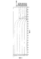
図5は、実施の形態1にかかる太陽電池ストリングを構成する太陽電池モジュールの基準温度25℃における出力I−V(電流−電圧)特性の温度依存性を説明する図である。図6は、実施の形態1にかかる太陽電池ストリングを構成する太陽電池モジュールの基準温度25℃における出力P−V(電力−電圧)特性の温度依存性を説明する図である。図5および図6は、それぞれ太陽電池モジュールの測定の基準条件であるモジュール温度25℃における日射量が日射強度1000W/m2、800W/m2、600W/m2、400W/m2および200W/m2であるときの特性を示している。 FIG. 5 is a diagram illustrating the temperature dependence of the output IV (current-voltage) characteristic at a reference temperature of 25 ° C. of the solar cell module constituting the solar cell string according to the first embodiment. FIG. 6 is a diagram illustrating the temperature dependence of the output PV (power-voltage) characteristic at a reference temperature of 25 ° C. of the solar cell module constituting the solar cell string according to the first embodiment. In FIGS. 5 and 6, the amount of solar radiation at a module temperature of 25 ° C., which is a reference condition for measuring the solar cell module, is 1000 W / m 2 , 800 W / m 2 , 600 W / m 2 , 400 W / m 2 and 200 W /, respectively. The characteristics when it is m 2 are shown.
図6から、日射量に応じて最大出力電力値Pmmpptが変化し、最大出力電力値Pmmpptに対応した最大出力動作電圧値Vpmmpptは一定電圧値ではなく、最大出力電力値Pmmpptに対して変化量関係式にて表現できることがわかる。ここでは、簡単のため最大出力電力値Pmmpptの変化量と最大出力動作電圧値Vpmmpptの変化量との関係が1次式で近似できるとして説明するが、評価精度を高めるためには多項式で近似するのが望ましい。1次式で近似したときの、最大出力電力値Pmmpptの変化量に対する最大出力動作電圧値Vpmmpptの変化量の比を最大出力動作電圧変化量ΔVpm(V/W)とする。 6, the maximum output power value Pm mppt changes according to the amount of solar radiation, the maximum output power value Pm mppt maximum output operating voltage value corresponding to Vpm mppt is not constant voltage value, to the maximum output power value Pm mppt It can be seen that it can be expressed by the change amount relational expression. Here, for the sake of simplicity, the relationship between the amount of change in the maximum output power value Pm mppt and the amount of change in the maximum output operating voltage value Vpm mppt can be approximated by a linear equation, but in order to improve the evaluation accuracy, a polynomial is used. It is desirable to approximate. The ratio of the change amount of the maximum output operating voltage value Vpm mppt to the change amount of the maximum output power value Pm mppt when approximated by the linear equation is defined as the maximum output operating voltage change amount ΔVpm (V / W).
図7は、実施の形態1にかかる最大出力動作電圧変化量ΔVpm(V/W)を求めるためのデータを示す図である。図7は、図6における最大出力点Aおよび最大出力点Bのデータを纏めた表になっている。最大出力点Aは、日射強度1000W/m2において最大出力になったときの最大出力電力値Pmおよび最大出力動作電圧値Vpmを示す点であり、最大出力点Bは、日射強度200W/m2において最大出力になったときの最大出力電力値Pmおよび最大出力動作電圧値Vpmを示す点である。この二つの最大出力点より、モジュール温度が25℃であるときにおける最大出力動作電圧変化量ΔVpm=0.0069(V/W)が求められる。 FIG. 7 is a diagram showing data for obtaining the maximum output operating voltage change amount ΔVpm (V / W) according to the first embodiment. FIG. 7 is a table summarizing the data of the maximum output point A and the maximum output point B in FIG. The maximum output point A is a point indicating the maximum output power value Pm and the maximum output operating voltage value Vpm when the maximum output is reached at a solar radiation intensity of 1000 W / m 2 , and the maximum output point B is a solar radiation intensity of 200 W / m 2. It is a point showing the maximum output power value Pm and the maximum output operating voltage value Vpm when the maximum output is reached. From these two maximum output points, the maximum output operating voltage change amount ΔVpm = 0.0069 (V / W) when the module temperature is 25 ° C. can be obtained.
すなわち、太陽電池モジュールが温度25℃の下では、任意の日射強度の下での最大出力電力値Pmと最大出力動作電圧値Vpmとの関係は一義的であり、両数値のモジュール温度に対する温度係数を予め測定しておくことにより、当該温度係数が適用できる範囲では、任意のモジュール温度における任意の日射強度下において太陽電池モジュールが最大動作電力点で発電しているならば、その発生電圧を計算できる事が理解できる。 That is, when the temperature of the solar cell module is 25 ° C., the relationship between the maximum output power value Pm and the maximum output operating voltage value Vpm under an arbitrary solar intensity is unique, and the temperature coefficients of both values with respect to the module temperature are unique. By measuring in advance, if the solar cell module is generating power at the maximum operating power point under any solar radiation intensity at any module temperature within the range to which the temperature coefficient can be applied, the generated voltage is calculated. I understand what I can do.
さらに、モジュール温度が25℃以外の温度の下での最大出力動作電圧値Vpmと最大出力電力値Pmとの変化量関係式はモジュール温度が25℃のときの変化量関係式とは異なる。しかし、太陽電池モジュールを屋外に設置して異なる周囲温度下にてモジュール温度を25℃から変化させ、各モジュール温度のそれぞれの場合について変動する日射量下、すなわち日射強度下においてI−Vカーブ測定器を用いて最大出力電力点での最大出力動作電圧値Vpmmpptおよび最大出力電力値Pmmpptを測定することで、モジュール温度別の最大出力動作電圧変化量ΔVpmを実測して、診断精度を向上させる事も容易に可能である。 Further, the change amount relational expression between the maximum output operating voltage value Vpm and the maximum output power value Pm when the module temperature is other than 25 ° C. is different from the change amount relational expression when the module temperature is 25 ° C. However, the solar cell module is installed outdoors and the module temperature is changed from 25 ° C. under different ambient temperatures, and the IV curve is measured under the amount of solar radiation that fluctuates in each case of each module temperature, that is, under the solar radiation intensity. By measuring the maximum output operating voltage value Vpm mppt and the maximum output power value Pm mppt at the maximum output power point using a device, the maximum output operating voltage change amount ΔVpm for each module temperature is actually measured to improve diagnostic accuracy. It is also possible to make it easily.
太陽電池モジュールの温度が不明の状態で、日射強度1000W/m2において最大出力電力値Pmmpptおよび最大出力動作電圧値Vpmmpptが測定された場合、以上説明した原理も利用して、温度推定部11は、基準条件のモジュール温度25℃に対する実際のモジュール温度の差を計算する。具体的には、温度推定部11は、測定された最大出力動作電圧値Vpmmpptと公称最大出力動作電圧値Vpm0との差分を最大出力動作電圧温度係数αVpm(%/℃)によって除算する事で、基準条件のモジュール温度25℃と実際のモジュール温度の推定値との温度差を計算する。温度推定部11は、この温度差を計算することにより、実際のモジュール温度を推定していることになる。
When the maximum output power value Pm mppt and the maximum output operating voltage value Vpm mppt are measured at a solar intensity of 1000 W / m 2 when the temperature of the solar cell module is unknown, the temperature estimation unit also uses the principle described above.
そして、出力診断部12は、温度推定部11が求めたモジュール温度の温度差と、最大出力温度係数αPmax(%/℃)とを用いて、測定した最大出力電力値Pmmpptを基準条件であるモジュール温度25℃における日射強度1000W/m2での最大出力電力値Pmmppt(at25℃)に換算する。この値と太陽電池モジュールの公称最大出力電力値Pm0とを比較する事で、太陽電池診断装置1は、太陽電池モジュールの温度を実際に測定することを要さずに、公称最大出力電力値Pm0に対する太陽電池モジュールの出力性能の診断を実行することが可能となる。
Then, the
なお、日射強度が1000W/m2と異なる場合は、最大出力電力値Pmmpptの測定値も図6に示すように日射強度に対し比例して変化する。そして、日射強度が1000W/m2の場合の最大出力点Aと、日射強度が200W/m2の場合の最大出力点Bとを比べればわかるように、最大出力動作電圧値Vpmmpptも最大出力動作電圧変化量ΔVpm(V/W)に比例して変化する。 When the solar radiation intensity is different from 1000 W / m 2 , the measured value of the maximum output power value Pmmppt also changes in proportion to the solar radiation intensity as shown in FIG. Then, as can be seen by comparing the maximum output point A when the solar radiation intensity is 1000 W / m 2 and the maximum output point B when the solar radiation intensity is 200 W / m 2 , the maximum output operating voltage value Vpm mppt is also the maximum output. It changes in proportion to the amount of change in operating voltage ΔVpm (V / W).
日射強度と最大出力電力値Pmmpptとの関係は、太陽電池モジュールの分光感度特性が影響を受ける夕方といった時間帯を除けば、一般には1次式の関係を有している。したがって、日射強度が200W/m2での最大出力電力値Pmmpptの測定値を、基準条件である日射強度1000W/m2における最大出力電力値Pmmppt(at1000W/m2)に換算するには、5倍(=1000/200)すれば良い。また、最大出力動作電圧値Vpmmpptの測定値についても、日射強度1000W/m2下での値として換算が必要である。診断対象となる太陽電池モジュールの日射強度1000W/m2における最大出力電力値Pmmppt(at1000W/m2)と測定された日射強度での最大出力電力値Pmmpptの測定値との差分に最大出力動作電圧変化量ΔVpm=0.0069(V/W)を乗算して、測定された日射強度での最大出力動作電圧値Vpmmpptの測定値に加算することで、日射強度1000W/m2下での最大出力動作電圧値Vpmmppt(at1000W/m2)に換算することができる。 The relationship between the solar radiation intensity and the maximum output power value Pmmppt generally has a linear relationship except in the evening when the spectral sensitivity characteristics of the solar cell module are affected. Therefore, to convert the measured value of the maximum output power value Pm mppt in irradiance is 200 W / m 2, the maximum output power value Pm mppt (at1000W / m 2) in the solar irradiance 1000W / m 2, which is the reference condition It may be multiplied by 5 (= 1000/200). In addition, the measured value of the maximum output operating voltage value Vpm mpt also needs to be converted as a value under a solar radiation intensity of 1000 W / m 2 . Maximum output to the difference between the maximum output power value Pm mppt (at1000W / m 2) and the maximum output power value Pm measurement of mppt in the measured solar irradiance at the irradiance 1000W / m 2 of the solar cell module to be diagnosed By multiplying the operating voltage change amount ΔVpm = 0.0069 (V / W) and adding it to the measured value of the maximum output operating voltage value Vpm mpt at the measured solar intensity, the solar intensity is 1000 W / m 2 . It can be converted to the maximum output operating voltage value of Vpm mpt (at 1000W / m 2 ).
以上のように、与えられた日射強度下において測定された最大出力電力値Pmmpptおよび最大出力動作電圧値Vpmmpptを日射強度1000W/m2における最大出力電力値Pmmppt(at1000W/m2)および最大出力動作電圧値Vpmmppt(at1000W/m2)に換算することができる。温度推定部11は、これらの数値を用いることにより、上述したように太陽電池モジュールの温度の推定を実行する。さらに、このようにして求めた太陽電池モジュールの温度推定値が、上で用いた最大出力動作電圧変化量ΔVpmが求められた温度からの差異が大きい値となる場合がある。上では、例として基準条件の温度である25℃における最大出力動作電圧変化量ΔVpm=0.0069(V/W)を用いたので、温度推定部11が求めた推定温度の25℃からの差異が大きい値になった場合がこれにあたる。このような場合は、温度推定部11が求めた推定温度で適用できるように予め求めておいた最大出力動作電圧変化量ΔVpmを用いて、上述のようにして再び太陽電池モジュールの温度を温度推定部11が推定することにより、推定温度の誤差を低減することが可能である。したがって、この作業による温度推定を繰り返し実行して温度推定値を収束値に漸近させることも可能である。
As described above, the maximum output power value measured maximum output power value Pm mppt and maximum output operating voltage Vpm mppt under a given solar irradiance at the irradiance 1000W / m 2 Pm mppt (at1000W / m 2) and It can be converted to the maximum output operating voltage value Vpm mpt (at 1000W / m 2 ). The
なお、太陽電池モジュールの公称値を得るための出力性能測定ではソーラーシミュレータによって日射強度に対する出力性能測定を実行するが、この測定方法は日没時等での太陽光スペクトルの変化に対する太陽電池モジュールの分光感度を考慮していない。したがって、太陽電池の性能を、屋外環境等で測定した上で、設置地域の緯度および経度情報、季節および時刻に依存した太陽位置を考慮して、測定条件として一定以上の日射量または太陽位置条件によって制限を加えることが行われていた。しかし、設置された太陽電池モジュールと同一分光感度のセルを用いた日射センサを光電式の日射計7に用いて日射量測定を実施することにより上記制限の条件を緩和することが可能である。すなわち、太陽の位置によるスペクトル変動または太陽電池モジュールのスペクトル感度による誤差を縮小する為に、設置された太陽電池モジュールと同一分光感度のセルを用いた日射センサを日射計7に用いる事で日射量の測定値の測定環境による誤差の縮小も可能である。そして、日射に対する応答速度が例えば1msec以下のように、太陽電池モジュールと同等レベルの高応答速度を有する日射計7を使用することで、雲の動きといった日射変動条件下の性能診断精度の向上が可能になる。 In the output performance measurement to obtain the nominal value of the solar cell module, the output performance measurement for the solar radiation intensity is performed by the solar simulator. This measurement method is used for the solar cell module in response to changes in the solar spectrum at sunset or the like. Spectral sensitivity is not considered. Therefore, after measuring the performance of the solar cell in an outdoor environment, etc., the amount of solar radiation or the sun position condition above a certain level is taken into consideration as the measurement condition in consideration of the latitude and longitude information of the installation area and the sun position depending on the season and time. Was being restricted by. However, the above limitation can be relaxed by measuring the amount of solar radiation by using a solar radiation sensor using a cell having the same spectral sensitivity as the installed solar cell module in the photoelectric type pyranometer 7. That is, in order to reduce the spectral fluctuation due to the position of the sun or the error due to the spectral sensitivity of the solar cell module, the amount of solar radiation is increased by using a solar radiation sensor using a cell having the same spectral sensitivity as the installed solar cell module for the pyranometer 7. It is also possible to reduce the error depending on the measurement environment of the measured value of. Then, by using a pyranometer 7 having a high response speed equivalent to that of the solar cell module, such as a response speed to solar radiation of 1 msec or less, the accuracy of performance diagnosis under solar radiation fluctuation conditions such as cloud movement can be improved. It will be possible.
実施の形態1にかかる太陽電池診断装置1による太陽電池診断方法に対する理解を助けるために、図1より簡単な構成の太陽光発電システムを用いて、以下では具体的に説明する。図8は、実施の形態1にかかる太陽光発電システム101の構成を示す図である。太陽光発電システム101は、図1の太陽光発電システム100を簡素化した構成であり、太陽電池ストリング3および接続箱6が省かれている。さらに、太陽光発電システム101の太陽電池ストリング2は4つの太陽電池モジュール111が直列接続したString1のみからなる。図8の太陽電池診断装置1は、パワーコンディショナ4のMPPT制御部4aより、信号変換器9を介してMPPT制御データを取得する。また、太陽電池診断装置1は、太陽電池ストリング2への日射強度を、太陽電池ストリング2への日射強度と日射強度が同一であるとみなせる箇所に設置された日射計7より信号変換器8を介して上記MPPT制御データと時間同期して取得する。
In order to help the understanding of the solar cell diagnostic method by the solar cell
太陽電池診断装置1は、診断対象となる太陽電池ストリング2を構成する太陽電池モジュール111の公称最大出力値Pmmodより、太陽電池ストリング2の構成に応じた、基準条件(日射強度1000W/m2,温度25℃)における太陽電池ストリング2の公称最大出力電力値StrPmaxを性能診断における判断基準となる公称定格値として算出しておく。太陽電池診断装置1は、取得した上記MPPT制御データ、上記日射強度および診断対象となる太陽電池ストリング2の構成情報に基づいて、太陽電池ストリング2の温度測定を実施することなく、太陽電池ストリング2の基準条件(日射強度1000W/m2,温度25℃)における最大出力電力値を算出し、太陽電池ストリング2の公称最大出力電力値StrPmaxと比較することで太陽光発電システム101の性能診断を以下の方法で実施する。
The solar cell
また、太陽電池ストリング2とパワーコンディショナ4との間を接続するケーブル線50による導体抵抗損失を補正するために、ケーブル線仕様およびケーブル長を考慮に入れること、総延長距離の明確化、接続箱5の使用の有無による損失計算も性能診断の高精度化には有効である。
Also, in order to correct the conductor resistance loss due to the
診断対象となる図8の太陽電池ストリング2の構成および公称定格値を以下に纏めて示す。
(1)ストリング構成
太陽電池モジュール111の型名:Pvmodule
接続構成:Pvmoduleの4直列接続
太陽電池ストリング2とパワーコンディショナ4との間のケーブル線仕様
:H-CV線 3.5mm2線、延長距離25m(往復50m)
(2)基準条件(日射強度1000W/m2,温度25℃)における太陽電池モジュール(型名:Pvmodule)公称定格値および温度係数
公称最大出力値Pmmod:245(W)
公称最大出力動作電圧値Vpmmod:26.6(V)
公称最大出力動作電流値Ipmmod:9.22(A)
公称開放電圧Voc:32.7(V)
公称短絡電流Isc:9.79(A)
最大出力温度係数αPmax:−0.42(%/℃)
最大出力動作電圧温度係数αVpm:−0.40(%/℃)
最大出力動作電圧変化量ΔVpm:0.0069(V/W)
(3)上記(1)および(2)のデータより計算される診断対象となる太陽電池ストリング2の基準条件における公称定格値および温度係数
公称最大出力電力値StrPmax:245(W)×4枚=980(W)
公称最大出力動作電圧値StrVpm:26.6(V)×4枚=106.4(V)
最大出力温度係数αPmax:−0.42(%/℃)
最大出力動作電圧温度係数αVpm:−0.40(%/℃)
最大出力動作電圧変化量ΔVpm:0.0069(V/W)
The configuration and nominal rated value of the
(1) String configuration Model name of solar cell module 111: Pvmodule
Connection configuration: 4-series connection of Pvmodule Cable line between
(2) Solar cell module (model name: Pvmodule) nominal rated value and temperature coefficient nominal maximum output value Pm mod : 245 (W) under standard conditions (solar intensity 1000 W / m 2 , temperature 25 ° C)
Nominal maximum output operating voltage value Vpm mod : 26.6 (V)
Nominal maximum output operating current value Ipm mod : 9.22 (A)
Nominal open circuit voltage Voc: 32.7 (V)
Nominal short circuit current Isc: 9.79 (A)
Maximum output temperature coefficient αPmax: -0.42 (% / ° C)
Maximum output operating voltage Temperature coefficient αVpm: -0.40 (% / ° C)
Maximum output operating voltage change amount ΔVpm: 0.0069 (V / W)
(3) Nominal rated value and temperature coefficient nominal maximum output power value under the reference conditions of the
Nominal maximum output operating voltage value StrVpm: 26.6 (V) x 4 sheets = 106.4 (V)
Maximum output temperature coefficient αPmax: -0.42 (% / ° C)
Maximum output operating voltage Temperature coefficient αVpm: -0.40 (% / ° C)
Maximum output operating voltage change amount ΔVpm: 0.0069 (V / W)
図8の太陽電池ストリング2の構成は太陽電池モジュール111の4直列1並列構成である事から、太陽電池ストリング2の公称最大出力電力値StrPmaxは、単純に計算が可能である。なお、最大出力動作電圧変化量ΔVpmは、太陽電池モジュール111が並列構成ならば値が変化する。具体的には、4直列1並列構成が4直列2並列構成になると、出力電力が2倍化することから、最大出力動作電圧変化量ΔVpmは、上記した値の1/2の0.00345(V/W)となる。
Since the configuration of the
次に、実際の測定結果に基づいて、実施の形態1にかかる太陽光発電システム101が実行する太陽電池診断方法における計算手法を、太陽電池ストリング2を設置した直後の初期性能測定結果値を用いて説明する。
Next, based on the actual measurement result, the calculation method in the solar cell diagnostic method executed by the photovoltaic
まず、日射計7が日射強度を測定すると共に、パワーコンディショナ4がMPPT制御を実行している状態での太陽電池ストリング2の最大出力動作電圧値Vpmmpptおよび最大出力動作電流値Ipmmpptを日射強度の測定と時間的に同期したタイミングにおいて測定する。以下が測定結果である。
日射強度:700W/m2
MPPT制御下での最大出力動作電圧値Vpmmppt:84.9(V)
MPPT制御下での最大出力動作電流値Ipmmppt:6.55(A)
First, the solar radiation meter 7 measures the solar radiation intensity, and the maximum output operating voltage value Vpm mppt and the maximum output operating current value Ipm mppt of the
Solar intensity: 700 W / m 2
Maximum output operating voltage value under MPPT control Vpm mppt : 84.9 (V)
Maximum output operating current value under MPPT control Ipm mppt : 6.55 (A)
また、太陽電池ストリング2の温度推定の誤差を減らすために、ケーブル線50での電力損失による電圧降下を考慮する。したがって、ケーブル線50のケーブル種類に基づいた抵抗値5.2(Ω/km)と、前述した(1)ストリング構成におけるケーブル線仕様とから、以下のようにケーブル線50の抵抗値であるケーブル抵抗Rcを求める。
Further, in order to reduce the error of the temperature estimation of the
Rc=5.2(Ω/km)×(50m/1000m)(km)=0.26(Ω) Rc = 5.2 (Ω / km) x (50m / 1000m) (km) = 0.26 (Ω)
以上のVpmmppt、IpmmpptおよびRcから、上記電圧降下による電圧降下の値をVpmmpptに加算して補正することにより太陽電池ストリング2の最大出力動作電圧値Vpmmeasureが以下のように求まる。
More Vpm mppt, from Ipm mppt and Rc, maximum output operating voltage Vpm its measure of the
Vpmmeasure=Vpmmppt+Rc*Ipmmppt=84.9+0.26*6.55=86.603(V) Vpm tape measure = Vpm mppt + Rc * Ipm mppt = 84.9 + 0.26 * 6.55 = 86.603 (V)
そして、上で求めたVpmmeasureに基づいて、太陽電池ストリング2の最大出力電力値StrPmaxmeasureが以下のように求まる。
Based on Vpm its measure determined above, the maximum output power value StrPmax its measure of the
StrPmaxmeasure=Vpmmeasure*Ipmmppt=Vpmmppt*Ipmmppt+Rc*Ipmmppt*Ipmmppt=567.25(W) StrPmax measure = Vpm measure * Ipm mppt = Vpm mppt * Ipm mppt + Rc * Ipm mppt * Ipm mppt = 567.25 (W)
さらに、上で求めた日射強度が700W/m2時の太陽電池ストリング2の最大出力電力値StrPmaxmeasureを、以下のように日射強度が1000W/m2時の太陽電池ストリング2の最大出力電力値StrPmaxcalc1000に換算する。
Furthermore, the maximum output power value StrPmax its measure of the
StrPmaxcalc1000=StrPmaxmeasure×(1000/測定された日射強度)=567.25(W)×1000/700=810.36(W) StrPmax calc1000 = StrPmax measure × (1000 / measured solar irradiance) = 567.25 (W) × 1000 /700 = 810.36 (W)
上で求めたStrPmaxcalc1000から、上記(3)で示した公称最大出力電力値StrPmaxおよび最大出力動作電圧変化量ΔVpmを用いて、以下のように日射強度が1000W/m2時の太陽電池ストリング2の最大出力動作電圧値Vpmcalc1000を求めることができる。
From the StrPmax calc1000 obtained above, using the nominal maximum output power value StrPmax and the maximum output operating voltage change amount ΔVpm shown in (3) above, the
Vpmcalc1000=Vpmmeasure+ΔVpm×(StrPmax−StrPmaxcalc1000)=86.603(V)+0.0069(V/W)×(980(W)−810.36(W))=87.774(V) Vpm calc1000 = Vpm measure + ΔVpm × (StrPmax-StrPmax calc1000 ) = 86.603 (V) +0.0069 (V / W) × (980 (W) 810.36 (W)) = 87.774 (V)
なお、ケーブル線50による電圧降下が無視できる場合は、Vpmmeasureの代りに、Vpmmpptを用いて上記計算を実行してもよい。上で求めたVpmcalc1000から、上記(3)で示した太陽電池ストリング2の公称最大出力動作電圧値StrVpmおよび最大出力動作電圧温度係数αVpmを用いて、温度推定部11は太陽電池ストリング2の温度推定値StrTm(℃)を求める。具体的には、Vpmcalc1000の公称最大出力動作電圧値StrVpmからの変化比を求めて、最大出力動作電圧温度係数αVpmを用いて、以下のように温度推定値StrTm(℃)を求める。
If the voltage drop due to the
StrTm(℃)=((Vpmcalc1000―StrVpm)/StrVpm)/αVpm+基準条件の温度
=((87.774(V)−106.4(V))/106.4(V))/(−0.004(/℃))+25℃
=68.8℃
StrTm (° C.) = ((Vpm calc1000- StrVpm) / StrVpm) / αVpm + reference condition temperature = ((87.774 (V) -106.4 (V)) / 106.4 (V)) / (-0 .004 (/ ° C)) + 25 ° C
= 68.8 ° C
なお、上記の結果では、太陽電池ストリング2の温度推定値StrTm(℃)と、Vpmcalc1000を求めるときに用いた最大出力動作電圧変化量ΔVpmを求めた基準条件の温度25℃との温度差が大きい。したがって、最大出力動作電圧変化量ΔVpmの値を上で求めた温度推定値StrTmである68.8℃時の最大出力動作電圧変化量の値にしてVpmcalc1000の値を再計算して、温度推定値StrTmを再び求めて、温度推定値StrTmと、最大出力動作電圧変化量ΔVpmの適用温度との差が小さくなるようにして、推定精度を高めても良い。
In the above result, the temperature difference between the estimated temperature value StrTm (° C.) of the
また、上記では、電力差である(StrPmax−StrPmaxcalc1000)=(980(W)−810.36(W))から最大出力動作電圧値Vpmcalc1000を求めて、太陽電池ストリング2の出力電圧値の温度係数である最大出力動作電圧温度係数αVpmを用いて温度推定値StrTmを求めた。しかし、StrPmaxおよびStrPmaxcalc1000から太陽電池ストリング2の出力電力値の温度係数である最大出力温度係数αPmaxを用いて温度推定値StrTmを求めることもできる。
Further, in the above, the maximum output operating voltage value Vpm calc1000 is obtained from the power difference (StrPmax-StrPmax calc1000 ) = (980 (W) -810.36 (W)), and the output voltage value of the
上記したように、温度推定部11は、太陽電池ストリング2の温度推定値StrTm(℃)の基準条件の温度25℃との温度差を求めることにより、温度推定値StrTm(℃)を求める。したがって、温度推定部11は、測定された日射強度、最大出力動作電圧値Vpmmpptおよび最大出力動作電流値Ipmmpptに基づいて、温度推定値StrTm(℃)を求めるまでの上記計算を自らが全て実行してもよい。
As described above, the
温度推定部11が求めたStrTmと、上記(3)で示した最大出力温度係数αPmaxとを用いて、出力診断部12は、上で求めたStrPmaxcalc1000を、以下のように診断対象の太陽電池ストリング2が25℃時における出力、すなわち基準条件(日射強度1000W/m2,温度25℃)における太陽電池ストリング2の最大出力電力値に換算する。
StrPmaxcalc1000/(1+(αPmax)*(StrTm−25))
=810.36(W)/(1−0.0042(/℃)×(68.8℃−25℃))
=993.0(W)
Using the StrTm obtained by the
StrPmax calc1000 / (1+ (αPmax) * (StrTm-25))
= 810.36 (W) / (1-0.0042 (/ ° C) x (68.8 ° C-25 ° C))
= 993.0 (W)
太陽電池診断装置1は、出力診断部12が求めた基準条件における太陽電池ストリング2の最大出力電力値993.0(W)の上記(3)で示した公称最大出力電力値StrPmax=980(W)との出力性能比を求めることができる。
993.0(W)/980(W)=101.3%
The solar cell
993.0 (W) /980 (W) = 101.3%
太陽電池診断装置1は、上で求めた出力性能比に基づいて、太陽電池ストリング2の出力劣化の診断が可能となる。上記の例は、基準条件における太陽電池ストリング2の最大出力電力値が公称定格値よりやや上昇していることを示している。
The solar cell
以上説明したように、実施の形態1にかかる太陽電池診断装置1によれば、測定された日射強度、パワーコンディショナ4がMPPT制御下での最大出力動作電圧値Vpmmpptおよび最大出力動作電流値Ipmmpptの3つの測定データに基づいて、太陽電池ストリング2の性能診断が可能である。このように実施の形態1にかかる太陽電池診断方法は、太陽電池ストリング2の温度測定を必要とせずに太陽電池ストリング2の温度を推定して性能を診断する簡便な手法である。したがって、太陽光発電システム100の測定機器を簡素化することができ、保守も容易になる。
As described above, according to the solar cell
実施の形態1にかかる太陽電池診断方法は、一回の診断で必要となる測定データのデータ量が少ないので、長時間にわたって測定した場合のデータ量も少なくなる。したがって、さまざまな日射条件下での測定データに基づいた統計的処理による診断の高精度化が可能となる。具体的には、長時間観測をおこなうことで、日射量または出力性能比の記録に対し、変動が少ない領域を抽出するといった統計的処理を実施して、出力性能比の高精度化を図ることが容易に可能となる。さらに、太陽電池診断装置1にこれら統計処理の記録機能および診断結果の表示機能を設けることが可能である。
In the solar cell diagnosis method according to the first embodiment, since the amount of measurement data required for one diagnosis is small, the amount of data when measured over a long period of time is also small. Therefore, it is possible to improve the accuracy of diagnosis by statistical processing based on measurement data under various solar radiation conditions. Specifically, by observing for a long time, statistical processing such as extracting a region with little fluctuation from the recording of the amount of solar radiation or the output performance ratio is performed to improve the accuracy of the output performance ratio. Is easily possible. Further, the solar cell
また、太陽電池診断装置1が精度の高い診断をするためには、日射計7により測定された日射量の値が高く且つ測定した日射量の変動が小さい時間帯が好適である。したがって、温度推定部11が太陽電池ストリング2の温度推定値StrTmを推定するよりも前に測定された日射強度に基づいて、太陽電池診断装置1は、温度推定値StrTmを求めるために用いる日射強度、最大出力動作電圧値Vpmmpptおよび最大出力動作電流値Ipmmpptを測定するのに適した時間帯を設定する。そして、太陽電池診断装置1は、当該時間帯に測定された測定結果に基づいて温度推定値StrTmを推定して出力診断を実行することができる。また、日射強度が安定した条件等の測定条件設定を追加したり、測定結果に対して同様な条件での統計処理を加えた出力診断も容易である。
Further, in order for the solar cell
なお、太陽光発電システム100のシステム設計では、年間発電量を予測計算するために、太陽光発電システム100の緯度および経度からなる設置位置情報、各太陽電池ストリングの設置方位角および設置傾斜角といった設置情報を使用する。したがって、これらの設置情報に対応する太陽電池ストリング2,3が接続されるパワーコンディショナ4のMPPT制御部4a,4bの入力チャンネル番号を当該設置情報と関連づけて太陽電池診断装置1に登録し、さらには日射計7の設置方位角および設置傾斜角も利用することにより、太陽電池ストリング毎の性能診断も可能となる。具体的には、太陽電池診断装置1は、各太陽電池ストリングの設置方位角および設置傾斜角といった設置情報と、日射計7の設置方位角および設置傾斜角といった設置情報と、に基づいて、各太陽電池ストリングにおける日射強度を近似するように日射計7の測定値から得た日射強度の値を補正する。すなわち、太陽電池診断装置1によれば、複数の太陽電池ストリング2,3が異なる方位面に設置されていても、一つの日射計7の測定データに基づいて各太陽電池ストリング2,3の受光面における日射強度への換算が可能である。したがって、実施の形態1にかかる太陽電池診断方法は、寄棟住宅などのように多面にわたって太陽電池ストリング2,3を設置している太陽光発電システム100の性能診断に適用することも容易である。なお、複数の日射計7を太陽電池ストリング2,3の傍にそれぞれ備えるようにして、診断性能の高精度化を図ってもかまわない。
In the system design of the photovoltaic
また、太陽電池診断装置1は様々な種類の太陽光発電システム100に用いられるので、使用されるパワーコンディショナ4は、機種に依存したMPPT制御の固有の時間応答性を有し、日射量が少ない領域などにおいてトラッキング誤差が発生する機種も存在する。これらの情報はMPPT制御性能値として、パワーコンディショナ機種情報と共に太陽電池診断装置1に登録しておき、取得した日射強度および日射強度変動値に対し、MPPT制御性能値に基づいたデータフィルタリングを実行し、変動している日射量の下でも出力性能比を求めることができる機能を太陽電池診断装置1に搭載することも可能である。
Further, since the solar cell
以上のように、実施の形態1にかかる太陽電池診断装置1が実施する、パワーコンディショナ4のMPPT制御データおよび日射量測定データを用いた太陽電池診断方法は、性能診断に要するハードウェア量およびデータ量を従来技術に比べて低減することができる。すなわち、実施の形態1にかかる太陽電池診断方法は、組込みおよび運用が容易で低コストな手法であり、多数の太陽光発電システムからなる太陽光発電運用システムの中央診断装置に適用することも可能である。
As described above, the solar cell diagnostic method using the MPPT control data and the solar radiation amount measurement data of the power conditioner 4 carried out by the solar cell
実施の形態1にかかる太陽電池診断方法を実現するために従来の太陽光発電システムへの追加が必要となる計測器は日射量の測定計器のみであり、利用する情報はパワーコンディショナ4がモニタしているMPPT制御データであることから診断のための追加的なコストが低く、また必要となる測定データのデータ量も少ない。すなわち、実施の形態1にかかる太陽電池診断方法は、系統連系動作中のパワーコンディショナ4の制御機能および制御時のデータを利用することで安価に実現可能な方法である。 In order to realize the solar cell diagnostic method according to the first embodiment, the only measuring instrument that needs to be added to the conventional photovoltaic power generation system is the solar radiation measuring instrument, and the information to be used is monitored by the power conditioner 4. Since the MPPT control data is used, the additional cost for diagnosis is low, and the amount of measurement data required is also small. That is, the solar cell diagnostic method according to the first embodiment is a method that can be inexpensively realized by using the control function of the power conditioner 4 during the grid interconnection operation and the data at the time of control.
また、実施の形態1にかかる太陽電池診断方法によれば、変動する日射量の下でのリアルタイム診断が可能である。したがって、太陽電池モジュールのガラス面清掃の前後の基準条件における太陽電池ストリングの最大出力電力値を求めることにより、ガラス面清掃による出力改善効果が短時間で検証することができる。これを利用して、複数の太陽電池モジュールの一部についてガラス面清掃前後の出力改善効果を実施の形態1にかかる太陽電池診断方法を用いて比較することにより、作業の費用対効果によるメンテナンス実施判断に応用することも可能になる。すなわち、太陽電池モジュールのガラス面清掃前後による性能診断からガラス面清掃による出力改善効果が定量的にわかるので、この結果に基づいて、保守計画を立案することが可能となる。 Further, according to the solar cell diagnosis method according to the first embodiment, real-time diagnosis under a fluctuating amount of solar radiation is possible. Therefore, by obtaining the maximum output power value of the solar cell string under the reference conditions before and after cleaning the glass surface of the solar cell module, the output improvement effect by cleaning the glass surface can be verified in a short time. Utilizing this, the output improvement effect before and after cleaning the glass surface of a part of a plurality of solar cell modules is compared by using the solar cell diagnostic method according to the first embodiment, and maintenance is carried out cost-effectively. It can also be applied to judgment. That is, since the output improvement effect by cleaning the glass surface can be quantitatively understood from the performance diagnosis before and after cleaning the glass surface of the solar cell module, it is possible to formulate a maintenance plan based on this result.
以上説明したように、実施の形態1にかかる太陽電池診断方法によれば、太陽電池ストリングの温度測定を実施せずに少ない測定データに基づいて、高い精度で出力性能判断が可能な太陽電池診断装置1を安価に得る事ができる。また、実施の形態1にかかる太陽電池診断装置1によれば、リモート監視および効率的なデータ記録が可能となることから、長期間にわたる保守データ管理が容易である。
As described above, according to the solar cell diagnosis method according to the first embodiment, the solar cell diagnosis capable of determining the output performance with high accuracy based on a small amount of measurement data without performing the temperature measurement of the solar cell string. The
実施の形態2.
図9は、本発明の実施の形態2にかかる太陽光発電システム200の構成を示す図である。図1に示した実施の形態1にかかる太陽光発電システム100との違いは、信号変換器8が省かれて、日射計7が信号変換器9に接続されていることである。図9の太陽電池診断装置1は中央診断装置であり、図9の太陽光発電システム200は、太陽電池診断装置1によりリモート監視される。太陽電池診断装置1は有線または無線の通信機能を有し、インターネットなどを介して信号変換器9と接続する。実施の形態2にかかる太陽電池診断装置1が実施する太陽電池診断方法は実施の形態1と同じである。したがって、1つの太陽電池診断装置1に対して、診断対象となる複数の太陽光発電システム200が存在してもかまわない。
FIG. 9 is a diagram showing a configuration of a photovoltaic
図9に示すように、太陽光発電システム200において、信号変換器9に日射量を含む測定データの通信機能を備えさせることにより、太陽電池診断装置1を太陽光発電システム200の設置現場に設けなくて済む。これにより、太陽光発電システム200の設置現場と通信で接続された中央診断装置である太陽電池診断装置1において、大規模かつ複数の太陽光発電システム200の集中リモート監視による性能診断を実施する事が可能となる。実施の形態1でも述べたように、実施の形態2にかかる太陽電池診断装置1が実施する太陽電池診断方法は、一回の診断で必要となる測定データのデータ量が少ないので、リモート監視における通信量も少なくて済むので、太陽光発電システム200の設置システム情報を太陽電池診断装置1において一括管理し、診断時においては、太陽光発電システム200からの測定データを用いることができる。すなわち、太陽電池診断装置1は、太陽光発電システム200を常時監視し、さらに、経年的な監視および診断に必要な診断データを管理するのに好適である。
As shown in FIG. 9, in the photovoltaic
実施の形態2にかかる太陽電池診断装置1においては、太陽電池ストリング2,3それぞれの公称最大出力電力値と出力診断部12が求めた基準条件における太陽電池ストリング2,3の最大出力電力値とを比較する。太陽電池診断装置1は、出力診断部12が求めた基準条件における太陽電池ストリング2,3の最大出力電力値を公称最大出力電力値に対する百分率表示にて出力性能の診断結果として太陽電池診断装置1の表示装置に時系列で表示させて経年劣化診断を行うことができる。また、太陽電池診断装置1は、気象情報を利用して降雨前後の太陽電池ストリング2,3の出力性能の変化を求めたり、太陽電池モジュールのガラス面の洗浄前後の出力性能差の結果に基づいて太陽電池ストリング2,3の洗浄メンテナンスの要否判断をするといった各種機能を備えることが可能である。さらに、太陽電池診断装置1は、好適な測定時間帯を設定する測定設定機能および測定結果のダウンロード機能など容易に組込み可能な構成をとる。
In the solar cell
なお、太陽電池診断装置1として汎用コンピュータを採用し、パワーコンディショナ4および日射計7と信号変換器9を介した通信手段により接続する構成においては、太陽電池モジュール毎に公称定格値などから作成した太陽電池モジュール等価回路モデルを準備することも容易である。そして、回路CAE(Computer Aided Engineering)環境において、太陽電池診断装置1に太陽電池ストリング2の公称定格出力およびケーブル損失などを太陽電池モジュールの接続構成に応じて計算する方法を容易に実装することができる。さらに、汎用コンピュータによる太陽電池診断装置1においては、太陽電池モジュールの経年変化によって温度係数が想定した値から変化してしまった場合の補正への対応も可能である。そして、インターネット通信網を利用した太陽電池診断装置1によるリモート監視といった応用も可能になることは言うまでもない。
In a configuration in which a general-purpose computer is adopted as the solar cell
上述したように実施の形態1および2にかかる太陽電池診断装置1は、パーソナルコンピュータ、タブレット端末または汎用コンピュータといったコンピュータシステムにより実現される。図10は、実施の形態1および2にかかる太陽電池診断装置1の機能をコンピュータシステムで実現する場合のハードウェア構成を示す図である。太陽電池診断装置1の機能をコンピュータシステムで実現する場合、太陽電池診断装置1の温度推定部11および出力診断部12を含む機能は、図10に示すようにCPU(Central Processing Unit)201、メモリ202、記憶装置203、表示装置204および入力装置205により実現される。太陽電池診断装置1が実行する太陽電池診断方法の機能は、ソフトウェア、ファームウェア、またはソフトウェアとファームウェアとの組み合わせにより実現される。ソフトウェアまたはファームウェアは、プログラムとして記述されて記憶装置203に格納される。CPU201は、記憶装置203に記憶されたソフトウェアまたはファームウェアをメモリ202に読み出して実行することにより、太陽電池診断装置1の機能を実現する。すなわち、コンピュータシステムは、太陽電池診断装置1の機能がCPU201により実行されるときに、実施の形態1および2にかかる太陽電池診断方法を実施するステップが結果的に実行されることになる太陽電池診断装置1のプログラムを格納するための記憶装置203を備える。また、これらのプログラムは、太陽電池診断装置1の機能が実現する処理をコンピュータに実行させるものであるともいえる。メモリ202は、RAMといった揮発性の記憶領域が該当する。記憶装置203は、ROM、フラッシュメモリといった不揮発性または揮発性の半導体メモリ、磁気ディスクが該当する。表示装置204の具体例は、モニタ、ディスプレイである。太陽電池診断装置1の表示部は、表示装置204により実現される。入力装置205の具体例は、キーボード、マウス、タッチパネルである。
As described above, the solar cell
以上の実施の形態に示した構成は、本発明の内容の一例を示すものであり、別の公知の技術と組み合わせることも可能であるし、本発明の要旨を逸脱しない範囲で、構成の一部を省略、変更することも可能である。 The configuration shown in the above-described embodiment shows an example of the content of the present invention, can be combined with another known technique, and is one of the configurations without departing from the gist of the present invention. It is also possible to omit or change the part.
1 太陽電池診断装置、2,3 太陽電池ストリング、4 パワーコンディショナ、4a,4b MPPT制御部、5,6 接続箱、7 日射計、8,9 信号変換器、10 系統電源、11 温度推定部、12 出力診断部、20 太陽電池アレイ、100,101,200 太陽光発電システム、110,111,120,210,220 太陽電池モジュール、201 CPU、202 メモリ、203 記憶装置、204 表示装置、205 入力装置。 1 Solar cell diagnostic device, 2,3 Solar cell string, 4 Power conditioner, 4a, 4b MPPT control unit, 5,6 junction box, 7 solar cell, 8,9 signal converter, 10 system power supply, 11 temperature estimation unit , 12 output diagnostic unit, 20 solar cell array, 100, 101, 200 solar cell system, 110, 111, 120, 210, 220 solar cell module, 201 CPU, 202 memory, 203 storage device, 204 display device, 205 inputs apparatus.
Claims (8)
前記温度推定値を用いて、基準日射強度および基準温度である基準条件における前記太陽電池ストリングの出力性能を診断する出力診断部と、
を備え、
前記出力電圧値および前記出力電流値は、前記太陽電池ストリングに接続されたパワーコンディショナが最大電力点追従制御を実行している状態において測定された値である
ことを特徴とする太陽電池診断装置。 The solar intensity, the output voltage value and the output current value of the solar cell string measured in synchronization with time, and the temperature coefficient of the output voltage value or the temperature coefficient of the output power value of the solar cell string. A temperature estimation unit that obtains the temperature estimation value of the solar cell string, and
An output diagnostic unit that diagnoses the output performance of the solar cell string under the reference conditions of the reference solar intensity and the reference temperature using the temperature estimation value, and
With
The output voltage value and the output current value are values measured in a state where the power conditioner connected to the solar cell string is executing the maximum power point tracking control. ..
ことを特徴とする請求項1に記載の太陽電池診断装置。 The solar cell diagnostic apparatus according to claim 1, wherein the output diagnostic unit obtains the maximum output power value of the solar cell string under the reference condition by using the temperature estimation value.
ことを特徴とする請求項1または2に記載の太陽電池診断装置。 Based on the solar radiation intensity, the temperature estimation unit converts the power value obtained from the output voltage value and the output current value into a power value at the reference solar radiation intensity, and the power value at the reference solar radiation intensity and the reference. The output voltage value is corrected based on the nominal maximum output power value of the solar cell string under the conditions and the ratio of the change amount of the maximum voltage to the change amount of the maximum power under the maximum power point tracking control. The solar cell diagnostic apparatus according to claim 1 or 2.
ことを特徴とする請求項1から3のいずれか1つに記載の太陽電池診断装置。 The temperature estimation unit is characterized in that the output voltage value is corrected by the resistance value of the cable line connecting the solar cell string and the power conditioner and the value of the voltage drop obtained from the output current value. The solar cell diagnostic apparatus according to any one of claims 1 to 3.
ことを特徴とする請求項1から4のいずれか1つに記載の太陽電池診断装置。 The solar cell diagnostic apparatus according to any one of claims 1 to 4, wherein the time difference between the time of measuring the solar radiation intensity and the time of measuring the output voltage value and the output current value is 50 msec or less. ..
ことを特徴とする請求項1から5のいずれか1つに記載の太陽電池診断装置。 According to any one of claims 1 to 5, wherein the value of the solar cell intensity is corrected based on the installation information of the solar cell string and the installation information of the pyranometer for measuring the solar cell intensity. The solar cell diagnostic device described.
ことを特徴とする請求項1から6のいずれか1つに記載の太陽電池診断装置。 Time zone for measuring the solar intensity, the output voltage value, and the output current value used to obtain the temperature estimate based on the solar intensity measured before the temperature estimation unit obtains the temperature estimate. The solar cell diagnostic apparatus according to any one of claims 1 to 6, wherein the solar cell diagnostic apparatus is set.
前記温度推定値を用いて、基準日射強度および基準温度である基準条件における前記太陽電池ストリングの出力性能を診断するステップと、
を含み、
前記出力電圧値および前記出力電流値は、前記太陽電池ストリングに接続されたパワーコンディショナが最大電力点追従制御を実行している状態において測定された値である
ことを特徴とする太陽電池診断方法。 The solar intensity, the output voltage value and the output current value of the solar cell string measured in synchronization with time, and the temperature coefficient of the output voltage value or the temperature coefficient of the output power value of the solar cell string. Steps to find the temperature estimate of the solar cell string,
Using the temperature estimate, a step of diagnosing the output performance of the solar cell string under the reference conditions of the reference solar intensity and the reference temperature, and
Including
The solar cell diagnostic method is characterized in that the output voltage value and the output current value are values measured in a state where a power conditioner connected to the solar cell string is executing maximum power point tracking control. ..
Priority Applications (1)
| Application Number | Priority Date | Filing Date | Title |
|---|---|---|---|
| JP2017207486A JP6758273B2 (en) | 2017-10-26 | 2017-10-26 | Solar cell diagnostic device and solar cell diagnostic method |
Applications Claiming Priority (1)
| Application Number | Priority Date | Filing Date | Title |
|---|---|---|---|
| JP2017207486A JP6758273B2 (en) | 2017-10-26 | 2017-10-26 | Solar cell diagnostic device and solar cell diagnostic method |
Publications (2)
| Publication Number | Publication Date |
|---|---|
| JP2019080463A JP2019080463A (en) | 2019-05-23 |
| JP6758273B2 true JP6758273B2 (en) | 2020-09-23 |
Family
ID=66628216
Family Applications (1)
| Application Number | Title | Priority Date | Filing Date |
|---|---|---|---|
| JP2017207486A Active JP6758273B2 (en) | 2017-10-26 | 2017-10-26 | Solar cell diagnostic device and solar cell diagnostic method |
Country Status (1)
| Country | Link |
|---|---|
| JP (1) | JP6758273B2 (en) |
Families Citing this family (6)
| Publication number | Priority date | Publication date | Assignee | Title |
|---|---|---|---|---|
| JP7185178B2 (en) * | 2018-03-27 | 2022-12-07 | 東京電力ホールディングス株式会社 | Generation reserve measuring device and generation reserve measurement method |
| JP7334453B2 (en) | 2019-04-19 | 2023-08-29 | 株式会社デンソー | Rotating electric machine |
| JP7217674B2 (en) * | 2019-06-13 | 2023-02-03 | 株式会社日立パワーソリューションズ | Parallel Resistance Calculator, Solar Cell Control System, Parallel Resistance Calculation Method |
| KR102424733B1 (en) * | 2020-08-21 | 2022-07-25 | (재)한국건설생활환경시험연구원 | BIPV Module with Integrated Sensor |
| CN112925377B (en) * | 2021-02-01 | 2022-07-29 | 浙江晶科能源有限公司 | Photovoltaic system and maximum power tracking method thereof |
| CN117629422A (en) * | 2024-01-25 | 2024-03-01 | 徐州日托新能源科技有限公司 | Temperature measurement method and system for photovoltaic module |
Family Cites Families (9)
| Publication number | Priority date | Publication date | Assignee | Title |
|---|---|---|---|---|
| JP2008098252A (en) * | 2006-10-06 | 2008-04-24 | Eko Instruments Trading Co Ltd | Information processing device for characteristic evaluation of solar cell, program for characteristic evaluation of solar cell and characteristic evaluation system for solar cell |
| JP5660579B2 (en) * | 2010-01-19 | 2015-01-28 | オムロン株式会社 | Diagnosis method, diagnosis apparatus, and diagnosis program for photovoltaic power generation system |
| KR101118548B1 (en) * | 2010-06-15 | 2012-02-24 | 연세대학교 산학협력단 | Power output lowering detection apparatus of photovoltaic power generation system and detection method of power output lowering of photovoltaic power generation system |
| US20120053867A1 (en) * | 2010-08-24 | 2012-03-01 | Atonometrics, Inc. | System and methods for high-precision string-level measurement of photovoltaic array performance |
| JP5393715B2 (en) * | 2011-03-10 | 2014-01-22 | 三菱電機株式会社 | Diagnostic device, photovoltaic power generation system, and diagnostic method |
| JP5730716B2 (en) * | 2011-09-01 | 2015-06-10 | 株式会社日立製作所 | Fault diagnosis method for solar power generation system |
| JP6560079B2 (en) * | 2015-09-18 | 2019-08-14 | 田淵電機株式会社 | Photovoltaic power generation system, power supply device and method for diagnosing solar power generation means |
| JP6479645B2 (en) * | 2015-12-15 | 2019-03-06 | 株式会社日立製作所 | Diagnostic system and diagnostic method for photovoltaic power generation system |
| KR101729217B1 (en) * | 2016-07-28 | 2017-05-02 | 주식회사 케이디티 | method and apparatus for testing inverter MPPT performance of photovoltaic power system |
-
2017
- 2017-10-26 JP JP2017207486A patent/JP6758273B2/en active Active
Also Published As
| Publication number | Publication date |
|---|---|
| JP2019080463A (en) | 2019-05-23 |
Similar Documents
| Publication | Publication Date | Title |
|---|---|---|
| JP6758273B2 (en) | Solar cell diagnostic device and solar cell diagnostic method | |
| Akhsassi et al. | Experimental investigation and modeling of the thermal behavior of a solar PV module | |
| Ventura et al. | Utility scale photovoltaic plant indices and models for on-line monitoring and fault detection purposes | |
| JP5856294B2 (en) | Photovoltaic power generation monitoring method and solar power generation monitoring system used for the method | |
| US20140188410A1 (en) | Methods for Photovoltaic Performance Disaggregation | |
| Sprenger et al. | Electricity yield simulation for the building-integrated photovoltaic system installed in the main building roof of the Fraunhofer Institute for Solar Energy Systems ISE | |
| TWI461882B (en) | Multipoint direct-prediction method for maximum power point tracking of photovoltaic modules system and control device of photovoltaic modules array | |
| JP6093465B1 (en) | Power generation diagnosis method and power generation diagnosis apparatus for solar power generation system | |
| Ventura et al. | Development of models for on-line diagnostic and energy assessment analysis of PV power plants: The study case of 1 MW Sicilian PV plant | |
| US10985694B2 (en) | Method and apparatus for determining key performance photovoltaic characteristics using sensors from module-level power electronics | |
| Imenes et al. | Development of a test station for accurate in situ IV curve measurements of photovoltaic modules in Southern Norway | |
| KR20200031420A (en) | Apparatus for estimating photovoltaic power generation | |
| Paulescu et al. | New procedure and field-tests to assess photovoltaic module performance | |
| WO2016166991A1 (en) | Diagnostic system for photovoltaic power generation equipment, and program | |
| US20190140589A1 (en) | Computer device and method for determining whether a solar energy panel array is abnormal | |
| CN111027723A (en) | Photovoltaic and building integrated system and method | |
| Driesse et al. | Evaluating the effectiveness of maximum power point tracking methods in photovoltaic power systems using array performance models | |
| Killam et al. | Monitoring of photovoltaic system performance using outdoor Suns-VOC | |
| Cotfas et al. | Comparative study of two commercial photovoltaic panels under natural sunlight conditions | |
| Marańda et al. | Extraction of thermal model parameters for field-installed photovoltaic module | |
| Ransome et al. | How to choose the best empirical model for optimum energy yield predictions | |
| JP2020028192A (en) | Photovoltaic power generation device, diagnostic device, and solar cell string diagnostic method | |
| Aziz et al. | A prototype of an integrated pyranometer for measuring multi-parameters | |
| JP6759081B2 (en) | How to grasp the characteristics of solar cells and photovoltaic power generation control system | |
| TW201419009A (en) | Prediction method for sun-tracking type photovoltaic system |
Legal Events
| Date | Code | Title | Description |
|---|---|---|---|
| A621 | Written request for application examination |
Free format text: JAPANESE INTERMEDIATE CODE: A621 Effective date: 20190703 |
|
| A977 | Report on retrieval |
Free format text: JAPANESE INTERMEDIATE CODE: A971007 Effective date: 20200706 |
|
| TRDD | Decision of grant or rejection written | ||
| A01 | Written decision to grant a patent or to grant a registration (utility model) |
Free format text: JAPANESE INTERMEDIATE CODE: A01 Effective date: 20200804 |
|
| A61 | First payment of annual fees (during grant procedure) |
Free format text: JAPANESE INTERMEDIATE CODE: A61 Effective date: 20200901 |
|
| R150 | Certificate of patent or registration of utility model |
Ref document number: 6758273 Country of ref document: JP Free format text: JAPANESE INTERMEDIATE CODE: R150 |