JP6754692B2 - Systems and methods for transporting packaging containers - Google Patents
Systems and methods for transporting packaging containers Download PDFInfo
- Publication number
- JP6754692B2 JP6754692B2 JP2016522384A JP2016522384A JP6754692B2 JP 6754692 B2 JP6754692 B2 JP 6754692B2 JP 2016522384 A JP2016522384 A JP 2016522384A JP 2016522384 A JP2016522384 A JP 2016522384A JP 6754692 B2 JP6754692 B2 JP 6754692B2
- Authority
- JP
- Japan
- Prior art keywords
- base element
- endless conveyor
- transportation system
- guide
- recess
- Prior art date
- Legal status (The legal status is an assumption and is not a legal conclusion. Google has not performed a legal analysis and makes no representation as to the accuracy of the status listed.)
- Expired - Fee Related
Links
- 238000004806 packaging method and process Methods 0.000 title claims description 99
- 238000000034 method Methods 0.000 title claims description 27
- 238000011049 filling Methods 0.000 claims description 67
- 238000012545 processing Methods 0.000 claims description 13
- 230000001954 sterilising effect Effects 0.000 claims description 9
- 238000004659 sterilization and disinfection Methods 0.000 claims description 9
- 230000007246 mechanism Effects 0.000 claims description 8
- 238000007789 sealing Methods 0.000 claims description 7
- 230000001141 propulsive effect Effects 0.000 claims 1
- 230000008878 coupling Effects 0.000 description 16
- 238000010168 coupling process Methods 0.000 description 16
- 238000005859 coupling reaction Methods 0.000 description 16
- 239000007788 liquid Substances 0.000 description 12
- 239000000047 product Substances 0.000 description 12
- 230000008901 benefit Effects 0.000 description 9
- 238000013461 design Methods 0.000 description 8
- 238000005429 filling process Methods 0.000 description 8
- 230000033001 locomotion Effects 0.000 description 7
- 230000001133 acceleration Effects 0.000 description 6
- 230000006870 function Effects 0.000 description 6
- 230000008569 process Effects 0.000 description 5
- 230000000694 effects Effects 0.000 description 3
- 239000000945 filler Substances 0.000 description 3
- 230000004048 modification Effects 0.000 description 3
- 238000012986 modification Methods 0.000 description 3
- 230000009286 beneficial effect Effects 0.000 description 2
- 230000008859 change Effects 0.000 description 2
- 229920001971 elastomer Polymers 0.000 description 2
- 238000005187 foaming Methods 0.000 description 2
- 235000013305 food Nutrition 0.000 description 2
- 239000000463 material Substances 0.000 description 2
- 239000002184 metal Substances 0.000 description 2
- 230000002093 peripheral effect Effects 0.000 description 2
- 239000004033 plastic Substances 0.000 description 2
- 229920003023 plastic Polymers 0.000 description 2
- 230000009471 action Effects 0.000 description 1
- 230000001154 acute effect Effects 0.000 description 1
- 235000013361 beverage Nutrition 0.000 description 1
- 230000005540 biological transmission Effects 0.000 description 1
- 239000007799 cork Substances 0.000 description 1
- 230000001419 dependent effect Effects 0.000 description 1
- 239000000806 elastomer Substances 0.000 description 1
- 239000012467 final product Substances 0.000 description 1
- 239000012530 fluid Substances 0.000 description 1
- 239000006260 foam Substances 0.000 description 1
- 238000009432 framing Methods 0.000 description 1
- 230000005484 gravity Effects 0.000 description 1
- 238000010438 heat treatment Methods 0.000 description 1
- 238000009434 installation Methods 0.000 description 1
- 238000002372 labelling Methods 0.000 description 1
- 235000021056 liquid food Nutrition 0.000 description 1
- 238000003754 machining Methods 0.000 description 1
- 238000012423 maintenance Methods 0.000 description 1
- 238000004519 manufacturing process Methods 0.000 description 1
- 239000000123 paper Substances 0.000 description 1
- 239000011101 paper laminate Substances 0.000 description 1
- 238000005192 partition Methods 0.000 description 1
- 229920000728 polyester Polymers 0.000 description 1
- 229920003225 polyurethane elastomer Polymers 0.000 description 1
- 238000007639 printing Methods 0.000 description 1
- 239000002994 raw material Substances 0.000 description 1
- 230000008439 repair process Effects 0.000 description 1
- 230000000284 resting effect Effects 0.000 description 1
- 235000021057 semi-liquid food Nutrition 0.000 description 1
- 239000007787 solid Substances 0.000 description 1
- 229910001220 stainless steel Inorganic materials 0.000 description 1
- 239000010935 stainless steel Substances 0.000 description 1
- 230000003068 static effect Effects 0.000 description 1
- 230000007704 transition Effects 0.000 description 1
Images


Classifications
-
- B—PERFORMING OPERATIONS; TRANSPORTING
- B65—CONVEYING; PACKING; STORING; HANDLING THIN OR FILAMENTARY MATERIAL
- B65B—MACHINES, APPARATUS OR DEVICES FOR, OR METHODS OF, PACKAGING ARTICLES OR MATERIALS; UNPACKING
- B65B43/00—Forming, feeding, opening or setting-up containers or receptacles in association with packaging
- B65B43/42—Feeding or positioning bags, boxes, or cartons in the distended, opened, or set-up state; Feeding preformed rigid containers, e.g. tins, capsules, glass tubes, glasses, to the packaging position; Locating containers or receptacles at the filling position; Supporting containers or receptacles during the filling operation
- B65B43/52—Feeding or positioning bags, boxes, or cartons in the distended, opened, or set-up state; Feeding preformed rigid containers, e.g. tins, capsules, glass tubes, glasses, to the packaging position; Locating containers or receptacles at the filling position; Supporting containers or receptacles during the filling operation using roller-ways or endless conveyors
-
- B—PERFORMING OPERATIONS; TRANSPORTING
- B65—CONVEYING; PACKING; STORING; HANDLING THIN OR FILAMENTARY MATERIAL
- B65B—MACHINES, APPARATUS OR DEVICES FOR, OR METHODS OF, PACKAGING ARTICLES OR MATERIALS; UNPACKING
- B65B43/00—Forming, feeding, opening or setting-up containers or receptacles in association with packaging
- B65B43/42—Feeding or positioning bags, boxes, or cartons in the distended, opened, or set-up state; Feeding preformed rigid containers, e.g. tins, capsules, glass tubes, glasses, to the packaging position; Locating containers or receptacles at the filling position; Supporting containers or receptacles during the filling operation
- B65B43/54—Means for supporting containers or receptacles during the filling operation
- B65B43/60—Means for supporting containers or receptacles during the filling operation rotatable
-
- B—PERFORMING OPERATIONS; TRANSPORTING
- B65—CONVEYING; PACKING; STORING; HANDLING THIN OR FILAMENTARY MATERIAL
- B65B—MACHINES, APPARATUS OR DEVICES FOR, OR METHODS OF, PACKAGING ARTICLES OR MATERIALS; UNPACKING
- B65B43/00—Forming, feeding, opening or setting-up containers or receptacles in association with packaging
- B65B43/42—Feeding or positioning bags, boxes, or cartons in the distended, opened, or set-up state; Feeding preformed rigid containers, e.g. tins, capsules, glass tubes, glasses, to the packaging position; Locating containers or receptacles at the filling position; Supporting containers or receptacles during the filling operation
- B65B43/46—Feeding or positioning bags, boxes, or cartons in the distended, opened, or set-up state; Feeding preformed rigid containers, e.g. tins, capsules, glass tubes, glasses, to the packaging position; Locating containers or receptacles at the filling position; Supporting containers or receptacles during the filling operation using grippers
-
- B—PERFORMING OPERATIONS; TRANSPORTING
- B65—CONVEYING; PACKING; STORING; HANDLING THIN OR FILAMENTARY MATERIAL
- B65B—MACHINES, APPARATUS OR DEVICES FOR, OR METHODS OF, PACKAGING ARTICLES OR MATERIALS; UNPACKING
- B65B55/00—Preserving, protecting or purifying packages or package contents in association with packaging
- B65B55/02—Sterilising, e.g. of complete packages
-
- B—PERFORMING OPERATIONS; TRANSPORTING
- B65—CONVEYING; PACKING; STORING; HANDLING THIN OR FILAMENTARY MATERIAL
- B65B—MACHINES, APPARATUS OR DEVICES FOR, OR METHODS OF, PACKAGING ARTICLES OR MATERIALS; UNPACKING
- B65B7/00—Closing containers or receptacles after filling
-
- B—PERFORMING OPERATIONS; TRANSPORTING
- B65—CONVEYING; PACKING; STORING; HANDLING THIN OR FILAMENTARY MATERIAL
- B65G—TRANSPORT OR STORAGE DEVICES, e.g. CONVEYORS FOR LOADING OR TIPPING, SHOP CONVEYOR SYSTEMS OR PNEUMATIC TUBE CONVEYORS
- B65G15/00—Conveyors having endless load-conveying surfaces, i.e. belts and like continuous members, to which tractive effort is transmitted by means other than endless driving elements of similar configuration
- B65G15/10—Conveyors having endless load-conveying surfaces, i.e. belts and like continuous members, to which tractive effort is transmitted by means other than endless driving elements of similar configuration comprising two or more co-operating endless surfaces with parallel longitudinal axes, or a multiplicity of parallel elements, e.g. ropes defining an endless surface
- B65G15/12—Conveyors having endless load-conveying surfaces, i.e. belts and like continuous members, to which tractive effort is transmitted by means other than endless driving elements of similar configuration comprising two or more co-operating endless surfaces with parallel longitudinal axes, or a multiplicity of parallel elements, e.g. ropes defining an endless surface with two or more endless belts
- B65G15/18—Conveyors having endless load-conveying surfaces, i.e. belts and like continuous members, to which tractive effort is transmitted by means other than endless driving elements of similar configuration comprising two or more co-operating endless surfaces with parallel longitudinal axes, or a multiplicity of parallel elements, e.g. ropes defining an endless surface with two or more endless belts the belts being sealed at their edges
-
- B—PERFORMING OPERATIONS; TRANSPORTING
- B65—CONVEYING; PACKING; STORING; HANDLING THIN OR FILAMENTARY MATERIAL
- B65G—TRANSPORT OR STORAGE DEVICES, e.g. CONVEYORS FOR LOADING OR TIPPING, SHOP CONVEYOR SYSTEMS OR PNEUMATIC TUBE CONVEYORS
- B65G15/00—Conveyors having endless load-conveying surfaces, i.e. belts and like continuous members, to which tractive effort is transmitted by means other than endless driving elements of similar configuration
- B65G15/30—Belts or like endless load-carriers
- B65G15/50—Endless load-carriers consisting of a series of parallel ropes or belt strips
- B65G15/52—Endless load-carriers consisting of a series of parallel ropes or belt strips interconnected by transverse slats
-
- B—PERFORMING OPERATIONS; TRANSPORTING
- B65—CONVEYING; PACKING; STORING; HANDLING THIN OR FILAMENTARY MATERIAL
- B65G—TRANSPORT OR STORAGE DEVICES, e.g. CONVEYORS FOR LOADING OR TIPPING, SHOP CONVEYOR SYSTEMS OR PNEUMATIC TUBE CONVEYORS
- B65G17/00—Conveyors having an endless traction element, e.g. a chain, transmitting movement to a continuous or substantially-continuous load-carrying surface or to a series of individual load-carriers; Endless-chain conveyors in which the chains form the load-carrying surface
- B65G17/12—Conveyors having an endless traction element, e.g. a chain, transmitting movement to a continuous or substantially-continuous load-carrying surface or to a series of individual load-carriers; Endless-chain conveyors in which the chains form the load-carrying surface comprising a series of individual load-carriers fixed, or normally fixed, relative to traction element
- B65G17/14—Conveyors having an endless traction element, e.g. a chain, transmitting movement to a continuous or substantially-continuous load-carrying surface or to a series of individual load-carriers; Endless-chain conveyors in which the chains form the load-carrying surface comprising a series of individual load-carriers fixed, or normally fixed, relative to traction element with two spaced connections to traction element
-
- B—PERFORMING OPERATIONS; TRANSPORTING
- B65—CONVEYING; PACKING; STORING; HANDLING THIN OR FILAMENTARY MATERIAL
- B65G—TRANSPORT OR STORAGE DEVICES, e.g. CONVEYORS FOR LOADING OR TIPPING, SHOP CONVEYOR SYSTEMS OR PNEUMATIC TUBE CONVEYORS
- B65G17/00—Conveyors having an endless traction element, e.g. a chain, transmitting movement to a continuous or substantially-continuous load-carrying surface or to a series of individual load-carriers; Endless-chain conveyors in which the chains form the load-carrying surface
- B65G17/30—Details; Auxiliary devices
- B65G17/32—Individual load-carriers
- B65G17/323—Grippers, e.g. suction or magnetic
-
- B—PERFORMING OPERATIONS; TRANSPORTING
- B65—CONVEYING; PACKING; STORING; HANDLING THIN OR FILAMENTARY MATERIAL
- B65G—TRANSPORT OR STORAGE DEVICES, e.g. CONVEYORS FOR LOADING OR TIPPING, SHOP CONVEYOR SYSTEMS OR PNEUMATIC TUBE CONVEYORS
- B65G23/00—Driving gear for endless conveyors; Belt- or chain-tensioning arrangements
- B65G23/02—Belt- or chain-engaging elements
- B65G23/04—Drums, rollers, or wheels
- B65G23/06—Drums, rollers, or wheels with projections engaging abutments on belts or chains, e.g. sprocket wheels
-
- B—PERFORMING OPERATIONS; TRANSPORTING
- B65—CONVEYING; PACKING; STORING; HANDLING THIN OR FILAMENTARY MATERIAL
- B65G—TRANSPORT OR STORAGE DEVICES, e.g. CONVEYORS FOR LOADING OR TIPPING, SHOP CONVEYOR SYSTEMS OR PNEUMATIC TUBE CONVEYORS
- B65G2201/00—Indexing codes relating to handling devices, e.g. conveyors, characterised by the type of product or load being conveyed or handled
- B65G2201/02—Articles
- B65G2201/0235—Containers
Landscapes
- Engineering & Computer Science (AREA)
- Mechanical Engineering (AREA)
- Microelectronics & Electronic Packaging (AREA)
- Filling Of Jars Or Cans And Processes For Cleaning And Sealing Jars (AREA)
- Supplying Of Containers To The Packaging Station (AREA)
- Basic Packing Technique (AREA)
- Auxiliary Devices For And Details Of Packaging Control (AREA)
- Structure Of Belt Conveyors (AREA)
- Relays Between Conveyors (AREA)
Description
本発明は輸送システムに関し、特に、液体または半液体をパッケージングする機械において使用するのに適した輸送システムに関する。 The present invention relates to a transportation system, in particular a transportation system suitable for use in a machine for packaging liquids or semi-liquids.
パッケージング容器内への液体の、特にパッケージング容器内への液体および半液体食品のパッケージングの分野では、二つの手法のいずれかを使用するのが一般的である。第1のものはコンベアシステムを使用することであり、この場合、パッケージング容器はコンベアのスロット内に配置され、そして間欠的に前方に移動させられる。各停止位置において、パッケージング容器の殺菌、パッケージング容器の充填、パッケージング容器の密封、パッケージング容器の折り畳み等の処理を実施できる。この技術は、一般に、本願出願人によるTetra Rex容器およびTetra Top容器といった、ペーパーラミネートからなるパッケージ内に飲料を充填する際に使用される。第2の技術は、ペットボトルの場合に、そのネックリングによってパッケージング容器を把持し、そしてそれが充填機械を通る連続した動作を追従することを可能とすることを含み、この場合、パッケージング容器の送り出しは、充填プロセスの重要な部分の間、スターホイールと、このスターホイール間の引き渡しによって保証される。このコンテクスト内で、液体または半液体をパッケージングするプロセスは、一般に、パッケージング容器内に製品を充填するだけでなく大気に対してパッケージング容器を密閉する実際のステップを含む。なぜなら、これは充填プロセスの重要な部分であるからである。さらに、パッケージング容器の殺菌もまた充填プロセスの一部を形成してもよい。なぜなら、これはまた信頼性の高い最終製品を保証するキー部分であるからである。パッケージング食品の領域はまた、最終折り畳みおよび一般にパッケージング機械において実行されるその他の作業を含む。 In the field of packaging liquids into packaging containers, especially liquid and semi-liquid foods into packaging containers, it is common to use one of two methods. The first is to use a conveyor system, in which the packaging container is placed in the conveyor slot and intermittently moved forward. At each stop position, processing such as sterilization of the packaging container, filling of the packaging container, sealing of the packaging container, and folding of the packaging container can be performed. This technique is commonly used when filling beverages into packages made of paper laminates, such as Tetra Rex and Tetra Top containers by Applicants of the present application. A second technique involves, in the case of a PET bottle, gripping the packaging container with its neck ring and allowing it to follow a continuous movement through the filling machine, in this case packaging. Delivery of the container is guaranteed by the star wheel and the delivery between the star wheels during an important part of the filling process. Within this context, the process of packaging a liquid or semi-liquid generally involves the actual step of not only filling the packaging container with the product, but also sealing the packaging container to the atmosphere. Because this is an important part of the filling process. In addition, sterilization of packaging containers may also form part of the filling process. This is also a key part of ensuring a reliable final product. The area of packaging food also includes final folding and other tasks commonly performed on packaging machines.
本発明およびその実施形態は、充填プロセス全体を通してパッケージング容器の信頼性の高い輸送を可能とする輸送システムを提供することを目的とする。本システムは、コスト効率的であり、かつ、信頼性が高く、かつ、パッケージング容器の繊細な位置合わせを保証する。さらに本システムは、特に連続的な充填プロセスのために適合されており、ここで、パッケージング容器は、充填機械を通りかつ実施される処理ステップのそれぞれを通って連続的に移動する。 It is an object of the present invention and embodiments thereof to provide a transport system that allows reliable transport of packaging containers throughout the filling process. The system is cost-effective, reliable, and guarantees delicate alignment of packaging containers. In addition, the system is specifically adapted for continuous filling processes, where the packaging vessel moves continuously through the filling machine and each of the processing steps performed.
上述した効果の一部または全てを達成するため、本発明は、一連の処理ステップを経てパッケージング容器を輸送するための輸送システムを提供し、当該輸送システムは、ガイド要素および少なくとも一つの駆動要素を含む経路をたどる少なくとも一つのエンドレスコンベアを具備し、ベース要素が、エンドレスコンベアの長さに沿って割り当てられ、かつ、当該ベース要素はコンベアの長さに沿って連続的に調整可能な位置に解放可能に配置される。 To achieve some or all of the effects described above, the invention provides a transport system for transporting a packaging container through a series of processing steps, the transport system being a guide element and at least one driving element. Equipped with at least one endless conveyor that follows a path that includes, the base element is assigned along the length of the endless conveyor, and the base element is in a position that is continuously adjustable along the length of the conveyor. Arranged to be releasable.
ベース要素がエンドレスコンベアの長さに沿って連続的に調整可能であるという特徴は、本発明の重要な態様にとって可能因子である。と言うのは、それは、エンドレスコンベアの長さの周囲に自由にベース要素を配置することを可能とするからである。特定のベース要素がエンドレスコンベアを形成するループを閉じるために使用される実施形態が存在し、この特定のベース要素は、そうした連続的に調整可能な位置を持たず、むしろそれは接合部の位置に固定される。さらに、全ての実用的な目的のために、この単一の固定された要素の位置は本発明の目的の範囲内で連続的に調整可能と考えることができる。と言うのは、それは、どのように、残るベース要素を配置できるかに関して実際的な制限をもたらさないからである。動作中、ベース要素がエンドレスコンベアに関して固定的にまたは堅固に配置されることを知るのは重要であるが、これは許容範囲が非常に小さいので必要である。 The feature that the base element is continuously adjustable along the length of the endless conveyor is a possible factor for an important aspect of the invention. This is because it allows the base element to be freely placed around the length of the endless conveyor. There are embodiments in which a particular base element is used to close the loop forming an endless conveyor, and this particular base element does not have such a continuously adjustable position, but rather it is in the position of the joint. It is fixed. Moreover, for all practical purposes, the position of this single fixed element can be considered to be continuously adjustable within the scope of the object of the present invention. That is because it does not impose practical restrictions on how the remaining base elements can be placed. During operation, it is important to know that the base element is placed fixedly or firmly with respect to the endless conveyor, but this is necessary because the tolerance is very small.
本発明の装置(および方法)は、エンドレスコンベアがその経路に沿って配置され、(その使用位置にある間)使用中に予想される張力まで緊張させられることを可能とし、その後、ベース要素はミリメートルの数分の一以下の正確な位置に配置される。これは、動作条件が60〜80℃のあるいはそれ以上の温度を伴う場合に非常に重要である。 The device (and method) of the present invention allows an endless conveyor to be placed along its path and to be tensioned to the expected tension during use (while in its use position), after which the base element It is placed in the correct position, less than a fraction of a millimeter. This is very important when the operating conditions involve temperatures of 60-80 ° C or higher.
一つ以上の実施形態によれば、駆動要素はベース要素を受け取るためのリセスを備え、ベース要素は、このベース要素を介した駆動要素から輸送システムへの推進力の伝達のためにリセスと係合するよう設計される。 According to one or more embodiments, the driving element comprises a recess for receiving the base element, and the base element engages with the recess for the transmission of propulsion from the driving element to the transportation system through this base element. Designed to fit.
いくつかの好ましい実施形態では、ベース要素の位置はリセスと一致させられ、すなわちベース要素は、その位置が、特にピッチ(隣接するベース要素/リセス間の距離)に関してリセスと一致するように積極的に配置される。詳細は、本発明の方法の実施形態に関連して提示される。これは、ピッチ、すなわち隣接するベース要素間の距離ならびにベース要素の絶対位置の両方に関して、1mmの数分の一を意味する、ガイド要素あるいは駆動要素にリセスを機械加工するツールのために利用可能な許容誤差と同じくらい小さい位置許容誤差をもたらす。特定の実施形態では許容範囲は0.01mmの小ささである。なぜなら、駆動あるいはガイド要素のリセスの機械加工をするツールは0.001度の精度を有するからである。適切な許容範囲は約0.5mmであってもよいが、性能が0.5〜0.1mm、さらには0.1mm未満であることから利益を得ることができる実施形態が存在する。パッケージング容器への印刷の施工、パッケージング容器へのラベルの付与、パッケージング容器への開封デバイスの配置、パッケージング容器の一部の折り畳み中といった、精密な位置決めの重要性が過大評価できない、いくつかの用途が存在する。目下、パッケージング機械においてたとえ必要とされなくても、本開示によって提供される増大した精度は、パッケージング機械のさらなる動作、極端な精度によって可能となる動作を包含するために利用可能である。 In some preferred embodiments, the position of the base element is matched to the recess, i.e. the base element is aggressive so that its position is consistent with the recess, especially with respect to pitch (distance between adjacent base elements / recesses). Is placed in. Details are presented in connection with embodiments of the methods of the invention. This is available for tools that machine recesses into guide or drive elements, meaning a fraction of 1 mm with respect to pitch, both the distance between adjacent base elements and the absolute position of the base elements. It results in a position tolerance as small as any tolerance. In certain embodiments, the tolerance is as small as 0.01 mm. This is because the tool for machining the recess of the drive or guide element has an accuracy of 0.001 degrees. A suitable tolerance may be about 0.5 mm, but there are embodiments in which performance can benefit from 0.5 to 0.1 mm, even less than 0.1 mm. The importance of precise positioning, such as printing on the packaging container, labeling the packaging container, placing the opening device on the packaging container, and folding part of the packaging container, cannot be overestimated. There are several uses. At present, the increased accuracy provided by the present disclosure, even if not required in the packaging machine, is available to include the further operation of the packaging machine, the operation made possible by the extreme accuracy.
位置決めをさらに改善するために、駆動要素およびガイド要素はエンドレスコンベアあるいは二つ以上のエンドレスコンベアの位置決めのためのリセスを備えることができる。このようにして、ベース要素の垂直位置決めは同様に高度に制御されてもよい。一方が他方の上に載った状態で並列に配置された二つのエンドレスコンベアを用いることで、ベース要素の多数の取り付けポイントによって、エンドレスコンベアの長さ方向におけるさらに改善された安定性が提供される。これは詳細な説明において可視化される。 To further improve positioning, the drive and guide elements can be provided with recesses for positioning the endless conveyor or two or more endless conveyors. In this way, the vertical positioning of the base element may be highly controlled as well. By using two endless conveyors placed side by side with one resting on top of the other, multiple mounting points on the base element provide even better stability in the length direction of the endless conveyor. .. This will be visualized in the detailed description.
一つ以上の実施形態では、駆動要素が駆動ホイールであることが好ましく、そして別な実施形態では、ガイド要素もまたガイドホイールを備えていてもよい。 In one or more embodiments, the drive element is preferably a drive wheel, and in another embodiment the guide element may also include a guide wheel.
コンポーネントまたは機能要素の数を減らすために、ガイドホイールのリセスおよび駆動ホイールが、ベース要素を、そしてそれによって、充填(充填ノズルとの整列)、引き渡し(別のコンベアまたは引き渡しユニットとの整列)などといった処理ステップに関連してそれと関連付けられたパッケージング容器を位置決めするために使用されることが好ましい。 To reduce the number of components or functional elements, guide wheel recesses and drive wheels are used to fill the base elements, and thereby fill (align with the filling nozzle), deliver (align with another conveyor or delivery unit), etc. It is preferably used to position the packaging container associated with such a processing step.
一つ以上の実施形態では、ベース要素は二部構成を有することが好ましく、二つの部分は、ネジ、ボルト、偏心レバーなどの取り付け手段の締め込みによって、エンドレスコンベアに対して締結されてもよい。 In one or more embodiments, the base element preferably has a two-part configuration, the two parts which may be fastened to the endless conveyor by tightening attachment means such as screws, bolts, eccentric levers and the like. ..
多くの好ましい実施形態では、二つのエンドレスコンベアが存在し、その上にはベース要素が配置され、これによって増大した安定性が提供される。 In many preferred embodiments, there are two endless conveyors on which the base element is placed, which provides increased stability.
さらに、一つ以上の実施形態では、グリッパー手段がその輸送中にパッケージング容器を把持するために使用できるように、ベース要素はグリッパー手段あるいはグリッパー手段の配置のための結合手段を含むことが好ましであろう。 Further, in one or more embodiments, the base element preferably includes a gripper means or a coupling means for the placement of the gripper means so that the gripper means can be used to grip the packaging container during its transport. It would be better.
そうしたグリッパー手段は、一つ以上の実施形態では、経路の全体または一部に沿って増大した安定性が得られるように、外部フレームの対応するガイド手段と協働するよう配置された、ピン、フランジなどのガイド手段を備えてもよい。そうした「対応するガイド」手段は、カムトラック、溝、隆起等、あるいはその組み合わせから構成されてもよい。 Such gripper means, in one or more embodiments, are arranged to work with the corresponding guiding means of the outer frame to obtain increased stability along the whole or part of the path, pins, A guide means such as a flange may be provided. Such "corresponding guide" means may consist of cam tracks, grooves, bumps, etc., or a combination thereof.
さらに、少なくとも一つの方向に、例えば輸送方向に垂直な面内でグリッパー手段が回動することを可能とするために、グリッパー手段がベース要素に対して回動可能に取り付けてもよい。別な実施形態では、グリッパー手段は、より自由に回動することが可能とされてもよい。 Further, the gripper means may be rotatably attached to the base element in order to allow the gripper means to rotate in at least one direction, eg, in a plane perpendicular to the transport direction. In another embodiment, the gripper means may be allowed to rotate more freely.
ガイドホイールは別個のユニットとして設けられてもよいが、駆動ホイールは充填カルーセルの一部を形成することが好ましい。というのは、それはまた、輸送システムに対して駆動力を提供することとは別に、ベース要素を、そして充填ノズルに関して関連するグリッパー手段およびパッケージング容器を整列させる役割を果たすからからである。二重目的あるいは三重目的要素の概念は簡素さの観点から魅力的であり、しかも充填カルーセルは一般に最大数のリセスを有する充填機械のコンポーネントであろうために、伝達された駆動力は輸送システムの可能な限り最大の長さにわたって分配されるであろう。 The guide wheel may be provided as a separate unit, but the drive wheel preferably forms part of a filled carousel. This is because it also serves to align the base element, and the associated gripper means and packaging container with respect to the filling nozzle, apart from providing driving force to the transport system. The concept of dual-purpose or triple-purpose elements is attractive in terms of simplicity, and because the filling carousel will generally be a component of the filling machine with the maximum number of recesses, the transmitted driving force is of the transport system. It will be distributed over the longest possible length.
本発明の別な態様によれば、それはまた、エンドレスコンベア上にベース要素を配置する方法に関するものであってもよい。当該方法は、
少なくとも駆動ホイール上の経路に沿ってエンドレスコンベアを配置するステップであって、駆動ホイールは、動作中、ベース要素を受け取るための固定リセスを有する、ステップと、
固定リセスの位置でエンドレスコンベアに沿ってベース要素を配置するステップと、
空の固定リセスが出現するように駆動ホイールを回転させるステップと、
固定されたリセスの位置にベース要素を配置するステップと、
ベース要素がエンドレスコンベアの全長に沿って配置されるまで上記を繰り返すステップと、を備える。
According to another aspect of the invention, it may also relate to a method of placing the base element on an endless conveyor. The method is
At least in the step of arranging the endless conveyor along the path on the drive wheel, the drive wheel has a fixed recess for receiving the base element during operation.
With the step of placing the base element along the endless conveyor in a fixed recess position,
The step of rotating the drive wheel so that an empty fixed recess appears,
Steps to place the base element in a fixed recess position,
It comprises a step of repeating the above until the base element is arranged along the entire length of the endless conveyor.
充填中の許容誤差は極めて小さく、そして引き渡し中、許容誤差はさらに小さいであろう。本発明のこの態様に係る本発明の方法は、輸送システムが使用される機械に関連して配置を直接較正することによって、いくつかの製造公差を相殺する。本発明のデバイスの実施形態の説明に再度関連して、固定位置を有する単一のベース要素が実際的制限を導入しないが特定のベース要素はリセス内に配置されるべき最初のものであるべきであることは上記説明から明らかである。 Tolerances during filling will be very small, and during delivery, tolerances will be even smaller. The method of the invention according to this aspect of the invention offsets some manufacturing tolerances by directly calibrating the arrangement in relation to the machine in which the transport system is used. Again in connection with the description of embodiments of the device of the invention, a single base element with a fixed position does not introduce practical restrictions, but a particular base element should be the first to be placed in a recess. It is clear from the above explanation.
一つ以上の実施形態では、エンドレスコンベアは、充填ホイールの円周に関して接線方向に充填ホイールを離れる。 In one or more embodiments, the endless conveyor leaves the filling wheel tangentially with respect to the circumference of the filling wheel.
エンドレスコンベアが接線方向に充填ホイールから離れることを可能とすることによって、ベース要素によって運搬されるパッケージング容器は、(充填ホイールを離れる前の)求心加速度がある状態から(充填ホイールを離れた際の)加速力がない状態への移行を経験する。これは、充填されたパッケージング容器からの製品の飛散を最小限に抑える。これは、ある場合にはパッケージング容器が別なスターホイールのキャリアへと移送されることによって充填ホイールを離れ、したがって一方向の加速から本質的に反対方向への加速へと素早い切り替えを経験する既存のシステムに比べて、重要な利点である。この解決策はネックを経て充填されたパッケージに関する液跳ねに帰着し、そして開放底端部を経て充填されるパッケージ関して、この開口は非常に大きいので、さらにそうなることが予期される。 By allowing the endless conveyor to tangentially move away from the filling wheel, the packaging container carried by the base element will be accelerating from the centripetal acceleration (before leaving the filling wheel) (when leaving the filling wheel). Experience the transition to a state without acceleration. This minimizes product scattering from the filled packaging container. This leaves the filling wheel in some cases by transferring the packaging container to another star wheel carrier, thus experiencing a quick switch from one-way acceleration to essentially opposite acceleration. This is an important advantage over existing systems. This solution results in a splash on the package filled through the neck, and for packages filled through the open bottom edge, this opening is so large that this is expected to be even more so.
理論的には、本発明のシステムを使用することによって、さらに液跳ねを低減するために、パッケージング容器の内部で変位した流体を「捕捉」するための形状とされた湾曲に沿ってパッケージング容器(エンドレスコンベア)が充填ホイールを離れることを可能とすることができるであろう。可能性ではあるが、そうした解決策はエンドレスコンベア、充填された製品および充填されていない製品の速度に依存するであろうし、それは不必要に複雑な解決策と見なされるべきである。 Theoretically, by using the system of the present invention, packaging along a curved curve shaped to "capture" the displaced fluid inside the packaging container to further reduce liquid splashing. It would be possible for the container (endless conveyor) to leave the filling wheel. Although possible, such a solution will depend on the speed of endless conveyors, filled and unfilled products, which should be considered an unnecessarily complex solution.
接線方向に充填ホイールを離れた後、エンドレスコンベアは、そこでパッケージング容器が密封される密封ユニットに到達するまで直線経路に沿って移動することが好ましい。密封ステップの後に液体飛散のリスクが排除される。 After leaving the filling wheel tangentially, the endless conveyor preferably travels along a straight path until the packaging container reaches the sealing unit to be sealed. The risk of liquid splattering is eliminated after the sealing step.
一つ以上の実施形態では、ベース要素は、それらがグリッパー手段を解放可能カップリング内に受けることができるように、カップリング部分を備えることができる。カップリング部分の存在は、例えば、さまざまなサイズのパッケージング容器、スリーブ部分においてあるいは(ネックリングの下方といった)ネック部分において把持されたパッケージング容器等の輸送に対応するために、さまざまなグリッパー手段の多用途使用を可能とする。それについてベース要素が左ターンならびに右ターンを可能とすることが好ましい先の実施形態に関して、ベース要素と駆動ホイールまたはガイドホイールとの間の係合が妨害されないように、カップリング部分をベース要素の上側あるいは下側端部付近に配置することが好ましいであろう。 In one or more embodiments, the base elements may include coupling portions so that they can receive the gripper means within the releasable coupling. The presence of the coupling portion is a variety of gripper means to accommodate the transport of packaging containers of various sizes, packaging containers gripped in the sleeve portion or in the neck portion (such as below the neck ring), etc. Enables versatile use. With respect to the previous embodiment where it is preferred that the base element allows left and right turns, the coupling portion of the base element so that the engagement between the base element and the drive wheel or guide wheel is not disturbed. It may be preferable to place it near the upper or lower end.
一つ以上の実施形態では、カップリング部分は、ベース要素とグリッパー手段との間のヒンジ式結合を可能とする。より具体的な例は、グリッパー要素がエンドレスコンベアに対して取り付け可能なベース要素を備え、かつ、グリッパーセグメントがベース要素に回動可能に取り付けられ、グリッパーセグメントがパッケージング容器を把持するために使用されるグリッパー要素を備えることであろう。 In one or more embodiments, the coupling portion allows for a hinged connection between the base element and the gripper means. A more specific example is that the gripper element comprises a base element that can be attached to an endless conveyor, and the gripper segment is rotatably attached to the base element and the gripper segment is used to grip the packaging container. Will have a gripper element to be used.
この構成を使用することによって、グリッパー手段に関して1自由度を導入することが可能である。この直接の効果は、グリッパー手段を、そしてこれによってさまざまな処理ステップの間に関連するパッケージング容器を傾けることができることである。例えば、求心効果を調整するために、充填中に半径方向内向きにパッケージング容器を傾けることが可能である。続いて、それが(わずかに増大した重力を伴って)静止フィラーで充填されたかのようにパッケージング容器を充填することが可能となり、液跳ねおよび発泡が抑えられる。関連する実施形態では、旋回運動が輸送方向と直交する平面に制限されることが好ましい。これは、実施形態の詳細な説明においてさらに詳しく言及する。 By using this configuration, it is possible to introduce one degree of freedom with respect to the gripper means. The direct effect of this is the ability to tilt the gripper means, and thereby the associated packaging container during the various processing steps. For example, the packaging container can be tilted inward in the radial direction during filling to adjust the centripetal effect. The packaging container can then be filled as if it were filled with static filler (with slightly increased gravity), reducing splashing and foaming. In a related embodiment, the swivel motion is preferably limited to a plane orthogonal to the transport direction. This will be mentioned in more detail in the detailed description of the embodiments.
(ベース要素およびグリッパー手段を備える)二部分グリッパーを持つことには、いくつかの利点があるが、本発明は、エンドレスコンベアに対する取り付けおよびパッケージング容器の把持の両方の役割を果たす単一の要素の使用を排除しない。これまで使用された用語と合致するために、そのような実施形態では、ベース要素は両方の役割を提供すると言われてもよく、すなわちそのような組み合わされた要素は、本出願において説明するようなベース要素の特性を有し、そしてこれに加えて、それはパッケージング容器を把持する能力を有する。ベース要素およびグリッパー要素は機能要素であり、そのそれぞれは、それらがその機能を実行するために必要な多数のコンポーネントを備えていてもよいことを理解されたい。一例。 Although having a two-part gripper (with a base element and gripper means) has several advantages, the present invention is a single element that serves both as a mounting on an endless conveyor and as a grip on the packaging container. Do not rule out the use of. To be consistent with the terminology used so far, in such embodiments, the base element may be said to provide both roles, i.e. such a combined element, as described in this application. Has the characteristics of a base element, and in addition, it has the ability to grip packaging containers. It should be understood that the base element and the gripper element are functional elements, each of which may have a number of components necessary for them to perform their function. One case.
本実施形態の目的のために、グリッパー要素のガイド手段、例えばガイドピンは、充填中に傾斜をガイドするように一つ以上のカム曲線と協働することができる。一つ以上の関連する実施形態では、カム曲線は、(充填ホイールが水平面内で回転する基準システムにおいて)垂直位置でシフトされてもよい。これは、充填ホイールの回転速度に対する傾斜に対応するように、充填中の傾斜を容易に変化させるために使用することができる。例えば、半径方向外側カム曲線は半径方向内側カム曲線に関して上方にシフトすることができ、半径方向内向きの傾きが生じる(すなわちバンクターン)。充填中、これは特に望ましいが、例えば充填されたパッケージング容器のために横方向の加速度を相殺またはを最小化するために、機能がそれ以外のターンにおいて使用されてもよい。 For the purposes of this embodiment, the guide means of the gripper element, such as the guide pin, can cooperate with one or more cam curves to guide the tilt during filling. In one or more related embodiments, the cam curve may be shifted in a vertical position (in a reference system in which the filling wheel rotates in a horizontal plane). It can be used to easily change the tilt during filling to correspond to the tilt with respect to the rotational speed of the filling wheel. For example, the radial outer cam curve can be shifted upwards with respect to the radial inner cam curve, resulting in a radial inward tilt (ie banked turn). During filling, this is particularly desirable, but features may be used on other turns, for example to offset or minimize lateral acceleration for filled packaging containers.
一つ以上の実施態様において輸送システムは、パッケージング容器が殺菌デバイスにおいて処理された後に輸送システムに配置されるという意味で、殺菌デバイスの後で、パッケージング容器をピックアップする。輸送システムは、その後、パッケージング容器が確実に密封されるまでパッケージング容器と接触した状態のままであり、その後、パッケージング容器は、さらなる処理のために送り出されてもよく、輸送システムは、最初に戻るようにガイドされる(エンドレス構造である)。 In one or more embodiments, the transport system picks up the packaging container after the sterilization device in the sense that the packaging container is processed in the sterilization device and then placed in the transport system. The shipping system then remains in contact with the packaging container until the packaging container is securely sealed, after which the packaging container may be delivered for further processing and the shipping system Guided to return to the beginning (endless structure).
別な実施形態では、輸送システムは同様に、この輸送システムが殺菌デバイスの一端においてパッケージング容器を供給し、そして滅菌デバイスの他端において、再度、それらをピックアップするように、殺菌デバイスの前にあるセグメントを含むことができる。 In another embodiment, the transport system also precedes the sterilization device so that the transport system supplies packaging containers at one end of the sterilization device and picks them up again at the other end of the sterilization device. Can include certain segments.
一つ以上の実施態様では、輸送システムは、さらなる処理へとパッケージングデバイスを引き渡す前に、充填デバイスおよび密封デバイスを経て、滅菌デバイスからパッケージング容器を輸送するよう構成される。 In one or more embodiments, the transport system is configured to transport the packaging container from the sterile device via a filling device and a sealing device before delivering the packaging device for further processing.
一つ以上の実施形態では、輸送システムは、左および右への湾曲に追従するように構成されることが、すなわち左ターンおよび右ターンにおいてガイドホイールに追従するよう構成されることが好ましい。これを可能にする特徴は、エンドレスコンベアがフレキシブルであり、かつ、グリッパー要素、特にそのベース要素がその外観および左ターンならびに右ターンの間の挙動において対称であることである。これは重要ではない。というのは、ガイドホイールは、それらが左ターンあるいは右ターンを提供すべきかどうかに依存して異なる方式で設計することができるからであり、そしてまた、一方向のみのターンを生じるただ二つのホイールを備えた実施形態が存在する。しかしながら、その他の要件によって妨げられない場合、均一な設計を有する利点が存在する。一実施形態を詳細な説明において例示する。 In one or more embodiments, the transport system is preferably configured to follow left and right curves, i.e., to follow the guide wheel on left and right turns. A feature that makes this possible is that the endless conveyor is flexible and the gripper elements, especially its base element, are symmetrical in their appearance and behavior between left and right turns. This is not important. This is because the guide wheels can be designed differently depending on whether they should provide a left or right turn, and also only two wheels that produce a one-way turn. There is an embodiment comprising. However, there is an advantage of having a uniform design if not hindered by other requirements. One embodiment will be illustrated in a detailed description.
一つ以上の実施形態では、エンドレスコンベアはある長さのフレキシブルラインを備え、その端部は結合要素によって互いに接続される。エンドレスコンベアにおける張力の微調整を可能としながら、例えば張力の変化あるいは摩耗による有効長さの変化を補償するために、エンドレスコンベアの有効長さが調整可能であるように、結合要素は調節可能な結合を可能にすることが好ましい。 In one or more embodiments, the endless conveyor comprises a length of flexible line, the ends of which are connected to each other by connecting elements. The coupling elements are adjustable so that the effective length of the endless conveyor is adjustable, for example to compensate for changes in tension or changes in effective length due to wear, while allowing fine adjustment of tension in the endless conveyor. It is preferable to allow binding.
一つ以上の実施形態では、エンドレスコンベアは、プラスチックケーシング内にフレキシブルな金属ワイヤを備える。一例では、フレキシブルな金属ワイヤは2mmの直径を有するステンレススチール製マルチスレッドワイヤであり、かつ、ケーシングは55°ショアDの硬度および9.5mmの直径を有するポリエステルエラストマーであり、別な実施形態では、それはポリウレタンエラストマーであってもよい。必要な場合、全ての材料は、FDA承認済(または対応する承認)であるべきである。このタイプの輸送は、食品業界での用途に十分に適して外面を依然として有する、十分な強度を備えたエンドレスコンベアを提供する。エンドレスコンベアの特定のタイプは、いくつかの有益な特徴を有するが、用途の種類に応じて、同様に使用することができる多数の別なものが存在する。 In one or more embodiments, the endless conveyor comprises flexible metal wires within a plastic casing. In one example, the flexible metal wire is a stainless steel multi-threaded wire with a diameter of 2 mm, and the casing is a polyester elastomer with a hardness of 55 ° Shore D and a diameter of 9.5 mm, in another embodiment. , It may be a polyurethane elastomer. If necessary, all materials should be FDA approved (or correspondingly approved). This type of transport provides a sufficiently strong endless conveyor that is well suited for use in the food industry and still has an outer surface. Certain types of endless conveyors have some beneficial characteristics, but there are many other ones that can be used as well, depending on the type of application.
本発明のさまざまな態様が独立請求項に記載されているが、本発明のその他の態様は、特許請求の範囲において明記された組み合わせだけでなく、説明される実施形態および/または独立請求項の特徴を備えた従属請求項からの特徴の組み合わせを含み得る。 Although various aspects of the invention are described in the independent claims, the other aspects of the invention are not only the combinations specified in the claims but also in the embodiments and / or independent claims described. It may include a combination of features from a dependent claim with features.
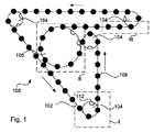
図1の概略平面図は、充填機械に配置されたように、本発明の第1実施形態に係る輸送システム100の基本的なレイアウトを示している。ピックアップ位置Iが存在し、そこでパッケージング容器は輸送システム100に導入され、そしてそこからパッケージング容器が充填位置II、本実施形態では充填カルーセルへと輸送される。領域IIでは、駆動要素として作用する駆動ホイールが示されており、以下で説明するように、充填カルーセルの一つの充填ステーションが各リセスのためにかつそれと整列状態で配置されている。駆動ホイール(したがって、充填カルーセル)の円周に対して接線方向に充填カルーセルを離れた後、パッケージング容器は密封位置IIIへと輸送され、その後、それらは、その後の取り扱いへと引き渡される。
The schematic plan view of FIG. 1 shows the basic layout of the
これらの目的のためにエンドレスコンベア102が、ガイドホイール104の形態のガイド要素および駆動ホイール106の形態の駆動要素によってガイドされて、閉じた経路に沿って延在する(本実施形態ではただ一つの駆動ホイールが使用されており、そしてそれは、それを駆動/推進するだけでなく、輸送システムをガイドする)。ベース要素108がエンドレスコンベア102の周囲に沿って割り当てられており、そしてベース要素108は、今度は、補助装備の取り付けのための取り付け位置/結合機構110(図2)を有していてもよい。
For these purposes, the
駆動ホイール106ならびにガイドホイール104は、ベース要素108が係合状態で嵌合するリセス(固定リセス)112ならびにエンドレスコンベアを収容する一つ以上の周方向溝(図1には図示せず)を備える。ベース要素108に配置されたパッケージング容器のための典型的な処理ステップは、いくつかを挙げれば、それらが殺菌され、それらが充填され、そしてそれらが密封されることであってもよい。ベース要素108がリセス112に係合的に嵌合する本構成は、ベース要素108の、したがってベース要素108によって直接または間接的に支持されるパッケージングデバイスの繊細な位置決めを可能とし、これは上記処理工程中の独特の利点である。これをさらに説明する一例は、駆動ホイール106は好ましくは充填カルーセルに対してそれと同心状に堅固に接続されてもよいということである。これによって、充填中の充填ステーションに関連したベース要素の位置は常に申し分ないことになる。リセス112が位置決めのために既に使用されているか/望まれるので、それらはまた推進のために使用されてもよい。輸送システム100全体は、ベース要素108に作用する駆動ホイール106によって駆動されてもよく、同ホイール108は、既に、例えば充填中、ベース要素108を位置決めする役割を果たしている。これによって追加の駆動手段の必要性はない。駆動ホイール106は、負荷および速度に応じて、適切なモーターによって駆動することができ、そして駆動部に直接接続されても、あるいはギアのセット、ベルトまたはその他の同様の手段を介して接続されてもよい。駆動ホイール106は、ギアとして作用し、ベース要素108を介して輸送システム100に対して推進力を伝達し、すなわち、各別個のベース要素は、それが駆動ホイールまたは対応する機構のリセスと係合するとき単一のギアとして機能する。負荷の集中を最小限にするためには最大直径を有するホイール上に駆動部を含むことが好ましいであろうし、これは、図示した充填システムに関しては、充填カルーセルに関連付けられたホイール106である。充填カルーセルのレイアウトは図1には詳細に開示されていないが、従来技術において利用可能な充填カルーセルのさまざまな例が存在し、そして本発明は充填システムなどの細部に関係しないので、そうした細部情報は不要であると考えられる。
The
隣接するベース要素108間の距離(中心間または「CC」)はピッチと呼ばれる。ピッチはエンドレスコンベア102の長さの周囲で一定でなければならないことに注目すべきであり、また、エンドレスコンベア102の長さはピッチの整数倍でなければならないことに注目すべきであり、そうでなければ、ベース要素を一定CC距離で配置することができないであろうし、しかもベース要素108はリセス112と一致しないであろう。
The distance between adjacent base elements 108 (between centers or "CC") is called the pitch. It should be noted that the pitch must be constant around the length of the
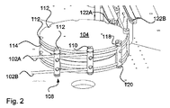
リセス112の使用は、それ自体、いくつかの利点を有する。例えば、システムの時間的調整およびキャリブレーション(較正)が非常に簡単である。(殺菌、加熱、充填、折り込み、引き渡しなどといった)実施されるプロセスは、たとえ微調整中のある段階においてパッケージがもちろん含まれ得る場合であっても、リセスに関連して較正され得る。いったん較正が実施されると、リセス112によってベース要素108が位置決めされる限り、動作はスムーズに実行される。これは、デリケートな較正処置および付加的なタイミングベルトを必要としない、ベース要素108を持たないエンドレスコンベア102で始まる別な方法でも作動し得る。なぜなら、システム自体は以下の方法でこれを実現するからである。エンドレスコンベア102に対してベース要素108を最初に取り付けるとき、(最大量のリセスを有する)駆動ホイール106あるいはその他のガイドホイール104はテンプレートとして使用されてもよい。このことは、図2のもう少し詳細な図を観察することでより容易に理解される。エンドレスコンベア102は機械のその経路内に配置されてもよく、そしてそれを位置決めするために駆動ホイール106に周囲溝114が存在してもよい。その後、ベース要素108は一つずつ配置され、リセス112によって位置決めされ、そしてそれらがリセスによって位置決めされるようにエンドレスコンベア102に締結される。このようにして、最初に配置されたベース要素108は、残りの全ての位置を決定し、そしてホイール104/106においてエンドレスコンベア102を送り出すことによって、コンベア102全体がベース要素108によって占有されるまでプロセスが繰り返され得る。この操作を実施するための実際的な手法は、まずエンドレスコンベア上にスライド可能に、いくつかのベース要素108を配置し、その後、徐々にエンドレスコンベアを送り出し、そしてそれらがホイール104/106のリセス内に配置されるようにベース要素108を配置しかつ締結することである。エンドレスコンベアの有効長さが重要であり、したがってガイド要素(ホイール)および駆動要素(ホイール)の位置決めは同様にデリケートであることは明らかである。しかしながら、これらのパラメータは容易に計算され、いったんそれが確定されると、別なデリケートでかつ重大な較正は、多かれ少なかれ、自動的に達成される。
The use of
特定の実施形態ではプロセスは以下の通りである。エンドレスコンベアのための原料は正確な長さに切断され、そして端部においてゴムまたはプラスチックのシースが内部ワイヤまたはコードが露出するように除去される。T−コネクター128(図3参照)がワイヤ上に通され、適所に溶接される。T−コネクター128は、それがT−コネクターを受けることができるように特定の設計を有するベース要素108に配置され、このベース要素は、図4に示すようなコネクター要素116と呼ぶことができ、そしてエンドレスコンベアの長さを調整する必要がある場合、C−シム130(C字形シム)が最も明白な方法で介在させられる。コネクター要素116は続いて組み立てられ、したがってエンドレスコンベアが形成されるが、このコンベアはパッケージング機械の経路内に配置され、残りのベース要素108によって完成する。修理あるいはメンテナンス中、あるいはその他の理由のために、コンベアの自由端部が結合される前に、エンドレスコンベアをその経路内に配置することが好ましいであろう。
In a particular embodiment the process is as follows: The raw material for the endless conveyor is cut to the correct length, and at the ends a rubber or plastic sheath is removed so that the internal wires or cords are exposed. The T-connector 128 (see FIG. 3) is threaded over the wire and welded in place. The T-
エンドレスコンベア102の長さは容易に計算され、そしてそれは実際には閉ループとして製造することができ、実際的な理由によって、それはコネクター要素116を含むことが好ましい。コンベアの自由端部を結合し、したがってエンドレスコンベア102を形成するコネクター要素116を有することにより、例えば既に説明したようにしてエンドレスコンベア102の有効長さを微調整することができるように、緊張機能を持たせることも可能である。エンドレスコンベア102の有効長さを変化させることにより、その張力は変更可能であり、そして長さのバランスをとることによって所定の圧力を達成することができる。実際には、エンドレスコンベアの長さ、あるいはむしろその経路の長さは、この長さは(後述する)ピッチによって固定されるので、可変パラメータではない。
The length of the
ベース要素108を伴って得られたエンドレスコンベア102は、コンベアとホイールとの間の、ならびにホイール間の同期は予測可能でかつ一定であるので、それ自身のタイミングベルトを構成する。簡単に言うと、本解決策は、同じ駆動部に接続された可動コンポーネント間のゼロドリフトをもたらす。何らかの理由で、駆動ホイールあるいはガイドホイールをテンプレートとして利用することが望まれない場合、設置目的のみのために使用されるべき直線(または湾曲)設計の別個のテンプレートが設けられてもよい。そうした別個のテンプレートは、好ましくは、ベース要素108の位置決めのための多数のリセスを有するべきであり、数が多いほど、より好ましい。
The
図3は、実際、コネクター要素116を示しているが、それはベース要素108のいくつかの有益な特徴を記述するために使用することができる。通常のベース要素はT−コネクター108に適応する必要がないという事実は別として、それは非常に類似したデザインを有していてもよい。それは、互いに取り外し可能に取り付けられる(図3においてはネジ136によって、但し、その他の手段が代わりに使用されてもよい)二つ以上の部品118および120を有することができる。貫通孔138がエンドレスコンベア102の収容のために配置される。それらが長手方向に仕切りを有するように各貫通孔138を配置することによって、それらは、所定の位置に通されることなく、すなわち貫通孔を通過する自由端を有する必要性を伴わずに、エンドレスコンベアがその中に配置可能であるようにアクセス可能となる。図示する実施形態では、各貫通孔138は長手方向中心面に沿って分割され(長手方向は貫通孔の長さ方向を意味し、すなわちそれが貫通孔内に配置された際のエンドレスコンベアの長手方向に対応する)、部品118,120のそれぞれに半円筒形の溝を残す。ベース要素が互いに取り付けられたとき、溝は対向する関係となり、貫通孔138を形成する。貫通孔の寸法は、ベース要素の二つの部品が組み合わされたとき、それらが両者間でエンドレスコンベアを締め付け、これによってベース要素108をそれに対して取り付けるようなものである。
FIG. 3 actually shows the
再び、その経路におけるエンドレスコンベアの配置を参照すると、一つ以上のガイドホイール104が移動可能に配置されてもよい。全てのガイドホイールは、それらはその目的を達成するために自由に回転できるので、明らかに移動可能に配置されるが、少なくとも一つは、輸送システムの組み立ておよび分解を容易にするために横方向への移動を許容するように配置されてもよく、これは、このコンテクストにおいて、移動可能が意味するものである。動作中のガイドホイール104の位置は、しかしながら、この位置がエンドレスコンベアのための経路長さを決定し、これが今度は上記ピッチによって繊細に設定されるので、高精度な位置であることに留意されたい。したがって、移動可能なガイドホイール104を動かすことは微調整を伴わない。移動可能なガイドホイールは、その経路に沿ってエンドレスコンベアを配置することを可能とする位置まで移動させられ、その後、移動可能なガイドホイールは固定位置へと戻るように移動させられる。この固定位置は、課題が与えられかつ類似の課題に精通した当業者には公知の適切な方法で停止要素によって保証されてもよい。
Again, referring to the placement of the endless conveyors along that path, one or
実際、エンドレスコンベアの所望の長さは、必要な経路長を計算することによって決定される。動作時のエンドレスコンベアにおける所望の張力(例えば500N)を与えれば、関連する伸びは、エンドレスコンベアのために使用される材料のための仕様書から計算することができる。これを知ることで、そしてコネクター要素116(該当する場合)および関連コンポーネントによって占有される長さを知ることで、エンドレスコンベアの適切な長さが準備され、その経路の周りに張られる。エンドレスコンベアが閉ループとして提供されない実施形態では、その端部はコネクター要素116において接合される。この後、コネクター要素は(例えばシムを使用して)正確な張力が実現されるまで調整される。エンドレスコンベアが正確な経路をたどるので、その長さは完全に調整され、そしてベース要素108は、エンドレスコンベアの調整後に配置され、取り付けられてもよいので、その位置は影響を受けない。
In fact, the desired length of the endless conveyor is determined by calculating the required path length. Given the desired tension in the endless conveyor in operation (eg 500N), the associated elongation can be calculated from the specifications for the materials used for the endless conveyor. By knowing this, and by knowing the length occupied by the connector element 116 (if applicable) and the associated components, the appropriate length of the endless conveyor is prepared and stretched around its path. In embodiments where the endless conveyor is not provided as a closed loop, its ends are joined at
ベース要素108の可能な設計が図2に示されている。二つの部品118,120から形成された中実円柱の全体的形状でベース要素108を提供することにより、それをエンドレスコンベア102に対して容易に締結(ボルト留めおよび摩擦による保持)することができる。設計は図4からより容易に理解され、コネクター要素116の内部は、コネクター128を嵌め込むために通常のベース要素とは僅かに異なっていてもよいが、全体構成は同じである。得られるベース要素108は、エンドレスコンベア102に対して対称的に配置され、それを左へあるいは右へとガイドするガイドホイール104との完全な適合性を与える。本実施例では、エンドレスコンベア102は、エンドレスコンベア102の長さ(あるいは長手)方向にベース要素108のための十分な安定性を保証する二つの要素102Aおよび102Bを備える。というのは、ベース要素108に対するエンドレスコンベアの二つの取り付けポイントは、この長さ方向に、それが傾くのを防止するからである。このベース要素108は、その円形断面および非複雑な設計に関して有益な特徴を有するが、明らかに、そうしたベース要素を設計する別な手法が存在する。
A possible design of the
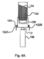
図4Aおよび図4Bの概略図を参照すると、ベース要素108に対して補助装備を取り付けるための結合手段あるいは結合機構110が示されている(これはまた図2に示されている)。そうした補助デバイスは、ほとんどの場合、パッケージング容器の位置決めのためのグリッパー要素が含むが、他のデバイスは除外されない。本実施形態では、輸送システム100は、充填機械の第1の端部でパッケージング容器を把持し、そして充填機械の第2の端部でパッケージング容器が解放されるまで把持を維持する。この連続的な把持は、充填プロセスの優れた制御を実現する。グリッパー要素の正確なレイアウトは、その一つ以上の実施形態に係る本発明の利点の理解のために重要ではない。そうした図面は、充填処理中の、すなわちそれらがカルーセルフィラーの円弧に沿って移動している間のパッケージング容器132を示しており、これは、基本コンポーネントおよびそれらの機能がいったん説明された後に詳しく説明される液位134の挙動を説明する。本実施形態では、結合手段110は円で示されているが、図2の実施形態ではそれはネジ開口によって提供され、それに対して、グリッパー要素126などの補助装備が螺着させることができる。結合手段110は、明らかに、多かれ少なかれ複雑であってもよい。グリッパー要素126は、ガイド手段124を含んでいてもよく、例えばグリッパー要素126の位置あるいは傾きを固定するために使用することができるガイドピンまたはガイドフランジを備えることができる。先に述べたように、二つ以上のエンドレスコンベアの使用は、既に述べたように長手方向においてベース要素108を安定化させることができるが、特にベース要素108が、かなりの重量を有する充填されたパッケージング容器を運ぶとき、横方向における傾きもまた回避されるべきである。パッケージング容器は、134で示される充填された製品の液位と共に、参照数字132で大まかに示されている。横方向の安定性のために、図2にカムトラックとして、そして図4Aおよび4Bにさらに大まかに示されたガイド機構122A,122Bもまた存在する。カムトラック122A,Bまたはカムトラックのセットはまた、グリッパー要素124の機能を発揮させるために使用することができる。そうした機能は本発明の一部ではないが、完全性のために、それは、平行に延在し、それぞれグリッパー要素124の機能に結合されたカム(またはピン)を案内する二つのカムトラックから構成されてもよい。カムトラックを開拡させるかあるいは収束させることによって、相対運動を生み出すことができ、今度はある動作に帰着する。例えば、ある動作は、パッケージング容器を解放するかあるいは把持するためにグリッパー要素を開閉することであってもよい。結合手段110がベース要素108の端部(図2に示す実施形態における上端または下端)の一方に配置されることが好ましく、あるいはそれは少なくとも関連する利点を有する。この位置は、それが邪魔にならないように、補助装備がベース要素108の上または下に、そして輸送システムの動作中にガイド手段あるいは駆動手段と係合するベース要素の一部の少なくとも外側に配置されることを可能とする。さらに、補助装備が、補助装備あるいはカップリングの一部が、左ターンあるいは右ターンの間にベース要素108と案内手段(例えばリセス112あるいはカムトラック122A,B)との間の係合と干渉しないように、ベース要素108の結合手段と同じ側に配置されることもまた好ましい。実際、左ターンのみあるいは右ターンのみが使用されるシステムを持つことが予見でき、したがってこの選択は、絶対的な必要性であるというよりも、本実施形態に結び付けられる。
With reference to the schematic views of FIGS. 4A and 4B, a coupling means or
ガイドシステム(例えば、ガイドピンおよびカムトラック)の特定の使用が、充填ステップに関連して利用されてもよい。図1および図2に示されたシステムにおいて、充填は、IIで示された領域における充填カルーセル内で実施され、この場合、充填ノズル(図示せず)が充填カルーセルの周囲を取り囲む複数の位置に配置される。一般的な技術が、通常、例えばボトル充填において使用され、詳細についてはさらに詳しく説明しない。特定の実施形態では、パッケージング容器が把持され、充填カルーセルを経て輸送される際に、適切な充填がなされ得るようにその開口が充填ノズルに関して適切な方式で整列させられるという意味で、各充填ノズルはリセス112と整列させられる。
Specific uses of guide systems (eg, guide pins and cam tracks) may be utilized in connection with the filling step. In the system shown in FIGS. 1 and 2, filling is performed within the filling carousel in the region indicated by II, in which case the filling nozzles (not shown) are located at multiple locations surrounding the filling carousel. Be placed. Common techniques are usually used, for example in bottle filling, and no further details will be given. In certain embodiments, each filling means that as the packaging container is gripped and transported through the filling carousel, its openings are properly aligned with respect to the filling nozzles so that proper filling can be made. The nozzle is aligned with the
カルーセルフィラーに関して、充填される製品は、それがノズルを離れるとき、いくつかのポイントにおいて拘束されない(すなわち求心力によって拘束されない)ので求心力は問題となることがあり、そして非拘束状態では、拘束回転運動を脱する物理的ボディがそうであるように、それは接線方向をたどる。回転速度、パッケージング容器までの距離等に応じて、パッケージング容器に対するインパクトのポイントは変化し得る。ノズルは、充填カルーセルが回転しないか第1の速度で回転する場合にスプラッシュおよび泡の発生を最小限に抑えた対称的充填のためにパッケージング容器と完全に整列させることができる。しかしながら、回転速度が変更される(回転を開始するか第1の速度とは異なる第2の速度で回転する)とき、充填パターンは歪められることがあり、スプラッシュおよび発泡の増大につながる。これはまた、第1の製品のための設定は第2の製品のために最適ではないかもしれないために、充填されるべき製品に依存し得る。本輸送システムは、比較的容易にこの問題を解決できる。ガイドシステム(122A,B)(ピンおよびカムトラック、またはその他のカム/カムフォロアシステム)を使用することによって、図4Bに示すように、グリッパー要素124の傾きを調整することができる。それが充填カルーセルをたどるときエンドレスコンベアの各側に一つのカムトラックが存在する場合(例えば半径方向内側に一つのカムトラックおよび半径方向外側に一つのカムトラック)、これらのカムトラックは、エンドレスコンベア102の移動の面に対して垂直な方向に異なる高さで配置されてもよく、グリッパー要素はベース要素108に対してヒンジ式カップリング110によって結合されてもよく、これによってグリッパー要素は水平線に対して傾斜したポジションを呈するようになる。カムトラック122A,Bの高さは可変であってさえよい。変動は、油圧システム、ガイド/サーボシステムまたは課題が与えられた当業者には明らかな他の適切な方法によって実行することができる。グリッパー要素によって運搬されるパッケージング容器の傾きは、したがって、パッケージング容器の基準システムにおいて、充填される製品が容器内に本質的に真っ直ぐに(または特定の充填パターンの達成に適したその他の方式で)落下するように、求心力を考慮して調整することができる。図4Bにおいて、これは対称的な液位134によって示されている。
With respect to the carousel filler, centripetal force can be an issue because the product to be filled is not constrained at some point (ie, not constrained by centripetal force) as it leaves the nozzle, and in the unrestrained state, constrained rotational motion. It follows a tangential direction, as is the physical body that escapes. The point of impact on the packaging container can change depending on the rotation speed, the distance to the packaging container, and the like. The nozzle can be perfectly aligned with the packaging vessel for symmetrical filling with minimal splash and foam generation when the filling carousel does not rotate or rotates at a first speed. However, when the rotation speed is changed (starting rotation or rotating at a second speed different from the first speed), the filling pattern can be distorted, leading to increased splash and foaming. It may also depend on the product to be filled, as the settings for the first product may not be optimal for the second product. This transportation system can solve this problem relatively easily. By using a guide system (122A, B) (pin and cam track, or other cam / cam follower system), the tilt of the
充填プロセスを継続し、そしてまたパッケージング容器内に充填された製品の慣性に留意すると、液跳ねを最小限に抑えるために正または負の加速度(リタデーション)を回避するか少なくとも最小化することが好ましい。これを達成するために、図1に示されたもののような一つ以上の実施形態においては、パッケージング容器は、それが充填中にたどっている円に関連した接線方向に充填カルーセルを離れることが好ましい。なぜなら、これは、充填された製品が左拘束をたどろうとする方向であるからである。そのような経路の利点によって、それを経てパッケージが充填される開口部のサイズを増大させることができる。求心力を補償するためのパッケージング容器の傾きは、全ての製品および全ての速度において不要であるが、例えば求心力を考慮するためにパッケージング容器が傾斜させられている実施形態では、カムトラックは、パッケージング容器134が充填カルーセルを離れるとき、徐々にかつ滑らかに傾斜を減少させるように構成されてもよい。
Continuing the filling process, and also paying attention to the inertia of the product packed in the packaging container, can avoid or at least minimize positive or negative acceleration (retalysis) to minimize splashing. preferable. To achieve this, in one or more embodiments, such as those shown in FIG. 1, the packaging container leaves the filling carousel in the tangential direction associated with the circle it is following during filling. Is preferable. This is because the filled product tends to follow the left constraint. The advantage of such a route can increase the size of the opening through which the package is filled. Tilt of the packaging vessel to compensate for centripetal force is not required for all products and all speeds, but in embodiments where the packaging vessel is tilted to account for centripetal force, for example, the cam track The
図1において、そこでパッケージング容器を充填することが可能な位置(リセス112および対応するノズルなど)を規定するために充填ステーションの用語を使用して、各所与の時刻に、ある数の空の充填ステーションが存在することは明らかである。ある数の「デッド」充填ステーションが存在することになる。と言うのは、輸送システムが充填カルーセルに入り、出て行くことを可能とするためにある程度の余地が必要であるからである(図1の領域II参照)。効率性の観点から、デバイスの使用を最大化するために、空の充填ステーションの数を最小限にすることが好ましい。輸送システム、エンドレスコンベア102および関連するベース要素108が鋭角であるいは曲線をたどって充填カルーセルを離れることを可能とすることによって空の充填ステーションの数を減らすことができ、そしてある実施形態に関して図1に示すような接線方向の出口の使用が好ましい場合でさえ、領域IIは充填カルーセルの高い回転速度を可能とし、これは全体として充填機械の効率のために有益である。本実施形態では接線方向出口が好まれる。
In FIG. 1, a number of empty at each given time, using filling station terminology to define where the packaging container can be filled (such as
いったん接線方向に充填カルーセルを離れると、輸送システム、したがってその中に配置されたパッケージング容器は、そこでパッケージング容器が密閉される密封ステーション(図1の領域III)へと直線経路をたどる。さまざまな種類のボトルに関して、密封は開放端内へのキャップ(キャッピング)またはコルクの配置を伴ってもよく、そして紙ベースパッケージング容器に関して、それは、パッケージング容器の開放端の横断シールの配置を伴ってもよい。密封された後、パッケージング容器は輸送システムから取り出すことができ、そして輸送システムは、新たなパッケージング容器を受け取るためのピックアップ位置へと戻るその経路をたどることができる。一般的な解決策では、パッケージング容器は、折り込み(パッケージングラミネートから形成されたパッケージング容器の場合)、二次パッケージへの包装(例えばカートンまたは枠組箱)などといった、さらなる処理のために連続的な輸送システムへと引き渡される。連続した輸送システムは、本発明のものと、あるいはその実施形態と同じ種類のものであってもよく、そして引き渡しを実施する理由は、パッケージング容器が密封された後に必要とされるよりも充填機内部の衛生レベルが高く、したがって可能な限り最高の程度まで充填機械を分離させることが好ましいというものである。 Once tangentially off the filled carousel, the transport system, and thus the packaging container placed therein, follows a straight path to a sealing station (Region III in FIG. 1) where the packaging container is sealed. For various types of bottles, the seal may involve the placement of a cap (capping) or cork within the open end, and for paper-based packaging containers, it arranges the cross-seal on the open end of the packaging container. May be accompanied. After being sealed, the packaging container can be removed from the shipping system, and the shipping system can follow its path back to the pick-up position for receiving the new packaging container. In a common solution, the packaging container is continuous for further processing, such as folding (in the case of packaging containers formed from packaging laminates), packaging into secondary packages (eg cartons or framing boxes), etc. Handed over to a typical transportation system. The continuous transport system may be of the same type as that of the present invention, or an embodiment thereof, and the reason for carrying out the delivery is to fill more than required after the packaging container is sealed. The hygiene level inside the machine is high, so it is preferable to separate the filling machine to the highest possible degree.
この引き渡しならびにピックアップ中の引き渡しの間、状況に応じて、グリッパー手段は、解放あるいは把持動作を実施するためにカムまたはサーボモータによって制御することができる。本発明のシステムは、引き渡しを機械的に時間調整することを可能とし、高い信頼性と共に継続的かつ予測可能な性能を実現する。 During this delivery and delivery during pickup, depending on the circumstances, the gripper means can be controlled by a cam or servomotor to perform a release or grip operation. The system of the present invention allows delivery to be mechanically timed to achieve high reliability and continuous and predictable performance.
本発明を一つ以上の好ましい実施形態を参照して説明してきたが(当該実施形態は本発明の完全な開示をなすためにかなり詳細に記述した)、そうした実施形態は単なる例示であり、限定あるいは本発明の全ての態様の網羅的列挙を体現することを意図していない。したがって、本発明の範囲は、特許請求の範囲によってのみ規定される。さらに、数多くの変更を、本発明の趣旨および原理から逸脱することなく、そうした細部に関して実施できることは当業者にとって自明である。 Although the present invention has been described with reference to one or more preferred embodiments (the embodiments have been described in considerable detail for the full disclosure of the invention), such embodiments are merely exemplary and limited. Alternatively, it is not intended to embody an exhaustive enumeration of all aspects of the invention. Therefore, the scope of the present invention is defined only by the claims. Moreover, it will be apparent to those skilled in the art that numerous modifications can be made with respect to such details without departing from the spirit and principles of the present invention.
100 輸送システム
102 エンドレスコンベア
104 ガイドホイール(ガイド要素)
106 駆動ホイール(駆動要素)
108 ベース要素
110 結合手段
112 リセス
114 周囲溝
116 コネクター要素
118,120 部品
122A,B カムトラック
124,126 グリッパー要素
128 コネクター
130 シム
132 パッケージング容器
134 液位
138 貫通孔
100
106 Drive wheel (drive element)
108
Claims (21)
前記少なくとも一つの駆動要素(106)は、前記ベース要素(108)を受けるためのリセス(112)を備え、
前記ベース要素(108)は前記エンドレスコンベア(102)の長さに沿って任意の位置に開放可能かつスライド可能に取り付け及び再取り付けが可能であり、動作位置において前記ベース要素(108)は前記エンドレスコンベアに対して堅固に取り付けられて前記リセス(112)の位置と一致させられる、輸送システム。 A transport system (100) for transporting packaging containers through a series of processing steps, at least one endless conveyor (102) that follows a path that includes a guide element (104) and at least one drive element (106). And a base element (108) that is allocated along the length of the endless conveyor and carries the packaging container.
The at least one driving element (106) comprises a recess (112) for receiving the base element (108).
The base element (108) can be opened and slidably attached and reattached to any position along the length of the endless conveyor (102), and the base element (108) is endless at the operating position. A transport system that is tightly attached to the conveyor and aligned with the recess (112) position.
前記機械を通過する経路をたどる少なくとも一つのエンドレスコンベアを配置するステップであって、前記経路はリセスを有するガイド要素を含んでいる、ステップと、
前記パッケージング容器を運搬するベース要素あるいはその少なくとも一部を前記リセス内に連続的に配置するステップと、
隣接するベース要素間の正確なピッチを得るために前記ガイド要素を用いて前記エンドレスコンベアに対して前記ベース要素を取り付けるステップと、
を備え、
前記ベース要素は前記エンドレスコンベアの長さに沿って任意の位置に開放可能かつスライド可能に取り付け及び再取り付けが可能であり、動作位置において前記ベース要素は前記エンドレスコンベアに対して堅固に取り付けられて前記リセスの位置と一致させられる、
方法。 A method for arranging a transportation system for packaging containers on a machine for processing packaging containers.
A step of arranging at least one endless conveyor that follows a path through the machine, wherein the path includes a guide element having a recess.
A step of continuously arranging the base element or at least a part thereof carrying the packaging container in the recess.
The step of attaching the base element to the endless conveyor using the guide element to obtain an accurate pitch between adjacent base elements.
Equipped with a,
The base element can be opened and slidably attached and reattached to any position along the length of the endless conveyor, and in the operating position the base element is firmly attached to the endless conveyor. Matched with the recess position,
Method.
Applications Claiming Priority (3)
| Application Number | Priority Date | Filing Date | Title |
|---|---|---|---|
| SE1350772-8 | 2013-06-25 | ||
| SE1350772 | 2013-06-25 | ||
| PCT/EP2014/062536 WO2014206784A1 (en) | 2013-06-25 | 2014-06-16 | System and method for transporting packaging containers |
Publications (3)
| Publication Number | Publication Date |
|---|---|
| JP2016528114A JP2016528114A (en) | 2016-09-15 |
| JP2016528114A5 JP2016528114A5 (en) | 2017-07-27 |
| JP6754692B2 true JP6754692B2 (en) | 2020-09-16 |
Family
ID=51033140
Family Applications (1)
| Application Number | Title | Priority Date | Filing Date |
|---|---|---|---|
| JP2016522384A Expired - Fee Related JP6754692B2 (en) | 2013-06-25 | 2014-06-16 | Systems and methods for transporting packaging containers |
Country Status (9)
| Country | Link |
|---|---|
| US (1) | US20160368638A1 (en) |
| EP (1) | EP3013697B1 (en) |
| JP (1) | JP6754692B2 (en) |
| KR (1) | KR20160022882A (en) |
| CN (1) | CN105324311B (en) |
| BR (1) | BR112015032253B1 (en) |
| MX (1) | MX2015017097A (en) |
| RU (1) | RU2649859C2 (en) |
| WO (1) | WO2014206784A1 (en) |
Families Citing this family (2)
| Publication number | Priority date | Publication date | Assignee | Title |
|---|---|---|---|---|
| ZA201904027B (en) * | 2018-06-22 | 2022-04-28 | Dale Holdings Pty Ltd | Positive drive conveyor |
| CN110127142B (en) * | 2019-05-28 | 2023-12-05 | 海南中橡科技有限公司 | Automatic packaging production line for natural rubber |
Family Cites Families (16)
| Publication number | Priority date | Publication date | Assignee | Title |
|---|---|---|---|---|
| US2405530A (en) * | 1943-08-28 | 1946-08-06 | John O Sullivan | Conveyer construction |
| SE375961B (en) * | 1973-03-01 | 1975-05-05 | U Henrekson | |
| JP3064486B2 (en) * | 1991-06-04 | 2000-07-12 | 株式会社東芝 | Driving force transmission device, manufacturing method thereof, and extension structure provided with driving force transmission device |
| JP2886104B2 (en) * | 1995-03-17 | 1999-04-26 | のむら産業株式会社 | Packaging equipment |
| DE19816239A1 (en) * | 1998-04-11 | 1999-10-14 | Krones Ag | Device for introducing and / or discharging containers into or from a treatment room |
| US6688451B2 (en) * | 2000-04-05 | 2004-02-10 | Stephen J. Derby | Multi-head robot system and method of use |
| JP4662100B2 (en) * | 2001-04-04 | 2011-03-30 | 東洋自動機株式会社 | Bag transfer device in bagging and packaging machine |
| US7278531B2 (en) * | 2004-06-29 | 2007-10-09 | Hartness International, Inc. | Flexible conveyor and connection elements |
| US7331156B2 (en) * | 2004-06-29 | 2008-02-19 | Hartness International, Inc. | System for securely conveying articles and related components |
| EP1915306A1 (en) * | 2005-07-29 | 2008-04-30 | Ferag AG | Conveying system |
| DE102006062530B4 (en) * | 2006-12-29 | 2016-06-23 | Siegmund Kumeth | Transport system for workpieces |
| FR2948315B1 (en) * | 2009-07-21 | 2015-04-24 | Sidel Participations | DEVICE FOR CONVEYING CONTAINERS IN A HEATING UNIT |
| CN202089530U (en) * | 2011-04-09 | 2011-12-28 | 李志杰 | Teeth cable type bucket elevator |
| ES2395263B1 (en) * | 2011-05-12 | 2013-12-23 | Mespack, Sl | CARRUSEL FOR AUTOMATIC PACKAGING MACHINE OF HORIZONTAL TYPE. |
| CN202864264U (en) * | 2012-10-26 | 2013-04-10 | 齐齐哈尔轨道交通装备有限责任公司 | Conveying device |
| CN202924253U (en) * | 2012-11-27 | 2013-05-08 | 汕头市新青罐机有限公司 | Packaging container conveying device |
-
2014
- 2014-06-16 EP EP14734028.5A patent/EP3013697B1/en not_active Not-in-force
- 2014-06-16 BR BR112015032253-0A patent/BR112015032253B1/en not_active IP Right Cessation
- 2014-06-16 RU RU2016101977A patent/RU2649859C2/en active
- 2014-06-16 KR KR1020167001392A patent/KR20160022882A/en not_active Application Discontinuation
- 2014-06-16 WO PCT/EP2014/062536 patent/WO2014206784A1/en active Application Filing
- 2014-06-16 JP JP2016522384A patent/JP6754692B2/en not_active Expired - Fee Related
- 2014-06-16 MX MX2015017097A patent/MX2015017097A/en unknown
- 2014-06-16 US US14/901,423 patent/US20160368638A1/en not_active Abandoned
- 2014-06-16 CN CN201480036762.5A patent/CN105324311B/en not_active Expired - Fee Related
Also Published As
| Publication number | Publication date |
|---|---|
| CN105324311A (en) | 2016-02-10 |
| RU2649859C2 (en) | 2018-04-05 |
| CN105324311B (en) | 2018-05-01 |
| EP3013697B1 (en) | 2017-08-23 |
| EP3013697A1 (en) | 2016-05-04 |
| WO2014206784A1 (en) | 2014-12-31 |
| KR20160022882A (en) | 2016-03-02 |
| US20160368638A1 (en) | 2016-12-22 |
| MX2015017097A (en) | 2016-03-16 |
| RU2016101977A (en) | 2017-07-26 |
| JP2016528114A (en) | 2016-09-15 |
| BR112015032253A2 (en) | 2017-07-25 |
| BR112015032253B1 (en) | 2021-04-13 |
Similar Documents
| Publication | Publication Date | Title |
|---|---|---|
| EP1651555B1 (en) | Capping and nitrogen dosing apparatus | |
| US20070000570A1 (en) | Beverage bottling plant for filling and closing beverage bottles with a packaging device for packaging beverage bottles | |
| JP6612977B2 (en) | Mounting unit for attaching the lid to the container | |
| EP1864942B1 (en) | Container transportation line for bottling plants | |
| US10287118B2 (en) | Apparatus and method for feeding carton blanks from a magazine to carriers | |
| US10815017B2 (en) | Apparatus for capping a container | |
| US10351281B2 (en) | Method for conveying in a packaging line flexible packaging held suspended, device suitable for implementing said method, and machine comprising said device | |
| JP2017509558A (en) | Unit for attaching the lid of the opening device | |
| JP6754692B2 (en) | Systems and methods for transporting packaging containers | |
| US10967996B2 (en) | Method of, and an applying head for, applying a lid onto a container | |
| US11370623B2 (en) | Devices and methods for supplying lids to a can seamer | |
| KR20090064653A (en) | Molding divice of carton for bottles | |
| EP1215124A1 (en) | Unit for applying opening devices to packages of pourable food products | |
| JP6847920B2 (en) | Label fitting system | |
| US10532901B2 (en) | Device and method for aligning blanks in a magazine holding a number of blanks, and an apparatus and method for fetching a blank from a magazine holding a number of blanks | |
| CN106395715A (en) | Machine for filling containers | |
| CN118339091A (en) | Container transport system for transporting containers, handling device and method for transporting containers | |
| CN110891884A (en) | Processing device and method for processing a singulated package | |
| JP2017024768A (en) | Film fitting device |
Legal Events
| Date | Code | Title | Description |
|---|---|---|---|
| A521 | Request for written amendment filed |
Free format text: JAPANESE INTERMEDIATE CODE: A523 Effective date: 20170614 |
|
| A621 | Written request for application examination |
Free format text: JAPANESE INTERMEDIATE CODE: A621 Effective date: 20170614 |
|
| A131 | Notification of reasons for refusal |
Free format text: JAPANESE INTERMEDIATE CODE: A131 Effective date: 20180827 |
|
| A601 | Written request for extension of time |
Free format text: JAPANESE INTERMEDIATE CODE: A601 Effective date: 20181126 |
|
| RD02 | Notification of acceptance of power of attorney |
Free format text: JAPANESE INTERMEDIATE CODE: A7422 Effective date: 20181126 |
|
| A521 | Request for written amendment filed |
Free format text: JAPANESE INTERMEDIATE CODE: A523 Effective date: 20190125 |
|
| A131 | Notification of reasons for refusal |
Free format text: JAPANESE INTERMEDIATE CODE: A131 Effective date: 20190402 |
|
| A601 | Written request for extension of time |
Free format text: JAPANESE INTERMEDIATE CODE: A601 Effective date: 20190624 |
|
| A521 | Request for written amendment filed |
Free format text: JAPANESE INTERMEDIATE CODE: A523 Effective date: 20190816 |
|
| A02 | Decision of refusal |
Free format text: JAPANESE INTERMEDIATE CODE: A02 Effective date: 20200107 |
|
| A521 | Request for written amendment filed |
Free format text: JAPANESE INTERMEDIATE CODE: A523 Effective date: 20200410 |
|
| A911 | Transfer to examiner for re-examination before appeal (zenchi) |
Free format text: JAPANESE INTERMEDIATE CODE: A911 Effective date: 20200417 |
|
| TRDD | Decision of grant or rejection written | ||
| A01 | Written decision to grant a patent or to grant a registration (utility model) |
Free format text: JAPANESE INTERMEDIATE CODE: A01 Effective date: 20200804 |
|
| A61 | First payment of annual fees (during grant procedure) |
Free format text: JAPANESE INTERMEDIATE CODE: A61 Effective date: 20200824 |
|
| R150 | Certificate of patent or registration of utility model |
Ref document number: 6754692 Country of ref document: JP Free format text: JAPANESE INTERMEDIATE CODE: R150 |
|
| LAPS | Cancellation because of no payment of annual fees |