JP6752254B2 - Information processing device, information processing method - Google Patents
Information processing device, information processing method Download PDFInfo
- Publication number
- JP6752254B2 JP6752254B2 JP2018151961A JP2018151961A JP6752254B2 JP 6752254 B2 JP6752254 B2 JP 6752254B2 JP 2018151961 A JP2018151961 A JP 2018151961A JP 2018151961 A JP2018151961 A JP 2018151961A JP 6752254 B2 JP6752254 B2 JP 6752254B2
- Authority
- JP
- Japan
- Prior art keywords
- tomographic image
- information
- dimensional
- distance
- information processing
- Prior art date
- Legal status (The legal status is an assumption and is not a legal conclusion. Google has not performed a legal analysis and makes no representation as to the accuracy of the status listed.)
- Active
Links
Images


Description
本発明は、断層像を取り扱う技術に関するものである。 The present invention relates to a technique for handling a tomographic image.
医療の分野において、医師は、複数のモダリティで撮像した医用画像(被検体内部の3次元的な情報を表す3次元画像データ)や、異なる日時に撮像した医用画像を用いて診断を行っている。複数種類の医用画像を診断に利用するためには、夫々の医用画像において注目する病変部等の部位(注目部位、注目病変部)を対応付ける(同定する)ことが重要である。そのため、医師は、一方の医用画像上で指摘されている注目病変部の画像を見ながら、病変部の形状やその周辺部の見え方等の類似性を手がかりにして、その病変部に対応する部位(対応部位,対応病変部)を他方の医用画像から探索するという作業を行っている。 In the medical field, doctors make a diagnosis using medical images (three-dimensional image data representing three-dimensional information inside a subject) taken with multiple modalities and medical images taken at different dates and times. .. In order to use a plurality of types of medical images for diagnosis, it is important to associate (identify) a site such as a lesion of interest (site of interest, lesion of interest) in each medical image. Therefore, the doctor responds to the lesion by looking at the image of the lesion of interest pointed out on one of the medical images and using the similarity in the shape of the lesion and the appearance of the peripheral portion as a clue. We are working to search for the site (corresponding site, corresponding lesion) from the other medical image.
乳腺科では、伏臥位で撮像した乳房のMRI画像上で病変部等が指摘された後に、仰臥位による超音波検査で超音波断層画像上における対応病変部を探索して(同定して)診断を行うことがある。しかし、被検体である乳房が柔らかく、かつ、体位の差異が大きいため、病変部の位置や見え方が大きく変化してしまうという課題がある。そのため、対応病変部の探索は容易ではなく、何らかのコンピュータ支援による負荷の軽減が求められている。 In the mammary gland department, after the lesions are pointed out on the MRI image of the breast taken in the prone position, the corresponding lesions on the ultrasonic tomographic image are searched (identified) by ultrasonography in the supine position for diagnosis. May be done. However, since the breast as the subject is soft and the difference in body position is large, there is a problem that the position and appearance of the lesion portion are significantly changed. Therefore, it is not easy to search for the corresponding lesion, and it is required to reduce the load by some kind of computer support.
特許文献1では、伏臥位から仰臥位への乳房の変形推定を行う技術が示されている。この変形推定結果を用いれば、仰臥位における病変部の位置を推定し、推定位置を超音波探触子操作の支援情報として提示できる。また、特許文献2では、乳房の単純X線画像から乳頭位置を自動で抽出し、そこから一定の範囲内に含まれる画像中の領域を該画像中に描画する技術が示されている。
特許文献1に記載の方法を用いる場合、有限要素法等の変形シミュレーションの計算が必要なため、操作者(医師)は計算が終了するまで待たなくてはならないという課題がある。また、変形シミュレーションを実施するために操作者が入力すべき計測情報が幾つか存在するが、その入力の手間が許容されない場合があるという課題がある。さらに、乳房の変形を正確に推定すること自体が容易ではないという課題も残されている。また、特許文献2に記載の方法では、被検体の特徴点から一定の範囲内の領域を知ることができるが、それは画像中に特徴点が含まれる断面のみであるため、任意の断面でその領域を知ることができない。
When the method described in
本発明はこのような問題に鑑みてなされたものであり、画像中で病変部等を探索する際の支援情報を、多くの計測情報を用いずに簡易な計算のみで導出して提示する為の技術を提供する。 The present invention has been made in view of such a problem, and is for deriving and presenting support information for searching a lesion or the like in an image only by a simple calculation without using a lot of measurement information. Providing technology.
本発明の一様態によれば、超音波探触子を用いて撮影された被検体の断層画像を取得する取得手段と、
前記超音波探触子の位置姿勢を表す情報を取得する位置姿勢取得手段と、
前記超音波探触子の位置姿勢を表す情報を用いて、前記被検体上の基準点の三次元位置を表す情報を取得する基準点位置取得手段と、
前記超音波探触子の位置姿勢を表す情報と前記基準点の三次元位置を表す情報に基づいて、前記基準点から所定の三次元距離だけ離間した部分に対応する前記断層画像中の複数の箇所を特定する特定手段と、
前記断層画像に前記複数の箇所を示す情報を合成した合成画像を生成する生成手段と
を備えることを特徴とする。
According to the uniform state of the present invention, an acquisition means for acquiring a tomographic image of a subject photographed by using an ultrasonic probe, and an acquisition means.
A position / orientation acquisition means for acquiring information representing the position / orientation of the ultrasonic probe, and
A reference point position acquisition means for acquiring information representing a three-dimensional position of a reference point on the subject by using information indicating the position and orientation of the ultrasonic probe .
Based on the information representing the position and orientation of the ultrasonic probe and the information representing the three-dimensional position of the reference point, a plurality of tomographic images corresponding to portions separated by a predetermined three-dimensional distance from the reference point. Specific means to identify the location and
It is characterized by comprising a generation means for generating a composite image in which information indicating the plurality of locations is combined with the tomographic image.
本発明の構成によれば、画像中で病変部等を探索する際の支援情報を、多くの計測情報を用いずに簡易な計算のみで導出して提示することができる。 According to the configuration of the present invention, support information for searching for a lesion or the like in an image can be derived and presented only by a simple calculation without using a lot of measurement information.
以下、添付図面を参照し、本発明の好適な実施形態について説明する。なお、以下説明する実施形態は、本発明を具体的に実施した場合の一例を示すもので、特許請求の範囲に記載の構成の具体的な実施例の1つである。 Hereinafter, preferred embodiments of the present invention will be described with reference to the accompanying drawings. In addition, the embodiment described below shows an example when the present invention is concretely implemented, and is one of the specific examples of the configuration described in the claims.
[第1の実施形態]
本実施形態に係る情報処理システムは、MRI等のモダリティで取得した画像上で病変部等の注目部位が指摘された後に、超音波検査で超音波断層画像上における対応部位を探索(同定)して診断する場合に、その探索の支援情報を操作者に提示するものである。本システムは、乳房を検査対象とした場合、伏臥位・仰臥位といった体位の違いに関わらず、乳頭から病変部等の注目部位までの3次元距離(乳頭注目部位間距離)が保たれる傾向にあるという知見に基づいて、対応部位が存在する可能性の高い場所を超音波断層像上に提示する。また、乳頭から画像上の各点までの距離が把握できるような情報を超音波断層像上に表示することで、超音波断層画像上での対応部位の探索を容易にする。以下、本実施形態に係る情報処理システムについて説明する。
[First Embodiment]
The information processing system according to the present embodiment searches (identifies) the corresponding site on the ultrasonic tomographic image by ultrasonic examination after the attention site such as the lesion is pointed out on the image acquired by the modality such as MRI. The support information for the search is presented to the operator when making a diagnosis. This system tends to maintain the three-dimensional distance (distance between nipple attention sites) from the nipple to the attention site such as the lesion regardless of the difference in body position such as prone position and supine position when the breast is examined. Based on the finding that it is located in, the location where the corresponding site is likely to exist is presented on the ultrasonic tomographic image. In addition, by displaying information on the ultrasonic tomographic image so that the distance from the papilla to each point on the image can be grasped, it is easy to search for the corresponding part on the ultrasonic tomographic image. Hereinafter, the information processing system according to this embodiment will be described.
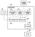
先ず、本実施形態に係る情報処理システムの機能構成例について、図1のブロック図を用いて説明する。図1に示す如く、本実施形態に係る情報処理システムは、データサーバ160、情報処理装置100、医用画像収集装置170、表示部180、を有する。
First, an example of the functional configuration of the information processing system according to the present embodiment will be described with reference to the block diagram of FIG. As shown in FIG. 1, the information processing system according to the present embodiment includes a
先ず、データサーバ160について説明する。データサーバ160は、観察対象である被検体の基準点(乳頭)から注目部位までの3次元距離(基準点注目部位間距離)等の情報を保持しており、これを情報処理装置100へと出力する。データサーバ160が保持する基準点注目部位間距離は、同一被検体を撮影したMRI画像等の他の3次元の医用画像から予め算出された数値である。この値は、例えばMRI画像から画像処理によって基準点の位置(乳頭位置)を検出し、操作者が同画像上で指摘した注目部位の位置との間の3次元距離を算出する処理を不図示の画像処理システムが実行することで取得できる。
First, the
なお、図1ではデータサーバ160は情報処理装置100の外部装置として示しているが、情報処理装置100内の機器としてもよく、例えば、情報処理装置100に内蔵されているハードディスクなどの機器であっても構わない。
Although the
次に、医用画像収集装置170について説明する。本実施形態では、医用画像収集装置170は超音波画像診断装置であるものとして説明する。医用画像収集装置170は、被検体の超音波断層画像(断層像)を実時間で撮像する。医用画像収集装置170によって撮像された各フレームの超音波断層画像は順次、断層画像取得部110を介して情報処理装置100に入力される。また、医用画像収集装置170は、不図示の超音波探触子の空間中の位置姿勢(3次元位置姿勢)を実時間で計測するためのセンサシステムを有している。このセンサシステムによって計測された超音波探触子の位置姿勢は順次、位置姿勢取得部120を介して情報処理装置100に入力される。超音波探触子の位置姿勢を計測するためのセンサシステムには様々な構成が考えられる。例えば、超音波探触子の画像を実時間で撮像し、該画像から超音波探触子の位置姿勢を計算により求めても構わないし、磁気センサや超音波センサ、光学式センサを用いた周知の計測方法で計測しても構わない。
Next, the medical image collecting
次に、情報処理装置100について説明する。情報処理装置100には、例えば、一般のPC(パーソナルコンピュータ)などを適用することもできるし、専用のハードウェアを適用することもできる。
Next, the
基準距離取得部105は、データサーバ160から送出される基準点注目部位間距離を、基準距離として取得する。断層画像取得部110は上記の通り、医用画像収集装置170から順次送出される超音波断層画像を後段の画像生成部140に転送する。位置姿勢取得部120は上記の通り、医用画像収集装置170から順次送出される位置姿勢を後段の画像生成部140に転送する。
The reference
基準点位置取得部130は、操作者の指示に基づき、超音波探触子の位置姿勢を利用して、空間中における基準点の位置を取得する。
The reference point
画像生成部140は、基準距離と、基準点の位置と、超音波探触子の位置姿勢と、に基づいて後述する計算処理を行うことで、基準点を中心とし且つ基準距離を半径とする球を、超音波断層画像に対応する断層面で切り取った部分(円)を算出する。そして画像生成部140は、この算出した円のうち超音波断層画像に含まれる部分(円弧)に関する情報を超音波断層画像上に重畳(合成)して、表示制御部150に対して送出する。
The
表示制御部150は、画像生成部140から送出された合成画像、即ち、超音波断層画像上に円弧に関する情報が重畳された画像を、表示部180に送出することで、該画像を表示部180に表示させる。
The
表示部180は、CRTや液晶画面などにより構成されており、情報処理装置100による処理結果を画像や文字などでもって表示する。表示部180は例えば、後述する合成画像やGUI(グラフィカルユーザインターフェース)などを表示することができる。
The
ここで、情報処理装置100を構成する各機能部は何れもハードウェアで構成しても良いが、その一部をソフトウェア(コンピュータプログラム)で構成しても良い。この場合、このソフトウェアは、情報処理装置100が有する制御部によって実行されることで対応する機能が実現されることになる。また、情報処理装置100を構成する各機能部のうち1以上を外部の独立した機器としても構わない。もちろん、情報処理装置100を構成する各機能部をソフトウェアで実現させても良い。
Here, each functional unit constituting the
本実施形態では、情報処理装置100を構成する各機能部は何れもソフトウェアで構成するものとして説明する。この場合、情報処理装置100には、図2に示すようなハードウェア構成を有するコンピュータを適用することができる。
In the present embodiment, each functional unit constituting the
CPU1001はRAM1002やROM1003に格納されているコンピュータプログラムやデータを用いてコンピュータ全体の動作制御を行うと共に、本コンピュータを適用する情報処理装置100が行うものとして後述する各処理を実行する。
The
RAM1002は、外部記憶装置1007や記憶媒体ドライブ1008からロードされたコンピュータプログラムやデータ、I/F(インターフェース)1009を介して外部機器から受信したデータを一時的に記憶するためのエリアを有する。また、RAM1002は、CPU1001が各種の処理を実行する際に用いるワークエリアも有する。すなわち、RAM1002は、各種のエリアを適宜提供することができる。ROM1003には、本コンピュータの設定データやブートプログラムなどが格納されている。
The
キーボード1004やマウス1005は、本コンピュータの操作者が操作することで各種の指示をCPU1001に入力するためのものである。然るに、各種の指示をCPU1001に入力するための機器であれば、キーボード1004、マウス1005以外の機器を用いても構わない。
The
外部記憶装置1007は、ハードディスクドライブ装置などの大容量情報記憶装置として機能するものである。外部記憶装置1007には、OS(オペレーティングシステム)や、本コンピュータを適用する情報処理装置100が行うものとして後述する各処理をCPU1001に実行させるためのコンピュータプログラムやデータが保存されている。外部記憶装置1007に保存されているコンピュータプログラムには、情報処理装置100内の機能部として図1に示した機能部(105〜150)の機能をCPU1001に実行させるためのコンピュータプログラムが含まれている。外部記憶装置1007に保存されているデータには、以下の説明において既知の情報として取り扱うものが含まれている。
The
外部記憶装置1007に保存されているものとして説明したコンピュータプログラムやデータは、CPU1001による制御に従って適宜RAM1002にロードされ、CPU1001による処理対象となる。なお、データサーバ160に保存されているものとして説明した情報をこの外部記憶装置1007に保存させるようにしても構わない。
The computer programs and data described as being stored in the
記憶媒体ドライブ1008は、CD−ROMやDVD−ROMなどの記憶媒体に記憶されているコンピュータプログラムやデータをCPU1001からの指示に従って読み出して、RAM1002や外部記憶装置1007に出力する。外部記憶装置1007に保存されているものとして説明したコンピュータプログラムやデータのうち一部をこの記憶媒体に記憶させておくようにしても構わない。
The storage medium drive 1008 reads out computer programs and data stored in a storage medium such as a CD-ROM or a DVD-ROM according to an instruction from the
I/F1009は、アナログビデオポートあるいはIEEE1394等のデジタル入出力ポートや、合成画像などの情報を外部へ出力するためのイーサネットポート等によって構成される。このI/F1009には、上記のデータサーバ160、医用画像収集装置170、表示部180が接続される。なお、一形態として、基準距離取得部105、断層画像取得部110、位置姿勢取得部120、および基準点位置取得部130の機能の一部は、I/F1009によって実現される。以上説明した各部は、バス1010を介して相互に接続される。
The I /
次に、情報処理装置100として動作する図2のコンピュータが行う処理について、同処理のフローチャートを示す図3を用いて説明する。なお、図3のフローチャートに従った処理をCPU1001に実行させるためのコンピュータプログラムやデータは外部記憶装置1007に保存されている。CPU1001はこのコンピュータプログラムやデータを外部記憶装置1007からRAM1002にロードし、該コンピュータプログラムやデータを用いて処理を実行する。これにより図2のコンピュータは、図3のフローチャートに従った処理を実行することになる。
Next, the processing performed by the computer of FIG. 2 operating as the
(S3000:基準距離の取得)
ステップS3000においてCPU1001は基準距離取得部105として機能し、データサーバ160から送出される基準点注目部位間距離を基準距離として取得する。なお、データサーバ160が基準点注目部位間距離を保持しておらず、この基準点注目部位間距離がデータサーバ160から得られない場合には、本ステップでは基準距離は取得しない。
(S3000: Acquisition of reference distance)
In step S3000, the
(S3010:断層画像の取得)
ステップS3010においてCPU1001は断層画像取得部110として機能し、医用画像収集装置170から超音波断層画像を取得する。また、本ステップではCPU1001は位置姿勢取得部120として機能し、医用画像収集装置170から、該超音波断層画像を撮像した際の超音波探触子の位置姿勢を取得する。
(S3010: Acquisition of tomographic image)
In step S3010, the
(S3020:基準点位置の取得)
ステップS3020においてCPU1001は基準点位置取得部130として機能し、空間中における基準点の位置(乳頭位置)を取得する。この取得処理は、操作者が超音波探触子の所定の部位(例えば、探触子面の中央部)を被検体の乳頭位置に接触させた状態でキーボード1004を操作した際(例えば、基準点位置取得コマンドが割り当てられたキーを押下した際)に実行される。すなわち、上記の操作が実行された時点で位置姿勢取得部120が取得している超音波探触子の位置姿勢から上記所定の部位の位置を求め、これを基準点の位置として取得する。超音波探触子の位置姿勢から上記所定の部位の位置を求める場合、位置姿勢に規定のバイアスを加える方法や規定のマトリクス変換を行う方法がある。
(S3020: Acquisition of reference point position)
In step S3020, the
なお、基準点が被検体の体内に存在する場合には、操作者が超音波探触子を操作して該基準点が超音波断層画像上に描出されるようにした後に、該断層画像上の該基準点の座標を操作者が指摘することで、その位置を取得する。 If the reference point is present in the body of the subject, the operator operates the ultrasonic probe so that the reference point is drawn on the ultrasonic tomographic image, and then on the tomographic image. When the operator points out the coordinates of the reference point, the position is acquired.
(S3030:画像の合成)
ステップS3030においてCPU1001は画像生成部140として機能し、対応部位が存在する可能性の高い場所を示す情報を超音波断層像上に重畳した画像を生成して、表示部180に送出する。
(S3030: Image composition)
In step S3030, the
ここで、画像生成部140(CPU1001)が行う処理について説明する。まず、画像生成部140は、ステップS3020で得た基準点の位置を中心として、ステップS3000で得た基準距離を半径とする球を求める。次に、ステップS3010で得た超音波探触子の位置姿勢に基づいて超音波断層画像が含まれる空間中の平面(すなわち、超音波断面(撮像断面))を求め、その平面で上記球を切り取ってできる円を算出する。最後に、算出した円のうち超音波断層画像に含まれる部分(円弧)を超音波断層画像上に重畳して、合成画像を生成する。
Here, the processing performed by the image generation unit 140 (CPU1001) will be described. First, the
図4に、本処理によって生成される合成画像の一例を示す。図4では、基準点の位置としての乳頭位置410を中心として半径が基準距離420である球を上記平面で切り取ってできる円のうち超音波断層画像に含まれる円弧430が超音波断層画像440に重畳されている。ここで、円弧430は、乳頭位置410からの3次元距離が、ステップS3000で得た基準距離と一致している点の集合である。該被検体において乳頭から病変部までの3次元距離が維持されているならば、対応部位450は円弧430の近辺以外には存在しないので、操作者は円弧430を頼りに対応部位450の探索を行うことができる。
FIG. 4 shows an example of the composite image generated by this process. In FIG. 4, among the circles formed by cutting out a sphere having a radius of 420 with a reference distance of 420 centered on the papillary position 410 as the position of the reference point, the arc 430 included in the ultrasonic tomographic image is the ultrasonic tomographic image 440. It is superimposed. Here, the arc 430 is a set of points whose three-dimensional distance from the papilla position 410 coincides with the reference distance obtained in step S3000. If the three-dimensional distance from the papilla to the lesion is maintained in the subject, the corresponding
なお、基準距離を基準として、超音波断層画像上の各点がそこからどれくらい離れているのかを示す補助的な情報(基準点から断層画像上の各点までの3次元距離と基準距離との関係を示す情報)をこの超音波断層画像上に重畳させて提示するようにしてもよい。例えば、基準距離に所定の値を加減していくつかの距離を求める。そして求めたそれぞれの距離について、ステップS3020で得た基準点の位置を中心として該距離を半径とする球を求める。そしてそれぞれの距離について求めた球について、同様にして上記平面で切り取る円を求め、求めた円のうち超音波断層画像に含まれる部分(円弧)を超音波断層画像上に重畳して、合成画像を生成する。 Auxiliary information indicating how far each point on the ultrasonic tomographic image is from the reference distance (three-dimensional distance from the reference point to each point on the tomographic image and the reference distance). Information indicating the relationship) may be superimposed and presented on this ultrasonic tomographic image. For example, some distances are obtained by adding or subtracting a predetermined value to the reference distance. Then, for each of the obtained distances, a sphere having the position of the reference point obtained in step S3020 as the center and the distance as the radius is obtained. Then, for the spheres obtained for each distance, the circles to be cut out on the above plane are obtained in the same manner, and the part (arc) included in the ultrasonic tomographic image of the obtained circles is superimposed on the ultrasonic tomographic image to create a composite image. To generate.
図7に、等間隔に設定した複数の値(例えば、5mm、10mm、15mm)を所定の値として用いた場合に、本処理によって生成される合成画像の例を示す。図7では、図4における円弧430と共に、基準距離に所定の値を加減した値を半径とするいくつかの同心球について求めた円弧が、補助線735として超音波断層画像440に重畳されている。また、夫々の補助線が基準距離からどれだけ離れているかを示す文字情報(「−5mm」「+10mm」など)が、付加情報として補助線付近に重畳されている。このような合成画像を表示部180に表示することにより、操作者は、画像上の夫々の点が基準点注目部位間距離からどの程度離れているかを知ることができる。なお、補助線の線種や色は、基準距離からの距離に従って変えてもよい。これらの補助線は常に描画してもよいし、操作者が描画するかどうかをキーボード1004やマウス1005を操作して選べるような構成であってもよい。
FIG. 7 shows an example of a composite image generated by this process when a plurality of values (for example, 5 mm, 10 mm, and 15 mm) set at equal intervals are used as predetermined values. In FIG. 7, along with the arc 430 in FIG. 4, the arcs obtained for some concentric spheres whose radii are obtained by adding or subtracting a predetermined value to the reference distance are superimposed on the ultrasonic tomographic image 440 as auxiliary lines 735. .. In addition, character information (“-5 mm”, “+10 mm”, etc.) indicating how far each auxiliary line is from the reference distance is superimposed in the vicinity of the auxiliary line as additional information. By displaying such a composite image on the
なお、ステップS3000で基準距離を取得しなかった場合には、画像生成部140は、上記の処理の代わりに以下の処理を実行する。まず、ステップS3020で得た基準点の位置を中心として、所定の距離(例えば、10mmから100mmまでの10mm刻みの各距離)を半径とする複数の球を算出する。そして、ステップS3010で得た超音波探触子の位置姿勢に基づいて、これらの球を超音波断面で切り取ってできる円を算出する。そして、算出した複数の円において超音波断層画像に含まれる部分(円弧)と夫々の距離を示す情報を超音波断層画像上に重畳することで、合成画像を生成する。図8に、本処理によって生成される合成画像の例を示す。図8では、乳頭位置410を中心として半径が所定の距離(20mm〜60mm)である同心球について求めた円弧が、円弧830として超音波断層画像440に重畳されている。この表示は特に、基準点注目部位間距離を操作者が頭の中で把握している場合に効果を発揮する。すなわち、基準点注目部位間距離をシステムが取得していない場合であっても、操作者は、超音波断層画像上に提示された乳頭からの距離の情報を頼りに、対応部位450を探すことができる。ステップS3000で基準距離を取得している場合であっても、操作者からのキーボード1004やマウス1005を介した指示に応じて表示(基準点注目部位間距離の表示)と本表示(所定の等間隔の距離の表示)を任意に切り換えられる構成であってもよい。また、これらの情報を混在させて提示する構成であってもよい。なお、基準点の位置が未取得の場合には、画像生成部140は、超音波断層画像を出力画像とする。
If the reference distance is not acquired in step S3000, the
(S3040:終了判定)
ステップS3040においてCPU1001は、全体の処理を終了するか否かの判定を行う。例えば、キーボード1004の所定のキー(終了キー)が操作者によって押下されたことを検知した場合には、処理を終了すると判断する。
(S3040: End judgment)
In step S3040, the
終了すると判定した場合には、CPU1001は処理の全体を終了させる。一方、終了すると判定しなかった場合には、ステップS3010へと処理を戻し、新たに撮像される超音波断層画像に対して、ステップS3010以降の処理を再度実行する。
If it is determined to end, the
なお、本実施形態では、乳房を被検体として、乳頭を基準点とした場合を例にとり説明したが、注目部位と基準点との距離が保存される傾向にある対象であれば、被検体や基準点は何れであってもよい。 In the present embodiment, the case where the breast is used as the subject and the nipple is used as the reference point has been described as an example, but if the subject tends to preserve the distance between the site of interest and the reference point, the subject or The reference point may be any.
このように、本実施形態によれば、基準点(乳頭)から超音波画像上の各点までの3次元の距離を、操作者に容易に把握させることができる。特に、基準点(乳頭)からの距離が「基準点注目部位間距離」となるような点やその近辺の点を示すことで、対応部位の存在する可能性が高い場所を操作者に提示できる。本実施形態によると、超音波断層画像中で対応部位を探索する際の目安が超音波断層画像中に表示されるので、操作者が対応部位を探索する範囲を限定することができる。また、探索の範囲を限定できるので、操作者の作業負荷を軽減するとともに、誤った対応付けを行ってしまう危険性を軽減することができる。また、変形推定等の計算は行わないため、操作者を待たせることなく対応部位の検索を支援することができる。また、必要とする入力情報が少ないため、操作者を煩わせることなく対応部位の検索を支援することができる。 As described above, according to the present embodiment, the operator can easily grasp the three-dimensional distance from the reference point (nipple) to each point on the ultrasonic image. In particular, by indicating a point at which the distance from the reference point (nipple) is the "distance between reference points of interest" or a point in the vicinity thereof, it is possible to present to the operator a place where there is a high possibility that a corresponding part exists. .. According to the present embodiment, since a guideline for searching the corresponding part in the ultrasonic tomographic image is displayed in the ultrasonic tomographic image, the range in which the operator searches for the corresponding part can be limited. Further, since the search range can be limited, the workload of the operator can be reduced and the risk of erroneous association can be reduced. Further, since the calculation such as deformation estimation is not performed, it is possible to support the search of the corresponding part without making the operator wait. In addition, since the amount of input information required is small, it is possible to support the search for the corresponding part without bothering the operator.
<第1の実施形態の変形例>
第1の実施形態では、医用画像収集装置170として超音波画像診断装置を用いる場合を例としたが、医用画像収集装置170は他の何れのモダリティであってもよい。医用画像収集装置170がCTやMRIの場合には、情報処理装置100は、3次元画像を事前に取得しておく。そして、ステップS3010の処理において、周知の医用画像ビューアにあるようなGUIを用いて注目断面を指定し、該3次元画像から断面画像を取得するとともに、その断面の位置姿勢を取得するようにすればよい。また、ステップS3020の処理において、周知の医用画像ビューアにあるようなGUIを用いて該3次元画像中における基準点の3次元座標を取得するようにすればよい。
<Modified example of the first embodiment>
In the first embodiment, the case where the ultrasonic
また、データサーバ160が保持する基準点注目部位間距離は、MRI画像から得たものでなくてもよい。例えば、他のモダリティや過去の超音波検査の際に得た画像から、基準点と注目部位の位置を得ることで求めた距離であってもよい。
Further, the distance between the reference point attention sites held by the
また、第1の実施形態では、基準距離取得部105は、データサーバ160から基準点注目部位間距離を取得していたが、基準点注目部位間距離の取得方法はこれに限るものではない。例えば、不図示のGUIを用いて操作者がキーボード1004やマウス1005を用いて入力した距離を基準距離取得部105が基準距離として取得する構成であってもよい。また、基準距離取得部105がデータサーバ160から被検体の医用画像を取得し、この医用画像から注目部位や基準点の位置(乳頭位置)を基準距離取得部105が取得して基準点注目部位間距離を算出する構成であってもよい。また、基準距離取得部105がデータサーバ160から被検体の医用画像と注目部位の位置を取得し、この医用画像から基準点の位置のみを基準距離取得部105が取得して基準点注目部位間距離を算出する構成であってもよい。なお、基準距離取得部105が医用画像から注目部位や基準点の位置を取得する場合、その位置を操作者が手作業で入力する構成であってもよいし、画像処理によって自動検出する構成であってもよい。
Further, in the first embodiment, the reference
[第2の実施形態]
第1の実施形態では、基準点注目部位間距離が保存される傾向にある対象に共通して利用可能な(対象を限定しない)実施形態について説明した。第2の実施形態は、伏臥位のMRI画像から乳頭注目部位間距離を取得し、仰臥位の超音波検査を支援する場合のように、対象、すなわち、臓器(乳房)、基準点(乳頭)、および前後の体位(伏臥位と仰臥位)が特定される場合の実施形態である。本実施形態は、このような特定の対象に関する基準点注目部位間距離の統計情報を取得し、その統計情報に基づいて支援情報を制御することを特徴とする。さらに本実施形態では、乳頭注目部位間距離の統計的な振る舞いが被検体や注目領域の属性によって異なることを考慮し、被検体や注目領域の属性に応じた統計情報に基づいて支援情報を制御することを特徴とする。ここで、被検体や注目領域の属性とは、その差異によって乳頭注目部位間距離の統計的な振る舞いが異なることが知られている属性、例えば、被験者の年齢、バストサイズ、乳房内において注目部位が属する領域等である。以下、統計情報を用いて表示を制御することを特徴とする本実施形態に係る情報システムについて、第1の実施形態との相違部分についてのみ説明する。即ち、以下で特に触れない限りは、第1の実施形態と同様である。
[Second Embodiment]
In the first embodiment, an embodiment that can be commonly used (not limited to the target) for a target in which the distance between the reference point attention sites tends to be preserved has been described. In the second embodiment, the subject, that is, the organ (breast), the reference point (papillary), as in the case of obtaining the distance between the papilla attention sites from the prone MRI image and supporting the supine ultrasonography. , And an embodiment in which the anterior-posterior position (prone position and supine position) is specified. The present embodiment is characterized in that statistical information of the distance between reference points and points of interest regarding such a specific target is acquired, and support information is controlled based on the statistical information. Further, in the present embodiment, considering that the statistical behavior of the distance between the nipple attention sites differs depending on the attributes of the subject and the region of interest, the support information is controlled based on the statistical information according to the attributes of the subject and the region of interest. It is characterized by doing. Here, the attributes of the subject and the region of interest are attributes that are known to have different statistical behavior of the distance between the papilla attention sites depending on the difference, for example, the age, bust size, and region of interest in the breast of the subject. Is the area to which Hereinafter, the information system according to the present embodiment, which is characterized in that the display is controlled by using statistical information, will be described only with respect to the differences from the first embodiment. That is, it is the same as the first embodiment unless otherwise specified below.
本実施形態に係る情報処理システムの機能構成例について、図5のブロック図を用いて説明する。なお、図5において図1と同じ機能部については同じ参照番号を付しており、説明は省略する。図5に示す如く、本実施形態に係る情報処理システムは、データサーバ560、情報処理装置500、医用画像収集装置170、表示部180、を有する。
An example of the functional configuration of the information processing system according to the present embodiment will be described with reference to the block diagram of FIG. In FIG. 5, the same functional parts as those in FIG. 1 are assigned the same reference numbers, and the description thereof will be omitted. As shown in FIG. 5, the information processing system according to the present embodiment includes a
データサーバ560は、被検体の基準点注目部位間距離に加え、当該基準点注目部位間距離を取得する元となった被検体の3次元画像データを保持している。また、その3次元画像データ内での注目部位の位置(3次元座標)を保持している。また、注目部位が乳房内の何れの領域に属すかを表す情報を保持している。例えば、図11(a)に示すような、乳房の内側と外側の何れに属すかを表す情報を保持している。あるいは、図11(b)に示すような、乳房のA領域(内側上部),B領域(内側下部),C領域(外側上部),D領域(外側下部),E領域(乳輪部)の何れに属すかを表す情報を保持している。また、被験者の年齢やバストサイズ(カップサイズや乳房領域の体積等)の情報等を保持している。データサーバ560は、保持している上記のデータを情報処理装置500へと出力する。
The
対応距離算出部510は、データサーバ560から、被検体の3次元画像データ、3次元画像データ内での注目部位の位置、注目部位が乳房内の何れの領域に属するのか、及び、被験者の年齢やバストサイズの情報等を取得する。そして対応距離算出部510は、これらの情報に基づいて基準点注目部位間距離の統計情報を取得し、この統計情報に基づいて基準点注目部位間距離(基準距離)から基準点対応部位間距離の推定値(以下、対応距離)を算出する。そして、算出した対応距離の値を画像生成部540に出力する。
From the
ここで、本実施形態における統計情報と対応距離について説明する。例えば、伏臥位から仰臥位に体位が変化すると乳頭注目部位間距離が平均的にはα倍になるという統計情報がある場合には、基準距離r[mm]にαを乗算した値を対応距離r’(対応部位が最も存在しそうな距離)とする。また、伏臥位から仰臥位に体位が変化すると乳頭注目部位間距離が標準偏差σ[mm]で維持されるという統計情報がある場合には、r−2σ,r−σ,r,r+σ,r+2σの各距離を対応距離(対応部位が存在しそうな距離の範囲を表す情報)とする。また、上記のαとσが共に得られている場合には、r’−2σ,r’−σ,r’,r’+σ,r’+2σの各距離を対応距離とする。すなわち、本実施形態における統計情報とは、上記の倍率αや標準偏差σを表す。また、対応距離とは、これらの統計情報と基準距離から導出される、体位の変化後に対応部位が存在しそうな距離やその範囲を表すものとする。 Here, the statistical information and the corresponding distance in the present embodiment will be described. For example, if there is statistical information that the distance between the nipple attention sites increases by α times on average when the body position changes from the prone position to the supine position, the corresponding distance is the value obtained by multiplying the reference distance r [mm] by α. Let r'(distance where the corresponding part is most likely to exist). In addition, if there is statistical information that the distance between papillary attention sites is maintained with a standard deviation σ [mm] when the body position changes from the prone position to the supine position, r-2σ, r-σ, r, r + σ, r + 2σ Let each distance of be the corresponding distance (information indicating the range of the distance where the corresponding part is likely to exist). When both α and σ are obtained, the corresponding distances are r'-2σ, r'-σ, r', r'+ σ, and r'+ 2σ. That is, the statistical information in the present embodiment represents the above-mentioned magnification α and standard deviation σ. Further, the corresponding distance is derived from these statistical information and the reference distance, and represents the distance and the range in which the corresponding part is likely to exist after the change in the body position.
対応距離算出部510は、多数の症例について収集した伏臥位と仰臥位における乳頭注目部位間距離の計測値を用いて、これらに(症例を区別せずに)統計処理を施すことで算出した、被検体によらない統計情報として上記のαとσを管理している。また、対応距離算出部510は、多数の症例を病変部の属する領域(内側/外側、あるいはA〜E領域)で分類した上で領域毎に統計処理を施すことで算出した、領域ごとの統計情報を管理している。同様に、対応距離算出部510は、被験者の年齢とバストサイズ、乳頭注目部位間距離、体表注目部位間距離、乳腺密度等を所定の区間で区切り、多数の症例を夫々の基準で分類した上で統計処理を施すことで算出した、夫々の基準における区間ごとの統計情報を管理している。なお、統計情報としては、多数の症例に実際に統計処理を施すことで得た値を用いることは必須ではなく、(装置設計者等が)人手で設定した値を用いる構成であってもよい。
The corresponding
なお、統計情報の管理の仕方は、統計処理を施した区間毎の統計情報を保持する方法に限定されるものではなく、他の方法であってもよい。例えば、被験者の年齢、バストサイズ、乳頭注目部位間距離、体表注目部位間距離、乳腺密度等の少なくとも1つ以上の組合せを入力パラメータxとして、統計情報を近似するxの関数を保持するようにしてもよい。すなわち、xを入力としてαを出力する関数f_α(x)や、xを入力としてσを出力する関数f_σ(x)の形で統計情報を管理するようにしてもよい。 The method of managing statistical information is not limited to the method of holding statistical information for each section to which statistical processing has been performed, and other methods may be used. For example, to hold a function of x that approximates statistical information with at least one combination of subject age, bust size, distance between nipple attention sites, body surface attention site distance, mammary gland density, etc. as input parameters x. It may be. That is, the statistical information may be managed in the form of a function f_α (x) that outputs α with x as an input or a function f_σ (x) that outputs σ with x as an input.
画像生成部540は、対応距離算出部510が算出した対応距離と、基準点位置と超音波探触子の位置姿勢に基づいて、基準点を中心とし対応距離を半径とする球を断層面で切り取ってできる円を算出する。そして画像生成部540は、算出した円のうち超音波断層画像に含まれる部分(円弧)に関する情報を超音波断層画像上に重畳して、合成画像を生成して、表示制御部150に対して送出する。即ち、基準距離の代わりに対応距離を用いること以外は、第1の実施形態と同様にして合成画像を生成している。
The
なお、図5に示した情報処理装置500中の各機能部をコンピュータプログラムで実装した場合には、第1の実施形態と同様、この情報処理装置500には、図2のコンピュータを適用することができる。即ち、情報処理装置500中の各機能部をコンピュータプログラムで実装した場合には、このコンピュータプログラムはCPU1001によって実行されることになり、これによりこのコンピュータは情報処理装置500として機能することになる。
When each functional unit in the
次に、情報処理装置500として動作する図2のコンピュータが行う処理について、同処理のフローチャートを示す図6を用いて説明する。なお、図6のフローチャートに従った処理をCPU1001に実行させるためのコンピュータプログラムやデータは外部記憶装置1007に保存されている。CPU1001はこのコンピュータプログラムやデータを外部記憶装置1007からRAM1002にロードし、該コンピュータプログラムやデータを用いて処理を実行する。これにより図2のコンピュータは、図6のフローチャートに従った処理を実行することになる。
Next, the processing performed by the computer of FIG. 2 operating as the
また、図6において、ステップS6000,S6010,S6020,S6040のそれぞれは、図3に示すフローチャートのステップS3000,S3010,S3020,S3040と同じ処理ステップであるため、これらのステップに係る説明は省略する。 Further, in FIG. 6, since each of steps S6000, S6010, S6020, and S6040 is the same processing step as steps S3000, S3010, S3020, and S3040 in the flowchart shown in FIG. 3, description of these steps will be omitted.
(S6003:算出方法の取得)
ステップS6003においてCPU1001は、操作者がキーボード1004の所定のキーを押下するなどにより入力した、対応距離の算出方法を取得する。本実施形態では、以下の算出方法のいずれかを操作者が選択することになる。
(S6003: Acquisition of calculation method)
In step S6003, the
1. 被検体によらない統計情報に基づく算出
2. 注目部位が属する領域に基づく算出
3. 被験者の年齢とバストサイズに基づく算出
4. 注目部位の乳頭からの距離(乳頭注目部位間距離)に基づく算出
5. 注目部位の体表からの距離(体表注目部位間距離)に基づく算出
6. 被検体の乳腺密度に基づく算出
例えばこの6つの選択肢を選択可能に表示するGUIを表示部180に表示する。そして、操作者がキーボード1004やマウス1005を用いてこの6つの選択肢のうちの1つを選択する指示を入力すると、CPU1001がこの選択された選択肢を、以降で採用する算出方法として検知するようにしてもよい。
1. Calculation based on statistical information that does not depend on the subject 2. Calculation based on the area to which the site of interest belongs 3. Calculation based on subject age and bust size 4. Calculation based on the distance of the nipple of interest from the nipple (distance between nipples of interest) 5. Calculation based on the distance from the body surface of the part of interest (distance between the parts of interest on the body surface) 6. Calculation based on the mammary gland density of the subject For example, a GUI for selectively displaying these six options is displayed on the
もちろん、算出方法を指定する方法はこのような方法に限るものではなく、予め定められていてもよいし、検査内容やコンピュータが属する科に応じて決められてもよい。また、選択肢(算出方法)も上記の6つに限るものではない。 Of course, the method of designating the calculation method is not limited to such a method, and may be predetermined, or may be determined according to the inspection content and the department to which the computer belongs. Further, the options (calculation method) are not limited to the above six.
(S6005:各種データの取得)
ステップS6005においてCPU1001は対応距離算出部510として機能する。これにより、CPU1001は、データサーバ560から、基準距離、被検体の3次元画像データ、3次元画像データ内での注目部位の位置、注目部位が乳房内の何れの領域に属するのか、及び、被験者の年齢やバストサイズの情報等を取得する。
(S6005: Acquisition of various data)
In step S6005, the
(S6025:対応距離の算出)
ステップS6025においてCPU1001は対応距離算出部510として機能し、ステップS6005で取得したデータに基づいて、前述の対応距離を算出する。この処理は、統計情報としての倍率αと標準偏差σを得て、その値に基づき基準距離rから対応距離の代表値r’と、その範囲r’−2σ,r’−σ,r’+σ,r’+2σを求めることで実行される。
(S6025: Calculation of corresponding distance)
In step S6025, the
ステップS6003で方法1(被検体によらない統計情報に基づく算出)が選択されている場合には、被検体によらない統計情報α,σを、以降で用いる統計情報として選択する。 When method 1 (calculation based on statistical information not dependent on the subject) is selected in step S6003, statistical information α and σ not dependent on the subject are selected as statistical information to be used later.
ステップS6003で方法2(注目部位が属する領域に基づく算出)が選択されている場合には、ステップS6005で取得した注目部位が属する領域(内側/外側、あるいはA〜E領域)に対応するαとσの値を、以降で用いる統計情報として選択する。例えば、図12(a)に示すように、被験者1の注目部位がC領域に、被験者2の注目部位がB領域に存在していたとする。このとき、本ステップの処理として、被験者1では、C領域に対応する統計情報である倍率αCと分散σCが選択される。また、被験者2では、B領域に対応する統計情報である倍率αBと分散σBが選択される。
When method 2 (calculation based on the region to which the region of interest belongs) is selected in step S6003, α corresponding to the region (inside / outside or regions A to E) to which the region of interest belongs acquired in step S6005 The value of σ is selected as the statistical information to be used later. For example, as shown in FIG. 12A, it is assumed that the region of interest of
ステップS6003で方法3(被験者の年齢とバストサイズに基づく算出)が選択されている場合には、ステップS6005で取得した被験者の年齢とバストサイズとの組み合わせに対応するαとσの値を、以降で用いる統計情報として選択する。 When method 3 (calculation based on the subject's age and bust size) is selected in step S6003, the values of α and σ corresponding to the combination of the subject's age and bust size acquired in step S6005 are subsequently calculated. Select as the statistical information used in.
ステップS6003で方法4(乳頭注目部位間距離に基づく算出)が選択されている場合には、ステップS6000で取得した乳頭注目部位間距離に対応するαとσの値を、以降で用いる統計情報として選択する。 When method 4 (calculation based on the distance between nipple attention sites) is selected in step S6003, the values of α and σ corresponding to the distance between nipple attention sites acquired in step S6000 are used as statistical information to be used hereafter. select.
ステップS6003で方法5(体表注目部位間距離に基づく算出)が選択されている場合には、体表注目部位間距離を導出し、導出した体表注目部位間距離に対応するαとσの値を、以降で用いる統計情報として選択する。ここで、体表注目部位間距離の導出は、以下の処理によって行う。まず、CPU1001は対応距離算出部510として機能し、3次元画像データに画像処理を施し、体表領域(乳房領域と体外との境界領域)を導出する。そして、注目部位に対する体表位置の最近傍点を探索し、注目部位から最近傍点までの距離を体表注目部位間距離として算出する。
When method 5 (calculation based on the distance between body surface attention parts) is selected in step S6003, the distance between body surface attention parts is derived, and α and σ corresponding to the derived distance between body surface attention parts Select the value as the statistical information to be used below. Here, the distance between the parts of interest on the body surface is derived by the following processing. First, the
また、ステップS6003で方法6(被検体の乳腺密度に基づく算出)が選択されている場合には、被検体の乳腺密度を導出し、導出した乳腺密度に対応するαとσの値を、以降で用いる統計情報として選択する。ここで、被検体の乳腺密度の導出は、以下の処理によって行う。例えば、3次元画像データから乳房領域を取得し、その中の脂肪領域と乳腺領域を分類し、乳房領域に含まれる乳腺領域の割合を求めることで、乳腺密度を算出する。乳房領域は、体表から胸壁までの間の領域であり、体側方向には左右の乳房の乳腺外縁が含まれるような範囲であるような領域として、画像処理によって取得できる。上記の乳房領域内での脂肪領域と乳腺領域の分類法として、例えば、画像の輝度値に基づいて、ある閾値で領域内を2値化処理するなどの方法で分類することができる。このようにして乳房領域内での乳腺領域の割合を求め、これを乳腺密度とすることができる。また、乳房領域内での輝度値の平均値を求めて、乳腺密度を表す値として取得してもよい。また、注目部位と乳頭の位置(基準点位置)を考慮することで、乳頭−注目部位間の近辺の局所的な乳腺密度を求める構成であってもよい。例えば、注目部位と乳頭を結ぶ線分を中心とした所定の半径の円柱を定義し、この円柱の範囲内における乳腺密度を求めるようにしてもよい。また、乳房領域を数十ボクセル程度のブロックに分割して夫々のブロック内での乳腺密度を求め、注目部位と乳頭を結ぶ線分から各ブロックまでの距離に応じた重みづけをした各ブロックの乳腺密度の加重平均値を乳腺密度としてもよい。 When method 6 (calculation based on the mammary gland density of the subject) is selected in step S6003, the mammary gland density of the subject is derived, and the values of α and σ corresponding to the derived mammary gland density are obtained thereafter. Select as the statistical information used in. Here, the mammary gland density of the subject is derived by the following processing. For example, the mammary gland density is calculated by acquiring a breast region from three-dimensional image data, classifying the fat region and the mammary gland region in the breast region, and obtaining the ratio of the mammary gland region contained in the breast region. The breast region is a region between the body surface and the chest wall, and can be acquired by image processing as a region such that the outer edges of the mammary glands of the left and right breasts are included in the body side direction. As a method for classifying the fat region and the mammary gland region in the breast region, for example, the region can be binarized at a certain threshold value based on the brightness value of the image. In this way, the ratio of the mammary gland region within the breast region can be obtained and used as the mammary gland density. Further, the average value of the brightness values in the breast region may be obtained and obtained as a value representing the mammary gland density. Further, the local mammary gland density in the vicinity between the nipple and the nipple may be obtained by considering the position of the nipple and the nipple (reference point position). For example, a cylinder having a predetermined radius centered on a line segment connecting the site of interest and the nipple may be defined, and the mammary gland density within the range of this cylinder may be obtained. In addition, the mammary gland area is divided into blocks of several tens of voxels, the mammary gland density in each block is obtained, and the mammary gland of each block is weighted according to the distance from the line connecting the attention site and the nipple to each block. The weighted average value of the density may be the mammary gland density.
なお、被験者の年齢、バストサイズ、乳頭注目部位間距離、体表注目部位間距離、乳腺密度等を入力パラメータxとする関数の形で統計情報を保持している場合には、被験者に関する当該パラメータをこの関数に入力することで、倍率αと標準偏差σを算出する。 If statistical information is held in the form of a function with the subject's age, bust size, nipple distance between nipple attention sites, body surface attention site distance, mammary gland density, etc. as input parameters x, the relevant parameters related to the subject. Is input to this function to calculate the magnification α and standard deviation σ.
(S6030:画像の合成)
ステップS6030でCPU1001は画像生成部540として機能し、超音波断層画像、超音波探触子の位置姿勢、基準点位置、対応距離、に基づいて、対応部位が存在する可能性の高い場所を示す情報を超音波断層像上に重畳した画像を生成する。そしてCPU1001は生成した画像を表示部180に送出する。
(S6030: Image composition)
In step S6030, the
まず、画像生成部540(CPU1001)は、ステップS6020で得た基準点の位置を中心として、ステップS6025で得た対応距離の夫々(r’−2σ,r’−σ,r’,r’+σ,r’+2σ)を半径とする球を求める。ここでは中心位置は同じで半径が異なる5つの球を求めることになる。 First, the image generation unit 540 (CPU1001) centers on the position of the reference point obtained in step S6020, and the corresponding distances obtained in step S6025 (r'-2σ, r'-σ, r', r'+ σ, respectively. , R'+ 2σ) is the radius. Here, five spheres having the same center position but different radii are obtained.
次に、ステップS6010で得た超音波探触子の位置姿勢に基づいて超音波断層画像が含まれる空間中の平面(すなわち、超音波断面(撮像断面))を求め、その平面で上記球(5の球)を切り取ってできる円(5つの円)を算出する。最後に、算出した円のうち超音波断層画像に含まれる部分(円弧)を超音波断層画像上に重畳して、合成画像を生成する。 Next, a plane (that is, an ultrasonic cross section (imaging cross section)) in the space including the ultrasonic tomographic image is obtained based on the position and orientation of the ultrasonic probe obtained in step S6010, and the above sphere (that is, the sphere (imaging cross section)) is obtained on that plane. Calculate the circle (5 circles) formed by cutting out (5 spheres). Finally, the portion (arc) included in the ultrasonic tomographic image of the calculated circle is superimposed on the ultrasonic tomographic image to generate a composite image.
図9に、本処理によって生成される合成画像の例を示す。図9では、乳頭位置410を中心として半径が対応距離の夫々である同心球の断面が、円弧930及び補助線935として超音波断層画像440に重畳されている。また、標準偏差を示す文字情報(「−2σ」「−σ」「σ」「2σ」など)が、付加情報として夫々の補助線付近に重畳表示されている。前述の図12(a)の状況を考えると、乳頭注目部位間距離が同じrであっても、図12(b)のように、被験者1ではC領域の統計情報に基づく情報が、被験者2ではB領域の統計情報に基づく情報が重畳表示される。
FIG. 9 shows an example of a composite image generated by this process. In FIG. 9, the cross sections of concentric spheres centered on the papilla position 410 and having radii corresponding distances are superimposed on the ultrasonic tomographic image 440 as arcs 930 and auxiliary lines 935. In addition, character information (“-2σ”, “−σ”, “σ”, “2σ”, etc.) indicating the standard deviation is superimposed and displayed near each auxiliary line as additional information. Considering the situation of FIG. 12 (a) described above, even if the distance between the nipple attention sites is the same r, as shown in FIG. 12 (b), in the
図10は、本実施形態における合成画像の別の例であり、標準偏差σ内の領域と2σ内の領域を半透明に色付けして、存在範囲1035として提示している。このように提示された支援情報を参考にして対応部位450を探索することで、操作者は探索の範囲を絞ることができる。
FIG. 10 is another example of the composite image in the present embodiment, in which the region within the standard deviation σ and the region within 2σ are translucently colored and presented as the existence range 1035. By searching for the
以上によって、乳頭注目部位間距離に関する統計情報を利用して、対応部位が存在する可能性の高い位置を超音波断層画像中に描画して、操作者に提示することができる。また、被検体や注目領域の属性に応じた統計情報を用いることで、より可能性の高い位置を提示できる。この提示をすることで、より効果的な探索範囲を操作者に示すことができ、操作者が誤った対応付けを行うことを防ぎ、広範囲を探索する手間をさらに低減することができる。 As described above, it is possible to draw the position where the corresponding site is likely to exist in the ultrasonic tomographic image and present it to the operator by using the statistical information regarding the distance between the papilla attention sites. In addition, by using statistical information according to the attributes of the subject and the region of interest, a more probable position can be presented. By presenting this, a more effective search range can be shown to the operator, it is possible to prevent the operator from making an erroneous association, and it is possible to further reduce the time and effort for searching a wide range.
[第3の実施形態]
第3の実施形態は、注目部位の空間的な広がり(サイズ)を考慮した提示を行う実施形態である。以下、本実施形態に係る情報システムについて、第1の実施形態との相違部分についてのみ説明する。即ち、以下で特に触れない限りは、第1の実施形態と同様である。
[Third Embodiment]
The third embodiment is an embodiment in which presentation is performed in consideration of the spatial extent (size) of the region of interest. Hereinafter, the information system according to the present embodiment will be described only with respect to the differences from the first embodiment. That is, the same as the first embodiment unless otherwise specified below.
本実施形態に係る情報処理システムの機能構成例について、図13のブロック図を用いて説明する。なお、図13において図1と同じ機能部については同じ参照番号を付しており、説明は省略する。図13に示す如く、本実施形態に係る情報処理システムは、データサーバ1360、情報処理装置1300、医用画像収集装置170、表示部180、を有する。
An example of the functional configuration of the information processing system according to the present embodiment will be described with reference to the block diagram of FIG. In FIG. 13, the same functional parts as those in FIG. 1 are assigned the same reference numbers, and the description thereof will be omitted. As shown in FIG. 13, the information processing system according to the present embodiment includes a
データサーバ1360は、第1の実施形態で説明した基準点注目部位間距離等の情報に加えて、注目部位の空間的な広がりに関する情報を保持している。ここで、注目部位の空間的な広がりに関する情報とは、例えば、注目部位の最大径Rである。あるいは、基準点から注目部位の最も近い点までの距離(最小距離Dmin)、及び、最も遠い点までの距離(最大距離Dmax)である。前者の情報は、基準点注目部位間距離を取得する元となった被検体の3次元画像データから、画像処理によって注目部位を表す領域を検出して求めることができる。また後者の情報は、該3次元画像データ内における乳頭位置と、注目部位のボクセルにラベル付けをした情報に基づいて算出することができる。データサーバ1360は、保持している上記データを情報処理装置1300へと出力する。
The
表示範囲算出部1310は、データサーバ1360から、注目部位の空間的な広がりに関する情報を取得する。そして、この情報に基づいて基準距離に対する表示範囲を算出する。そして、算出した表示範囲の値を画像生成部1340に出力する。
The display
画像生成部1340は、第1の実施形態の画像生成部140と同様に、基準距離と、基準点の位置と、超音波探触子の位置姿勢とに基づいて、基準点からの距離が基準距離となる円弧の情報を超音波断層画像上に重畳する。また、表示範囲算出部1310で算出した表示範囲の値を更に用いることで、基準距離から幅を持たせた領域の情報を超音波断層画像上に重畳する。
Similar to the
なお、図13に示した情報処理装置1300中の各機能部をコンピュータプログラムで実装した場合には、第1の実施形態と同様、この情報処理装置1300には、図2のコンピュータを適用することができる。即ち、情報処理装置1300中の各機能部をコンピュータプログラムで実装した場合には、このコンピュータプログラムはCPU1001によって実行されることになり、これによりこのコンピュータは情報処理装置1300として機能することになる。
When each functional unit in the
次に、情報処理装置1300として動作する図2のコンピュータが行う処理について、同処理のフローチャートを示す図14を用いて説明する。なお、図14のフローチャートに従った処理をCPU1001に実行させるためのコンピュータプログラムやデータは外部記憶装置1007に保存されている。CPU1001はこのコンピュータプログラムやデータを外部記憶装置1007からRAM1002にロードし、該コンピュータプログラムやデータを用いて処理を実行する。これにより図2のコンピュータは、図14のフローチャートに従った処理を実行することになる。
Next, the processing performed by the computer of FIG. 2 operating as the
図14において、ステップS14000、S14010、S14020、S14040の夫々は、図3に示すフローチャートのステップS3000、S3010、S3020、S3040と同じ処理ステップであるため、これらのステップに係る説明は省略する。 In FIG. 14, since each of steps S14000, S14010, S14020, and S14040 is the same processing step as steps S3000, S3010, S3020, and S3040 in the flowchart shown in FIG. 3, description of these steps will be omitted.
(S14005:注目部位の空間的な広がりの取得)
ステップS14005においてCPU1001は表示範囲算出部1310として機能し、データサーバ1360から、注目部位の空間的な広がりに関する情報を取得する。例えば、注目部位の最大径Rや、基準点から注目部位までの最小距離Dmin及び最大距離Dmaxを取得する。
(S14005: Acquisition of spatial expanse of attention area)
In step S14005, the
(S14007:表示範囲の算出)
ステップS14007においてCPU1001は表示範囲算出部1310として機能し、ステップS14005 で取得した注目部位の空間的な広がりに関する情報に基づいて表示範囲を算出する。具体的には、基準点位置からの距離の下限値と上限値を表示範囲として定める。例えば、注目部位の最大径Rを取得している場合には、基準距離rに基づいて、下限値r−R/2から上限値r+R/2までを表示範囲とする。また、乳頭注目部位間の最小距離Dmin及び最大距離Dmaxを取得している場合には、下限値Dminから上限値Dmaxまでを表示範囲とする。
(S1407: Calculation of display range)
In step S14007, the
(S14030:画像の合成)
ステップS14030においてCPU1001は画像生成部1340として機能し、対応部位の空間的な広がりを考慮した上で、対応部位が存在する可能性の高い場所を示す情報を超音波断層像上に重畳した画像を生成する。具体的には、ステップS14007で取得した表示範囲、すなわち、距離の上限値と下限値の夫々に対応する円弧を超音波断層画像上に重畳した合成画像を生成する。あるいは、該円弧で囲まれる領域を半透明に色付けして超音波断層画像上に重畳した合成画像を生成する。なお、基準点から所定の距離にある超音波断層画像上の円弧を求める処理は、第1の実施形態のステップS3030における基準距離に対する処理と同様であるので、説明を省略する。
(S14030: Image composition)
In step S14030, the
図15は、本実施形態における合成画像の例である。この例では、基準距離の円弧430を描画すると同時に、基準点から半径r−R/2、r+R/2の球で囲まれる範囲内を半透明で色付けして、存在範囲1510として提示している。 FIG. 15 is an example of a composite image in this embodiment. In this example, at the same time as drawing the arc 430 of the reference distance, the range surrounded by the spheres having radii r-R / 2 and r + R / 2 from the reference point is colored translucently and presented as the existence range 1510. ..
以上によって、注目部位の空間的な広がりを考慮した提示を行う。この提示により、操作者は、対象部位の空間的な広がりを考慮した探索を行うことができる。 Based on the above, the presentation will be made in consideration of the spatial extent of the region of interest. By this presentation, the operator can perform a search in consideration of the spatial extent of the target portion.
[第4の実施形態]
上記の説明において、画面内に一度に表示するものとして説明した情報は、一度に表示することに限るものではなく、そのうちのいくつかを表示するようにしても構わないし、ユーザ指示に応じて切り替えて表示してもよい。
[Fourth Embodiment]
In the above description, the information described as being displayed on the screen at one time is not limited to being displayed at one time, and some of them may be displayed or switched according to the user's instruction. May be displayed.
また、上記の説明では、対応部位が存在する可能性の高い位置を様々な形態で超音波断層画像中に描画して操作者に提示していたが、乳腺上で発生する病変ではない場合等、病変の種類によってはこのような提示は誤ったものとなる。そこで、病変の種類に応じて、上記合成処理を行う/行わないを切り替えるようにしても構わない。 Further, in the above explanation, the position where the corresponding site is likely to exist is drawn in various forms in the ultrasonic tomographic image and presented to the operator, but the lesion does not occur on the mammary gland, etc. Depending on the type of lesion, such a presentation may be incorrect. Therefore, depending on the type of lesion, it is possible to switch between performing and not performing the above synthetic process.
例えば、操作者が病変の種類を識別し、乳腺上で発生する病変ではないと判断した場合には、上記合成処理を行わないようにキーボード1004やマウス1005を用いて指定してもよい。
For example, when the operator identifies the type of lesion and determines that the lesion does not occur on the mammary gland, the
また、超音波断層画像と、MRIによる3次元画像において対応する断面画像と、を同じ画面上に並べて表示する。いわゆる「Fusion表示」というものがある。このようなFusion表示では、それぞれ同じ断面位置における画像を並べて表示することが好ましいが、患者の体動等の影響により超音波断層画像の撮像中にそれぞれの断面位置がずれてしまう。 Further, the ultrasonic tomographic image and the corresponding cross-sectional image in the three-dimensional image by MRI are displayed side by side on the same screen. There is a so-called "Fusion display". In such a fusion display, it is preferable to display the images at the same cross-sectional position side by side, but the cross-sectional positions are displaced during the imaging of the ultrasonic tomographic image due to the influence of the patient's body movement or the like.
そこで、「位置合わせモード」と「撮影モード」とを設ける。例えば、表示部180の画面上に「位置合わせモード」を選択指示するためのボタン画像と、「撮影モード」を選択指示するためのボタン画像とを表示させる。そして、操作者がキーボード1004やマウス1005を操作して「位置合わせモード」のボタン画像を指定した場合、CPU1001はコンピュータのモードを「位置合わせモード」に設定する。一方、操作者がキーボード1004やマウス1005を操作して「撮影モード」のボタン画像を指定した場合、CPU1001はコンピュータのモードを「撮影モード」に設定する。なお、モードの設定方法はこれに限るものではない。そして、「位置合わせモード」が設定されると、CPU1001は上記合成処理を許可し、「撮影モード」が設定されると、CPU1001は上記合成処理を禁止する。これにより、同じ断面位置における画像を並べて表示すべく、操作者が超音波探触子の位置を調節する場合の参考情報を提示することができる。
Therefore, a "alignment mode" and a "shooting mode" are provided. For example, a button image for instructing the selection of the "alignment mode" and a button image for instructing the selection of the "shooting mode" are displayed on the screen of the
また、伏臥位−仰臥位の各画像をFusion表示する場合は上記合成処理を許可し、仰臥位−仰臥位の各画像をFusion表示する場合には上記合成処理を禁止させるようにしても構わない。 Further, the above compositing process may be permitted when displaying each image of the prone position-supine position in Fusion, and the above compositing process may be prohibited when displaying each image of the prone position-supine position in Fusion. ..
このように、情報処理システムを使用する目的や状況に応じて、上記合成処理を許可したり禁止したりすることも可能である。また、合成処理全てを禁止したり許可したりするのではなく、例えば、円弧及び該円弧に対応する文字情報(例えば5mm、10mm、15mmなど))の何れかのみを許可/禁止してもよい。また、合成処理の許可/禁止に代えて、円弧及び該円弧に対応する文字情報のセットをいくつ表示するのかを制御してもよい。例えば、上記「位置合わせモード」では表示セット数を増加させ、「撮影モード」では表示セット数を減少させる。また、上記の説明は適宜組み合わせて使用しても構わない。 In this way, it is possible to allow or prohibit the above-mentioned synthesis processing according to the purpose and situation of using the information processing system. Further, instead of prohibiting or permitting all the synthesis processing, for example, only one of the arc and the character information corresponding to the arc (for example, 5 mm, 10 mm, 15 mm, etc.) may be permitted / prohibited. .. Further, instead of permitting / prohibiting the compositing process, it may be possible to control how many arcs and a set of character information corresponding to the arcs are displayed. For example, in the above "alignment mode", the number of display sets is increased, and in the "shooting mode", the number of display sets is decreased. Moreover, the above description may be used in combination as appropriate.
このように、上記の説明の骨子は、被検体の断層像を取得し、被検体における基準点から規定距離だけ離間した部分に対応する断層像中の箇所を特定し、断層像に該特定した箇所を示す情報を合成した合成画像を生成して出力する技術を基本とするものである。 As described above, the gist of the above description is to acquire a tomographic image of the subject, identify a part in the tomographic image corresponding to a portion of the subject separated by a predetermined distance from the reference point, and identify the tomographic image. It is based on a technique of generating and outputting a composite image in which information indicating a location is combined.
(その他の実施例)
また、本発明は、以下の処理を実行することによっても実現される。即ち、上述した実施形態の機能を実現するソフトウェア(プログラム)を、ネットワーク又は各種記憶媒体を介してシステム或いは装置に供給し、そのシステム或いは装置のコンピュータ(またはCPUやMPU等)がプログラムを読み出して実行する処理である。
(Other embodiments)
The present invention is also realized by executing the following processing. That is, software (program) that realizes the functions of the above-described embodiment is supplied to the system or device via a network or various storage media, and the computer (or CPU, MPU, etc.) of the system or device reads the program. This is the process to be executed.
100:情報処理装置 110:断層画像取得部 120:位置姿勢取得部 130:基準点位置取得部 140:画像生成部 150:表示制御部 105:基準距離取得部 100: Information processing device 110: Tomographic image acquisition unit 120: Position / orientation acquisition unit 130: Reference point position acquisition unit 140: Image generation unit 150: Display control unit 105: Reference distance acquisition unit
Claims (29)
前記超音波探触子の位置姿勢を表す情報を取得する位置姿勢取得手段と、
前記超音波探触子の位置姿勢を表す情報を用いて、前記被検体上の基準点の三次元位置を表す情報を取得する基準点位置取得手段と、
前記超音波探触子の位置姿勢を表す情報と前記基準点の三次元位置を表す情報に基づいて、前記基準点から所定の三次元距離だけ離間した部分に対応する前記断層画像中の複数の箇所を特定する特定手段と、
前記断層画像に前記複数の箇所を示す情報を合成した合成画像を生成する生成手段と
を備えることを特徴とする情報処理装置。 An acquisition means for acquiring a tomographic image of a subject photographed using an ultrasonic probe, and
A position / orientation acquisition means for acquiring information representing the position / orientation of the ultrasonic probe, and
A reference point position acquisition means for acquiring information representing a three-dimensional position of a reference point on the subject by using information indicating the position and orientation of the ultrasonic probe .
Based on the information representing the position and orientation of the ultrasonic probe and the information representing the three-dimensional position of the reference point, a plurality of tomographic images corresponding to portions separated by a predetermined three-dimensional distance from the reference point. Specific means to identify the location and
An information processing apparatus including a generation means for generating a composite image in which information indicating a plurality of locations is combined with the tomographic image.
前記生成手段は、前記断層画像に前記複数の所定の三次元距離のそれぞれについて特定した箇所を示す情報を合成した前記合成画像を生成する
ことを特徴とする請求項1乃至4の何れか1項に記載の情報処理装置。 The specific means identifies a portion in the tomographic image corresponding to a portion separated from the reference point by the predetermined three-dimensional distance with respect to a plurality of the predetermined three-dimensional distances different from each other.
Any one of claims 1 to 4, wherein the generation means generates the composite image by synthesizing the tomographic image with information indicating a location specified for each of the plurality of predetermined three-dimensional distances. The information processing device described in.
前記生成手段は、前記断層画像に前記複数の所定の三次元距離のそれぞれについて特定した前記円弧を重畳した前記合成画像を生成することを特徴とする請求項5に記載の情報処理装置。 The specific means is a circle obtained by cutting out a sphere centered on the position of the reference point and having the predetermined three-dimensional distance as a radius in a cross section corresponding to the tomographic image for each of the plurality of predetermined three-dimensional distances. , And the arc included in the tomographic image among the obtained circles is specified as the location.
The information processing apparatus according to claim 5, wherein the generation means generates the composite image in which the arc specified for each of the plurality of predetermined three-dimensional distances is superimposed on the tomographic image.
前記断層画像の位置姿勢を表す情報を取得する位置姿勢取得手段と、
前記断層画像の位置姿勢を表す情報を用いて、前記乳房上の乳頭の三次元位置を表す情報を取得する基準点位置取得手段と、
前記断層画像の位置姿勢を表す情報と前記乳頭の三次元位置を表す情報に基づいて、前記乳頭から所定の三次元距離だけ三次元的に離間した部分に対応する前記断層画像中の複数の箇所を特定する特定手段と、
前記断層画像に前記複数の箇所を示す情報を合成した合成画像を生成する生成手段と
を備えることを特徴とする情報処理装置。 An acquisition means for acquiring a tomographic image of the breast, which is a subject, taken with an ultrasonic probe , and
A position / orientation acquisition means for acquiring information representing the position / orientation of the tomographic image,
A reference point position acquisition means for acquiring information representing a three-dimensional position of the papilla on the breast by using information indicating the position and orientation of the tomographic image .
Based on the information representing the position and orientation of the tomographic image and the information representing the three-dimensional position of the papilla, a plurality of locations in the tomographic image corresponding to the portions three-dimensionally separated from the papilla by a predetermined three-dimensional distance. With specific means to identify
An information processing apparatus including a generation means for generating a composite image in which information indicating a plurality of locations is combined with the tomographic image.
前記断層画像の位置姿勢を表す情報を取得する位置姿勢取得手段と、
前記断層画像の位置姿勢を表す情報を用いて、前記被検体上の基準点の三次元位置を表す情報を取得する基準点位置取得手段と、
前記被検体における前記基準点から前記被検体における注目部位までの距離としての基準距離を表す情報を取得する距離取得手段と、
前記断層画像の位置姿勢を表す情報と前記基準点の三次元位置を表す情報に基づいて、前記基準点から前記基準距離だけ三次元的に離間した部分に対応する前記断層画像中の複数の箇所を特定する特定手段と、
前記断層画像に前記複数の箇所を示す情報を合成した合成画像を生成する生成手段と
を備えることを特徴とする情報処理装置。 An acquisition means for acquiring a tomographic image of a subject photographed using an ultrasonic probe , and
A position / orientation acquisition means for acquiring information representing the position / orientation of the tomographic image,
A reference point position acquisition means for acquiring information representing a three-dimensional position of a reference point on the subject by using information indicating the position and orientation of the tomographic image .
A distance acquisition means for acquiring information representing a reference distance as a distance from the reference point in the subject to the site of interest in the subject.
Based on the information representing the position and orientation of the tomographic image and the information representing the three-dimensional position of the reference point, a plurality of locations in the tomographic image corresponding to the portions three-dimensionally separated from the reference point by the reference distance. With specific means to identify
An information processing apparatus including a generation means for generating a composite image in which information indicating a plurality of locations is combined with the tomographic image.
前記超音波探触子の位置姿勢を表す情報を取得し、
前記超音波探触子の位置姿勢を表す情報を用いて、前記被検体上の基準点の三次元位置を表す情報を取得し、
前記超音波探触子の位置姿勢を表す情報と前記基準点の三次元位置を表す情報に基づいて、前記基準点から所定の三次元距離だけ離間した部分に対応する前記断層画像中の複数の箇所を特定し、
前記断層画像に前記複数の箇所を示す情報を合成した合成画像を生成する
ことを特徴とする情報処理方法。 Obtain a tomographic image of the subject taken with an ultrasonic probe and
Obtain information indicating the position and orientation of the ultrasonic probe,
Using the information representing the position and orientation of the ultrasonic probe, the information representing the three-dimensional position of the reference point on the subject is acquired.
Based on the information representing the position and orientation of the ultrasonic probe and the information representing the three-dimensional position of the reference point, a plurality of tomographic images corresponding to portions separated by a predetermined three-dimensional distance from the reference point. Identify the location and
An information processing method characterized by generating a composite image in which information indicating a plurality of locations is combined with the tomographic image.
前記断層画像に前記複数の所定の三次元距離のそれぞれについて特定した箇所を示す情報を合成した前記合成画像を生成する
ことを特徴とする請求項15乃至18の何れか1項に記載の情報処理方法。 A location in the tomographic image corresponding to a portion separated from the reference point by the predetermined three-dimensional distance with respect to a plurality of the predetermined three-dimensional distances different from each other is specified.
The information processing according to any one of claims 15 to 18, wherein the composite image is generated by synthesizing the tomographic image with information indicating a location specified for each of the plurality of predetermined three-dimensional distances. Method.
前記断層画像に前記複数の所定の三次元距離のそれぞれについて特定した前記円弧を重畳した前記合成画像を生成することを特徴とする請求項19に記載の情報処理方法。 For each of the plurality of predetermined three-dimensional distances, a circle obtained by cutting out a sphere centered on the position of the reference point and having the predetermined three-dimensional distance as the radius in the cross section corresponding to the tomographic image is obtained, and the determination is performed. Of the circles, the arc included in the tomographic image is specified as the location.
The information processing method according to claim 19, wherein the composite image is generated by superimposing the arc specified for each of the plurality of predetermined three-dimensional distances on the tomographic image.
前記断層画像の位置姿勢を表す情報を取得し、
前記断層画像の位置姿勢を表す情報を用いて、前記乳房上の乳頭の三次元位置を表す情報を取得し、
前記断層画像の位置姿勢を表す情報と前記乳頭の三次元位置を表す情報に基づいて、前記乳頭から所定の三次元距離だけ三次元的に離間した部分に対応する前記断層画像中の複数の箇所を特定し、
前記断層画像に前記複数の箇所を示す情報を合成した合成画像を生成する
ことを特徴とする情報処理方法。 Obtain a tomographic image of the breast, which is the subject, taken with an ultrasonic probe .
Obtain information indicating the position and orientation of the tomographic image,
Using the information representing the position and orientation of the tomographic image, the information representing the three-dimensional position of the papilla on the breast is acquired.
Based on the information representing the position and orientation of the tomographic image and the information representing the three-dimensional position of the papilla, a plurality of locations in the tomographic image corresponding to the portions three-dimensionally separated from the papilla by a predetermined three-dimensional distance. Identify and
An information processing method characterized by generating a composite image in which information indicating a plurality of locations is combined with the tomographic image.
前記断層画像の位置姿勢を表す情報を取得し、
前記断層画像の位置姿勢を表す情報を用いて、前記被検体上の基準点の三次元位置を表す情報を取得し、
前記被検体における前記基準点から前記被検体における注目部位までの距離としての基準距離を表す情報を取得し、
前記断層画像の位置姿勢を表す情報と前記基準点の三次元位置を表す情報に基づいて、前記基準点から前記基準距離だけ三次元的に離間した部分に対応する前記断層画像中の複数の箇所を特定し、
前記断層画像に前記複数の箇所を示す情報を合成した合成画像を生成する
ことを特徴とする情報処理方法。 Obtain a tomographic image of the subject taken with an ultrasonic probe and
Obtain information indicating the position and orientation of the tomographic image,
Using the information representing the position and orientation of the tomographic image, the information representing the three-dimensional position of the reference point on the subject is acquired.
Information representing the reference distance as the distance from the reference point in the subject to the region of interest in the subject is acquired.
Based on the information representing the position and orientation of the tomographic image and the information representing the three-dimensional position of the reference point, a plurality of locations in the tomographic image corresponding to the portions three-dimensionally separated from the reference point by the reference distance. Identify and
An information processing method characterized by generating a composite image in which information indicating a plurality of locations is combined with the tomographic image.
Priority Applications (1)
| Application Number | Priority Date | Filing Date | Title |
|---|---|---|---|
| JP2018151961A JP6752254B2 (en) | 2018-08-10 | 2018-08-10 | Information processing device, information processing method |
Applications Claiming Priority (1)
| Application Number | Priority Date | Filing Date | Title |
|---|---|---|---|
| JP2018151961A JP6752254B2 (en) | 2018-08-10 | 2018-08-10 | Information processing device, information processing method |
Related Parent Applications (1)
| Application Number | Title | Priority Date | Filing Date |
|---|---|---|---|
| JP2017162689A Division JP6387166B2 (en) | 2017-08-25 | 2017-08-25 | Information processing apparatus and information processing method |
Publications (3)
| Publication Number | Publication Date |
|---|---|
| JP2018167127A JP2018167127A (en) | 2018-11-01 |
| JP2018167127A5 JP2018167127A5 (en) | 2018-12-13 |
| JP6752254B2 true JP6752254B2 (en) | 2020-09-09 |
Family
ID=64018110
Family Applications (1)
| Application Number | Title | Priority Date | Filing Date |
|---|---|---|---|
| JP2018151961A Active JP6752254B2 (en) | 2018-08-10 | 2018-08-10 | Information processing device, information processing method |
Country Status (1)
| Country | Link |
|---|---|
| JP (1) | JP6752254B2 (en) |
Families Citing this family (1)
| Publication number | Priority date | Publication date | Assignee | Title |
|---|---|---|---|---|
| JP7465988B2 (en) | 2020-09-23 | 2024-04-11 | 富士フイルム株式会社 | ULTRASONIC SYSTEM AND METHOD FOR CONTROLLING AN ULTRASONIC SYSTEM - Patent application |
Family Cites Families (4)
| Publication number | Priority date | Publication date | Assignee | Title |
|---|---|---|---|---|
| EP2057569A1 (en) * | 2006-08-16 | 2009-05-13 | MeVis BreastCare GmbH & Co. KG | Method, apparatus and computer program for presenting cases comprising images |
| JP5015580B2 (en) * | 2006-12-25 | 2012-08-29 | 日立アロカメディカル株式会社 | Ultrasonic diagnostic apparatus and report image creation method |
| JP5477889B2 (en) * | 2009-04-02 | 2014-04-23 | 日立アロカメディカル株式会社 | Medical navigation system |
| JP2013143978A (en) * | 2012-01-13 | 2013-07-25 | Toshiba Corp | Ultrasonic diagnostic apparatus |
-
2018
- 2018-08-10 JP JP2018151961A patent/JP6752254B2/en active Active
Also Published As
| Publication number | Publication date |
|---|---|
| JP2018167127A (en) | 2018-11-01 |
Similar Documents
| Publication | Publication Date | Title |
|---|---|---|
| JP6200249B2 (en) | Information processing apparatus and information processing method | |
| JP6073971B2 (en) | Medical image processing device | |
| JP6039903B2 (en) | Image processing apparatus and operation method thereof | |
| JP6789963B2 (en) | Search for corresponding structures in pairs of medical images | |
| JP4786246B2 (en) | Image processing apparatus and image processing system | |
| JP6448356B2 (en) | Image processing apparatus, image processing method, image processing system, and program | |
| WO2011074207A1 (en) | Image registration | |
| KR20130109838A (en) | Apparatus and method for supporting lesion diagnosis | |
| JP6445784B2 (en) | Image diagnosis support apparatus, processing method thereof, and program | |
| US20220249202A1 (en) | Multiple bone density displaying method for establishing implant procedure plan, and image processing device therefor | |
| JP4686279B2 (en) | Medical diagnostic apparatus and diagnostic support apparatus | |
| JP3989896B2 (en) | Medical image processing apparatus, region of interest extraction method, and program | |
| US11756673B2 (en) | Medical information processing apparatus and medical information processing method | |
| JP6752254B2 (en) | Information processing device, information processing method | |
| JP6461743B2 (en) | Medical image processing apparatus and medical image processing method | |
| JP6487999B2 (en) | Information processing apparatus, information processing method, and program | |
| JP6263248B2 (en) | Information processing apparatus, information processing method, and program | |
| JP2012085833A (en) | Image processing system for three-dimensional medical image data, image processing method for the same, and program | |
| JP6387166B2 (en) | Information processing apparatus and information processing method | |
| JP2004133736A (en) | Medical image display method and device thereof | |
| JP5159195B2 (en) | Medical image processing device | |
| US20220079539A1 (en) | Medical image display apparatus | |
| JP2024516930A (en) | METHOD FOR VISUALIZING AT LEAST A ZONE OF AN OBJECT IN AT LEAST ONE INTERFACE - Patent application |
Legal Events
| Date | Code | Title | Description |
|---|---|---|---|
| A621 | Written request for application examination |
Free format text: JAPANESE INTERMEDIATE CODE: A621 Effective date: 20180906 |
|
| A521 | Written amendment |
Free format text: JAPANESE INTERMEDIATE CODE: A523 Effective date: 20181009 |
|
| A977 | Report on retrieval |
Free format text: JAPANESE INTERMEDIATE CODE: A971007 Effective date: 20190516 |
|
| A131 | Notification of reasons for refusal |
Free format text: JAPANESE INTERMEDIATE CODE: A131 Effective date: 20190524 |
|
| A521 | Written amendment |
Free format text: JAPANESE INTERMEDIATE CODE: A523 Effective date: 20190701 |
|
| A02 | Decision of refusal |
Free format text: JAPANESE INTERMEDIATE CODE: A02 Effective date: 20191011 |
|
| A521 | Written amendment |
Free format text: JAPANESE INTERMEDIATE CODE: A523 Effective date: 20200114 |
|
| A911 | Transfer of reconsideration by examiner before appeal (zenchi) |
Free format text: JAPANESE INTERMEDIATE CODE: A911 Effective date: 20200121 |
|
| A912 | Removal of reconsideration by examiner before appeal (zenchi) |
Free format text: JAPANESE INTERMEDIATE CODE: A912 Effective date: 20200214 |
|
| A61 | First payment of annual fees (during grant procedure) |
Free format text: JAPANESE INTERMEDIATE CODE: A61 Effective date: 20200818 |
|
| R151 | Written notification of patent or utility model registration |
Ref document number: 6752254 Country of ref document: JP Free format text: JAPANESE INTERMEDIATE CODE: R151 |