JP6751416B2 - Actuator lockout for surgical instruments - Google Patents
Actuator lockout for surgical instruments Download PDFInfo
- Publication number
- JP6751416B2 JP6751416B2 JP2017564682A JP2017564682A JP6751416B2 JP 6751416 B2 JP6751416 B2 JP 6751416B2 JP 2017564682 A JP2017564682 A JP 2017564682A JP 2017564682 A JP2017564682 A JP 2017564682A JP 6751416 B2 JP6751416 B2 JP 6751416B2
- Authority
- JP
- Japan
- Prior art keywords
- configuration
- trigger
- fastener driver
- locking
- actuation
- Prior art date
- Legal status (The legal status is an assumption and is not a legal conclusion. Google has not performed a legal analysis and makes no representation as to the accuracy of the status listed.)
- Active
Links
Images


Classifications
-
- A—HUMAN NECESSITIES
- A61—MEDICAL OR VETERINARY SCIENCE; HYGIENE
- A61B—DIAGNOSIS; SURGERY; IDENTIFICATION
- A61B17/00—Surgical instruments, devices or methods, e.g. tourniquets
- A61B17/068—Surgical staplers, e.g. containing multiple staples or clamps
-
- A—HUMAN NECESSITIES
- A61—MEDICAL OR VETERINARY SCIENCE; HYGIENE
- A61B—DIAGNOSIS; SURGERY; IDENTIFICATION
- A61B17/00—Surgical instruments, devices or methods, e.g. tourniquets
- A61B17/28—Surgical forceps
- A61B17/29—Forceps for use in minimally invasive surgery
-
- A—HUMAN NECESSITIES
- A61—MEDICAL OR VETERINARY SCIENCE; HYGIENE
- A61B—DIAGNOSIS; SURGERY; IDENTIFICATION
- A61B90/00—Instruments, implements or accessories specially adapted for surgery or diagnosis and not covered by any of the groups A61B1/00 - A61B50/00, e.g. for luxation treatment or for protecting wound edges
-
- A—HUMAN NECESSITIES
- A61—MEDICAL OR VETERINARY SCIENCE; HYGIENE
- A61B—DIAGNOSIS; SURGERY; IDENTIFICATION
- A61B17/00—Surgical instruments, devices or methods, e.g. tourniquets
- A61B17/064—Surgical staples, i.e. penetrating the tissue
- A61B2017/0647—Surgical staples, i.e. penetrating the tissue having one single leg, e.g. tacks
- A61B2017/0648—Surgical staples, i.e. penetrating the tissue having one single leg, e.g. tacks threaded, e.g. tacks with a screw thread
-
- A—HUMAN NECESSITIES
- A61—MEDICAL OR VETERINARY SCIENCE; HYGIENE
- A61B—DIAGNOSIS; SURGERY; IDENTIFICATION
- A61B17/00—Surgical instruments, devices or methods, e.g. tourniquets
- A61B17/064—Surgical staples, i.e. penetrating the tissue
- A61B2017/0649—Coils or spirals
-
- A—HUMAN NECESSITIES
- A61—MEDICAL OR VETERINARY SCIENCE; HYGIENE
- A61B—DIAGNOSIS; SURGERY; IDENTIFICATION
- A61B17/00—Surgical instruments, devices or methods, e.g. tourniquets
- A61B17/28—Surgical forceps
- A61B17/29—Forceps for use in minimally invasive surgery
- A61B17/2909—Handles
- A61B2017/2912—Handles transmission of forces to actuating rod or piston
- A61B2017/2923—Toothed members, e.g. rack and pinion
-
- A—HUMAN NECESSITIES
- A61—MEDICAL OR VETERINARY SCIENCE; HYGIENE
- A61B—DIAGNOSIS; SURGERY; IDENTIFICATION
- A61B90/00—Instruments, implements or accessories specially adapted for surgery or diagnosis and not covered by any of the groups A61B1/00 - A61B50/00, e.g. for luxation treatment or for protecting wound edges
- A61B90/03—Automatic limiting or abutting means, e.g. for safety
- A61B2090/033—Abutting means, stops, e.g. abutting on tissue or skin
- A61B2090/034—Abutting means, stops, e.g. abutting on tissue or skin abutting on parts of the device itself
- A61B2090/035—Abutting means, stops, e.g. abutting on tissue or skin abutting on parts of the device itself preventing further rotation
Description
[0001] 開示された実施形態は、手術器具の作動ロックアウトに関連する。 [0001] The disclosed embodiments relate to actuation lockout of surgical instruments.
[0002] ヘルニア又は他の組織の欠陥の外科的修復の間、外科用メッシュファブリック又は他の補綴修復ファブリックがしばしば使用される。補綴修復ファブリックは、切開処置又は腹腔鏡下で取り付けられうる。修復ファブリックを所定の位置に固定するため、1つ又は複数の留め具が、補綴修復ファブリックを通して及び皮下組織内へ配置されうる。 [0002] During surgical repair of hernias or other tissue defects, surgical mesh fabrics or other prosthetic repair fabrics are often used. The prosthetic repair fabric can be attached under an incision procedure or laparoscopically. To secure the repair fabric in place, one or more fasteners may be placed through the prosthetic repair fabric and into the subcutaneous tissue.
[0003] 一実施形態では、手術器具は、トリガと、トリガに作動可能に連結された留め具ドライバと、を含む動力伝達部を有する。第1構成から第2構成へのトリガの作動が、留め具ドライバを少なくとも第1位置と第2位置との間で動かす。手術器具はさらに、動力伝達部に作動可能に関連する作動ロックアウトシステムを有する。作動ロックアウトシステムは、ロック構成とロック解除構成との間を移動可能である。作動ロックアウトシステムがロック構成にあるとき、作動ロックアウトシステムは留め具ドライバが第1位置から第2位置へ移動するのを防ぐ。トリガの第1構成から第2構成への作動が、作動ロックアウトシステムをロック構成からロック解除構成に動かす。 [0003] In one embodiment, a surgical instrument has a power transmission that includes a trigger and a fastener driver operably coupled to the trigger. Actuation of the trigger from the first configuration to the second configuration causes the fastener driver to move between at least the first and second positions. The surgical instrument further has an actuation lockout system operably associated with the power transmission. The actuation lockout system is moveable between a locked configuration and an unlocked configuration. The actuation lockout system prevents the fastener driver from moving from the first position to the second position when the actuation lockout system is in the locked configuration. Actuation of the trigger from the first configuration to the second configuration moves the actuation lockout system from the locked configuration to the unlocked configuration.
[0004] 別の実施形態では、手術器具は、トリガと、トリガに作動可能に連結された留め具ドライバと、を含む動力伝達部を有する。第1構成から第2構成へのトリガの作動が、留め具ドライバを少なくとも第1位置と第2位置との間で動かす。手術器具はさらに、留め具ドライバに関連する1つ又は複数のロッキング面と、トリガが第1構成から第2構成へ作動されるときにロック構成とロック解除構成との間を移動可能な制御面を有する。制御面がロック構成のとき、制御面は、1つ又は複数のロッキング面のうち少なくとも1つの運動を阻止し、第1位置と第2位置との間の留め具ドライバの移動を妨げる。 [0004] In another embodiment, a surgical instrument has a power transmission that includes a trigger and a fastener driver operably coupled to the trigger. Actuation of the trigger from the first configuration to the second configuration causes the fastener driver to move between at least the first and second positions. The surgical instrument further includes one or more locking surfaces associated with the fastener driver and a control surface movable between a locking configuration and an unlocking configuration when the trigger is actuated from the first configuration to the second configuration. Have. When the control surface is in the locked configuration, the control surface blocks movement of at least one of the one or more locking surfaces and prevents movement of the fastener driver between the first position and the second position.
[0005] さらなる実施形態では、手術器具の操作方法は、最初に作動ロックアウトシステムを用いてトリガに作動可能に関連する留め具ドライバの移動を抑制することと、トリガを第1構成から第2構成へ作動させることと、前記トリガの作動に応え、作動ロックアウトシステムをロック構成からロック解除構成へ動かすことと、作動ロックアウトシステムがロック解除構成にあるとき、留め具ドライバを第1位置から第2位置へ移動させることと、を含む。 [0005] In a further embodiment, a method of operating a surgical instrument includes first restraining movement of a fastener driver operably associated with a trigger using an actuation lockout system, and triggering from a first configuration to a second configuration. Actuating to the configuration and moving the actuation lockout system from the locking configuration to the unlocking configuration in response to actuation of the trigger, and when the actuation lockout system is in the unlocking configuration, the fastener driver from the first position. Moving to the second position.
[0006] 本開示はこの点に限定されないので、前述の概念及び後述のさらなる概念を、任意の適切な組み合わせで調整してもよいことを理解するべきである。さらに、本開示の他の利点及び新規の機能は、添付の図に関連して検討されたとき、種々の非限定の実施形態の後述の詳細な記載から明らかになる。 [0006] It should be understood that the present disclosure is not limited in this respect, and that the concepts described above and further concepts described below may be adjusted in any suitable combination. Furthermore, other advantages and novel features of the present disclosure will be apparent from the following detailed description of various non-limiting embodiments when considered in connection with the accompanying figures.
[0007] 添付の図は、縮尺通りに描かれることを意図しない。図では、種々の図内でそれぞれの同一又はほぼ同一の構成要素は、同じ数字で表わされうる。明瞭にするため、全ての図において全ての構成要素を表示しない場合がある。 [0007] The accompanying figures are not intended to be drawn to scale. In the figures, each identical or nearly identical component in the various figures may be represented by the same numeral. In the drawings, all components may not be shown for clarity.
[0018] 本発明者は、留め具の配置が所望されるまで留め具ドライバの移動を抑制及び/又は阻止する、作動ロックアウトシステムを有する手術器具の提供に関する利点を認識した。本発明者は、一般的な作動ロックアウトシステムがシステムをロック解除するのに、手術装置が作動可能になる前に個別の安全スイッチを切り替えるようなユーザからのアクティブステップを必要とすることを認識した。そのようなアクティブステップは、面倒で、分かりにくく及び/又は不便である。従って一部のケースで、ユーザからの個別のステップを必要とせずに作動ロックアウトシステムをロック解除するのが望ましい可能性がある。従って、本発明者は、トリガが作動されるときにロック構成からロック解除構成へ動く作動ロックアウトシステムに関連する利点を認識した。そのようなシステムは、ユーザが装置をロック解除するいずれかの追加行為の必要をなくし、それによって、操作がより容易及び/又はより直感的な、ユーザが作動ロックアウトシステムを係合/係脱するのを記憶しているかどうかにかかわらず機能を提供する手術器具をもたらす。 [0018] The inventor has recognized the advantages associated with providing a surgical instrument having an actuation lockout system that restrains and/or prevents movement of the fastener driver until fastener placement is desired. The present inventor recognizes that a typical actuation lockout system requires an active step from the user to unlock the system to toggle a separate safety switch before the surgical device is operational. did. Such active steps are cumbersome, confusing and/or inconvenient. Therefore, in some cases it may be desirable to unlock the actuation lockout system without requiring a separate step from the user. Accordingly, the inventor has recognized the advantages associated with an actuated lockout system that moves from a locked configuration to an unlocked configuration when the trigger is actuated. Such a system eliminates the need for any additional action by the user to unlock the device, thereby making it easier and/or more intuitive for the user to engage/disengage the actuation lockout system. Bringing surgical instruments that provide functionality with or without remembering.
[0019] いくつかの実施形態では、手術器具は、留め具ドライバに作動可能に連結されたトリガを持つ動力伝達部を有する。動力伝達部は、ユーザがトリガに加えた力を留め具ドライバに伝達し、留め具ドライバが手術器具の遠位端部から留め具を配置する。動力伝達部は、トリガと留め具ドライバとの間に任意の適切な方法で配置されたあらゆる数の構成要素を有してもよい。例えば、トリガと留め具ドライバとの間の動力伝達部内に含まれうる構成要素は、平歯車、はすば歯車、クラウン歯車、ウォーム歯車、遊星歯車システム、ベルト、クラッチインタフェース、リンケージ、又は1つの構成要素から他に力を伝達可能なあらゆる他の適切な構成要素を含む。さらに、開示はそのように限定されないので、トリガが留め具ドライバに直接連結された実施形態、並びに、トリガが留め具ドライバに連結されない実施形態(例えばモータ駆動の手術器具)もまた考えられる。 [0019] In some embodiments, a surgical instrument has a power transmission having a trigger operably coupled to a fastener driver. The power transmission transmits the force exerted by the user on the trigger to the fastener driver, which deploys the fastener from the distal end of the surgical instrument. The driveline may have any number of components arranged in any suitable manner between the trigger and the fastener driver. For example, the components that may be included in the power transmission between the trigger and the fastener driver include spur gears, helical gears, crown gears, worm gears, planetary gear systems, belts, clutch interfaces, linkages, or one. Includes any other suitable component capable of transmitting force from a component to another. Moreover, as the disclosure is not so limited, embodiments in which the trigger is directly coupled to the fastener driver as well as embodiments in which the trigger is not coupled to the fastener driver (eg, motor driven surgical instruments) are also contemplated.
[0020] さらに、本開示はいずれの特定のタイプの留め具ドライバにも限定されないことを理解するべきである。例えば、外科用留め具に配置の力を与えるのに、留め具ドライバは回転的及び/又は直線的に移動可能であってもよい。いくつかの実施形態では、留め具ドライバは、中空のチューブとして形成されたローテータであり、留め具ドライバの遠位端部の内側に配置された留め具を有する。代わりに、留め具ドライバは、硬いロッド又はシャフトであってもよく、留め具ドライバの回転及び/又は直線移動が留め具を移動させるように、留め具ドライバの外表面に配置された留め具を有してもよい。さらに他の実施形態では、留め具ドライバが回転及び/又は直線移動するとき、留め具ドライバの遠位端部が留め具と係合して留め具を配置するように、留め具を、留め具ドライバの遠位端部に対して遠位に位置付けてもよい。従って、本開示はあらゆる特定の配置に限定されないので、留め具ドライバは、留め具に配置する力を伝達可能なあらゆる構造を有してもよいことを理解するべきである。 [0020] Further, it should be understood that the present disclosure is not limited to any particular type of fastener driver. For example, the fastener driver may be rotationally and/or linearly moveable to provide a placement force on the surgical fastener. In some embodiments, the fastener driver is a rotator formed as a hollow tube, with the fastener located inside the distal end of the fastener driver. Alternatively, the fastener driver may be a rigid rod or shaft, with fasteners located on the outer surface of the fastener driver such that rotation and/or linear movement of the fastener driver moves the fastener. You may have. In yet another embodiment, the fastener is clamped such that the distal end of the fastener driver engages and positions the fastener as the fastener driver rotates and/or translates. It may be located distal to the distal end of the driver. Therefore, it should be understood that the fastener driver may have any structure capable of transmitting the force that is placed on the fastener, as the present disclosure is not limited to any particular arrangement.
[0021] 特定の実施形態によって、留め具ドライバを、留め具を回転的及び/又は直線的に配置するように調整してもよい。従って、動力伝達部及び留め具ドライバを、対応する回転的及び/又は直線的な力を留め具に提供するように構成してもよい。1つのそのような実施形態で、第1構成から第2構成へトリガを作動させることが、留め具ドライバを第1位置から第2位置へ動かす。例えば回転的に配置される留め具の場合、留め具ドライバの回転が留め具に回転力を与えるように、留め具ドライバは第1及び第2回転位置の間を動く。代わりに、直線的に配置される留め具の場合、留め具ドライバが留め具に遠位に向けられた力を加えるように、留め具ドライバは第1近位位置から第2遠位位置へ遠位に動く。さらなる実施形態では、留め具ドライバは、留め具を配置するのに回転的及び直線的の両方で動いてもよい。結果として、留め具ドライバが軸方向に、回転して、2つの組み合わせで、又は他の適切な方法で移動されうるように、本開示が留め具ドライバのいずれの特定の移動方向にも限定されないことを理解するべきである。 [0021] Depending on the particular embodiment, the fastener driver may be adjusted to rotationally and/or linearly position the fasteners. Accordingly, the power transmission and fastener driver may be configured to provide a corresponding rotational and/or linear force to the fastener. In one such embodiment, actuating the trigger from the first configuration to the second configuration moves the fastener driver from the first position to the second position. For example, in the case of rotationally located fasteners, the fastener driver moves between first and second rotational positions such that rotation of the fastener driver imparts rotational force to the fastener. Instead, in the case of a linearly located fastener, the fastener driver moves away from the first proximal position to the second distal position so that the fastener driver exerts a distally directed force on the fastener. Move to position. In a further embodiment, the fastener driver may move both rotationally and linearly to position the fastener. As a result, the present disclosure is not limited to any particular direction of movement of the fastener driver such that the fastener driver can be rotated axially, rotated, in a combination of the two, or in any other suitable manner. You should understand that.
[0022] 前述のように、手術器具は、トリガが作動されるまで手術器具の作動を阻止する作動ロックアウトシステムを有してもよい。作動ロックアウトシステムは、トリガ、留め具ドライバ、及び/又は、2つの間に位置するあらゆる中間構成要素を含む動力伝達部のあらゆる部分に関連してもよい。また作動ロックアウトシステムは、例えば手術器具の振動、取り扱い又は他の発生源からもたらされる留め具ドライバの移動を選択的に防いでもよい。留め具ドライバの望まれない移動を防ぐことにより、作動ロックアウトシステムはまた、外科用留め具の関連する移動も防ぐ。 [0022] As mentioned above, the surgical instrument may have an actuation lockout system that prevents actuation of the surgical instrument until the trigger is actuated. The actuation lockout system may be associated with any part of the power transmission including a trigger, a fastener driver, and/or any intermediate component located between the two. The actuation lockout system may also selectively prevent movement of the fastener driver resulting from, for example, vibration of the surgical instrument, handling, or other sources. By preventing unwanted movement of the fastener driver, the actuation lockout system also prevents associated movement of the surgical fasteners.
[0023] いくつかの実施形態では、作動ロックアウトシステムは、留め具ドライバの移動が抑制されたロック構成と、留め具ドライバが外科用留め具を配置するよう自在に動くロック解除構成と、の間を動くことが可能である。1つのそのような実施形態で、トリガの作動が作動ロックアウトシステムをロック構成からロック解除構成へ動くように、作動ロックアウトシステムは動力伝達部の適切な部分に関連付けられる。例えばトリガは、第1の最初の又は作動されない構成と、手術器具から配置される外科用留め具に対応する第2の作動される構成の間を移動可能であってもよい。前述のシステムで、作動ロックアウトシステムは、トリガが第1構成にあるときロック構成にあるように構成される。第1構成から第2構成へトリガを動かすことが、留め具を配置するよう(例えば回転的及び/又は直線的に)留め具ドライバが移動されうるように、作動ロックアウトシステムをロック構成からロック解除構成へ動かす。 [0023] In some embodiments, the actuation lockout system comprises a locking configuration with restricted movement of the fastener driver and an unlocked configuration in which the fastener driver is free to move to place a surgical fastener. It is possible to move between. In one such embodiment, the actuation lockout system is associated with an appropriate portion of the power transmission such that actuation of the trigger moves the actuation lockout system from the locked configuration to the unlocked configuration. For example, the trigger may be moveable between a first initial or non-actuated configuration and a second actuated configuration corresponding to a surgical fastener deployed from the surgical instrument. In the system described above, the actuation lockout system is configured to be in the locked configuration when the trigger is in the first configuration. Moving the trigger from the first configuration to the second configuration locks the actuation lockout system from the locking configuration such that the fastener driver can be moved to position the fastener (eg, rotationally and/or linearly). Move to release configuration.
[0024] いくつかの実施形態では、作動ロックアウトシステムは、トリガに関連する制御面、及び留め具ドライバに関連する1つ又は複数のロッキング面を有する。1つ又は複数のロッキング面の移動の阻止が留め具ドライバの移動を防ぐように、1つ又は複数のロッキング面は留め具ドライバと作動可能に連結される。本開示は、どの特定の部分にロッキング面が位置するかには限定されないので、ロッキング面は、留め具ドライバに直接連結されてもよく、又はそれらが動力伝達部の他の部分に連結されてもよい。それらの特定の位置にかかわらず、作動ロックアウトシステムがロック構成にあるとき、制御面はロッキング面のうち少なくとも1つの移動経路に整列させられる。この方法で、制御面は、ロッキング面の移動を阻止、及び/又は妨害し、留め具ドライバの関連する移動を妨げる。前述のように、トリガの作動は、作動ロックアウトシステムをロック構成からロック解除構成に動かす。1つの実施形態では、作動ロックアウトシステムをロック解除構成に動かすことは、制御面がロッキング面の運動をもう干渉及び/又は阻止しないように、制御面をロッキング面の移動経路との整列から外して動かすことを含む。他の実施形態では、作動ロックアウトシステムをロック解除構成に動かすことは、ロッキング面を制御面に対して動かすこと、又は、代わりに制御面及びロッキング面の両方を制御面が1つ又は複数のロッキング面の運動を阻止しない構成に動かすことを含む。1つ又は複数のロッキング面が自在に移動すれば、留め具ドライバを移動して留め具を配置することが可能である。 [0024] In some embodiments, the actuation lockout system has a control surface associated with the trigger and one or more locking surfaces associated with the fastener driver. One or more locking surfaces are operably coupled with the fastener driver such that blocking movement of the one or more locking surfaces prevents movement of the fastener driver. The present disclosure is not limited to which particular part the locking surface is located, so the locking surface may be directly connected to the fastener driver, or they may be connected to other parts of the drivetrain. Good. Regardless of their particular position, the control surface is aligned with the path of travel of at least one of the locking surfaces when the actuation lockout system is in the locked configuration. In this way, the control surface blocks and/or interferes with the movement of the locking surface and prevents the associated movement of the fastener driver. As mentioned above, actuation of the trigger moves the actuation lockout system from the locked configuration to the unlocked configuration. In one embodiment, moving the actuation lockout system to the unlocked configuration disengages the control surface from alignment with the travel path of the locking surface such that the control surface no longer interferes with and/or prevents movement of the locking surface. Including moving. In other embodiments, moving the actuating lockout system to the unlocked configuration moves the locking surface relative to the control surface, or alternatively, both the control surface and the locking surface include one or more control surfaces. Including moving the locking surface into a configuration that does not block movement of the locking surface. The freedom of movement of one or more locking surfaces allows the fastener driver to be moved to position the fasteners.
[0025] 作動ロックアウトシステムの制御面及び/又はロッキング面は、それらが互いに整列させられたときロッキング面の移動を選択的に阻止するよう互いに作用する対応する面の任意の適切な組み合わせを有してもよいことを、理解するべきである。例えば、制御面及び/又はロッキング面は、タブ、ショルダ、切り欠き、ピン、溝、スロット、リップ、突起、又はあらゆる他の適切な構造の適切な組み合わせを有してもよい。1つのそのような実施形態で、制御面及びロッキング面は、整列に至らせられ及び外され、システムをロック構成にしたり、ロックを外したりする2つの対応するタブを有する。別の実施形態では、制御面及びロッキング面は、ピン、又は特定の方向のピンの移動を妨げるような大きさ、形状、及び方向付けられた溝、スロット、又は穴のようなピンを捕捉可能な対応する構造内に位置する同様の突出した構造を有する。ピンを対応する構造と係合させ、及び外すことは、関連する留め具ドライバの運動を選択的に可能にする。さらに他の実施形態で、ロッキング面は、留め具ドライバ上のショルダ、又は動力伝達部の他の適切な部分である。制御面は、対応するピン、ショルダ、ブロック、又は作動ロックアウトシステムをロック構成とロック解除構成の間で動かすようなショルダの移動に選択的に干渉可能であるあらゆる他の構造を含む。 [0025] The control surface and/or the locking surface of the actuation lockout system have any suitable combination of corresponding surfaces that act together to selectively prevent movement of the locking surfaces when they are aligned with each other. You should understand that you can. For example, the control surface and/or locking surface may have tabs, shoulders, notches, pins, grooves, slots, lips, protrusions, or any other suitable combination of suitable structures. In one such embodiment, the control surface and locking surface have two corresponding tabs that are brought into and out of alignment to lock or unlock the system. In another embodiment, the control and locking surfaces can capture pins, such as grooves, slots, or holes that are sized, shaped and oriented to prevent movement of the pins or pins in a particular direction. A similar protruding structure located within the corresponding structure. Engagement and disengagement of the pin with corresponding structure selectively allows movement of the associated fastener driver. In still other embodiments, the locking surface is a shoulder on the fastener driver, or other suitable part of a power transmission. The control surface includes a corresponding pin, shoulder, block, or any other structure capable of selectively interfering with the movement of the shoulder such as moving the actuation lockout system between the locked and unlocked configurations.
[0026] 前述の観点で、本開示がいずれの特定のタイプの制御面及びロッキング面又はその組み合わせにも限定されないことを理解するべきである。従って、制御面及びロッキング面は、留め具ドライバの運動を選択的に阻止及び/又は制限するよう選択的に互いに整列及び/又は係合されうる任意の適切な構造の組み合わせを有してもよい。 [0026] In view of the foregoing, it should be understood that the present disclosure is not limited to any particular type of control surface and locking surface or combination thereof. Accordingly, the control surface and the locking surface may have any suitable combination of structures that may be selectively aligned and/or engaged with one another to selectively prevent and/or limit movement of the fastener driver. ..
[0027] 特定の実施形態によって、作動ロックアウトシステムがロック構成とロック解除構成の間を動くとき、制御面及び1つ又は複数のロッキング面は任意の適切な方法で整列し及び外れるよう動いてもよい。従って、作動ロックアウトシステムは、トリガが作動されたとき制御面を1つ又は複数のロッキング面と整列し及び外れるよう動かすことが可能な、任意の適切な機構を有してもよい。例えば、1つの実施形態では、トリガの移動が制御面をロッキング面と整列し及び外れて動かすように、制御面はトリガに直接連結される。代わりに、制御面をトリガに間接的に連結してもよい。例えば制御面を、1つ又は複数の歯車、1つ又は複数のリンク、ラック及びピニオン構成、相補的カム面、又はトリガの運動を制御面の運動に伝達可能なあらゆる他の構造を介してトリガに連結してもよい。1つのそのような実施形態で、制御面は、直接、又は1つ又は複数の中間歯車を通してのどちらかでトリガに連結された歯車の外面に配置される。第1構成から第2構成へのトリガの作動は歯車を回転させ、制御面をもう1つのロッキング面の移動経路との整列から外して回転する。別の実施形態では、及びさらに図で後述するように、制御面はトリガに作動可能に連結された第1リンク上に配置される。トリガの作動は、第1リンクを、関連するロッキング面に対して直線的に及び/又は回転的に移動する。 [0027] According to certain embodiments, when the actuation lockout system moves between a locked configuration and an unlocked configuration, the control surface and the one or more locking surfaces move to align and disengage in any suitable manner. Good. Thus, the actuation lockout system may have any suitable mechanism capable of moving the control surface into and out of alignment with one or more locking surfaces when the trigger is actuated. For example, in one embodiment, the control surface is directly coupled to the trigger such that movement of the trigger moves the control surface in and out of alignment with the locking surface. Alternatively, the control surface may be indirectly coupled to the trigger. For example, the control surface is triggered via one or more gears, one or more links, rack and pinion arrangements, complementary cam surfaces, or any other structure capable of transferring the movement of the trigger to the movement of the control surface. May be connected to. In one such embodiment, the control surface is located on the outer surface of the gear that is connected to the trigger either directly or through one or more intermediate gears. Actuation of the trigger from the first configuration to the second configuration causes the gear to rotate causing the control surface to rotate out of alignment with the travel path of the other locking surface. In another embodiment, and as further described below in the figures, the control surface is disposed on a first link operably coupled to the trigger. Actuation of the trigger moves the first link linearly and/or rotationally with respect to the associated locking surface.
[0028] 作動ロックアウトシステムのロッキング面及び制御面の相対的な位置決めを制御する種々の実施形態に関していくつかの可能な構成を記載したが、本明細書に記載された作動ロックアウトシステムは、ロッキング面及び制御面の相対的な移動を制御するいずれの特定の配置にも限定されないことを理解するべきである。例えば、制御面はロッキング面との整列を外れて移動すると記載したが、他の実施形態では、作動ロックアウトシステムがロック構成とロック解除構成との間を動くとき、ロッキング面は、静止した制御面に対して移動してもよく、又は、代わりに、制御面及びロッキング面の両方が互いに対して移動してもよい。さらに、ロッキング面及び/又は制御面は、2〜3例を挙げると直線的に、回転的に、直線的と回転的の組み合わせ、並びに曲線のような非直線状の進路に沿うことを含むがそれらに限定されないあらゆる所望の方法で互いに対して移動してもよい。 [0028] Having described some possible configurations for various embodiments that control the relative positioning of the locking and control surfaces of the actuation lockout system, the actuation lockout system described herein It should be understood that the invention is not limited to any particular arrangement that controls the relative movement of the locking surface and the control surface. For example, although the control surface has been described as moving out of alignment with the locking surface, in other embodiments, the locking surface may have a stationary control when the actuation lockout system moves between a locking configuration and an unlocking configuration. The faces may move relative to each other, or alternatively both the control surface and the locking surface may move relative to each other. Further, the locking surface and/or the control surface include linear, rotational, a combination of linear and rotational, and along non-linear paths such as curves, to name a few. They may move with respect to each other in any desired manner without limitation.
[0029] 本明細書中に開示される作動ロックアウトシステムの種々の実施形態は、あらゆる特定のタイプの留め具又は手術器具との使用に限定されないこともまた記しておく。例えば作動ロックアウトシステムを、鋲、クリップ、ステープル、ピン、組織アンカー、骨アンカー、コイル留め具、ネジ留め具、及び留め具の不完全及び/又は意図的でない配置を避けるのに作動ロックアウトシステムの使用で利点がありうるあらゆる他のタイプの留め具と共に使用可能である。同様に、作動ロックアウトシステムを、皮下組織に修復ファブリック又はメッシュを取り付けること、組織の近接した層を取り付けること、家畜に識別装置及び/又はタグを取り付けること、及び留め具の配置に関与する他の適切な適用を含むがそれらに限定されないあらゆる数の医療処置で使用してもよい。 [0029] It is also noted that the various embodiments of the actuation lockout system disclosed herein are not limited to use with any particular type of fastener or surgical instrument. For example, an actuation lockout system may be used to avoid tacks, clips, staples, pins, tissue anchors, bone anchors, coil fasteners, screw fasteners, and incomplete and/or unintentional placement of fasteners. Can be used with any other type of fastener that may have advantages in use. Similarly, actuated lockout systems are involved in attaching repair fabrics or meshes to subcutaneous tissue, attaching contiguous layers of tissue, attaching identification devices and/or tags to livestock, and other aspects of fastener placement. May be used in any number of medical procedures, including but not limited to the appropriate application of
[0030] 明瞭にするため、図に関して記載される実施形態は腹腔鏡固定器具を対象にする。しかしながら、本開示はそのように限定されない。代わりに、作動ロックアウトシステムを、あらゆる作動される手術器具内に組み込むことが可能である。例えば作動ロックアウトシステムを、内視鏡装置、ボアスコープ装置、カテーテル、「切開」処置で使用する手術器具、作動された作業ツールを含む手術器具、又はあらゆる他の適切な手術器具で採用することが可能である。手術器具が留め具を配置する実施形態で、手術器具を、ユーザが1つ又は複数の留め具を器具に装填することを可能にするように構成してもよく、1つ又は複数の留め具を予め装填してもよく、1つ又は複数の予め装填された留め具を含む使い捨ての装填ユニットと選択的に接合してもよく、又はあらゆる他の適切な方法で構成してもよい。 [0030] For clarity, the embodiments described with respect to the figures are directed to laparoscopic fixation devices. However, the present disclosure is not so limited. Alternatively, the actuation lockout system can be incorporated into any actuated surgical instrument. Employing, for example, an actuated lockout system on an endoscopic device, a borescope device, a catheter, a surgical instrument for use in an "incision" procedure, a surgical instrument including an actuated working tool, or any other suitable surgical instrument Is possible. In embodiments where the surgical instrument positions the fastener, the surgical instrument may be configured to allow a user to load the instrument with one or more fasteners. May be pre-loaded, may be selectively mated with a disposable loading unit that includes one or more pre-loaded fasteners, or may be configured in any other suitable manner.
[0031] 次に図を見ると、作動ロックアウトシステム及び手術器具の特定の非限定の実施形態がさらに詳細に描かれる。 [0031] Turning next to the drawings, certain non-limiting embodiments of the actuation lockout system and surgical instrument are depicted in further detail.
[0032] 図1は、1つ又は複数の外科用留め具を配置する手術器具10を示す。手術器具10は、装置の近位端部におけるハンドル12及びトリガ14を有する。手術器具は又はハンドルから遠位方向に延在する外側の細長形シャフト16を有する。トリガが作動されるとき、外科用留め具が細長形シャフトの遠位先端部から配置される。配置される外科用留め具を、あらゆる適切な補綴物、骨及び/又は組織内に配置してもよいことを理解するべきである。例えば1つの実施形態では、外科用留め具を、ヘルニア治療の皮下組織と同様に外科用メッシュのような軟組織の修復ファブリック内に配置可能である。
[0032] FIG. 1 illustrates a
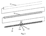
[0033] 図2は、図1の手術器具10の遠位端部の分解図を示す。図に示されるように、手術器具は、外側の細長形シャフト16、ローテータ18、及びマンドレル20を有する。組み立てられたとき、マンドレルはローテータ内に配置され、ローテータは外側の細長形シャフト内に配置される。示された実施形態で、ローテータは、回転可能な駆動チューブであり、マンドレルは、1つ又は複数の外科用留め具100を支持する螺刻部22を有する。図に示すように、外科用留め具は、螺刻マンドレル及びコイル本体104を受け入れる貫通穴を有するヘッド102が付いたコイル留め具であってもよい。さらに後述するように、トリガが作動するとローテータをマンドレルに対して回転するよう、トリガは動力伝達部(図示せず)を介してローテータに連結される。ローテータの回転は、マンドレルの螺刻部分に配置された外科用留め具を回転し、それが留め具を遠位方向に移動させ、最も遠位の留め具を補綴物及び/又は組織内へ配置する。このタイプの留め具配置システムのより詳細な記載が2013年11月8日出願の米国出願第14/075,398号(US2015/0133964号として公開)に提供され、これは全ての目的に関して本明細書に含まれる。
[0033] FIG. 2 illustrates an exploded view of the distal end of the
[0034] ここで図3を参照すると、手術器具10の1つの実施形態の内部の構成要素がより詳細に示される。図に示されるように、手術器具は、トリガ14と、トリガ及びハンドル12の両方に取り付けられたリターンバネ24と、を有する。リターンバネは、トリガが作動された構成のとき、トリガを最初の作動されない構成に戻すのを補助する復元力を提供する。トリガは、動力伝達部28の対応する歯車に係合するように構成された歯26を有する。示された実施形態で、動力伝達部は、トリガの移動をローテータ18の回転運動に変換して留め具を配置するよう調整された歯車列、並びにトリガの作動及びその後の解放の両方の間、ローテータを1方向に回転させるように制限するように調整された単一指向性歯車クラッチ30を有する。さらに詳細に後述するように、手術器具はさらに、操作者がローテータを選択的に回転させ、留め具の位置を調整するのを可能にする回転連結部32を有する。手術器具はまた、トリガが作動されるまでローテータ18の移動を制限する作動ロックアウトシステム40を有する。作動ロックアウトシステムのさらなる詳細は、図4〜図9を参照して後述する。
[0034] Referring now to FIG. 3, the internal components of one embodiment of the
[0035] 複数の歯車を含む動力伝達部を示し及び前述したが、トリガに加えられる力をローテータ又は他の留め具ドライバへ伝達するのに他の機構又は構成もまた使用してもよいことを理解するべきである。例えば、トリガの移動を留め具ドライバの関連する移動に伝達するのに、リンケージを使用してもよい。そのような構成は、直線的に移動される留め具ドライバを採用する実施形態に有益でありうる。代わりに、トリガを、ピン継手、ラック及びピニオンの構成、又はあらゆる他の適切な構造を介して留め具ドライバに直接連結してもよい。 [0035] Although a power transmission including a plurality of gears is shown and described above, other mechanisms or configurations may also be used to transfer the force applied to the trigger to the rotator or other fastener driver. You should understand. For example, linkage may be used to communicate the movement of the trigger to the associated movement of the fastener driver. Such a configuration may be beneficial to embodiments that employ a linearly moved fastener driver. Alternatively, the trigger may be directly coupled to the fastener driver via a pin joint, rack and pinion arrangement, or any other suitable structure.
[0036] いくつかの実施形態では、回転可能留め具ドライバの移動を1つの回転方向に限定し、留め具の配置の完了を確実にするように補助し、留め具が配置された後それの後退を防ぐことは有益でありうる。従って、動力伝達部は、1つの方向にのみ回転力を提供する1方向歯車クラッチ機構を有してもよい。示された実施形態で、歯車クラッチ機構30は、歯車クラッチが留め具の配置に対応する方向に回転させられるときに移動可能なアームに係合するショルダを有する。付勢構成要素が、アームをショルダと係合させるのを補助するようにアームに関連付けられる。クラッチ歯車が後方へ回転させられるとき、例えばトリガが第2(作動された)構成から第1(作動されない)構成へ戻って動くとき、アームがショルダと係合せず留め具ドライバを回転させるように、クラッチのカミング面がショルダの上方にアームをたわませる。いくつかの実施形態では、動力伝達部はさらに、歯車列が1つの方向に回転することのみを許可し、さらに留め具の望ましくない後退を防ぐのを支援するように構成されたラチェットを有する。
[0036] In some embodiments, the movement of the rotatable fastener driver is limited to one direction of rotation to assist in ensuring completion of fastener placement, and after the fastener has been deployed. Preventing setbacks can be beneficial. Therefore, the power transmission unit may have a one-way gear clutch mechanism that provides rotational force in only one direction. In the illustrated embodiment, the gear
[0037] 図4は、図3の作動ロックアウトシステム40の分解図である。明瞭にするため、ハンドル及び動力伝達部を含む手術器具の構成要素の多くは示さない。作動ロックアウトシステムは、制御タブ70及び複数のロッキングタブ42を含む。この実施形態では、制御タブは、後述するように移動可能なリンク内に一体的に形成される。さらにロッキングタブは、回転連結部32の第1半分34の外表面上に配置され、そこから外側に延在してその周囲に分散される。後述するように、回転連結部は、トリガをローテータ18に連結する。対応するロッキングタブ及び制御タブを図に示し前述したが、開示はそのように限定されないので、制御面及びロッキング面のあらゆる適切な組み合わせを代わりに使用してもよいことを理解すべきである。
[0037] FIG. 4 is an exploded view of the
[0038] 示された実施形態に説明されるように、制御タブ70の位置は、トリガ14に連結されたリンケージにより制御される。リンケージは第1リンク44を有し、その上に制御タブが配置される。第1リンクは、第1チャネル56及び第2チャネル60を有し、その中に第1ピン54及び軸58がそれぞれ受け入れられる。第1ピンは回転連結部の収容部38に取り付けられ、軸はハンドルに取り付けられる。この方法で、チャネル、第1ピン、及び軸は第1リンクの変換パスを形成し、それが次に第1リンク上に配置された制御タブ70の変換パスを形成する。示された実施形態では、第1及び第2チャネルは、第1リンク及び制御タブが、ローテータの軸方向に実質的に平行なパスに沿って近位及び遠位に往復運動するように調整される。しかしながら、本開示はそのように限定されないので、他の実施形態では、第1リンク及び制御タブをローテータを横断する方向に、又はあらゆる他の適切な方向に移動させるよう調整してもよいことを理解するべきである。
[0038] As described in the illustrated embodiment, the position of the
[0039] リンケージはまた、トリガを第1リンク44に連結する第2リンク46を有する。第2リンクは、第1リンクに連結された第2ピン50を介して第1リンクに連結される。第2ピンは、第2リンクの端部内に形成された細長形のスロット52内に受け入れられる。さらに、第2リンクの対向する端部は、第3ピン48及びねじりバネ66を含む付勢ピン継手を介してトリガに直接連結される。ねじりバネは、トリガの部分に連結された第1端部68a、及び第2リンク上に配置されたフック64により受け入れられる第2端部68bを有する。結果として、ねじりバネは第2リンクに回転付勢をもたらし、さらに詳細を後述するように、それがロック構成からロック解除構成への作動ロックアウトシステムの動きを促進する。ねじりバネが示されるが、本開示は特定のタイプの付勢構成要素に限定されないことを理解するべきである。他の実施形態では、圧縮バネ、弾性ロッド又はバンド、弾性アーム、又は第2リンクを適切な方向に付勢可能なあらゆる他の構造のような他の付勢構成要素を使用してもよい。
[0039] The linkage also has a
[0040] 作動ロックアウトシステム40の種々の構成要素を記載したが、その使用方法を図5〜図8を参照して詳細をさらに述べる。図5〜図6は、ロック構成、すなわち、トリガ14の作動前の作動ロックアウトシステム40を示す。ロック構成では、ねじりバネ66からの付勢力による第2リンク46の移動は制御ピン62により制限され、作動ロックアウトシステムがトリガの作動前にロック解除構成へ動くのを防ぐ。図6に示されるように、作動ロックアウトシステムがロック構成のとき、制御タブ70は、ロッキングタブ42の移動経路と整列し、ロッキングタブの移動を阻止する。従って、ロッキングタブと関連付けられたローテータもまた、移動を抑制される。
[0040] Having described the various components of the
[0041] 図7及び図8は、ロック解除構成の作動ロックアウトシステム40を示す。第1構成(例えば作動されない構成)から第2構成(例えば留め具が完全に配置された作動される構成)へのトリガ14の方向Aに沿った作動は、第2リンク46の方向Bへの関連する移動を起こし、ねじりバネ66は第3ピン48周辺で方向Cに回転付勢力をもたらし、作動ロックアウトシステムをロック解除構成へ促す。特に、回転力はスロット52に受け入れられた第2ピン50を介して第1リンク44へ伝達され、従って、第1リンクへ直線力をもたらし、それが次に第1リンクの方向Dの移動を起こす。図7に示されるように、第1リンクの変換は、ロッキングタブがその後の作動サイクルの部分の間、方向Eに自在に移動するように、制御タブ70をロッキングタブ42の移動経路との整列を外れて動かす。結果として、ローテータ18もまた、矢印Fで示されるように自在に回転する。
[0041] FIGS. 7 and 8 illustrate an
[0042] (回転連結部の第1半分34上に配置された)ロッキングタブ及び関連するローテータの回転は、動力伝達部(図示せず)により駆動される。トリガが第2位置から第1位置へ戻るとき、例えばリターンバネ24によりもたらされた付勢力により、第1及び第2リンクの運動は逆転され、作動ロックアウトシステムをロック構成に動かして戻す。従って、ローテータの回転を最初制限しその後許可するプロセスは、手術器具のそれぞれの作動の間に起こる。
[0042] The rotation of the locking tab (disposed on the
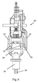
[0043] 製造中、手術器具内に位置する外科用留め具のスタックの適切な位置決めを確実にするため、器具の完全な分解を必要とすることなく回転可能な留め具ドライバの回転を可能にするのが望ましいかもしれない。従って、及び前述のように、いくつかの実施形態では、手術器具は、マンドレル20に沿って留め具100の位置を調整するよう、ローテータ18、又は他の適切な留め具ドライバの回転を選択的に可能にする回転連結部を有する。例えば図9は、動力伝達部からの回転力が回転連結部を通してローテータへ伝達されるよう連結された構成の回転連結部32の1つの実施形態を示す。示された実施形態で、回転連結部は、動力伝達部に連結された第1半分34、及びローテータに連結された第2半分36を有する。連結部の第1半分は、キー嵌合部(図示せず)を介して動力伝達部のシャフト歯車28aに連結される。連結部をシャフト歯車の近位及び遠位の両方に摺動しうるように、キー嵌合部は、連結部の第1半分とシャフト歯車の間の摺動可能な連結を形成する。連結部の第1及び第2半分は、インタフェース74において相互に作用する。示された実施形態で、インタフェースは連動刻み目構造のような連動機能を有する。しかしインタフェースは、締まり嵌め、ナット及びボルト接続具、又は連結部の第1半分と第2半分の間で回転力を伝達可能で、関連するトリガから留め具ドライバを連結及び分断するよう選択的に係合及び係脱しうるあらゆる他の適切な構造を含むが、それらに限定されないあらゆる数のインタフェースに対応してもよいことを理解するべきである。示された実施形態で、予め圧縮されたバネ74は、ローラベアリング76と連結部34の第1半分の対向する面との間に位置する。よって連結部の第1半分は、遠位方向に連結部の第2半分へ向かって付勢され、これは、係合された構成に対応する。図10に示されるように、ローテータを回転させるためにトリガからローテータを分断するのが望ましいとき、ユーザは連結部の第1半分を近位方向Gに移動させ、インタフェース72を係合から外して移動させる。ローテータはそれからトリガから分断され、必要に応じて方向Hに自在に回転させ、留め具のスタックの位置を調整してもよい。適切に位置決められると、連結部の第1半分は解放される。解放された後、それから連結部の第1半分は付勢バネにより遠位に移動され、連結部の半分の間のインタフェースを再係合し、ローテータをトリガと再連結する。
[0043] To ensure proper positioning of a stack of surgical fasteners located within a surgical instrument during manufacture, allowing rotation of a rotatable fastener driver without requiring complete disassembly of the instrument It may be desirable to do so. Thus, and as noted above, in some embodiments, the surgical instrument selectively rotates the
[0044] 本教示を種々の実施形態及び例と関連して記載したが、本教示がそのような実施形態又は例に限定されることを意図しない。反対に本教示は、当業者が理解するように、種々の代替、改良及び均等物を含む。従って、前述の記載及び図は例示のみを目的とするものである。 [0044] While the present teachings have been described in connection with various embodiments and examples, the present teachings are not intended to be limited to such embodiments or examples. On the contrary, the present teachings include various alternatives, modifications, and equivalents, as will be appreciated by those skilled in the art. Accordingly, the foregoing description and drawings are for purposes of illustration only.
Claims (11)
前記動力伝達部に作動可能に関連し、ロック構成とロック解除構成との間を移動可能である作動ロックアウトシステムであって、前記作動ロックアウトシステムが前記ロック構成にあるとき、前記留め具ドライバが前記第1位置から前記第2位置へ移動するのを防ぎ、前記トリガの前記第1構成から前記第2構成への作動が、前記作動ロックアウトシステムを前記ロック構成から前記ロック解除構成に動かす、作動ロックアウトシステムと、を備える手術器具。 A power transmission having a trigger and a fastener driver operably coupled to the trigger, wherein actuation of the trigger from a first configuration to a second configuration causes the fastener driver to be in at least a first position. and moving between the second position, the first position of the fastener driver is a first rotational position of the longitudinal axis of the fastener driver, the second position of the fastener driver said fastener driver A power transmission unit that is a second rotational position around the longitudinal axis of
Operably associated with said power transmission unit, an actuating lockout system is movable between a locked configuration and an unlocked configuration, when the operating lock-out system is in the locked configuration, said fastener driver There prevented from the first position to move to the second position, operation of the second configuration from the first configuration of the trigger moves the actuating lockout system to the unlocked configuration of the locking arrangement And a surgical lockout system.
前記留め具ドライバに関連する1つ又は複数のロッキング面と、
制御面であって、前記作動ロックアウトシステムが前記ロック構成にあるとき、前記1つ又は複数のロッキング面の移動経路に整列させられ、前記作動ロックアウトシステムを前記ロック構成から前記ロック解除構成に動かすことが、前記制御面を前記1つ又は複数のロッキング面の移動経路から外して動かす、制御面と、を備える、請求項1に記載の手術器具。 The actuation lockout system is
One or more locking surfaces associated with the fastener driver;
A control surface that is aligned with the path of travel of the one or more locking surfaces when the actuation lockout system is in the locking configuration to move the actuation lockout system from the locking configuration to the unlocking configuration. The surgical instrument of claim 1, wherein moving comprises moving the control surface out of a path of travel of the one or more locking surfaces.
前記留め具ドライバに関連する1つ又は複数のロッキング面と、
制御面であって、前記作動ロックアウトシステムが前記ロック構成にあるとき、前記1つ又は複数のロッキング面の移動経路に整列させられ、前記作動ロックアウトシステムを前記ロック構成から前記ロック解除構成に動かすことが、前記ロッキング面を前記制御面との整列から外して動かす、制御面と、を備える、請求項1に記載の手術器具。 The actuation lockout system is
One or more locking surfaces associated with the fastener driver;
A control surface that is aligned with the path of travel of the one or more locking surfaces when the actuation lockout system is in the locking configuration to move the actuation lockout system from the locking configuration to the unlocking configuration. The surgical instrument of claim 1, wherein moving comprises moving the locking surface out of alignment with the control surface.
前記留め具ドライバに関連する1つ又は複数のロッキング面と、
前記トリガが前記第1構成から前記第2構成へ作動させられるとき、ロック構成とロック解除構成との間を動かされ、前記ロック構成のとき、前記1つ又は複数のロッキング面のうち少なくとも1つの運動を阻止し、前記第1位置と前記第2位置との間の前記留め具ドライバの移動を妨げる制御面と、を備える手術器具。 A trigger and a fastener driver operably coupled to the trigger, wherein actuation of the trigger from a first configuration to a second configuration causes the fastener driver to move between at least a first position and a second position. move to the first position of the fastener driver is first rotational position of the longitudinal axis of the fastener driver, a second position of the fastener driver of the longitudinal axis of the fastener driver A power transmission part , which is a two-rotation position ,
One or more locking surfaces associated with the fastener driver;
When the trigger is actuated from the first configuration to the second configuration, it is moved between a locking configuration and an unlocking configuration, and in the locking configuration at least one of the one or more locking surfaces. A control surface that blocks movement and prevents movement of the fastener driver between the first position and the second position.
Priority Applications (1)
| Application Number | Priority Date | Filing Date | Title |
|---|---|---|---|
| JP2020137081A JP6963661B2 (en) | 2015-06-30 | 2020-08-14 | Operational lockout of surgical instruments |
Applications Claiming Priority (3)
| Application Number | Priority Date | Filing Date | Title |
|---|---|---|---|
| US14/755,347 | 2015-06-30 | ||
| US14/755,347 US10405858B2 (en) | 2015-06-30 | 2015-06-30 | Actuation lockout for a surgical instrument |
| PCT/US2016/040018 WO2017004155A1 (en) | 2015-06-30 | 2016-06-29 | Actuation lockout for a surgical instrument |
Related Child Applications (1)
| Application Number | Title | Priority Date | Filing Date |
|---|---|---|---|
| JP2020137081A Division JP6963661B2 (en) | 2015-06-30 | 2020-08-14 | Operational lockout of surgical instruments |
Publications (3)
| Publication Number | Publication Date |
|---|---|
| JP2018519900A JP2018519900A (en) | 2018-07-26 |
| JP2018519900A5 JP2018519900A5 (en) | 2019-06-13 |
| JP6751416B2 true JP6751416B2 (en) | 2020-09-02 |
Family
ID=56409711
Family Applications (2)
| Application Number | Title | Priority Date | Filing Date |
|---|---|---|---|
| JP2017564682A Active JP6751416B2 (en) | 2015-06-30 | 2016-06-29 | Actuator lockout for surgical instruments |
| JP2020137081A Active JP6963661B2 (en) | 2015-06-30 | 2020-08-14 | Operational lockout of surgical instruments |
Family Applications After (1)
| Application Number | Title | Priority Date | Filing Date |
|---|---|---|---|
| JP2020137081A Active JP6963661B2 (en) | 2015-06-30 | 2020-08-14 | Operational lockout of surgical instruments |
Country Status (6)
| Country | Link |
|---|---|
| US (4) | US10405858B2 (en) |
| EP (2) | EP3316796B1 (en) |
| JP (2) | JP6751416B2 (en) |
| CN (2) | CN107809970B (en) |
| ES (1) | ES2895727T3 (en) |
| WO (1) | WO2017004155A1 (en) |
Families Citing this family (5)
| Publication number | Priority date | Publication date | Assignee | Title |
|---|---|---|---|---|
| US10405858B2 (en) | 2015-06-30 | 2019-09-10 | C.R. Bard, Inc. | Actuation lockout for a surgical instrument |
| KR102118720B1 (en) * | 2018-12-31 | 2020-06-04 | 주식회사 리브스메드 | Locking Apparatus |
| KR102118721B1 (en) | 2018-12-31 | 2020-06-04 | 주식회사 리브스메드 | Surgical instrument |
| WO2020214657A1 (en) * | 2019-04-17 | 2020-10-22 | Davol Inc. | Surgical instrument with fastener preload lock-out |
| CN111035418B (en) * | 2019-12-31 | 2021-04-16 | 重庆西山科技股份有限公司 | Visual direction-changing operation power device |
Family Cites Families (41)
| Publication number | Priority date | Publication date | Assignee | Title |
|---|---|---|---|---|
| US5258010A (en) * | 1991-05-30 | 1993-11-02 | United States Surgical Corporation | Anvilless surgical apparatus for applying surgical fasteners |
| US5827263A (en) | 1994-07-21 | 1998-10-27 | Genzyme Corporation | Surgical instrument handle |
| US5997552A (en) * | 1995-10-20 | 1999-12-07 | United States Surgical Corporation | Meniscal fastener applying device |
| US5665105A (en) | 1996-03-20 | 1997-09-09 | Snowden Pencer/Genzyme Corporation | Radially adjustable surgical instrument for heart surgery |
| AU4494997A (en) * | 1996-09-20 | 1998-04-14 | United States Surgical Corporation | Coil fastener applier and remover |
| US6010513A (en) * | 1997-11-26 | 2000-01-04 | Bionx Implants Oy | Device for installing a tissue fastener |
| US6457625B1 (en) | 1998-02-17 | 2002-10-01 | Bionx Implants, Oy | Device for installing a tissue fastener |
| US6042601A (en) | 1998-03-18 | 2000-03-28 | United States Surgical Corporation | Apparatus for vascular hole closure |
| US7485124B2 (en) * | 2000-10-19 | 2009-02-03 | Ethicon Endo-Surgery, Inc. | Surgical instrument having a fastener delivery mechanism |
| US6425900B1 (en) | 2000-10-19 | 2002-07-30 | Ethicon Endo-Surgery | Method for attaching hernia mesh |
| US8231639B2 (en) * | 2001-11-28 | 2012-07-31 | Aptus Endosystems, Inc. | Systems and methods for attaching a prosthesis within a body lumen or hollow organ |
| US8926637B2 (en) * | 2003-06-13 | 2015-01-06 | Covidien Lp | Multiple member interconnect for surgical instrument and absorbable screw fastener |
| US7083075B2 (en) * | 2003-09-29 | 2006-08-01 | Ethicon Endo-Surgery, Inc. | Multi-stroke mechanism with automatic end of stroke retraction |
| US7771440B2 (en) | 2005-08-18 | 2010-08-10 | Ethicon Endo-Surgery, Inc. | Method and apparatus for endoscopically performing gastric reduction surgery in a single pass |
| US7886953B2 (en) | 2005-08-18 | 2011-02-15 | Ethicon Endo-Surgery, Inc. | Fired device lockout for a curved cutter stapler with a free moving trigger |
| US7540400B2 (en) | 2006-01-06 | 2009-06-02 | Staples The Office Superstore, Llc | Stapler having a moveable strike plate with lockout mechanism |
| US8794496B2 (en) | 2006-09-11 | 2014-08-05 | Covidien Lp | Rotating knob locking mechanism for surgical stapling device |
| US7963431B2 (en) * | 2006-10-06 | 2011-06-21 | Tyco Healthcare Group, Lp | Grasping jaw mechanism |
| US7967178B2 (en) | 2006-10-06 | 2011-06-28 | Tyco Healthcare Group Lp | Grasping jaw mechanism |
| US7569063B2 (en) | 2006-10-13 | 2009-08-04 | Sofradim Production Sas | Instrument for storing and dispensing a surgical fastener |
| US7931660B2 (en) | 2007-05-10 | 2011-04-26 | Tyco Healthcare Group Lp | Powered tacker instrument |
| US8408439B2 (en) * | 2007-06-22 | 2013-04-02 | Ethicon Endo-Surgery, Inc. | Surgical stapling instrument with an articulatable end effector |
| FR2924917B1 (en) | 2007-12-13 | 2011-02-11 | Microval | APPARATUS FOR INSTALLING SUTURE SPIERS RESULTING FROM A SHAPE MEMORY METAL WIRE. |
| US7905381B2 (en) | 2008-09-19 | 2011-03-15 | Ethicon Endo-Surgery, Inc. | Surgical stapling instrument with cutting member arrangement |
| US7866527B2 (en) * | 2008-02-14 | 2011-01-11 | Ethicon Endo-Surgery, Inc. | Surgical stapling apparatus with interlockable firing system |
| US8439898B2 (en) | 2008-06-17 | 2013-05-14 | Usgi Medical, Inc. | Endoscopic tissue anchor deployment |
| US8083120B2 (en) * | 2008-09-18 | 2011-12-27 | Ethicon Endo-Surgery, Inc. | End effector for use with a surgical cutting and stapling instrument |
| US9517027B2 (en) | 2009-07-10 | 2016-12-13 | Facet Techonologies, Llc | Advancement mechanism for cartridge-based devices |
| US8683895B2 (en) | 2010-02-23 | 2014-04-01 | Kensey Nash Corporation | Single revolution snap action drive for surgical fasteners |
| AU2015200218B2 (en) * | 2010-10-11 | 2017-06-01 | Cook Medical Technologies Llc | Medical devices with detachable pivotable jaws |
| CA2833572A1 (en) | 2011-05-03 | 2012-11-08 | Biodynamics, Llc | Bone tack driver |
| US9078648B2 (en) | 2011-11-07 | 2015-07-14 | C.R. Bard, Inc. | Instruments for delivering transfascial sutures and methods of transfascial suturing |
| EP2785397B1 (en) | 2011-12-02 | 2020-12-30 | Bioceptive, Inc. | Apparatus for inserting a device or pharmaceutical into a uterus |
| US9089379B2 (en) | 2012-07-18 | 2015-07-28 | Jmea Corporation | Multi-impact system for prosthesis deployment device |
| US9364235B2 (en) | 2013-03-14 | 2016-06-14 | C.R. Bard, Inc. | Power assist device for a surgical instrument |
| US9649109B2 (en) | 2013-03-14 | 2017-05-16 | C.R. Bard, Inc. | Surgical instrument with an actuation lockout |
| US9526498B2 (en) | 2013-09-17 | 2016-12-27 | Covidien Lp | Surgical device with a trigger lockout mechanism device |
| US9675353B2 (en) | 2013-11-08 | 2017-06-13 | C.R. Bard, Inc. | Surgical fasteners and associated deployment devices |
| CN106470630B (en) | 2014-07-04 | 2019-10-11 | 柯惠有限合伙公司 | Surgical fastener bringing device and method for endoscopic procedure |
| US10368876B2 (en) * | 2015-01-15 | 2019-08-06 | Covidien Lp | Endoscopic reposable surgical clip applier |
| US10405858B2 (en) | 2015-06-30 | 2019-09-10 | C.R. Bard, Inc. | Actuation lockout for a surgical instrument |
-
2015
- 2015-06-30 US US14/755,347 patent/US10405858B2/en active Active
-
2016
- 2016-06-29 ES ES16738614T patent/ES2895727T3/en active Active
- 2016-06-29 JP JP2017564682A patent/JP6751416B2/en active Active
- 2016-06-29 EP EP16738614.3A patent/EP3316796B1/en active Active
- 2016-06-29 EP EP21183972.5A patent/EP3909519A1/en active Pending
- 2016-06-29 CN CN201680038071.8A patent/CN107809970B/en active Active
- 2016-06-29 WO PCT/US2016/040018 patent/WO2017004155A1/en active Application Filing
- 2016-06-29 CN CN202011085415.5A patent/CN112451018A/en active Pending
-
2019
- 2019-07-23 US US16/519,540 patent/US11147550B2/en active Active
-
2020
- 2020-08-14 JP JP2020137081A patent/JP6963661B2/en active Active
-
2021
- 2021-10-15 US US17/502,850 patent/US11751868B2/en active Active
-
2023
- 2023-08-04 US US18/365,610 patent/US20230371946A1/en active Pending
Also Published As
| Publication number | Publication date |
|---|---|
| CN112451018A (en) | 2021-03-09 |
| US10405858B2 (en) | 2019-09-10 |
| EP3316796A1 (en) | 2018-05-09 |
| US20220031308A1 (en) | 2022-02-03 |
| EP3316796B1 (en) | 2021-08-25 |
| CN107809970B (en) | 2020-11-03 |
| US11751868B2 (en) | 2023-09-12 |
| JP6963661B2 (en) | 2021-11-10 |
| JP2020203097A (en) | 2020-12-24 |
| JP2018519900A (en) | 2018-07-26 |
| US11147550B2 (en) | 2021-10-19 |
| CN107809970A (en) | 2018-03-16 |
| ES2895727T3 (en) | 2022-02-22 |
| WO2017004155A1 (en) | 2017-01-05 |
| US20190343516A1 (en) | 2019-11-14 |
| US20230371946A1 (en) | 2023-11-23 |
| US20170000481A1 (en) | 2017-01-05 |
| EP3909519A1 (en) | 2021-11-17 |
Similar Documents
| Publication | Publication Date | Title |
|---|---|---|
| JP6963661B2 (en) | Operational lockout of surgical instruments | |
| US11896338B2 (en) | Manual release for medical device drive system | |
| JP7179827B2 (en) | Surgical system with articulation bailout | |
| RU2628048C2 (en) | Surgical instrument with various speed direction switching mechanism | |
| CN106572853B (en) | Closed-lock system for surgical instruments | |
| AU2020239733B2 (en) | Actuation lockout for a surgical instrument | |
| AU2019206351B2 (en) | Articulating surgical instruments | |
| US11944289B2 (en) | Articulating surgical instruments | |
| EP4129215A1 (en) | Articulating surgical instruments |
Legal Events
| Date | Code | Title | Description |
|---|---|---|---|
| A521 | Request for written amendment filed |
Free format text: JAPANESE INTERMEDIATE CODE: A523 Effective date: 20190510 |
|
| A621 | Written request for application examination |
Free format text: JAPANESE INTERMEDIATE CODE: A621 Effective date: 20190510 |
|
| A977 | Report on retrieval |
Free format text: JAPANESE INTERMEDIATE CODE: A971007 Effective date: 20200323 |
|
| A131 | Notification of reasons for refusal |
Free format text: JAPANESE INTERMEDIATE CODE: A131 Effective date: 20200409 |
|
| A521 | Request for written amendment filed |
Free format text: JAPANESE INTERMEDIATE CODE: A523 Effective date: 20200706 |
|
| TRDD | Decision of grant or rejection written | ||
| A01 | Written decision to grant a patent or to grant a registration (utility model) |
Free format text: JAPANESE INTERMEDIATE CODE: A01 Effective date: 20200720 |
|
| A61 | First payment of annual fees (during grant procedure) |
Free format text: JAPANESE INTERMEDIATE CODE: A61 Effective date: 20200814 |
|
| R150 | Certificate of patent or registration of utility model |
Ref document number: 6751416 Country of ref document: JP Free format text: JAPANESE INTERMEDIATE CODE: R150 |
|
| R250 | Receipt of annual fees |
Free format text: JAPANESE INTERMEDIATE CODE: R250 |